Babylog 8000 plus. Infant Care Ventilator. Operating Instructions Software 5.n MT
|
|
|
- Garry Gibbs
- 5 years ago
- Views:
Transcription

1 DM E D I C A L Babylog 8000 plus Infant Care Ventilator Operating Instructions Software 5.n MT
2 NOTICE Proprietary Information This document contains information in which Draeger Medical, Inc. claimed proprietary rights. The information may not be reproduced in whole or in part except as authorized in writing by Dräger. This information is the property of Draeger Medical, Inc., it is provided solely for the use intended. Repairs/Modifications Repairs on this device shall be performed only by DrägerService or Factory Authorized Service Centers. Information about repairs can be obtained from Dräger or Authorized Dealers. Draeger Medical, Inc. will not be responsible for injury to persons or damage to property arising directly or indirectly out of unauthorized repairs or modifications to this device. Furthermore, any unauthorized repairs or modifications void any warranty extended by Dräger. This document is provided for your information only. It will not be exchanged or updated without request. Trademarks The Dräger name and logo are registered trademarks of Dräger. Babylog is a registered trademark of Dräger. ThinkJet is a registered trademark of Hewlett Packard Corporation Dräger Medical AG & Co. KGaA, All rights reserved, subject to modifications
3 MT
4 Working with these Operating Instructions Working with these Operating Instructions Header line the title... of the main chapter The title of the respective sub-section is printed underneath the main header to help you find your way quickly from subject to subject. Page body... the Operating Instructions combine text and illustrations. The information is presented in the form of required steps of action, giving the user hands-on experience in learning how to use the ventilator. Calibrating the O2-Sensor Manually After sensor has been replaced, but possible at all times. 1 Press»Cal Config.«menu key. 1 D Babylog 8000 plus Preparation Calibrations Left-hand column... the text provides explanations and instructs users step-by-step in the practical use of the product, with short, clear instructions in easy to follow sequences. Bullet points indicate separate actions. Where several actions are described, numbers are used to refer both to relevant details in the illustrations and to specify the sequence of actions. 2 Press»O2-Cal«menu key. 3 After about 5 minutes, O2-Cal disappears from the display, calibration is now completed. 2 3 The respective text message may now be cleared: 1 Press»Confirm«key. Right-hand column... the illustrations provide the visual reference for the text and make it easier to locate the various parts of the device. Elements mentioned in the text are highlighted. Unnecessary details are omitted. Rendering of screen displays guide the user and allow to reconfirm actions performed. 1 D Babylog 8000 plus Typing conventions... Controls are designated as»control Name«, e.g:»peep/cpap«screen messages are printed in bold, e.g: Calibrate flow sensor! Strictly follow this Operator's Instruction Manual Any use of the product requires full understanding and strict observation of all portions of these instructions. The equipment is only to be used for the purpose specified under "Intended Use" (see page 18) and in conjunction with appropriate airway monitoring (see page 19). Observe all WARNINGS and CAUTIONS as rendered throughout this manual and on labels on the equipment. 4
5 Contents Contents Important Safety Information READ THIS FIRST! 7 Intended Use 17 Operating Concept 21 Preparation 27 Operation 51 Care 97 Troubleshooting 105 What's What 111 Technical Data 119 Theory of Operation 129 Ordering Information 143 Index 144 5
6 This page intentionally left blank 6
7 Important Safety Information Contents Important Safety Information Contents Operator's Responsibility for Patient Safety... 8 Limitation of Liability... 8 Warranty... 9 Definitions Summary of WARNINGS and CAUTIONS General Precautions...10 Precautions During Preparation Precautions During Operation...13 Precautions During Care Precautions During Maintenance
8 Important Safety Information Operator's Responsibility for Patient Safety Limitation of Liability Operator's Responsibility for Patient Safety Limitation of Liability Strictly follow this Operator's Instruction Manual. Any use of the product requires full understanding and strict observation of all portions of these instructions. The equipment is only to be used for the purpose specified under "Intended Use" (page 18) and in conjunction with appropriate airway monitoring (see page 19). Observe all WARNINGS and CAUTIONS as rendered throughout this manual and on labels on the equipment. The design of the equipment, the accompanying literature, and the labeling on the equipment take into consideration that the purchase and use of the equipment are restricted to trained professionals, and that certain inherent characteristics of the equipment are known to the trained operator. Instructions, warnings, and caution statements are limited, therefore, largely to the specifics of the Dräger design. This publication excludes references to various hazards which are obvious to a medical professional and operator of this equipment, to the consequences of product misuse, and to potentially adverse effects in patients with abnormal conditions. Product modification or misuse can be dangerous. Dräger disclaims all liability for the consequences of product alterations or modifications, as well as for the consequences which might result from the combination of this product with other products whether supplied by Dräger or by other manufacturers if such a combination is not endorsed by Dräger. Dräger's liability, whether arising out of or related to manufacture and sale of the goods, their installation, demonstration, sales representation, use, performance, or otherwise, including any liability based upon Dräger's Product Warranty, is subject to and limited to the exclusive terms and conditions as set forth, whether based upon breach of warranty or any other cause of action whatsoever, regardless of any fault attributable to Dräger and regardless of the form of action (including, without limitation, breach of warranty, negligence, strict liability, or otherwise). THE STATED EXPRESSED WARRANTlES ARE IN LlEU OF ALL OTHER WARRANTIES, EXPRESSED OR IMPLIED, INCLUDING, WITHOUT LIMITATION, WARRANTlES OF MERCHANTABILITY, FITNESS FOR ANY PARTICULAR PURPOSE, OR NONINFRINGEMENT. Dräger shall not be liable for, nor shall buyer be entitled to recover any special incidental, or consequential damages or for any liability incurred by buyer to any third party in any way arising out of or relating to the goods. The operators of the ventilator system must recognize their responsibility for choosing appropriate safety monitoring that supplies adequate information on equipment performance and patient condition. Patient safety may be achieved through a wide variety of different means ranging from electronic surveillance of equipment performance and patient condition to simple, direct observation of clinical signs. The responsibility for the selection of the best level of patient monitoring lies solely with the equipment operator (see also page 19, "Mandatory Ventilation Monitoring"). 8
9 Important Safety Information Warranty Warranty All Dräger products are guaranteed to be free of defects for a period of one year from date of delivery. The following are exceptions to this warranty: 1. The defect shall be a result of workmanship or material. Defects caused by misuse, mishandling, tampering, or by modifications not authorized by Dräger or its representatives are not covered. 2. Rubber and plastic components and materials are warranted to be free of defects at time of delivery. 3. Oxygen sensors capsules have a six-month limited warranty from the date of delivery. Any product which proves to be defective in workmanship or material will be replaced, credited, or repaired with Dräger holding the option. Dräger is not respon-sible for deterioration, wear, or abuse. In any case, Dräger will not be liable beyond the original selling price. Application of this warranty is subject to the following conditions: 1. Dräger or its authorized representative must be promptly notified, in writing, upon detection of the defective material or equipment. 2. Defective material or equipment must be returned, shipping prepaid, to Dräger or its authorized representative. 3. Examination by Dräger or its authorized representative must confirm that the defect is covered by the terms of this warranty. 4. Notification in writing, of defective material or equipment must be received by Dräger or its authorized representative no later than two (2) weeks following expiration of this warranty. The above is the sole warranty provided by Dräger. No other warranty expressed or implied is intended. Representatives of Dräger are not authorized to modify the terms of this warranty. Draeger Medical, Inc., Telford, PA 9
10 Important Safety Information Definitions Summary of WARNINGS and CAUTIONS Definitions A WARNING statement refers to conditions with a possibility of personal injury if disregarded. CAUTION! A CAUTION statement designates the possibility of damage to equipment if disregarded. Summary of WARNINGS and CAUTIONS General Precautions Strictly follow this Operator's Instruction Manual Any use of the product requires full understanding and strict observation of all portions of these instructions. The equipment is only to be used for the purpose specified under "Intended Use" (page 18) and in conjunction with appropriate airway monitoring (see page 19). Observe all WARNINGS and CAUTIONS as rendered throughout this manual and on labels on the equipment. NOTE: A NOTE provides additional information intended to avoid inconveniences during operation. Inspection = examination of actual condition Service = measures to maintain specified condition Repair = measures to restore specified condition Maintenance = inspection, service, and repair, where necessary Preventive = Maintenance measures at regular Maintenance intervals Typing conventions in this manual Controls (knobs, hard keys and menu keys) are designated as»control Name«, e.g.:»peep/cpap«on-screen messages are printed in bold, e.g.: Calibrate flow sensor! Babylog 8000 plus is solely intended for use by physicians or by allied health care professionals on the order of a physician. All users must be properly trained and completely familiar with these Operating Instructions. This device is to be used only in rooms with line power installations complying with national safety standards for hospital patient rooms. (e.g., IEC 601.1, "Safety of Medical Equipment). To maintain grounding integrity, connect only to a"hospital grade" receptacle. Always disconnect supply before servicing. DANGER, risk of explosion if used in the presence of flammable anesthetics. This device is neither approved nor certified for use in areas where combustible or explosive gas mixtures with air or with nitrous oxide are likely. 10
11 Important Safety Information Summary of WARNINGS and CAUTIONS Mobile telephones must not be used within 10 meters (33 feet) of the equipment. Mobile telephones can interfere with the function of electromedical equipment and therefore endanger the patient! Do not use ventilator in conjunction with nuclear spin tomography (MRT, NMR, or NMI)! Equipment malfunction may result. Sidestream monitors may cause negative pressures in the event of a blocked inspiratory circuit. Always connect monitoring lines of a suctioning sidestream monitor via adapter with safety valve. If a fault is detected in the ventilator and its life-support functions are in doubt, ventilation must be started without delay with an independent ventilation device (resuscitation bag) - using PEEP and/or increased inspiratory O2 concentration where necessary and appropriate. The unit should then be removed from use and serviced by an authorized service technician. CAUTION! Restriction of Distribution Federal Law and Regulations in the United States and Canada restrict this device to sale by or on the order of a physician. Whenever a patient is connected to the ventilator, constant attention by qualified medical staff is required in order to provide immediate corrective action in case of a malfunction. Always use independent apnea monitor when the built-in apnea monitoring has been switched off. The operator of the ventilator must still assume full responsibility for proper ventilation and patient safety in all situations. In case of malfunction of any of the built-in monitoring a substitute must be provided in order to maintain an adequate level of monitoring. The operator of the ventilator must still assume full responsibility for proper ventilation and patient safety in all situations. 11
12 Important Safety Information Summary of WARNINGS and CAUTIONS Precautions During Preparation Always install expiratory valve that has been cleaned and disinfected. Treatment of batteries and O2-sensor capsules: Do not throw into fire! Risk of explosion. Do not force open! Danger of bodily injury. Follow all local, state, and federal regulations with respect to environmental protection when disposing of batteries and O2-sensor capsules. Always use medical grade oxygen and air that is dry and free from dust and oil. Contaminated gas may cause ventilator malfunction. Always provide adequate ventilation! When the equipment is being operated with O2, ensure that the ambient concentration does not exceed 24% O2. Otherwise, the risk of fire may be increased. To maintain grounding integrity, connect only to a "hospital grade" receptacle. Always disconnect supply before servicing. Dräger cannot warrant or endorse the safe performance of third party humidifiers for use with the Babylog 8000 plus infant ventilator. Specifically, combinations of humidifiers not intended for use with infant patients bear risks of delivering breathing gas not maintained at a proper temperature. Excessive rainout in the inspiratory line of the breathing circuit may disable the flow and volume measuring capabilities of the Babylog 8000 plus ventilator. Increased pneumatic resistance and compliance in the inspiratory line caused by a humidifier may result in inaccurate airway pressure readings. We recommend contacting the manufacturers /distributors of heated humidifying devices about compliance of their products with the requested performance characteristics. Dräger cannot warrant or endorse the safe performance of third party ventilator circuits for use with the Babylog 8000 plus infant ventilator. Increased pneumatic resistance caused by some circuit systems may result in inaccurate airway pressure readings. Only use circuits with an inner diameter of at least 10 mm (0.4 inch) We recommend contacting the manufacturers /distributors of infant patient circuits regarding compliance of their products with the requested performance characteristics (see p. 32). In order to avoid any risk of electric shock in the event of faulty grounding of patient monitoring equipment, do not use antistatic or electrically conductive patient circuits Note arrows for inspiratory and expiratory connector on ventilator ports. If circuit ends are confused, humidification will not be effective. 12
13 Important Safety Information Summary of WARNINGS and CAUTIONS Precautions During Operation To maintain grounding integrity, connect only to a "hospital grade" receptacle. Always disconnect supply before servicing. Always use ventilator that has been cleaned and disinfected and has been successfully tested to be ready for operation. Always use safety valve when connecting sampling CO2 or NO monitors. Otherwise negative airway pressures may result in the event of a blocked inspiratory circuit. The ventilator is ready for operation only when: - it is completely assembled with all required auxiliary equipment in place, - all sensors are calibrated (O2, Flow), - all checks have been completed successfully. CAUTION! Do not place containers of liquids on top of the Babylog 8000 plus ventilator. Liquids penetrating the ventilator can cause equipment malfunction and damage. CAUTION! If Air and O2 supply lines are contaminated with particles or moisture, as is likely during the use with a medical air compressor, use high pressure line filters that retain at least 0.1 micron particles and stop water droplets (e.g. Dräger part no. D , D ). CAUTION! Always hold end cuffs when pulling a circuit from a port. Otherwise damage to the patient circuit will result. Whenever a patient is connected to the ventilator, constant attention by qualified medical staff is required in order to provide immediate corrective action in case of a malfunction. Not any and every critical condition can be expected to cause a ventilator alarm. If a fault is detected in the ventilator and its life support functions are in doubt, ventilation must be started without delay with an independent ventilation device (resuscitation bag) - using PEEP and/or increased inspiratory O2 concentration where necessary and appropriate. The unit should then be removed from use and serviced by an authorized service technician. In case of malfunction of any of the built-in monitoring, a substitute must be provided in order to maintain an adequate level of monitoring. The operator of the ventilator must still assume full responsibility for proper ventilation and patient safety in all situations. This is particularly important when, during a nebulizer treatment, the Babylog flow sensor has been removed to protect it against contamination. The operator of the ventilator must still assume full responsibility for proper ventilation and patient safety when switching off flow measurement during nasal CPAP. Use appropriate external monitoring to assure patient's oxygenation status and to detect apnea. 13
14 Important Safety Information Summary of WARNINGS and CAUTIONS Always heed all precautions and follow all hospital protocols with respect to the administration of oxygen. It is absolutely essential that the ventilation regime and the oxygen concentration administered is selected on the basis of arterially measured oxygen partial pressure in the blood of the infant. This is the only way of minimizing the risk of both hyperoxemia, which might cause, above all, retrolental fibroplasia, and hypoxemia, which might contribute to intraventricular hemorrhage and damage to the baby's brain. The accuracy of the concentration of oxygen delivered to the patient must be monitored at all times. If the oxygen analyzer integrated into the Babylog 8000 plus ventilator is not operable, an independent oxygen monitor must be connected to the inspiratory limb of the patient circuit. Always use extreme caution when using oxygen! Oxygen intensely supports any burning! No smoking, no open fire in areas where oxygen is in use! Always provide adequate ventilation in order to maintain ambient O2 concentrations < 24 %. Always secure O2 cylinders against tipping, do not expose to extreme heat. Do not use oil or grease on O2 equipment such as tank valves or pressure regulators. Do not touch with oily hands. Risk of fire! Open and close valves slowly, with smooth turns. Do not use any tools. Do not block air intake. Ventilator malfunction will result. Be careful not to cause back pressure when using scavenging systems. Aerosol medications may clog expiratory valves which can impair ventilation. Therefore, exchange expiratory valve immediately after nebulizing aerosols. Aerosol medications may clog bacteria filters which can impair ventilation. Therefore, do not use bacteria filters at the nebulizer output or in the expiratory side of the patient circuit. The wires of the Babylog 8000 plus flow sensor operate at a high temperature. If the sensor is left in the patient circuit for an extended period of time while nebulizing without cleaning, residue buildup might result from the pharmaceutical aerosols that would impair flow measurement. As a worst case, these residues might ignite! To prevent this, it is not sufficient to remove the electrical connector from the flow sensor. Therefore, it is mandatory to physically remove the flow sensor from the circuit, (resp. the flow sensor element from the wye) before beginning any nebulizer treatment. When the flow and volume measuring system of the Babylog 8000 plus ventilator is not operable, detection of spontaneous breathing activity is not possible. Therefore no apnea alarm is provided at that time. Tidal volumes for ventilated infants are significantly influenced by the compressible volume of the breathing circuit (in addition to parameters of the patients lungs). Adjustment of inspiratory time, expiratory time, pressure limits, and inspiratory flow rate all affect the tidal volume delivered to the patient. Assessment of ventilator settings must be made with special care during periods where no patient flow/volume information is available. Otherwise, lung damage due to excessive tidal volumes and/or pressures may result. 14
15 Important Safety Information Summary of WARNINGS and CAUTIONS Precautions During Care Water traps should be used in appropriate locations of the breathing circuit in order to prevent water accumulation in the tubing from being drained toward the patient's airway. Always follow accepted hospital procedures for handling equipment contaminated with body fluids. Warning or Caution level audible alarms require immediate operator attention to avert or to prevent development of situations with the possibility of patient injury. Follow all accepted hospital procedures for disinfecting parts contaminated by body fluids (protective clothing, eyewear, etc.). The alarm silence button is intended to provide a way of muting audible alarms while corrective action is taken. The operator of the ventilator must still assume responsibility for proper ventilator function and patient safety in the event of an alarm. Failure to identify and correct alarm situations may result in patient injury. Therapeutic decisions should not be made solely on the basis of the data transmitted via the communications Interface. Always use other diagnostic means in addition. The ventilator is only ready for operation when it has been completely assembled and the flow sensor been calibrated after switching the ventilator on. CAUTION! Certain components of the ventilator consist of materials that are sensitive to certain organic solvents sometimes used for cleaning and disinfecting (e.g., phenols, halogen releasing compounds, oxygen releasing compounds, strong organic acids, etc.). Exposure to such substances may cause damage that is not always immediately apparent. Sterilization with ethylene oxide (EtO) is also not recommended. CAUTION! Use only dry and clean compressed air and oxygen. Water and/or oil in the air or oxygen supply will cause equipment malfunction and damage. CAUTION! Do not place containers of liquids on top of the Babylog 8000 plus ventilator. Liquids penetrating the ventilator can cause equipment malfunction and damage. CAUTION! Do not process flow sensor element in cleaning and disinfection equipment. Do not use compressed air, a brush or similar tools to clean the flow sensor element, as this would possibly damage the thin wires in the flow sensor. CAUTION! Ensure that no liquid remains in the pressure measuring canal of the expiratory valve, as it might cause malfunction. 15
16 Important Safety Information Summary of WARNINGS and CAUTIONS Precautions During Maintenance To avoid any risk of infection, clean and disinfect ventilator and accessories before any maintenance according to established hospital procedures - this applies also when returning ventilators or parts for repair. Preventive Maintenance work on the Babylog 8000 plus ventilator shall be performed by properly trained and factory authorized staff only. When servicing the ventilator, always use replacement parts that are qualified to Dräger standards. Dräger cannot warrant or endorse the safe performance of third party replacement parts for use with the Babylog 8000 plus ventilator. Treatment of batteries and O2-sensor capsules: Do not throw into fire! Risk of explosion. Do not force open! Danger of bodily injury. Follow all local, state, and federal regulations with respect to environmental protection when disposing of batteries and O2-sensor capsules. CAUTION! The device must be inspected and serviced at regular 6 month intervals. A record must be kept on this preventive maintenance. We recommend obtaining a service contract with DrägerService through your vendor. For repairs of the Babylog 8000 plus infant ventilators, we recommend that you contact DrägerService. Disconnect power! Before opening the unit, always disconnect plug at the wall outlet first. Never operate the ventilator if it has suffered physical damage or does not seem to operate properly. In this case always refer servicing to properly trained and factory authorized service personnel. For ventilators with liquid crystal displays (LCD): If, in case of damage to the ventilator, the glass of the LCD screen is broken, a liquid chemical may escape that should not come into contact with the skin. In case of contamination, wash off with soap immediately. 16
17 Intended Use Contents Intended Use Contents Intended Medical Applications...18 Available Ventilation Modes...18 Mandatory Ventilation Monitoring Backup Ventilation With an Independent Manual Ventilation Device
18 Intended Use Intended Medical Applications Restrictions of Use Intended Medical Application Restrictions of Use Babylog 8000 plus is solely intended for use by physicians or by allied health care professionals on the order of a physician. All users must be properly trained and completely familiar with these Operating Instructions. CAUTION! Restriction of Distribution Federal Law and Regulations in the United States and Canada restrict this device to sale by or on the order of a physician. Babylog 8000 plus is a long term ventilator to be used in the intensive care of premature and newborn babies and of infants up to 10 kg (22 lbs). Available Ventilation Modes CMV Continuous Mandatory Ventilation, Time-controlled, time-cycled, pressurelimited continuous flow ventilation. A/C Assist Control Ventilation Time-controlled, volume triggered, timecycled, pressure-limited continuous flow ventilation that is synchronized with each spontaneous patient breath. SIMV Synchronized Intermittent Mandatory Ventilation, Time-controlled, volume triggered, timecycled, pressure-limited continuous flow ventilation, synchronized with patient's spontaneous breathing at the set ventilation rate. PSV Pressure Support Ventilation (available option), Time-controlled, volume-triggered, flow cycled, pressure-limited ventilation synchronized with each spontaneous patient breath. CPAP Continuous Positive Airway Pressure, Spontaneous breathing with positive airway pressure. Ventilation Mode Extensions VG Volume Guarantee (available option) Volume controlled ventilation. The ventilator controls inspiratory pressure in order to deliver the preset tidal volume. May be combined with A/C, SIMV, and PSV. VIVE Variable Inspiratory, Variable Expiratory Flow Separate continuous flow during expiration in mandatory ventilation modes. This device is to be used only in rooms with line power installations complying with national safety standards for hospital patient rooms. (e.g., IEC 601.1, "Safety of Medical Equipment). To maintain grounding integrity, connect only to a"hospital grade" receptacle. Always disconnect supply before servicing. DANGER, risk of explosion if used in the presence of flammable anesthetics. This device is neither approved nor certified for use in areas where combustible or explosive gas mixtures with air or with nitrous oxide are likely. Mobile telephones must not be used within 10 meters (33 feet) of the equipment. Mobile telephones can interfere with the function of electromedical equipment and therefore endanger the patient*! Do not use ventilator in conjunction with nuclear spin tomography (MRT, NMR, or NMI)! Equipment malfunction may result. * Dräger medical equipment conforms to the interference immunity requirements laid down in product-specific standards or in EN (IEC ). However, depending on the design of a mobile phone and the use situation, field strengths exceeding the values laid down in the specified standards may be generated in the immediate vicinity of mobile phones, thereby causing interference and malfunctions. 18
19 Intended Use Mandatory Ventilation Monitoring Backup Ventilation With an Independent Manual Ventilation Device (Resuscitation Bag) Sidestream monitors may cause negative pressures in the event of a blocked inspiratory circuit. Always connect monitoring lines of a suctioning sidestream monitor via adapter with safety valve. Mandatory Ventilation Monitoring Babylog 8000 plus includes monitoring for: inspiratory O2 concentration airway pressure flow tidal volumes respiration rate (tachypnea monitoring) Whenever a patient is connected to the ventilator, constant attention by qualified medical staff is required in order to provide immediate corrective action in case of a malfunction. Always use independent apnea monitor when the built-in apnea monitoring has been switched off. The operator of the ventilator must still assume full responsibility for proper ventilation and patient safety in all situations. In case of malfunction of any of the built-in monitoring a substitute must be provided in order to maintain an adequate level of monitoring. The operator of the ventilator must still assume full responsibility for proper ventilation and patient safety in all situations. An optional communications interface for the Babylog 8000 plus ventilator is available for communicating measured data and ventilator settings to other devices, such as patient monitors or computers. For administering pharmaceutical aerosols, the ventilator may be combined with a pneumatic nebulizer. Backup Ventilation With an Independent Manual Ventilation Device (Resuscitation Bag) If a fault is detected in the ventilator and its life-support functions are in doubt, ventilation must be started without delay with an independent ventilation device (resuscitation bag) - using PEEP and/or increased inspiratory O2 concentration where necessary and appropriate. The unit should then be removed from use and serviced by an authorized service technician. 19
20 This page intentionally left blank 20
21 Operating Concept Contents Operating Concept Contents Design of the User Interface...22 Screen Layout Screen Menus Ventilation Menus Monitoring Menus...25 Calibration/Configuration Menus

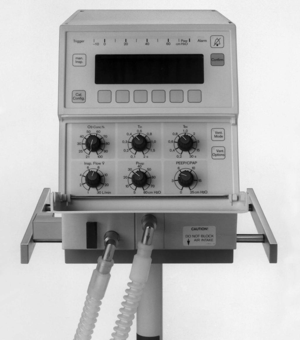
22 Operating Concept Design of the User Interface Design of the User Interface MT The ventilator front end consists of a dial panel and a display/menu key panel. Dial panel The dial panel contains buttons for the main operating modes and dial knobs for the most important ventilator parameters. 1 Green LEDs next to the dials indicate mandatory parameters in the respective operating modes. These LEDs will flash if a parameter has been internally limited or needs to be acknowledged. 2»Vent. Mode«key switches to basic ventilation mode menu 3»Vent. Options«key switches to ventilation mode extensions menu
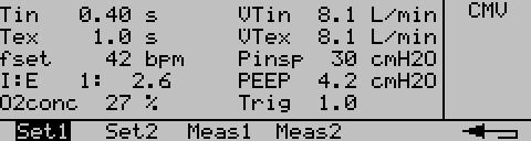
23 Operating Concept Design of the User Interface Display/menu key panel Main components of this panel are the LCD screen and a number of keys with fixed or variable function assignments. 1» g «key silences audible alarms for 2 minutes »Confirm«key is used for acknowledging alarms or to confirm settings. 5 3»Man. Insp.«key initiates manual breaths. 4»Cal. Config.«key switches to calibration menu. 5 In different screen menus, the 6 menu keys below the screen are used to select monitoring functions and ventilation modes. 6 The illuminated bar graph above the screen displays current airway pressure readings. Screen Layout 1 The graphics display window shows pressure or flow waveform or pressure-volume loops. 2 The measured values window numerically displays measured values, e.g. for MV, FiO2, Peak, Mean, PEEP. 3 The status window displays the current mode of ventilation and other status information. 4 The menu bar shows the respective function of the menu keys as symbols or text labels. In some instances, text and measured values are shown together in one larger window Messages are displayed as overlay windows on top of the current screen: Display (example): Apnea 23

24 Operating Concept Screen Menus Screen Menus Ventilation Menus 24


25 Operating Concept Screen Menus Monitoring Menus 25

26 Operating Concept Screen Menus Calibration/Configuration Menus 26
27 Preparation Contents Preparation Contents Mounting Babylog 8000 plus on Mobile Stand Mounting the Expiration Valve Installing an O2 Sensor Capsule...30 Connecting Supplies...31 Gas Supply Electrical Supply...31 Connecting a Humidifer...32 Assembling Components...33 Connecting a Patient Circuit...33 Installing an Optional Bacteria Filter...35 Installing the Wye and Flow Sensor...35 Before Using for the First Time Calibrations Calibrating the O2 Sensor Manually...39 Calibrating the Flow Sensor Exchanging a Flow Sensor Element Checks of Readiness for Operation...43 Connecting a Test Lung Testing Power Failure Alarm...43 Testing Gas Supply Failure Alarm...44 Testing CMV Testing PEEP Testing Alarm Limits Ventilator Checklist
28 Preparation Mounting Babylog 8000 plus on Mobile Stand Mounting Babylog 8000 plus on Mobile Stand Turn stand until the two lockable casters are to the right. NOTE: The following mounting instructions for Babylog assume the stand is in this position: 1 Tilt Babylog forward approximately Insert front latches into slots in platform. 1 3 Lower ventilator inserting back latches into slots in platform. Secure at the back using knurled screws. 3 2 Place tray on the ventilator - the two latches fit into the back slots in the enclosure. CAUTION! Do not place containers of liquids on top of the Babylog 8000 plus ventilator. Liquids penetrating the ventilator can cause equipment malfunction and damage. 28
29 Preparation Mounting the Expiratory Valve Mounting the Expiratory Valve Always install expiratory valve that has been cleaned and disinfected. 1 Flip lever in release position = upwards. Push expiratory valve onto guide rod as far as it will go. 1 2 Lock expiratory valve = flip lever down. 3 Connect silencer to exhaust nozzle on expiratory valve
30 Preparation Installing an O2 Sensor Capsule Installing an O2 Sensor Capsule before first use when calibration can no longer be performed. Unscrew the two screws in cover on the right and remove cover lid. Pull used O2 sensor capsule. Insert new capsule into opening - circular contacts must point towards cover lid. Babylog 8000 plus Press down cover and re-tighten the two screws. After installation: Wait for 15 minutes for sensor to warm up before calibration. Calibrate sensor manually, see page 39. Dispose of the used sensor, see page 104. Treatment of batteries and O2-sensor capsules: Do not throw into fire! Risk of explosion. Do not force open! Danger of bodily injury. Follow all local, state, and federal regulations with respect to environmental protection when disposing of batteries and O2-sensor capsules. 30
31 Preparation Connecting Supplies Connecting Supplies Gas Supply Always use medical grade oxygen and air that is dry and free from dust and oil. Contaminated gas may cause ventilator malfunction. Air O2 Supply pressures must be between 43.5 and 87 psi (3 to 6 bar) Screw high pressure air and oxygen hoses to sockets on the back panel of Babylog and insert probes into wall terminals. CAUTION! If Air and O2 supply lines are contaminated with particles or moisture, as is likely during the use with a medical air compressor, use high pressure line filters that retain at least 0.1 micron particles and stop water droplets (e.g. Dräger part no. D , D ). Air O2 Always provide adequate ventilation! When the equipment is being operated with O2, ensure that the ambient concentration does not exceed 24% O2. Otherwise, the risk of fire may be increased. Electrical Supply Line voltage must correspond to voltage range of ventilator (see rating plate on back): either : 220 V to 240 V or : 100 V to 127 V Insert Babylog power plug into wall outlet. To maintain grounding integrity, connect only to a "hospital grade" receptacle. Always disconnect supply before servicing. 31
32 Preparation Connecting a Humidifer Connecting a Humidifier Dräger cannot warrant or endorse the safe performance of third party humidifiers for use with the Babylog 8000 plus infant ventilator. Specifically, combinations of humidifiers not intended for use with infant patients bear risks of delivering breathing gas not maintained at a proper temperature. Excessive rainout in the inspiratory line of the breathing circuit may disable the flow and volume measuring capabilities of the Babylog 8000 plus ventilator. Increased pneumatic resistance and compliance in the inspiratory line caused by a humidifier may result in inaccurate airway pressure readings. We recommend contacting the manufacturers /distributors of heated humidifying devices about compliance of their products with the requested performance characteristics. Humidifiers for use with the Babylog 8000 plus ventilator: Humidifiers must conform to ISO The total resistance of the patient circuit must be less than 20 cmh2o/l/s, inspiratory resistance 12 cmh2o/l/s, expiratory resistance 8 cmh2o/l/s. The combination with the Babylog 8000 plus ventilator may not impair safety and function of either device. Prepare humidifier following its operating instructions. 32
33 Preparation Assembling Components Assembling Components Connecting a Patient Circuit Dräger cannot warrant or endorse the safe performance of third party ventilator circuits for use with the Babylog 8000 plus infant ventilator. Increased pneumatic resistance caused by some circuit systems may result in inaccurate airway pressure readings. Only use circuits with an inner diameter of at least 10 mm (0.4 inch) We recommend contacting the manufacturers /distributors of infant patient circuits regarding compliance of their products with the requested performance characteristics (see p. 32). In order to avoid any risk of electric shock in the event of faulty grounding of patient monitoring equipment, do not use antistatic or electrically conductive patient circuits* Connect patient circuit to ports on ventilator and humidifier. Use segments of appropriate length for the different application environments (see next page, suggested lengths are in meters). CAUTION! Always hold end cuffs when pulling a circuit from a port. Otherwise damage to the patient circuit will result. * IEC "Lung Ventilators" does not consider the use of antistatic or electrically conductive materials for patient circuits of a lung ventilator a contribution to increased safety. To the contrary, the use of such materials increases the risk of electric shock for the patient and the fire risk associated with oxygen. 33
34 Preparation Assembling Components Use with open care beds (outside an incubator) It is recommended to use a hinged circuit support arm with an appropriate circuit holder at the end (part no ). Swivel both nozzles on Babylog downwards or in the direction of the patient. Attach patient circuit to correct ports on the ventilator. Note suggested segment length (in meters). Note arrows for inspiratory and expiratory connector on ventilator ports. If circuit ends are confused, humidification will not be effective. 1m 1,1m 0,4m 0,25m Install water trap(s) in vertical position at the lowest point of the circuit. Use with Dräger Series 8000 incubators Install water trap(s) in vertical position at the lowest point of the circuit. Install flexible circuit support arm (order no. 2M 19630) to hold circuit inside the incubator hood. Clip both limbs of the circuit to circuit support arm. Push inspiration hose through one of the upper silicone access ports in the incubator hood. NOTE: Check that humidifier temperature probe is mounted outside the incubator. When mounted inside, the humidifier temperature control might become impaired. Follow respective humidifier operating instructions. Push expiratory limb of the circuit through the port immediately below. Use with third party incubators When used in combination with other than Dräger Series 8000 incubators, we recommend using flexible circuit support arm (order no ). It can be installed in most incubator models similar to the one for the Dräger Series 8000 incubators. 34
35 Preparation Assembling Components Installing an Optional Bacteria Filter A bacteria filter may be used as a protection against contamination of the inspiratory side of the ventilator. Use installation kit Push hose segment 0,25 m onto inspiratory port 2 Attach adapter Ø15 mm / Ø22 mm to hose. 3 Attach bacteria filter to adapter 4 Install size II ET-tube connector to bacteria filter. Install patient circuit as before. Follow instructions for use of bacteria filter Installing the Wye and Flow Sensor 1 Put sterile wye into breathing circuit. 2 Insert flow sensor (ISO connector 15 mm, part no ) into the wye, or 1 3 use wye with integrated flow sensor (part no ) 4 Connect plug on flow sensor cable to wye. Route flow sensor cable to ventilator along patient circuit. NOTE: Positioning of the wye: The connector for the endotracheal tube should be pointing approximately 45 downward to avoid buildup of condensation
36 Preparation Assembling Components Plug flow sensor cable connector into the back panel of the ventilator and tighten securing screws. 5 Connect infant size test lung (part no ) to wye. It consists of a small bellow, a 165 mm long endotracheal tube (internal dia 2.5, CH 12), and ET-tube connector. Always use safety valve when connecting sampling CO2 or NO monitors. Otherwise negative airway pressures may result in the event of a blocked inspiratory circuit. Always connect sampling lines of sidestream monitors via adapter with safety valve luer lock connector pointing upwards to avoid condensation buildup. 36

37 Preparation Before Using for the First Time Before Using for the First Time NOTE: The built-in NiCd battery for power failure alarm is recharged automatically during operation. Before first use, or when the ventilator has been out of service for a long time, the ventilator must be run for half an hour to sufficiently charge the NiCd battery. Use the following settings to avoid audible alarms during charging: 1 Set dial knob»o2-conc.%«to Set dial knob»insp. Flow *«to 5. 3 Set dial knob»tin«to 0.4,»Tex«to Set dial knob»pinsp«to Set dial knob»peep/cpap«to Press power switch button in - as far as it will go = On. 6 Display: The ventilator now tests the internal program memory. All LEDs are lit and both a continuous audible alarm and a tone sequence will sound briefly. Afterwards Display (Example): After the self test, the software version and number of operating hours are displayed. 37
38 Preparation Before Using for the First Time Calibrations 1 Press»Vent. Mode«menu key. 2 Press»CMV«menu key. Press»On«menu key. Press» «key. 2 1 Display (example): 3 The alarm limit symbol will be flashing as a request to set alarm limits. Calibrations Calibration of the built-in oxygen analyzer: - is performed automatically every 24 hours. - must be performed manually after replacing a used O2 sensor. - may be performed manually at any time. 3 Calibration of the flow sensor: - is required every time the ventilator is switched on, - after exchanging a flow sensor. Calibration of pressure sensors: - is automatic when ventilator is switched on. 38
39 Preparation Calibrations Calibrating the O2-Sensor Manually After sensor has been replaced, but possible at all times. 1 Press»Cal. Config.«menu key. 1 D Babylog 8000 plus 2 Press»O2-Cal«menu key. 2 3 After approximately 5 minutes, O2 cal disappears from the display, calibration is now completed. 3 To clear the respective text message: 1 Press»Confirm«key. D 1 Babylog 8000 plus 39
, to fine-tune measuring circuit to the particular type of sensor used. 2 Press»Sensor«menu key.")
40 Preparation Calibrations Calibrating the Flow Sensor - after ventilator is switched on, - after cleaning and disinfecting of a sensor, - after exchanging a flow sensor. 1 Press»Cal. Config.«menu key. 1 D Babylog 8000 plus For best measurement accuracy: Select type of flow sensor (ISO or Y), to fine-tune measuring circuit to the particular type of sensor used. 2 Press»Sensor«menu key. Mark display line Flow Sensor with menu keys» «, and select ISO or Y style sensor with menu keys» «or» «. 2 Select reference conditions: NTPD (ambient temperature 20 C, atmospheric pressure of 1013 mbar, dry gas), or BTPS (body temperature 37 C, ambient pressure, water vapor saturated gas). 3 Mark display line Measurement with menu keys» «, and 4 select NTPD or BTPS with menu keys» «or» «
. 1 Display: 2 Press»Start«menu key.")

41 Preparation Calibrations To calibrate: Press keys» «and» «. 1 Disconnect ET-tube and keep the patient connection of the wye sealed, e.g. using a sterile glove. NOTE: Gas flow through the wye must be completely blocked for calibration (zero flow condition). 1 Display: 2 Press»Start«menu key. After approximately 1 second, the message will disappear from the status field, the sensor is now calibrated. 2 Display: Reconnect ET-tube. If calibration could not be performed successfully: Exchange sensor element or cable, see page 42. NOTE: If the flow sensor needs to be replaced during operation but cannot be calibrated immediately, measuring accuracy may be reduced. Calibrate as soon as possible. NOTE: If flow sensor becomes momentarily disconnected, no calibration is required. 41
42 Preparation Calibrations Exchanging a Flow Sensor Element In case of message: Flow measurement disturbed Measurement switched off 1 Pull plug from flow sensor. 2 Pushing buttons on both sides simultaneously, pull flow sensor element from wye. 3 Insert new flow sensor element into the wye until it engages. Ovals engraved on flow sensor element and wye should line up. 1 Re-insert into the wye. Watch for proper orientation: groove in plug must match tongue in flow sensor. Calibrate flow sensor, see page
43 Preparation Checks of Readiness for Operation Checks of Readiness for Operation Perform each time the ventilator has been cleaned and disinfected. Completely reassemble ventilator system with accessories, please refer to pages 33 through 36. Calibrate flow sensors after switching ventilator on, see page 40. Connecting a Test Lung The test lung consists of a bellow for simulating compliance (approximately 0.5 ml/cmh2o) and an ET- tube, internal dia. 2.5 CH 12, 165 mm long, with connector, for simulating airway resistance. Testing Power Failure Alarm Disconnect power plug from wall outlet: 1 Push power switch button in back of ventilator and engage = ON. Continuous audible alarm should sound and remain at a constant volume for about 20 seconds; if not, the NiCd battery must be recharged, see page 37, "Before Using for the First Time". 2 Flip protective cap on power switch sideways. 1 Push button in fully and release = OFF: Continuous tone should now stop. Reconnect power plug


44 Preparation Checks of Readiness for Operation Testing Gas Supply Failure Alarm Push power switch button in back of ventilator and engage = ON. Switch on CMV, please refer to page 58. Set dial knob»o2-conc.%«to 60 %. Unplug probe of O2 supply hose from wall terminal. Red alarm lamp will start blinking, audible alarm will sound. Display: Re-connect O2 probe. Red alarm will stop blinking, audible alarm will stop. Unplug probe of air supply hose from wall terminal. Red alarm will start blinking, audible alarm will sound. Display: Re-connect air probe. Red alarm will stop blinking, audible alarm will stop. 44

45 Preparation Checks of Readiness for Operation Testing CMV Switch on CMV, please refer to page 58. Adjust dial knobs whose green LEDs are lit: 1»O2-Conc. %«to 21. 2»Insp. Flow *«to 10. 3»Tin«to 0.4.»Tex«to »Pinsp«to 20. 5»PEEP/CPAP«to 0. From the monitoring menu, press menu keys»peep/cpap«and»pressure« Display (example): Values displayed should be in acceptable range: PIP 18 to 22 cmh2o P 6 to 10 cmh2o PEEP 1.5 to 1.5 cmh2o Testing PEEP 6 Set knob for»peep/cpap«to 10. Confirm setting: 7 Press»Confirm«key. 7 Display (example): Values displayed should be in acceptable range: PIP 18 to 22 cmh2o P 12 to 16 cmh2o PEEP 8 to 12 cmh2o 6 45

: Apnea or MV low Airway pressure alarm limits 3 Switch on CMV, please refer to page 58.")
46 Preparation Checks of Readiness for Operation Testing Alarm Limits Apnea alarm limits 1 Switch on CPAP, please refer to page 64. Make sure that apnea alarm is enabled, please refer to page After 30 seconds (max.): 2 Red alarm will start blinking, audible alarm will sound. Display (example): Apnea or MV low Airway pressure alarm limits 3 Switch on CMV, please refer to page Block expiratory limb of the circuit (pinch). 2 Red alarm will start blinking, audible alarm will sound. Display (example): Hose kinked? or Airway pressure high Inspiration cancelled 46
: Airway pressure low or Leak in hose system? Check setting! Reset knob for»peep/cpap«to 0. Reconnect test lung.")
47 Preparation Checks of Readiness for Operation Release circuit again. Remove ET-tube connector from wye: Red alarm will start blinking, audible alarm will sound. Display (example): Airway pressure low or Leak in hose system? Check setting! Reset knob for»peep/cpap«to 0. Reconnect test lung. The ventilator is ready for operation only when: - it is completely assembled with all required auxiliary equipment in place, - all sensors are calibrated (O2, Flow), - all checks have been completed successfully. Check humidifier according to its operating instructions. 47
48 Preparation Checks of Readiness for Operation Ventilator Checklist Perform before each use of the ventilator. After exchanging a patient circuit, only checkpoints 3 through 7 are required. A copy of this checklist is provided as a writing board and should be kept attached to the ventilator. Check off each item on the check list using a pencil. Date and initial. Babylog 8000 plus Checklist Always read Operating Manual first and observe Date Babylog 8000 plus all instructions. Serial No. Use chain to attach this checklist to ventilator Signature Operational verification procedure before each use. What How Requirement 1 Gas Supply Connect high pressure Air and Oxygen hoses at the back, insert probes into wall terminals 2 Patient System Expiratory valve Patient circuit Water traps Flow sensor connector Connect test lung with tracheal tube CH 12 (2.5 mm ID) and ET-tube connector to wye. 3 Leak Test Switch Babylog 8000 plus ON. Press»Confirm«key, Set ventilation mode CPAP: Press keys»vent. Mode«,»CPAP«and»On«. Dial knobs»pinsp«to 80,»Insp. Flow *«to 2, Press»Confirm«key, Keep»man. Insp.«pressed: Hose fittings: screws tightened Connector probe: firmly inserted firmly attached complete vertical position at lowest point connected Display: Calibrate flow sensor! Bar graph pressure display: (80 ±2) cmh2o 48
49 Preparation Checks of Readiness for Operation What How Requirement 4 Function Test Flow Calibration Calibrate flow sensor. Display: Flow sensor calibrated Airway Pressure Set ventilation mode CMV, Set dial knobs:»pinsp«to 20,»Insp. Flow *«to 10,»Tin«to 0.4,»Tex«to 0.6,»PEEP/CPAP«to 0, then»peep/cpap«to 10, Press»Confirm«key. Ventilation in rhythm of set inspiratory and expiratory time. Bar graph pressure display: insp. (20 ±4) cmh2o exp. (0 ±2) cmh2o exp. (10 ±2) cmh2o 5 Apnea Monitoring Set ventilation mode CPAP: Display after max. 30 s: Apnea and audible alarm. 6 Minute Volume Monitoring 7 Airway Pressure Monitoring Set ventilation mode CMV: set lower alarm threshold for MV to 1 L/min. Reset lower alarm limit for MV: Kink expiratory limb of patient circuit: Display after max. 30 s: MV low and audible alarm. Display: Airway pressure high inspiration cancelled or Hose kinked? and audible alarm. Release expiratory limb of patient circuit, Disconnect ET-tube connector at wye: Reset dial knob»peep/cpap«to 0, Reconnect wye. Ventilation will be interrupted, pressure will drop below 5 cmh2o (pressure bar graph). After approximately 5 seconds, ventilation will start again, but will be interrupted immediately again. This sequence will repeat. Display: Airway pressure low or Leak in patient circuit? Check setting! and audible alarm. Pressure bar graph: 4 cmh2o 49
50 This page intentionally left blank 50
51 Operation Contents Operation Contents Precautions During Operation...52 Routine Checks During Operation...53 Starting Up...54 Ventilation Modes Overview Setting Ventilation Modes and Extensions Setting Trigger Volume (Trigger Sensitivity) CMV A/C...61 SIMV PSV CPAP Volume Guarantee VG Independent Expiratory Flow VIVE...67 Setting Alarm Limits Special Functions Manual Inspiration / Inspiration Hold...70 Nebulizing Aerosols...71 Displaying Waveforms and Measured Values Pressure Waveform Paw...75 Flow Waveform...75 Freezing Waveforms Displaying Measured Pressure Values Displaying Measured Values of Lung Mechanics Displaying Measured Volume Parameters Displaying Combination of Measured Values Displaying All Set Values Displaying All Measured Values...79 Displaying Trends Messages...81 Alarm Categories In the Event of an Alarm Message Log Configuration Displaying and Setting Date and Time Setting Volume of Audible Alarm Adjusting Screen Contrast Setting language for Screen Messages Analog and Digital Interface Analog Data Output Marker Signal Output Printing Transmitting Digital Data...91 Configuring Analog and Digital Interfaces...91 Shut Down
52 Operation Precautions During Operation Precautions During Operation Always use ventilator that has been cleaned and disinfected and has been successfully tested to be ready for operation. Whenever a patient is connected to the ventilator, constant attention by qualified medical staff is required in order to provide immediate corrective action in case of a malfunction. Not any and every critical condition can be expected to cause a ventilator alarm. If a fault is detected in the ventilator and its life support functions are in doubt, ventilation must be started without delay with an independent ventilation device (resuscitation bag) - using PEEP and/or increased inspiratory O2 concentration where necessary and appropriate. The unit should then be removed from use and serviced by an authorized service technician. In case of malfunction of any of the built-in monitoring a substitute must be provided in order to maintain an adequate level of monitoring. The operator of the ventilator must still assume full responsibility for proper ventilation and patient safety in all situations. This is particularly important when, during a nebulizer treatment, the Babylog flow sensor has been removed to protect it against contamination. The operator of the ventilator must still assume full responsibility for proper ventilation and patient safety when switching off flow measurement during nasal CPAP. Use appropriate external monitoring to assure patient's oxygenation status and to detect apnea. Always heed all precautions and follow all hospital protocols with respect to the administration of oxygen. It is absolutely essential that the ventilation regime and the oxygen concentration administered is selected on the basis of arterially measured oxygen partial pressure in the blood of the infant. This is the only way of minimizing the risk of both hyperoxemia, which might cause, above all, retrolental fibroplasia, and hypoxemia, which might contribute to intraventricular hemorrhage and damage to the baby's brain. The accuracy of the concentration of oxygen delivered to the patient must be monitored at all times. If the oxygen analyzer integrated into the Babylog 8000 plus ventilator is not operable, an independent oxygen monitor must be connected to the inspiratory limb of the patient circuit. Always use extreme caution when using oxygen! Oxygen intensely supports any burning! No smoking, no open fire in areas where oxygen is in use! Always provide adequate ventilation in order to maintain ambient O2 concentrations < 24 %. Always secure O2 cylinders against tipping, do not expose to extreme heat. Do not use oil or grease on O2 equipment such as tank valves or pressure regulators. Do not touch with oily hands. Risk of fire! Open and close valves slowly, with smooth turns. Do not use any tools. Do not block air intake. Ventilator malfunction will result. Be careful not to cause back pressure when using scavenging systems. 52
53 Operation Precautions During Operation Aerosol medications may clog expiratory valves which can impair ventilation. Therefore, exchange expiratory valve immediately after nebulizing aerosols. Water traps should be used in appropriate locations of the breathing circuit in order to prevent water accumulation in the tubing from being drained toward the patient's airway. Aerosol medications may clog bacteria filters which can impair ventilation. Therefore, do not use bacteria filters at the nebulizer output or in the expiratory side of the patient circuit. The wires of the Babylog 8000 plus flow sensor operate at a high temperature. If the sensor is left in the patient circuit for an extended period of time while nebulizing without cleaning, residue buildup might result from the medicated aerosols that would impair flow measurement. As a worst case, these residues might ignite! To prevent this, it is not sufficient to remove the electrical connector from the flow sensor. Therefore, it is mandatory to physically remove the flow sensor from the circuit, (resp. the flow sensor element from the wye) before beginning any nebulizer treatment. Warning or Caution level audible alarms require immediate operator attention to avert or to prevent development of situations with the possibility of patient injury. The alarm silence button is intended to provide a way of muting audible alarms while corrective action is taken. The operator of the ventilator must still assume responsibility for proper ventilator function and patient safety in the event of an alarm. Failure to identify and correct alarm situations may result in patient injury. Therapeutical decisions should not be made solely on the basis of the data transmitted via the communications Interface. Always use other diagnostic means in addition. When the flow and volume measuring system of the Babylog 8000 plus ventilator is not operable, detection of spontaneous breathing activity is not possible. Therefore no apnea alarm is provided at that time. Tidal volumes for ventilated infants are significantly influenced by the compressible volume of the breathing circuit (in addition to parameters of the patients lungs). Adjustment of inspiratory time, expiratory time, pressure limits, and inspiratory flow rate all affect the tidal volume delivered to the patient. Assessment of ventilator settings must be made with special care during periods where no patient flow/volume information is available. Otherwise, lung damage due to excessive tidal volumes and/or pressures may result. CAUTION! Use only dry and clean compressed air and oxygen. Water and/or oil in the air or oxygen supply will cause equipment malfunction and damage. CAUTION! Do not place containers of liquids on top of the Babylog 8000 plus ventilator. Liquids penetrating the ventilator can cause equipment malfunction and damage. Routine Checks During Operation About every hour, check inspiratory gas temperature. About every 2 hours, empty water traps in patient circuit. Follow hospital protocols. Periodically inspect O2 and Air inlet water traps. Drain water from bowls when necessary. 53
54 Operation Starting Up Starting Up Flip protective cap on power switch clockwise Push power switch button until it engages = On Calibrate flow sensor, see page 40. Before connecting a patient, adjust dial knobs to meet anticipated patient needs: 1»Insp. Flow *«, 2»Pinsp«, 3»PEEP«, 4»O2-Conc. %«, 5»Tin«, 6»Tex« Connect patient Estimate required tidal volume. Recommended: approximately 5 to 6 ml/kg body weight. 54
55 Operation Ventilation Modes Overview Ventilation Modes Overview Babylog 8000 plus features five main modes of ventilation that each may be modified through extensions. Some extensions are mutually exclusive while others may be combined with one another. Ventilation modes CMV Continuous Mandatory Ventilation/ Mandatory (controlled) ventilation with fixed pattern and rate without recognition of patient's spontanous breathing CPAP Continuous Positive Airway Pressure Spontaneous patient breathing with positive airway pressure A/C SIMV PSV Assist Control Ventilation Mandatory (controlled) ventilation with fixed pattern or tidal volume but synchronized with each spontaneous patient breath. Synchronized Intermittent Mandatory Ventilation Mandatory (controlled) ventilation with fixed pattern or tidal volume and rate but synchronized with spontaneous patient breathing. The patient breathes spontaneously between synchronized mandatory ventilator breaths. Pressure Support Ventilation Synchronized ventilation with preset inspiratory pressure or tidal volume. The patient determines duration and rate of inspirations. Extensions VG Volume Guarantee Volume controlled ventilation. The ventilator automatically controls inspiratory pressure to deliver the preset tidal volume. May be used with A/C, SIMV, and PSV. VIVE Variable Inspiratory and Variable Expiratory Flow Separate Continuous Flow during the expiratory cycle of mandatory ventilation. The table on the right shows all possible combinations of extensions with ventilation modes: CMV A/C SIMV PSV CPAP VG VIVE 55

56 Operation Setting Ventilation Modes and Extensions Setting Ventilation Modes and Extensions Example: To switch from CMV to SIMV with guaranteed volume VG: 1 Press»Vent. Mode«key. 1 Press»SIMV«menu key. Babylog 8000 plus continues to ventilate with CMV/IMV. Set trigger volume with menu keys» «or» «. Press»On«menu key. Babylog 8000 plus now ventilates with SIMV. Press» VG«menu key. Set desired inspiratory tidal volume VTset with menu keys» «or» «. 56

57 Operation Setting Ventilation Modes and Extensions Press»On«menu key. Babylog 8000 plus now ventilates with guaranteed tidal volume in SIMV mode. To switch off VG extension: 1 Press»Vent. Options«key. 1 Press menu keys»vg«and»off«. Leave menu: Press» «menu key. Setting Trigger Volume (Trigger Sensitivity) The trigger volume is the volume that a patient must inspire in order to trigger a ventilator breath. It is set in the ventilation modes menu or in the extensions menu. Example: Setting trigger volume in the SIMV menu. Press» «menu key for increased trigger volume (= less sensitive ). Press» «menu key for decreased trigger volume (= more sensitive ). Recommended: Start with small trigger volume (= high sensitivity). Increase trigger volume if ventilator starts autotriggering: range approximately 0.02 to 3 ml. The»Trigger«LED will be lit briefly for each triggered ventilator breath. 57
58 Operation Setting Ventilation Modes and Extensions CMV / IMV Continuous Mandatory Ventilation Intermittent Mandatory Ventilation Time cycled, pressure limited ventilation for patients without spontaneous breathing, fixed pattern - with or without pressure plateau. Switching on CMV/IMV: Press (menu) keys»vent. Mode«,»CMV«,»On«. CMV may be combined with: Separate expiratory flow VIVE, see page 69. Ventilation with a pressure plateau Inspiratory pressure is limited to Pinsp. Whenever the plateau is long enough for the flow to drop to zero at the end of inspiration, tidal volume VT is proportional to inspiratory pressure. VT = (Pinsp PEEP) C C = Compliance of patient's respiratory system Tidal volume VT is controlled by the pressure differential Pinsp PEEP. The limitation of pressure to Pinsp prevents damaging pressures, e.g. in cases of decreasing compliance. The pressure plateau facilitates diffusion of breathing gas inside the lung. Displaying the pressure waveform: Press»Graph«and»Paw«menu keys. Display (example): The dotted line in the pressure waveform represents the setting of pressure limit Pinsp. To leave this menu: Press» «key. 58
59 Operation Setting Ventilation Modes and Extensions Displaying the flow waveform: Press»Graph«and»Flow«menu keys. To leave this menu: Press» «key. Displaying measured pressure values: Press»Meas«and»Paw«menu keys. Set the desired ventilation pattern using dial knobs»pinsp«,»peep«,»tin«,»tex«and»*insp«. Displaying the measured values for volume: Press»Vol«menu key. Set dial knobs»pinsp«and»peep«in such a way that the required tidal volume VT is delivered. For setting of alarm limits for minute ventilation, please refer to page 70, 71. Ventilation without a pressure plateau This represents volume controlled ventilation. Peak inspiratory pressure results from settings of Tin and *insp. Tidal volume VT is approximately: VT = Tin *insp Crs Crs + Cc Tin *insp Crs Cc = inspiratory time, = continuous inspiratory flow, = compliance of patient's respiratory system, = compliance of patient circuit system. Tidal volume is controlled via flow and inspiratory time. 59


60 Operation Setting Ventilation Modes and Extensions Displaying the pressure waveform: Press»Graph«and»Paw«menu keys. Press» «key. Set the desired ventilation pattern using dial knobs»peep«,»tin«,»tex«and»*insp«. Displaying the flow waveform: Press»Graph«and»Flow«menu keys. Press» «key. Displaying measured pressure values: Press»Meas«and»Paw«menu keys. Displaying the measured values for volume: Press»Meas«and»Vol«menu keys. To leave this menu: Press» «key. Set dial knobs»*insp«and»tin«in such a way that the required tidal volume VT is delivered. Set dial knob»pinsp«to a threshold value that is not to be exceeded. For setting of alarm limits, please refer to page 68,

61 Operation Setting Ventilation Modes and Extensions A/C Assist Control Ventilation Ventilation with a preset pattern that is synchronous with patient's spontaneous breathing. The patient determines the ventilation rate. If a patient becomes apneic, ventilation will be performed using a rate determined by Tin and Tex settings. Switching on Assist Control: Press (menu) keys»vent. Mode«,»A/C«,»On«. Assist Control may be combined with: Guaranteed volume delivery VG, see page 66. Separate expiratory flow VIVE, see page 69. Set the desired ventilation pattern using dial knobs»pinsp«,»peep«,»tin«,»tex«and»*insp«- with or without a plateau, as with CMV. For setting a trigger volume, please refer to page 56. Adjust inspiratory time»tin«according to patient's spontaneous breathing pattern. Adjust rate of background (backup) ventilation with expiratory time»tex«. In case of auto triggering, increase trigger volume. For setting of alarm limits, please refer to page 68,
62 Operation Setting Ventilation Modes and Extensions SIMV Synchronized Intermittent Mandatory Ventilation Ventilation with fixed pattern and rate but synchronized with patient's spontaneous breathing. Patients are allowed to breathe spontaneously between ventilator breaths, but will not receive pressure support. Used for weaning patients from ventilator. If a patient becomes apneic, ventilation will be performed using a rate determined by Tin and Tex settings. Switching on SIMV: Press (menu) keys»vent. Mode«,»SIMV«,»On«. SIMV may be combined with: Guaranteed volume delivery VG, see page 66. Separate expiratory flow VIVE, see page 69. Set the desired ventilation pattern using dial knobs»pinsp«,»peep«,»tin«,»tex«and»*insp«- with or without a plateau, as with CMV - and the set ventilator rate. For setting a trigger volume, please refer to page 56. Adjust inspiratory time»tin«according to patient's spontaneous breathing pattern. In case of auto triggering, increase trigger volume. For setting of alarm limits, please refer to page 68,
63 Operation Setting Ventilation Modes and Extensions PSV (available option) Pressure Support Ventilation Pressure supported ventilation synchronous to patient's own spontaneous breathing. Patient determines both rate and duration of inspiration. A ventilator breath is terminated when inspiratory flow has dropped to approximately 15% of peak flow, at the latest after Tin. Used for spontaneously breathing patients with sufficient respiratory control, who are to be supported with an adjustable inspiratory pressure. Particularly suited for weaning. If a patient becomes apneic, ventilation will be performed using a rate determined by Tin and Tex settings. Switching on PSV: Press (menu) keys»vent. Mode«,»PSV«,»On«. PSV may be combined with: Guaranteed volume delivery VG, see page 66. Separate expiratory flow VIVE, see page 67. Set the desired ventilation pattern using dial knobs»pinsp«,»peep«, and»*insp«- with a plateau, as with CMV. Actual inspiratory time and tidal volume are displayed. Limit inspiratory time with»tin«. Set background (backup) ventilation rate with»tex«. For setting a trigger volume, please refer to page 56. In case of auto triggering, increase trigger volume. For setting of alarm limits please refer to page 68, 69. NOTE: PSV is recommended only for patients with leakage rates up to 40 % 63
 keys»vent. Mode«,»CPAP«,»On«. CPAP may be combined with: Separate expiratory flow VIVE, see page 67. Set desired CPAP level using dial knob»peep/cpap«.")

64 Operation Setting Ventilation Modes and Extensions CPAP Continuous Positive Airway Pressure Babylog 8000 plus applies a continuous flow with an airway pressure at PEEP/CPAP level. Switching on CPAP: Press (menu) keys»vent. Mode«,»CPAP«,»On«. CPAP may be combined with: Separate expiratory flow VIVE, see page 67. Set desired CPAP level using dial knob»peep/cpap«. Adjust flow according to patient needs. Displaying the flow waveform: Press»Graph«and»Flow«menu keys. To leave this menu: Press» «key. Displaying measured pressure values: Press»Meas.«and»Paw«menu keys. To leave this menu: Press» «key. Mean airway pressure should agree with the set value for PEEP/CPAP. Peak pressure and PEEP are not displayed while in CPAP mode. Set dial knob»pinsp«approximately 5 cmh2o higher than PEEP/CPAP. Displaying the measured values for volume: Press»Meas.«and»Vol«menu key. To leave this menu: Press» «key. Check spontaneously inspired volume. For setting of alarm limits, please refer to page 68,

65 Operation Setting Ventilation Modes and Extensions Nasal CPAP Monitoring of minute ventilation and for apnea is not possible due to leakage through patient's mouth. Therefore, switch off flow measurement: Unplug flow sensor cable at the wye. Display: Press»Confirm«key. Flow measurement is now switched off. The operator of the ventilator must still assume full responsibility for proper ventilation and patient safety when switching off flow measurement during nasal CPAP. Use appropriate external monitoring to assure patient's oxygenation status and to detect apnea. 65

66 Operation Setting Ventilation Modes and Extensions Volume Guarantee (Available Option) May be combined with ventilation modes CMV, SIMV, and CPAP. VG controls inspiratory plateau pressure in such a fashion between Pinsp and PEEP that the set tidal volume VTset is delivered. NOTE: VG requires that a ventilation pattern with plateau is used. Used for patients who are to be ventilated with a constant tidal volume. Switching VG on: Press key»vent. Options«. Press» VG«menu key and use menu keys» «or» «to set desired tidal volume VTset. Press»On«menu key. Tidal volume and peak pressure of mandatory breaths will now be displayed. Set ventilation pattern with a plateau using dial knobs»tin«,»tex«,»peep«, and»*insp«. Set dial knob»pinsp«to a threshold value that is not to be exceeded. To leave this menu: Press» «key. 66

67 Operation Setting Ventilation Modes and Extensions Independent Expiratory Flow VIVE VIVE (Variable Inspiratory and Variable Expiratory Flow) Expiratory continuous flow *exp may be set independently from inspiratory flow *insp. During mandatory breaths, inspiratory flow is applied. During spontaneous breathing and during CPAP, the expiratory flow is in effect. An increased inspiratory flow *insp may be used - to supply a higher flow for spontaneous breathing than the one scheduled for ventilator breaths. - to improve gas washout in the wye by increasing turbulence in the circuit system. - to allow for separate shaping of manually triggered breath in CPAP. A reduced expiratory flow *exp may be used to conserve oxygen and, thereby, reduce cost of ventilation. 1 Press»Vent. Options«key 1 Press»VIVE«menu key and use menu keys» «or» «for setting expiratory flow. Press»On«menu key and return with» «. 67
68 Operation Setting Alarm Limits Setting Alarm Limits The alarm limits for the following parameters are adjusted automatically: Airway pressure Upper alarm limit for ventilator breaths: Pinsp + 5 cmh2o Upper alarm limit for expiration or CPAP: PEEP/CPAP + 4 cmh2o Lower alarm limit: PEEP/CPAP - 2 cmh2o Lower alarm threshold for disconnection: Pinsp PEEP + PEEP 4 O2-Concentration Upper alarm limit: Lower alarm limi:»o2-conc.%«+ 4 Vol.%»O2-Conc.%«4 Vol.% For a detailed description of alarm criteria, please refer to "Technical Data", page 126. Manual setting of alarm limits is required for minute ventilation MV, apnea, and breathing rate: Lower alarm limit MV : 0 to upper alarm limit Upper alarm limit MV : from lower alarm limit to 15 L/min Alarm delay»alarm delay«: 0 to 30 seconds (delays alarms for "MV low" and "VT low") Apnea time: 5 to 20 seconds above 20 seconds = Off when very small patients are ventilated, apnea monitoring may be switched off to avoid false alarms. Use separate apnea monitoring in this case! Breathing rate (Tachypnea alarm)»tachypnea«: 20 to 200 bpm below 20 bpm = OFF 68
69 Operation Setting Alarm Limits Press menu key» «in the Monitoring menu. Display (example): Select alarm parameter with» «menu key. Adjust alarm threshold with menu keys» «or» «. Repeatedly pressing key briefly: adjustments in increments Keeping key pressed down: rapid changes. Recommendation for setting MV alarm limits. When the measured value for minute ventilation MV has reached steady state: Press»±30%«menu key. The lower alarm limit is set to 30% below actual minute volume, the upper alarm limit to 30% above actual minute volume, but it will not exceed 15 L/min. To leave menu: Press» «menu key. 69
70 Operation Special Functions Special Functions Manual Inspiration / Inspiration Hold Applicable to all modes of operation, independent of Tin and Tex settings. All other parameter settings apply. 2 1 Limit inspiratory pressure with dial knob»pinsp«. 2 Keep button pressed for the duration of desired inspiration time. Inspiration is stopped after a maximum of 5 seconds. NOTE: In this case, the next manual cycle is possible only after a delay of 5 seconds. 1 Display (example): 70
71 Operation Special Functions Nebulizing Aerosols (Available Option) Applicable in all modes of ventilation. Prerequisites: Nebulizer output port on the back panel of the ventilator and nebulizer kit Aerosol medications may clog expiratory valves which can impair ventilation. Therefore, exchange expiratory valve immediately after nebulizing aerosols. Aerosol medications may clog bacteria filters which can impair ventilation. Therefore, do not use bacteria filters at the nebulizer output or in the expiratory side of the patient circuit. Before using a nebulizer 1 Remove plug from flow sensor, acknowledge Flow sensor inop alarm on the ventilator. 1 When using the detachable ISO 15 flow sensor (part no ): 2 Pull flow sensor from the wye and 3 attach tapered tube connector directly to the wye. When using the wye with integrated flow sensor (part no ) 4 Remove flow sensor element. 5 Insert sealing plug (order no , part of nebulizer kit)
72 Operation Special Functions The wires of the Babylog 8000 plus flow sensor operate at a high temperature. If the sensor is left in the patient circuit for an extended period of time while nebulizing without cleaning, residue buildup might result from the medicated aerosols that would impair flow measurement. As a worst case, these residues might ignite! To prevent this, it is not sufficient to remove the electrical connector from the flow sensor. Therefore, it is mandatory to physically remove the flow sensor from the circuit, (resp. the flow sensor element from the flow sensor housing) before beginning any nebulizer treatment. When the flow and volume measuring system of the Babylog 8000 plus ventilator is not operable, detection of spontaneous breathing activity is not possible. Therefore no apnea alarm is provided at that time. Tidal volumes for ventilated infants are significantly influenced by the compressible volume of the breathing circuit (in addition to parameters of the patients lungs). Adjustment of inspiratory time, expiratory time, pressure limits, and inspiratory flow rate all affect the tidal volume delivered to the patient. Assessment of ventilator settings must be made with special care during periods where no patient flow/volume information is available. Otherwise, lung damage due to excessive tidal volumes and/or pressures may result. Preparation Installing the nebulizer output port connector: 1 Remove lower enclosure mounting screw on the left side of the ventilator enclosure with a coin. Attach female port connector with mounting screw. 2 Insert plug into female port in the back of the ventilator until it engages securely. 2 1 Prepare nebulizer following its Instructions for Use, open patient circuit, and install nebulizer. 3 Attach corrugated patient circuit to expiratory port of nebulizer and 4 Attach corrugated patient circuit to inspiratory port of nebulizer. Using nebulizer with incubator patients
73 Operation Special Functions Place nebulizer output port into one of the U-grommets available on most incubators for routing hoses and cables (upper location preferred if several available). Using nebulizer with patients in open beds Place nebulizer output port into circuit holder of hinged circuit support arm. Position nebulizer upright and fill. Starting nebulizer treatment 1 Connect nebulizer gas supply line to outlet port until it engages. NOTE: The nebulizer operates continuously. However, aerosol that is produced during expiration will not be transported into the patient's lungs. NOTE: The inspired O2-concentration FiO2 will be reduced since the nebulizer operates with pressurized air (2 L/min). 1 73
74 Operation Special Functions In order to maintain constant FiO2 : Increase O2-concentration for the duration of the aerosol treatment with the dial knob»o2-conc. %«using a value from the nomogram. Example: Insp. Flow * = 10 L/min O2-conc.-% = 80 Vol.% During aerosol application, set dial knob»o2-conc. %«to approximately 90 Vol.-%. resultierende resulting FiO2 FiO2 [Vol.%] O2 Vol.% Insp. Flow * [L/min] Ending nebulizer treatment 1 Retract ring on output port, connector will disengage. Remove residual medication from nebulizer, unmount nebulizer and process according to its Instructions for Use. Re-insert flow sensor element into flow sensor housing, re-attach connector plug to flow sensor. Install a cleaned and sterilized expiratory valve, see page
: 1 pressure scale 2 pressure limit»pinsp«3 time scale 2 1 4 3 4 end of Tex To leave menu: Press» «menu key. Flow Waveform From the Monitoring menu, press menu keys»graph«and»flow«.")
75 Operation Displaying Waveforms and Measured Values Displaying Waveforms and Measured Values Pressure Waveform Paw From the Monitoring menu, press menu keys»graph«and»paw«. Display (example): 1 pressure scale 2 pressure limit»pinsp«3 time scale end of Tex To leave menu: Press» «menu key. Flow Waveform From the Monitoring menu, press menu keys»graph«and»flow«. Display (example): 1 flow scale 2 baseline 3 time scale end of Tex To leave menu: Press» «menu key. 75

76 Operation Displaying Waveforms and Measured Values Freezing Waveforms From the»graph«sub-menu, press»freeze«menu key. To cancel the freeze: Press»Freeze«menu key again and the current waveform will be displayed. To leave menu: Press» «menu key. Displaying Measured Pressure Values From the Monitoring menu, press menu keys»meas.«and»paw«. Display (example): PIP P PEEP = Peak pressure of previous breath cycle = mean value of previous breath cycle = end expiratory pressure of previous breath cycle To leave menu: Press» «menu key. 76


77 Operation Displaying Waveforms and Measured Values Displaying Measured Values of Lung Mechanics Babylog 8000 plus calculates a patient's resistance and compliance using linear regression. From the Monitoring menu, press menu keys»menu«and»rc«. R = airway resistance (incl. ET-tube) C = dynamic compliance of the respiratory system TC = time constant of the respiratory system C20/C = index hinting an overdistension of the lung: C20/C < 0.8: lung may be overdistended. (only if there is no marked pressure plateau, see page 141.) r = correlation coefficient of linear regression Please refer to pages 140, 141 for a description of the calculations of above parameters. NOTE: The display of ventilation waveforms is interrupted automatically for one minute after a manual inspiration. Waveforms and respective measured values may be evaluated together. See page 75 for switching between waveforms. See page 76 for cancelling a screen freeze. If the "Attention" symbol is showing next to the value for r, the measured values may be unreliable, e.g. due to a leak. To leave menu: Press» «menu key. 77
78 Operation Displaying Waveforms and Measured Values Displaying Measured Volume Parameters From the Monitoring menu, press menu keys»meas.«and»paw«. Display (example): *E = expiratory minute ventilation spont. = percentage spontaneous breathing of total minute ventilation Leak = ET-tube leak (see description on page 138) VT = expiratory tidal volume of previous breath cycle To leave menu: Press» «menu key. Displaying Combination of Measured Values From the Monitoring menu, press menu keys»meas.«and»mv O2 P«. Display (example): *E = expiratory minute ventilation FiO2 = measured inspiratory O2 concentration Mean = Mean value of airway pressure of previous breath cycle To leave menu: Press» «menu key. 78

: For more set values: Press menu key»set2«.")

79 Operation Displaying Waveforms and Measured Values Displaying All Set Values From the Monitoring menu, press menu key»list«. All set values are displayed. Display (example): For more set values: Press menu key»set2«. Displaying all Measured Values Press menu keys»meas1«or»meas2«. All measured values are displayed. Display (example): To leave menu: Press» «menu key. 79
80 Operation Displaying Trends Displaying Trends Trends for some measured values over the previous 24 hours are stored in memory. FiO2 Inspiratory O2 concentration Mean Mean airway pressure *E Minute ventilation C Dynamic compliance R Resistance RVR* Rate Volume Ratio From the Monitoring menu, press menu key»trend«. Display (example): The diagram displays a window from the previous 24 hour period (if applicable). The size and position of the window within the time period is adjustable. Press»Param«menu key to select desired measured value. Select the size of the window with menu keys» «and» «, maximum 24 hours, minimum 2 hours. The displayed times show the beginning and end of the window. Move window with keys» «and» «. 1 Leftmost position in scroll bar: The displayed time segment is at the beginning of the recorded trend. 1 2 Rightmost position in scroll bar: The displayed time segment is at the end of the recorded trend. To leave menu: Press» «menu key. * RVR may be usd as an indicator for the likelihood of successful weaning 2 80
81 Operation Messages Messages Messages are displayed according to their urgency in a hierarchical sequence. If two alarm conditions are detected simultaneously, the more urgent one will be communicated first. Messages appear in a overlay "window" on top of the respective screen image. At the same time, one of three specific sound patterns will be used to communicate the appropriate level of urgency. Display (example): A message will disappear when the causing condition no longer exists. Alarm Categories Warning (top priority message) blinking red alarm light, intermittent audible alarm. Warning messages require immediate action to prevent a life threatening condition, e.g. when a circuit is kinked. Caution blinking red alarm LED, repetitive three tone sequence. Caution messages require short term action to prevent development of a condition with the possibility of patient injury. Respond appropriately and complete the action within 2 minutes at the most. Warning or Caution level audible alarms require immediate operator attention to avert or to prevent development of situations with the possibility of patient injury. Advisory individual three tone sequence. Advisory messages are reminders for special functions or may highlight a particular setting. D Babylog 8000 plus 81

82 Operation Messages In the Event of an Alarm To mute message and audible alarm for 30 seconds: 1 Press»Confirm«key. Each message is recorded automatically in the ventilator message log. 2 1 Silencing audible alarm for 2 minutes 2 Press»g «key. NOTE: New messages are displayed without their associated audible alarm tone during the 2-minute silencing period. To re-arm audible alarm: 2 Press»g «key again. D Babylog 8000 plus The alarm silence button is intended to provide a way of muting audible alarms while corrective action is taken. The operator of the ventilator must still assume responsibility for proper ventilator function and patient safety in the event of an alarm. Failure to identify and correct alarm situations may result in patient injury. NOTE: A troubleshooting list can be found on pages 106 to 109. Message Log Every warning, caution, and advisory message is registered in a message log. Log entries include their time of occurrence, text of the message, and an indication of whether the message had been acknowledged (normal display of message in log) or not (display of message highlighted). From the monitoring menu, press» «menu key = Log. The» «and» «menu keys allow to scroll forward and backward within the log. Display (example): To leave menu: Press» «menu key. 82
. (example: 05) Adjust setting with menu keys» «and» «.")
: Adjust volume with keys» «and» «. A test sound with the current volume level is generated for each increment.")
83 Operation Configuration Configuration Displaying and Setting Date and Time Press»Cal. Config.«key, then menu keys»config«and»clock«. Select parameter to adjust with menu keys» «or» «. Selected parameter will be highlighted (inverse). (example: 05) Adjust setting with menu keys» «and» «. Display (example): To leave menu: Press» «menu key. Setting Volume of Audible Alarms Press»Cal. Config.«key, then menu keys»config«and» l«. Display (example): Adjust volume with keys» «and» «. A test sound with the current volume level is generated for each increment. The vertical bar graph symbolizes the set volume. To leave menu: Press» «menu key. 83
: The display will show a test pattern Set optimum contrast using menu keys» «and» «.")
, Spanish, French, Italian, Dutch, Japanese, Swedish. Press»Cal. Config.")
84 Operation Configuration Adjusting Screen Contrast NOTE: Applicable only for ventilators equipped with LCD-type screen: Screen contrast can be optimized for the (vertical) viewing angle of the operator. Press»Cal. Config.«key, then menu keys»config«and»contr«. Display (example): The display will show a test pattern Set optimum contrast using menu keys» «and» «. To leave menu: Press» «menu key. NOTE: The setting will be retained after the ventilator is switched off. Setting Language for Screen Messages Available languages are: American English, German, English (UK), Spanish, French, Italian, Dutch, Japanese, Swedish. Press»Cal. Config.«key, then menu keys»config«and»lang«. Display (example): Select language using menu keys» «and» «. To leave menu: Press» «menu key. NOTE: The setting will be retained after the ventilator is switched off. 84
85 Operation Analog and Digital Interface Analog and Digital Interface (Available Option) Interface provides analog output of measured values, output of data reports, communication with patient monitors or personal computers, e.g. with EvitaView PC software, allowing graphic and numeric display of ventilation parameters. Therapeutical decisions should not be made solely on the basis of the data transmitted via the communications interface. Always use other diagnostic means in addition. Place connected devices in the same room with the Babylog 8000 plus ventilator, but at a distance of at least 1.5 m (5 ft) from the patient.* The two analog outputs supply each one of the available measured values. The RS 232 serial interface outputs information to a printer: - reports - trend information - waveform data or transmits data to a patient monitor or a personal computer. The marker output indicates certain events: - triggered mandatory breath - mandatory breath - alarm. Analog Data Output The two analog outputs Analog 1 and Analog 2 each provide one measured value, e.g. VT, Paw, Flow.... Voltage range: 0 to 10 V. Connect recorder (impedance 1 MΩ) with interface cable (see also Technical Data, page 127). Select signal and range, see page 92. * Requirement pursuant EN Analog1 Analog2 85
86 Operation Analog and Digital Interface Marker Signal Output The logic pulse at the marker output indicates events during ventilation, e.g. each mandatory breath or triggered mandatory breath. The voltage output is always either H(igh) or L(ow). (Please refer also to Technical Data, page127.) Depending on the configuration, the pulses are issued as follows: Mandatory breath High signal during mandatory breaths, Low signal otherwise. Triggered mandatory breath: High signal during triggered mandatory breaths only, Low signal otherwise. Alarm conditions: Low signal during an alarm condition, High signal otherwise. H L H L H L Mandatory Breath Mandatory Breath Trigger Alarm Connect recorder (impedance 1 MΩ) with interface cable Select signal, please refer to "Configuring Marker Output", page 93. Analog1 Analog2 Printing NOTE: The printer driver for the serial interface is designed for use with HP Thinkjet compatible printers. For use with other printers please consult Dräger first. Connect printer with interface cable NOTE: For proper function, configuration of RS 232 interfaces of printer and Babylog 8000 plus must match. Configure RS 232 interface, please refer to page 93. Analog1 Analog2 86
87 Operation Analog and Digital Interface Press»Cal. Config.«key. Press»Print«menu key Display (example): Printing Reports For documenting measured, set, and status values. Example: : CMV Babylog 8000 plus Settings: Measurements: TI: 0,82 s Pinsp: 33,0 cmh2o FiO2: 21 % Mean: 15,0 cmh2o TE: 1,59 s PEEP: 6,1 cmh2o Leak: 0 % PIP : 33,5 cmh2o I:E: 1: 2,0 FiO2: 21 % spont: 0 % PEEP: 6,0 cmh2o fset: 24,9 bpm f: 25,0 bpm Flow in: 8,4 L/min VT: 24 ml Flow ex: 8,4 L/min MV: 0,58 L/min TIspont: -,-- s VG: LFT: VTset: --,- ml C: 1,22 ml/mbar R: 408 cmh2o/l/s C20/C: 3,37 TC: 499 ms VIVE: off Trigger: 1,3 Flow measurement: NTPD Y FiO2-compensated For printing a single report: Press»Select«menu key, until»report«is highlighted. Press»Start«button. The function of the button changes to»stop«. NOTE: While a report is being printed, the functions»print all«and»babylink«are not available. However, any of the other functions can be started. Babylog will execute them after finishing the report. To abort printing: Press»Stop«button. 87

88 Operation Analog and Digital Interface To print a report automatically every 30 minutes: Press»Select«button until»30 min. report«is highlighted. Press»Start«button. The function of the button changes to»stop«. Printing trend information For graphical printing of trend memory contents. The currently active window (size and position within the 24 hour range) is used. Press»Select«button repeatedly, until»trend«is highlighted. Press»Start«button. The function of the button changes to»stop«. Example: 88
89 Operation Analog and Digital Interface To abort printing: Press»Stop«button. Printing waveforms For graphics printout of the three waveforms: Airway pressure Flow Volume Press»Select«button repeatedly, until»graphics«is highlighted. Press»Start«button. The function of the button changes to»stop«. To abort printing: Press»Stop«button. Example: 89
90 Operation Analog and Digital Interface Printing all For printing report, trend information, and waveforms. Press»Select«button repeatedly, until»all«is highlighted. Press»Start«button. The function of the button changes to»stop«. To abort printing: Press»Stop«button. 90

: Selecting signals and ranges for Analog1 and Analog2 Press»Param«menu key repeatedly, until»analog1«is highlighted. Select desired signal for analog output with menu keys» «or» «.")
91 Operation Analog and Digital Interface Transmitting Digital Data For connecting digital data recording devices (patient monitor, PC), using the Dräger "BabyLink" data transmission protocol. Connect device with interface cable Press»Select«button repeatedly, until»babylink«is highlighted. Press»Start«button. The function of the button changes to»stop«. To abort data transmission: Press»Stop«button. Configuring Analog and Digital Interfaces For configuring the RS232 interface, the analog outputs, and the marker output. Press»Cal. Config.«key, then menu keys»config«and»com«. Display (Example): Selecting signals and ranges for Analog1 and Analog2 Press»Param«menu key repeatedly, until»analog1«is highlighted. Select desired signal for analog output with menu keys» «or» «. Press menu key»param«to highlight range selection, then select parameter range with menu keys» «or» «. Proceed in the same way for Analog2. NOTE: The setting will be retained after the ventilator is switched off. 91
92 Operation Analog and Digital Interface The following signals and ranges are available: Airway pressure cmh2o > V Airway pressure cmh2o > V Mean airway pressure cmh2o > V Mean airway pressure cmh2o > V FiO Vol.-% > V Flow L/min > V Flow L/min > V Flow L/min > V Flow L/min > V Volume ml > V Volume ml > V Volume ml > V Volume ml > V Tidal Volume ml > V Tidal Volume ml > V Tidal Volume ml > V Tidal Volume ml > V Minute Ventilation *E L/min > V Minute Ventilation *E L/min > V Minute Ventilation *E L/min > V Minute Ventilation *E L/min > V MVim L/min > V MVim L/min > V MVim L/min > V MVim L/min > V VTim ml > V VTim ml > V VTim ml > V VTim ml > V VTHF ml > V VTHF ml > V DCO ml 2 /s > V DCO ml 2 /s > V Continuous Flow L/min > V (set value) Leak % > V Spontaneous fraction of *E % > V Default settings: Analog1: Flow Analog2: Airway pressure L/min cmh2o 92

93 Operation Analog and Digital Interface To select default settings during operation: Press»*/P«menu key. NOTE: If a measured value exceeds the set range, the output voltage will be clipped. NOTE: The setting will be retained after the ventilator is switched off. Configuring the marker output Press»Param«menu key repeatedly, until» «is highlighted. Select desired signal for analog output with menu keys» «or» «: triggered mandatory breath or mandatory breath or alarm condition. Default setting: mandatory breath. NOTE: The setting will be retained after the ventilator is switched off. Configuring RS232 interface To select data transmission rate (baud rate) and parity check mode. Press»Param«menu key repeatedly, until»baud rate«is highlighted. Select the baud rate with menu keys» «or» «: 9600, 2400, or 1200 Select»Parity» using»param«menu key. 93
94 Operation Analog and Digital Interface Select parity check mode using» «or» «: NONE or EVEN or ODD. NOTE: When using a printer, select NONE. Factory default settings: Baud rate: 9600 Parity: NONE Stop bits 1 (fixed) Data bits 8 (fixed) To leave menu: Press» «menu key. NOTE: The setting will be retained after the ventilator is switched off. Configuring the printer If a HP ThinkJet printer is used, it must be configured as follows (see Owner's Manual for HP ThinkJet): Baud rate: same as Babylog 8000 plus Parity: NONE Data bits: 8 Handshake mode: XON/XOFF Alternate Control Sequence Mode 94
95 Operation Shut Down Shut-Down After disconnecting patient At the back panel: 1 Flip protective cap on power switch clockwise. 2 Push button in fully and release = OFF. Switch off humidifier. Disconnect all electrical and pneumatic supplies. Empty water traps in gas supply lines
96 This page intentionally left blank 96
97 Care Care Contents Dissasembly Removing Components Disinfecting/Cleaning/Sterilizing Reassembly Assembling the Flow Sensor Maintenance Maintenance Intervals In Case of Ventilator Malfunction User Replaceable Parts Operating Instructions Babylog 8000 plus SW 5, USA 3rd. ed. 97
98 Care Disassembly Disassembly Clean and process ventilator after each patient. Always follow accepted hospital procedures for handling equipment contaminated with body fluids. Patient breathing circuit Note: The following description refers to a disposable circuit system. Refer to humidifier operating instructions for disassembly of humidifier components. Empty water trap in expiratory limb, if necessary. Unplug connector of flow sensor at the wye and at the back of ventilator. Remove breathing circuits from flexible circuit support arm in the incubator or from hinged arm. Detach circuit from ports on ventilator. Detach flow senor. Detach temperature sensor(s) from circuit, disconnect cable from humidifier unit. Remove sensor element from flow sensor: Press buttons on both sides of flow sensor element and gently remove insert from wye. Removing the Expiratory Valve 1 Push lever upward (release position). 2 Pull expiration valve out (forward). 1 D 2 Babylog 8000 plus Operating Instructions Babylog 8000 plus SW 5, USA 3rd. ed. 98
99 Care Disinfecting/Cleaning/Sterilizing Disinfecting/Cleaning/Sterilizing CAUTION! Certain components of the ventilator consist of materials that are sensitive to certain organic solvents sometimes used for cleaning and disinfecting (e.g., phenols, halogen releasing compounds, oxygen releasing compounds, strong organic acids, etc.). Exposure to such substances may cause damage that is not always immediately apparent. Sterilization with ethylene oxide (EtO) is also not recommended. To prevent any damage, we recommend that only detergents and disinfectants are used that are compatible with the device, e.g. surface disinfectants on the basis of aldehydes or quarternary ammonium compounds for disinfection. Ensure that all disinfectants are registered with the U.S. Environmental Protection Agency for use as intended. Always follow the instruction labels specifically with respect to prescribed concentrations and the necessary exposure times. Disinfectants often contain besides their main active agents additives that can also damage materials. When in doubt, ask the supplier/manufacturer of the disinfectant/ cleaning agent. For a list of materials used in the ventilator, please refer to page 128. Follow all accepted hospital procedures for disinfecting parts contaminated by body fluids (protective clothing, eyewear, etc.). Operating Instructions Babylog 8000 plus SW 5, USA 3rd. ed. Babylog 8000 plus ventilator, mobile stand, cables Disinfection procedure: Wipe disinfection 99
100 Care Disinfecting/Cleaning/Sterilizing Flow sensor element Disinfection procedure: Bath disinfection CAUTION! Do not process flow sensor element in cleaning and disinfection equipment. Do not use compressed air, a brush or similar tools to clean flow sensor element as this would possibly damage the thin wires in the flow sensor. NOTE: Residual mucus dried in the wye shortens life of the flow sensor, therefore proceed with bath disinfection immediately after use. Rinse flow sensor element in distilled water. Thoroughly shake off residual water. After disinfection, autoclave at 134 C (273 F). Expiratory valve, flow sensor (without sensor element) Disinfection procedure: Bath disinfection Rinse with clear water - preferably soft running water - shake off residual water. After disinfection, dry expiratory valve completely. We recommend drying by sterilizing in an autoclave at 134 C (273 F). CAUTION! Ensure that no liquid remains in the control and measuring canals of the expiratory valve, as it might cause malfunction. Humidifier components Follow respective operating instructions for cleaning and disinfection of these items. Operating Instructions Babylog 8000 plus SW 5, USA 3rd. ed. 100
101 Care Reassembly Reassembly Assembling the Flow Sensor 1 Insert flow sensor element into wye or flow sensor until it engages. The oval marks must line up. 1 Connect plug to flow sensor, note orientation (tongue and groove). Assemble equipment as described starting on page 29, "Preparation". After switching on: Calibrate flow sensor, see page 40. Check readiness for operation, see page 43. The ventilator is only ready for operation when it has been completely assembled and the flow sensor been calibrated after switching the ventilator on. Operating Instructions Babylog 8000 plus SW 5, USA 3rd. ed. 101
102 Care Maintenance Maintenance CAUTION! The device must be inspected and serviced at regular 6 month intervals. A record must be kept on this preventive maintenance. We recommend obtaining a service contract with DrägerService through your vendor. For repairs of the Babylog 8000 plus infant ventilators, we recommend that you contact DrägerService. To avoid any risk of infection, clean and disinfect ventilator and accessories before any maintenance according to established hospital procedures - this applies also when returning ventilators or parts for repair. Preventive Maintenance work on the Babylog 8000 plus ventilator shall be performed by trained and factory authorized staff only. Maintenance Intervals O2 sensor capsule Cooling-air intake filter Lip seals of patient block receptacle plate Lithium battery for data backup Replace sensor capsule in event of display message: O2 measurement inop, see page 30. For disposal of sensor capsule, see page 104. Clean or replace after 4 weeks, see page 103. Replace at least every year. Disposal with normal domestic waste. To be replaced by trained service personnel every 2 years To be replaced by trained service personnel every 2 years. For disposal, see page 104. Pressure reducer Complete overhaul every 6 years by DrägerService. Preventive maintenance Every 6 months by trained and service service personnel. Disconnect power! Before opening the unit, always disconnect plug at the wall outlet first. Operating Instructions Babylog 8000 plus SW 5, USA 3rd. ed. 102
103 Care In Case of Ventilator Malfunction User Replaceable Parts In Case of Ventilator Malfunction Never operate the ventilator if it has suffered physical damage or does not seem to operate properly. In this case always refer servicing to properly trained and factory authorized service personnel. For ventilators with liquid crystal displays (LCD): If, in case of damage to the ventilator, the glass of the LCD screen is broken, a liquid chemical may escape that should not come into contact with the skin. In case of contamination, wash off with soap immediately. User-Replaceable Parts Replacing cooling air intake filter Clean or replace after 4 weeks. Replace after 1 year at the latest. Remove air intake filter from its holder in the back of the ventilator. Replace or clean in warm water with detergent added. Dry well. Re-insert cooling-air filter into holder. Verify that it is fit properly. Dispose of used cooling-air filter with domestic waste. Operating Instructions Babylog 8000 plus SW 5, USA 3rd. ed. 103
104 Care User Replaceable Parts Disposal of batteries and O2 sensors Treatment of batteries and O2-sensor capsules: Do not throw into fire! Risk of explosion. Do not force open! Danger of bodily injury. Follow all local, state, and federal regulations with respect to environmental protection when disposing of batteries and O2-sensor capsules. Batteries must be disposed of as special waste. Dispose of O2 sensors in the same way as batteries. Information may be obtained from local environmental and public health authorities or from approved waste disposal companies. Operating Instructions Babylog 8000 plus SW 5, USA 3rd. ed. 104
105 Troubleshooting Contents Troubleshooting Contents Troubleshooting Operating Instructions Babylog 8000 plus SW 5, USA 3rd. ed. 105
106 Troubleshooting Troubleshooting Babylog 8000 plus displays alarm messages at 3 levels of priority: Warning = Message with top priority Caution = Message with medium priority Advisory = Message with low priority In the table below, the messages are listed in alphabetical order. The table should help you to identify the cause of an alarm and to ensure rapid remedy of the problem. Message Cause Remedy Airway pressure high Exp. valve opened Airway pressure high Inspiration cancelled Pressure increase in patient circuit. Expiratory valve has been opened to relieve pressure from system. Ventilator faulty. Pressure increase in patient circuit. Ventilator breath has been cancelled to relieve pressure from system. Ventilator faulty. Check patient condition, Check ventilation pattern, Correct alarm limit if necessary. Take ventilator out of service. Check patient condition, Check ventilation pattern, Correct alarm limit if necessary. Take ventilator out of service. Airway pressure low Leak or disconnection. Check patient circuit for leaks. Apnea Inspiratory or expiratory flow set too low. Patient's spontaneous breathing has stopped. Increase flow. Apply controlled ventilation. Calibrate flow sensor! Dirty flow sensor Please clean sensor! After switching ventilator on or after a power out, the ventilator will ask for flow sensor calibration. Without calibration, no flow is measured! Liquid in flow sensor. Press»Confirm«key and calibrate flow sensor, page 40. Simply press»confirm«if ventilator is to be used without flow measurement. WARNING It remains the responsibility of the operator to maintain adequate minute ventilation and other parameters. Exchange sensor insert. Fault in rotary knob Ventilator faulty. Take ventilator out of service. FiO2 high O2 measurement faulty. Calibrate O2 sensor manually, page 39. Blender faulty. Take ventilator out of service. Operating Instructions Babylog 8000 plus SW 5, USA 3rd. ed. 106
107 Troubleshooting Message Cause Remedy FiO2 low Flow measurement disturbed Meas. switched off Flow measurement disturbed VG uses Pinsp, Check settings! O2 sensor not calibrated. Blender faulty. Flow sensor faulty or disconnected. Flow measurement faulty. Faulty cable. Due to faulty or disconnected flow sensor, VG is disabled. Flow measurement faulty. Calibrate O2 sensor manually, page 39. Take ventilator out of service. Connect flow sensor or cable, calibrate flow sensor, page 40. Exchange flow sensor. Exchange cable. Connect flow sensor or cable,calibrate flow sensor, page 40. Exchange flow sensor. Frequency high! Hyperventilation Adjust ventilator rate Hose kinked? I:E maximum 3:1! IRV! Leak in hose system? Check setting! Kink in patient circuit. Blockage or condensation in circuit. ID of patient circuit too small. With knobs for Tin and Tex, an I:E ratio > 3:1 was set. The range of settings is limited to 3:1. With knobs for Tin and Tex, an I:E ratio of 1:1 was set (Inverse Ratio Ventilation). Leak or disconnection. Check patient circuit. Clear passage. Use circuit with less resistance. Check setting of Tin and Tex, and change to obtain an acceptable ratio. Press»Confirm«key to acknowledge or check settings of Tin and Tex, and change as necessary. Check patient circuit for leaks. Operating Instructions Babylog 8000 plus SW 5, USA 3rd. ed. Set value for Pinsp too high. Check set value for Pinsp. Loss of stored data Ventilator malfunction. Take ventilator out of service. Max. frequency 150 bpm Ventilation rate set via Tin and Tex exceeds 150 bpm. Check Tin and Tex settings. Medical air pressure low Air supply pressure too low. Make sure pressure is greater than 3 bar (43.5 psi). Medical air supply pressure measurement out of range Faulty pressure sensor. Faulty pressure regulator. Take ventilator out of service. 107
108 Troubleshooting Message Cause Remedy MV high MV low O2 calibration Meas. switched off O2 calibration unstable Check supply pressures Lung compliance has increased. Resistance has decreased. Hyperventilation. Ventilator malfunction. Lung compliance has decreased. Resistance has increased. Low spontaneous breathing. Large ET-tube leak. Ventilator malfunction. Calibration in progress. Fault during calibration. Check ventilation settings and adjust as necessary. Take ventilator out of service. Check ventilation settings and adjust as necessary Take ventilator out of service. Press»Confirm«key to acknowledge. Repeat manual calibration of O2 sensor page 39. Take ventilator out of service. O2 measurement disturbed Faulty FiO2 measurement. Exchange O2 sensor, page 30. Take ventilator out of service. O2 measurement out of range Exchange sensor! O2 sensor faulty or used up. Exchange O2 sensor, page 30. O2 supply pressure low O2 supply pressure to low. Make sure pressure is greater than 3 bar (45 psi). O2 supply pressure measurement out of range Faulty pressure sensor. Faulty pressure regulator. Take ventilator out of service. PEEP > 8 cmh2o? Press Confirm! Knob for Pinsp was set at a value above 8 cmh2o, while setting was limited to 8 cmh2o.. Press»Confirm«key. The limitation of 8 cmh2o is cancelled PEEP minimum 3 cmh2o! Pinsp > 40 cmh2o? Press Confirm! Pinsp/PEEP Check set values! A PEEP lower than 3 cmh2o has been set during high frequency ventilation. PEEP/CPAP is limited to the 3 cmh2o minimum. knob for Pinsp was set at a value above 40 cmh2o, while setting was limited to 40 cmh2o. Pinsp setting less than 5 cmh2o above set PEEP. PEEP would be limited by Pinsp Set PEEP to value of at least 3 cmh2o. Press»Confirm«key. The limitation of 40 cmh2o is cancelled. Increase Pinsp and/or reduce PEEP. Operating Instructions Babylog 8000 plus SW 5, USA 3rd. ed. 108
109 Troubleshooting Message Cause Remedy Pressure measurement out of range Printing cancelled Check printer! Re-calibrate flow sensor if exchanged! Liquid in patient block. Condensation in patient circuit. Fault in pressure measurement function. ID of patient circuit too small Printer switched off. No paper. Faulty cable. RS232 interface of ventilator or printer not properly configured. During operation: Flow sensor has been exchanged. Replace patient block Remove condensation. Take ventilator out of service. Use circuit with less resistance. Switch on printer. Load paper. Replace cable. Configure RS232 interface, see page 93, 94. Press»Confirm«key. Calibrate flow sensor, page 40. VT low Check settings! Cable was disconnected and re-connected. Set tidal volume VTset has not been delivered. Press»Confirm«key. Increase inspiratory flow *insp, increase inspiratory time, increase Pinsp if necessary. Tube obstructed? Kinked or blocked tube. Clear passage. Ventilator malfunction Error code: xxx Auto-triggering Ventilator faulty. Correct trigger sensitivity. Take ventilator out of service. Operating Instructions Babylog 8000 plus SW 5, USA 3rd. ed. 109
110 This page intentionally left blank Operating Instructions Babylog 8000 plus SW 5, USA 3rd. ed. 110
111 What's What Contents What's What Contents Dial Panel Display and Menu Key Panel Front Connections Back Panel Labels Abbreviations and Symbols Symbols Operating Instructions Babylog 8000 plus SW 5, USA 3rd. ed. 111

112 What'sWhat Dial Panel MT Dial Panel 1.1 Dial knob for inspiratory O2-concentration»O2-Conc.%«1.2 Dial knob»insp. Flow *«1.3 Dial knob for inspiratory time»tin«1.4 Dial knob for limiting inspiratory pressure»pinsp«1.5 Dial knob for expiratory time»tex«1.6 Dial knob»peep/cpap«1.7»vent. Options«key for ventilation mode extensions 1.8»Vent. Mode«key for ventilation modes 1.9»man. Insp.«key for starting or extending a manual inspiration Operating Instructions Babylog 8000 plus SW 5, USA 3rd. ed. 112
113 What's What Display and Menu Key Panel MT Operating Instructions Babylog 8000 plus SW 5, USA 3rd. ed. 2 Display and Menu Key Panel 2.1 Key for selecting»cal. Config.«menu 2.2 Yellow»Trigger«LED lights when inspiration is started by trigger. 2.3 Screen for numeric and waveform displays 2.4 Bargraph display for airway pressure Paw 2.5 Red alarm light flashes for "Warning/Caution" messages to direct attention to the screen. 2.6»g «key for silencing audible alarm for about 2 min 2.7»Confirm«key for acknowledging messages and for checking LEDs and audible alarms 2.8 Menu keys 113
114 What'sWhat Front Connections MT Front Connections 3.1 Silencer (for ejector) 3.2 Lever for locking expiratory valve (patient block) 3.3 Expiratory port 3.4 Inspiratory port Operating Instructions Babylog 8000 plus SW 5, USA 3rd. ed. 114
 4.3 Grounding pin 4.4 DISS O2 inlet 4.5 DISS Air inlet 4.6 Connector for flow sensor 4.7 Cooling fan air filter 4.")
115 What's What Back Panel MT Operating Instructions Babylog 8000 plus SW 5, USA 3rd. ed. 4 Back Panel 4.1 Power switch 4.2 Line power fuses (2x) 4.3 Grounding pin 4.4 DISS O2 inlet 4.5 DISS Air inlet 4.6 Connector for flow sensor 4.7 Cooling fan air filter 4.8 Communications Interface connections (available option) 115

116 What's What Labels 5 Labels 5.1 Main CAUTION/WARNING label 5.1 DANGER! RISK OF EXPLOSION IF USED IN THE PRESENCE OF FLAMMABLE ANESTHETICS DISCONNECT SUPPLY BEFORE SERVICING REPAIRS ON THIS EQUIPMENT TO BE PERFORMED ONLY BY DrägerService OR ITS AUTHORIZED SERVICE CENTERS CAUTION! TO MAINTAIN GROUNDING INTEGRITY, CONNECT ONLY TO A "HOSPITAL GRADE" RECEPTACLE TO REDUCE RISK OF ELECTRIC SHOCK, DO NOT REMOVE COVER USE ONLY DRY AND CLEAN COMPRESSED AIR AND OXYGEN. WATER IN GAS SUPPLY CAN CAUSE EQUIPMENT MALFUNCTION FEDERAL LAW AND REGULATIONS IN THE USA AND CANADA RESTRICT THIS DEVICE TO SALE BY OR ON THE ORDER OF A PHYSICIAN 5.2 Air Intake CAUTION label CAUTION! DO NOT BLOCK AIR INTAKE 5.2 Operating Instructions Babylog 8000 plus SW 5, USA 3rd. ed. 116
RAM 4021 Operation Manual
 RAM 4021 Operation Manual Worldwide Manufacturer of Gas Detection Solutions TABLE OF CONTENTS RAM 4021 For your safety...3 Description...3 Set-up mode...4 Annunciator lights/alarms...4 Operation...5 Calibration...6
AUTOVENT 4000 VENTILATOR
 OVERVIEW AUTOVENT 4000 Only properly trained and approved Escambia County Bureau of Public Safety Paramedics are to use the AutoVent 4000 ventilator manufactured by LSP to transport patients already on
RAM Operation Manual. Worldwide Manufacturer of Gas Detection Solutions
 RAM 4021 Operation Manual Worldwide Manufacturer of Gas Detection Solutions TABLE OF CONTENTS RAM 4021 For Your Safety... 2 Description.... 2 Setup Mode.... 2 Lights/Alarms.... 3 Operation.... 4 Calibration....
CPR MEDICAL DEVICES INC. OPERATING MANUAL FOR RESUSCITATOR
 CPR MEDICAL DEVICES INC. OPERATING MANUAL FOR OXYLATOR FR-300 RESUSCITATOR Symbols used in the Operating Manual for the Oxylator FR-300 and/or on the Oxylator FR-300 unit: WARNING! Do not use grease or
AND OPERATION INSTRUCTIONS
 ADI 2111-D Certified ISO 9001 MEDICAL FLOWMETER (Back Pressure Compensated Thorpe Tube) INSTALLATION AND OPERATION INSTRUCTIONS Before Installing or Operating, Read and Comply with These Instructions Controls
RAM 4021-PR. Operation Manual. Worldwide Manufacturer of Gas Detection Solutions
 RAM 4021-PR Operation Manual Worldwide Manufacturer of Gas Detection Solutions TABLE OF CONTENTS RAM 4021-PR For Your Safety... 2 Description.... 2 Setup Mode.... 2 Lights/Alarms.... 3 Operation.... 4
RAM 4021-DPX Operation Manual
 RAM 4021-DPX Operation Manual Worldwide Manufacturer of Gas Detection Solutions TABLE OF CONTENTS ABL 4021-DPX / RAM 4021-DPX For Your Safety... 3 Description... 3 Setup Mode... 4 Lights/Alarms... 4 Operation...
AC1810 / AC1810-A TECHNICAL SPECIFICATIONS. Operating Pressure psi ( kgs/cm²) [AC1810] Displacement. Net Weight
![AC1810 / AC1810-A TECHNICAL SPECIFICATIONS. Operating Pressure psi ( kgs/cm²) [AC1810] Displacement. Net Weight](/thumbs/83/88369739.jpg "AC1810 / AC1810-A TECHNICAL SPECIFICATIONS. Operating Pressure psi ( kgs/cm²) [AC1810] Displacement. Net Weight") Technical Specifications Operating Instructions Maintenance Information Troubleshooting Guide Parts Diagrams AC1810 / AC1810-A THE EVOLUTION OF PERFECTION CAUTION: Before attempting to use or service this
Technical Specifications Operating Instructions Maintenance Information Troubleshooting Guide Parts Diagrams AC1810 / AC1810-A THE EVOLUTION OF PERFECTION CAUTION: Before attempting to use or service this
RAM Operation Manual
 RAM 4021-1 Operation Manual Worldwide Manufacturer of Gas Detection Solutions TABLE OF CONTENTS RAM 4021-1 For Your Safety... 2 Description... 2 Setup Mode... 3 Lights/Alarms... 3 Operation... 4 Calibration...
USER MANUAL SAVE THESE INSTRUCTIONS. For the most current manual revision, please visit our Website:
 USER MANUAL Model: PM4300 Series SAVE THESE INSTRUCTIONS For the most current manual revision, please visit our Website: www.precisionmedical.com 300 Held Drive Tel: (+001) 610-262-6090 Northampton, PA
Operation and Maintenance of the EPV200 Portable Ventilator
 Operation and Maintenance of the EPV200 Portable Ventilator 1 Applications of the EPV200 The EPV200 Portable Ventilator is a gas powered electronically controlled mechanical ventilator, designed to provide
RAM Operation Manual. Worldwide Manufacturer of Gas Detection Solutions
 RAM 4021 Operation Manual Worldwide Manufacturer of Gas Detection Solutions TABLE OF CONTENTS RAM 4021 For Your Safety... 2 Description.... 2 Setup Mode.... 2 Lights/Alarms.... 3 Operation.... 4 Calibration....
Model ASSEMBLY and OPERATING INSTRUCTIONS
 QUICK CHANGE AIR BRUSH KIT Model 93506 ASSEMBLY and OPERATING INSTRUCTIONS Due to continuing improvements, actual product may differ slightly from the product described herein. 3491 Mission Oaks Blvd.,
MODEL Maverick Heavy Duty Aerosol Compressor Operator s Manual
 MODEL 50012 Maverick Heavy Duty Aerosol Compressor Operator s Manual This page left blank intentionally CONTENTS Page No. INSPECTION... 1 GENERAL INFORMATION... 1 SAFETY PRECAUTIONS... 2 BASIC OPERATING
Compact Triple Cabinet Outlet Station Model Installation and Operating Instructions
 Compact Triple Cabinet Outlet Station Model 6258-1 Installation and Operating Instructions The Porter Compact Triple Outlet Station (6258-1) provides a quick, safe, and reliable method of connection to
Table of Contents. Operating Instructions. Resource v.2 Conserving Regulator
 Operating Instructions Table of Contents Resource v.2 Conserving Regulator Safety Information Device Precautions Introduction Product Features Product Specifications Feature Illustrations Set Up Usage
SPECIFICATIONS APCEPH1
 APCEPH1 ph CONTROLLER SPECIFICATIONS APCEPH1 Input voltage 120 Volts AC Maximum amperage 14.5 amps @ 120 VAC ph Accuracy +/- 0.2 ph ph Control range Adjustable 4.5 8.5 ph Weight < 1 lbs Dimensions 3" x
R E D I C O N T R O L S
 R E D I C O N T R O L S Operation & Maintenance Manual Portable Service Purger for Low Pressure Chillers Model: PSP-LP-1B For Refrigerants R-11, R-113, R-114 & R-123 & Other Similar Refrigerants File Literature
The Crossvent 2i+ 2. Ventilator Concept (brief theory of operation and features)
") The Crossvent 2i+ 1. How is this ventilator classified 2. Ventilator Concept (brief theory of operation and features) -Your Two Choices with this Ventilator 3. An overview of the device (an in-service)
The Crossvent 2i+ 1. How is this ventilator classified 2. Ventilator Concept (brief theory of operation and features) -Your Two Choices with this Ventilator 3. An overview of the device (an in-service)
Compact Triple Cabinet Outlet Station Model B Installation and Operating Instructions
 PORTER Parker Hannifin Corporation Porter Instrument Division 245 Township Line Rd. P.O. Box 907 Hatfield, PA 19440-0907 USA (215) 723-4000 / fax (215) 723-5106 Compact Triple Cabinet Outlet Station Model
MACS Mask CPAP System
 The MACS CPAP delivery system is under US patent protection as part of the pneuton Ventilator (Patent # 6,591,835) MACS Mask CPAP System Manufactured by: Airon Corporation 129 West Hibiscus Boulevard Suite
120 PSI FAST-FILL AIR SOURCE KIT 25% Duty Compressor on 1.5 Gallon Air Tank
 120 PSI FAST-FILL AIR SOURCE KIT 25% Duty Compressor on 1.5 Gallon Air Tank PART NO. 20003 IMPORTANT: It is essential that you and any other operator of this product read and understand the contents of
CPR MEDICAL DEVICES INC. OPERATING MANUAL
 CPR MEDICAL DEVICES INC. OPERATING MANUAL FOR OXYLATOR EMX RESUSCITATION AND INHALATION SYSTEM Symbols used in the Operating Manual for the OXYLATOR EMX and/or on the OXYLATOR EMX unit: WARNING! Do not
Yoke Block Instruction Manual
 Yoke Block Instruction Manual ! WARNING IMPORTANT: READ MANUAL COMPLETELY BEFORE OPERATING THIS DEVICE This manual contains instructions on periodically required checks to be performed by the user. These
SATURN EVO COLOR A N A E S T H E S I A S Y S T E M. Manufacturer of high quality anaesthesia products
 Saturn Evo SATURN EVO COLOR A N A E S T H E S I A S Y S T E M i n t e l l i g e n t s i m p l i c i t y Manufacturer of high quality anaesthesia products SATURN EVO COLOR PATIENT SAFETY AND USER PATIENT
Yoke Block Instruction Manual
 Yoke Block Instruction Manual ! WARNING IMPORTANT: READ MANUAL COMPLETELY BEFORE OPERATING THIS DEVICE This manual contains instructions on periodically required checks to be performed by the user. These
200 PSI HIGH-FLOW AIR SOURCE KIT
 200 PSI HIGH-FLOW AIR SOURCE KIT 50% Duty Compressor on 2.0 Gallon Air Tank PART NO. 20008 IMPORTANT: It is essential that you and any other operator of this product read and understand the contents of
Complex Care Hub Manual: Pressure Ventilation on the LTV 1200
 Complex Care Hub Manual: Pressure Ventilation on the LTV 1200 Table of Contents 1 Mechanical Ventilation... 3 2 Important information for support worker... 3 3 Commonly used terms... 3 3.1 Inspiration...
DRAFT U S E R M A N U A L CAUTION. Model: 19MFA1001 Series. Federal (USA) law restricts this device to sale by or on the order of a physician.
 law restricts this device to sale by or on the order of a physician.") U S E R M A N U A L Model: 19MFA1001 Series SAVE THESE INSTRUCTIONS Federal (USA) law restricts this device to sale by or on the order of a physician. 300 Held Drive Tel: (+001) 610-262-6090 Northampton,
U S E R M A N U A L Model: 19MFA1001 Series SAVE THESE INSTRUCTIONS Federal (USA) law restricts this device to sale by or on the order of a physician. 300 Held Drive Tel: (+001) 610-262-6090 Northampton,
MODEL NUMBER: PSI AIR SOURCE KIT 200 PSI Compressor on 2.0 Gallon 200 PSI Air Tank
 IMPORTANT SAFETY INSTRUCTIONS CAUTION - To reduce risk of electrical shock or Electrocution: MODEL NUMBER: 20008 200 PSI AIR SOURCE KIT 200 PSI Compressor on 2.0 Gallon 200 PSI Air Tank IMPORTANT: It is
AIR/OXYGEN BLENDER INSTRUCTION MANUAL
 BIO-MED DEVICES AIR/OXYGEN BLENDER INSTRUCTION MANUAL CATALOG #2120 REV 042203 BIO-MED DEVICES INC. 1445 BOSTON POST ROAD, GUILFORD, CT 06437 (203) 458-0202 FAX (203) 458-0440 www.biomeddevices.com TABLE
200 PSI FAST-FILL AIR SOURCE KIT
 200 PSI FAST-FILL AIR SOURCE KIT 55% Duty Compressor on 2.0 Gallon Air Tank PART NO. 20007 IMPORTANT: It is essential that you and any other operator of this product read and understand the contents of
Instruction Manual LIMITED 1 YEAR WARRANTY. Hydraulic Punch Driver Read this material before using this product.
 Instruction Manual Hydraulic Punch Driver 902-483 LIMITED 1 YEAR WARRANTY We make every effort to assure that its products meet high quality and durability standards, and warrant to the original purchaser
2 CYLINDER MOBILE CART USER S MANUAL / INSTRUCTIONS
 Parker Hannifin Corporation Precision Fluidics Division Porter Instrument 245 Township Line Road Hatfield, PA 9440 Office 25-723-4000/Fax 25-723-506 www.porterinstrument.com 2 CYLINDER MOBILE CART USER
Technical Data and Specifications
 Technical Data and Specifications INTENDED USE Ventilator designed to provide Invasive and Non-invasive ventilation for the critical care management of adult, pediatric and neonate-infant (including premature)
MODEL NUMBER: M20005 AIR SOURCE KIT. 30% Duty Compressor on. 2.0 Gallon Air Tank SAVE THIS MANUAL FOR FUTURE REFERENCE
 MODEL NUMBER: M20005 AIR SOURCE KIT 30% Duty Compressor on 2.0 Gallon Air Tank SAVE THIS MANUAL FOR FUTURE REFERENCE USER MANUAL IMPORTANT SAFETY INSTRUCTIONS CAUTION - To reduce risk of electrical shock
USER MANUAL FLOW SELECTOR PM1000 SAVE THESE INSTRUCTIONS. Federal (USA) law restricts this device to sale by or on the order of a physician.
 law restricts this device to sale by or on the order of a physician.") USER MANUAL FLOW SELECTOR PM1000 SAVE THESE INSTRUCTIONS CAUTION Federal (USA) law restricts this device to sale by or on the order of a physician. RECEIVING / INSPECTION Remove the Precision Medical,
USER MANUAL FLOW SELECTOR PM1000 SAVE THESE INSTRUCTIONS CAUTION Federal (USA) law restricts this device to sale by or on the order of a physician. RECEIVING / INSPECTION Remove the Precision Medical,
OPERATOR S MANUAL Ar-Gone Weld Gas Analyzer
 July 2011 OPERATOR S MANUAL Ar-Gone Weld Gas Analyzer WARNING! Before operating this product, read and understand this Operator s Manual. Become familiar with the potential hazards of this unit. Contact
Operating Instructions for BAIR22-6 AIR-POWERED CRIMPING TOOL
 Operating Instructions for BAIR22-6 AIR-POWERED CRIMPING TOOL Read and understand all of the instructions and safety information in this manual before operating or servicing this tool. Table of Contents
450P AUTOMATIC PORTABLE COMPRESSOR EXTREME SERIES
 EXTREME SERIES PART NO. 45043 IMPORTANT: It is essential that you and any other operator of this product read and understand the contents of this manual before installing and using this product. SAVE THIS
U S E R M A N U A L CAUTION. SAVE THESE INSTRUCTIONS Federal (USA) law restricts this device to sale by or on the order of a physician.
 law restricts this device to sale by or on the order of a physician.") U S E R M A N U A L 1600 SERIES OXYGEN REGULATOR 168715G (Shown) SAVE THESE INSTRUCTIONS Federal (USA) law restricts this device to sale by or on the order of a physician. 300 Held Drive Tel: (+001) 610-262-6090
U S E R M A N U A L 1600 SERIES OXYGEN REGULATOR 168715G (Shown) SAVE THESE INSTRUCTIONS Federal (USA) law restricts this device to sale by or on the order of a physician. 300 Held Drive Tel: (+001) 610-262-6090
SSFU SUPER SPRAYFAST UNIVERSAL ADHESIVE APPLICATOR
 S S F U SSFU SUPER SPRAYFAST UNIVERSAL ADHESIVE APPLICATOR MACHINERY DIVISION OWNER S MANUAL UNIT INSTRUCTIONS Please follow all SSFU Safety Instructions. Contact your Duro Dyne Tech Service if you have
CPX EMERGENCY STANDBY MANIFOLD INSTALLATION, OPERATIONS & MAINTENANCE MANUAL
 CPX EMERGENCY STANDBY MANIFOLD INSTALLATION, OPERATIONS & MAINTENANCE MANUAL Company Registered Office: Crown House, Stockport, Cheshire, SK13RB No. 850 0700 67 Registered in England and Wales No. 05058855
SLE4000. Infant Ventilator with touch-screen operation. When the smallest thing matters
 SLE4000 Infant Ventilator with touch-screen operation When the smallest thing matters SLE4000 - The Total Solution for Conventional Infant Ventilation SLE is a world leader in the design and manufacture
97C COMPRESSOR KIT 12V PART NO C COMPRESSOR KIT 24V PART NO C COMPRESSOR KIT PART NO
 97C COMPRESSOR KIT 12V PART NO. 00097 97C COMPRESSOR KIT 24V PART NO. 02497 98C COMPRESSOR KIT PART NO. 00098 97C 98C IMPORTANT: It is essential that you and any other operator of this product read and
453 Series Steam Heated Vaporizing Regulator
 ADI 0453A Certified ISO 9001:2000 453 Series Steam Heated Vaporizing Regulator INSTALLATION AND OPERATION INSTRUCTIONS Before Installing or Operating, Read and Comply with These Instructions Controls Corporation
INSTRUCTION MANUAL MP4AR Remote Convection Gauge Range: 1 x 10⁻³ Torr to 1 x 10+3 Torr
 INSTRUCTION MANUAL MP4AR Remote Convection Gauge Range: 1 x 10⁻³ Torr to 1 x 10+3 Torr A DIVISION OF THE FREDERICKS COMPANY 2400 PHILMONT AVE. HUNTINGDONVALLEY, PA 19006 PARTS LIST 1 3 4 2 # QTY ITEM DESCRIPTION
Operating Manual. Model 25200B/25202B Refrigerant Recovery Unit. (Not for use in automotive R-134a applications)
") Operating Manual Model 25200B/25202B Refrigerant Recovery Unit (Not for use in automotive R-134a applications) ROBINAIR Refrigerant Recovery Unit Model: 25200B /25202B Series Type of Equipment: Recovery
Operating Manual Model 25200B/25202B Refrigerant Recovery Unit (Not for use in automotive R-134a applications) ROBINAIR Refrigerant Recovery Unit Model: 25200B /25202B Series Type of Equipment: Recovery
INSTALLATION. and INSTRUCTION MANUAL. for QUALITY AIR BREATHING SYSTEMS. Model 50-P-Mini Portable Systems Outfitted with ABM-725 Monitor
 INSTALLATION and INSTRUCTION MANUAL for QUALITY AIR BREATHING SYSTEMS Model 50-P-Mini Portable Systems Outfitted with ABM-725 Monitor M A R T E C H S E R V I C E S C O M P A N Y P.O. Box 7079 OFFICE: (507)
MANUAL DIRECT PURGE OPTION. UNION Instruments GmbH CWD2005 PLUS. General information, safety standards and regulations for direct purge option
 MANUAL DIRECT PURGE OPTION UNION Instruments GmbH CWD2005 PLUS General information, safety standards and regulations for direct purge option Version: V1.00 Stand: 24.03.2010 Union Instruments GmbH Zeppelinstr.
Portable Gas Monitor GX User Maintenance Manual (H4-0050)
") H4E-0050 Portable Gas Monitor GX-8000 User Maintenance Manual (H4-0050) Need of Maintenance and Servicing This gas monitor must be maintained in a normal state at all times to prevent accidents due to
H4E-0050 Portable Gas Monitor GX-8000 User Maintenance Manual (H4-0050) Need of Maintenance and Servicing This gas monitor must be maintained in a normal state at all times to prevent accidents due to
MODEL NUMBER: P-A AUTOMATIC PORTABLE COMPRESSOR
 MODEL NUMBER: 45043-450P-A AUTOMATIC PORTABLE COMPRESSOR IMPORTANT: It is essential that you and any other operator of the product read and understand the contents of this manual before installing and
Babylog 8000 plus. Intensive Care Ventilator for Neonates Software 5.n Instructions for Use
 Babylog 8000 plus WARNING: For a full understanding of the performance characteristics of this medical device, the user should carefully read these Instructions for Use before use of the medical device.
User Instruction Manual
 User Instruction Manual 4500 psi Air Compressor Ver 2, 1.18 Contents Parts Included...3 Assembly Instructions...3-5 Operation Instructions...6-7 Oil Change Intervals...8 Air Filter Replacement...9 Setting
PERSONAL AIR BREATHING UNIT
 PERSONAL AIR BREATHING UNIT Operation & Maintenance Manual MARTECH SERVICES C O M P A N Y 1-800-831-1525 Table of Contents INTRODUCTION: Page 2 COMPONENTS DRAWING: Page 3 START UP: Page 4 OPERATION: Page
450P- RV AUTOMATIC PORTABLE COMPRESSOR EXTREME SERIES
 450P- RV AUTOMATIC PORTABLE COMPRESSOR EXTREME SERIES PART NO. 45053 IMPORTANT: It is essential that you and any other operator of this product read and understand the contents of this manual before installing
E2K-L. Liquid Level Sensor That Is Unaffected by the Color of the Pipe or Liquid. Liquid Level Sensor. Ordering Information
 Liquid Level EK-L CSM_EK-L_DS_E 3 Liquid Level That Is Unaffected by the Color of the or Liquid Mount to bypass pipes. Fit a wide range of pipe diameters: 8 to mm or to mm Built-in Amplifiers to save space.
Operation and Maintenance of the MCV100 and MCV100-B Portable Ventilator
 Operation and Maintenance of the MCV100 and MCV100-B Portable Ventilator 1 Applications of the MCV100(B) The MCV100 and MCV100-B Mass Casualty Ventilators are electronically controlled portable ventilators,
PC7-C Flowmeter O2/N2O Sedation Unit Instruction Manual
 PC7-C Flowmeter O2/N2O Sedation Unit Instruction Manual ! WARNING IMPORTANT: READ MANUAL COMPLETELY BEFORE OPERATING THIS DEVICE This manual contains instructions on periodically required checks to be
AIR COMPRESSOR. Failure to follow all instructions as listed below may result in electrical shock, fire, and/or serious personal injury.
 2 GALLON AIR COMPRESSOR Model: 7517 DO NOT RETURN TO STORE. Please CALL 800-348-5004 for parts and service. CALIFORNIA PROPOSITION 65 WARNING: You can create dust when you cut, sand, drill or grind materials
BOC: Living healthcare. Manual. LIV IQ BOC Integrated Valve with digital display portable delivery system for Medical Oxygen. BOC: Living healthcare
 BOC: Living healthcare Manual LIV IQ BOC Integrated Valve with digital display portable delivery system for Medical Oxygen. BOC: Living healthcare 02 Manual LIV IQ Oxygen Manual LIV IQ Oxygen 03 Contents.
Flow meter. bellow vaporizer. APL valve. Scavenging system
 Introductory Lecture Series: The Anesthesia Machine PORNSIRI WANNADILOK Objectives Anesthesia Machine Ventilators Scavenging Systems System Checkout 1 Flow meter ventilator bellow vaporizer Corrugated
SIX R (P ) AND SEVEN R (P ) POSITION CYLINDERS Service Information
 AND SEVEN R (P ) POSITION CYLINDERS Service Information") SIX R431006322 (P -063892-00001) AND SEVEN R431006321 (P -063981--00002) POSITION CYLINDERS Service Information The six and seven position cylinders are medium duty pneumatic positioning devices that operate
SIX R431006322 (P -063892-00001) AND SEVEN R431006321 (P -063981--00002) POSITION CYLINDERS Service Information The six and seven position cylinders are medium duty pneumatic positioning devices that operate
INSTALLATION MANUAL Matheson Tri-Gas Cabinet Enclosures
 INSTALLATION MANUAL Matheson Tri-Gas Cabinet Enclosures MINT-0289-XX TABLE OF CONTENTS Limited Warranty... 3 User Responsibility... 3-4 General Service... 4 Safety Precautions.... 5 Physical Dimensions..
S/5 Aespire. Quick Reference Guide
 S/5 Aespire Quick Reference Guide Anesthesia system controls 1 Turn on the system 2 7100 controls and monitored data 3 Menu map 4 Set the ventilation mode 5 Set ventilator controls 6 Vaporizer controls
Operation Manual. Pro CO 2 Analyzer. Carbon Dioxide Analyzer. Rev
 Operation Manual Pro CO 2 Analyzer Carbon Dioxide Analyzer Rev. 10.17 Quick Reference Guide READ ENTIRE MANUAL BEFORE USE 1. To switch on, hold the On/Off button until the display powers up. 2. To turn
INSTRUCTIONS FOR MODEL SG6500 GAS HEATERS
 INSTRUCTIONS FOR MODEL SG6500 GAS HEATERS THIS BOOKLET CONTAINS PROPRIETARY INFORMATION OF ADVANCED SPECIALTY GAS EQUIPMENT CORP. AND IS PROVIDED TO THE PURCHASER SOLELY FOR USE IN CONJUNCTION WITH MODEL
Operation Manual. Pro CO. Carbon Monoxide Analyzer. Rev
 Operation Manual Pro CO Carbon Monoxide Analyzer Rev. 10.17 Quick Reference Guide READ ENTIRE MANUAL BEFORE USE 1. To switch on, hold the On/Off button until the display powers up. 2. To turn off, hold
USER MANUAL SAVE THESE INSTRUCTIONS. 300 Held Drive Tel: (+001) Northampton, PA USA Fax: (+001) ISO Certified
 Northampton, PA USA Fax: (+001) ISO Certified") USER MANUAL Model: PM4300 Series (PM4351 Shown) SAVE THESE INSTRUCTIONS Federal (USA) law restricts this device to sale by or on the order of a physician. 300 Held Drive Tel: (+001) 610-262-6090 Northampton,
USER MANUAL Model: PM4300 Series (PM4351 Shown) SAVE THESE INSTRUCTIONS Federal (USA) law restricts this device to sale by or on the order of a physician. 300 Held Drive Tel: (+001) 610-262-6090 Northampton,
GETZ EQUIPMENT INNOVATORS PART NO.: 9G59554 MODEL: MS 36 SC-R HYDROSTATIC TEST PUMP
 GETZ EQUIPMENT INNOVATORS PART NO.: 9G59554 MODEL: MS 36 SC-R HYDROSTATIC TEST PUMP LIMITED WARRANTY Getz Equipment Innovators warrants its products, and component parts of any product manufactured by
User Manual 1 P a g e Rev. V1.6-EN 11/08/2014
 User Manual 1 P a g e Rev. V1.6-EN 11/08/2014 Copyright Disclaimer Trademarks and patents Intended use Contact info 2011 Inflotrolix, Inc. This document may not be copied in whole or in part or otherwise
Equinox II USER MANUAL NITROUS OXIDE/ OXYGEN 50%/50% USER ADMINISTRATION SYSTEM 01EQ7000E DEMAND VALVE 01EQ7001E TABLE OF CONTENTS
 TM controlled ventilation Equinox II NITROUS OXIDE/ OXYGEN 50%/50% ADMINISTRATION SYSTEM 01EQ7000E DEMAND VALVE 01EQ7001E USER TABLE OF CONTENTS CHAPTER TITLE PAGE 1 INTRODUCTION 1.1 Equinox II Administration
INSTRUCTIONS FOR MODELS SG3897 AND SG3898 CROSS PURGE ASSEMBLIES
 INSTRUCTIONS FOR MODELS SG3897 AND SG3898 CROSS PURGE ASSEMBLIES THIS BOOKLET CONTAINS PROPRIETARY INFORMATION OF ADVANCED SPECIALTY GAS EQUIPMENT CORP. AND IS PROVIDED TO THE PURCHASER SOLELY FOR USE
Med Aire Alternating Pressure Pump and Pad System
 User Manual Med Aire Alternating Pressure Pump and Pad System 14002E 14001E Symbols & Statements NOTE Indicates some tips or some information users should be aware of. CAUTION Indicates correct operating
2015 Hamilton Medical AG. All rights reserved. Printed in Switzerland.
 HAMILTON-T1 Quick Guide This Quick Guide is intended as a useful reference for ventilation of adult and pediatric patients. It does not replace the clinical judgment of a physician or the content of the
U S E R M A N U A L AIR FLOWMETER. MODELS: 1MFA2001 (shown) 1MFA9001 CAUTION. ISO Certified
 1MFA9001 CAUTION. ISO Certified") U S E R M A N U A L AIR FLOWMETER MODELS: 1MFA2001 (shown) 1MFA9001 ISO 13485 Certified Authorized Your EU local Representative: distributor: EMERGO EUROPE, INC. Molenstraat 15 2513866 BH -624 The -3952
U S E R M A N U A L AIR FLOWMETER MODELS: 1MFA2001 (shown) 1MFA9001 ISO 13485 Certified Authorized Your EU local Representative: distributor: EMERGO EUROPE, INC. Molenstraat 15 2513866 BH -624 The -3952
SC505 Sof Care Inflator. Operating Instructions and Service Manual
 SC505 Sof Care Inflator Gaymar Industries, Inc. 10 Centre Drive Orchard Park, NY 14127 Toll Free +1 800.828.7341 + 1 716.662.2551 Fax +1 800.993.7890 Outside USA +1 716.662.8636 Outside USA Fax +1 716.662.0730
4-in-1 Professional Inflator Kit
 4-in-1 Professional Inflator Kit Owner s Manual WARNING: Read carefully and understand all ASSEMBLY AND OPERATION INSTRUCTIONS before operating. Failure to follow the safety rules and other basic safety
The centerpiece of a comprehensive anaesthesia workstation
 The centerpiece of a comprehensive anaesthesia workstation IntelliSave AX700 anaesthesia machine A slim design with rich functionality The IntelliSave AX700 is a comprehensive anaesthesia machine from
ACRYLIC FLOW METERS 0-30, 0-70 & LPM
 ACRYLIC FLOW METERS 0-30, 0-70 & 0-120 LPM ASSEMBLY INSTRUCTIONS & INSTRUCTIONS FOR USE R219P86 (0-120LPM) R219P87 (0-70LPM) R219P88 (0-30 LPM) R138P11 Rev. D TABLE OF CONTENTS: 1.0 PRODUCT OVERVIEW...1
STANDARD OPERATING PROCEDURES DIVISION OF COMPARATIVE MEDICINE UNIVERSITY OF SOUTH FLORIDA
 STANDARD OPERATING PROCEDURES DIVISION OF COMPARATIVE MEDICINE UNIVERSITY OF SOUTH FLORIDA SOP#: 1157.1 Date Issued: 05/14 Date Revised: 5/15 Page 1 of 6 TITLE: SCOPE: RESPONSIBILITY: PURPOSE: SurgiVet
Blendox AII5000F Inhalation Antalgic System. User s Manual :SP-Y Series No. Version :A1. Date of Review:
 AII5000F Inhalation Antalgic System User s Manual Series No. :SP-Y53564 Version :A1 Date of Review:2012-04-29 To Users: Welcome to Blendox AII5000F Inhalation Antalgic System (hereafter referred to as
3 GALLON, OILLESS PANCAKE COMPRESSOR INSTRUCTIONS. Item #31289
 3 GALLON, OILLESS PANCAKE COMPRESSOR INSTRUCTIONS Item #31289 The EASTWOOD 3 GALLON, OILLESS PANCAKE COMPRESSOR, with an Integral Air Regulator, efficiently supplies all compressed air requirements for
ASSISTANCE. Cardinal Health Pulmonetic Systems Medina Rd., Suite 100 Minneapolis, Minnesota
 ASSISTANCE Cardinal Health Pulmonetic Systems 17400 Medina Rd., Suite 100 Minneapolis, Minnesota 55447-1341 Customer Care: (800) 754-1914 (763) 398-8500 Fax: (763) 398-8403 Website: www.cardinalhealth.com/viasys
AIR INLINE METAL SHEAR
 AIR INLINE METAL SHEAR ASSEMBLY and OPERATING INSTRUCTIONS 3491 Mission Oaks Blvd. / Camarillo, CA 93011 Copyright 1997 by Harbor Freight Tools. All rights reserved. No portion of this manual or any artwork
AIR COMPRESSOR OPERATING INSTRUCTION AND PARTS LIST
 AIR COMPRESSOR OPERATING INSTRUCTION AND PARTS LIST OIL-LESS TYPE IMPORTANT: PLEASE READ CAREFULLY BEFORE STARTING OPERATIONS. THE CONTENTS ARE FOR GENERAL INFORMATION OF ALL THE SIMILAR MODELS. Record
Operation of Oxylog 3000 ventilator
 Operation of Oxylog 3000 ventilator Overview Suitable for patients from approximately 7Kg body weight upwards (smallest tidal volume 50mls). Entirely power dependant- will not ventilate if no available
VENTI-O 2 plus. O 2 switching valve for: VENTImotion from serial number 4000 VENTIlogic from serial number 4000 VENTImotion 2
 VENTI-O 2 plus O 2 switching valve for: VENTImotion from serial number 4000 VENTIlogic from serial number 4000 VENTImotion 2 Device description and operating instructions Overview VENTI-O 2 plus with therapy
U S E R M A N U A L. Model: PM4300 Series SAVE THESE INSTRUCTIONS
 U S E R M A N U A L Model: PM4300 Series (PM4351 Shown) SAVE THESE INSTRUCTIONS CAUTION Federal (USA) law restricts this device to sale by or on the order of a physician. 300 Held Drive Tel: (+001) 610-262-6090
42045 Heavy Duty ADA Base Model Kit: 85/105 PSI (ADA Compressor Only) Heavy Duty ADA Base Model Kit: 110/145 PSI (ADA Compressor Only)
 Heavy Duty ADA Base Model Kit: 110/145 PSI (ADA Compressor Only)") 42045 Heavy Duty ADA Base Model Kit: 85/105 PSI (ADA Compressor Only) 42047 Heavy Duty ADA Base Model Kit: 110/145 PSI (ADA Compressor Only) 45052 Constant Duty ADA Base Model Kit: 85/105 PSI (ADA Compressor
42045 Heavy Duty ADA Base Model Kit: 85/105 PSI (ADA Compressor Only) 42047 Heavy Duty ADA Base Model Kit: 110/145 PSI (ADA Compressor Only) 45052 Constant Duty ADA Base Model Kit: 85/105 PSI (ADA Compressor
Equinox II USER MANUAL NITROUS OXIDE/ OXYGEN 50%/50% ADMINISTRATION SYSTEM (01EQ7000E) DEMAND VALVE (01EQ7001E) O-TWO MEDICAL TECHNOLOGIES INC.
 DEMAND VALVE (01EQ7001E) O-TWO MEDICAL TECHNOLOGIES INC.") MANUFACTURERS AND DISTRIBUTORS OF: O-Two eseries Electronic Transport Ventilators O-Two Single Use Open CPAP Systems O-Two CAREvent Range of Automatic Transport Ventilators O-Two CAREvent Range of Automatic
MANUFACTURERS AND DISTRIBUTORS OF: O-Two eseries Electronic Transport Ventilators O-Two Single Use Open CPAP Systems O-Two CAREvent Range of Automatic Transport Ventilators O-Two CAREvent Range of Automatic
Budget Range Operators Handbook
 Budget Range Operators Handbook BAMBI AIR COMPRESSORS LTD 152 Thimble Mill Lane Heartlands Birmingham B7 5HT United Kingdom Tel: 0121 322 2299 Fax: 0121 322 2297 Email: sales@bambi-air.co.uk www.bambi-air.co.uk
Adult/Pediatric Demonstration Lung Model. User s Manual
 Adult/Pediatric Demonstration Lung Model User s Manual IngMar Medical, Ltd. This page intentionally left blank 2 Legal Information Product Warranty Educational tools and test instruments manufactured or
444C DUAL PERFORMANCE VALUE PACK
 (Chrome) PART NO. 44432 IMPORTANT: It is essential that you and any other operator of this product read and understand the contents of this manual before installing and using this product. SAVE THIS MANUAL
Operation Manual. O2 Quickstick. Oxygen Analyzer 08.17
 Operation Manual O2 Quickstick Oxygen Analyzer 08.17 If you have any questions on this equipment please contact Technical Support at: Nuvair 1600 Beacon Place Oxnard, CA 93033 Phone: 805-815-4044 FAX:
ROPV R40 E Series User Manual
 HARBIN ROPV INDUSTRY DEVELOPMENT CENTER ROPV R40 E Series User Manual For Use with the Following ROPV Pressure Vessel Models: R40 300E R40 450E Headquarters Tel:(+86)451-82267301 Fax:(+86)451-82267303
How Ventilators Work. Chapter 3
 How Ventilators Work Chapter 3 To care for a ventilator patient, you need to know: The various functions of the ventilator used How the ventilator interacts with the patient How changes in lung condition
e700 Automatic Transport Ventilator User Manual e700 User Manual (15PL Rev.14 28_8_2017)
") e700 Automatic Transport Ventilator User Manual Table of Contents Chapter 1 Safety... 1 Chapter 2 Intended Use.. 4 Chapter 3 Overview.... 5 3.1 Control and Display Layout...... 5 3.2 Function Keys......
e700 Automatic Transport Ventilator User Manual Table of Contents Chapter 1 Safety... 1 Chapter 2 Intended Use.. 4 Chapter 3 Overview.... 5 3.1 Control and Display Layout...... 5 3.2 Function Keys......
AMP Oil Free Manual AMP 50-8-TC AMP 50-6-D AMP General User and Maintenance Instructions
 AMP Oil Free Manual AMP 50-8-TC AMP 50-6-D AMP 50-24 General User and Maintenance Instructions Silentaire Technology 8614 Veterans Memorial Dr. Houston, TX 77088 800-972-7668 Fax 832-327-0669 www.silentaire.com
E X R A D I N Spherical Ion Chambers A3. A4 REF DOC #
 E X R A D I N Spherical Ion Chambers A3. A4 REF 92717. 92715 R DOC #80360-00 E X R A D I N Spherical Ion Chambers A3. A4 REF 92717. 92715 STANDARD IMAGING INC. 7601 Murphy Drive Middleton, WI 53562 TEL