DESIGN OF AN EFFECTIVE LOW PRESSURE VAV AIR DISTRIBUTION SYSTEM
|
|
|
- Gerard Bailey
- 5 years ago
- Views:
Transcription


1
2 ABSTRACT The aim of this paper is to provide the air conditioning engineer with a clear set of guidelines for use in the design of the air distribution system for a low pressure Variable Air Volume system. The following aspects are considered: 1. Different types of terminal outlets and why some work better than others. 2. A brief comparison between pressure-dependent and pressureindependent systems. 3. Duct design and methods of sizing. 4. The static regain principle and duct static pressure control. The principles involved in the subject of air movement are not always clearly understood by air conditioning engineers. This paper aims to provide guidelines, which will help the engineer avoid the common pitfalls that often result in a system that does not live up to expectation. Thirty years ago dual duct systems were common and although they were not at all energy or cost efficient, they worked well because they were generally over-engineered and could cope with almost any condition, climatic or occupancy related. Today s systems need to be much more effective in terms of cost, energy consumption and indoor air quality. Occupants of modern buildings are also more demanding and have higher expectations of the environmental control system. To meet this demand, the air conditioning engineer needs to develop a better understanding of the theory and practice of VAV systems. This paper, therefore, seeks to provide the information necessary to design a top class, effective air distribution system, a vital link in the chain of requirements for the complete installation to be successful. 5. Commissioning procedures. In considering these aspects, practical guidelines for good design and installation are provided. The paper also highlights many of the common pitfalls, which may result in a system which does not live up to expectation. Keywords: & Diffusers. Variable Air Volume, Air Distribution, Static Pressure 2. COMPARISON OFTWO MAIN TYPES OF VAV SYSTEMS As a means of briefly comparing the two common types of VAV systems, only the components, advantages and disadvantages will be considered. Although by no means comprehensive, this comparison should highlight the salient differences between the two systems Pressure Independent System 1. INTRODUCTION A properly designed, installed and commissioned Variable Air Volume (VAV) system can be one of the most energy efficient and comfortable systems for occupied zones. Indoor air quality, noise and overall comfort are generally excellent with a system that performs as it is meant to. VAV technology has the distinct advantage of flexibility and adaptability that no other system can offer. However, systems do not always work as they should and this could be due to any number of reasons. It is important to note however that the shortcomings of the applied VAV technology are not intrinsic or generic, and they should have limited impact if the design, installation and operation of the system are properly addressed. In almost all cases, problems and complaints result from errors or omissions in the design, construction and operation of the system. These can and should be corrected Essential Components The more conventional VAV system, also known as a single duct, pressure independent system, consists of the following Cooling/Heating coils, filters etc, items common to all types of A/C systems Supply air fan, often with variable speed control, capable of providing duct pressures, at the fan discharge, in the region of 500Pa to 1500Pa Supply air ducting, designed for medium pressure and relatively high velocities Volume control terminal units that serve occupied zones by distributing the supply air through a group (typically 2 to 8) of fixed aperture outlets A temperature controller, which will control the supply air quantity for a particular zone, to satisfy the cooling/heating demand for that zone. This paper addresses specifically the subject of AIR DISTRIBUTION, although it is difficult to treat the subject of air distribution without getting quickly involved with the system itself. But, because time and space do not allow, this discussion will be restricted to matters pertaining to air distribution only Advantages of Pressure Independent Systems The relatively high duct pressures and velocities allow the duct size (and cost) to be reduced Cost saving, when a volume control terminal (VAV box) is used with large number of outlets System is tolerant of inadequacies in duct design and installation because, as the name implies, it is not dependent on accurate control of duct pressure; the volume control terminal units will compensate for wide variations in duct pressures.
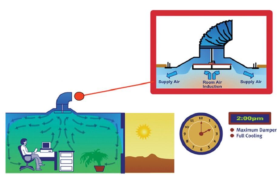
3 Disadvantages of Pressure Independent Systems Excessive fan power required to develop high duct pressures (Power absorbed is proportional to pressure) Associated with the above, are the higher noise levels requiring additional attenuation Lack of flexibility. It is difficult to split into two a zone served by a single VAV box and still maintain individual control in each sub-zone Because the terminal outlet has fixed opening size, there is a risk of cold air dumping and hot air stratification at reduced airflows. The aspect will be examined in more detail later Costs can be high in a situation that requires a large number of small offices to be served by individually controlled terminals Disadvantages of Pressure Independent Systems Duct sizes need to be larger to compensate for lower air velocities For optimum performance, it is important to pay close attention to the design and installation of the supply air duct system. A poorly designed duct system will compromise the equal pressure requirement for the outlets System can be more expensive in situations where a large number of outlets serve a common space or zone, such as an open plan office. It may be stated at this point that because the system is based upon the principal of constant duct static pressure, it is not necessary to monitor the air velocity at any point in the system. Supply air volume will always be proportional to damper opening Low Pressure Systems with Variable Geometry Outlets Essential Components The alternative to the above, also known as a pressure dependent system, consists of the following Cooling/Heating coils, filters etc, as above Supply air fan, also generally variable speed, capable of supplying duct pressures, at the fan discharge, in the region of 250Pa. An explanation of this will be given later Supply air ducting, designed for low pressures and velocities (below 10m/s) A means of duct static pressure control Variable volume outlets, which vary the supply air volume at the point of discharge into the occupied space A temperature controller that will control the supply air volume of a particular outlet (or group of outlets) in accordance with the cooling/heating demands for that space Advantages of Pressure Dependent Systems Lower fan power requirements for the lower duct pressures Lower fan sound power levels, associates with the above Flexibility. Each outlet can be individually controlled; A group of outlets operated by a single temperature controller may easily be split, merely by the addition of another controller (in the case of electronically controlled units) Because the duct static pressure is controlled and kept constant, it is possible to mix constant volume and variable volume diffusers on the same supply duct system No risk of cold air dumping or hot air stratification because of the variable geometry nature of the outlet. This feature will be more closely examined later Can be more cost effective for applications that require each outlet to be individually controlled. 3. COMPARISON OF TERMINAL OUTLETS The function of an air diffuser is to supply cold or warm air to an occupied space evenly, without causing excessive air movement at any particular point in the room while at the same time providing near-uniform temperatures throughout the occupied zone. To do this, it must introduce air above the occupied zone at a velocity high enough to mix well with room air, such that it slows down to a harmless speed before reaching the occupied zone. It takes energy to produce this mixing and this energy can only come from the velocity of the primary air stream itself. This mixing, otherwise known as entrainment or induction, is a function of discharge velocity and length of perimeter from which the air is discharged. So for example, a round nozzle will generate little induction when compared with a long slot type diffuser, for a given opening size and airflow rate. Therefore, to optimize the induction, the discharge velocity and exit perimeter length need to be maximized Fixed Aperture Outlets SUPPLY AIR DUCT In case of the conventional VAV box system, the airflow rate is controlled some distance upstream of the point of air discharge and the high escape velocities from the damper device cannot be used directly to generate room air entrainment or induction. This is because the associated outlets have a fixed aperture and their discharge velocity is proportional to volume. Using the energy formula for a moving body : Kinetic energy, E = ½ MV 2 VOLUME CONTROL UNIT Where: M = Mass & V = Velocity FLEXIBLE DUCT Figure 1: Fixed Aperture Outlet. FIXED APERTURE AIR OUTLET

4 In the case of the fixed aperture outlet, M and V change at the same rate as flow and therefore it can be seen that energy changes with the cube of the volume flow rate. The relationship between energy and volume flow rate through the normal range of volume control is shown in Table 1. Obviously at a flow rate of 33% there is very little energy left to generate the induction of secondary room air into the supply air stream. This drastically reduced energy leads to the dumping of cold air onto occupants below Variable Geometry Outlets In the case of variable geometry diffusers, the flow rate is controlled by changing the outlet area at the point of discharge. This has distinct advantages. The first is the regain of static pressure at the outlet under reduced air volume conditions, which may be explained using the square law principle. AT 33% AIRFLOW Static pressure at A Velocity at B = V2 Static pressure loss P2 at 33% airflow Using square law: = 60Pa = 1.75m/s P2 = P1 x (V 2 /V 1 ) 2 = 60 x (1.75/5.3) 2 = 1.7Pa (friction in flexible duct) Static pressure B = through aperture) = 58.3Pa (available to force air P 2 /P 1 = (V 2 /V 1 ) 2 Figure 2 shows a typical supply air duct, flexible duct connection and a variable geometry diffuser with motorized damper actuator. The static pressure in duct A remains constant at all times by virtue of the static pressure control system, which is examined in greater detail later. The volume control damper in the diffuser varies the discharge aperture in accordance with the demand of the room thermostat. As the flow rate diminishes; the static pressure loss due to friction in the flexible duct reduces in proportion to the square of the flow rate. So, at the minimum air condition, there is in fact more static pressure available at the discharge to increase the jet velocity, which in turn enhances the room air induction rate. This increase in available static pressure is depicted in Figure 3. Figure 3: Static Pressure at Outlet versus Volume Flow Rate If the energy equation is applied to variable geometry diffusers, it will be seen that as flow is reduced, only the mass of moving air is reduced. Discharge velocity is maintained and in fact is slightly increased because of the regain of static pressure as shown above. SUPPLY AIR DUCT This results in the following comparative energy relationship. Table 1: Comparative Energy for Variable Geometry Outlets VARIABLE GEOMETRY DIFFUSER COMPARATIVE ENERGY FLOW RATE FIXED APERTURE VARIABLE GEOMETRY 100% 100% 100% 75% 42% 76% INDUCED ROOM AIR Figure 2: Variable Geometry Outlet. 50% 12,5% 54% 33% 3,6% 40% AT MAXIMUM AIRFLOW Comparing these results leaves little doubt of the greater effectiveness of the variable geometry type of diffuser for VAV air distribution. Static pressure at A Velocity at B = V 1 Pressure loss due to friction = P 1 duct) Static pressure at B = through aperture) = 60Pa = 5.3m/s = 16Pa (friction in flexible = 44Pa (available to force air 4. DUCT DESIGN When designing a low pressure VAV system, which uses variable geometry diffusers, correct duct design is of the utmost importance for a successful installation. While good duct design is a relatively
5 simple task, it is probably the least understood aspect of a VAV installation. As stated previously, the conventional high-pressure system is very tolerant of duct design deficiencies because there is usually substantially more pressure available throughout the system than is actually required. It is precisely this type of over-design philosophy that creates problems if applied to low-pressure systems, results in high noise levels or excessive air at terminals under minimum air conditions. Duct sizing is usually accomplished by one of the following methods. 1. EQUAL FRICTION 2. STATIC REGAIN The equal friction method is the more common one and, as the name implies, results in a system in which the duct static pressure reduces at a constant rate down the length of the duct. So for example if a duct is 30m long and is designed for a friction rate of 0.1Pa/m, the static pressure at the end of the duct will be 30Pa lower than at the beginning. This is for a simple straight duct and with a few bends and fittings the static pressure loss could easily double to 60Pa. This method is fine for constant volume systems where manual duct dampers may be used to throttle the airflow to achieve a balanced system. All a throttling damper in fact does is destroy static pressure, which results in lower airflow rates. It is important to understand that a volume control damper is primarily a static pressure reducing device the airflow cannot be reduced unless the static pressure loss is increased. Volume flow rate through a diffuser is therefore directly related to static pressure in the duct. To get more air out of a diffuser, reduce the static pressure loss by opening the throttling damper. The equal friction method of duct sizing will work satisfactorily for low pressure systems with variable geometry diffusers only if the duct runs are short or if the duct velocities are kept low (below 5m/ s). If the duct run is short, the static pressure loss from beginning to end of the duct will not amount to much and if the velocities are kept low, the friction rate per metre of duct is very low (±.33Pa/m), resulting in small static pressure losses. For more complex systems, it is essential to use the static regain method of duct sizing. It is important to do the duct design correctly from the outset because there is no cure for a duct that has been undersized. A low pressure VAV system utilizing variable geometry diffusers relies on having the same constant static pressure at the take-off to each outlet. This being achieved by using the static regain method of duct sizing. This paper does not seek to explain how static regain duct sizing is done; for this purpose there are various software programs available from various sources. One objection to the use of this method to size ducting is that it results in larger and more expensive ducting. While this is true, the extent of the increase is often overestimated. The weight of sheet metal required for a system designed by static regain is approximately 13% more than the system designed by equal friction. However, the marginal increase in first cost, is essentially offset by the cost of reduced balancing time and operating costs. To put the size issue into perspective, the following illustrates the relationship between air volume and duct size. Volume is proportional to the square of the duct dimension i.e. to increase the volume of air carried in a duct by 50%, a typical duct size would have to DESIGN OF AN EFFECTIVE LOW PRESSURE VAV AIR DISTRIBUTION SYSTEM increase from 20x16 to 24x20. It is the area that increases by 50%, not the duct dimensions. Similarly, significant reductions in air velocity require only modest increases in duct size. The basic principle of the static regain method is to size a duct run so that the increase in static pressure at each take-off just offsets the loss due to friction in the succeeding section of duct. Static regain occurs when air slows down. A brief explanation of this is as follows: In a perfect system where friction is ignored, the Total pressure of the air remains constant as it travels through a diverging section of duct from A to B. A Figure 4: Air Travelling through a diverging duct. Now P total = P static + P velocity. As the velocity, and therefore velocity pressure, reduces from point A to point B, the static pressure must increase simultaneously to maintain total pressure constant. In reality, we have to contend with friction and this reduces the static regain by a factor, preventing a full recovery of pressure. In practice this means that the air velocity is systematically reduced from the first take-off or branch duct all the way to the last take-off. Generally a size reduction of less than 2 inches is regarded as being uneconomical and not essential. Towards the end of the duct run the duct size could become quite small and in this case a 1 inch reduction may be sufficient to justify its inclusion. The use of a duct smaller than 150mm x 200mm is not recommended. Under certain conditions, the static regain method produces some unexpected results although there is a perfectly logical explanation for these. For example, if the take-offs are far apart, the frictional pressure loss is relatively large and a duct size reduction may not be required the reduced flow rate after a take-off in the same size duct results in sufficient slowing down of the air to produce the required static regain. 5. FAN SELECTION One of the main advantages of the low pressure VAV air distribution system is the reduced fan power requirement. To make the most of this feature, it is important to have a clear understanding of how to calculate the total system pressure against which the fan must operate. Space does not allow a detailed analysis of every component, but the following guidelines will provide the engineer with the basic information needed to successfully predict the fan requirements Simple Systems A simple system is shown in Figure 5. Return air ducting may or may not be required, often depending on the size of the system and whether it is possible for the return air to find its way back to the air handling unit directly through corridors etc. However, there will be some pressure loss associated with the return air, even if only through a louver. B
6 D C B P velocity = 0.50r (V)2 Where; r = air density in kg/m³ V = velocity in m/s A Fan total pressure is simply the sum of static and velocity pressures. Note that the size of the header duct (A to B) is the same for both equal friction and static regain method of duct sizing. Based on the information given in Table 3, select a starting velocity appropriate to the particular system and calculate the pressure loss in this first section of duct. Ideal starting velocities are in the range 7 9m/s. Table 2: Recommended maximum duct velocities for low pres sure systems Figure 5: A Simple Air Distribution System. TABLE 2: RECOMMENDED MAXIMUM DUCT VELOCITIES FOR LOW VELOCITY SYSTEM (m/s) The fan will be required to overcome the resistance through the following elements: a) Return air ducting/louver etc. APPLICATION CONTROLLING FACTOR: NOISE GENERATION CONTROLLING FACTOR : DUCT FRICTION MAIN DUCTS BRANCH DUCTS B) Pressure losses inside the AHU, e.g. air filter, cooling/heating coil, entry & exit losses. c) Static pressure loss due to friction in the first section of duct from A to B. d) The static pressure in the remainder of the duct system. This is the pressure at which the diffusers are selected and is generally in the range ins. wg. The pressure losses inside the AHU may be obtained from the vendor. The pressure loss from A to B is obtained by calculation and depends on air velocity and equivalent duct length, which takes into account number of bends etc. RESIDENCES APARTMENTS HOTEL BEDROOMS HOSPITAL BEDOOMS PRIVATE OFFICES DIRECTORS ROOMS LIBRARIES THEATRES AUDITORIUMS GENERAL OFFICES HIGH CLASS STORES RESTAURANTS BANKS AVERAGE STORES CAFETERIAS INDUSTRIAL MAIN DUCTS SUPPLY RETURN SUPPLY RETURN From point B onwards, the fan sees only the static pressure required to overcome the friction through the flexible duct and the air outlet terminal, which is typically around 0.24 ins. wg. This can be summarized as follows, for a typical simple system: Inches wg (Static): a) Return air components 100 b) Air handling equipment 400 c) Duct friction (A-B) 40 d) System pressure Pa 5.2. Large Systems For a larger system where, for example, a single AHU serves a number of floors of a building, a slightly different approach is usually taken. This is done by dividing the air distribution system into the most conveniently selected low pressure supply duct zones, fed from medium pressure main ducts or risers, via branch duct dampers which control the static pressure in the branch ducts. R DAMPER S STATIC PRESURE SENSOR The fan selection is generally carried out on the basis of total pressure (Static plus velocity pressure). Based on the air volume and the size of the fan discharge, the velocity pressure at the fan discharge may be calculated as follows: S S BRANCH DUCT Figure 6. Larger, more complex air distribution system.
7 This layout reduces the size of the riser duct where space may be limited. The riser duct should also be sized using the static regain method, especially for high-rise buildings where the length of the duct is significant. For such riser ducts noise is often less of a determining factor and initial velocities of up to 10m/s may be used quite safely. If the static pressure in the low pressure branch duct is in the region of 40 to 70Pa, then the static pressure just upstream of the pressure controlling branch duct damper need be no more than 100 to 200Pa above pressure. This would normally eliminate the need for sound attenuators after the Pressure Control Damper. Both riser duct and branch duct static pressure are controlled from static pressure sensors, positioned at a point about one half to two thirds of the distance between the duct damper or supply air fan and the end of the duct section. 6. BYPASS DAMPERS Bypass dampers may also be used effectively for the control of duct static pressure, especially in smaller systems where fan power is not significant. In this case, fan power saving is not possible as the volume of air through the fan is not reduced as the diffusers close down. DESIGN OF AN EFFECTIVE LOW PRESSURE VAV AIR DISTRIBUTION SYSTEM 7. BALANCING THE AIR DISTRIBUTION SYSTEM A well designed duct system, which has been sized using the static regain method, is essentially self balancing. No attempt must be made to balance the airflow by means of manually operated dampers placed in the duct spin-in collars. There is a very good reason for this. Manual dampers add series resistance to the flow and this resistance changes as the square of the flow. Therefore at full flow (100%) the manual damper will offer a high resistance (say 45Pa, for example), whereas at 33% flow, the resistance will reduce to (33/100) ² or 1/9th of 45Pa i.e. 5Pa. This means that at full flow the damper will reduce the static pressure to the diffuser by 45Pa. Whereas, at minimum flow the static pressure at the diffuser will rise by 40Pa thereby resulting in unacceptably high noise levels and possible space over-cooling. If is far better to put the extra effort into correct duct design and effect cost savings in terms of both hardware and labor, not to mention the benefit of a system which operates at low noise level and efficiently. Note that flexible ducts that are excessive in length or excessively looped have the same effect as a manual damper. 6.1 Sizing of Bypass Damper It must be borne in mind - if the outlet diffusers are able to turn down to 33% of maximum, then the bypass damper must be sized to handle 67% of the total supply air quantity. It is recommended that the bypass damper be sized for an average face velocity of between 800 & 1000 fpm. At higher face velocities the pressure drop across the fully open damper will increase and insufficient air will pass through the damper, causing the static pressure in the duct to rise above the required level. If the size of the bypass damper is restricted or limited as a result of restricted available space, it may be necessary to include a face damper to operate in conjunction with the bypass damper. This is shown in Figure COMMISSIONING The discussion here is restricted to the commissioning of the static pressure control system and variable geometry diffusers. It also assumes that the system has been checked for obvious faults such as ruptured or disconnected flexible ducting, air leaks, etc. Avoid commissioning a system when warm air is being supplied by the air handling unit, especially when the balancing hood method is used to measure air volumes. The stack effect created by the warm air in the hood will artificially reduce volume flow through a diffuser Simple System A simple system would consist of a single AHU with variable speed fan serving a single run of duct with a number of variable geometry diffusers. BYPASS DAMPER FACE DAMPER (OPTIONAL) I G E C A AHU AHU J H F D B Figure 7: Face & Bypass Dampers. Figure 8: Commissioning a Simple System. 6.2 Type of Pressure Control Damper The modulating damper used for pressure control should be of the type which has airfoil shaped vanes. This type has a near-linear air transfer characteristics, unlike opposed blade or parallel blade type dampers, which have non-linear characteristics. The airfoil blade type provides much more stable control, especially at minimum air volumes. The first step would be to drive all the diffusers to the fully open position. If the system has been designed for a specific volume diversification factor, open only enough of the VAV diffusers to allow the maximum simultaneous air volume for which the system has been designed, to flow through the duct. Now select the diffuser requiring the highest pressure to satisfy its design volume (in this system probably I or J furthest from the AHU) and measure the supply air volume from this diffuser using a correctly sized balancing hood. Adjust the static pressure in the duct until the desired air volume for this diffuser has been achieved.
8 Once this diffuser is satisfied, it is safe to assume that all diffusers further upstream will deliver no less than the design air quantity. A few random spot checks should confirm this. In operation the system becomes self-balancing as each diffuser adjusts to the required room load Larger, More Complex Systems Larger systems would generally consist of an AHU which supplies air to a high pressure header duct, which in turn serves a number of branch ducts. Each branch duct would have an independent pressure control damper to control the static pressure in that duct, throughout the range of airflow volumes. EAST ZONE INTERNAL ZONE WEST ZONE The first type of application favors the VAV box system, as a large number of low cost, fixed aperture outlets may be connected to a single volume control VAV box. However, where all or most of the outlets are required to have their own temperature controller for individual comfort, the variable geometry diffuser system becomes more cost effective. As can be expected, there is a point between these two extremes at which the costs break even and the choice would depend on other factors such as flexibility and running costs. Appendix 1 shows the results of a study undertaken recently by a contracting company in Philadelphia USA. It was found that the break-even point occurred when the system required an average of about 6 outlets per VAV box. Above this the VAV box system is likely to be more cost effective while at 5 outlets or less (on average) the low pressure system with variable geometry outlets is more economical. It must be stressed that this may be used only as a guide although similar investigations in Malaysia, Israel and Australia have confirmed this finding. AIR HANDLING UNIT MAIN DUCT STATIC PRESSURE CONTROL BRANCH DUCT STATIC PRESSURE SENSOR PRESSURE CONTROL DAMPER Figure 9: Commissioning a Larger, more Complex System. The aim is to set the system up in such a way that the supply air fan static pressure is sufficient to supply the design air quantity to the diffuser furthest from the AHU, under the most demanding condition, i.e. when all diffusers served by the AHU are fully open. If a diversification factor has been used, it must be applied as stated earlier. The first task is to select the index branch duct. This is usually the branch duct furthest from the AHU, or the duct most likely to be starved if the fan does not supply sufficient air. The damper serving this duct must be driven to the fully open position. Next, fully open all the diffusers on this branch duct (presumably all these diffusers will be serving a common zone and there will be no diversity factor), and select the diffuser requiring the highest pressure to satisfy its design volume. Now adjust the static pressure in the header/main riser duct to the point where the selected diffuser meets the design airflow requirement. Finally, without changing anything in the branch duct, adjust the branch duct static pressure controller so that the pressure in that branch will be controlled at the level that exists when these measurements are made. With the header/main duct static pressure now set, each of the branch duct static pressure controllers may be adjusted using the procedure suggested for a simple system. At this stage the system is fully commissioned. However, the system may be tested by monitoring duct pressures, while changing airflow rates at various points in the system. In a system operating satisfactorily one would expect duct pressures to vary by less than 10% as airflows vary from 100% down to 30%. The study also revealed, predictably, that the annual operating costs were some 37% lower for the low-pressure system than for the VAV box system. 10. CONCLUSION Although there is much more that may be said about air distribution, from the information presented in this paper the air conditioning engineer should have a clear understanding of the basic principles involved in the process of VAV air distribution. It should also be clear that a low pressure, pressure dependent system using variable geometry diffusers offers one of the most effective ways to provide excellent room conditions for human comfort. This system also meets the challenge of providing state-of-the-art technology at affordable cost, without compromising individual comfort or indoor air quality. By paying close attention to the potential pitfalls highlighted in this paper, the engineer can be confident of being able to design and install an effective air distribution system. 11. ACKNOWLEDGEMENT The author wishes to thank the Directors of Rickard Air Diffusion (Pty) Ltd for permission to publish this paper as well as for making available the time and information resources without which this paper would not have been possible. 12. BIBLIOGRAPHY 1. Chen, S.Y.S. and Demster, S.J: Variable Air Volume Systems for Environmental Quality. McGraw Hill Book Company (1996) 9. COST COMPARISONS There is no simple cost comparison that can be made between a conventional VAV box system and a low-pressure system using variable geometry diffusers. This is because the cost depends on whether the system is designed to serve relatively large zones where a large number of outlets may be operated by single temperature controller, or whether the building has many small offices, each requiring an individually controlled outlet. 2. ASHRAE: ASHRAE Handbook 1997 Fundamentals, American Society of Heating, Refrigeration and Air Conditioning Engineers, Inc., Chapter 31 & 32 (1997) 3. Carrier Air Conditioning Company: Handbook of Air Conditioning Design, Part 2. McGraw Hill Book Company (1965)
9 APPENDIX Fan Powered VAV Boxes: 1.1 External zones - 17 x VAV Boxes cooling/heating $ 13, Internal zones - 8 x VAV Boxes cooling only $ 4, VAV box installation $ 1, Supply air diffusers and balancing dampers $ 4, System Balancing $ 2, Air Handling Unit $ 30, Analog controls Included 1.8 Hot water coil valves $ 1, Hot water piping supply and installation $ 8, Electrical wiring to VAV boxes and controls $ 5,125 Total cost: $ 71,400 Annual operating costs assuming 75% AHU motor efficiency and 50% fan powered VAV box motor efficiency $ 12, Standard VAV Boxes: 2.1 External zones - 17 x VAV Boxes cooling/heat $ 7, Internal zones - 8 x VAV Boxes cooling only $ 2, VAV box installation $ 1, Supply air diffusers and balancing dampers $ 4, System Balancing $ 2, Air Handling Unit $ 30, Analog controls Included 2.8 Hot water coil valves $ 1, Hot water piping supply and installation $ 8, Electrical wiring to VAV boxes and controls $ 3,125 Total cost: $ 61,050 Annual operating costs assuming 75% AHU motor efficiency $ 7,603
10 3. Thermally Powered Variable Geometry VAV Diffusers: 3.1 External zones-68 x VSD 7-4 S24 heat/cool diffusers $ 11, Internal zones-32 x VSD 7-4 S24 cool only diffusers $ 4, Two Pressure control dampers and controls $ 1, Four hot water duct heating coils $ 1, Four hot water heating coil valves $ Hot water piping supply and installation $ 4, VAV diffuser balancing $ Air Handling Unit $ 30, Damper electrical wiring $ 350 Total cost: $ 53,970 Annual operating costs assuming 75% AHU motor efficiency $ 4, Electronically Controlled Variable Geometry VAV Diffusers: 4.1 Ext. zones-17 x VSD 7-1 S24 heat/cool master diffusers $ 4, Int. zones-8 x VSD 7-1 S24 cool only master diffusers $ 2, x VSD 7-1 S24 slave diffusers $ 12, Two Pressure control dampers and controls $ 1, Four hot water duct heating coils $ 1, Four hot water heating coil valves $ Hot water piping supply and installation $ 4, VAV diffuser balancing $ Air Handling Unit $ 30, Damper electrical wiring $ 3,125 Total cost: $ 59,870 Annual operating costs assuming 75% AHU motor efficiency $ 4,752
CLB 3 ATTRACTIVE JOINABLE LINEAR PROFILE EASILY ACCESIBLE VOLUME ADJUSTMENT INCLUDED FLEX CLAMP HEATING AND COOLING TERMINAL REHEAT AVAILABLE
 CONSTANT VOLUME LINEAR BAR CEILING DIFFUSER CLB 3 ATTRACTIVE JOINABLE LINEAR PROFILE EASILY ACCESIBLE VOLUME ADJUSTMENT INCLUDED FLEX CLAMP HEATING AND COOLING TERMINAL REHEAT AVAILABLE CONTROL THE PERIMETER
HAP e-help. Obtaining Consistent Results Using HAP and the ASHRAE 62MZ Ventilation Rate Procedure Spreadsheet. Introduction
 Introduction A key task in commercial building HVAC design is determining outdoor ventilation airflow rates. In most jurisdictions in the United States, ventilation airflow rates must comply with local
acculink platinum zv zoning system
 acculink platinum zv zoning system Components: AZONE950AC52ZA ZZONEPNLAC52ZA AZONE940 ZZONEEZPAC52ZB Platinum 950 Control Zone Panel Kit up to 4 zones Included: Discharge Air Temp sensor Static Pressure
FLOW CONSIDERATIONS IN INDUSTRIAL SILENCER DESIGN
 FLOW CONSIDERATIONS IN INDUSTRIAL SILENCER DESIGN George Feng, Kinetics Noise Control, Inc., 3570 Nashua Drive, Mississauga, Ontario Vadim Akishin, Kinetics Noise Control, Inc., 3570 Nashua Drive, Mississauga,
APPLYING VARIABLE SPEED PRESSURE LIMITING CONTROL DRIVER FIRE PUMPS. SEC Project No
 APPLYING VARIABLE SPEED PRESSURE LIMITING CONTROL DRIVER FIRE PUMPS SEC Project No. 1803007-000 November 20, 2006 TABLE OF CONTENTS I. ABSTRACT...1 II. INTRODUCTION...1 III. HISTORY...2 IV. VARIABLE SPEED
Application Block Library Fan Control Optimization
 Application Block Library Fan Control Optimization About This Document This document gives general description and guidelines for wide range fan operation optimisation. Optimisation of the fan operation
REQUIREMENTS AND HAND-OVER DOCUMENTATION FOR ENERGY-OPTIMAL DEMAND-CONTROLLED VENTILATION
 REQUIREMENTS AND HAND-OVER DOCUMENTATION FOR ENERGY-OPTIMAL DEMAND-CONTROLLED VENTILATION Mads Mysen* 1, Axel Cablé 1, Peter G. Schild 1, and Kari Thunshelle 1 1 SINTEF Building and Infrastructure Forskningsveien
THE IMPORTANCE OF SUCTION LINES
 THE IMPORTANCE OF SUCTION LINES Analysis and connection to compressors Unicla Cat. No. B1801 Copyright 2018 All rights reserved No part of this document shall be reproduced in whole or in part without
Use of Correction Factors When Commissioning Air Systems
 Shaun Matthews G5 Thesis 24 th January 2016 Rev. 2 Use of Correction Factors When Commissioning Air Systems S. Matthews Grade 5 Thesis - Use Of Correction Factors Rev. 2 1 of 12 Contents Introduction What
Hydronic Systems Balance
 Hydronic Systems Balance Balancing Is Misunderstood Balancing is application of fundamental hydronic system math Balance Adjustment of friction loss location Adjustment of pump to requirements By definition:
The Advancement of Pressure Independent Technology
 The Advancement of Pressure Independent Technology This session will look at the new pressure independent technology and its energy savings potential. Topics include: A brief review of the differences
Control of Nuclear Gloveboxes and Enclosures Using the No- Moving-Part Vortex Amplifier (VXA)
") Control of Nuclear Gloveboxes and Enclosures Using the No- Moving-Part Vortex Amplifier (VXA) ABSTRACT M.J. Crossley AEA Technology ES. Inc. 1100 Jadwin Ave, Richland, WA 99352, USA This paper describes
Control of Nuclear Gloveboxes and Enclosures Using the No- Moving-Part Vortex Amplifier (VXA) ABSTRACT M.J. Crossley AEA Technology ES. Inc. 1100 Jadwin Ave, Richland, WA 99352, USA This paper describes
OIL AND GAS INDUSTRY
 This case study discusses the sizing of a coalescer filter and demonstrates its fouling life cycle analysis using a Flownex model which implements two new pressure loss components: - A rated pressure loss
Outside Air Nonresidential HVAC Stakeholder Meeting #2 California Statewide Utility Codes and Standards Program
 1 Outside Air Nonresidential HVAC Stakeholder Meeting #2 California Statewide Utility Codes and Standards Program Jim Meacham, CTG Energetics Agenda 2 In Situ Testing Results Reduced Ventilation after
Acoustical Modeling of Reciprocating Compressors With Stepless Valve Unloaders
 Acoustical Modeling of Reciprocating Compressors With Stepless Valve Unloaders Kelly Eberle, P.Eng. Principal Engineer keberle@betamachinery.com Brian C. Howes, M.Sc., P.Eng. Chief Engineer bhowes@betamachinery.com
Best Practices Pneumatics Machine & Design. Written by Richard F. Bullers, CFPPS as published in Fluid Power Journal, July/August 2016
 Pneumatics Machine & Design Written by Richard F. Bullers, CFPPS as published in Fluid Power Journal, July/August 2016 Contents at Atmospheric Air The air at a compressor s intake contains about 78% nitrogen,
Every things under control High-Integrity Pressure Protection System (HIPPS)
") Every things under control www.adico.co info@adico.co Table Of Contents 1. Introduction... 2 2. Standards... 3 3. HIPPS vs Emergency Shut Down... 4 4. Safety Requirement Specification... 4 5. Device Integrity
Every things under control www.adico.co info@adico.co Table Of Contents 1. Introduction... 2 2. Standards... 3 3. HIPPS vs Emergency Shut Down... 4 4. Safety Requirement Specification... 4 5. Device Integrity
International Journal of Technical Research and Applications e-issn: , Volume 4, Issue 3 (May-June, 2016), PP.
, PP.") DESIGN AND ANALYSIS OF FEED CHECK VALVE AS CONTROL VALVE USING CFD SOFTWARE R.Nikhil M.Tech Student Industrial & Production Engineering National Institute of Engineering Mysuru, Karnataka, India -570008
DESIGN AND ANALYSIS OF FEED CHECK VALVE AS CONTROL VALVE USING CFD SOFTWARE R.Nikhil M.Tech Student Industrial & Production Engineering National Institute of Engineering Mysuru, Karnataka, India -570008
Technical vs. Process Commissioning Final Exam: Functional Performance Testing
 ASHRAE www.ashrae.org. Used with permission from ASHRAE Journal, June 2014 at www.atkinsglobal.com. This article may not be copied nor distributed in either paper or digital form without ASHRAE s permission.
PLEA th Conference, Opportunities, Limits & Needs Towards an environmentally responsible architecture Lima, Perú 7-9 November 2012
 Natural Ventilation using Ventilation shafts Multiple Interconnected Openings in a Ventilation Shaft Reduce the Overall Height of the Shaft While Maintaining the Effectiveness of Natural Ventilation ABHAY
The Use of a Process Simulator to Model Aeration Control Valve Position and System Pressure
 The Use of a Process Simulator to Model Aeration Control Valve Position and System Pressure Matthew Gray 1 * and Steve Kestel 1 1 BioChem Technology, King of Prussia, PA *Email: mgray@biochemtech.com ABSTRACT
Another convenient term is gauge pressure, which is a pressure measured above barometric pressure.
 VACUUM Theory and Applications Vacuum may be defined as the complete emptiness of a given volume. It is impossible to obtain a perfect vacuum, but it is possible to obtain a level of vacuum, defined as
FloCon Commissioning Modules DESIGN GUIDE - JUNE Variable Flow Systems & Solutions brought to you by Hurlstones
 DESIGN GUIDE - JUNE 2008 Variable Flow Systems & FloCon Commissioning Modules Patent No. GB2 376 066B www.savmodules.com Solutions brought to you by Hurlstones CONTENTS Page 1. INTRODUCTION 3 2. BENEFITS
AN INVESTIGATION OF LONGITUDINAL VENTILATION FOR SHORT ROAD TUNNELS WITH HIGH FIRE HRR
 - 9 - AN INVESTIGATION OF LONGITUDINAL VENTILATION FOR SHORT ROAD TUNNELS WITH HIGH FIRE HRR O Gorman S., Nuttall R., Purchase A. Parsons Brinckerhoff, Australia ABSTRACT Recent fire tests for tunnels
VAV SYSTEM INDOOR AIR QUALITY CONSIDERATIONS FOR OFFICE SPACES
 Proceedings: Indoor Air 005 A SYSTEM INDOOR AIR QUALITY CONSIDERATIONS FOR OFFICE SPACES PH Zhang * Jacobs Civil, Inc. 60 Madison Avenue, 1 th Floor, NYC, NY10016, USA ABSTRACT This paper discusses indoor
INTERPRETATION IC OF ANSI/ASHRAE STANDARD VENTILATION FOR ACCEPTABLE INDOOR AIR QUALITY
 INTERPRETATION IC 62-2001-06 OF ANSI/ASHRAE STANDARD 62-2001 VENTILATION FOR ACCEPTABLE INDOOR AIR QUALITY REVISION APPROVED: 1/12/2002 Originally issued as interpretation of Standard 62-1989 (IC 62-1989-23)
Measuring range Δp (span = 100%) Pa
 Pa") 4.4/ RLE 5: Volume-flow controller, continuous How energy efficiency is improved Enables demand-led volume flow control for the optimisation of energy consumption in ventilation systems. Areas of application
4.4/ RLE 5: Volume-flow controller, continuous How energy efficiency is improved Enables demand-led volume flow control for the optimisation of energy consumption in ventilation systems. Areas of application
COMPARISON OF DIFFERENTIAL PRESSURE SENSING TECHNOLOGIES IN HOSPITAL ISOLATION ROOMS AND OTHER CRITICAL ENVIRONMENT APPLICATIONS
 COMPARISON OF DIFFERENTIAL PRESSURE SENSING TECHNOLOGIES IN HOSPITAL ISOLATION ROOMS AND OTHER CRITICAL ENVIRONMENT APPLICATIONS APPLICATION NOTE LC-136 Introduction Specialized spaces often times must
INSTALLATION & OPERATION MANUAL. Dual Duct VAV Terminals. Redefine your comfort zone.
 INSTALLATION & OPERATION MANUAL Dual Duct VAV Terminals IOM Dual Duct VAV Terminals IMPORTANT! READ BEFORE PROCEEDING! GENERAL SAFETY GUIDELINES This equipment is a relatively complicated apparatus. During
AUTOMATIC FLOW CARTRIDGES. Competition Analysis Not All Automatics Are Created Equal
 - AUTOMATIC FLOW CARTRIDGES Competition Analysis Not All Automatics Are Created Equal IMI FLOW DESIGN / AUTOMATIC FLOW CARTRIDGES / F345.0 COMPETITION ANALYSIS Improve the of your Premium System Components...
Practical Guide. By Steven T. Taylor, P.E., Member ASHRAE
 ractical Guide The following article was published in ASHRAE Journal, March 2003. Copyright 2003 American Society of Heating, Refrigerating and Air- Conditioning Engineers, Inc. It is presented for educational
Sizing of extraction ventilation system and air leakage calculations for SR99 tunnel fire scenarios
 Sizing of extraction ventilation system and air leakage calculations for SR99 tunnel fire scenarios Yunlong (Jason) Liu, PhD, PE HNTB Corporation Sean Cassady, FPE HNTB Corporation Abstract Extraction
PIG MOTION AND DYNAMICS IN COMPLEX GAS NETWORKS. Dr Aidan O Donoghue, Pipeline Research Limited, Glasgow
 PIG MOTION AND DYNAMICS IN COMPLEX GAS NETWORKS Dr Aidan O Donoghue, Pipeline Research Limited, Glasgow A model to examine pigging and inspection of gas networks with multiple pipelines, connections and
Excellent Duct Systems Require Design, Not Guesswork!
 Design Advisory #2: CAS-DA2-2003 Excellent Duct Systems Require Design, Not Guesswork! Duct System Design Guide: Chapter 2 HVAC system performance is only as good as it s weakest link. Unfortunately, duct
HVAC Air Duct Leakage. Tech University 2013 Presented By: Mark Terzigni Project Manager Technical Services SMACNA
 HVAC Air Duct Leakage Tech University 2013 Presented By: Mark Terzigni Project Manager Technical Services SMACNA Learning Objectives Understand the difference between System leakage and Duct leakage Understand
Drilling Efficiency Utilizing Coriolis Flow Technology
 Session 12: Drilling Efficiency Utilizing Coriolis Flow Technology Clement Cabanayan Emerson Process Management Abstract Continuous, accurate and reliable measurement of drilling fluid volumes and densities
INDIAN INSTITUTE OF TECHNOLOGY KHARAGPUR NPTEL ONLINE CERTIFICATION COURSE. On Industrial Automation and Control
 INDIAN INSTITUTE OF TECHNOLOGY KHARAGPUR NPTEL ONLINE CERTIFICATION COURSE On Industrial Automation and Control By Prof. S. Mukhopadhyay Department of Electrical Engineering IIT Kharagpur Topic Lecture
2005 CERTIFICATE OF ACCEPTANCE (Part 1 of 3) MECH-1-A
 MECH-1-A") 2005 CERTIFICATE OF ACCEPTANCE (Part 1 of 3) MECH-1-A PROJECT ADDRESS TESTING AUTHORITY TELEPHONE Checked by/date Enforcement Agency Use GENERAL INFORMATION OF BLDG. PERMIT PERMIT # BLDG. CONDITIONED FLOOR
2005 CERTIFICATE OF ACCEPTANCE (Part 1 of 3) MECH-1-A PROJECT ADDRESS TESTING AUTHORITY TELEPHONE Checked by/date Enforcement Agency Use GENERAL INFORMATION OF BLDG. PERMIT PERMIT # BLDG. CONDITIONED FLOOR
BLOCKAGE LOCATION THE PULSE METHOD
 BLOCKAGE LOCATION THE PULSE METHOD Presented by John Pitchford Pitchford In-Line Author James Pitchford ABSTRACT Pipeline blockages can result from a number of different mechanisms: wax or solid hydrates
Gerald D. Anderson. Education Technical Specialist
 Gerald D. Anderson Education Technical Specialist The factors which influence selection of equipment for a liquid level control loop interact significantly. Analyses of these factors and their interactions
OIL SUPPLY SYSTEMS ABOVE 45kW OUTPUT 4.1 Oil Supply
 OIL SUPPLY SYSTEMS ABOVE 45kW OUTPUT 4.1 Oil Supply 4.1.1 General The primary function of a system for handling fuel oil is to transfer oil from the storage tank to the oil burner at specified conditions
THE WAY THE VENTURI AND ORIFICES WORK
 Manual M000 rev0 03/00 THE WAY THE VENTURI AND ORIFICES WORK CHAPTER All industrial combustion systems are made up of 3 main parts: ) The mixer which mixes fuel gas with combustion air in the correct ratio
INTERACTION BETWEEN WIND-DRIVEN AND BUOYANCY-DRIVEN NATURAL VENTILATION Bo Wang, Foster and Partners, London, UK
 INTERACTION BETWEEN WIND-DRIVEN AND BUOYANCY-DRIVEN NATURAL VENTILATION Bo Wang, Foster and Partners, London, UK ABSTRACT Ventilation stacks are becoming increasingly common in the design of naturally
Understanding Centrifugal Compressor Capacity Controls:
 Understanding Centrifugal Compressor Capacity Controls: Richard Stasyshan, CAGI Technical Consultant and the Centrifugal Compressor Section of the Compressed Air & Gas Institiute (CAGI). CAGI and our centrifugal
New Energy-saving Air Compressors
 FEATURED ARTICLES Environmentally Conscious Technology in Industrial Fields Aiming for a Low-carbon Society New Energy-saving Air Compressors Air compressors produce compressed air and have a wide variety
Fail Operational Controls for an Independent Metering Valve
 Group 14 - System Intergration and Safety Paper 14-3 465 Fail Operational Controls for an Independent Metering Valve Michael Rannow Eaton Corporation, 7945 Wallace Rd., Eden Prairie, MN, 55347, email:
VENTILATION EFFICIENCIES OF A DESK-EDGE-MOUNTED TASK VENTILATION SYSTEM
 VENTILATION EFFICIENCIES OF A DESK-EDGE-MOUNTED TASK VENTILATION SYSTEM D Faulkner *, WJ Fisk, DP Sullivan and SM Lee Indoor Environment Dept., Lawrence Berkeley National Lab, Berkeley, CA, USA ABSTRACT
Experiment Instructions. Circulating Pumps Training Panel
 Experiment Instructions Circulating Pumps Training Panel Experiment Instructions This manual must be kept by the unit. Before operating the unit: - Read this manual. - All participants must be instructed
Process Simulator Evaluates Blower and Valve Control Strategies for WWTP Aeration
 Process Simulator Evaluates Blower and Valve Control Strategies for WWTP Aeration inshare By Steve Kestel and Tilo Stahl (BioChem Technology) and Matthew Gray (Keystone Engineering Group) Introduction
MANAGEMENT PROCEDURE FOR LABORATORY VENTILATION
 UNIVERSITY OF ALASKA FAIRBANKS SAFETY SYSTEM POLICY AND PROCEDURE DOCUMENT NUMBER: 508 ISSUE DATE: SEPTEMBER 1996 SUBJECT: Management Procedure for Laboratory Ventilation MANAGEMENT PROCEDURE FOR LABORATORY
The Discussion of this exercise covers the following points:
 Exercise 3-2 Orifice Plates EXERCISE OBJECTIVE In this exercise, you will study how differential pressure flowmeters operate. You will describe the relationship between the flow rate and the pressure drop
CALMO
 ---------------------------------------------------- Sound attenuator with recessed connection for rectangular ducts ---------------------------------------------------------------------- GENERAL is, due
INSTRUCTOR GUIDE REFERENCES: PUMPING APPARATUS DRIVER/OPERATOR HANDBOOK, FIRST EDITION, IFSTA
 TOPIC: RELAY PUMPING OPERATIONS LEVEL OF INSTRUCTION: TIME REQUIRED: ONE HOUR INSTRUCTOR GUIDE MATERIALS: APPROPRIATE AUDIO VISUAL SUPPORT REFERENCES: PUMPING APPARATUS DRIVER/OPERATOR HANDBOOK, FIRST
HCD HIGH CAPACITY DRUM LOUVER
 HIGH CAPACITY DRUM LOUVER The s (HCD) consist of extruded aluminum blades mounted inside a rotatable drum to produce long air throws with a high degree of directional control. Rotateable drum provides
Barcol-Air BRM Radiant Module
 Barcol-Air BRM Radiant Module General The high capacity Radiant Cooling Module BRM is based on the principles of the radiant cooling technology. Due to the purpose designed profile and the geometry of
Spring Loaded Regulators Constant Loaded Regulators Twin Parallel Flow Regulators Field Service Regulators
 Product Line Brochure J0B Effective Date 2/01 Spring Loaded Regulators Constant Loaded Regulators Twin Parallel Flow Regulators Field Service Regulators P R O D U C T L I N E O V E R V I E W Regulator
Transient Analyses In Relief Systems
 Transient Analyses In Relief Systems Dirk Deboer, Brady Haneman and Quoc-Khanh Tran Kaiser Engineers Pty Ltd ABSTRACT Analyses of pressure relief systems are concerned with transient process disturbances
Experiment 8: Minor Losses
 Experiment 8: Minor Losses Purpose: To determine the loss factors for flow through a range of pipe fittings including bends, a contraction, an enlargement and a gate-valve. Introduction: Energy losses
TExT Thorough Examination & Test of LEV Local Exhaust Ventilation Systems
 ILEVE -Institute of LEV Engineers CPD & Information Day TExT Thorough Examination & Test of LEV Local Exhaust Ventilation Systems Jane Bastow CMIOSH Chartered Safety and Health Practitioner OSCHR Registered
LindabSolus. Supply air beam. lindab we simplify construction
 lindab we simplify construction Lindab 03.2016 Lindab Ventilation. All forms of reproduction without written permission are forbidden. is the registered trademark of Lindab AB. Lindab's products, systems,
Experimental Analysis on Vortex Tube Refrigerator Using Different Conical Valve Angles
 International Journal of Engineering Research and Development e-issn: 7-067X, p-issn: 7-00X, www.ijerd.com Volume 3, Issue 4 (August ), PP. 33-39 Experimental Analysis on Vortex Tube Refrigerator Using
Efficiency Improvement of Rotary Compressor by Improving the Discharge path through Simulation
 Purdue University Purdue e-pubs International Compressor Engineering Conference School of Mechanical Engineering 2014 Efficiency Improvement of Rotary Compressor by Improving the Discharge path through
ESCONDIDO FIRE DEPT TRAINING MANUAL Section DRIVER OPERATOR Page 1 of 14 Hydraulics Revised
 DRIVER OPERATOR Page 1 of 14 HYDRAULICS Hydraulics applied in the dynamic fire ground environment is an art that comes with study and experience. The following describes the factors that must be mastered
Investigation on Divergent Exit Curvature Effect on Nozzle Pressure Ratio of Supersonic Convergent Divergent Nozzle
 RESEARCH ARTICLE OPEN ACCESS Investigation on Divergent Exit Curvature Effect on Nozzle Pressure Ratio of Supersonic Convergent Divergent Nozzle Shyamshankar.M.B*, Sankar.V** *(Department of Aeronautical
Exercise 2-3. Flow Rate and Velocity EXERCISE OBJECTIVE C C C
 Exercise 2-3 EXERCISE OBJECTIVE C C C To describe the operation of a flow control valve; To establish the relationship between flow rate and velocity; To operate meter-in, meter-out, and bypass flow control
SECTION TESTING ADJUSTING AND BALANCING FOR HVAC
 SECTION 23 05 93 - TESTING ADJUSTING AND [Note to PSC: Existing System Coordination When connecting to an existing system, it is the PSC s Responsibility to examine existing documents, field verify existing
OPTIMIZING THE LENGTH OF AIR SUPPLY DUCT IN CROSS CONNECTIONS OF GOTTHARD BASE TUNNEL. Rehan Yousaf 1, Oliver Scherer 1
 OPTIMIZING THE LENGTH OF AIR SUPPLY DUCT IN CROSS CONNECTIONS OF GOTTHARD BASE TUNNEL Rehan Yousaf 1, Oliver Scherer 1 1 Pöyry Infra Ltd, Zürich, Switzerland ABSTRACT Gotthard Base Tunnel with its 57 km
CSC-2000 SERIES. Reset Volume Controllers MADE IN U.S.A. DESCRIPTION MODELS SPECIFICATIONS ORDERING
 CSC-2000 SERIES Reset Volume Controllers MADE IN U.S.A. DESCRIPTION The CSC-2000 series are designed for use on VAV terminal units in HVAC systems. These are submaster air velocity controllers whose velocity
(Refer Slide Time: 2:16)
") Fluid Machines. Professor Sankar Kumar Som. Department Of Mechanical Engineering. Indian Institute Of Technology Kharagpur. Lecture-23. Diffuser and Cavitation. Good morning and welcome you all to this
Fluid Machines. Professor Sankar Kumar Som. Department Of Mechanical Engineering. Indian Institute Of Technology Kharagpur. Lecture-23. Diffuser and Cavitation. Good morning and welcome you all to this
SIZING AND CAPACITIES OF GAS PIPING
 APPENDIX A (IFGS) SIZING AND CAPACITIES OF GAS PIPING (This appendix is adopted as part of the code.) A.1 General. To determine the size of piping used in a gas piping system, the following factors must
Introduction to Pumps
 Introduction to Pumps 1 Introduction to Pumps 1.0 INTRODUCTION There are many different types of pump now available for use in pumped fluid systems. A knowledge of these pump types and their performance
Development of High-speed Gas Dissolution Device
 Development of High-speed Gas Dissolution Device Yoichi Nakano*, Atsushi Suehiro**, Tetsuhiko Fujisato***, Jun Ma**** Kesayoshi Hadano****, Masayuki Fukagawa***** *Ube National College of Technology, Tokiwadai
Chapter 5 5. INTERSECTIONS 5.1. INTRODUCTION
 Chapter 5 5. INTERSECTIONS 5.1. INTRODUCTION Intersections are the physical component of the roadways where two highways intersect. They are the most complex element of roadways, since it requires more
Pipeline Flooding, Dewatering and Venting Dr Aidan O'Donoghue, Pipeline Research Limited, Glasgow, Scotland
 Pipeline Flooding, Dewatering and Venting Dr Aidan O'Donoghue, Pipeline Research Limited, Glasgow, Scotland Abstract Flooding, cleaning, gauging, dewatering and venting of offshore oil and gas pipelines
High Efficiency SO2 Scrubber Design to Reduce Caustic Consumption
 High Efficiency SO2 Scrubber Design to Reduce Caustic Consumption Paper # 35 Andrew C. Bartocci Envitech, Inc. 2924 Emerson Street- Suite 320 San Diego, CA 92106 Ph: 619-223-9925, ext. 203 ABSTRACT An
ROUNDABOUT CAPACITY: THE UK EMPIRICAL METHODOLOGY
 ROUNDABOUT CAPACITY: THE UK EMPIRICAL METHODOLOGY 1 Introduction Roundabouts have been used as an effective means of traffic control for many years. This article is intended to outline the substantial
Single- or Two-Stage Compression
 The following article was published in ASHRAE Journal, August 2008. Copyright 2008 American Society of Heating, Refrigerating and Air- Conditioning Engineers, Inc. It is presented for educational purposes
COMPARING PLUG & SEAT REGULATORS & CONTROL VALVES. Lamar Jones. Equipment Controls Company 4555 South Berkeley Lake Road Norcross, GA 30071
 COMPARING PLUG & SEAT REGULATORS & CONTROL VALVES Lamar Jones Equipment Controls Company 4555 South Berkeley Lake Road Norcross, GA 30071 INTRODUCTION The purpose of this paper will be to compare a plug
API Standard Venting Atmospheric and Low-Pressure Storage Tanks: Nonrefrigerated and Refrigerated
 General API Standard 2000 - Venting Atmospheric and Low-Pressure Storage Tanks: Is there any limit for the maximum allowable linear velocity or any other parameter for the roof of a floating roof tank
Sizing Pulsation Dampeners Is Critical to Effectiveness
 Sizing Pulsation Dampeners Is Critical to Effectiveness Pressure variation is an important consideration when determining the appropriate size pulsation dampener needed for an application. by David McComb,
AIR EJECTOR WITH A DIFFUSER THAT INCLUDES BOUNDARY LAYER SUCTION
 Engineering MECHANICS, Vol. 20, 2013, No. 3/4, p. 213 220 213 AIR EJECTOR WITH A DIFFUSER THAT INCLUDES BOUNDARY LAYER SUCTION Václav Dvořák* The article deals with axial-symmetric subsonic air-to-air
Level 3 Certificate in Fire Science, Operations, Fire Safety and Management (All Examinations)
") Level 3 Certificate in Fire Science, Operations, Fire Safety and Management (All Examinations) Examiner Report on October 2018 Examinations Introduction Candidates generally performed well with good pass
Level 3 Certificate in Fire Science, Operations, Fire Safety and Management (All Examinations) Examiner Report on October 2018 Examinations Introduction Candidates generally performed well with good pass
CSC-2000 SERIES. Reset Volume Controllers MADE IN U.S.A. DESCRIPTION MODELS SPECIFICATIONS ORDERING
 CSC-2000 SERIES Reset Volume Controllers MADE IN U.S.A. DESCRIPTION The CSC-2000 series are designed for use on VAV terminal units in HVAC systems. These are submaster air velocity controllers whose velocity
Dynamic Modelling of Control Valves
 Dynamic Modelling of Control Valves Observed PRV d/s Pressure Against Flow Pressure (m) 28 27.5 27 26.5 26 25.5 25 24.5 24 0 0.5 1 1.5 2 2.5 Element Flow (l/s) Andy Rowland Technical Lead Water Networks
Union joints 23. Fulfilling Solutions Through Knowledge
 06 08 08 08 10 12 13 14 14 16 18 19 19 19 22 23 Union joints 23 23 23 24 24 24 Fulfilling Solutions Through Knowledge 25 25 26 26 26 27 28 29 29 29 30 30 30 32 32 32 32 32 37 37 38 Further reading 39 Diagram
PEPSE Modeling of Triple Trains of Turbines Sending Extraction Steam to Triple Trains of Feedwater Heaters
 PEPSE Modeling of Triple Trains of Turbines Sending Extraction Steam to Triple Trains of Feedwater Heaters Gene L. Minner, PhD SCIENTECH, Inc 440 West Broadway Idaho Falls, ID 83402 ABSTRACT This paper
GEOTHERMAL WELL COMPLETION TESTS
 GEOTHERMAL WELL COMPLETION TESTS Hagen Hole Geothermal Consultants NZ Ltd., Birkenhead, Auckland, New Zealand. ABSTRACT This paper reviews the measurements that are typically made in a well immediately
AIAA Brush Seal Performance Evaluation. P. F. Crudgington Cross Manufacturing Co. Ltd. Devizes, ENGLAND
 AIAA 98-3172 Brush Seal Performance Evaluation P. F. Crudgington Cross Manufacturing Co. Ltd. Devizes, ENGLAND BRUSH SEAL PERFORMANCE EVALUATION AIAA-98-3172 P. F. Crudgington Cross Manufacturing Co. Ltd
Worked Questions and Answers
 Worked Questions and Answers A Learning Document for prospective Candidates For the Rotary Drilling Well Control Test Programme Copyright, IWCF June 2000 Revision No.1, November 2000 IWCF 2000 page 1 of
SIZING AND CAPACITIES OF GAS PIPING
 APPENDIX A (IFGS) SIZING AND CAPACITIES OF GAS PIPING (This appendix is informative and is not part of the code. This appendix is an excerpt from the 2003 International Fuel Gas Code, coordinated with
Journal of Applied Fluid Transients, Vol 1-1, April 2014 (3-1)
") Modeling and Field Verification Study of Air Slam Conditions on kalanit Pipeline System By Yiftach Brunner & Sathish Kumar ir valves are integral part of long water transmission mains and are essential
Modeling and Field Verification Study of Air Slam Conditions on kalanit Pipeline System By Yiftach Brunner & Sathish Kumar ir valves are integral part of long water transmission mains and are essential
A Semi-Automated Functional Test Data Analysis Tool
 A Semi-Automated Functional Test Data Analysis Tool Peng Xu, Philip Haves, Moosung Kim Lawrence Berkeley National Lab Synopsis The growing interest in commissioning is creating a demand that will increasingly
The Usage of Propeller Tunnels For Higher Efficiency and Lower Vibration. M. Burak Şamşul
 The Usage of Propeller Tunnels For Higher Efficiency and Lower Vibration M. Burak Şamşul ITU AYOC 2014 - Milper Pervane Teknolojileri Company Profile MILPER is established in 2011 as a Research and Development
ASERCOM guidelines for the design of multiple compressor racks using frequency inverters
 ASERCOM guidelines for the design of multiple compressor racks using frequency inverters Contents 1 SCOPE AND PURPOSE 2 SELECTION OF COMPRESSORS 3 DESIGN FEATURES 4 CONTROL FEATURES 5 STABILITY OF WORKING
Improving distillation tower operation
 Improving distillation tower operation Measuring differential pressure across long sections of distillation columns has always been challenging, but purpose-built sensor systems provide a solution Fast
Understanding safety life cycles
 Understanding safety life cycles IEC/EN 61508 is the basis for the specification, design, and operation of safety instrumented systems (SIS) Fast Forward: IEC/EN 61508 standards need to be implemented
2 FUSION FITTINGS FOR USE WITH POLYETHYLENE PRESSURE PIPES DESIGN FOR DYNAMIC STRESSES
 Industry Guidelines Part 2 FUSION FITTINGS FOR USE WITH POLYETHYLENE PRESSURE PIPES DESIGN FOR DYNAMIC STRESSES ISSUE 5.1 Ref: POP10B 15 MAR 2010 Disclaimer In formulating this guideline PIPA has relied
The Estimation Of Compressor Performance Using A Theoretical Analysis Of The Gas Flow Through the Muffler Combined With Valve Motion
 Purdue University Purdue e-pubs International Compressor Engineering Conference School of Mechanical Engineering The Estimation Of Compressor Performance Using A Theoretical Analysis Of The Gas Flow Through
BACK PRESSURE / SUSTAINING
 In many liquid piping systems, it is vital that line pressure is maintained within relatively narrow limits. This is the function of the 108 Pressure Relief / Back Pressure Series of the OCV control valves.
Process Control Loops
 In this section, you will learn about how control components and control algorithms are integrated to create a process control system. Because in some processes many variables must be controlled, and each