Site Selection Analysis For Offshore Combined Resource Projects in Europe
|
|
|
- Madeline Wright
- 5 years ago
- Views:
Transcription
, K.")
 Document version: Final Date: 28 th")
1 Site Selection Analysis For Offshore Combined Resource Projects in Europe Authors: J. Murphy (HMRC), K. Lynch (HMRC), L. Serri (RSE), D. Airdoldi (RSE), M. Lopes (WavEC) Document version: Final Date: 28 th October 2011
2 Contributing Authors Associations Hydraulics and Maritime Research Centre (HMRC), University College Cork (UCC) Ricerca Sistema Energetico Wave Energy Centre (Centro de Energia das Ondas)
3 Table of Contents 1 Introduction Site Selection Methodology for combined offshore renewable energy projects Introduction Definition of the region of interest Gathering of data for the analysis and defining the restricted areas Choosing the score scale for each criteria Weighting of the criteria Analysis and interpretation of results Conclusions on the site selection methodologies Existing Site Selection Methodologies WAVEPLAM D3.2 (2010) Methodology for Site Selection Site Selection of a large Wind Turbine using GIS (2007) Geo-Spatial Multi-criteria Analysis for wave energy conversion system deployment (2009) EMEC - Guidelines for Project Development for Marine Energy Industry (2008) Irish Full Scale Wave Energy Test Site Site Selection (Belmullet) Offshore Wind Farm EIAs EQUIMAR Protocols for wave and tidal resource assessment (2010) IEA-OES RAMBOLL - Generic and Site Related Wave energy data (2010) ORECCA Project GIS Tool GIS Tool Introduction European Wide Input Data GIS Tool Assembly Calculation/Analysis mask Wind Resource Scenarios Wave Resource Scenarios Combined Resource Scenarios List of GIS Output Maps Outline of Applied Site Selection Process Resource Incentives, in order of preference Geography I -
4 5.3.1 Water depth Distance from Shore Geology and Seabed Material Infrastructure Ports Grid Other Uses Shipping and Navigation Parameter Weighting Site Selection Application to: North and Baltic Seas Region Resource Wind & Wave Combination Wind & Tidal Current Combination Application of Site Selection Methodology Incentives and RE Targets Geography Water Depth Distance from Shore Infrastructure Ports Electrical Grid Population/Demand Centres Other Uses Designated Environmental Protected Areas Navigation & Shipping Lanes Military Exercise Areas Oil and Gas Fields Fishing Zones Physical characteristics of the Site Seabed Type Final Site Selection Site 1 Floating, high resource area II -
5 6.7.2 Site 2 Fixed, high wind/medium wave resource area Site 3 High wind/tidal current resource area Site Selection Application to: Atlantic Region Resource Wind & Wave Combination Wind & Tidal Current Combination Application of Site Selection Methodology Incentives and RE Targets Geography Water Depth Distance from Shore Infrastructure Ports Electrical Grid Population/Demand Centres Other Uses Designated Protected Areas Navigation & Shipping Lanes Military Exercise Areas Oil and Gas Fields Fishing Zones Physical characteristics of the Site Seabed Type Final Selection Site 1 Fixed, high resource area Site 2 Floating, high resource area Site 3 High wind and tidal current resource area Site Selection Application to: Mediterranean and Black Seas Region Resource Wind & Wave Combination Wind & Tidal Current Combination Application of Site Selection Methodology III -
6 8.2 Incentives and RE Targets Geography Water Depth Distance from Shore Infrastructure Ports Electrical Grid Population/Demand Centres Other Uses Designated Protected Areas Navigation & Shipping Lanes Military Exercise Areas Oil and Gas Fields Fishing Zones Physical characteristics of the Site Seabed Type Final Selection Site 1 Fixed, high resource area Site 3 High wind and tidal current resource area Summary and Conclusion References IV -
7 1 Introduction This document describes the site selection work carried out under the work package II of the EU FP7 Project, Offshore Renewable Energy Conversion Co-ordinated Action (ORECCA) 1. The offshore wind, wave and tidal current resource was first assessed using a GIS developed in ORECCA for three defined geographic regions; the North and Baltic Seas, the Atlantic Coast and the Mediterranean and Black Seas. For this GIS data, which was consistent across all of Europe, was collected for each of the resources and for certain site selection parameters such as bathymetry and infrastructure. The results of this analysis give clear indications as to suitable technologies for each region in Europe. Following on from this analysis, a more detailed assessment was then undertaken such that suitable areas for combined renewable developments could be determined. Existing site selection methodologies were researched and a methodology and weighting/rating system was developed based on the available data collected. Various suitable site locations were then identified in each of the three regions that take account of different combinations of resource (wind/wave and wind/tidal) as well as different foundation technologies (fixed and floating)
8 2 Site Selection Methodology for combined offshore renewable energy projects 2.1 Introduction Site selection for offshore renewable energy, a topic being relatively recent, has been following two different approaches. While the studies developed by national authorities have initiated the process by considering broad areas (typically the whole country), technology developers and institutions involved on the site selection for test sites tend to compare a small number of pre-set sites. Both approaches can be addressed using the same type of multi-criteria methodology (preferably quantitative). However, while in the case of broader areas the conclusions tend to reflect what factors are used, in the site specific case the effect of the weight given to each factor has more influence on the overall conclusions (which can increase the biasing). The methodology presented here is based on work by Nobre A. et al (2009) 2, who proposed a geospatial multi-criteria analysis for wave energy converters. The methodology was used to find the most suitable areas for wave energy deployment by analysing the entire nearshore areas off the coast of Portugal, Spain and France. This work was developed during the SEEWEC project 3. Two relevant offshore wind site selection studies are also available by RSE using GIS tools for site selection and marine spatial planning 4,5. The site selection studies and methodologies being developed in recent years all seem to converge into a common vision of the steps to be taken. These include some publically available examples: the study by the Wave Energy Centre on the most suitable locations in the Portuguese coast for the deployment of wave energy converters 6 ; a study by EPRI on the site selection for wave energy in the Washington state 7 ; the report on the site selection alternatives on the Teesside Offshore Wind farm in the UK 8 ; a study for onshore wind using GIS for Thailand 9 ; the approach followed by OpenHydro 10. The geo-spatial multi-criteria analysis method is a very flexible tool to obtain a quantitative response to the problem of choosing the most adequate areas for the deployment of offshore renewable energy technologies. However, this requires a very complete GIS database, which maybe has to be completed with project specific layers. Once the first database for a region is completed, the task becomes much more simplified. As this approach tackles both the exclusion areas and the economic viability side of the projects, it can be considered more stakeholder-friendly than more traditional approaches for the site selection methodologies. The definition of the site selection steps can be obtained having as a base the method proposed in Nobre et al For a deeper insight conditioning factors and the methodology detailing, the method can be completed with the guidelines given in the Site Selection Methodology Reports of the European project WavePlam 11, 12. This method will be presented in the next sections
9 2.2 Definition of the region of interest The first step in site selection process is to define the region of interest. In studies covering a large area (for example national level studies) the region of interest should not exclude areas a priori without a strong motive. The option in the most general case can be to study all the area between the coast and the limit of the territorial waters. The consideration of a region of interest as broad as possible will prevent obtaining results at the end of the analysis that are biased by the initial perceptions, but will also enlarge the workload involved in the study. 2.3 Gathering of data for the analysis and defining the restricted areas In order to start the analysis of the area of interest, there is the need for gathering data that defines its characteristics as accurately as possible. These sets of data, which in a GIS based have to obviously be georeferenced, can be divided into two main categories: a) Information on the restricted areas within the region of interest - This includes all the exceptions that occur in the marine area being studied, either natural or human imposed, that restrict the use of a particular region. This includes, but is not restricted to, the following: Oil and gas extraction Military exercise areas Underwater cables Harbour entrances and navigation routes Areas with environmental restrictions Aquaculture Sand and gravel extraction Marine archaeology sites Landscape and seascape as public heritage Offshore renewable energy projects already installed These areas are used to define exclusion areas, and as a consequence are not used in the analysis. Notice that in the GIS model some of these restrictions are represented by area features, but others are line or point features. As a consequence, the line and point features have to be transformed into area features in order to define an exclusion area. As an example, in the underwater cable case, the exclusion area may be defined by 200 meters to each side of the cable ; in marine archaeology sites for example as the 800 hundred meter circle around the archaeological site. If no specific legislation applies, this process should be rather conservative. After all the restricted areas are defined and mapped, this mask is applied be applied to the region of interest, defining a new scope for the region to analyse. b) Information on the relevant characteristics in the region of interest - These are the technical constraints that will allow evaluating the locations regarding its suitability for the deployment of wind and - 3 -
10 wave energy conversion systems. The constraints can also be used to define restricted areas based on each project specification. Typically, the following technical constraints are considered: Available Wave Energy Resource for energy production - The evaluation of the wave energy resource is a critical factor for the evaluation of the suitability of an area for the deployment of wave energy converters. The characterization of the wave climate and its relation with the device performance is a complex issue. There are numerous methods for the Wave resource characterization 13,14,15. The most typical parameter to define the sites is the average wave power per meter of wave crest, which is expressed in kw/m. Usually this parameter is only used to evaluate the suitability of the site and not used to limit the area of study. A note on interpolation and directionality: typically the wave resource is defined at specific locations, and an interpolation is therefore needed in order to obtain the spatial distribution of the parameter. However, this does not consider the wave directionality, i. e. the fact that the wave power comes from a predominant direction and some areas are sheltered. As a consequence this interpolation leads to unrealistic values of the wave power in these shaded areas (namely next to capes and inside estuaries). In the absence of more detailed wave 2 climate data, these shaded areas can be excluded from the analysis. Nobre et al (2009) present an example of this situation, which is solved by estimating the main wave field direction, defining a line starting at a cape with that direction, and excluding the shaded area based on this. Wave resource of the site for survivability of the systems - This parameter is applicable to both wind and wave and is used to limit or evaluate the regions of interest for a given project. This parameter can be expressed qualitatively through the maximum significant wave height for a 50 (or 100) year storm. As a consequence, the project maximum significant wave height for a 50 year storm must be defined and the areas that present higher values for this parameter excluded from the analysis. It can also be used as an evaluation parameter, expressing the risk of damage in the systems. Wind energy resource - For offshore wind systems this parameter is essential for the evaluation of the sites. However, its spatial variation is not so large in open sea, and as a consequence it ends up being more important to compare sites in different locations than to obtain a spatial evaluation of the sites within a few tens of kilometres. Different sources of information are available, including for example Maratlas 16. Normally this parameter is expressed in yearly average wind power and is not used for the analysis of wave energy devices. Tidal energy resource - For tidal energy systems, the tidal energy resource is the most important factor for the evaluation of the profitability of the project. The tidal resource is usually very concentrated and highly variable in space, which may imply that a finer discretisation of the data may be needed to find the most suitable locations. Strong Tidal currents may also cause higher forces in wave and wind moorings or foundations, but this - 4 -
11 effect is too site-specific to be considered relevant in the analysis of wave and wind technologies. Water depth - The water depth at the site is a very strong technical limitation and site evaluation for both wind and wave projects. In order to characterize this parameter, information on the bathymetry lines must be added to the GIS database. The WavePlam 11 report presents a list of entities by country which can provide this information. New bathymetry lines may have to be interpolated in order to address the specifications of the project. The water depth can be used to limit the region of interest and can also be used to evaluate the site. Water depth as a limit for the region of interest: this is dependent on the project specifications. Bottom mounted wind and wave systems usually can only be installed on a very limited range of water depths, as do tidal energy systems. In this case this parameter severely limits the region of interest. In the case of floating systems, usually the admissible range is much broader, and the maximum water depth installation is only limited by the mooring system technical specifications. Water depth as a factor for site selection: within the technically admissible range typically the shallower the water depth the most suitable the location, as it usually means reduced construction costs. Distance to shore - The distance to shore is measured in straight line, as it is meant to evaluate the cost of the submarine cable that connects to land. This factor is very relevant as the cost of the underwater submarine cable can be one of the most significant parts of the cost of the entire project. The usage of this distance as a selection parameter supposes the connection to the onshore electrical grid is possible close to shore or its cost is negligible compared to the underwater cabling Distance to O&M base - This distance can be included in the analysis in order to favour locations that are close to operation and maintenance bases in spite of those which are in more isolated locations. This factor is important not only due to the costs of the device deployment, but also because the number of maintenance operations can be significant, particularly while the technologies are less mature. Seabed Geology - The seabed geology is a parameter that can have a large influence on the project costs. One of the reasons is that the underwater cable is a significant part of the projects costs, and the cable deployment can cost up to one order of magnitude above if the seabed is rock as compared to sand. In the case of monopole offshore wind projects, the seabed geology may also be a significant impact on the total cost or even make the project not valid. In this particular criterion, the analysis of bottom mounted monopole turbine projects is different from other offshore renewable projects. Social, Regulatory and Legislative; Examples of conflicting sea uses are waste dumping, existing submarine cables and pipelines, recreational boating, fishing, fish breeding, military - 5 -
12 restrictions, oil and gas industry prospecting rights, dredging and navigation and shipping lanes. Planning and environmental considerations (e.g. UK Food and Environment Protection Act 1985 governs deposit of substances and articles below mean water line, crown estates, planning permissions, designated conservation areas or heritage areas) A potentially strong argument for synergies between offshore renewable energy and fishery is that breeding sanctuaries will be a side-effect of large offshore renewable farms, which typically will be closed to maritime traffic over several square kilometres. The environmental interactions of renewable energy technologies are believed to be limited however environmental impact studies are being carried out on existing offshore wind and ocean energy devices. Noise is likely to be the greatest negative impact in areas with cetaceans however these studies hope to have evidence to support or discount this. Other impacts include the installation and deployment operations which include anchoring and laying cables. Archaeology e.g. wrecks Conservation status Low environmental sensitivity - Environmental obligations Conflicting sea uses Interaction between agencies/authorities involved in permitting Planning and environmental considerations Attitude of local land owners, fishermen and residents Designated protected sites Planning permission landside Safety; It is vital in offshore developments like these that emergency services and search and rescue services are within a safe proximity to the location where the work will be carried out. In general this involves local lifeboat crew and coast guard helicopter stations. Where commercial divers are being used, this will include the nearest de-compression chamber. Decompression chamber access Search and Rescue (SAR) Cover Lifeboat and Coastguard Helicopter cover Navigation and manoeuvring hazards Social issues; Two main aspects can be considered: the social perception and the created jobs. In terms of social perception, landscape effects are a concern; one of the main barriers to wind power plants is visual impact, which is increasingly mitigated as the distance of plants from shore increases. Other kinds of energy conversion plant can bring about very different impacts depending on their source and technology. Many studies report that social acceptance for offshore wind farms can be reached even in coastal areas with high tourism. At the end of the definition of relevant parameters and its insertion in the GIS database, the relevant area for the study is defined and the data is ready for the multi criteria analysis
13 2.4 Choosing the score scale for each criteria Multi-criteria analysis is a tool designed to allow taking a decision based on decision factors which cannot be expressed in the same units. However, it can be argued that in the multi-criteria analysis presented above, all the criteria could be (at least roughly) expressed in money units: the available resource in revenue per year of electricity sold; the extreme waves as cost associated to the repair of the damage done to the devices or total loss; the distance to coast and seabed geology as cost for the installation of the underwater cable, etc. Ideally, if this data could be integrated in an economic life-cycle analysis model, the life-cycle costs of a project associated with each location could be determined. The objective function could then be uniquely determined to minimize the life-cycle cost of each location. The weighting factors would in this case be inherently included in the analysis. However, and particularly at the currently very immature stage of the technology development, the estimates of the life-cycle costs and profits still seem as an out of reach perspective. Estimations of the costs and profits associated with each alternative are still useful to help to define common units and the weights of each criterion. To perform the multi-criteria analysis, all the criteria can be reduced to a common scale (for example from 0 to 100), where 0 is the worst scenario for each criterion and 100 the best. The knowledge of the costs involved will increase the quality of the function. Two examples will be presented next: EXAMPLE 1: Let s suppose it is considered that the profit from wave energy converter operation is proportional to the average power per meter of wave crest available at the site (PPPPPPPP). However, when this power exceeds 50kW/m the risks increase linearly. It is known that the maximum for this parameter in Europe is about 80kW/m. The wave energy resource criterion (WWWWWWWW) would be: WWWWWWWW = PPPPPPPP This gives 100 for the maximum existing power (80kW/m), zero on this criterion for zero power and a linear variation in between. The extreme wave survivability criterion (WWWWWWWW) could be: WWWWWWWW = 100 ffffff PPPPPPPP < 50 WWWWWWWW = PPPPPPPP ffffff 50 < PPPPPPPP < 80 3 This gives zero for PPPPPPPP < 50 and a linear variation between 50 and 80kW/m with a maximum 100 at 80kW/m. EXAMPLE 2: Consider a floating offshore wind turbine. Imagining the minimum water depth allowed for its deployment is 20 m and the maximum is 80 m above which the mooring start to be significantly higher, and 200 m is the technical maximum limit for the moorings. The seabed geology preferred is sand, rock is the worst case and silt an intermediate situation. The criteria for water depth (DDDD) excludes water depths (h) under 20 m and over 200 m so these areas should be excluded from the analysis. The criteria for water depth would be - 7 -
14 DDDD = 0 ffffff h < 20 DDDD = 100 ffffff 20 < h < 80 DDDD = h ffffff 100 < h < 200 DDDD = 0 ffffff h > 200 mm The criteria for seabed geology (Sg) could be SSSS = 100 ffffff gggggggggggggg = "ssssssss" SSSS = 50 ffffff gggggggggggggg = "ssssssss" SSSS = 0 ffffff gggggggggggggg = "rrrrrrrr" 2.5 Weighting of the criteria A judicious weighting of the criteria is essential for a solid approach of any multi-criteria analysis. However in many of these type of analysis this choice may seen to include some part of randomness, in the current case it is possible to estimate realistic weights if the criteria are expressed in money units. If one is able to make a rough estimation of the costs/benefits, the suitability differences between locations become more relevant that the weights. If the criteria have been defined in a scale 0-100, the weights may be chosen so that its sum is 1 and therefore the final classification is also in the scale The following table attempts to summarize the relative importance of the criteria presented before, to be used as a first approach and given for 5 types of offshore renewables projects. Notice water depth is this table corresponds to the scoring of water depth within the admissible range for each technology. Floating Offshore Wind Bottommounted Offshore Wind Offshore floating Wave Bottommounted Wave Wave Resource Not Important Not Important Not Important Extreme Waves Wind Resource Not Important Not Important Not Important Tidal Resource Not Important Not Important Not Important Not Important +++ Water Depth Distance to coast Distance to O/M Seabed Geology Tidal 2.6 Analysis and interpretation of results To obtain the final distributions of the score the region of interest has to be divided into a grid. Depending on the grid size, and the type of technology, this grid size can vary between a few kilometres and one - 8 -
15 hundred meters. In Nobre et al (2009) 2 the authors have used a square grid with 200 m side. The grid size has to take into account the computational time needed to perform the calculations, but, most of all the spatial detail of the information contained in the GIS database. The first results of the multi-criteria analysis should be carefully analysed in order to avoid situations where the conclusions are unrealistic. An example is the high score that can result, in the case of wave energy converters, to locations inside bays with ports, when these areas have usually (and by definition) a low energy resource. Therefore, some iteration may be needed in order to obtain realistic results. The comparison of scores between locations in different countries should also be done with a certain care, as there may be different economic, social acceptance and environmental reasons involved. One of the major factors that may have influence on the differences between countries is the feed-in tariffs (the price paid by utilities for the electricity coming from a certain source). In an international multi criteria analysis scenario however, this can be taken as one of the selection criteria. The social acceptance and the environmental impact assessment issues in different countries can be difficult to be included in the analysis. 2.7 Conclusions on the site selection methodologies This section has presented the steps needed for the definition of a geo-spatial multi-criteria analysis for the selection of the most suitable deployment sites for offshore renewable energy technologies. The need for the multi-criteria analysis arises for the difficulty in expressing the relative importance of the decisive factors for the economic success of an offshore renewables project which are not in the same units. The fact that this analysis is geo-spatial arises from the broad territorial areas usually available for the deployment. An ideal method for the site selection would consist on an economic life-cycle analysis of the project. However, the amount of data needed would increase disproportionately to the effort needed to make the analysis with respect to the precision of the conclusions obtained from the study. As a consequence, the geo-spatial multi-criteria analysis is a method that balances much better the work needed to obtain a significant output. Multi-criteria analyses are frequently associated with a certain uncertainty involving the fact that the weighting of the criteria is the result of some kind of expertise, and as a consequence, is biased. In the current problem however, a raw estimate of the costs and benefits may lead to weighting factors whose level of biasing tends to be lower than would be expected. A number of factors to be introduced in the geo-spatial database were presented and its importance was detailed here. These factors are used to define the region of interest and/or as decision factors. In a general case, the ones presented can be considered the most relevant, but the analysis for specific situations can include either a larger number of factors. On the other hand, the analysis can follow much more minimalistic approach if less data is available. In the second case, the most important decision factors are generally: the water depth (to define the region of interest) and energetic resource and the distance to shore (as decision factors within that range)
16 3 Existing Site Selection Methodologies The previous section outlined the factors that influence site selection as well as proposing a geo-spatial multi criteria method of analysis. Such an approach has not generally been adopted up to now as there is no definitive site selection guideline for offshore renewable energy projects. However there are numerous sources of site selection methodologies which share common themes both relating to ocean energy and offshore wind. A number of these, mentioned previously in section 2.1, are further outlined in the following section; many of these have been produced as deliverables of EU funded projects. 3.1 WAVEPLAM D3.2 (2010) Methodology for Site Selection The WAVEPLAM Deliverable 3.2 report 11 provides a methodology for wave energy site selection. The report defines two stages which have two levels of detail in the information that is required. In stage 1 the planners would gather all the information that could potentially influence the installation of the wave energy park. The main factors were identified as the following: Energy resource: several studies have been undertaken in recent years at both European and national level to assess the wave energy resource. As a result, there are documents and software available containing general information about the potential off the European coast, as well as specific national information in some cases. Although the data is not very detailed, they can constitute a reasonably good first approach to the evaluation of the wave resource in a region. Seabed morphology and Distance to Coast: wave energy devices are designed so that their optimum performance is given at a certain depth. Bathymetry is important because it determines the distance to the coast at which the desired depth is reached, and this distance affects the cost of the installation. Existing infrastructures: the installation works requires a full support network such as vessels, nearby sizeable ports and a grid to inject the produced energy. Proximity to the grid and to a robust supply industry is very desirable to make the maintenance and the operation of the park as easy and cheap as possible. Characterisation of the environment: Knowledge of the geographic and atmospheric conditions of the area is essential to select a suitable site for works and to solve problems that may arise during the installation and operation processes. Environmental information: When planning a wave energy site it is essential to carry out a detailed analysis of all the relevant legislation that is in place in any geographical area. Marine ecosystems can often be under special protection regimes, so regional, national and European legislations should be consulted, as these legislations may affect the siting or functioning of a wave energy park. Interaction with other human activities: Some activities will prevent the installation, while others will create a conflict with the local socio economy, and both should be considered. This analysis should include how the wave energy site will work and function in harmony with the other activities in the area that have been identified or whether this will be possible. The document regards the consideration of the above listed information sufficient to indicate whether the previously chosen area is suitable for the installation of wave energy facilities. If it is deemed suitable at this
17 stage, a detailed study to obtain an accurate assessment of the available energy resource is the subsequent step. In stage 2, a detailed geographical analysis needs to be carried out. As a result of this analysis, the most suitable area or areas would be identified, i.e. those with the most resource, technical advantages and the least constraints. For this purpose, the information is transformed into GIS layers, so that they can be overlapped and the interactions, positive or negative, easily highlighted. The overcrossing of the energy potential and the technical, environmental and socioeconomic limitations permits assessing what part of the energy available in the sea is accessible and technically viable to harness. The intention of the Waveplam project, in relation to this document, is to provide useful information and guidance to developers that they need to decide where the installation will be located. The authors of the document also underline two facts regarding the consistency of applying this to different countries: All the desirable information may not be possible to obtain, or it maybe difficult to do The availability and readiness of the information will vary from country to country and so will the relevance of it; interactions with human activities and environmentally protected areas will depend greatly on the national legislation of each country This methodology was also summarised in a paper presented at the EWTEC 2009 conference in Uppsala, Sweden Site Selection of a large Wind Turbine using GIS (2007) This document 9 outlines a methodology for onshore site selection of a large wind turbine by means of a GIS tool. The onshore site selection in this document is similar to offshore site selection in that it applies layers to each of the parameters under consideration including zones designated for other users. The authors then apply multi-criteria decision making (MCDM) i.e. a weighting scheme, to each of the parameters to produce a potential site. Each layer s given a ranking of 0-5 ranging from 0=exclusion zone to 5=extremely suitable. The weightings for each of these parameters were dependent on whether it was an urban area, rural area or other. 3.3 Geo-Spatial Multi-criteria Analysis for wave energy conversion system deployment (2009) 2 Similar to 3.2 above, this paper uses GIS and multi-criteria analysis to select suitable sites for wave energy conversion in Portugal. The zones excluded from the analysis were: Military exercise areas; Marine protected areas; Five hundred-metre areas around underwater cables locations; Wave shadow areas; Harbour entrances and navigation channels; and Areas with water depth below 30 m and higher than 200 m. Features which were considered as weighted factors were: Distance to coastline; Distance to ports (the shortest distance, the better); Distance to the electric network connection points (the closer the better);
18 Type of sea bottom (rock, sand, mud and gravel); and Wave climatology (significant height, period and power). Weightings were applied to the parameters to designate their relative importance to the site selection. Criteria Weights (%) Sea bottom geology 10 Distance to shore 10 Distance to ports 10 Distance to power grid 10 Wave height 20 Wave period 20 Wave power 20 Table 1: Weighting used in Portuguese GIS site selection using multi-criteria analysis 3.4 EMEC - Guidelines for Project Development for Marine Energy Industry (2008) This document 18 recommends stages of project development for a marine energy project, the initial stage (stage 0) being the project development strategy outlining the main objectives and requirements of the project. The next stage (stage 1) is the site screening where one or more potential sites are identified by means of desk-top studies of existing information. In this stage it is recommended that the following aspects of the site are researched: Legislative Including Strategic Environmental Assessment (SEA) Policies Jurisdiction Technical and Physical Available resource: The first step in the site screening should be the identification of areas with suitable marine resource. At this stage the resource assessment will be merely based on indicative average resource figures. Electrical Connection: A grid connection point in the proximity of the proposed project location with adequate capacity will be required to export the electricity generated. Bathymetry Seabed Morphology Logistics: i.e.. proximity to suitable harbours for vessel mobilisation for installation and maintenance activities as well as the availability of specialist services. Environmental Designated Areas: designated under European and relevant national nature conservation legislation Ecology: Special attention should be paid to avifauna(resident and migratory) benthic ecology, cetaceans and fish and shellfish resources Archaeology and Historical Heritage: Location of local wrecks, other identified conservation or archaeological sites, identified unexploded ordnance (e.g. bombs, mines etc) Other sea users and infrastructure: Fishing, Commercial navigation, Recreational navigation and other activities (e.g. diving, surfing), MOD activities, Existing sub-sea cables and pipelines, Aggregate mining Consultation: Key statutory consultees should be identified and approached in order to initiate informal discussions on their views on the proposed project based on their local knowledge and expertise Health and Safety
19 3.5 Irish Full Scale Wave Energy Test Site Site Selection (Belmullet) 19 This document was prepared by the Irish Electricity Supply Board (ESB) and the Marine Institute to select a suitable site for a full scale wave energy test centre on the Irish coast. For the purposes of this a methodology based on weightings of multiple criteria was developed. The primary requirements were: located in an open ocean location off the West coast of Ireland A maximum generating capacity of 5-7MW should be accommodated A water depth range of between 60m and 100m available Appropriate logistical support available locally Requirements to upgrade the local electricity network to accommodate power inputs from the site Each site was given a score from 1 to 5 in terms of how well it meets each specified parameter. Each parameter has a weighting (1 to 4) to differentiate their perceived relative importance. Multiplying each parameter score by the weighting gives a total site score for that parameter. The primary technical parameters considered were: Mean annual theoretical wave energy resource Suitability of seabed for cable laying and burial Suitability of seabed for plough anchor moorings Profile of seabed to seaward of test site Absence of overfalls in projected mooring area Summary of tidal currents in projected mooring area Distance from 90m depth contour to cable landfall Distance from 60m depth contour to cable landfall Cable landfall exposure Cable landfall ground conditions Cable landfall road access Distance to RIB-suitable pier/slip from 90m contour Distance to RIB-suitable pier/slip from 60m contour Distance to nearest marine traffic zone Distance to nearest deepwater port Port Facilities Cost of upgrading local electrical network Capacity for expansion (network perspective) Submarine cable costs (Mobilisation/supply and lay including protection) Planning and environmental considerations Road access Air access Marine access Distance to nearest meteorological station Navigation and manoeuvring hazards Existing markers, lights, beacons and their sphere of influence Availability of planned or existing wave measurements Availability of planned or existing tidal measurements Dry dock capacity Base availability/vehicle parking/access SAR
20 Skilled labour availability Archaeology Conflicting sea uses Decompression chamber access 3.6 Offshore Wind Farm EIAs Offshore wind farm environmental impact assessments generally have information relating to the selection of the site and the alternatives considered. These documents give an insight into the methodology used by developers and the relative importance of certain site parameters. Examples of 2 offshore wind farms are summarised below. The Environmental Statement for the UK Teeside Offshore Wind Farm 20 has a section dedicated to site selection. This offshore wind farm was subject to Crown Estate limitations; i.e. farm area less than 10km 2, less than 30 turbines, greater than 20MW installed capacity and minimum 10km distance between offshore wind farms. According to this document the primary site selection criteria for the wind farm were as follows: Wind speeds and directions Shore topography Cable connection issues Wave heights Correlation of wind and wave data Tidal data Water depths Seabed Topography variation of depth / plan area sizes and shapes Seabed Geology Adjacent shoreline land use issues of noise and visual impact / planning considerations Marine Biology Existing site functions Potential site obstructions cables, pipelines, etc Existing shipping movements/functions commercial shipping routes, lifeboats, offshore berthing, dredging, fishing/trawling, pleasure boating, scientific research, etc. Onshore installation issues land availability, access rights, suitability for grid connections, planning, potential cable routing from offshore, etc. Consents and permits, Potential interference to provision of guidance to shipping lighthouse signals, radion and radar, etc. Availability/accessibility of suitable onshore construction facilities / resources / expertise berths, lay-down areas, distance from site Availability of suitable offshore construction facilities / resources / expertise construction platforms, ships, weather related operating restrictions, etc. Quality / accuracy of site related data The Irish Sceirde Offshore Wind Farm Environmental Impact Assessment 21 outlines numerous considerations included in the site selection process falling under the headings: Human Beings (Flicker, noise, Traffic, aviation, shipping, sub-sea cables/pipelines, health and safety, tourism) Physical Environment (geology, bathymetry, seabed material, hydrography, cable route, etc)
21 Air and Climate Cultural Heritage and Archaeology Commercial Fisheries and Aquaculture Marine and Terrestrial Ecology Birds Marine mammals and reptiles Living and non-living resources (fossil fuels, mineral deposits, sand and gravel, ocean energy) Landscape and Visual Impacts Electromagnetic effects 3.7 EQUIMAR Protocols for wave and tidal resource assessment (2010) Deliverable of the EQUIMAR project gives guidance on wave resource characterisation for early stage site assessment. The primary focus of this report is the resource characterisation of the wave or tidal current resource and for early stage site selection this includes key statistics rather than full spectral data. However it also mentions other important site parameters which may provide constraints on exploitation : A resource assessment shall also consider physical and technical constraints on exploitation of the marine energy resource at a particular site due to device-specific requirements. These shall include: Required water depth for deployment and operation Seabed composition for device installation and cable-laying Extreme wave predictions Additional constraints on exploitation will occur due to existing structures and exclusion zones, and coexisting marine activities such as fishing grounds, shipping lanes and military practice areas. 3.8 IEA-OES RAMBOLL - Generic and Site Related Wave energy data (2010) The RAMBOLL report Generic and Site related wave energy data 23 gives a list of appropriate information to be given for a test site. Amongst these it lists; Site location and Infrastructure Distance to large town Distance to nearest airport Distance from nearest service port to site Distance from nearest access harbour to site Restrictions, availability & conditions if any Grid Connection On-land Off-shore (at what depth) Connection voltage and power level Water Depth and Seabed Conditions Distance to Shore Distance to Shore
22 Distance to nearest harbour Design Wave Data Design Wind Data Design Current Data Design water level variation Additional information Facilities available: Vessels, Cranes, Engineering, Industry Equipment available at site: Wave measurements (yes/no) Wind measurements (yes/no) Water level measurements (yes/no) Current measurements (yes/no) Water/air temperature measurements (yes/no) Can additional information be obtained such as, typical wave spectra, directional spectra, tidal current profiles and turbulence?
23 4 ORECCA Project GIS Tool 4.1 GIS Tool Introduction Geographical Information Systems (GIS) allow the collecting and processing of geographic data/information with specific elaborations in order to supply easily understandable thematic maps. The data/information implemented in a GIS project can be stored using different data models (vector, raster, etc), file formats (feature classes, shape files or coverage) and datasets. Through the GIS interface they are visualized as map themes or layers. The GIS tool populated in the ORECCA project is more comprehensively described in the document Resource Data and GIS Tool for Offshore Renewable Energy Projects in Europe of the ORECCA Project 24. However a brief description of the information collected in the ORECCA Project at European, Regional and National level, which were suitable to be implemented in GIS, are described in the following section. 4.2 European Wide Input Data The following table lists the sources of data, consistent across Europe, which were used to populate the GIS tool. Data Type Data Source Bathymetry GEBCO Bathymetry (30 arc-second grid- cell size: corresponding to 750 m x 900 m at Madeira latitude and to 820 m x 1600m at Iceland latitude) 25 Exclusive Economic Zone (EEZ) From Encyclopaedia of the Earth 26, 27 Countries EU-countries; EFTA countries; other countries from the Economic and Social Research Institute (ESRI) 28 Population Cities population from the ESRI 28 Ports Location and draft of Ports from ships register 29 and IWES ports database Offshore Wave and Tidal From IWES Fraunhofer Energy Converter Locations Database Marine Protected Areas (MPA) From Protected Planet website 30 and Natura 2000 sites from European Environment Agency 31 Wind Speeds QuikScat annual mean wind speed m a.s.l. 32, 33 (Source: Risoe-DTU and Norwegian Meteorological Institute 34 ) Wave Power OCEANOR average annual wave power map 35 and Weratlas database 36 (source INETI) Tidal Current Sites Tidal current sites from IWES Fraunhofer database and European tidal stream sites from ITPower database Table 2: European wide data sources used in GIS Tool
24 4.3 GIS Tool Assembly For the purposes of the ORECCA project, Europe was considered as 3 target regions which share geographical and resource attributes. These are: Region 1: North and Baltic Seas Region 2: Atlantic Ocean Region 3: Mediterranean and Black Seas The information/data are in various formats therefore in order to perform quantitative analysis a common reference grid is required to represent the layers involved in the calculation process. Not all of the data collected was query-able and therefore could not be included in the GIS calculations e.g. ports, natura 2000 sites etc. The calculations were performed using: wind and wave resource; sea depth; distance from shore. The following steps describe how the data/information was prepared: WGS84 World Reference system was chosen; wind and availability maps: a grid with 0.25 x0.25 cell was built from provided databases with annual mean wind speed and data availability (no information on data availability is present for the Mediterranean and Black Sea Area) wind map grid was chosen as reference grid; Sea depth map: GEBCO bathymetry was recalculated on the reference grid and classified according 5 depth classes i.e. sea depth: 0-25m, 25-60m, m, m, greater than 500m; Distance from shore: 4 categories of distances were calculated from shoreline on the reference grid (0-50km, km, km, km) Wave map: interpolation was performed on the provided database using the Natural Neighbour method on the reference grid (details about the input point database are reported in the images available in the ORECCA document Resource Data and GIS Tool for Offshore Renewable Energy Projects in Europe 24 ) Calculation/Analysis mask Areas suitable for technical installation of offshore multipurpose platforms for energy production have been found by combining information about wind technology sea depths and distance to shore in each geographical region. Water depth less than 500m and distance to shore between 25 and 200 km have been considered. Cells with no data value in the resource maps have also been excluded Wind Resource Scenarios Areas suitable for installation of offshore multipurpose platforms for wind energy were found by combining the calculation mask with wind resource map. Two resource levels have been adopted:
25 Wind Resource Level GIS Scenario Wind Speed Range (m/s) Level 2 V2 Greater than 8m/s (at 10m a.s.l.) Level 1 V1 6-8m/s (at 10m a.s.l.) Table 3: Annual Average Wind Speed Levels used in GIS Wave Resource Scenarios Areas suitable for installation of offshore multipurpose platforms for wind energy were found by combining the calculation mask with the wave resource map. Three levels of annual average wave power have been adopted: Wave Resource Level GIS Scenario Wave Power Range (kw/m) Level 3 W3 Greater than 25kW/m Level 2 W kW/m Level 1 W1 5-15kW/m Table 4: Annual Average Wave Power Levels used in GIS Combined Resource Scenarios Areas suitable for installation of offshore multipurpose platforms for energy production from combined wind and wave resource were found by combining the calculation mask with information about both wind and wave resource. For wind and wave information six scenarios have been considered: Level GIS Scenario Wind Wave Wind Velocity (m/s) Wind Resource Level Wave Power (kw/m) Wave Resource Level Level 6 Scenario v2-w3 Greater than 8m/s Level 2 Greater than 25kW/m Level 3 Level 5 Scenario v2-w2 Greater than 8m/s Level kW/m Level 2 Level 4 Scenario v2-w1 Greater than 8m/s Level kW/m Level 1 Level 3 Scenario v1-w3 6-8m/s Level 1 Greater than 25kW/m Level 3 Level 2 Scenario v1-w2 6-8m/s Level kW/m Level 2 Level 1 Scenario v1_w1 6-8m/s Level kW/m Level 1 Table 5: Combined Offshore Renewable Resource: GIS Scenarios Tidal information has been added to the combined wind and wave scenarios. The individual tidal sites are very small relative to the geographical region, therefore in order to make the areas more distinguishable circles have been added around the tidal sites
26 4.3.5 List of GIS Output Maps Maps with the geographical distribution of the resources are available in the ORECCA report Resource and Site Parameter Database mentioned previously. The maps created with the GIS for each region include: Defined Region (total area included in the analysis as defined by ORECCA Project) Calculation/Analysis Mark Area (i.e. including distance from shore and water depth limitations) Sea depth Distance from shore Ports Cities MPA (Marine Protected Areas) Existing offshore renewable power plants Mean annual wind speed Average annual wave power Wind Resource Levels 1-2, as outlined above Wave Resource Levels 1-3, as outlined above Combined Wind + Wave Resource Scenarios (Levels 1-6), as outlined above. The areas with wind & wave combined resources have been calculated for each class of water depth and distance from shore. Calculated areas versus water depth and distance from shore are reported in the Resource ORECCA Report mentioned previously. For all measurements of areas the WGS84 UTM32 coordinate reference system has been used
27 5 Outline of Applied Site Selection Process Based on the site selection process proposed, in section 2.4 above, as part of the ORECCA project the following section describes the how this process was applied to the GIS analysis results. In order of importance the following parameters were ranked and weighted to provide a site selection score for a given location: Combined Resource Available Incentives Geography (bathymetry and distance from shore) Local Infrastructure (distance from deep water port, distance to harbour/pier, available electrical grid) Other Users (Shipping) The headings of the sections below indicate the order of importance of each parameter to the selection process. It is assumed that available resource has the highest priority in site selection, with financial incentives second and site location and logistics subsequent to these. While the methodology outlined previously (Section 2.4) proposes the use of economic costs as indicators of importance of a parameter to the site selection, in reality these are very difficult to acquire particularly in terms of the economic costs or benefits of combined offshore renewable projects such as offshore wind and wave energy. As such, the following methodology proposes ranking the parameters in terms of a logical preference which may also be indicative of costs e.g. it is assumed the greater the distance from shore, the greater the costs incurred and the lower the points it will receive as a potential site. Inherently the figures used for ranking and weighting parameters are subjective and so it is intended that this methodology could be adopted by a user and the rankings and weighting adapted to suit their primary criteria however the figures used in this methodology are expected to be representative of a generic site selection. It is possible that once cost figures become available the weighting system could be adapted to reflect these and give a more accurate economic comparison. It should be noted that due to the resolution of the resource data in the GIS the 25km from shore zone has not been considered. Current offshore wind farms are typically installed in this zone and it is likely that the majority of this region is in the fixed technology range in the north of Europe and may include almost all of the fixed water depth range available in the south of Europe where the bathymetry drops off close to shore. 5.1 Resource The available resource at a site essentially decides whether a project will be economically feasible. The GIS data analysed in ORECCA simply gives average wind speed at 10m above sea level and average wave power per metre wave crest. In reality, there are many more factors involved to determine the suitability of a site to a given technology however these values provide a general indication of the resource in an area which is of acceptable detail for this level of site selection
28 The wind speeds are categorised into 2 groups of average annual wind speeds; those in the range 6-8m/s at 10m a.s.l. (V1) and those greater than 8m/s (V2). The wave power levels are categorised into 3 levels of average annual wave power per metre wave crest; 5-15kW/m (W1), 15-25kW/m (W2) and greater than 25kW/m (W3). Typically the industry rule of thumb is to look for a resource of greater than 20-25kW/m however there are some research groups and development occurring in areas with wave power levels less than this. With regards average wind speeds, these values are at 10m above sea level and it is very likely that the wind speeds at hub height will be significantly greater than this. Therefore the lower resource level of 6-8m/s is likely to be deemed a viable wind speed at height. Therefore, the following is a list of the combined resource levels in order of preference: Order of GIS Combined Average Wind Average Wave Power Site Selection Preference Resource Level Speed Range Range Ranking 1 Level 6 V2_W3 Greater than 8m/s Greater then 25kW/m 10 2 Level 3 V1_W3 6-8m/s Greater then 25kW/m 9 3 Level 5 V2_W2 Greater than 8m/s 15-25kW/m 6 4 Level 2 V1_W2 6-8m/s 15-25kW/m 5 5 Level 4 V2_W1 Greater than 8m/s 5-15kW/m 3 6 Level 1 V1_W1 6-8m/s 5-15kW/m 2 Table 6: Wind and Wave: Combined Resource Levels used in GIS Tool and Site Selection Ranking Order of Combined Resource Average Wind Minimum Ave. Tidal Site Selection Preference Level Speed Range Current Ranking 1 Higher Wind + Tidal Greater than 8m/s Greater then 1.75m/s 10 2 Lower Wind + Tidal 6-8m/s Greater then 1.75m/s 8 Table 7: Wind and Tidal: Resource Levels and Ranking used in Site Selection 5.2 Incentives, in order of preference Although there are numerous types of funding incentives available for renewable energy generation, for the purposes of this selection process only feed-in tariffs are considered for ease of assessment. Other available incentives are described and analysed in the ORECCA Report Investment and Grant Opportunities for Offshore Renewable Energy Projects in Europe 37. The following table outlines the feed-in tariffs available for offshore wind and ocean energy in some coastal countries in Europe as gathered by the ORECCA finance report. The EU aims to develop a central European Electricity market; as yet this has not occurred however there is some evidence of convergence 38 according to the EU SESSA Project 39. For the purposes of this assessment
29 a pan-european electricity price was deemed sufficient as the task of collecting average wholesale electricity prices on a country basis would be too extensive for this project. The following table has been compiled assuming a Pan-European Wholesale Electricity Price of 0.07/kWh. As wholesale electricity prices typically are not the same in all countries and fluctuate due to a number of different factors, these figures should not be taken as the expected wholesale electricity price to be received in Europe. In order to rank the incentivised electricity prices the highest was given a value of 10 and the lowest a value of 1, i.e. the pan-european wholesale price, and middle values were attained by interpolation. For offshore wind: 0.19 = 10 and 0.07 = 1 and a linear relationship is assumed between the 2 values. Similarly, for ocean energy: 0.34 = 10 and 0.07 = 1. Therefore in order to calculate any ranking value simple interpolation is used where, y is the Price received and x is the ranking value y y Offshore Wind: = ; Ocean Energy: = x x /kwh Wind Ocean Combined Site FiT Price Ranking FiT Price Ranking Selection Received Received Ranking Belgium Denmark Germany Ireland Greece Spain France Italy Netherlands Portugal UK Norway Scotland* *The ocean energy FiT for Scotland is based on 5ROCs for Wave Energy with August 2011 ROC prices of 0.45/kWh 40 however in reality tidal energy projects receive 3ROCs or approx 0.135/kWh Table 8: Country Specific National Production Incentives and Site Selection Ranking
30 5.3 Geography Water depth Water depths are indicative of a likely suitable technology for a site especially in the case of offshore wind. For example, based on current technology trends, water depths of 0-60m typically indicate a fixed offshore structure and water depths of m would require floating structures. It can also be assumed that with water depth the costs increase due to mooring, anchoring and cabling costs in deeper waters. Based on existing offshore wind structures and for the purposes of this site selection process, 60m is the maximum preferred depth for fixed combined structures and m is the preferred for floating structures however the GIS tool has analysed the available resource in 5 depth ranges based on offshore wind technology. It is assumed, for the purposes of this site selection methodology, that the shallower the water, the higher the ranking. The ranking figures given to each water depth range are listed in Table 9 below. Order of Preference Water Depth Range Typical Wind Turbine Structure Site Selection Ranking m Monopile/Gravity Base/Suction Base m Tripod/Jacket m Floating m Floating 5 5 Greater than 500m Possibly future floating technology 1 Table 9: Wind and Wave: GIS Water Depth Ranges and Site Selection Ranking Order of Preference Water Depth Range Site Selection Ranking Greater than 200 or less than 25m 1 Table 10: Wind and Tidal: Water Depth Ranges and Site Selection Ranking Distance from Shore Distance from shore will determine cabling and O&M costs among others and so for the purposes of this site selection, the requirement is for a minimal distance from shore up to a maximum of 200km which represents the current limits of existing offshore wind farm proposals. Visibility from shore can often be a planning constraint and for that purpose a minimum distance from shore of 20km has been chosen as indicative of current planning preferences. The UK DECC Report suggests a minimum of 22km buffer zone
31 for future generation sites to reflect coastal sensitivity 41. Unfortunately, for combined wind and tidal current combinations this may hinder projects as the majority of tidal current sites are within this range (see ORECCA Report Resource Data and GIS Tool for Offshore Renewable Energy Projects in Europe For tidal current technology alone it is unlikely to cause an issue as the devices are largely submerged, however combined with a wind turbine the visibility may become a hindrance. The ranking figures given to each water depth range are listed in Table 11 and Table 12 below. Order of Preference Distance from Shore Site Selection Ranking km km km km 4 5 Greater than 200km or Less than 20km 1 Table 11: Wind and Wave: Distance from Shore Ranges and Site Selection Ranking Order of Preference Distance from Shore Site Selection Ranking km 10 2 Less than 20km 1 Table 12: Wind and Tidal: Distance from Shore Ranges and Site Selection Ranking Geology and Seabed Material As outlined in the previous sections, seabed material is a very important parameter in site selection for determining foundation, mooring, anchoring and cabling costs. The aim of this study was to consider the information that is available consistently across Europe and as yet, seabed material is not available Europewide. A recent EU funded project, GEOSEAS 42, aims to collate this information into one central location. Therefore in this methodology, the seabed material is considered in those countries/regions which have a seabed study available however for consistency in comparison, this was not included in the final site selection ranking. 5.4 Infrastructure Ports At the 2 nd ORECCA Workshop in Milan, 7-8 th June 2011, a minimum required port draft for installation of offshore renewable energy projects was identified to be 10-15m by the infrastructure discussion group. Therefore only ports with a suitable draft are included in the Ports aspect of the site selection. However a
32 second ranking has been included in order to accommodate smaller ports and harbours which can provide refuge in extreme weather or a base for smaller craft and maintenance vessels. The ideal distance from a small pier was taken as the shortest category for distance from shore i.e. less than 50km. It should be noted that the distances considered are simply radial distances from the site rather than travel distances by sea. Order of Distance from Deep Site Selection Distance from Safe Site Selection Preference Water Port Ranking Haven/Pier Ranking 1 Less than 100km 10 Less than 50km km km km km km km km km km km km km km km km km 2 10 Greater than 500km 1 Greater than 130km 1 Table 13: Distance from Port or Safe Haven and Site Selection Ranking Grid Costs for connection and upgrading of the local electrical grid can be the developer s responsibility in many cases and so close proximity to a high voltage strong grid is preferable. The highest available local line capacity is used as an indicator to assess this for site selection. Order of Preference Voltage Capacity of Closest Available Grid Site Selection Ranking 1 Greater than 500kV kV kV 6 4 Less than Distribution Grid 2 Table 14: Available High Voltage Line Category and Site Selection Ranking
33 5.5 Other Uses Shipping and Navigation Primary shipping lanes can increase the complexity of the planning process and so based on visual assessment of satellite detection of shipping routes, the density of shipping is categorised and ranked as follows: Order of Preference Shipping Density Site Selection Ranking 1 Low 10 2 Medium 6 3 High 1 Table 15: Available High Voltage Line Category and Site Selection Ranking 5.6 Parameter Weighting The following weightings were given to each of the site parameters under consideration. For a given site, the rankings for each parameter will be multiplied by the weighting and summed to give the final figure for that site; the higher the number the better the site. Different sites can then be compared for their value and the site with the highest ranking is deemed the most suitable, pending further studies. It should be noted that the Location parameter in Table 16 includes the average of the Distance to shore, Distance to Port and Available Grid parameters. Parameter Weighting Values Comment Resource 0.3 Without a good resource a project will not be viable, therefore it is given the highest weighting Incentives 0.2 The price received for a unit of electricity produced will determine the economic viability of the project Water Depth 0.2 A suitable water depth is important for technology Location 0.2 Distance from shore and available infrastructure will affect the viability of a project in terms of costs and time dedicated to installation and maintenance Other Uses 0.1 While other users of the sea may exist in an area the shared use may be negotiable Total 1 Table 16: Site Selection Parameter Weightings
34 6 Site Selection Application to: North and Baltic Seas Region The North Sea area, as outlined by Figure 1 below, has strong offshore wind and oil and gas industries in addition to a strong maritime and fishing culture. The following section will analyse the region using the previously defined site selection process, with the objective of identifying viable sites for combined wind-wave or wind-tidal current sites based on both GIS results compiled in the ORECCA project and available national data. Figure 1: North and Baltic Seas: Region as defined by the EU FP7 ORECCA Project
.")
35 6.1 Resource Wind & Wave Combination Based on the combined resource maps created by the GIS tool, the west coast of Norway and the North- East of Scotland have the best combined wind and wave resource in this region with a minimum wind speed of 8m/s at 10m a.s.l. and minimum wave power of 25kW/m (indicated by the red colour, level 6). As you move further south, the wave resource reduces significantly while the wind resource stays at the higher level in much of the east of the North Sea. The second most promising area for combined wind and wave generation, appears to be a small area in the Danish EEZ which has the higher wind level (>8m/s) and the medium wave resource level (15-25kW/m) indicated by the orange colour (level 5). Figure 2: North and Baltic Seas: Combined Resource Levels with identified potential sites This combined map was compiled using OCEANOR wave data and Quikscat wind data and looking at these individually, Figure 3 and Figure 4 below, can give more specific information. The location off the west coast of Denmark appears to have a wave resource of 15-25kW/m in that area according to OCEANOR and an average wind speed of 8-9m/s according to Quikscat. The OCEANOR map below gives average annual wave power per unit wave crest of approximately 30-60kW/m in the areas off Norway and Scotland. The Norwegian location has average wind speeds of 8-9m/s according to Quikscat data however Scotland has a slightly greater available wind speed of 9-10m/s. It is therefore difficult to distinguish the most promising location for a combined renewable energy project based on these resource maps alone


36 Figure 3: North and Baltic Seas: Average Wave Power Levels according to OCEANOR Figure 4: North and Baltic Seas: Average Wind Speeds according to Quikscat National resource atlases can give much greater insight into the resource available at a given location. Using these, we can further evaluate the resource in these 3 identified areas. Figure 5 shows that there is an available wave power resource of 30-50kW/m on the northern tip of Scotland and an average wind speed of m/s in the same location at a height of 100m. This height is more consistent with what would be expected at the hub height of an average offshore wind turbine. Figure 5: Scottish Mean Annual Wave Power (LEFT) and Mean Annual Wind Speeds (RIGHT) 43 There is no known wave atlas available for Norway however a paper 44 analysing the buoy data collected in the North Sea gives average wave power levels of 23-33kW/m along the Norwegian coast. Unfortunately these buoys are further south (in the orange zone of Figure 2 above) than the region being considered here however it is assumed that the average resource at the location being considered would likely be in agreement with the OCEANOR data


37 The Norwegian wind atlas gives average wind speeds at 100m height. As shown in Figure 6 below, the average wind speeds are m/s in the area being considered. Figure 6: Offshore Wind Resource Norway - Annual Mean Wind Speeds Figure 7: Danish Annual Mean Wind Speeds at 100m a.s.l. 45 A specific Danish Offshore Wind Resource Atlas was not found during the course of this project however the Danish offshore wind speeds can also be determined from the Norwegian resource atlas, giving average wind speeds of in the area concerned and also from the Risø Atlas of the Southern Baltic Sea which gives a value of m/s at 100m a.s.l. in Figure 7 above

38 6.1.2 Wind & Tidal Current Combination Figure 8: North and Baltic Sea: Combined Resource - wind + wave + tidal current (circled) Figure 8 above illustrates the areas with combined wind and wave resource and highlights the regions which also have a number of tidal current sites illustrated by the circles. These tidal current sites are very small in relation to the scale of the map and so are not clearly identifiable without this aid. Figure 9 below identifies the known tidal current sites in the region. Figure 9: North and Baltic Seas: Tidal Current Sites The north-east coast of Scotland has a number of suitable known tidal current sites with currents greater than 4m/s in some areas around the Orkney Islands, as evident in Figure 10 below. The region also has an average wind speed of greater than 8m/s. Therefore the approximate location identified in Scotland for

39 wind and wave combinations is also suitable for wind and tidal combinations. The other region highlighted in Figure 8 has a lower average wind speed (identified by the blue-green colour scheme). Figure 10: Scottish Spring Tidal Currents Application of Site Selection Methodology Therefore applying these resource figures to the site selection methodology, the following are the points given to each site: Country Resource Level Site Selection Points WIND & WAVE Northern Scotland Level 6 10 Western Norway Level 6 10 North West Denmark Level 5 6 WIND & TIDAL Northern Scotland Level 1 10 Western France Level 2 6 Table 17: North and Baltic Sea: Wind & Wave Resource Site Selection Points 6.2 Incentives and RE Targets The ORECCA Project provided research into incentives and grant opportunities available for offshore renewable energy technologies in a number of countries around Europe. It must be noted that incentives and government policies can change dramatically over very short time frames however, assuming a pan European Price Index of 0.07/kWh, Table 18 shows the potential prices seen by a developer in each country and their relevant points in terms of the site selection methodology
40 /kwh Wind Ocean Site Selection FiT Price Received Points FiT Price Received Points Points Belgium Denmark Germany France Netherlands UK Norway Scotland Table 18: North and Baltic Sea: National Production Incentives and Wholesale Electricity Prices Scotland provides 0.28/kWh for marine energy generation and 0.14/kWh for offshore wind energy. Conversely there are no dedicated incentives in Norway for offshore renewable energy. Denmark, as the third most favourable location in the North and Baltic Sea region, has the lowest available production incentives in the region for offshore wind and marine energy with 0.04/kWh and 0.05/kWh above the wholesale electricity price respectively. Another indicator of political will in a country for offshore renewable energy is the existing percentage of electricity produced from renewable energy and the countries intended NREAP targets for According to the Eurostats for 2009, (Figure 11 below) the gross electricity consumption coming from renewable sources in the UK is in the range of % while Denmark and Norway are in the ranges of % and % respectively. According to the latest EEA report on projected NREAP targets 47 the UK intends on 1300MW of ocean energy capacity and 12,990MW of offshore wind by Denmark has set targets of 0MW of ocean energy and 1,339MW of offshore wind capacity. According to an interview by EurActiv 48 with the Norwegian State Secretary for Petroleum and Energy 49, almost 99% of Norway's electricity comes from renewable sources, with the overall share in the energy mix at 60%. According to the article, Norway intends to increase this by 2030 with an emphasis on offshore wind energy. It is therefore possible that incentives will be introduced in the coming years to attract the offshore wind energy industry

41 Figure 11: North and Baltic Seas: Country Specific - Electricity Generated from Renewable Sources (% gross electricity consumption) Geography Water Depth As evident from the image below, the waters off Norway are much deeper than those off Scotland with a very small area near the coast with depths less than 200m. Scotland benefits from the plateau which surrounds Ireland and the UK and as such has large areas of sea with water depths between m. Neither country has significant available areas with water depths suitable for fixed structures (i.e. less than 60m) with the exception of small areas off the east coast of Scotland in low wave resource areas (v2_w1). The region being considered in the Danish EEZ however is in water depths of 25-60m which is considered suitable for transition depth fixed offshore structures. Tidal current sites tend to be close to shore (i.e. within 25km) and therefore in shallower water depths than that of other technologies. This map may not provide sufficient detail to identify those locations specifically

42 Figure 12: North and Baltic Sea: Bathymetry The water depth points for the suitable sites are given in the table below. Country Water Depth Range Typical Wind Turbine Structure Site Selection Points WIND & WAVE Scotland m Floating 8 Norway m Floating 8 Denmark 25-60m Tripod/Jacket 9 WIND & TIDAL Scotland Fixed 10 France Fixed 10 Table 19: North and Baltic Seas: Water Depth Site Selection Points Distance from Shore The location of interest with a high wind and wave resource in the North of Scotland is within the 50km or 100km distance from shore boundary making this a viable location. The site located in the Danish EEZ however is within the km zone and potentially beyond. It is likely that this site would need to provide significant energy production in order to make this a viable location for combined deployment and counteract the costs for the large distance from shore. It is likely that any suitable tidal site will be close to shore where land constricts the tidal current flow

43 Figure 13: North and Baltic Seas: Distance from shore boundaries Country Distance from Shore Site Selection Points WIND & WAVE Scotland km 8 Norway km 8 Denmark km 4 WIND & TIDAL Scotland 0-20km 1 Table 20: North and Baltic Seas: Distance from Shore Site Selection Points

44 6.4 Infrastructure Ports Figure 14 below identifies all available ports in the region with 10-15m draft or greater. Each of the 3 locations identified have suitably sized ports in their locality. Figure 14: North and Baltic Seas: Location of Ports (LEFT: minimum 10-15m draft, RIGHT: All ports) Country Distance from Deep Water Port WIND & WAVE Distance to Port - Site Selection Points Distance from Shallow Port Distance to Pier - Site Selection Points Total Site Selection Points Scotland km km Norway Less than 100km km Denmark km km 1 4 WIND & TIDAL Scotland Less than 100km 10 Less than 50km Table 21: North and Baltic Seas: Distance from Port Site Selection Points

45 6.4.2 Electrical Grid All 3 locations identified have high voltage transmission lines in the area with sub-sea interconnectors for distribution to continental Europe. The availability and strength on these grids would need to be determined in more detailed site selection studies. There are a number of offshore cables in UK waters as evidenced in Figure 16Figure 52 below however there are none in the northern Scotland area under consideration. There appear to be numerous sub-sea cables in Danish waters in the location being considered. Country Local Grid kv Site Selection Capacity Points WIND & WAVE Scotland kV 6 Norway Less than 220kV 4 Denmark kV 8 WIND & TIDAL Scotland kV 6 Table 22: North and Baltic Seas: Local Grid Site Selection Points Figure 15: North and Baltic Seas: Electrical Grid Infrastructure Figure 16: Location of Submarine Cables in UK Waters

46 6.4.3 Population/Demand Centres Of the 3 sites under consideration, the coast of Norway appears to have the lowest population/demand in its vicinity, however it should be noted that the sub-sea cables to continental Europe void this concern. Therefore based on Figure 17 below, all 3 locations have demand centres to supply to. Figure 17: North and Baltic Seas: Population/Demand Centres 6.5 Other Uses Designated Environmental Protected Areas European designated Marine Protected Areas (MPA), illustrated in Figure 18 below, do not appear to pose a threat to the 3 locations under consideration in this region however locally/nationally designated sites would need to be further investigated


47 Figure 18: North and Baltic Seas: Designated Marine Protected Areas Figure 19: Marine Protected Areas for Scotland 52 and NATURA 2000 sites for Norway and Denmark


48 6.5.2 Navigation & Shipping Lanes The North Sea has high volumes of sea traffic as evidenced by the blue markings in Figure 20 below. The locations, identified off Norway and Denmark, have particularly high sea traffic and therefore a combined offshore renewable project may conflict with these other uses of the sea. In comparison, the area in Scottish waters has much lower volumes of traffic. The density of shipping traffic along the main shipping route close to the Danish coast would be designated high while the area being considered further west is being designated medium as is the coast of Norway. Figure 20: North and Baltic Seas: Shipping Routes 54 for coast of Norway (TOP: LEFT), Scotland (TOP: CENTRE), Denmark (TOP: RIGHT) and All of Region (BOTTOM) Country Shipping Density Site Selection Points WIND & WAVE
 which can give further insight into site selection. Figure 21: Norwegian Atlas Shipping Density Image 6.5.")
49 Scotland Low 10 Norway Medium 6 Denmark Medium 6 WIND & TIDAL Scotland Low 10 Table 23: North and Baltic Seas: Shipping Density Site Selection Points The Norwegian Wind Atlas includes detailed maps of shipping traffic (figure x below) which can give further insight into site selection. Figure 21: Norwegian Atlas Shipping Density Image Military Exercise Areas As there is no existing European wide map of military exercise areas or coastal zone uses, it is necessary to look on a national level for this information. The Scottish Marine Atlas provides detailed information on other uses of the sea and Figure 22 below shows that there may be some conflict with military exercise areas, however there remains a significantly large area suitable for offshore renewable energy deployment. Unfortunately much of the maritime zone management in Norway is on a regional and local level and as yet no national document exists and a map of military uses could not be found
 and other users of the sea around the Danish coast.")


50 Figure 22: Scottish Military Exercise Areas 55 Figure 23: Norwegian Military Exercise Areas Figure 24: Danish Uses of the Sea Map 56 The Danish map, Figure 24 above, illustrates the military (light blue colour) and other users of the sea around the Danish coast. The majority of the activity depicted in this image is located close to shore; it is unlikely that the location chosen in this site selection will coincide with any military exercise areas however there may be some other uses which will become clear with a Danish Marine Spatial Plan. The Norwegian Wind Atlas gives maps of military areas shown in Figure 23 above Oil and Gas Fields Of particular importance in the North Sea region are oil and gas fields as other users of the sea. Figure 25 gives an overview of the primary fields in this region however the Norwegian Wind Atlas gives maps of oil
51 and gas areas, Figure 26 as does the UK OESEA, Figure 28 below. In conjunction with the field area, there also are major oil and gas pipelines in the region to contend with, Figure 27 below. Figure 25: North Sea Oil and Gas Fields


52 Figure 26: Norwegian Oil and Gas Fields Figure 27: North Sea Oil Pipelines 58 Figure 28: UK Oil and Gas Fields

53 6.5.5 Fishing Zones The European Atlas of the Seas 60 provides information on fisheries for each maritime region in Europe. Fishing regions in general are given by Sea, e.g. North Sea is one fishing region. However there is data on a country specific and coastal region basis as to the distribution of the European fishing fleet illustrated by Figure 29 below. Unfortunately this information is for EU countries only and so Norway is not included in this data. It can be seen however that Danish and Scottish regions have a very active role in the fishing industry in Europe with between vessels on average in the regions. This image also shows the smaller ports which are used for fishing and may not have a suitable draft for installation vessels of offshore renewable plants but could potentially be used for smaller craft for maintenance and servicing. All 3 countries have a large number of these smaller ports. Figure 29: North and Baltic Seas: Distribution of fishing fleet by coastal region and location of fishing ports
54 6.6 Physical characteristics of the Site Seabed Type At present there is no central catalogue of existing geotechnical information for seabeds in Europe

55 6.7 Final Site Selection The following table is based on the points scheme used throughout the site assessment process to categorise the site parameters. According to this assessment methodology, the best combined wind and wave site in the North and Baltic Sea area is the location in the North of Scotland. This is primarily due to the weighting given to incentives. Parameter Weighting Scotland Norway Denmark Points Weighted Points Weighted Points Weighted Resource Incentives Water Depth Location Other Uses Total Table 24: North and Baltic Seas: Site Selection Site 1 Floating, high resource area For a site with the highest available wind and wave resource, the northern coast of Scotland is the most likely location due to the proximity to ports, population centres and grid infrastructure however the primary driver is the available production incentives in the form of feed-in tariffs for both offshore wind and marine energy. The Norwegian coastline also has potential and if sufficient incentives are provided for offshore renewable energy projects to overcome costs of deploying in m water depths, Norway could become an important location for offshore renewable energy projects. Development and testing of a floating offshore wind energy device is already in progress in the country, illustrating the potential of the region due to resource alone. Figure 30: North and Baltic Seas: Promising Combined Renewable Energy Sites


56 6.7.2 Site 2 Fixed, high wind/medium wave resource area The south of the North Sea has the highest concentration of offshore wind farms in the world due to the wind resource, the suitable water depths and proximity to population centres and infrastructure. It is therefore likely that the first combined wind and wave projects will be in this region. The area identified in the Danish EEZ provides high wind resource (greater than 8m/s) and a medium wave resource (15-25kW/m). It is promising that, in this region, there are numerous offshore wind farms in the concept stage and an existing wind-wave platform prototype in the more sheltered eastern coast of Denmark 61. Figure 31: Screenshot image of planned offshore wind farms in the Danish EEZ Site 3 High wind/tidal current resource area Locations with tidal current sites combined with high wind resource are limited in this region. Therefore the location in the Orkney Islands in the North-East of Scotland provides the best balance of all site parameters. Figure 32: North and Baltic Seas: Combined Wind and Tidal Site

57 7 Site Selection Application to: Atlantic Region The Atlantic Ocean region, defined in Figure 33 below, has an inherent maritime and fishing culture and some of the most extreme weather in Europe. The region has the highest wind and wave resource in Europe due to the large fetch of the Atlantic Ocean. The following section will analyse the region using the previously defined site selection process, with the objective of identifying viable sites for combined wind-wave or wind-tidal current sites based on both GIS results compiled in the ORECCA project and available national data. Figure 33: Atlantic Ocean: Region as defined by the EU FP7 ORECCA Project
 with the higher wind speeds (Levels 4-6) in the")
58 7.1 Resource Wind & Wave Combination Figure 34 below shows the results of the GIS tool which designates the resource into 6 resource levels. The wave resource all along the Atlantic coast is in the higher designated resource level (greater than 25kW/m illustrated by Level 6 and Level 3) with the higher wind speeds (Levels 4-6) in the north of the coastline and the lower wind speed level (Levels 1-3) in the southern half i.e. coast of France, Spain and Portugal. Figure 34: Atlantic Ocean: Combined Resource Levels with identified potential sites

59 Looking at the OCEANOR and Quikscat data separately, it can be seen that Ireland, Scotland and Iceland have average annual wave power levels greater than 60kW/m with southern England, Northern France, Northern Spain and Portugal having 40-60kW/m. Quikscat gives average annual wind speed values of 9-10m/s in north-west Ireland, Scotland and Iceland, 8-9m/s in southern Ireland, England and Northern Spain and 7-8m/s in Northern France and Portugal. It is evident from this data that the western coast of Ireland, Scotland and Iceland have the highest resource in the region for both wind and wave with 9-10m/s and greater than 60kW/m averages respectively. The southern half of the continent has average wind speed levels of 6-8m/s with a peak of 8-9m/s off the northern tip of Spain and average wave power levels of and 40-60kW/m in northern Spain. Figure 35: Atlantic Ocean: Average Wave Power Levels according to OCEANOR (LEFT) and Average Wind Speeds according to Quikscat (RIGHT) Due to the isolated nature of the island of Iceland, the Azores and the Canary islands from mainland Europe and due to the lack of local data and information for these, the focus of this site selection will be on continental Europe, Ireland and the UK

60 The UK Marine Renewable Resource Atlas, Figure 36 below, gives average annual wave power levels of 40-50kW/m in the West of Scotland and 20-40kW/m off the southern tip of England. Likewise the average annual offshore wind speeds are m/s in western Scotland and m/s in southern England. According to the national resource atlases for Ireland, the annual average wave power level available on the west coast of Ireland is kW/m and average annual wind speeds are m/s. There are no known offshore renewable energy resource atlases for France however the PreviMer website provides free current and wave height forecasting online 63 and Meteo France provides 2 weeks data plots online also 64. A paper illustrating the wave energy resource in France according to the ANEMOC database ( Figure 38) gives 30-40kW/m along the west coast of France with up to 60kW/m off the North-Western tip which is greater than those values given by the OCEANOR database (Figure 35 above). A document prepared by Matthies and Garrad (1995) for EC Joule 1 programme, gives nearshore wind speeds for the Atlantic French Coast, Figure 39 below, of 8-10m/s at 60m a.s.l. in the North-West coast of France. Figure 36: UK Mean Annual Wave Power (LEFT) and Mean Annual Wind Speeds at 100m a.s.l. (RIGHT)
")


61 Figure 37: Ireland's Average Annual Wave Power 66 (LEFT) and Average Annual Wind Speeds at 100m a.s.l. 67 (RIGHT) Figure 38: North West France: Average Annual Wave Power Levels 68 Figure 39: French Atlantic Coast: Offshore Wind Resource
 gives approximately 40kW/m average annual wave power for the area under consideration in the north-west coast of Spain.")

62 Figure 40: Galician Annual Average Wave Power Atlas 70 Figure 41: Portuguese Near Shore Wave Atlas (ONDATLAS) 71 The wave resource atlas for Galicia (Figure 40) gives approximately 40kW/m average annual wave power for the area under consideration in the north-west coast of Spain. Figure 41 depicts the nearshore wave atlas for Portugal, known as ONDATLAS giving approximately 30kW/m nearshore in the western tip of Portugal. There is also a more recent Portuguese GIS tool known as PEMAP which assesses other uses of the sea, geomorphology, infrastructure, bathymetry etc

63 7.1.2 Wind & Tidal Current Combination Figure 42: Combined Resource in Atlantic, wind + wave + tidal current (circled) The majority of the tidal current sites in the region exist in the Irish Sea and the English Channel with the best tidal current resource sites in the region found specifically off the Island of Islay, Carmel Head, Milford Haven and the Bristol Channel as depicted by Figure 43 and Figure 44 below. The average wind speeds in the Irish Sea are 8-9m/s


64 Figure 43: Spring Tidal Currents in UK 72 and Irish waters 73 of the Irish Sea Figure 44: Tidal Resource Sites in UK 74 Figure 45: Atlantic Ocean: Location of known tidal current sites
65 7.1.3 Application of Site Selection Methodology Therefore applying these resource figures to the site selection methodology, the following are the site selection points given to each site: Country Resource Level Site Selection Points WIND & WAVE Scotland Level 6 10 Ireland Level 6 10 England Level 6 10 Spain Level 6 10 France Level 3 9 Portugal Level 3 9 WIND & TIDAL Scotland Level 1 10 Wales Level 2 6 England Level 1 10 Table 25: Atlantic Ocean: Wind & Wave Resource Site Selection Points 7.2 Incentives and RE Targets Scotland, Portugal and Ireland have the highest production incentives available for ocean energy with 0.28, 0.26 and 0.22/kWh respectively however Scotland also has the highest available incentives for offshore wind with 0.17/kWh. /kwh Wind Ocean Combined Site FiT Price Points FiT Price Points Selection Received Received Points Ireland Spain France Portugal UK (England) Scotland Table 26: Atlantic Ocean: National Production Incentives and Wholesale Electricity Prices

66 The existence of production incentives illustrates the economic feasibility of a project in a given country but also the political will of that country for offshore renewable energy. Another indicator is the existing percentage of electricity from renewable sources and the intended NREAP targets. A low renewable energy percentage of gross electricity consumption could be interpreted as an indication of impending investment by government to meet carbon reduction and NREAP targets. For example the UK which has one of the lowest percentages has the greatest NREAP targets for Offshore Wind and Ocean Energy The following table summarises the figures available in Eurostats and the NREAP summary document from the European Environment Agency. Figure 46: Atlantic Ocean: Country Specific - Electricity Generated from Renewable Sources (% gross electricity consumption) 75 Country % Gross Electricity Consumption from RE sources (2009) NREAP Targets by 2020 (MW) 76 Offshore Wind Ocean Ireland UK (including Scotland) ,990 1,300 France , Spain , Portugal Table 27: Atlantic Ocean: Country Specific NREAP Targets and RE % of Gross Electricity Consumption 7.3 Geography Water Depth The primary locations with water depths suitable for fixed technologies are the Irish Sea and the west coast of France; the remainder of the region is in the floating water depth range

67 Based on the combined resource map (Figure 34) the western Scottish islands, the Outer Hebrides; the southern tip of England at Cornwall; and the western coast of France are the primary locations for fixed structure, combined wind and wave projects based on resource and bathymetry classifications. Including the available incentives in consideration, the Scottish islands are the most promising, followed by England second and France third. Figure 47: Atlantic Ocean: Bathymetry For floating combined wind and wave projects the west coast of Ireland, Scotland, Portugal, South-West England and the North-western point of Spain are the most suitable with regards resource and bathymetry. These countries also have the highest incentives available in the region

68 Based on bathymetry, the most suitable combined wind and tidal sites include the Bristol Channel and the island of Islay. Including available production incentives in the consideration and the island of Islay becomes the preferred location. Country Water Depth Range Typical Wind Turbine Structure Site Selection Points WIND & WAVE Ireland Floating 8 Scotland 0-25 Fixed Monopile/GB Floating 8 England Fixed - Tripod/Jacket Floating France Fixed - Tripod/Jacket 9 Spain Floating 5 Portugal Floating 8 WIND & TIDAL Scotland Fixed 10 Wales Fixed 10 England Fixed 10 Table 28: Atlantic Ocean: Water Depth Site Selection Points Figure 48: Irish Bathymetry Map from INFOMAR

69 7.3.2 Distance from Shore All of the locations being considered for both wave and tidal and fixed and floating technologies are within 100km from shore as illustrated in Figure 49 below. Country Distance from Shore Site Selection Points WIND & WAVE Ireland 0-50km 10 Scotland km km 10 England 0-50km km 8 France 0-50km 10 Spain 0-50km 10 Portugal 0-50km 10 WIND & TIDAL Scotland 0-20km 1 Wales 0-20km 1 England 0-20km 1 Table 29: Atlantic Ocean: Distance from Shore Site Selection Points Figure 49: Atlantic Ocean: Distance from shore boundaries 7.4 Infrastructure Ports Generally there are significant numbers of ports in the Atlantic region and as such each of the sites have achieved high values in the site selection points system. The locations off the west coast of Ireland are limited to the West and South-West coasts where the larger and deeper water ports are available

70 Figure 50: Atlantic Ocean: Location of Ports (LEFT: Minimum 10-15m draft, RIGHT: All Ports) Country Distance from Deep Water Port Distance to Port - Site Selection Points WIND & WAVE Distance from Shallow Port Distance to Pier - Site Selection Points Total Site Selection Points Ireland km km Scotland km 8 Less than 50km England Less than 100km 10 Less than 50km Less than 100km km France Less than 100km km Spain Less than 100km km Portugal Less than 100km km WIND & TIDAL Scotland Less than 100km km Wales Less than 100km km England km km Table 30: Atlantic Ocean: Distance from Port Site Selection Points

71 7.4.2 Electrical Grid The Irish Grid is known to be low in the West of the country where the greatest resource exists. The primary connection point to higher voltage is at Galway and thus this will likely dictate the location of any offshore renewable installation. Likewise there is very little grid infrastructure in the west of Scotland around the locations chosen. England, France and Spain all have numerous high voltage grid lines along the coastline. As can be seen in Figure 52 below, there are numerous sub-sea cables located in southern England and Wales however there are no sub-sea cables in the locations under consideration in Scotland or Ireland. Country Local Grid kv Capacity Site Selection Points WIND & WAVE Ireland kV 8 Scotland kV 6 England kV 8 France kV 8 Spain kV 8 Portugal kV 8 WIND & TIDAL Scotland Less than Wales kV 8 England kV 8 Table 31: Atlantic Ocean: Local Grid Site Selection Points Figure 51: Atlantic Ocean: Electrical Grid Infrastructure
72 Figure 52: Location of Submarine Cables in UK Waters

73 7.4.3 Population/Demand Centres The primary cities in the region are marked in Figure 53 below and it is evident that there are few large population centres (greater than 50,000) in the west coast of Ireland, north-west Scotland and southern England however all have the capability to transport the electricity to a larger demand centre elsewhere in the country or region via high voltage electricity lines and interconnectors. Figure 53: Atlantic Ocean: Population/Demand Centres

74 7.5 Other Uses Designated Protected Areas Figure 54: Atlantic Ocean: Designated Marine Protected Areas A 3 year EU Project known as MAIA (Marine Protected Areas in the Atlantic Arc) began in 2010 to encourage collaboration and experience sharing amongst Atlantic coast countries and to encourage stakeholder participation in MPA designation 79. The OSPAR Project 80 aims to provide a catalogue of MPAs in the North-East Atlantic (including the North Sea) however this project has only just begun and national information is not available as yet. Natura2000 sites are EU designated protected areas both on-shore and off-shore. The two types of MPAs that are included in the Natura2000 network are the Special Areas of Conservation (SAC) and the Special Protection Areas (SPA) which are designated under the Habitats Directive and the Birds Directive

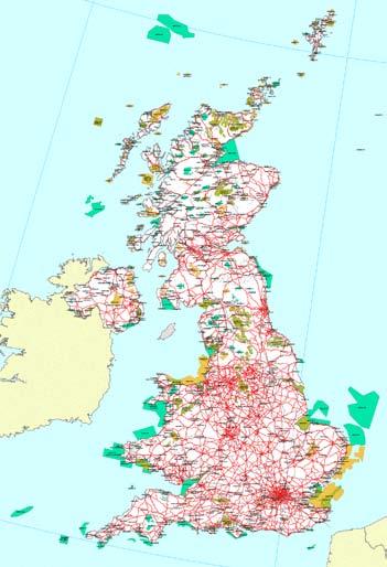


75 - 69 -

76 Figure 55: National Natura 2000 Maps; Ireland (Top LEFT), UK (TOP RIGHT), Spain (CENTRE LEFT), Portugal (CENTRE LEFT) and France (BOTTOM LEFT) and NATURA2000 Legend (BOTTOM RIGHT) 81 Nationally however countries can have other marine protected areas that are designated under national law. The EU provides a database of the Natura2000 sites however the national sites may be more difficult to identify without local knowledge of the appropriate governing body. For example the UK has a number of designations such as the Sites of Special Scientific Interest (SSSI/ASSI), Ramsar Sites, Marine Nature Reserves (MNR), Scottish Marine Protected Areas (MPA) and the latest Marine Conservation Zones (MCZ) 82. These UK MPAs are available on interactive maps available on the JNCC website or the UK MPA Centre website 83. It can be seen from Figure 56 below that there are a number of small protected areas in the identified locations in the west coast of Scotland and also in Wales and Southern England. However the majority of these areas are coastal sites in that they are very close to shore and are unlikely to affect the siting of combined wind and wave devices however they may have an impact on the siting of combined wind and tidal technologies as visibility from shore may be more important near these locations if the protected area is for example protected for its beauty


77 Figure 56: UK MPAs; Scotland (LEFT) and England and Wales (RIGHT) 84 Ireland likewise has a number of nationally designated sites, the GIS datasets and maps for which are downloadable from the Irish National Parks and Wildlife Service website 85. The majority of these sites also appear to be in the near-shore or coastal region and as such, should not impact on the siting of a combined wind and wave project. Figure 57: Irish MPA Maps from the Irish Environmental Protection Agency 86 and the National Parks and Wildlife Services 87 Figure 58 below illustrates the national and European marine protected areas in France. It is evident that there is a large MPA in the north-west tip of France where the wind and wave resource is at its greatest. This will likely affect the siting of a wind-wave combined project or the cable layout
 88 7.5.2 Navigation & Shipping Lanes One of the primary European shipping routes runs from the south coast of England, along the Atlantic coast of France and Portugal to the tip of Gibraltar.")
78 Unfortunately no national information could be found for Spain and Portugal on Atlantic MPAs. Figure 58: French Marine protected areas (Natura 2000 sites, French and Corsican nature reserves marine nature park, national park, etc.) Navigation & Shipping Lanes One of the primary European shipping routes runs from the south coast of England, along the Atlantic coast of France and Portugal to the tip of Gibraltar. From this primary route, tributary routes connect to the relevant ports. Therefore there is a high density of traffic along the north-western tip of France and Spain and the coast of Portugal. The French Atlantic coast, the west coast of England and Wales and the North coast of Spain have a lower traffic density. The west coast of Ireland and Scotland has little to no shipping traffic. It is possible that any projects located off Portugal or North-west Spain and France will have conflicting use with shipping traffic however this may be rectifiable with sufficient lighting and navigational aids


79 Figure 59: Atlantic Ocean: Shipping Routes for North Atlantic (LEFT) and South Atlantic (RIGHT) 89 Country Shipping Density Site Selection Points WIND & WAVE Ireland Low 10 Scotland Low 10 England High 1 Medium 6 France Medium 6 Spain Medium 6 Portugal High 1 WIND & TIDAL Scotland Low 10 Wales Medium 6 England High 1 Table 32: Atlantic Ocean: Shipping Density Site Selection Points

80 7.5.3 Military Exercise Areas National military exercise maps are difficult to acquire without national knowledge and therefore military exercise maps of France, Spain and Portugal could not be found however a detailed map for Scotland can be found in the Scottish Marine Atlas, Figure 60 below and for the UK in the UK Offshore Energy Strategic Environmental Assessment Document. It can be seen that there is significant military activity in the 2 areas identified for combined offshore renewable projects. Fortunately the Firing Danger Areas, outlined in red hatch, are limited to the southern Hebrides. The UK Map of Military Areas, Figure 61, has designated army danger areas off the coast of Wales and Airforce and Navy areas off the south west coast of England. It is possible that some understanding could be reached for an offshore renewable project however this would need to be taken up with the relevant authority in a more in-depth site selection. Figure 60: Scottish Military Exercise Areas

81 Figure 61: UK Military Exercise Areas


82 7.5.4 Oil and Gas Fields Oil and gas exploration is not as prolific in the Atlantic as in the North Sea region however there do exist a number of fields, for example in the Irish Sea shown in Figure 64 below. Figure 62: Oil and Gas Pipelines in Irish Sea 92 Figure 63: Oil and Gas Fields in Northern Europe 92 Figure 64: UK Oil and Gas Fields Fishing Zones The European Atlas of the Seas divides the ORECCA Atlantic Ocean region into 2 seas; the Celtic Seas and the Bay of Biscay and Atlantic Iberian Coast. Figure 65 shows the distribution of the fishing fleet by coastal

83 region in these 2 sea regions. It is evident that, particularly in the north of the Atlantic, there is a large number of fishing ports with greater than 1000 vessels in many of the coastal regions (west Ireland, southwest England, north-west France, north-west Spain and south-west Portugal) in proximity to the locations identified in this section for combined offshore renewable projects. Figure 65: Atlantic Ocean: Distribution of fishing fleet by coastal region and location of fishing ports


84 7.6 Physical characteristics of the Site Seabed Type The seabed surface and materials and given depths is important information for a developer as it will determine the viability of an installation, the foundation or mooring technology required and the cost of installing cabling. The Irish seabed landscape is currently being mapped by the INFOMAR Project seen in Figure 66 below. The Irish Sea and UK waters are modelled by a UK project by the Joint Nature Conservation Committee Figure 67, Figure 68 and Figure 69 below. An EU INTERREG project known as MESH 95 is providing a central forum for researchers working in gathering seabed and habitat data for various European countries. The GEOSEAS 96 Project is an EU FP7 Infrastructures Project aiming to catalogue all available seabed mapping and geotechnical data from studies carried out in European waters. Figure 66: INFOMAR Irish Seabed Mapping Project Map 97 Figure 67: Irish Sea: Marine Landscape

85 Figure 68: Scottish Seabed Type 99 Figure 69: UK SeaMap Seabed Sediments

86 Figure 70: French Seabed Map
87 7.7 Final Selection The following table calculates the final site selection figure for each of the locations considered, which were ranked for each parameter in the preceding sections. Based on these weighting and point allocation assumptions, the North-West of Scotland near the Hebrides is the best fixed combined wind and wave site with a score of 9 out of a possible 10. In reality it may be found that the isolated nature of the islands and the subsequent distance to an available high voltage electrical grid may be economically prohibitive. The second most viable site is a floating wind and wave project off the west coast of Ireland with 8.6 site selection points followed by the floating site off south-west England with 8 points. Both the south-west coast of England fixed site and the north-west coast of France have received equal points of 7.9 each. If the MPAs were included in the points system, it is possible that France would receive slightly less points than England due to the large Natura 2000 site surrounding the high resource area of the North-West coast (Figure 55 above). Parame Scotland Ireland England England Spain France Portugal ter (Fixed) (Floating) (Fixed) (Floating) (Floating) (Fixed) (Floating) Weighting Points Weighted Points Weighted Points Weighted Points Weighted Points Weighted Points Weighted Points Weighted Resour ce Incenti ves Water Depth Locatio n Other Uses Total Table 33: Atlantic Ocean: Combined Wind and Wave Site Selection


88 7.7.1 Site 1 Fixed, high resource area The Scottish location west of the Hebrides Islands received the highest points in all of the considered site parameters with the exception of location for which it received the lowest score. Figure 72 below illustrates the primary ports in the region by draft; the closest deep water port (greater than 20m) is Glasgow with 2 shallower ports available closer to the islands. Figure 71: Scottish Offshore Wind and Wave Resource 99 Figure 72: Scotland Ports


89 7.7.2 Site 2 Floating, high resource area The west coast of Ireland provides the best location for floating combined wind and wave energy projects according to the site selection methodology. Due to the location of ports and grid infrastructure this document is specifically referring to a location west of Connacht. Figure 73: Irish Site Selection Location for combined wind and wave floating The location has received high points for resource and incentives and for other users as there is little shipping, military or oil and gas activity. However it should be noted that there is significant activity in fishing and aquaculture in the area and any potential conflicts with this industry will need to be addressed in more specific site assessment

90 7.7.3 Site 3 High wind and tidal current resource area Figure 74: Atlantic Ocean: Combined Wind and Tidal Locations Based on the site selection methodology outlined in this document, the 3 primary combined wind and tidal sites are located off the island of Islay in Scotland, Carmel Head in Wales and the Bristol Channel in England. It should be noted that this assessment methodology does not take into account the tidal velocities available in the three sites and considers them as sites with a resource greater than 1.75m/s. Therefore although the Scottish site achieves the highest value in the assessment, further research needs to be carried out to determine the actual potential energy output of the 3 sites. Parameter Weighting Scotland Wales England Points Weighted Points Weighted Points Weighted Resource Incentives Water Depth Location Other Uses Total Table 34: Atlantic Ocean: Combined Wind and Tidal Site Selection

91 8 Site Selection Application to: Mediterranean and Black Seas Region The area considered under the Mediterranean and Black Sea region is shown in Figure 33 below. It is an intersection of 3 continents and countries at different stages of development. There is a strong historical link to early navigation and early western civilisation and the region is well known for its mild climate; there is high coastal tourism, fishery and navigation in the region. The preceding site selection methodology outlined in section 5, will be applied to the region in the following section, with the objective of identifying viable sites for combined wind-wave or wind-tidal current sites based on both GIS results compiled in the ORECCA project and available national data. Figure 75: Mediterranean and Black Seas: Region as defined by the EU FP7 ORECCA Project
 for 2 different wind resource levels (6-8m/s and greater than 8m/s at 10m a.s.l).")
92 8.1 Resource Wind & Wave Combination The results of the GIS tool are shown in Figure 34 below. This divides the resource into 6 resource levels, 3 wave resource levels (5-15kW/m, 15-25kW/m and greater than 25kW/m) for 2 different wind resource levels (6-8m/s and greater than 8m/s at 10m a.s.l). The wave resource is the lowest level (i.e. 5-15kW/m) for all relevant areas in the Mediterranean and Black Sea region with the lower wind level predominant (level 1, 6-8m/s at 10ma.s.l.) and 2 locations with the higher wind level, indicated by level 4 (greater than 8m/s at 10m a.s.l.). Figure 76: Mediterranean and Black Seas: Combined Resource Levels with identified potential sites Looking at the OCEANOR and Quikscat data individually, it can be seen that the majority of the area of both seas has an average wave power level of 5-10kW/m with a greater power available off the south coast of France and Spain with 15-20kW/m. A good wind resource exists across both seas with large areas showing average wind speeds of 6-7 and 7-8m/s at 10m a.s.l. and an area off the south coast of France with wind speeds of 8-10m/s
 The Italian Wind Atlas shows average annual wind speeds")

93 Figure 77: Mediterranean and Black Seas: Average Wave Power Levels according to OCEANOR (BOTTOM) and Average Wind Speeds according to Quikscat (TOP) The Italian Wind Atlas shows average annual wind speeds of 6-7m/s at 75m a.s.l. in the north-west of the country and the south-east with wind speeds of 7-8 and 8-9m/s available in the islands of Sicily and Sardinia and in some locations along the Adriatic coast


94 Figure 78: Italian Offshore Wind Atlas 101,102 The French offshore wind map only shows wind speeds very close to shore, however these are shown to be 7-8m/s at 60m a.s.l. along the coastline and 8-9m/s slightly further out. Figure 79: French Offshore Wind Resource: South coast 103 As there are very few areas suitable to wave energy extraction in the region, there likewise are few national wave energy atlases. A wind and wave energy atlas of the Mediterranean is available for purchase as a result of the MedAtlas project and was produced by the Western European Armaments Organisation
95 Research Cell (WEAO) 104. Likewise a wind and wave atlas of the Hellenic seas is available for purchase 105 on request. Based on the available wind and wave resource data, there are no prominent sites that would be suitable for combined wind and wave projects. The south coast of France may provide the greatest combined wind and wave resource in the region with 10-15kW/m. The other potential location is the south-west coast of Sicily based on the resource
 There are 3")


96 8.1.2 Wind & Tidal Current Combination Figure 80: Combined Resource in Mediterranean and Black Sea: wind + wave + tidal current (circled) There are 3 primary locations for ocean and tidal currents in the Mediterranean and Black Sea region; the Straits of Gibraltar, Straits of Messina and the Bosporus Straits and Aegean Sea. These 3 locations are clearly identified in Figure 80 above and more specifically marked in navy in Figure 43 below and overlayed on the Quikscat wind speed map
 and Aegean Sea and Bosporus Straits (BOTTOM) 8.1.")

97 Figure 81: Primary Locations of Ocean Currents in the Mediterranean and Black Sea based on GIS datasets; Straits of Gibraltar (TOP LEFT), Straits of Messina (TOP RIGHT) and Aegean Sea and Bosporus Straits (BOTTOM) Application of Site Selection Methodology Therefore applying these resource figures to the site selection methodology, the following are the rankings given to each site: Country Resource Level Site Selection Points WIND & WAVE France Level 4 3 Italy Level 1 2 WIND & TIDAL Gibraltar Level 2 8 Sicily Level 2 8 Aegean Level 1 10 Table 35: Atlantic Ocean: Wind & Wave Resource Site Selection Ranking

98 8.2 Incentives and RE Targets Italy provides the best production incentives in the region by far with 0.18/kWh for offshore wind and the greatest available feed-in tariff in Europe for ocean energy with 0.34/kWh giving a site selection score of 9.6. In comparison the country with the second highest available incentives is France with 0.13/kWh for offshore wind and 0.15/kWh for ocean energy giving a total site selection score of 4.6. /kwh Wind Ocean Combined Site FiT Price Received Points FiT Price Received Points Selection Greece Spain France Italy Table 36: Mediterranean and Black Seas: National Production Incentives and Wholesale Electricity Prices Points Production incentives enhance the economic feasibility of a project in a given country and give some indication of the political interest of that country in offshore renewable energy. The existing percentage of electricity from renewable sources and the countries NREAP targets for 2020 are also indicative of intent. Figure 82: Mediterranean and Black Seas: Country Specific - Electricity Generated from Renewable Sources (% gross electricity consumption) 106 Table 37 below summarises the figures available in Eurostats and the NREAP summary document from the European Environment Agency. France has one of the lower current percentages of gross electricity consumption coming from renewable energy however they have the highest NREAP targets for offshore wind and ocean energy in the region. Greece, conversely, has the lowest percentage of electricity from renewables but also has the lowest
99 NREAP targets for offshore energy and may be investing in alternative renewable energies such as solar which would be suitable for their climate. Italy has a low percentage of gross electricity consumption and low NREAP targets for offshore energy however it has the highest feed-in tariff for ocean energy in Europe. Country % Gross Electricity Consumption from RE sources (2009) NREAP Targets by 2020 (MW) 107 Offshore Wind Ocean Spain , Italy France , Greece Table 37: Mediterranean and Black Seas: Country Specific NREAP Targets and RE % of Gross Electricity Consumption 8.3 Geography Water Depth The bathymetry of the Mediterranean and Black Sea is very deep (greater than 500m) close to shore as can be seen in Figure 84. Areas with a water depth of less than 500m are limited to the north of the Adriatic Sea, parts of the Aegean Sea and between the coasts of Sicily and Tunisia. Unfortunately if the area available to the GIS query is considered once a depth limit of 500m has been applied, the majority of the high wind and wave regions are removed from the assessment. This depth limit is due to the current restrictions of the latest floating offshore renewable technologies. Fortunately there appear to be shallower waters available in the locations identified by resource (highlighted in Figure 83 below)

100 Figure 83: Mediterranean and Black Seas: Available area with depth and distance from shore limits applied Even in the more shallow areas for combined wind and wave, the water depth is in the floating range of m minimum. The 3 tidal locations appear to also be in the m water depth range which may pose a problem for existing tidal technologies if it is the higher end of this range however more detailed studies would need to be carried out to determine if there are suitable locations for fixed foundations or if a suitable floating tidal technology could be installed at these locations. For the sake of this investigation, we will assume that there are sites of suitable water depth (i.e. approximately 60m) at the three tidal locations. In Figure 84 below the orange circles designate the combined wind and wave locations being considered (i.e. southern France and western Sicily) while the red circles show the combined wind and tidal locations (i.e. Straits of Gibraltar, Straits of Messina and Bosporus Straits)
.")
101 Figure 84: Mediterranean and Black Seas: Bathymetry (Orange Circles designate combined wind+wave sites, Red Circles represent wind+tidal sites) The following table outlines the scoring given to each location based on its bathymetry (assumed to be within the fixed range for tidal). Country Water Depth Range Typical Wind Turbine Structure Site Selection Points WIND & WAVE France Floating 8 Italy Floating 8 WIND & TIDAL Spain Fixed 9 Italy Fixed 9 Greece Fixed 9 Table 38: Atlantic Ocean: Water Depth Site Selection Ranking

102 8.3.2 Distance from Shore Both combined wind and wave locations are within 100km from shore while all tidal sites are likely to be within 20km from shore based on statistics from the GIS tool and Figure 49 below. Figure 85: Mediterranean and Black Seas: Distance from shore boundaries Country Distance from Shore Site Selection Points WIND & WAVE France km 8 Italy km 8 WIND & TIDAL Spain 0-20km 1 Italy 0-20km 1 Greece 0-20km 1 Table 39: Mediterranean and Black Seas: Distance from Shore Site Selection Ranking
 Country Distance from Distance to Distance from Distance to Total Site Deep Water Port Port -")
103 8.4 Infrastructure Ports There is a proliferation of ports in both the Mediterranean and Black Sea with numerous deep and shallow ports available in each of the locations being considered. Figure 86: Mediterranean and Black Seas: Location of Ports (LEFT: Minimum 10-15m draft, RIGHT: All Ports) Country Distance from Distance to Distance from Distance to Total Site Deep Water Port Port - Site Selection Shallow Port Pier - Site Selection Selection Points Points Points WIND & WAVE France Less than 100km km Italy Less than 100km km WIND & TIDAL Spain Less than 100km 10 Less than 50km Italy Less than 100km 10 Less than 50km Greece Less than 100km 10 Less than 50km Table 40: Mediterranean and Black Seas: Distance from Port Site Selection Points

104 8.4.2 Electrical Grid The electrical grid infrastructure in the region is much denser than that of its Northern European counterparts, Ireland, Scotland and Norway. All locations selected in this section are within close proximity to multiple high voltage kV lines in each country with the exception of the wave and wind location off the coast of Sicily. Figure 87: Mediterranean and Black Seas: Electrical Grid Infrastructure (Solid Circles: Wind + Wave Sites, Dotted Circles: Wind + Tidal Sites) Country Local Grid kv Capacity Site Selection Points WIND & WAVE France kV 8 Italy kV 8 WIND & TIDAL Spain kV 8 Italy kV 6 Greece kV 8 Table 41: Mediterranean and Black Seas: Local Grid Site Selection Points Figure 88 below outlines the intended grid infrastructure projects for 2020 which includes a number of subsea cable interconnectors in the Mediterranean and Black Seas. For example the wind-wave identified site west of Sicily will be located in the region of an interconnector to Africa and the grid is due to be upgraded on the island of Sicily which would increase the site selection points for this site
 - TOP: Spain and France, BOTTOM: Italy and Greece 108 8.4.")
 population centres in the region on both sides of the")
105 Figure 88: Mediterranean and Black Seas: Location of Submarine Cables 2020 for identified sites (circled in purple) - TOP: Spain and France, BOTTOM: Italy and Greece Population/Demand Centres The primary cities in the region are marked in Figure 53 below. There are a number of large (greater than 250,000) population centres in the region on both sides of the seas with the least density of cities on the

106 south coast of Spain and France however the Mediterranean is an area of high tourism and so the demand along the coast is likely to increase significantly in the summer months. Figure 89: Mediterranean and Black Seas: Population/Demand Centres
 and the Special Protection Areas (SPA) which are designated under the Habitats Directive")
107 8.5 Other Uses Designated Protected Areas Figure 90: Mediterranean and Black Seas: Designated Marine Protected Areas Natura2000 sites are EU designated protected areas both on-shore and off-shore. The two types of MPAs that are included in the Natura2000 network are the Special Areas of Conservation (SAC) and the Special Protection Areas (SPA) which are designated under the Habitats Directive and the Birds Directive. A European INTERREG Project exists in this region known as MedPAN which is a network of Managers of Marine Protected Areas in the Mediterranean 109. A sister network also exists in the Adriatic Sea, known as AdriaPAN 110. Figure 91 to Figure 94 below show the MPAs as defined nationally in the MedPAN network and as defined under the EEA Natura 2000 network for each country identified in the preceding sections for combined offshore renewable projects. The MedPAN website gives links and contact information for the relevant MPA governing body in each country in the network and a list of relevant legislation. Spain has a number of MPAs on its Mediterranean coast including a location at the top of Gibraltar. This would need to be considered in a more detailed site selection. It is evident that France does not have many MPAs however the existing few are situated along the coast of the identified combined resource area. A project 50km from shore should not have any interaction with these however contact would need to be made with the relevant local authority to ensure this


 Figure 92: French MPA Maps from MEDPAN")
108 Italy has numerous protected areas, which includes a site off the west coast of Sicily in the identified region for combined wind and wave projects. Greece also has numerous protected areas however the majority of these appear to be on the various islands and very few are marine protected areas. Figure 91: Spanish MPA Maps from MEDPAN 111 (LEFT) and EEA 112 (RIGHT) Figure 92: French MPA Maps from MEDPAN 113 (LEFT) and EEA 114 (RIGHT)
 8.5.")
 and EEA 118 (RIGHT) Shipping traffic density is")


109 Figure 93: Italian MPA Maps from MEDPAN 115 (LEFT) and EEA 116 (RIGHT) Navigation & Shipping Lanes Figure 94: Greek MPA Maps from MEDPAN 117 (LEFT) and EEA 118 (RIGHT) Shipping traffic density is generally high in the Mediterranean particularly through the Straits of Gibraltar where all global traffic must enter the basin. The EU funded SAFEMED 119 project provides maritime traffic flows and risk analysis in the Mediterranean basin and a web GIS is available to identify the main ports and traffic routes in the region


110 Figure 95: Mediterranean and Black Seas: Shipping Routes from TOP: Satellite Imagery 120 and BOTTOM: SAFEMED Project 121 It is evident from Figure 95 above that the Straits of Gibraltar wind and tidal site will have the greatest conflict with shipping traffic while the other identified sites appear to have low-medium densities of sea traffic. Country Shipping Density Site Selection Points WIND & WAVE France Medium 6 Italy Low 10 WIND & TIDAL Spain High 1 Italy Low 10 Greece Medium 6 Table 42: Mediterranean and Black Seas: Shipping Density Site Selection Points


111 8.5.3 Military Exercise Areas National military exercise maps are difficult to acquire without national knowledge and therefore military exercise maps could not be found for the relevant countries however the relevant ministry of defence websites are available Oil and Gas Fields Oil and gas exploration in the European part of the Mediterranean Sea is primarily concentrated in the Adriatic coast of Italy and Sicily as can be seen from Figure 96 below. There are also a few fields off the south coast of France and the Atlantic south coast of Spain, identified by red and green dots in the images. The location west of Sicily is the only identified combined offshore renewable site which may be affected by oil and gas activities. Figure 96: Oil and Gas Fields in Mediterranean Sea 122 (TOP: Italy and Greece, BOTTOM: France and Spain)
.")
112 8.5.5 Fishing Zones Figure 65 shows the distribution of the fishing fleet by coastal region in the Mediterranean Basin. It is evident that there is a large number of fishing ports along the Italian and Greek coastlines (indicated by the blue dots). This also shows that there are on average vessels in the most coastal regions all along the European coast of the Mediterranean Sea indicating a very active fishing industry which may need to be considered when implementing a more detailed site selection. Figure 97: Mediterranean and Black Seas: Distribution of fishing fleet by coastal region and location of fishing ports

113 8.6 Physical characteristics of the Site Seabed Type The EU INTERREG project, MESH 124 is provides a forum for researchers working in this area and the GEOSEAS 125 Project is an EU FP7 Infrastructures Project aiming to catalogue all available seabed mapping and geotechnical data from studies carried out in European waters. The European Marine Observation and Data network (EMODnet) Project and habitat types for seas in the EU. Figure 98 below shows the EMODnet map for the western Mediterranean sea however data is also available for the Aegean, Adriatic and Ionian Seas. The Mediterranean is unique in Europe in that it has a protected seagrass known as Posidonia oceanica (identified by green in Figure 98) which tends to grow in shallower waters typically suitable for fixed offshore wind technologies. This grass is identified in the image below off the western tip of Sicily. However it does not seem to exist in the other locations identified as potential combined offshore renewable sites. The majority of the locations have sandy mud, sand or mud as seabed material according to this survey. 126 provides a web GIS of seabed Figure 98: West Mediterranean Sea: Seabed Map
114 8.7 Final Selection Table 43 summarises the final site selection figures for each of the locations considered, which were given points for each parameter in the preceding sections. Based on these weighting and point allocations, the Italian combined wind and wave site appears to be the most promising receiving points of 6.75 while the French site received This is primarily due to the better incentives available in Italy for ocean energy. It should be noted however that these locations both have a much lower wave energy resource than that of the sites chosen in the Atlantic or North Sea. Parameter Weighting France Italy Points Weighted Points Weighted Resource Incentives Water Depth Location Other Uses Total Table 43: Mediterranean and Black Seas: Combined Wind and Wave Site Selection

115 8.7.1 Site 1 Fixed, high resource area The Italian location is situated off the west coast of Sicily. It has been shown in preceding sections however that there are a number of other users of the sea in this region such as oil and gas, MPAs, Posidonia seagrass and potentially fishing also which would need to be considered in a more detailed site selection process in order to accommodate all users of the sea. Seismic activity is an issue unique to the Mediterranean region in Europe and is of particular importance when assessing sites near Italy and Greece. It can be seen from Figure 99 below that there is a significant amount of seismic activity, both in terms of number and magnitude, in the Mediterranean region around Italy and Greece in particular. Figure 99: Distribution of Seismic Activity from

116 8.7.2 Site 3 High wind and tidal current resource area Figure 100: Kobold Tidal Turbine in the Straits of Messina (courtesy of Ponte di Archimede 129 ) The site selection methodology has shown the Italian site in the straits of Messina as the most promising combined wind and tidal location in the region. This is supported by the fact that a floating tidal turbine prototype, the Kobold, was tested in the Straits from and was subsequently connected to the grid 130. It should be noted that this assessment methodology does not take into account the tidal velocities available in the three sites and considers them as sites with a resource greater than 1.75m/s. Parameter Weighting Spain Italy Greece Points Weighted Points Weighted Points Weighted Resource Incentives Water Depth Location Other Uses Total Table 44: Mediterranean and Black Seas: Combined Wind and Tidal Site Selection
Marine Renewables Industry Association. Marine Renewables Industry: Requirements for Oceanographic Measurements, Data Processing and Modelling
 Marine Renewables Industry Association Marine Renewables Industry: Requirements for Oceanographic Measurements, Data Processing and Modelling October 2009 Table of Contents 1. Introduction... 1 2. Measurements
POWER YOUR FUTURE Universidade do Algarve - Faro. 7 th September 2007
 POWER YOUR FUTURE Universidade do Algarve - Faro Wave Energy The experience of wave energy in Portugal Eng.ª Sofia Patrício 7 th September 2007 Topics Wave Energy Resource Wave Energy in Portugal Wave
Characterizing Ireland s wave energy resource
 Snapshots of Doctoral Research at University College Cork 2011 Characterizing Ireland s wave energy resource Brendan Cahill Hydraulics & Maritime Research Centre, UCC Introduction In theory, the energy
THE WAVE CLIMATE IN THE BELGIAN COASTAL ZONE
 THE WAVE CLIMATE IN THE BELGIAN COASTAL ZONE Toon Verwaest, Flanders Hydraulics Research, toon.verwaest@mow.vlaanderen.be Sarah Doorme, IMDC, sarah.doorme@imdc.be Kristof Verelst, Flanders Hydraulics Research,
AGGREGATE DREDGING AND THE MARINE ENVIRONMENT
 AGGREGATE DREDGING AND THE MARINE ENVIRONMENT The marine Aggregate Levy Sustainability Fund ( marine ALSF ) programme represents one of the most substantial investments in UK marine research. The research
WINDSPEED. Resultat og erfaringer med MSP. 26. september 2013 Hans Chr. Sørensen, SPOK ApS. Contract number: EIE/07/759/S
 WINDSPEED Resultat og erfaringer med MSP 26. september 2013 Hans Chr. Sørensen, SPOK ApS Contract number: EIE/07/759/S12.499460 www.windspeed.eu Background H C Sørensen Business and university background
HELCOM Submerged and The Nairobi International Convention. HELCOM Submerged Expert Group meeting in Bonn, Germany, 22 nd of April 2015
 HELCOM Submerged and The Nairobi International Convention HELCOM Submerged Expert Group meeting in Bonn, Germany, 22 nd of April 2015 The Nairobi International Convention on the Removal of Wrecks 2007
Offshore wind power in the Baltic sea
 Offshore wind power in the Baltic sea Conditions for profitability Henrik Malmberg 2014-09-27 Content BACKGROUND... 2 PURPOSE... 2 ABOUT THE AUTHOR... 2 RELEVANT ISSUES... 3 WIND CONDITIONS AND ENERGY
Best Practice Guidance for Assessing the Financial Performance of Fishing Gear: Industry-led gear trials
 Best Practice Guidance for Assessing the Financial Performance of Fishing Gear: Industry-led gear trials Prepared for The UK Fisheries Economic Network (UKFEN) by Seafish Introduction and Background Reducing
The Marking of Offshore Wind Farms. Provide guidance for a response to IALA. M-4 B445.8 &.9 (& B for on-shore wind farms).
.") CSPCWG2-INF 2 The Marking of Offshore Wind Farms Submitted by: Executive Summary: Chairman (from IALA via IHB) Provide guidance for a response to IALA. Does the Related Project reference have any impact
CSPCWG2-INF 2 The Marking of Offshore Wind Farms Submitted by: Executive Summary: Chairman (from IALA via IHB) Provide guidance for a response to IALA. Does the Related Project reference have any impact
Coastal and marine recreation in New England is ingrained in the region s economic and
 RECREATION Coastal and marine recreation in New England is ingrained in the region s economic and social fabric. Recreation on the ocean and coast includes many of New Englanders most time-honored and
US Offshore Wind An Industry in the Making
 US Offshore Wind An Industry in the Making November 14, 2017 Alla Weinstein Founder, Trident Winds LLC Trident Winds Page 2 Agenda Offshore Wind Development in the US Governing bodies Resource potential
International regulations and guidelines for maritime spatial planning related to safe distances to multiple offshore structures (e.g.
 International regulations and guidelines for maritime spatial planning related to safe distances to multiple offshore structures (e.g. wind farms) Introduction This is a summary of the most important international
RESEARCH Massachusetts Recreational Boater Survey. Project Summary
 Coastal and Marine Spatial Planning RESEARCH Project Summary 2010 Massachusetts Recreational Boater Survey The 2010 Massachusetts Recreational Boater Survey gathered spatial and economic data relating
Fisheries Resource Access Mapping Project (FishRAMP):
:") Fisheries Resource Access Mapping Project (FishRAMP): The Co. Down Wind Resource Zone Contributors: Matthew Service and Laurence Rooney (AFBI); Rod Cappell (Poseidon); Lynn Gilmore (Seafish) and the NI
Fisheries Resource Access Mapping Project (FishRAMP): The Co. Down Wind Resource Zone Contributors: Matthew Service and Laurence Rooney (AFBI); Rod Cappell (Poseidon); Lynn Gilmore (Seafish) and the NI
DUXBURY WAVE MODELING STUDY
 DUXBURY WAVE MODELING STUDY 2008 Status Report Duncan M. FitzGerald Peter S. Rosen Boston University Northeaster University Boston, MA 02215 Boston, MA 02115 Submitted to: DUXBURY BEACH RESERVATION November
Admiralty Inlet Pilot Tidal Project FERC No Appendix C. Derelict Gear Monitoring Plan
 Appendix C Derelict Gear Monitoring Plan ADMIRALTY INLET PILOT TIDAL PROJECT FERC PROJECT NO. 12690 DERELICT GEAR MONITORING PLAN (submitted with the Final Application for a New Pilot Project License)
April 7, Prepared for: The Caribbean Disaster Emergency Response Agency Prepared by: CEAC Solutions Co. Ltd.
 April 7, 2006 Prepared for: The Caribbean Disaster Emergency Response Agency Prepared by: Introduction CEAC Solutions Co. Ltd was commissioned in May 2005 to prepare coastal beach erosion hazard maps for
A GIS APPROACH TO EVALUATE BUS STOP ACCESSIBILITY
 Advanced OR and AI Methods in Transportation A GIS APPROACH TO EVALUATE BUS STOP ACCESSIBILITY Giuseppe SALVO 1, Simona SABATINI 2 Abstract. This paper proposes a methodology to assess public transportation
Task 16: Impact on Lummi Cultural Properties
 Gateway Pacific Terminal Vessel Traffic and Risk Assessment Study Task 16: Impact on Lummi Cultural Properties Prepared for Pacific International Terminals, Inc. Prepared by The Glosten Associates, Inc.
Offshore Wind Energy Stringent quality assurance and quality control. Coastal and Freshwater Fast responding and flexible organisation
 Services Oceanographic and Positioning Equipment Rental Meteorological and Oceanographic Surveys Data Analysis and Characterisation Marine Energy Resource Assessment Real-Time Monitoring Founded in 2010,
Scottish Hydro Electric Power Distribution Operation, Inspection, Maintenance and Decommissioning Strategy Bute Cumbrae Cable Replacement
 SHEPD Section ID 154 Scottish Hydro Electric Power Distribution Operation, Inspection, Maintenance and Decommissioning Strategy Bute Cumbrae Cable Replacement Contents Definitions and Abbreviations...
THE CHALLENGES OF A LARGE-AREA BATHYMETRIC SURVEY
 THE CHALLENGES OF A LARGE-AREA BATHYMETRIC SURVEY Agenda: - Introduction - Tender - Project Planning - Survey - Processing - Delivery - Conclusion 2 Introduction We know less of the oceans at our feet,
Proposed UK Offshore Renewable Energy Installations (OREI) - Guidance on Navigational Safety Issues.
 - Guidance on Navigational Safety Issues.") M MARINE GUIDANCE NOTE MGN xxxxx (M) Proposed UK Offshore Renewable Energy Installations (OREI) - Guidance on Navigational Safety Issues. Notice to Other UK Government Departments, Offshore Renewable Energy
M MARINE GUIDANCE NOTE MGN xxxxx (M) Proposed UK Offshore Renewable Energy Installations (OREI) - Guidance on Navigational Safety Issues. Notice to Other UK Government Departments, Offshore Renewable Energy
La Rance tidal power plant in La Rance, France. Tidal and Wave Energy
 La Rance tidal power plant in La Rance, France Tidal and Wave Energy Tides Tides are caused by the pull of the moon. Tides involve the rise and fall of sea levels. Around the coast of Ireland, the sea
Chapter 20.0 Marine Noise and Vibration
 Chapter 20.0 Marine Noise and Vibration www.tidallagoonswanseabay.com www.tidallagooncardiff.com 20.0 Marine Noise and Vibration 20.1 Overview of existing situation 20.1.0.1 Estuaries by their nature (relatively
INTERNATIONAL HYDROGRAPHIC SURVEY STANDARDS
 INTERNATIONAL HYDROGRAPHIC SURVEY STANDARDS by Gerald B. MILLS 1 I. Background The International Hydrographic Organization (IHO) traces its origin to the establishment of the International Hydrographic
Eastern Shore Islands Area of Interest Community Newsletter
 Eastern Shore Islands Area of Interest Community Newsletter Fall 2018 1ỊNTRODUCTION In addition to information on our Fisheries and Oceans Canada (DFO) website, we have now created a seasonal, community
FishRamp Irish Sea VMS
 2015 FishRamp Irish Sea VMS Laurence Rooney AFBI 24/02/2015 Contents Summary Page 2 Data and Method details Page 4 Overview of competing interests Page 6 GB designated Wind-farms in the Irish Sea Page
Ocean Energy in Ireland
 Ocean Energy in Ireland Engineers Ireland, Midlands Region Fergus Sharkey, Technology Integration Engineer, ESB Ocean Energy 25 th February 2012 Agenda ESB and Ocean Energy Ocean Energy in Ireland Wave
GNSS Technology for the Determination of Real-Time Tidal Information
 GNSS Technology for the Determination of Real-Time Tidal Information Benjamin Kidder C-Nav Positioning Solutions European region Outline of Topics Covered Introduction to Tides Past and Present Methods
Ocean Energy Policy Brief
 Ocean Energy Policy Brief August 2013 Author and Primary Contact Prof JL (Wikus) van Niekerk wikus@sun.ac.za +27 (0)21 808 4251 Summary: South Africa has an exploitable wave energy resource that compares
Taking Stock: Building an Offshore Wind Research Agenda for the U.S. Industry
 Taking Stock: Building an Offshore Wind Research Agenda for the U.S. Industry Walt Musial Manager Offshore Wind National Renewable Energy Laboratory 2016 MRP Workshop December 15, 2016 Pioneering Offshore
Marine Debris from Land to Sea: Holistic Characterization, Reduction and Education Efforts in New Hampshire
 Marine Debris from Land to Sea: Holistic Characterization, Reduction and Education Efforts in New Hampshire ABSTRACT Over time, the focus of marine debris research and work has shifted away from simply
Advanced PMA Capabilities for MCM
 Advanced PMA Capabilities for MCM Shorten the sensor-to-shooter timeline New sensor technology deployed on off-board underwater systems provides navies with improved imagery and data for the purposes of
Wind Energy 101 for Southeastern Policy Makers Overview of Wind Energy Development and Potential in the US
 Wind Energy 101 for Southeastern Policy Makers Overview of Wind Energy Development and Potential in the US Jim Doane, Senior Engineer March 2012, Charlotte, North Carolina, USA Agenda Introduction to PMSS
Determining bicycle infrastructure preferences A case study of Dublin
 *Manuscript Click here to view linked References 1 Determining bicycle infrastructure preferences A case study of Dublin Brian Caulfield 1, Elaine Brick 2, Orla Thérèse McCarthy 1 1 Department of Civil,
Wave Energy Atlas in Vietnam
 Wave Energy Atlas in Vietnam Nguyen Manh Hung, Duong Cong Dien 1 1 Institute of Mechanics, 264 Doi Can Str. Hanoi, Vietnam nmhungim@gmail.com; duongdienim@gmail.com Abstract Vietnam has achieved remarkable
General Guidance on the Voluntary Interim Application of the D1 Ballast Water Exchange Standard in the North-East Atlantic and the Baltic Sea
 General Guidance on the Voluntary Interim Application of the D1 Ballast Water Exchange Standard in the North-East Atlantic and the Baltic Sea All 21 countries in HELCOM and OSPAR have signed up to the
Computational Fluid Dynamics
 Computational Fluid Dynamics A better understanding of wind conditions across the whole turbine rotor INTRODUCTION If you are involved in onshore wind you have probably come across the term CFD before
15B. Contents. Introduction...1. MGN 543 Checklist...1. Methodology Checklist INCH CAPE OFFSHORE LIMITED
 Contents Introduction...1 MGN 543 Checklist...1 Methodology Checklist... 14 www.inchcapewind.com i Introduction 1 The Maritime and Coastguard Agency (MCA) has developed a checklist in conjunction with
G+ Global offshore wind health and safety organisation
 G+ Global offshore wind health and safety organisation 2016 incident data report www.gplusoffshorewind.com About the G+ Global offshore wind health and safety organisation The primary aim of the G+ is
The development of the historical harbour of Paphos, Cyprus H.J. van Wijhe*, M. Meletiou^ Division, P.O. Box 152, 8300 AD Emmeloord, The Netherlands
 The development of the historical harbour of Paphos, Cyprus H.J. van Wijhe*, M. Meletiou^ Division, P.O. Box 152, 8300 AD Emmeloord, The Netherlands Abstract The harbour of Paphos originates from ancient
Currents measurements in the coast of Montevideo, Uruguay
 Currents measurements in the coast of Montevideo, Uruguay M. Fossati, D. Bellón, E. Lorenzo & I. Piedra-Cueva Fluid Mechanics and Environmental Engineering Institute (IMFIA), School of Engineering, Research
Influence of wind direction on noise emission and propagation from wind turbines
 Influence of wind direction on noise emission and propagation from wind turbines Tom Evans and Jonathan Cooper Resonate Acoustics, 97 Carrington Street, Adelaide, South Australia 5000 ABSTRACT Noise predictions
The Maritime Law Association of Australia and New Zealand
 The Maritime Law Association of Australia and New Zealand Protecting the Environment and Promoting Safe Navigation: Australia s System of Pilotage in the Torres Strait Adam McCarthy Assistant Secretary
Cycle traffic and the Strategic Road Network. Sandra Brown, Team Leader, Safer Roads- Design
 Cycle traffic and the Strategic Road Network Sandra Brown, Team Leader, Safer Roads- Design Highways England A Government owned Strategic Highways Company Department for Transport Road Investment Strategy
Marine Protected Areas (MPAs)
") Marine Protected Areas This is one of a series of guides in which Seafish explores topical issues affecting the UK seafood industry. This guide takes a practical look at : what they are, the different
Marine Protected Areas This is one of a series of guides in which Seafish explores topical issues affecting the UK seafood industry. This guide takes a practical look at : what they are, the different
MIKE Release General product news for Marine software products, tools & features. Nov 2018
 MIKE Release 2019 General product news for Marine software products, tools & features Nov 2018 DHI 2012 MIKE 3 Wave FM New advanced phase-resolving 3D wave modelling product A MIKE 3 FM Wave model - why?
Sustainable Fisheries for Future Generations The Fisheries White Paper
 Sustainable Fisheries for Future Generations The Fisheries White Paper Key messages The Fisheries White Paper Sustainable Fisheries for Future Generations charts the course for a sustainable and profitable
APPENDIX G WEATHER DATA SELECTED EXTRACTS FROM ENVIRONMENTAL DATA FOR BCFS VESSEL REPLACEMENT PROGRAM DRAFT REPORT
 APPENDIX G WEATHER DATA SELECTED EXTRACTS FROM ENVIRONMENTAL DATA FOR BCFS VESSEL REPLACEMENT PROGRAM DRAFT REPORT Prepared for: B.C. Ferries Services Inc. Prepared by: George Roddan, P.Eng. Roddan Engineering
OFFSHORE WIND: A CRASH COURSE
 OFFSHORE WIND: A CRASH COURSE OFFSHORE WIND: DEFINED OFFSHORE WIND: Construction of wind farms in bodies of water to generate electricity from wind. Unlike the typical usage of the term offshore in the
IMPACTS OF COASTAL PROTECTION STRATEGIES ON THE COASTS OF CRETE: NUMERICAL EXPERIMENTS
 IMPACTS OF COASTAL PROTECTION STRATEGIES ON THE COASTS OF CRETE: NUMERICAL EXPERIMENTS Tsanis, I.K., Saied, U.M., Valavanis V. Department of Environmental Engineering, Technical University of Crete, Chania,
Appendix 21 Sea angling from the shore
 Appendix 21 Sea angling from the shore LUC SMRTS2015 Final Report 342 March 2016 Appendix 21 Sea angling from the shore Table A21.1: Summary of sample confidence levels Responses Spatial data Questionnaire
Report of the Committee to Study Offshore Wind Energy and the Development of Other Ocean Power Technology
 Report of the Committee to Study Offshore Wind Energy and the Development of Other Ocean Power Technology HB 1312 (Chapter 180, Laws of 2014) Membership Representative Robert Cushing, Chair Representative
A Comparison of the UK Offshore Wind Resource from the Marine Data Exchange. P. Argyle, S. J. Watson CREST, Loughborough University, UK
 A Comparison of the UK Offshore Wind Resource from the Marine Data Exchange P. Argyle, S. J. Watson CREST, Loughborough University, UK Introduction Offshore wind measurements are scarce and expensive,
Evolution of Deepwater Coral Protection in the Southeast U.S
 Evolution of Deepwater Coral Protection in the Southeast U.S Tina Udouj, Florida Fish and Wildlife Conservation Commission Roger Pugliese, South Atlantic Fishery Management Council Overview Deepwater Corals
Can we minimize the impact of vessel moorings on coastal habitats? An interagency management approach in Queensland
 Can we minimize the impact of vessel moorings on coastal habitats? An interagency management approach in Queensland Kurt Derbyshire 1, Rebecca Batton 1, Nicola Udy 2, Kimberly Foster 3 and Richard Marsh
Energy from seas and oceans
 Energy from seas and oceans Marine energy can represent an important source of renewable energy in the near future. In Italy, activities performed in this sector are growing rapidly both in terms of assessment
NEED FOR SUPPLEMENTAL BATHYMETRIC SURVEY DATA COLLECTION
 305 West Grand Avenue, Suite 300 Montvale, New Jersey 07645 Phone 201.930.9890 Fax 201.930.9805 www.anchorqea.com M EMORANDUM To: Caroline Kwan and Nica Klaber U.S. Environmental Protection Agency Region
World Shipping Council. National Oceanographic and Atmospheric Administration
 Comments of the World Shipping Council Submitted to the National Oceanographic and Atmospheric Administration In the matter of Endangered and Threatened Species; Petition for Rulemaking to Establish a
Trawl fishery management of Eastern Arabian Sea
 Trawl fishery management of Eastern Arabian Sea Dr. A.P.Dineshbabu, Central Marine Fisheries Research Institute, India Existing management practices Seasonal closure of fishery: The regulations for closed
July Ballast Water Management FAQ
 July 2018 Ballast Water Management FAQ Contents Contents... i Forward... iii 1. Has the UK ratified the BWM Convention?... 5 2. To what ships does the Convention apply?... 5 2.1 Internationally operating
Proposed Marine Park in the Brothers Islands
 Proposed Marine Park in the Brothers Islands PURPOSE This paper presents the preliminary plan of the proposed marine park in the Brothers Islands (BIMP) for protection and enhancement of Chinese White
Offshore engineering science
 Offshore engineering science In this research stream theoretical models advanced geotechnical models and new numerical techniques were used in applied offshore engineering topics such as loading, design
Beach Wizard: Development of an Operational Nowcast, Short-Term Forecast System for Nearshore Hydrodynamics and Bathymetric Evolution
 Beach Wizard: Development of an Operational Nowcast, Short-Term Forecast System for Nearshore Hydrodynamics and Bathymetric Evolution Ad Reniers Civil Engineering and Geosciences, Delft University of Technology
17. High Resolution Application of the Technology Development Index (TDI) in State Waters. South of Block Island
 in State Waters. South of Block Island") 17. High Resolution Application of the Technology Development Index (TDI) in State Waters South of Block Island for the Rhode Island Ocean Special Area Management Plan 2010 by Annette Grilli 1, Malcolm
17. High Resolution Application of the Technology Development Index (TDI) in State Waters South of Block Island for the Rhode Island Ocean Special Area Management Plan 2010 by Annette Grilli 1, Malcolm
SeaSmart. Jonathan Evans
 SeaSmart A new approach for rapid, on-site resource assessment at potential tidal stream energy array sites using MAS Marine Solutions for the Deep Data World Jonathan Evans Presentation Outline Marine
Contributions from a multidisciplinary university Finn Gunnar Nielsen Professor Geophysical Institute
 Workshop Floating Offshore Wind Norwegian Offshore Wind Cluster Dublin 4 th and 5 th December 2018 Contributions from a multidisciplinary university Finn Gunnar Nielsen Professor Geophysical Institute
Press release LAUNCH. FlanSea WAVE PIONEER Wave energy converter
 LAUNCH FlanSea WAVE PIONEER Wave energy converter TUESDAY 23 APRIL 2013 VLIZ - Flanders Marine Institute WANDELAARKAAI 7, B-8400 OOSTENDE BELGIUM Press release FlanSea WAVE PIONEER THE FORCE OF THE WAVES
DIGITAL SOLUTIONS TRAINING CATALOGUE. QRA and CFD simulation. Phast, Safeti and KFX SAFER, SMARTER, GREENER
 DIGITAL SOLUTIONS TRAINING CATALOGUE QRA and CFD simulation Phast, Safeti and KFX SAFER, SMARTER, GREENER 02 PHAST, SAFETI AND KFX Training catalogue Global training Our increased focus on global training,
Walking up Scenic Hills: Towards a GIS Based Typology of Crowd Sourced Walking Routes
 Walking up Scenic Hills: Towards a GIS Based Typology of Crowd Sourced Walking Routes Liam Bratley 1, Alex D. Singleton 2, Chris Brunsdon 3 1 Department of Geography and Planning, School of Environmental
Burbo Bank Extension Offshore Wind Farm
 Burbo Bank Extension Offshore Wind Farm Developer: DONG energy Site Size: Covering an area of approximately 40 km² Site Location: The proposed project would be located west of the operational Burbo Bank
Examples of Carter Corrected DBDB-V Applied to Acoustic Propagation Modeling
 Naval Research Laboratory Stennis Space Center, MS 39529-5004 NRL/MR/7182--08-9100 Examples of Carter Corrected DBDB-V Applied to Acoustic Propagation Modeling J. Paquin Fabre Acoustic Simulation, Measurements,
BASELINE SURVEY, VISUAL - SITE SPECIFIC
 BASELINE SURVEY, VISUAL - SITE SPECIFIC Introduction As stated in SEPA s policy and in the Fish Farm Manual (1998), scientific data are required by SEPA in order to assess the existing condition on the
Chagrin River TMDL Appendices. Appendix F
 Appendix F The following are excerpts from the Eastern Brook Trout Joint Venture s Conservation Strategy (Working Draft v.6), Conserving the Eastern Brook Trout: Strategies for Action Found at: http://www.easternbrooktrout.org/constrategy.html
Inlet Management Study for Pass-A-Grille and Bunces Pass, Pinellas County, Florida
 Inlet Management Study for Pass-A-Grille and Bunces Pass, Pinellas County, Florida Final Report Submitted By Ping Wang, Ph.D., Jun Cheng Ph.D., Zachary Westfall, and Mathieu Vallee Coastal Research Laboratory
Wind and Tidal - Benefits and Opportunities in Australia
 Wind and Tidal - Benefits and Opportunities in Australia Presented by MR MATTHEW KEYS, BEng (Civil) Lead Analysis Engineer Carnegie Corporation Ltd 2007 Carnegie Corporation Ltd Outline Ocean Energy Introduction
Energy capture performance
 Energy capture performance Cost of energy is a critical factor to the success of marine renewables, in order for marine renewables to compete with other forms of renewable and fossil-fuelled power generation.
NATIONAL MARINE FISHERIES SERVICE (NMFS) REPORT ON HIGHLY MIGRATORY SPECIES (HMS) ACTIVITIES
 REPORT ON HIGHLY MIGRATORY SPECIES (HMS) ACTIVITIES") Agenda Item J.1.a NMFS Report 1 March 2019 NATIONAL MARINE FISHERIES SERVICE (NMFS) REPORT ON HIGHLY MIGRATORY SPECIES (HMS) ACTIVITIES Deep-set Buoy Gear (DSBG) Authorization and National Environmental
Agenda Item J.1.a NMFS Report 1 March 2019 NATIONAL MARINE FISHERIES SERVICE (NMFS) REPORT ON HIGHLY MIGRATORY SPECIES (HMS) ACTIVITIES Deep-set Buoy Gear (DSBG) Authorization and National Environmental
The impact of different means of transport on the operation and maintenance strategy for offshore wind farms
 The impact of different means of transport on the operation and maintenance strategy for offshore wind farms W.A.A.M. Bierbooms, M Sc.; G.J.W. van Bussel, PhD * Section Wind Energy, Faculty Civil Engineering
GD 0043/18 ACTIVE TRAVEL STRATEGY
 GD 0043/18 ACTIVE TRAVEL STRATEGY 2018-2021 May 2018 Minister s Introduction There is strong evidence that regular physical activity reduces the risk of a range of health conditions. The best way to increase
PRESIDENCY WORKING DOCUMENT
 COUNCIL OF THE EUROPEAN UNION Brussels, 28 May 2003 DS 208/03 LIMITE PRESIDCY WORKING DOCUMT Proposal for a COUNCIL REGULATION on the management of the fishing effort relating to certain Community fishing
EXISTING AND PLANNED STRATEGIES AND ACTIONS CONNECTED WITH COASTAL PROTECTION IN ASPECT OF PREDICTED SEA LEVEL RISE
 EXISTING AND PLANNED STRATEGIES AND ACTIONS CONNECTED WITH COASTAL PROTECTION IN ASPECT OF PREDICTED SEA LEVEL RISE Andrzej Cieślak Long term coastal protection strategy In 2000 a new 1 Polish long term
CROSS-SHORE SEDIMENT PROCESSES
 The University of the West Indies Organization of American States PROFESSIONAL DEVELOPMENT PROGRAMME: COASTAL INFRASTRUCTURE DESIGN, CONSTRUCTION AND MAINTENANCE A COURSE IN COASTAL DEFENSE SYSTEMS I CHAPTER
Table of Contents. Bakkafjara Ferry Port. Icelandic Maritime Administration. Review of IMA provided reports. 1 General
 Icelandic Maritime Administration Bakkafjara Ferry Port Review of IMA provided reports COWI A/S Parallelvej 2 DK-2800 Kongens Lyngby Denmark Tel +45 45 97 22 11 Fax +45 45 97 22 12 wwwcowicom Table of
Sustainable Energy Science and Engineering Center. Ocean Energy. Reference: Renewable Energy by Godfrey Boyle, Oxford University Press, 2004.
 Ocean Energy Reference: Renewable Energy by Godfrey Boyle, Oxford University Press, 2004. Ocean Energy Oceans cover most of the (70%) of the earth s surface and they generate thermal energy from the sun
T H E A R E A I N VO LV E D
 SEABED DREDGING: THE AREA INVOLVED In the past thirty years the UK marine aggregate industry has become a major supplier of sand and gravel for the UK and European construction industries and domestic
South Bay Coastal Ocean Observing System California Clean Beaches Initiative
 South Bay Coastal Ocean Observing System California Clean Beaches Initiative Quarterly Report September 2003 to City of Imperial Beach Eric Terrill 1 1 Scripps Institution of Oceanography, University of
High seas: conservation and management measures to prevent significant adverse impacts on vulnerable marine ecosystems
 High seas: conservation and management measures to prevent significant adverse impacts on vulnerable marine ecosystems ABSTRACT Australia has consented to implement the interim measures adopted in 2007
WAVE FORECASTING FOR OFFSHORE WIND FARMS
 9 th International Workshop on Wave Hindcasting and Forecasting, Victoria, B.C. Canada, September 24-29, 2006 WAVE FORECASTING FOR OFFSHORE WIND FARMS Morten Rugbjerg, Ole René Sørensen and Vagner Jacobsen
INTRODUCTION SEAS AND OCEANS: A PRECIOUS RESOURCE KEY FACTS
 6 ~ SEAS FOR LIFE INTRODUCTION SEAS AND OCEANS: A PRECIOUS RESOURCE We all benefit from our seas and oceans. In addition to the more traditional uses like transport, fishing, aquaculture, tourism and recreation,
gaf traffic 2015 capability statement
 gaf traffic 2015 capability statement www.gaftraffic.com.au INTRODUCING GAF TRAFFIC GAF Traffic is a people-centred traffic engineering consultancy serving new and existing projects in Western Australia.
UK Coastal Atlas of Recreational Boating 2.0: User Guide
 UK Coastal Atlas of Recreational Boating 2.0: User Guide Royal Yachting Association September 2016 RYA UK Coastal Atlas of Recreational Boating 2.0 Contents 1. Overview... 2 1.1. What is it?... 2 1.2.
ROV Development ROV Function. ROV Crew Navigation IRATECH SUB SYSTEMS 2010
 IR AT EC H SU B SY ST EM S 20 10 Remotely Operated Vehicle ROV INTRODUCTORY 2008 2008 1 KEY POINTS ROV Introductory ROV Development ROV Function Types of ROV ROV Crew Navigation ROV Components 2 ROV Development
University of Victoria Campus Cycling Plan Terms of Reference. 1.0 Project Description
 University of Victoria Campus Cycling Plan Terms of Reference 1.0 Project Description The Campus Cycling Plan, a first for the University, will provide a comprehensive and coordinated approach to support
MICROPHONE WIND SPEED LIMITS DURING WIND FARM NOISE MEASUREMENTS
 MICROPHONE WIND SPEED LIMITS DURING WIND FARM NOISE MEASUREMENTS Abstract Jon Cooper 1 and Tom Evans 2 1 Resonate Acoustics, Level 1/23 Peel St, Adelaide SA 5000, Australia Email: jon.cooper@resonateacoustics.com
V Complying with IHO S-52/S-63/S-64
 Model FEA-2107/2807 V.06.50 Complying with IHO S-52/S-63/S-64 The software has been upgraded to V.06.50 in accordance with the IHO standards. IHO S-52 Ed. 6.1.1 Specifications for Chart Contents and Display
EXECUTIVE SUMMARY. Argyll Marine Special Areas of Conservation
 Argyll Marine Special Areas of Conservation Legislative Background Under the Habitats Directive (Council Directive 92/43/EEC on the conservation of natural habitats and of wild fauna and flora), Loch Creran
Dutch offshore wind energy developments:
 Dutch offshore wind energy developments: roadmap 2023 roadmap 2030 Joost Vermeulen sr. policy advisor offshore wind energy programme Offshore wind energy development in NL Existing wind farms Size: 1 GW