Road Safety Design Guidelines for Bus Rapid Transit in Indian Cities with consideration for local accessibility and traffic capacity
|
|
|
- Silas Carson
- 5 years ago
- Views:
Transcription


1 Road Safety Design Guidelines for Bus Rapid Transit in Indian Cities with consideration for local accessibility and traffic capacity Draft version October 2012
2 CHAPTERS 1. Background to the Guidelines BRT in the Indian Context General BRT Design Guidelines The BRT Midblock elements Midblock Pedestrian Crossings Midblock U-turns Midblock BRT Stations T-intersection with a Minor Street Four Arm Intersection with Major Road Regular Intersection of Two BRT Corridors Roundabout Intersection of Two BRT Corridors BRT with Express Lane Services BRT Terminals Impact of these Recommendations on Mixed Traffic Capacity Design of Signal Configurations Safety and BRT Passenger Capacity RECOMMENDED DESIGN TEMPLATES Basic Midblock Midblock pedestrian crossing Midblock u-turn + pedestrian crossing Midblock BRT station with pedestrian crossing + u-turn T-intersection with a minor street BRT Intersection with a major road Regular intersection of two BRT corridors Roundabout intersection of two BRT corridors BRT with express lanes BRT terminal... 51

3 1. BACKGROUND TO THE GUIDELINES Bus Rapid Transit In the last few decades, Bus Rapid Transit (BRT) has emerged as a cost-effective, flexible and environmentally sustainable form of public transportation. The world s first BRT was developed in Curitiba, Brazil, which was followed by the development of many other BRTs across Latin America, notably the TransMilenio BRT in Bogota, Colombia. Encouraged by the success of these systems, BRTs began to spring up in many cities across the globe. At the time of this writing, there are 146 cities worldwide operating a total number of 3,658 kilometers of BRT, serving just under 24,000,000 passengers per day. These numbers are expected to continue to grow. 1 In India, BRT has received considerable interest, spearheaded by the success of the Ahmedabad BRT. At present, more than 5 Indian cities are developing or augmenting their BRT systems. At the same time, BRT has met with some scepticism, due to the 1 accessed on perceived shortcomings of such systems in a couple of Indian cities. The term, Bus Rapid Transit (BRT), has come to represent a wide range of bus-based, public transportation systems. Although these systems have commonalities, they may also have some very different features. Often, it is the decision of which BRT feature to include or exclude, that determines the success or failure of the system. Picture 1: The TransMilenio BRT in Bogota, Colombia is an example of a system, with all the design features of a full-fledged BRT For the purpose of these Guidelines, we have considered the most common definition of a BRT system, which has, at least, all of the following features: Segregated bus lanes that are meant exclusively for BRT buses; Level-boarding at enclosed bus stations; Intelligent transport systems for commuter information and schedule optimisation; Centralised authority responsible for the development and operations of the BRT. BRT and road safety Road safety is emerging as a major concern, across the developing world, especially in India. India leads the world in the number of road fatalities, with over 130,000 reported each year. Since the country is rapidly urbanising, a growing proportion of these fatalities are beginning to occur in cities. Within cities, the most vulnerable road users are non-motorised transport users, such as pedestrians and bicyclists, who account for about half the share of road fatalities. The greatest perpetrators of road accidents tend to be larger vehicles, such as trucks and buses. Page 1
4 A BRT system typically improves the traffic safety scenario, because it segregates the movement of buses from all other transport modes, and also introduces other changes in the road infrastructure that are associated with safety, such as shorter pedestrian crossings and refuge islands. In particular, a central lane BRT places the buses away from the paths of pedestrians and bicyclists, who are the most vulnerable roads users. Thus, a well executed BRT can significantly reduce road accidents. However, sometimes poorly designed BRT infrastructure may actually have the reverse impact on road safety, if it does not take into consideration its negative impact on local accessibility and vehicular capacity. These aspects of the BRT are discussed in the next two sections respectively. BRT and accessibility A BRT is, generally, built along existing roads with well established mobility and accessibility patterns. The BRT introduces segregated bus lanes, usually fenced off on both sides by guardrails. This segregation tends to impede local accessibility for other transport modes. For example, the BRT guardrails limit opportunities for pedestrians to cross the road. Turning movements for vehicles also become restricted. A BRT that does not take into consideration these impediments may actually end up worsening the road safety scenario. In the Indian context, where both traffic discipline and enforcement are minimal, road users may flout traffic rules and thus create a road safety risk, both for themselves and other road users. For example, pedestrians may resort to jaywalking or jumping the guardrail in order to cross the road. Motor-vehicle drivers, in order to avoid a long detour to take a right turn or u-turn, may resort to driving in the wrong direction, or illegally turning through pedestrian crossings. This is, no doubt, very dangerous for all road users. Thus, poor local accessibility causes road accidents. A BRT design that neglects the local accessibility needs of the population cannot be a safe system. Thus, while the focus of these Guidelines is on road safety, the problems of local accessibility are also considered, as the two issues are interrelated. BRT and traffic capacity A BRT lane generally carries many more times the number of people per lane than the mixed traffic lanes. Yet, the negative impact that BRT has on vehicular capacity is often cited as a criticism against BRT. Critics of BRT argue that the congestion faced by all other traffic completely offsets any benefit of time saved for BRT commuters. This has become a deal breaker for some BRTs in India. Since a BRT is typically built along existing roads, some impact on mixed traffic capacity is unavoidable. However, if a BRT is designed well, it can minimise the negative impact, or better yet, improve throughput capacity. The development of the BRT results in reengineering the road, which may correct previous impediments that were affecting traffic flow. Further, the BRT restricts cross movement to an extent, which can also help in improving throughput capacity. Finally, the BRT takes slow-moving and frequentlystopping buses out off the traffic mix. This also helps to create a smoother traffic flow. However, a poorly designed BRT creates unnecessary bottlenecks that reduce traffic capacity. This is especially true at Page 2
5 intersections, where poor traffic signal management further aggravates the situation. If BRT projects are to find support in India, then it is necessary that the needs of vehicular traffic users are also addressed. Further, if adequate provisions for these roads users are made, then they will be less likely to break traffic rules; such as illegally driving on the BRT lanes. These infringements are also a big cause of road safety problems. About the Guidelines On the one hand, BRTs, like the Ahmedabad BRT, have demonstrated successes in providing cost-effective and efficient public transportation systems for emerging cities. On the other hand, BRT detractors have become more vocal about their arguments against BRT, fuelled by the shortcomings of a couple of BRTs in India. BRT advocates state that it is the most viable public transport system for emerging cities, and the social benefits that accrue from the system far outweigh the negative impact on capacity for private motorised transport. At the same time, there is a growing recognition that for BRT to gain a wider acceptance by all stakeholders, it needs to address the concerns of road safety, local accessibility and capacity for all road users. It is this background that provides the context for these Guidelines. Although the focus of these Guidelines are on road safety, the impacts on local accessibility and road traffic capacity are also considered; as the neglect of the same are often the biggest causes of road safety problems along BRT corridors. These Guidelines are developed out of EMBARQ s experience in conducting road safety audits on a number of BRTs in India and abroad. In India, EMBARQ conducted audits on the BRTs in Ahmedabad, New Delhi and Indore; and the observations from the same have been utilised in developing these Guidelines. Further, EMBARQ has conducted road safety audits on BRTs in North and South American cities, such as Bogota (Colombia), Arequipa (Peru), Mexico City (Mexico) and Rio de Janeiro (Brazil). In addition, in 2012, EMBARQ released draft Guidelines on Traffic Safety on Bus Corridors, which addressed road safety on all bus corridors, (including BRT), in the international context, which has also been used in the development of the Indian Guidelines. Structure of the Guidelines The next chapter of these Guidelines provides our interpretation of the major safety issues for BRT in the Indian context. For instance, we consider the implications of such issues as heterogeneous traffic mix, poor traffic discipline, high pedestrian volume, prevalence of auto-rickshaws, etc. This chapter intends to juxtapose the Indian context against the generic International context, wherein it is argued that international road design best practices may not always be practical in the Indian context. The subsequent chapter discusses general best practices for BRT design, wherein we consider issues such as: median BRT lanes v/s kerb side BRT lanes; full-fledged BRT v/s bus priority or bus way systems; regular flow v/s counterflow; safe design speed, etc. We next illustrate our recommended templates for various sections along a BRT corridor. Each chapter is dedicated to one such element. We start with the basic midblock template. Each subsequent chapter introduces an additional feature, such as pedestrian crossings, u-turns, and BRT stations. Page 3
6 This is followed by chapters on BRT intersection design, wherein we cover both minor as well as major intersections. We also cover issues related to commuter transfers between BRT stations on intersecting BRT corridors. We finally discuss some additional aspects of BRT corridors, such as express lane BRTs and BRT terminals Each chapter consists of a general introduction to the issue at hand; followed by a 3-D, bird s-eye-view model, demonstrating our recommended design template for this element; followed by supporting information about the operational aspects of the proposed design. demonstrated on a fixed road width of 38 meters. BRTs in India are typically developed on urban arterials, with a width of 40 to 60 meters. By choosing a design width marginally below the lower spectrum, we intend to demonstrate how all the various elements of a BRT can be accommodated, without needing additional road width; and without eliminating or reducing the width of other road elements such as traffic lanes, NMT lane or footpath. Although the recommended design templates are focused on road safety, they also take into consideration the impacts on local accessibility and road capacity, both for the BRT and for mixed traffic. These impacts, and measures to minimise the same, have been provided for each sub-section, wherever they are applicable. Unless otherwise stated, all the recommended templates used in these Guidelines, are Page 4

7 2. BRT IN THE INDIAN CONTEXT In many ways, the transportation and traffic scenario in India is different from other countries in the world. Even among developing countries, there are some factors that are very unique to the Indian context. As a result, international best-practices for road safety and street design, especially from developed countries, may not always be relevant or practical in the Indian context. Sometimes, these recommendations may not achieve the desired result, or in other cases, they may even have the counter effect of worsening the road safety scenario. In this chapter, we have documented some of these unique characteristics of transportation and traffic in the Indian scenario. These observations have influenced all the design recommendations that we have proposed in subsequent chapters. Heterogeneous traffic mix In India, especially in smaller cities, the passenger car is not the most dominant motor-vehicle. In many cities, motorised 2- wheelers far outnumber cars in the traffic mix. There also tends to be a high proportion of autorickshaws, used both for passenger and freight transport. Added to this mix, is a wide assortment of buses, trucks and vans of all forms and sizes. Interspersed in between, are non-motorised transport users, as well as, in some cases, animal-powered transport. Thus, road design standards that use the passenger car as the design unit are irrelevant in the Indian context. A road safety intervention that works perfectly for cars may be ineffective for motorbikes. For example, bollards placed along the ramps of footpaths, to prevent cars from mounting the footpath, are incapable of preventing motorbikes from doing the same. Even road capacity calculations, based on Passenger Car Units (PCU) are not easily applicable to the Indian context. A heterogeneous traffic mix, with a high proportion of slow vehicles results in a lower capacity. On the other hand, a high proportion of motorised 2-wheelers may increase road capacity, because of the relative ease by which they can squeeze past other vehicles. Picture 2: In modest Indian cities, cars are not the dominant motor-vehicle, and other vehicles, like motorbikes, tend to have a much larger share in the traffic mix. Bicycles are not the only NMT mode In most developed countries, bicycles are, virtually, the only form of non-motorised transport (NMT). In developing countries like India, apart from bicycles, there are a wide range of NMT modes, such as tricycles (for the disabled), cycle-rickshaws, vendor hand carts, push-carts, etc. NMT infrastructure needs to be designed to be usable by all these modes. For example, Page 5


8 the NMT/bicycle lane needs to be wide enough to accommodate cycle-rickshaws street-vendor pushcarts. Similarly, bollard spacing at pedestrian crossings need to be wide enough to be accessible to larger NMT vehicles. Picture 3: In most Indian cities, the bicycle is only one of many different NMT vehicles, such as tricycles, vendor push-carts, cycle-rickshaws, etc. NMT infrastructure needs to cater for all such vehicle types. High pedestrian density Indian cities are characterised by much higher pedestrian densities than most international cities, outside Asia. This influences the effectiveness of many design standards. For example, in some western countries, it is acceptable for pedestrian crossings to share a signal phase with left-turning vehicles, because the number of pedestrians is not very high. But In the Indian context, this may not be possible due to the sheer volume of pedestrians, and poor traffic discipline, where motorists are unlikely to yield for crossing pedestrians. Picture 4: Indian cities are characterised by high pedestrian densities. Adequate provision needs to be made for pedestrian movement; else they will spill onto the traffic lanes. Poor traffic rules awareness, discipline and enforcement In most Indian cities, traffic discipline is lacking, both by users of motorised and nonmotorised transport. The general awareness of traffic rules is also quite low. Enforcement is also difficult, given the high volume of vehicles and people, and the limited resources available to the traffic police. As a result, traffic discipline cannot be taken as a given in the Indian context. As far as possible, roads must be designed so as to encourage and make it easier for people to understand and follow traffic rules. Concurrently, road features should be adopted, which make it difficult or impossible to break traffic rules. As far as possible, road design should dictate user behaviour, rather than relying on signage and information systems. Further, a systematic assessment needs to be made to understand why people flout traffic rules, and what simple measures can be made to encourage them to follow the rules. Finally, the road should be designed along the principle of forgiving infrastructure ; that means, in case a traffic rule is flouted, it should, as far as possible, not lead to a serious accident. Page 6


9 Picture 5: In the context of poor traffic discipline and enforcement in most Indian cities, road design should, as far as possible, dictate user behaviour. For example, provisions should be made to discourage or make it impossible for motorists to illegally use a pedestrian crossing to make a turn. Abundant road edge development BRTs, in most international cities, are built along major urban arterial roads that are meant to primarily serve thoroughfare traffic. Typically, these arterial roads are very wide, and have long continuous sections without an intersection. Moreover, there tends to be no direct access to properties from these roads. As a result, the demand for vehicles to make right turns or u-turns is quite low. Further, the lack of edge development results in very few pedestrians using this road; so the required footpath width and required number of crossings are both quiet low. In Indian cities, most urban arterial corridors have abundant edge development along the road. These developments are a mixture of residential, institutional, commercial and retail users. As a result, the demand for right or u-turns, and the demand for pedestrian crossings, are both very high. Also, adequate space needs to be provided for vehicles to wait on the side of the road, to load or unload passengers or freight. If adequate provisions are not made for these movements, then it encourages people to break traffic rules, posing a risk to themselves and others. For example, if there are not sufficient right or u-turn opportunities along a long section of the road, then motorists may be induced to illegally drive on the wrong side of the road. Since they are doing something illegal, the tendency is to do it very fast; this creates a risk of head-on collisions with oncoming vehicles, or colliding with pedestrians crossing the road. Picture 6: Urban arterials in most Indian cities are characterised by extensive edge development that have direct access from the main arterial. Such development generates local demand for parking, waiting areas, u-turns, right turns, pedestrian crossings, etc Street vendors and immovable obstructions along the road Many roads in India are characterised by a high volume of street vendors. Often, these vendors locate themselves along the footpath, and their activities spill over to adjacent areas, such as the NMT lane or traffic lanes. Further, there are many immovable, (or very difficult to move), obstacles along the road that impede the smooth flow of traffic and pedestrians. The obstacles could be in the Page 7


10 form of trees, utility boxes, street furniture, religious shrines, encroachments, etc. When faced with an obstacle, the road user leaves his/her path to make his/her way around the obstacle. This puts them into conflict with other vehicles. These obstacles can also create bottlenecks that impact traffic flow. Traffic flow across a midblock is typically determined by the capacity limit at its most constrained point. This inconsistent width of the carriageway encourages excessive speeding in some sections, and leads to congestion-causing bottlenecks in other sections. Auto-rickshaws as the feeder system Auto-rickshaws play an important role, as a para-transit vehicle, in most Indian cities. Yet the infrastructure for this sector is often neglected. This results in auto-rickshaws clustering around areas with a potentially high volume of customers. BRT stations, thus, typically tend to attract a high volume of autorickshaws. If proper infrastructure is not provided for them, they end up queuing along the carriageway. The carriageway width may already be constrained in order to accommodate the BRT station; thus the additional space taken away from the carriageway by the autorickshaws will only worsen the throughput capacity. As vehicles and people jostle their way through these stretches, it creates road safety problems for all road users. Picture 8: Autorickshaws are an important paratransit mode in most Indian cities. If adequate provisions are not made for their needs, they can cause both safety and traffic congestion problems. Picture 7: Obstructions on the footpath make them unusable for pedestrians. Page 8
11 3. GENERAL BRT DESIGN GUIDELINES Overview From 2010 to 2012, EMBARQ conducted an extensive research project, evaluating how different design options for bus corridors impacted pedestrian and traffic safety. 2 The findings from this research informed a set of planning and design guidelines for bus corridors, aimed at maximising safety, while considering impacts on passenger capacity, operating speeds, and accessibility. A pilot version of this guidebook, Traffic Safety on Bus Corridors, was released by EMBARQ in 2012, with a final version to follow in We provide here an overview of the main findings on the safety aspects of BRT that have informed our recommendations. We discuss the safety aspects of various other bus systems, in comparison with the standard segregated central- lane BRT, such as: 2 Duduta, N. et al. Understanding the Traffic Safety Impact of High Performance BRT and Busway Design Features. Transportation Research Record, Journal of the Transportation Research Board, forthcoming Bus priority: Here, buses, for the most part, ply within mixed traffic, but may be provided with some additional priorities, such as bus-only permitted turns, signal priority, etc. Busways: Here, buses run on exclusive lanes, generally on the kerb side, though not necessarily segregated Counterflow systems: Here buses ply in the opposite direction of mixed traffic. This is usually done when a busway runs in both directions on a one-way street. The overall safety impact of a BRT The overall safety impact of implementing a bus system on a corridor depends on the characteristics of the system and the existing conditions on the street. In developing world cities, implementing BRT systems has generally proven to have a positive impact on safety. Other types of corridors, such as busways or bus priority lanes, have not always had the same positive impact. A BRT usually involves eliminating several mixed traffic lanes on a street, separating bus traffic from other modes, and adding or expanding a median, (in the case of centre-lane BRTs), which reduces the length of pedestrian crossings. Bus operations are better organised, commonly replacing a variety of services with a single operating agency with common standards for driver training, vehicle maintenance, etc. Macrobus is a full-fledged BRT in Guadalajara, Mexico, which replaced an existing bus priority lane on a street with heavy traffic. TransMilenio in Bogota, Colombia is another full-fledged BRT, which replaced an existing central busway. Both these BRTs contributed to significant reductions in crashes and fatalities on their respective corridors. Crashes went down by 46% on one such corridor in Guadalajara after Macrobus started operations, while fatalities decreased by 60% on a BRT corridor in Bogota after the implementation of the first TransMilenio corridor. Not all bus systems had the same positive impact on safety. The Cristiano Machado Busway in Belo Horizonte (Brazil), for example, remains the street with the highest crash frequencies citywide, despite the Page 9


12 presence of a central busway. Safety impacts beyond the corridor After learning that crashes had reduced, on average, by 46% on the Macrobus BRT corridor in Guadalajara, we checked whether the safety improvement on the corridor may have been offset by an increase in crashes in the area around the corridor. This was based on the hypothesis that the decrease in crashes simply reflects a reduction in traffic volumes and that the traffic had simply been rerouted and had shifted the risk from the BRT corridor to other streets. The crash data from Guadalajara suggest this was not the case. We selected a 3-kilometer buffer zone on both sides of the corridor. We chose this width in order to include several major arterials than run parallel to the BRT corridor. Crashes in the buffer zone (excluding the BRT corridor) decreased by 8% over the same period of time - a trend consistent with that of the rest of the city. At a smaller scale, however, there were some instances where the implementation of the BRT shifted the risk of crashes to nearby streets. Left turns were prohibited at most intersections a common feature on centrelane BRT systems, (right turns in the Indian context, as traffic in Latin America drives on the right side of the road). The left turns were replaced with loops, redirecting traffic through the neighbourhood. Some of the better designed loops did not have any impact on crashes in the neighbourhood around the BRT corridor. But in at least one case, the creation of the loop resulted in an increase in crashes at the intersections along it. Fatal crashes While accounting for only 7% of reported crashes on bus corridors, pedestrians represent over half of fatalities across all the bus systems included in our database. Improving safety on bus corridors is therefore primarily an issue of preventing pedestrian crashes. In general, pedestrians are at risk Page 10


13 when they cross the corridor in midblock, often away from designated crossings. The risk is particularly high near BRT stations, as passengers will often attempt to cut across the bus lanes to go in or out of the station, in order to avoid paying the fare, or simply in order to take a shortcut. This suggests that station access design can play a key role in improving safety on bus corridors, along with better provisions for pedestrian mid-block crossings. Location of crashes Dedicated bus lanes can significantly reduce the incidence of crashes involving buses. Segregated high capacity bus corridors can carry more passengers, considerably more safely than the mixed traffic lanes. We illustrate this with data from the Macrobus BRT in Guadalajara, Mexico, which features one BRT lane and two mixed traffic lanes per direction. The BRT lane carried over 30% more passengers, while having over 90% fewer crashes than the mixed traffic lanes. There are two important takeaways from the statistics presented on this page. The first is that while being on a bus is the safest place on a bus corridor, walking to and from the station is when bus passengers are at the highest risk Ensuring safe station access is therefore the key to improving safety to bus passengers. The second is that on a bus corridor, over 90% of crashes will usually occur outside of the bus facilities (i.e. lanes and stations) and will not involve buses. This was confirmed by similar findings from TransMilenio, and it implies that the safety of a bus corridor will depend more on the layout of the mixed traffic lanes than on the configuration of the bus system itself. The impact of street and intersection design on safety The results from our data analysis indicate that road width as well as the size and complexity of intersections are the most important predictors of crash frequencies on bus corridors. 3 This makes sense, since on most of the bus corridors in our sample, only about 9% of all crashes occur in the bus lanes, while the vast majority occur in the general traffic lanes and do not involve buses. The number of approaches per intersection is one of the key issues, along with the number of lanes per approach, and the maximum pedestrian crossing distance. Intersections where traffic from the cross streets is allowed to cross the bus corridor are more dangerous than intersections where only right turns are allowed, (left turns in the Indian context). 3 Duduta et al. 2012, op. cit. Page 11
14 The impact of bus lane configuration on safety Counterflow bus lanes in Mexico City and Porto Alegre were found to be significantly correlated with higher crash rates for both vehicles and pedestrians. The consistency of the results across the different models suggests that counterflow lanes are the most dangerous configuration for bus systems, of all those included in our study. We also found that kerbside bus lanes in Guadalajara increased both vehicle and pedestrian crash rates, whereas in Mexico City they did not have a statistically significant impact on crash frequencies. While the results are not always significant, they generally tend to indicate that kerbside lanes may be problematic, though not as much as counterflow lanes. Assessing the safety impact of centre-lane systems is slightly more complex, since the changes introduced by a centre-lane BRT on a street are measured by several variables. Unlike kerbside bus corridors, which usually only replace one traffic (or parking) lane with a bus lane, centre-lane systems imply a more significant reconfiguration of the street. Typically, this involves introducing a central median to replace a traffic lane, shortening the pedestrian crossing distance by creating a pedestrian refuge in the centre of the street, and creating more T intersections and fewer 4-way intersections along the corridor. While the variable accounting for the presence of the centre-lane BRT in Mexico City was not significant, the variables accounting for number of lanes, central median, crossing distance, and number of legs, were all correlated with lower crash rates and were significant across the different models. 4 General design recommendations The results from our research have influenced our general design recommendations for BRT systems. We conclude that the safest BRT systems should have the following features: Central BRT lanes, as opposed to kerbside bus lanes Segregated BRT lanes, as opposed to simple lane marking indicating a busway BRT plying in the regular direction as mixed traffic, rather than counterflow Restriction on right turns for mixed traffic across the BRT lanes. 4 Duduta et al. 2012, op. cit. Signalised pedestrian crossings at frequent intervals, and physical measures to prevent jaywalking Centralised BRT authority, to regulate BRT driver performance, with respect to speeding and traffic violations. Physical speed control measures for mixed traffic lanes. The design speed Speed is the single most important causal factor in road accidents that result in a road fatality. Often, road designers incorrectly apply highway standards to urban roads. Urban roads cannot neglect the mobility and accessibility requirements of all road users, including that of pedestrians and NMT. As argued earlier, in the urban Indian context, there is a high volume of pedestrian, NMT and other slow moving traffic. Furthermore, the abundant edge development that characterises most urban roads in India, creates the need for even motor-vehicles to slow down in order to access these properties. This puts them into conflict with the fast-moving through-vehicles. We recommend a maximum design speed of Page 12
15 40 kmph for any road upon which a BRT is developed. As far as possible, this speed should be induced through road design, rather than relying on signage and/or enforcement. These design features include narrower lanes, speed tables, chicanes, etc. A combination of these features are utilised in various templates in these Guidelines. It is important to note that in the urban context, achieving a high midblock speed has very little impact on total journey time. This is because of the frequent need to slow down or stop at intersections, which are present at a much more frequent interval than in the context of a regional highway. Further, a slower and more consistent speed, may also improve the capacity of the road. This is because the safe gap or headway needed to be maintained between vehicles is less for slower moving traffic. Thus, the space requirement for slower moving traffic is less, and this allows a higher density of vehicles on the road. Up to a certain point, this higher density is associated with a higher throughput volume on the road, beyond which congestion sets it. Page 13
16 4. THE BRT MIDBLOCK ELEMENTS BRTs are generally constructed along urban arterials. A BRT corridor contains all the elements that are typical of an urban arterial, such as footpaths, traffic lanes, dividers, etc. Additionally, there need to be elements that are associated with the BRT, such as dedicated bus infrastructure and NMT lanes. As argued earlier, in order to achieve a high level of road safety, additional elements, that address the local accessibility demands, are also necessary. For the purpose of these Guidelines, we have used the following two categories, namely continuous elements (i.e. footpaths, NMT lanes) and discontinuous elements, such as crossings and U turns. Continuous elements They are the elements that continue across the length of the corridor, without breaks, such as the footpath, NMT lanes, mixed traffic lanes, BRT lanes, etc. These elements must typically maintain a constant width across the length of the corridor. Discontinuous elements These are the elements that need to be provided at varying intervals along the corridor. This includes elements that aid the mobility and accessibility functions of the corridor, such as pedestrian crossings, u-turn lanes, turning lanes, property accesses, autorickshaw pick-up/drop-off areas, etc. Additionally, there are space requirements for elements that contribute to the non-transport uses of the road, such as utility boxes, street vendor areas, trees, street furniture, etc. Often, road designers tend to neglect the space requirements for these discontinuous elements. These elements then tend to be, either under-provided, or provided in an adhoc manner. For example, utility boxes are placed on the footpath, forcing pedestrians to walk on the NMT lane. This discourages NMT traffic from using the NMT lane, which forces them onto the mixed traffic lane. Furthermore, in order to accommodate these discontinuous elements, road designers may reduce the width of some of the continuous street elements, such as the footpath or traffic lanes. This creates bottlenecks which cause both safety as well as capacity problems. Introducing a multi-utility (MU) strip In order to provide adequate space for all road uses, it is, thus, necessary, to provide an additional strip of continuous area on either side of the road that can be used to accommodate all these discontinuous road elements. In these Guidelines, we call this the multi-utility strip, or MU strip. This MU strip will be used in different places for different purposes, but its continuous presence ensures that there is adequate space to accommodate for these uses, without infringing upon the other continuous elements of the road. The MU strip can also be used to provide adequate space for vehicles to pull-over, or for auto-rickshaws to queue. If such space is not provided at frequent intervals, then vehicles will be forced to stop on the traffic lanes, thus reducing the capacity of the road. This problem is further aggravated in the Page 14
17 Indian context, where there is abundant edge development along the urban corridors. The MU strip has one additional advantage; it can adjust to the varying width of the road. Generally, a well-design road is one where the continuous elements of the road maintain a constant width irrespective of the varying road width, in order to avoid the associated capacity and safety issues created by bottlenecks. The MU strip width can be adjusted to accommodate for such variations, such that the widths of the other continuous elements of the road are not compromised. The model on the following page shows our recommended design template for a standard midblock BRT corridor. Here, we demonstrate how the MU strip can be used to contain all the discontinuous elements essential for an arterial corridor in the Indian context, such as autorickshaw stand, street vendor area, property accesses, vehicular pullover area, etc. As stated earlier, unless otherwise stated, all the recommended templates used in these Guidelines, are shown on a fixed road width of 38 meters, in order to demonstrate how all the various elements of a BRT can be accommodated, without needing additional road width; and without eliminating or reducing the width of other road elements such as traffic lanes, NMT lane or footpath. The section that follows the model provides explanation about each continuous element in the model, including the space standards assumed or recommended for each element. The widths (and heights) that we have used for the various continuous elements of the corridor are as follows: Element Width Height (meters) (meters) Footpath NMT lane MU strip to 0.15 Mixed traffic lanes Divider BRT lanes SUM - width of half 19.0 the road TOTAL width of the road (19 x 2) 38.0 Page 15

18 Recommended Design Template 1: Basic Midblock The footpath and NMT lane is gently meandered around any immovable obstacles in their natural path, such as trees and utility boxes, by utilising the additional space of the MU strip. This should be done with a gradual curve so as to not impede the natural movement of pedestrians and NMT. Sometimes, regular bus services will run parallel to the BRT corridor for short distances, such as the case with feeder bus systems. In this case, the bus-stop can be accommodated in the MU strip, right next to the traffic lanes. The NMT and footpath continues unobstructed, behind the busstop. Street vending is most viable when located close to pedestrians, without obstructing their path. In order to create street vendor space, the NMT lane can gently meandered intothemustrip. Property accesses must be provided within the MU strip. A small slope can be provided within the footpath to bring vehicles up to the footpath level. Alternatively, the slope can be accommodated within the MU strip, and the NMT lane can be suitably sloped upward to accommodate the same. Note, the placement of bollards along the NMT lane and footpath, in order to prevent larger vehicles from entering these spaces. The bollards must have at least 1.2 meters space on either side, to allow larger NMT vehicles, like cycle rickshaws, to pass. At suitable intervals, and where there is a need, pullover areas should be provided. This is needed for vehicles to pick up or drop off passengers and freight. The use of this space for parking should be generally discouraged. At least 0.3 meters buffer kerb width must be provided next to the NMT lane, so that the left doors of cars can be opened without colliding with oncoming NMT vehicles. Auto-rickshaws can also be accommodated in the MU strip. At least 0.5 meters buffer space should be provided next to the NMT lane to accommodate waiting people 16
19 Footpath We recommend a minimum footpath width of 3 meters for an urban corridor with extensive edge development. This includes the dead space along the edge of the footpath, abutting the property line. This does not include space for utility boxes, street vendors, etc, where we recommend that these elements be provided within the MU strip. The recommended footpath kerb height is 0.10 meters. In these Guidelines, the footpath is never placed along the traffic lanes, and instead is placed along the NMT lane. Thus, a lower kerb height is desirable so that the bicycle pedals do not clip the kerb when they are in their lowest position. NMT lane We recommend an NMT lane width of minimum 2.5 meters. International standards may permit a minimum width of 2 meters for a bicycle track. But, as argued earlier, the NMT mix in the Indian context consists of a number of wider vehicle types, such as tricycles, cycle rickshaws, and street vendor hand-carts. The widest of these vehicles, the cycle rickshaw, has a width of approximately 1.2 meters. Thus, the width of 2.5 meters was chosen, so as to accommodate 2 such vehicles passing side-by side. One has to keep in mind that given the varying speed among different NMT vehicles, and the more frequent need for stopping, the overtaking demand is very high. Unless adequate width is provided, NMT users will not use the NMT lane, and prefer to use the mixed traffic lanes. MU strip The MU strip width was chosen as 3 meters. This was done to accommodate the widest space requirement of the MU strip, which is to provide the additional space required to create a turning lane. As explained earlier, the width of the MU strip can vary in conjunction with the varying width of the road, so as to maintain a constant width of the other road elements. The MU strip height varies between 0 and 0.15 meters. When functioning as a traffic lane kerb edge, the height of the MU strip will be 0.15 meters, which is consistent with the recommended height for kerbs adjacent to the traffic lanes. This is to prevent vehicles from deliberately or accidentally mounting the kerb. When the MU strip is utilised to accommodate pullover or turning lanes, then, naturally, these lanes will be at the same height as the traffic lanes. Mixed traffic lanes We recommend 6.5 meters width for the mixed traffic lanes. This accommodates 2 lanes of 3.25 meters each. Highway manuals recommend a lane width of 3.5 meters. However, an urban arterial should not be designed with the specifications used for highways. The main function of the highway is throughput capacity for motor-vehicles driving at a very high speed, say above 80 kmph. Typically, pedestrians and NMT traffic are banned from such highways. The urban arterial, on the other hand, should bedesigned for the dual function of throughput mobility and local accessibility. Moreover, the traffic mix is far more heterogeneous, with a higher volume of smaller vehicles, NMT and pedestrians. In this context, a much lower design speed is essential in order to ensure the safety of all road users. Page 17
20 As argued earlier, as far as possible, road design, rather than signage, must dictate road behaviour. Thus, if one intends to ensure that vehicles drive at a lower speed, then one has to design the road for lower speeds. International experience has shown that reduced lane width is one of the most effective measures to control vehicular speeds. It has the psychological effect of encouraging motorists to sub-consciously drive at a lower speed, without them realising that they are doing so. A width of 3.25 meters is still sufficient to accommodate the movement of the largest of motor-vehicles, without being a safety risk to other vehicles. The width of a bus or truck is about 2.6 meters. The width of a car is much lower, typically between 1.5 to 1.8 meters. Finally, as explained earlier, traffic discipline in most Indian cities is poor. Wider lanes encourage smaller vehicles, such as motorbikes or autorickshaws, to squeeze between adjacent vehicles. This is a major safety risk, as it leads to collisions when vehicles change lanes. These Guidelines are demonstrated on a road with two mixed traffic lanes in each direction. The recommendations can be extended to roads with three or more traffic lanes as well. However, it is important to state that when a road has 4 or more traffic lanes in each direction, it cannot safely function as an urban arterial, especially for pedestrians and NMT users. Divider A divider of minimum 0.5 meters width is recommended to be placed between the mixed traffic lanes and the BRT lane. This is to accommodate a guardrail, and sufficient vacant space on both sides of the guardrail. The vacant space is needed so as to ensure the full utilisation of the adjacent traffic lanes. This is because vehicles tend not to drive very close to a visible vertical obstruction, and thus sufficient space is needed on both sides, so that both the BRT bus and the mixed traffic make full use of their respective traffic lanes. The divider height is recommended to be 0.15 meters, which is consistent with the recommended height for kerbs adjacent to the traffic lanes. BRT lane The width selected for the BRT lane is recommend to be 3.5 meters. This is consistent with the recommended width for BRT lanes across the world. It is to ensure that the BRT bus can drive safely at a speed of kmph, without running the risk of colliding with the guardrails or a bus approaching from the opposite direction. Page 18

21 5. MIDBLOCK PEDESTRIAN CROSSINGS As explained earlier, in many cases, there is extensive edge development of residential, commercial and institutional uses along a typical urban arterial road in India. These developments have accesses provided directly from the urban arterial. These developments generate a high volume of pedestrian movement. An arterial road, in its strictest definition, is not allowed to have direct property access. In this way, midblock pedestrian movement is virtually eliminated. However, for most Indian roads, this is not the case, and there exists a high demand for midblock crossings. When a BRT is developed along such a road, it adds significantly to the total pedestrian volume, creating a greater need for more frequent pedestrian crossings. A BRT is typically constructed in an existing urban development, with already established crossing patterns. The BRT infrastructure, by virtue of the guardrails along its length, creates a barrier for pedestrians to cross at ease. If the crossing requirements of pedestrians are not significantly addressed, then it encourages them to jaywalk by climbing over the BRT guardrail. This is extremely dangerous, as the pedestrian can trip and fall directly onto the path of speeding traffic or BRT buses. Thus, the presence of the guardrail can actually worsen the safety scenario if there are not adequate provisions for pedestrian crossings. Picture 9: If adequate opportunities are not provided for pedestrians to cross the road, then they may resort to jumping the guardrail. Signage, as seen in the picture, does not serve the purpose. We recommend that, before the development of a BRT corridor, a systemic study should be conducted to evaluate the high crossing zones. As much importance must be given to analysing pedestrian movements as is given to analysing traffic movement. As a general principle, for a road with extensive edge development, a pedestrian crossing must be provided every meters. The exact location of the crossing should be determined by the local demand and space considerations. The number of lanes that a pedestrian has to cross at one go is a significant determinant in the risk of an accident. We recommend that the pedestrian should never be made to cross more than two lanes of traffic without a pedestrian refuge in between. This is to accommodate for slow-moving pedestrians, and NMT vehicles, which may not be able to cross the full length of the road in one go. We recommend that the pedestrian refuge be wide enough to accommodate the larger NMT vehicles, such as cycle rickshaws and street vendor carts. We recommend that all pedestrian crossings be signal controlled. We further recommend Page 19
22 that the crossings be supplement with speed tables, in order to induce motorists to drive at the design speed. The model on the following page shows our recommended design template for a pedestrian crossing. This design is demonstrated with the same road width of 38 meters as shown in the previous model. By utilising the width of the MU strip, and moving the same to the centre of the road, we have demonstrated how pedestrian refuge areas can be created without the need to compromise on the width of any of the other elements of the road. Page 20
23 Recommended Design Template 2: Midblock pedestrian crossing Bollards should be provided along the centre line of the pedestrian crossings, where appropriate, to prevent vehicles from illegally using the pedestrian crossing to make a u-turn. The spacing between the bollards must be at least 1.2 meters, so that the larger NMT vehicles can pass through. A pedestrian refuge is created by meandering the traffic lanes into the MU strip. This bend in the traffic lanes further induces vehicles to slow down on approaching the crossing. A taper of 15 meters is used to create the pedestrian refuge, which is consistent with a 40 kmph design speed. A straight portion is provided just before the crossing, so that vehicles straighten themselves before reaching the crossing. The length of the table-top is recommended to be at least 3 meters, which can accommodate the full wheelbase of a car, so that the car never has to straddle on both the up-slope and down-slope of the speed tableatthesametime The perpendicular length of the slopes of the speed table should be 1.8 meters each, given the height of the speed table at 0.1 meters. This is consistent with a 40 kmph design speed. The height of the speed table should bethesameastheheightofthefootpath. A ramp should be provided to bring the pedestrian crossing down to the BRT lane level. The speed table is not recommended to cross the BRT lanes. The perpendicular length of the ramp must be, at least, 1 meter, so as to be convenient for wheelchairs. The width of flat portion of the pedestrian refuge must be at least 2 meters to accommodate an NMT vehicle. 21


24 Pedestrian crossing signals As stated earlier, we recommend that all pedestrian crossings be signalised. It is observed that in most Indian cities, traffic rarely yields for pedestrians at un-signalised pedestrian crossings. Further, we recommend the pedestrian delay to be not more than 30 seconds on average. We have demonstrated here a possible signal phasing plan that can be utilised for the peak demand scenario. We have assumed a walking speed of 1.2 meters per second, which will allow a pedestrian to cross the 32 meters of the pedestrian crossing length in about 27 seconds. An addition 3 seconds is added in order to account for the pedestrian reaction time, and for slower moving pedestrians. We strongly recommend that the phases of successive pedestrian crossing signals be synchronised, so as to reduce the probability that vehicles will having to wait at more than one signal in the same midblock. We do not recommend pedestrian actuated signals in the Indian context, as such signals are only useful when there is a low and infrequent crossing demand. As explained earlier, if adequate measures are taken to address vehicular capacity, then motorists are less likely to flout traffic rules that create safety problems. Thus, issues like signal management are of prime importance, as they have an indirect influence on safety. Speed tables Since traffic discipline in most Indian cities is poor, motorists may not always respect pedestrian signals. This can be extremely dangerous, especially if the vehicle in the lane closer to the footpath stops at the signal, while the vehicle away from the footpath doesn t stop. Here, the stopped vehicle in the leftmost lane creates a sense of security for the crossing pedestrian, and also blocks his/her view of the oncoming vehicle in the other lane. This can lead to a fatal collision. We thus recommend that all signalised pedestrian crossings be placed on top of speed tables. This is an added safety feature to slow down vehicles at the pedestrian crossing, and to induce them to drive at a safe speed. For our design, we have used a gentle speed table of the following dimensions: Length of up-slope ramp Length of table-top (pedestrian crossing width) Length of down-slope ramp Height of table-top 1 meter 3 meters 1 meter 0.1 meters The dimensions of the speed tables are consistent with our design speed of 40 kmph. This means that a typical motor-vehicle can safely and comfortably cross the speed table if it is driving at a speed of 40 kmph. Page 22

25 The length of the table-top is recommended to be at least 3 meters, which can accommodate the full wheelbase of a car, so that the car never has to straddle on both upslope and down-slope of the speed table at the same time. This permits a 3 meter wide pedestrian crossing, which is also equal to our recommended footpath width. In general, the pedestrian crossing must be as wide as the footpath. We do not recommend that the speed table be continued across the BRT lanes, because the speed table length that achieves a 40 kmph design speed for a bus is much longer, since the wheelbase of a bus is longer. It is advisable to regulate BRT bus speeds through driver training and monitoring by the central BRT authority. This is made very easy with recent technology advancements in vehicle performance tracking. We do not recommend abrupt speed bumps on any urban arterial. Speed bumps force vehicles to come to a complete stop. This is unnecessary and significantly reduces road capacity. Furthermore, speed bumps can be dangerous for motorbikes, as they may cause the rider to lose his/her balance. Pedestrian refuge We recommend the provision of pedestrian refuges between the mixed traffic and BRT lanes in order to accommodate slow-moving pedestrians that may get stranded at the end of a pedestrian green phase. The pedestrian refuge must be wide enough to accommodate waiting NMT vehicles, such as street vendor push-carts. Pedestrian crossing width and bollard spacing We recommend that the pedestrian crossing width must be at least as wide as the footpath, which in our case is 3 meters. This, as explained earlier, is also the minimum recommended width of the table-top. Further, we recommend placing bollards along the centre line of the pedestrian crossing, where appropriate, that is on the dividers that separate the NMT lane from the mixed traffic lanes, and the mixed traffic lanes from the BRT lane. The bollard should be placed, such that there is at least 1.2 meters gap on either side of the bollard. This is to allow larger NMT vehicles, such as cycle rickshaws and vendor pushcarts to be able to use the pedestrian crossings. As mentioned earlier, urban arterials in the Indian context are characterised by a high volume of street vending activity. If adequate provisions are not made for the mobility of street vendors across the BRT corridor, it will create major safety concerns. The street vendors will be forced to make very dangerous manoeuvres in order to cross the BRT corridor. Picture 10: Since the gap between the bollards at the pedestrian crossing is not wide enough, the street vendor is forced to enter the BRT lane from the intersection, and then make a dangerous detour around the median, in order to cross the road. Page 23


26 6. MIDBLOCK U-TURNS A BRT in India will, typically, be implemented on an urban arterial with extensive edge development of commercial, residential and institutional uses. These properties will have direct access from the arterial road. Hence, there tends to exist a high and scattered demand for vehicles to make right turns across the median of such roads in order to access these properties. If these roads have a divider running across the median then there needs to be adequate provisions for vehicles to make u-turns in order to access properties on the opposite side of the road. The non-provision of u-turn opportunities along a BRT corridor induces motorists to flout traffic rules, such as driving in the wrong traffic direction, so as to avoid the long detour associated with finding a u-turn opportunity. This is extremely dangerous, as these motorists tend to drive very fast in order to quickly finish the activity before they are caught by a traffic policeperson. This puts them at risk of head-on collisions with oncoming vehicles. Moreover, these vehicles may also crash into pedestrians caught unaware while crossing the road, as the pedestrians will not be looking in their direction. Picture 11: The white car is driving on the wrong side of the road, in order to avoid the long detour to find a u-turn opportunity. This could lead to a head-on collision with crossing pedestrians or oncoming vehicles. Furthermore, if adequate u-turn opportunities are not provided, motorists may resort to using the pedestrian crossings to make u- turns. This is possible for smaller vehicles, like motorbikes, that can squeeze through the gap between the bollards in the pedestrian crossing. This gap cannot be reduced to prevent motorbikes from doing this, because it will also end up preventing larger NMT vehicles from using the pedestrian crossing. Picture 12: IF adequate u-turn provisions are not made, smaller vehicles, like motorbikes, may resort to illegally using the pedestrian crossing to make u- turns. We recommend that formalised u-turn opportunities be provided every meters. In our design template, we have demonstrated how u-turn opportunities can be safely clubbed with a pedestrian crossing. We recommend that every fourth pedestrian crossing should utilise this design, in order to meet the u-turn requirements of the corridor. Page 24
27 Our recommended design for the u-turn, combined with the pedestrian crossing is shown on the following page. It can be observed that this u-turn model is an extension of the previous pedestrian crossing model, with u-turn lanes provided on each side of the crossing. Like with the previous model, this model too is demonstrated on a road width of 38 meters. The intention is to how show how safe u-turns can be provided at the midblock, without compromising on the width of any of the continuous elements of the corridor. This is made possible by gently meandering the traffic lanes into the MU strip, in order to create a u-turn lane and a pedestrian refuge between the BRT lane and the mixed traffic lanes. The taper of the traffic lanes is consistent with a design speed of 40 kmph. Page 25
28 Recommended Design Template 3: Midblock U-turn + pedestrian crossing The u-turn opportunity is provided on either side of the pedestrian crossing. This pedestrian crossing incorporates all the road safety features of the basic pedestrian crossing model, such as speed table, bollard spacing, signal controlled, etc. The traffic lanes gently meander into the MU strip, in order to create a u-turn lane and a pedestrian refuge between the BRT lane and the mixed traffic lanes. The taper length of the traffic lane must be at least 42 meters (two tapered segments of 15 m each with a straight segment 12 m long), given a 40 kmph design speed. A vehicle intending to take a u-turn must queue itself in the space provided. These vehicles have to leave the straight lanes in order to enter the u-turn lane. This is a safer design than one where the rightmost lane, itself, becomes the u-turn lane. 26


29 The recommended design for the u-turn combined with the pedestrian crossing, incorporates all the safety features from the previous pedestrian crossing template. This includes the same design standards for features of speed tables, ramps, tapers, etc. The additional features of this model include the creation of u-turning lanes on either side of the pedestrian crossing. This u-turn lane is carved out of the additional space obtained by ending the MU strip. In this design, u-turns happen at the same time as pedestrians crossing; that is, they share the same signal phase. This further improves the capacity of the corridor. We thus recommend the following signal phase plan: This design requires vehicles wanting to make a u-turn to leave the rightmost traffic lane, and move into the adjacent u-turn lane. This is a safer solution than the rightmost lane, itself, becoming the u-turn lane. This is because vehicles that do not wish to take a u-turn will have to abruptly change their lane, putting them at risk of a side-on collision with vehicles in the left-adjacent lane. Signal plan We recommend that all u-turns be signalised. Our studies have shown that un-signalised right turn movements across the BRT lanes, are very dangerous. All lateral movement across the BRT lanes must be signalised. Page 27

30 7. MIDBLOCK BRT STATIONS The following chapter provides our recommendations for safe design for a midblock BRT stations, especially from the point of view of pedestrian accessibility to the station. If designed improperly, the area around the BRT station can become a hotspot for road accidents. This is because of the high volume of pedestrians that need to cross the road to access the station. In order to reduce the risk of these accidents, adequate priority and infrastructure needs to be provided for pedestrian crossing, in the form of pedestrian refuge areas, signal crossing time, etc. In general, pedestrians are at risk when they cross the corridor away from designated crossings. The risk is particularly high near BRT stations, as passengers will often attempt to cut across the bus lanes to go in or out of the station, in order to avoid paying the fare, or to take a shortcut. This suggests that station access design can play a key role in improving safety on bus corridors, along with better provisions for pedestrian mid-block crossings. Due to the presence of the BRT station in the centre of the road, the available crosssectional width of the road is already compromised. This makes it difficult to also provide additional crossing facilities, like pedestrian refuge areas. Hence, pedestrians may have to cross both the BRT lane and the mixed traffic lanes at one go. This is not necessarily dangerous, if the crossing is signalised. However, in the absence of working pedestrian signals, this can lead to a high number of pedestrian fatalities. Picture 13: A pedestrian crossings that does not have a refuge area between the mixed traffic lanes and the BRT lane can be dangerous, if there are no pedestrian signals. If designed improperly, the presence of the BRT station may also require reduction of the width of some, or all, the other continuous elements of the road, such as the footpath, NMT lane and traffic lanes. This discourages their use and forces pedestrians and NMT users onto the traffic lanes, which can be quite dangerous. If the width or number of the traffic lanes is reduced, then it will create a bottleneck, which may cause congestions and/or accidents. In the following model, we have put forth our recommended template for the design of midblock BRT stations. We have achieved the provision of the additional width required for the station, by eliminating the MU strip in this section, and moving the additional space to the centre of the road. In this way, the widths of the other continuous elements of the road are not compromised. Similar to the previous models, this design is also demonstrated on the same road width of 38 meters. As explained earlier, if adequate u-turn opportunities are not provided at the midblock, then smaller vehicles like Page 28
31 motorbikes may resort to illegally using the pedestrian crossing to make u-turns. This is a dangerous situation at any place, but even more so at the station, given the higher volume of pedestrians that are expected at the station. We thus recommend that u-turns be provided just before the pedestrian crossing at stations, similar to the design shown in the previous model. We have demonstrated this in the following model. Page 29

32 Recommended Design Template 4: Midblock BRT station with pedestrian crossing + U-turn The barrier segregating the station ramp from the BRT lane should be transparent, so as not to block the visibility of the crossing pedestrianandthebrtbusofeachother. The signals of both pedestrian crossings should be synchronised, so that vehicles do not get caught in the red phase of both signals. Ifthecommuterdemandatthestationisnot very high, then one can consider eliminating the entrance from one side of the station, and then having only one pedestrian crossing The pedestrian refuge area is as wide as the station. This is so that it can hold the large number of BRT commuters that will have to waitheretocrosstheroad. The length between the two pedestrian crossings must be long enough to accommodate at least 3 BRT buses, without any bus having to wait on top of the pedestrian crossing. This is so that, if pedestrians have the green signal phase, a bus can pull out of the station and wait just before the crossing, so that that another bus can pull into the station. Similarly, if the BRT has the green phase, then the bus can cross the pedestrian crossing and wait just behind another bus that is already waiting at the station. The pedestrian crossing, by virtue of the speedtableonthemixedtrafficlanes,is0.10 meters above the bus lane level. Thus, this section of the BRT lane is used to gentle ramp-up 0.10 meters. The slope will be 1:150, which will be unperceivable to buses. U-turns should be provided before the pedestrian crossings, so that motorists are not induced to use the crossing to make u- turns. The u-turn should share the green signal phase with the pedestrian crossing 30


33 As can be seen, this BRT station model is similar to the u-turn plus pedestrian crossing model shown in the previous chapter, wherein the pedestrian crossing has been split into two, and a BRT station has been positioned between the two crossings. As such, the same safety design principles from the previous models will apply here. If the commuter demand at the station is not very high, then one can consider eliminating the entrance from one side of the station, and then having only one pedestrian crossing Signal plan This design will not be a safe solution, without the presence of functional pedestrian crossing signals. It is imperative that the signals of both pedestrian crossings be synchronised, so that vehicles do not get caught in the red phase of both signals, which would encourage them to run a red light. We recommend the following phasing plan for these signals. Page 31

34 8. T-INTERSECTION WITH A MINOR STREET A BRT corridor is likely to intersect with a number of minor streets along its course. These intersections, if not designed correctly, may pose a safety hazard, especially for pedestrians and NMT users. As a general principle, minor streets must not be allowed to cut across the BRT corridor; that is, it is better to terminate the minor street into a T-intersection, rather than introducing a 4-arm intersection. T-intersections are generally safer than 4-arm intersection, because of lesser number of conflict points. In order to not unduly impact local accessibility for motorists, it is imperative that this principle be applied only to minor streets. A minor street is typically one of narrow width and limited length. Often the minor street will terminate in a cul-de-sac, or loop back into the BRT corridor. Typically, a minor street will not carry through-traffic, and as such, the volume of traffic on this street will be very low. If a BRT corridor has many minor streets that meet or cross it, then not only is it a safety risk if designed improperly, but also, it will reduce operating speeds of the main corridor, if the minor roads are allowed to cut across the main corridor. The safety implications are also quite serious. It is very dangerous for a vehicle to take a right turn across a BRT corridor. If there is a large number of intersecting minor streets, then the provision of signals for each of these intersections becomes unviable, as it will significantly impact travel times for mixed traffic and BRT lanes. Picture 14: It can be very unsafe if the intersection of a minor street with the BRT is un-signalised, especially if vehicles are allowed to make a right turn across the BRT lanes. We, therefore, recommend eliminating the possibility of right turns, either from the minor street into the BRT corridor, or from the BRT corridor into the minor street. We recommend, instead, facilitating a combination of a u-turn and a left turn to complete this manoeuvre. Eliminating right turns, not only improves the safety aspects of the intersection, but also improves traffic flows of the main corridor, both for the BRT and mixed traffic. This is because, there will be no need to have right turn phases in the signal cycle, which means more green time for through traffic on the main corridor. Thus, the minor impact to a relatively small volume of vehicles, that need to take a right turn, is completely offset by the benefit of time saved for the much larger volume of through traffic on the major corridor. Our recommended design for an intersection of a minor street with the BRT corridor is shown in the following model. Here, we have demonstrated the recommendation on a minor street that terminates into the BRT Page 32
35 corridor. However, the same design can be extended to a minor street that continues across the BRT corridor, since we have recommended that right turns and through movements to and from the minor street should not be permitted. As usual, we have demonstrated this design on a road width of 38 meters. Page 33

36 Recommended Design Template 5: T-intersection with a minor street The signals of both pedestrian crossings should be synchronised, so that vehicles do not get caught in the red phase of both signals. The mixed traffic lane area between the two pedestrian crossings should be marked as a no-stopping zone. We do not recommend that right turns be made possible into and out of the minor street. This not only improves safety, but also improves through capacity of the main corridor, both for the BRT and mixed traffic. We recommend providing a table top intersection here, so that traffic on the main corridor will not have to cross two speed tables spaced so close together. A slight bend is introduced in the NMT lane at the intersection. This is done in order to move the NMT user away from the mixedtraffic lane, so that the motorist has better visibility of the NMT user when making a left turn. The bend also makes the NMT users more aware of their approach to the intersection, and thus encourages them to slow down. This is important as NMT shares the signal phase with vehicular traffic The mixed traffic lanes meander into the MU strip near the intersection, in order to create pedestrian refuge areas at the pedestrian crossing, between the BRT lane and the mixed traffic lane. This is to accommodate, slow moving pedestrians, who may get stranded halfway, at the end of the pedestrian green phase. 34


37 Raised tabletop intersection We recommend creating a raised tabletop intersection for all minor streets. The tabletop will be 0.10 meters in height, the same height as the pedestrian crossing and the footpath. The kerbs along the tabletop should also be raised so that they are 0.10 meters higher than the tabletop. A tabletop is preferred to a combination of raised pedestrian crossings / speed tables, because of the proximity of the two pedestrian crossings from each other. The raised tabletop has the same advantages as the speed table; that is, firstly, it induces motorists to drive at the design speed of 40 kmph; and secondly, it allows wheelchair users to cross the mixed traffic lanes without the need of a ramp. Traffic signal plan As explained earlier, providing right turns for minor streets becomes unviable if there are many minor streets intersection the BRT corridor. In the absence of right turning movement, it is relatively safe for mixed traffic to share a common signal phase, provided that there is sufficient traffic calming elements. In our design, the table top intersection acts at as the traffic calming device that induces motorists to drive at the design speed. The slope to the tabletop from the minor street is much steeper than the slope on the main corridor, in order to induce motorists from the minor to come to a virtual stop before taking a left turn that merges with traffic from the main corridor. Since speeds are reduced on account of the tabletop, it is relatively safe for NMT users to share the signal phase with left-turning motor-vehicles. The sharp kerb curvature ensures that motorists cannot make this turn at a high speed. It is to be noted that this is a minor street, and hence it can be assumed that there will not be many vehicles entering or exiting this street. As discussed in the next section, the additional design element, of the slight bend in the NMT lane, makes it further safe for NMT to share the signal phase with left-turning vehicles. The proposed signal phase for such an intersection is shown as follows: Bend in the NMT lane As shown in the model, there is a small bend provided in the NMT lane at the intersection. This is done in order to move the NMT user away from the mixed-traffic lane, so that the motorist has better visibility of the NMT user when making a left turn. The bend also makes the NMT users more aware of their approach to the intersection, and thus encourages them to slow down. This is important as NMT shares the signal phase with vehicular traffic. This design feature has been successfully used for the design of bicycle tracks at intersections in The Netherlands. Page 35

38 9. FOUR ARM INTERSECTION WITH MAJOR ROAD In the previous chapter, we discussed the intersection of minor streets with the BRT corridor, wherein we recommended that right turns and through movement to and from the minor street should not be made possible. However, the same principle cannot be extended to an intersection of a major road with a BRT corridor. A major road will typically have the same level of significance in the traffic hierarchy as the BRT corridor. Like the BRT corridor, it may be a major urban arterial that connects distant and important nodes of the city. Such a road tends to be wide and long. Like the BRT corridor, this road s main function is to serve thoroughfare traffic, although it, too, may have extensive edge development with direct property access. As thoroughfare movement of the major road is its main function, through movement across the intersection cannot be restricted. In order that these movements take place safely, and at grade, this intersection needs to be signalised. The safety implication of right turns Right turns, for mixed traffic on a BRT corridor, have huge safety implications, if designed incorrectly. This is due to the positioning of the BRT lanes along the central lanes of the road. As a result, traffic on the BRT corridor that needs to make a right turn, must do so by cutting across the BRT lanes. This can be dangerous, because the BRT bus will, typically, need to move straight, through the intersection. Thus, there is a risk that the right-turning vehicle may collide with the straight-moving BRT bus. BRTs in different cities have adopted various measures to counter this safety risk. One alternative is to terminate the segregation of the BRT lane a few meters before the intersection, and allow right-turning vehicles to merge into the BRT lane, so that they make the right turn from the same lane that the BRT bus continues straight. This can be a safe solution if the merging of the right-turning traffic into the BRT lane is signalised, or if there is adequate merging length and sight distance. However, if neither of these features is present, then it may simply result in moving the collision risk from the intersection to the point before the intersection, where the merging happens. Picture 15: Here, the right turning traffic is allowed to merge with the BRT lane. This can be a safe solution, if this merging movement is signalised. Another design alternative is to continue the segregation of the BRT lane till the intersection, but have separate signal phases for mixed traffic right turns, and BRT straight movement. This may be a safe solution, but the additional signal phases may significantly reduce the capacity of the intersection, and result in extremely long queues on the traffic Page 36
39 lanes. This encourages motorists to break traffic rules, such as driving on the NMT lanes or BRT lanes. As explained earlier, the BRT design may indirectly cause safety problems, by not adequately addressing the capacity needs for mixed traffic. Picture 16: Poor intersection design, coupled with poor signal management, results in long queues on the mixed traffic lanes. This induced motorists to flout traffic rules, like waiting on the footpath, as shown in this picture. We recommend that right turns be not permitted at the intersection. By permitting right turns, one either creates safety concerns or capacity issues. One has to keep in mind that in most cases, the straight-moving traffic on such urban arterial roads will far outnumber the right-turning traffic. By not permitting right turns, one can have a longer signal phase for straight movements, thus increasing the through capacity of the intersection. This creates a benefit for a larger volume of people and vehicles. However, vehicles still need to make right turns. If right turns are not being permitted at the intersection, then an adequate alternative needs to be provided in order to complete this manoeuvre. We recommend that all right turns be replaced by a combination of u-turns and left turns. This recommendation is demonstrated in the template model for this chapter. Safety implications for NMT at intersections Like mixed-traffic right turns, NMT movement across the intersection can also be potentially problematic. This is because the NMT lane is placed on the left side of the mixed traffic lanes. Hence, NMT vehicles that need to make a right turn at the intersection have to cross the mixed traffic lanes. Given the speed difference between motorised traffic and NMT vehicles, this can be unsafe, if unsignalised. Similarly, left-turning motorised traffic needs to cross the NMT lane, and, hence, could potentially collide with straight-moving NMT vehicles. Internationally, there have been various measures adopted to counter these two potential conflicts. One such measure is the advanced stop line. Here, the NMT lane is terminated some distance before the intersection, and NMT traffic is made to merge with mixed traffic. The stop line for motorised traffic is then pulled back a few meters from the intersection, in order to create an NMT waiting area after this stop line. This waiting area is suitably marked to indicate that this is as an NMT-only zone. During a red signal phase, NMT vehicles wait in this zone, positioning themselves in the waiting area depending upon the direction they want to take once they get the green light. Then, when the signal turns green, they start to move. Since they are positioned in the correct lane, and in front of all motor-vehicles, they are less likely to collide with motorvehicles. Page 37


40 Picture 17: The green box marked on the road is meant exclusively for NMT, and the motor-vehicle stop line is advanced to just before the box. However, as is evident, given the poor level of traffic awareness and discipline, most motorvehicles do not respect this design feature. This can be a safe design solution, if there is sufficient awareness of this design feature by users of both motorised and non-motorised transport. Motorists must respect the NMTonly zone, and not end up waiting on top of this zone during the red signal phase. Further, if the point of merger, between the NMT lane and the mixed traffic lane, is not designed with appropriate traffic calming measures, then there will be a high risk of side-on collisions. In the Indian context, where both traffic rules awareness and discipline is lacking, this design may not be safe. We, thus, do not recommend that this design feature be used in Indian cities. Another measure to handle NMT turns at the intersection is known as the Copenhagen Left, Here, we have put this measure in the Indian context, since traffic drives in the opposite direction in Copenhagen. Here, an NMT vehicle that wants to make a right turn, continues straight into the intersection, and then turns and positions itself in the front of the stopped traffic of the intersecting road. Then, when the other road gets the green signal phase, it continues straight, thus completing the right turn. This is a very safe solution in developed countries, where there is both an awareness of this design feature, coupled with traffic discipline. Here, NMT straight-movement shares the signal phase with left-turning motorised traffic. As such, this can only be a safe solution if motorists yield to NMT. Further, this design is only viable when there is a low volume of NMT traffic, so that a motor-vehicle, yielding for NMT movement, does not end-up holding back traffic behind it. Picture 18: The Copenhagen turn is demonstrated here. NMT vehicles that want to make a right, continue straight into the intersection, and then position themselves in the green box in front of the intersecting road In most Indian cities, traffic discipline is not of the same standard as developed countries. Further, there may be a much larger volume of NMT traffic, making it unviable for motorists to yield for them. Thus, we do not recommend using this feature in Indian cities. We recommend that NMT movement be separated from motorised traffic movement, through a separate signal phase, called the scramble phase. This feature is demonstrated in the design template for this chapter. Page 38
41 Safety implications for pedestrians crossings Like NMT movement, pedestrian crossings can also be a cause for conflict, if their movements are not suitably signalised. In cities in some developed countries, it is acceptable for a pedestrian crossing to share the signal phase with left-turning motorised traffic. This is because, by law, motorised traffic has to yield for crossing pedestrians. turning traffic. We, instead recommend that pedestrians share the scramble signal phase with NMT. This feature is also demonstrated in the following template. As with all previous templates, the width of the BRT corridor is fixed at 38 meters, and the width of all the continuous elements of the corridor remain the same. This a safe solution for these cities, because of the high level of traffic rules awareness by pedestrians and motorists alike, as well as the high level of traffic discipline and enforcement. However, this may not be the case in most Indian cities. Moreover, this feature is only viable if the pedestrian volume is low, so that a motorvehicle, yielding for the crossing pedestrians, does not end-up holding back traffic behind it. As explained earlier, in most Indian cities, the pedestrian volumes are very high. As such, it may not be viable for left-turning traffic to yield for pedestrians. We, thus, do not recommend that pedestrian crossings share the signal phase with left- Page 39

42 Recommended Design Template 6: BRT Intersection with a major road A portion of the MU strip is scooped out, so that larger vehicles can complete the u-turn in one go. No-stopping signs are placed along the side, to discourage vehicles from waiting here. The NMT lane segregation continues right till the intersection. NMT and pedestrians have a shared all-green scramble signal phase., during which all other traffic is stopped. Right turns are not permitted from any arm of the intersection. Instead this turn can be done by continuing straight, then taking a u- turn followed by a left turn; or taking a left, then a u-turn and continuing straight. U-turns are provided a short distance after the intersection on all 4 arms. Sufficient queuing space is provided, to hold the vehicles intending to take a right turn Feeder bus routes can be provided on the intersecting non-brt road. The feeder busstop should ideally be located close to the intersection to reduce transfer time for commuters. However, the bus stop should be located some distance away from the intersection so that it does not interfere with the clearing of the intersection. As far as possible, the bus stop should be located on the arm after the intersection. The BRT station is placed close to the intersection, in order to reduce the transfer time for commuters between the BRT and the feeder bus line. However, there is also one bus length of space between the bus docking area and the pedestrian crossing, so that a bus can wait for a red light, without blocking another bus from loading/unloading passengers at the station. 40
43 Replacement of right turns with u-turns As explained earlier in the chapter, we do not recommend that right turns be permitted at the intersection for a BRT corridor. We, instead recommend that right turns be replaced with a combination of a u-turn and a left-turn. This is explained as follows. A vehicle that needs to make a right turn queues itself in the rightmost mixed traffic lane, next to the BRT lane. When it gets the green light, it continues straight across the intersection, and then queues itself at the u- turn, which is provided a short distance after the intersection. It then takes the u-turn during the u-turn signal phase, after which it can take a left, thus completing the right turn manoeuvre that it originally intended to make. If the sequencing of signal phases is done correctly, then this manoeuvre can be made possible in a maximum of two signal phases. In most cases, the straight-moving traffic on such urban arterial roads will far outnumber the right-turning traffic. By not permitting right turns, one can have a longer signal phase for straight movements, thus increasing the through capacity of the intersection. This creates a benefit for a larger volume of people and vehicles. Scramble signal As explained earlier in the chapter, we do not recommend that either NMT or pedestrians share movement with motorised traffic. We, recommend providing an exclusive signal phase for all possible movements for NMT and pedestrians. This is known as the scramble phase. Here, NMT and pedestrians share the same signal phase, from all arms of the intersection to any direction. Since, there is very less speed differential between NMT and pedestrians, it is not unsafe for them to share a signal phase. The positioning of the pedestrian crossings behind the NMT crossing lane also ensures that the conflict points are kept minimal. One can even provide a few seconds head-start for pedestrians during the scramble phase, so that they will clear the NMT lane when crossing the road. Signalisation plan The signalisation plan for this design is an integral feature of the design. It is important the signal plan for the intersection be synchronised with the signal plan for the adjacent u-turns and pedestrian crossings, in order to minimise the traffic delay, and to ensure that right-turning traffic does not need to wait at more than 2 signal phases in order to make a right turn. We recommend the following signal plan for this intersection. Page 41
44 Page 42
45 10. REGULAR INTERSECTION OF TWO BRT CORRIDORS A comprehensive BRT system is likely to have a number of BRT corridors that intersect each other at various points. An operationally efficient BRT is one, where there is not much overlap between routes; that is, two or more routes do not run a significant distance on the same corridor, and ideally only pass each other at intersections. The point, where two or more BRT routes meet/pass each other is called the transfer point. This, typically, happens at major intersections. Here, commuters have the option of transferring from one BRT route to the other. Understandably, transfer points, generate a much high volume of commuter traffic that other points along the corridor. demonstrate how transfers can be managed more efficiently, where there is a wider intersection, by placing the BRT transfer station in the centre of the intersection itself. The template provided in the chapter shows our recommend design for the intersection of two BRT corridors. This template uses all the safety design features discussed in the previous chapter, such as no right turns for motorised traffic, and the scrambled signal phase for pedestrian plus NMT movement. As stated, this template is demonstrated on a road with of 38 meters, where the intersection is also, only 38 meters wide. The safe way to design for commuter transfers between two intersecting BRT corridors is the focal point of discussion in the following two chapters. In this chapter, we demonstrate how transfers can be provided for a regular signal-controlled intersection, where space is constrained; that is, the intersection is only as wide as the intersecting roads. In the subsequent chapter, we Page 43

46 Recommended Design Template 7: Regular intersection of two BRT corridors U-turns are provided a short distance after the intersection on all 4 arms. Sufficient queuing space is provided, to hold the vehicles intending to take a right turn The BRT station ramp comes out right at the intersection pedestrian crossing. This eliminates the need for having different crossings to serve the intersection and the station. The BRT stations are placed close to each other at the intersection, to reduce the transfer time for commuters. A all green pedestrian + NMT signal phase is recommend to ease this transfer. The NMT lane is segregated right till the intersection. This is a safer solution than merging the NMT lane with the mixed traffic lane before the intersection. Right turns are not permitted from any arm of the intersection. Instead this turn can be done by continuing straight, then taking a u- turn followed by a left turn; or taking a left, then a u-turn and then continuing straight. There is 1 bus length of space between the bus docking area and the pedestrian crossing, so that a bus can wait for a red light, without blocking another bus from loading/unloading passengers at the station. 44
47 11. ROUNDABOUT INTERSECTION OF TWO BRT CORRIDORS In the previous chapter, we demonstrated our recommended design for the intersection of two BRT corridors, where the intersection was only as wide as the intersecting roads. However, in many cases, the intersection is often significantly wider than the intersecting roads. This will be the case for a roundabout intersection. This provides the opportunity of locating the BRT transfer station within the area of the intersection itself. Here, both intersecting corridors share a common station building, located in the centre of the intersection. This is a very safe solution from the point of view of commuter transfer. Here, commuters that want to transfer from one BRT corridor to the other don t have to leave the station building. around the circle for mixed traffic, which is an essential element of safe roundabout design. Secondly, the cuts in the roundabout, on account of the BRT lanes, reduce the weaving length around the circle, which is essential for mix traffic to align themselves in the correct lane around the roundabout. We, thus, do not recommend that this intersection be un-signalised. Further, we strongly recommend that all potential BRT conflict points with mixed traffic be eliminated, by having separate signal phases. Our proposal for the same is provided in the chapter. All the safety design features, discussed in the previous two chapters are applicable here. The area utilised by the BRT station, and the adjoining BRT lanes, also serves as roundabout to direct mixed traffic. However, one must note that this cannot function as a traditional roundabout because of a number of reasons. Firstly, the presence of the BRT station within the roundabout blocks the view Page 45

48 Recommended Design Template 8: Roundabout intersection of two BRT corridors The pedestrian and crossings are slightly deflected away from the intersection so that the crossing distances are minimised. This also improves their visibility to left turning motorists. If speed reducing measures are adopted for the left turn, such as tightening the kerb curve, then the pedestrian andnmtcrossingcansharethe signal phase with left turning traffic. This is the BRT transfer station, where commuters can transfer between routes, without having to exit the station. There are 4 platforms at each side of the station. The bus docks adjacent to its respective platform. For example, a bus coming from the top arm of the intersection, to the lower arm, will dock along the right side platform. The access to the BRT station should ideally be grade separated, as it is unsafe for pedestrians to cross diagonally into a roundabout. Right turns are not permitted from any arm of the intersection. Instead this turn can be done by continuing straight, then taking a u- turn followed by a left turn; or taking a left, then a u-turn and then continuing straight. There is 1 bus length of space between the bus docking area and the pedestrian crossing, so that a bus can wait for a red light, without blocking another bus from loading/unloading passengers at the station. 46


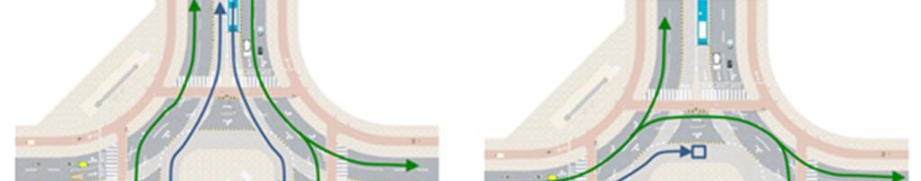


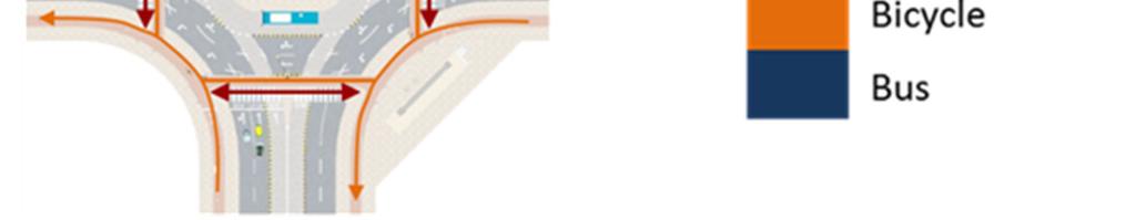
49 The recommended signal phasing plan for this design is as follows. Page 47


50 12. BRT WITH EXPRESS LANE SERVICES The use of express or overtaking lanes is a common feature used for increasing capacity on BRT systems. As some buses can by-pass some stations, the overall throughput of the system can increase considerably beyond what is possible with single-lane operations. In terms of safety, overtaking lanes introduce a new type of conflict that did not exist in the case of single lane operations conflicts between buses. There are several types of conflicts, depending on the overall layout of the station, its number of sub-stops, and the permitted bus merging movements. However, all these crash types have one thing in common they involve buses leaving the station, entering the express lane, and colliding with buses in that lane. The risk of the crash occurring, and particularly its severity, increases with the speed differential between the two buses. The most serious type of crash involves a local bus leaving the station and colliding with an express bus travelling at high speed in the overtaking lane. Figure 2: Crash type involving a collision between a local bus leaving the station and an express bus travelling through A less serious type of crash involves a conflict between a bus leaving the station and another bus attempting to dock at the same time. Figure 1: Side swipe between buses at station This second type of crash usually occurs at a much lower speed, and as a result, it less serious, rarely resulting in injuries and mostly resulting in damage to the buses. It is important to establish clear priority rules around stations. Buses in the left (express) lane should always have the priority, and buses in the right (docking) lane should always yield to them. This should be enforced through driver training and clear signalisation, as shown in the design template. In addition, speed reductions for express buses can help mitigate this crash risk. Unlike the previous templates, this design uses a road of more than 38 meters. This is necessary in order to accommodate all the regular continuous elements of the road, and include one additional continuous element, namely the express lane. Express service BRTs are only viable on roads that are wide enough to accommodate this additional requirement. Page 48

51 Recommended Design Template 9: BRT with express lanes To lower the risk of crashes between local and express buses, we recommend reducing speeds in the overtaking lane to 30 kmph. This will give bus drivers more time to react, will shorten the stopping distance for buses, and will lower the severity of crashes if they do occur. The place where the overtaking lane ends is where the most dangerous conflicts between buses can occur. Such collisions are usually at high speeds, and can result in serious injuries. This is one of the most severe crash types between BRT vehicles reported on the TransMilenio system in Bogota. Buses in the express lanes should always have the right of way over buses in the local lanes. This is reinforced by the yield sign on the pavement ofthelocalbuslane. 49
52 13. BRT TERMINALS Integrated terminals, featuring cross-platform transfers between different trunk and feeder routes, are the safest transfer options for passengers. The recommended layout is a single platform with trunk lines stopping on one side and feeder lines docking on the opposite side. A single platform configuration eliminates any incentive for passengers to cut across bus lanes when transferring between lines. The main safety risk to consider is the access point to the terminal for buses. It is important to avoid bottlenecks and to clearly separate different directions of traffic. TransMilenio recorded a fatal crash occurrence at the Portal de Usme terminal when a trunk line and a feeder line collided head-on at the entrance to the terminal, injuring several passengers and killing one. The safest option would be grade separated access for different buses via overpasses or underpasses, but this would only be a good option for a terminal situated at the urban periphery. In a denser urban area, bus conflicts should be addressed by signalizing the access points to the terminal. Depending on the location of the terminal and the route structure, the biggest pedestrian flows might be transfers between bus routes, in which case it becomes important to design access to the different platforms, or access to and from the terminal, in which case the design of the pedestrian access point becomes crucial. As a general rule, pedestrians and buses should never cross at-grade inside a terminal, since this can easily become a black spot for pedestrian crashes. It is also important to provide sufficient platform width to accommodate the expected volumes of passengers. If the platforms become overcrowded, there is a risk that passengers will end up walking in the bus lanes - particularly on the side of the terminal with low platforms. If a large number of passengers arrive from outside the terminal, then it should be considered to also create grade separated access for pedestrians, via an overpass or an underpass. This type of solution should always be context specific, since grade separation may not always work and pedestrians will rarely use bridges or underpasses if the street to be crossed is not very busy or if the pedestrian infrastructure is not clean, secure and well maintained. Page 50

53 Recommended Design Template 10: BRT terminal Here, the feeder buses dock on the right side of the terminal station, while the BRT buses dock on the left side. Thus, commuters do not have to leave the station building in order to transfer from one type of service to the other. Since there is a level difference between the feeder bus lane and the BRT bus lane, level boarding is possible without needing a step or slope within the station. 51
54 14. IMPACT OF THESE RECOMMENDATIONS ON MIXED TRAFFIC CAPACITY BRT and road capacity A BRT carries multiple times more people per lane than mixed traffic lanes. Yet, the negative impact that BRT has on vehicular capacity is often cited as a criticism against BRT. Opponents of BRT argue that the congestion faced by all other traffic completely offsets any benefit of time saved for BRT commuters, even though, in terms of numbers, the BRT lanes carry more people than the mixed traffic lanes. This has become a deal breaker for some BRTs in India, notably the New Delhi BRT. Since a BRT is typically built along existing roads, some impact on mixed traffic capacity is unavoidable. However, evidence from past BRT systems indicates that conditions in the mixed traffic lanes rarely reach the worst-case scenarios suggested by some critics. Table 1: Mixed traffic volumes on the Macrobus BRT corridor in Guadalajara Date Total traffic (% change from 08) (pre-brt) Vehicles/lane (% change from 08) 2009 (post-brt) 3213 (-11%) 803 (+78%) 2010 (post-brt) 2102 (-42 %) 525 (+17%) The capacity for mixed traffic on the Macrobus BRT corridor in Guadalajara, Mexico reduced from 8 lanes to 4 lanes after the BRT was implemented in March Traffic counts from June 2009 show that overall traffic volumes decreased slightly, but the number of vehicles per lane increased by 78%, to the point where the mixed traffic lanes were operating at or near capacity during the peak hour. However, one year later, traffic volumes had decreased further, to the point where the number of vehicles per lane was within 17% of what it had been before, even though the number of mixed traffic lanes was cut in half. Other BRTs have had a similar 5 Weekday PM peak hour traffic counts, provided by E.P.S. Guadalajara and CTS-EMBARQ Mexico. impact on traffic. After the implementation of the Istanbul BRT in Turkey, for example, annualized average daily traffic (AADT) volumes for private cars on the corridor decreased from 166,425 to 142,217, a 15% reduction. 6 Overall, the data indicates that drivers generally tend to adapt to the presence of the BRT, by either switching routes or switching modes, so that traffic volumes eventually adapt to the new conditions. There is an important caveat to consider here. Guadalajara, as most cities in the Americas, has a dense street network, with average block lengths of 50 to 170 meters. With a street grid this dense, it is not difficult to reroute traffic on one or more parallel streets to the BRT corridor. Indian cities, on the other hand, often tend to have much sparser street networks. Delhi, for example, has average block lengths of 800 to 1900 meters in the area around the Delhi BRT. This is ten times as long, on average, as the typical city blocks of a city in the Americas. Indian cities have 6 Source: EMBARQ Turkey Page 52

55 considerably lower motorisation rates than the US or Europe, but already face significant congestion, and the sparse street networks in India are a major contributing factor to the problem. On the one hand, this suggests that if a BRT is implemented in an Indian city on a street that is already operating near capacity, there are few options for rerouting that traffic on other streets. On the other hand, the low vehicle capacity offered by the sparse street networks in Indian cities is a strong argument in favour of promoting high passenger capacity modes, such as BRT. It is important to note in this context, that the implementation of a BRT often reduces vehicle throughput on a street (Table 1), but always increases passenger throughput (Figure 4). We estimate that the Macrobus corridor in Guadalajara carried 69% more passengers during the peak hour in 42% fewer vehicles after BRT was implemented (Table 1 and Figure 4). On a more detailed level, decisions regarding intersection geometry and signal phasing can also impact mixed traffic capacity on BRT corridors. Figure 3: Comparison of number of through northsouth streets in 4km2 in four cities around the world The development of the BRT results in reengineering of the road, which may correct previous impediments that were affecting traffic flow. Further, the BRT restricts cross movement to an extent, which can also help in improving throughput capacity. Finally, the BRT takes slow-moving and frequentlystopping buses out of the traffic mix. This also helps to create a smoother traffic flow. Before BRT After BRT Peak hour passenger throughput Figure 4: Passenger throughput on the Macrobus corridor in Guadalajara, before and after BRT implementation However, a poorly designed BRT creates unnecessary bottlenecks that reduce traffic capacity. This is especially true at intersections, where poor traffic signal management further aggravates the situation. Page 53
Road Safety and Bus Rapid Transit
 Road Safety and Bus Rapid Transit UNESCAP Regional Expert Group Meeting on Sustainable & Inclusive Transport Development & Second Asia BRTS Conference 2014 30 September, 2014 Ahmedabad, Gujara Binoy Mascarenhas
Footpath design. A guide to creating footpaths that are safe, comfortable, and easy to use
 Footpath design A guide to creating footpaths that are safe, comfortable, and easy to use November 2013 Contents Introduction / 1 Zoning system / 2 Width / 4 Height / 5 Surface / 5 Footpath elements /
Active Transportation Facility Glossary
 Active Transportation Facility Glossary This document defines different active transportation facilities and suggests appropriate corridor types. Click on a facility type to jump to its definition. Bike
Cycle Track Design Best Practices Cycle Track Sections
 Design Best Practices Sections It is along street segments where the separation and protection methods of cycle tracks offer more comfort than conventional bicycle lanes, and are more attractive to a wide
Roadways. Roadways III.
 Introduction 97 Roadway Design Principles 98 Safe Speeds 99 Optimizing of Street Space 00 Minimum Lane Widths in the City of Boston 02 Design Features that Reduce Operating Speeds 05 Travel Lanes Transit
CURBSIDE ACTIVITY DESIGN
 5 CURBSIDE ACTIVITY DESIGN This chapter provides design guidance for separated bike lanes adjacent to curbside activities including parking, loading and bus stops. Typical configurations are presented
Appendix C. TRAFFIC CALMING PROGRAM TOOLBOX
 Appendix C. TRAFFIC CALMING PROGRAM TOOLBOX PHASE I...2 Do Not Enter Sign...3 One-Way Sign...4 Turn Prohibition...5 Pavement Markings...6 Speed Monitoring Trailer...7 Neighborhood Speed Watch...8 Police
City of Elizabeth City Neighborhood Traffic Calming Policy and Guidelines
 City of Elizabeth City Neighborhood Traffic Calming Policy and Guidelines I. Purpose: The City of Elizabeth City is committed to ensure the overall safety and livability of residential neighborhoods. One
TRAFFIC CALMING GUIDE FOR TORONTO CITY OF TORONTO TRANSPORTATION SERVICES DIVISION
 TRAFFIC CALMING GUIDE FOR TORONTO CITY OF TORONTO TRANSPORTATION SERVICES DIVISION CITY OF TORONTO TRANSPORTATION SERVICES DIVISION 2016 TRAFFIC CALMING GUIDE FOR TORONTO TABLE OF CONTENTS Introduction
Simulation Analysis of Intersection Treatments for Cycle Tracks
 Abstract Simulation Analysis of Intersection Treatments for Cycle Tracks The increased use of cycle tracks also known as protected bike lanes has led to investigations of how to accommodate them at intersections.
10.0 CURB EXTENSIONS GUIDELINE
 10.0 CURB EXTENSIONS GUIDELINE Road Engineering Design Guidelines Version 1.0 March 2017 City of Toronto, Transportation Services City of Toronto Page 0 Background In early 2014, Transportation Services
VRU Safety & Traffic Calming Measures in Urban & Rural Areas
 VRU Safety & Traffic Calming Measures in Urban & Rural Areas 2 What is Traffic Calming? Road engineering approaches aimed at bringing the design of the road in accordance with the desired speeds of the
MEMORANDUM. Charlotte Fleetwood, Transportation Planner
 MEMORANDUM Date: Updated August 22, 2017 To: Organization: Charlotte Fleetwood, Transportation Planner Boston Transportation Department From: Jason DeGray, P.E., PTOE, Regional Director of Engineering
Road Markings. Lecture Notes in Transportation Systems Engineering. Prof. Tom V. Mathew
 Road Markings Lecture Notes in Transportation Systems Engineering Prof. Tom V. Mathew 1 Overview The essential purpose of road markings is to guide and control traffic on a highway. They supplement the
2.0 LANE WIDTHS GUIDELINE
 2.0 LANE WIDTHS GUIDELINE Road Engineering Design Guidelines Version 2.0.1 May 2018 City of Toronto, Transportation Services City of Toronto Page 0 Background In early 2014, Transportation Services initiated
guide to a phased approach TRIPP
 complete street development guide to a phased approach TRIPP development phases Existing 00 months 00 crores/km Phase 0 months 0 crores/km Phase 09 months 0 to 08 crores/km Phase months 07 to crores/km
Broad Street Bicycle Boulevard Design Guidelines
 Broad Street Bicycle Boulevard Design Guidelines Building from the strategies introduced in the 2013 Bicycle Transportation Plan and community input received thus far, City Transportation Staff have identified
Road Markings. Lecture Notes in Transportation Systems Engineering. Prof. Tom V. Mathew. 1 Overview 1. 2 Classification 2
 Road Markings Lecture Notes in Transportation Systems Engineering Prof. Tom V. Mathew Contents 1 Overview 1 2 Classification 2 3 Longitudinal markings 2 3.1 Center line.....................................
$ 12" $#&%$ 86.) *1! *1 /3 )00, , (1* Neighborhood Traffic Calming Part 3 Solutions Bradley William Yarger, P.E.
 *1! *1 /3 )00, , (1* Neighborhood Traffic Calming Part 3 Solutions Bradley William Yarger, P.E.") $ 12" $#&%$ 86.)3+5+2 714 *1! *1 /3 )00,12 3.+ -0127 1, (1* Neighborhood Traffic Calming Part 3 Solutions by Bradley William Yarger, P.E. It is extremely tempting to jump to this step of the process thinking
$ 12" $#&%$ 86.)3+5+2 714 *1! *1 /3 )00,12 3.+ -0127 1, (1* Neighborhood Traffic Calming Part 3 Solutions by Bradley William Yarger, P.E. It is extremely tempting to jump to this step of the process thinking
4. Guided Bus Explained
 4. Guided Bus Explained Contents 1 INTRODUCTION... 2 Structure of this report... 2 2 KERB GUIDED BUS... 3 Overview... 3 Kerb guidance... 3 Figures Figure 2.1 Figure 2.2 Figure 2.3 Figure 2.4 Figure 2.5
5. RUNNINGWAY GUIDELINES
 5. RUNNINGWAY GUIDELINES These guidelines should be considered collectively when making runningway decisions. A runningway is the linear component of the transit system that forms the right-of-way reserved
Figure 3B-1. Examples of Two-Lane, Two-Way Marking Applications
 Figure 3B-1. Examples of Two-Lane, Two-Way Marking Applications A - Typical two-lane, two-way marking with passing permitted in both directions B - Typical two-lane, two-way marking with no-passing zones
MUTCD Part 6G: Type of Temporary Traffic Control Zone Activities
 MUTCD Part 6G: Type of Temporary Traffic Control Zone Activities 6G.01 Typical Applications Each temporary traffic control (TTC) zone is different. Many variables, such as location of work, highway type,
UNIT V 1. What are the traffic management measures? [N/D-13] 2. What is Transportation System Management (TSM)? [N/D-14]
![UNIT V 1. What are the traffic management measures? [N/D-13] 2. What is Transportation System Management (TSM)? [N/D-14]](/thumbs/87/95571671.jpg "UNIT V 1. What are the traffic management measures? [N/D-13] 2. What is Transportation System Management (TSM)? [N/D-14]") UNIT V 1. What are the traffic management measures? [N/D-13] Some of the well-known traffic management measures are: a) Restrictions on turning movements b) One - way streets c) Tidal - flow operations
UNIT V 1. What are the traffic management measures? [N/D-13] Some of the well-known traffic management measures are: a) Restrictions on turning movements b) One - way streets c) Tidal - flow operations
INTERSECTIONS AT GRADE INTERSECTIONS
 INTERSECTIONS 1 AT GRADE INTERSECTIONS INTERSECTIONS INTERSECTIONS = INTERRUPTED FACILITIES Definitions and key elements An intersection is defined as an area where two or more roadways join or cross.
PLANNING FOR SUSTAINABLE PEDESTRIAN INFRASTRUCTURE NALIN SINHA INITIATIVE FOR TRANSPORTATION & DEVELOPMENT PROG. (ITD), DELHI
, DELHI") PLANNING FOR SUSTAINABLE PEDESTRIAN INFRASTRUCTURE NALIN SINHA INITIATIVE FOR TRANSPORTATION & DEVELOPMENT PROG. (ITD), DELHI India s Road Network 5 million kms: Total road length 2.6 mn kms: Surfaced
PLANNING FOR SUSTAINABLE PEDESTRIAN INFRASTRUCTURE NALIN SINHA INITIATIVE FOR TRANSPORTATION & DEVELOPMENT PROG. (ITD), DELHI India s Road Network 5 million kms: Total road length 2.6 mn kms: Surfaced
2. Context. Existing framework. The context. The challenge. Transport Strategy
 Transport Strategy Providing quality connections Contents 1. Introduction 2. Context 3. Long-term direction 4. Three-year priorities 5. Strategy tree Wellington City Council July 2006 1. Introduction Wellington
EUCLID AVENUE PARKING STUDY CITY OF SYRACUSE, ONONDAGA COUNTY, NEW YORK
 EUCLID AVENUE PARKING STUDY CITY OF SYRACUSE, ONONDAGA COUNTY, NEW YORK CITY OF SYRACUSE DEPARTMENT OF PUBLIC WORKS 1200 CANAL STREET EXTENSION SYRACUSE, NEW YORK 13210 DRAFT REPORT DATE: November 13,
Economic and Social Council
 UNITED NATIONS E Economic and Social Council Distr. GENERAL 20 December 2006 ENGLISH Original: ENGLISH and FRENCH ECONOMIC COMMISSION FOR EUROPE INLAND TRANSPORT COMMITTEE Working Party on Road Traffic
Appendix T CCMP TRAIL TRAFFIC & TRANSPORTATION DESIGN STANDARD
 Appendix T CCMP 3.3.4 TRAIL TRAFFIC & TRANSPORTATION DESIGN STANDARD 3.3.4 Trail Traffic and Transportation Design Multi-use trails have certain design standards, which vary depending on the agency that
Bus Rapid Transit (BRT) sets a new global trend in public transportation
 sets a new global trend in public transportation") 01 Transportation Planning 7 International comparative study of Seoul BRT system Ko, Joonho Summary The ridership of the bus rapid transit system in Seoul is the fifth highest among 162 cities worldwide,
01 Transportation Planning 7 International comparative study of Seoul BRT system Ko, Joonho Summary The ridership of the bus rapid transit system in Seoul is the fifth highest among 162 cities worldwide,
IMPLEMENTATION. PEDESTRIAN USERS (Continued /) A: Class 2 Pedestrian / Cycle Ways. Pedestrian and Cycle Ways:
 A: Class 2 Pedestrian / Cycle Ways. Pedestrian and Cycle Ways:") A: Class 2 Pedestrian / Cycle Ways PLAN VIEW Pedestrian and Cycle Ways: Layout and Geometry (Refer to A): Walkways and cycle to be provided adjacent to all Class 2 Roads (these facilities should always
A: Class 2 Pedestrian / Cycle Ways PLAN VIEW Pedestrian and Cycle Ways: Layout and Geometry (Refer to A): Walkways and cycle to be provided adjacent to all Class 2 Roads (these facilities should always
IMPLEMENTATION. PEDESTRIAN USERS (Continued /) Building Frontages: A: Stair Applications. Geometry (Accessed from the Sidewalk) Refer to A:
 Building Frontages: A: Stair Applications. Geometry (Accessed from the Sidewalk) Refer to A:") A: Stair Applications Building Frontages: Geometry (Accessed from the Sidewalk) Refer to A: Ramps should be provided for disabled users at 1:12 (8.3%) gradient. Ramp rises should be stepped at 400mm intervals.
A: Stair Applications Building Frontages: Geometry (Accessed from the Sidewalk) Refer to A: Ramps should be provided for disabled users at 1:12 (8.3%) gradient. Ramp rises should be stepped at 400mm intervals.
AUTOMATED AND ZERO EMISSION VEHICLES HOW THEY MIGHT RESHAPE OUR STREETS
 AUTOMATED AND ZERO EMISSION VEHICLES HOW THEY MIGHT RESHAPE OUR STREETS BACKGROUND: This study is a collaboration between Urban Circus (Visualisation) and Ethos Urban (Urban Design) Ideas were workshopped
Urban Street Design and Development
 Urban Street Design and Development Ashok Bhattacharjee, Advisor, Clean Air and Sustainable Mobility, Centre for Science and Environment CSE Workshop on Safe Access and Parking - Lytton Hotel, Kolkata
Planning Guidance in the 2012 AASHTO Bike Guide
 Planning Guidance in the 2012 AASHTO Bike Guide Presentation by: RJ Eldridge Peter Lagerwey August 22, 2012 WEBINAR 2: PLANNING GUIDANCE IN THE 2012 AASHTO BIKE GUIDE Today s Webinar Significant Updates
CHECKLIST 2: PRELIMINARY DESIGN STAGE AUDIT
 CHECKLIST 2: PRELIMINARY DESIGN STAGE AUDIT 2.1 General topics 2.1.1 Changes since previous audit Do the conditions for which the scheme was originally designed still apply? (for example, no changes to
Sustainable Transport Saves Lives
 Sustainable Transport Saves Lives Ashwin Prabhu Principle Associate EMBARQ India International Conference on Green Buildings CII & IGBC 25 th October, 2013 Background - Road & Traffic Incidents Number
CITY OF WEST KELOWNA COUNCIL POLICY MANUAL
 CITY OF WEST KELOWNA COUNCIL POLICY MANUAL Page 1 of 7 DEPARTMENT: Engineering Services SUBJECT: Traffic Calming Policy (Revised June 6, 2017) Policy Statement: The provision of traffic calming measures
General Design Factors
 Chapter 3: 3-1.0 Introduction General Design Factors Mn/DOT s goals include encouraging and accommodating safe bicycling. From a design perspective, these goals are achieved by first having an understanding
The Safe System Approach
 There are very few areas of public discussion and sentiment which generate as much consensus as road safety. Everyone wants safer roads for all users, and road safety is a key priority for governments,
Chapter 2: Standards for Access, Non-Motorized, and Transit
 Standards for Access, Non-Motorized, and Transit Chapter 2: Standards for Access, Non-Motorized, and Transit The Washtenaw County Access Management Plan was developed based on the analysis of existing
Classification Criteria
 SCHEDULE D TO RECOMMENDED OFFICIAL PLAN AMENDMENT NO. 40 SCHEDULE C-4 Road Criteria Criteria Traffic Service Objective Land Service/Access Typical Daily Traffic Volume Flow characteristics Travel Speed
ROUNDABOUTS/TRAFFIC CIRCLES
 GENERAL 1. Description This standard identifies minimum requirements that shall be met for Roundabouts and Neighborhood Traffic Circles in the design and construction of elements for Arlington County Horizontal
Appendix A: Crosswalk Policy
 Appendix A: Crosswalk Policy Appendix A: Crosswalk Policy Introduction This citywide Crosswalk Policy is aimed at improving pedestrian safety and enhancing pedestrian mobility by providing a framework
Public Works Committee Meeting Richard E. Mastrangelo Council Chamber November 20, 2017
 Public Works Committee Meeting Richard E. Mastrangelo Council Chamber November 20, 2017 Purpose of Meeting Why are we here? Project Recap/Updates Project Limits/Segments Road Diet Concept Lessons Learned
(HIGHWAY GEOMETRIC DESIGN -1)
") LECTURE HOUR-19 TE-1(10CV56) UNIT-3 (HIGHWAY GEOMETRIC DESIGN -1) Width of carriage way: Width of the carriage way or the width of the pavement depends on the width of the traffic lane and number of lanes.
LECTURE HOUR-19 TE-1(10CV56) UNIT-3 (HIGHWAY GEOMETRIC DESIGN -1) Width of carriage way: Width of the carriage way or the width of the pavement depends on the width of the traffic lane and number of lanes.
Mission-Geneva Transportation Study Community Workshop 2 July 8, 2006
 Community Workshop 2 July 8, 2006 Small Group Workbook 1 Basic Improvements on Mission Street Streetscape. Pedestrian-scale lighting; landscaping; community art on utility boxes; more (possibly unique)
The Corporation of the City of Sarnia. School Crossing Guard Warrant Policy
 The Corporation of the City of Sarnia School Crossing Guard Warrant Policy Table of Contents Overview And Description... 2 Role of the School Crossing Guard... 2 Definition of a Designated School Crossing...
Coquitlam Cross-town Bike Route Improving Bicycle Facilities in a Mature Suburban Environment
 Coquitlam Cross-town Bike Route Improving Bicycle Facilities in a Mature Suburban Environment Sarah Rocchi, Vice-President, Projects, Opus International Consultants (Main Presenter) Catherine Mohoruk,
Cycling and risk. Cycle facilities and risk management
 Cycling and risk Cycle facilities and risk management Failure to recognize possibilities is the most dangerous and common mistake one can make. Mae Jemison, astronaut 6/11/2010 York Regional Council Cycling
APPENDIX A: Complete Streets Checklist DRAFT NOVEMBER 2016
 APPENDIX A: Complete Streets Checklist DRAFT NOVEMBER 2016 Complete Streets Checklist MetroPlan Orlando s Complete Streets Checklist is an internal planning tool for staff to further implementation of
RIGHT TURNS AT INTERSECTIONS: ARE THERE ALTERNATIVES?
 RIGHT TURNS AT INTERSECTIONS: ARE THERE ALTERNATIVES? R.C. Pyke, J.D. Sampson and K.G. Schmid Stewart Scott International, P O Box 784506, Sandton, 2146 TTT Africa, P.O.Box 109, Sunninghill, G.D.P.T.R.W,
Traditional Public Transport Priority. Priority/Traffic Management? What is Integrated Public Transport Priority/Traffic management? Why? How?
 Integrated Public Transport Priority & Traffic Management Sam Zimmerman What is Integrated Public Transport Priority/Traffic management? Why? How? Integrated Public Transport Priority/Traffic Management?
complete streets design and construction standards public primer City of Edmonton
 complete streets design and construction standards public primer City of Edmonton introduction Complete Streets are streets for everyone: people who walk, wheel, bike, take transit, or drive. They are
Mission Bay Loop (MBL) Public Meeting
 Public Meeting") Mission Bay Loop (MBL) Public Meeting La Scuola Internazionale di San Francisco, November 18, 2014 Frequently Asked Questions 1. When would construction have to start before the SFMTA loses TIGER funds?
Mission Bay Loop (MBL) Public Meeting La Scuola Internazionale di San Francisco, November 18, 2014 Frequently Asked Questions 1. When would construction have to start before the SFMTA loses TIGER funds?
Evaluation and Changes to Pedestrian Priority Phase Signal (Scramble Crossing) at Bay Street and Bloor Street
 at Bay Street and Bloor Street") PW2.2 STAFF REPORT ACTION REQUIRED Evaluation and Changes to Pedestrian Priority Phase Signal (Scramble Crossing) at Bay Street and Bloor Street Date: February 12, 2015 To: From: Public Works and Infrastructure
PW2.2 STAFF REPORT ACTION REQUIRED Evaluation and Changes to Pedestrian Priority Phase Signal (Scramble Crossing) at Bay Street and Bloor Street Date: February 12, 2015 To: From: Public Works and Infrastructure
Off-road Trails. Guidance
 Off-road Trails Off-road trails are shared use paths located on an independent alignment that provide two-way travel for people walking, bicycling, and other non-motorized users. Trails specifically along
TEAM: ROAD: SECTION: K K Nagar Walkability Survey 19 th June 2013
 K K Nagar Walkability Survey 19 th June 2013 TEAM: ROAD: SECTION: Length of surveyor s foot in cms. (any one): (this surveyor will measure distances required in Table II and points 2.c and 4.a in Table
CHAPTER 1 STANDARD PRACTICES
 CHAPTER 1 STANDARD PRACTICES OBJECTIVES 1) Functions and Limitations 2) Standardization of Application 3) Materials 4) Colors 5) Widths and Patterns of Longitudinal Pavement Marking Lines 6) General Principles
Resident s Toolkit Traffic Control Device Local Area Traffic Management
 Resident s Toolkit Traffic Control Device Local Area Traffic Management This booklet contains information on traffic control devices commonly used in South Australia. A traffic control device is a sign,
CITY OF SAINT JOHN TRAFFIC CALMING POLICY
 CITY OF SAINT JOHN TRAFFIC CALMING POLICY VERSION: 1.0 April 10, 2012 Pedestrians, Cyclists and Motorists Sharing Street Spaces CONTENTS INTRODUCTION... 3 POLICY GOAL... 3 POLICY OBJECTIVES... 3 GUIDING
Appendix A Type of Traffic Calming Measures Engineering Solutions
 Appendix A Type of Traffic Calming Measures Engineering Solutions PHYSICAL MEASURES Central Hatching The major consideration of this feature is that, these markings can only be laid down the centre of
Physical Implications of Complete Streets Policies
 Presentation Overview Physical Implications of Complete Norm Cox, ASLA, LLA Landscape Architect Ann Arbor, Michigan, 10:45 to Noon What Are Complete Streets? What Matters to Bicyclists and Pedestrians
NMT SAFE STUDY APPROACH
 24 May 2017 ADVOCATING THE NON MOTORISED TRANSPORT AGENDA CONTENT Content NMT road safety study approach NMT road safety study process NMT SAFE STUDY APPROACH THE NEED FOR NMT SAFETY STUDIES Is there is
M-58 HIGHWAY ACCESS MANAGEMENT STUDY Mullen Road to Bel-Ray Boulevard. Prepared for CITY OF BELTON. May 2016
 M-58 HIGHWAY ACCESS MANAGEMENT STUDY Prepared for CITY OF BELTON By May 2016 Introduction Missouri State Highway 58 (M-58 Highway) is a major commercial corridor in the City of Belton. As development has
Document 2 - City of Ottawa Pedestrian Crossover (PXO) Program
 Program") 40 Document 2 - City of Ottawa Pedestrian Crossover (PXO) Program OVERVIEW The City of Ottawa Pedestrian Crossover (PXO) Program provides the basis for PXO implementation in Ottawa. The program s processes
40 Document 2 - City of Ottawa Pedestrian Crossover (PXO) Program OVERVIEW The City of Ottawa Pedestrian Crossover (PXO) Program provides the basis for PXO implementation in Ottawa. The program s processes
Agenda. Overview PRINCE GEORGE S PLAZA METRO AREA PEDESTRIAN PLAN
 PRINCE GEORGE S PLAZA METRO AREA PEDESTRIAN PLAN May 28, 2008 Agenda Welcome and introductions Project overview and issue identification Planning context and strengths Design challenges and initial recommendations
700 Multi-Modal Considerations
 700 Multi-Modal Considerations Table of Contents 701 Railroads... 7-1 701.1 Background... 7-1 701.2 Crossing At-Grade... 7-1 701.2.1 General... 7-1 701.2.2 Railroad Parallel to Highway... 7-1 701.3 Lateral
TRAFFIC CALMING PLANNER S PORTFOLIO
 TRAFFIC CALMING PLANNER S PORTFOLIO ISSUE 8 January 2017 PLANNER S PORTFOLIO TRAFFIC CALMING 1 OVERVIEW 2 3 4 ENGINEERED TRAFFIC CALMING MEASURES SIGNS AND PAVEMENT MARKINGS EMERGENCY RESPONSE DELAYS 5
Why Zone In on Speed Reduction?
 Learn it. Do it. Live it! SPEED REDUCTION IN THE ZONE Why Zone In on Speed Reduction? Speeding is a serious issue that plays a major role in the risk of serious injury and pedestrian fatality in a crash.
INTRODUCTION THOROUGHFARE SYSTEM CLASSIFICATIONS
 INTRODUCTION The thoroughfare plan will assist public officials in the development of a specialized system for efficient and safe movement of vehicular traffic while minimizing potential conflicts with
City of Wayzata Comprehensive Plan 2030 Transportation Chapter: Appendix A
 A1. Functional Classification Table A-1 illustrates the Metropolitan Council s detailed criteria established for the functional classification of roadways within the Twin Cities Metropolitan Area. Table
E4 Cycle Route Exeter University to Redhayes Bridge. - Recommendations from Exeter Cycling Campaign
 E4 Cycle Route Exeter University to Redhayes Bridge - Recommendations from Exeter Cycling Campaign 1.0 Introduction Exeter Cycling Campaign has prepared this report to provide recommendations for Devon
Complete Street Analysis of a Road Diet: Orange Grove Boulevard, Pasadena, CA
 Complete Street Analysis of a Road Diet: Orange Grove Boulevard, Pasadena, CA Aaron Elias, Bill Cisco Abstract As part of evaluating the feasibility of a road diet on Orange Grove Boulevard in Pasadena,
Chapter 5: Crossing the Street
 Chapter 5: Crossing the Street Whether walking or bicycling, a student s journey to school will more than likely require crossing one or more streets. Per the Safe Routes to School Guide, maintained by
Bikeway action plan. Bicycle Friendly Community Workshop March 5, 2007 Rochester, MN
 Bikeway action plan Summary The was held on March 5, 2007 at the Rochester Mayo Civic Center. The workshop was hosted by Rochester-Olmsted County Planning Department in collaboration with the League of
A Residential Guide to Neighborhood Speed Enforcement
 A Residential Guide to Neighborhood Speed Enforcement City of Delaware, Ohio A Residential Guide to Neighborhood Speed Enforcement Introduction: The perception of speeding on local streets is probably
Cyclists at road narrowings
 Traffic Advisory Leaflet 1/97 February 1997 Cyclists at road narrowings Introduction Traffic calmed streets can offer a more attractive environment for cycling, by reducing motor vehicles speeds to a level
1. Introduction. 2. Survey Method. Volume 6 Issue 5, May Licensed Under Creative Commons Attribution CC BY
 A Study on Performance of an Urban Arterial Corridor Guggilla Raju 1, Rontala Ashwini 2 1 Assistant Professor, Department of Civil Engineering, GCET 2 Assistant Professor, Department of Civil Engineering,
DEFINITIONS Activity Area - Advance Warning Area Advance Warning Sign Spacing Advisory Speed Approach Sight Distance Attended Work Space
 DEFINITIONS Activity Area - that part of a TTC zone activity area where the work actually takes place. It consists of the work space, traffic space and one or more buffer spaces. Advance Warning Area -
Introduction Methodology Study area and data collection Results and recommendation Conclusion References
 Introduction Methodology Study area and data collection Results and recommendation Conclusion References It is formal procedure for assessing accident potential and safety performance in the provision
Memorandum. Exhibit 60 SSDP To: Jenny Bailey, Senior Planner. From: Bill Schultheiss, P.E. (WA. P.E. #46108) Date: June 20, 2017
 Date: June 20, 2017") Memorandum To: Jenny Bailey, Senior Planner From: Bill Schultheiss, P.E. (WA. P.E. #46108) Date: June 20, 2017 Re: East Lake Sammamish Trail, Segment 2B Review King County has asked Toole Design Group
Memorandum To: Jenny Bailey, Senior Planner From: Bill Schultheiss, P.E. (WA. P.E. #46108) Date: June 20, 2017 Re: East Lake Sammamish Trail, Segment 2B Review King County has asked Toole Design Group
Access Location, Spacing, Turn Lanes, and Medians
 Design Manual Chapter 5 - Roadway Design 5L - Access Management 5L-3 Access Location, Spacing, Turn Lanes, and Medians This section addresses access location, spacing, turn lane and median needs, including
AUTOMATED AND ZERO EMISSION VEHICLES HOW THEY MIGHT RESHAPE OUR STREETS
 AUTOMATED AND ZERO EMISSION VEHICLES HOW THEY MIGHT RESHAPE OUR STREETS STURT ST BALLARAT WATERGARDENS TAYLORS LAKES SIMPSON ST YARRAVILLE CHAPEL ST SOUTH YARRA RINGWOOD STATION MONASH FREEWAY SA NSW VIC
PEDESTRIAN ACTION PLAN
 ATTACHMENT 2 CITY OF SANTA MONICA PEDESTRIAN ACTION PLAN CITY OF SANTA MONICA PEDESTRIAN ACTION PLAN This page intentionally left blank EXECUTIVE SUMMARY CHAPTER 1 EXECUTIVE SUMMARY Setting the Stage
1 st and 2 nd Street Couplet FAQ s
 1 st and 2 nd Street Couplet FAQ s Q. Will the proposed roundabout at Flume/2nd/1 st Streets affect access to businesses nearby?... 2 Q. What if the project isn t received well by the community after construction?...
METHODOLOGY. Signalized Intersection Average Control Delay (sec/veh)
") Chapter 5 Traffic Analysis 5.1 SUMMARY US /West 6 th Street assumes a unique role in the Lawrence Douglas County transportation system. This principal arterial street currently conveys commuter traffic
Chapter 5 Traffic Analysis 5.1 SUMMARY US /West 6 th Street assumes a unique role in the Lawrence Douglas County transportation system. This principal arterial street currently conveys commuter traffic
Figure 5-1 Complete Street Zones. Roadside. May include frontage, pedestrian throughway, furnishings and curbside areas.
 Design Guidelines 5 The design guidelines presented in this section provide descriptions related to the form and function of the four Complete Streets zones: roadside, parking, roadways and lanes, median,
On Road Bikeways Part 1: Bicycle Lane Design
 On Road Bikeways Part 1: Bicycle Lane Design Presentation by: Nick Jackson Bill Schultheiss, P.E. September 04, 2012 FOLLOW THE CONVERSATION ON TWITTER Toole Design Group is live tweeting this webinar
At each type of conflict location, the risk is affected by certain parameters:
 TN001 April 2016 The separated cycleway options tool (SCOT) was developed to partially address some of the gaps identified in Stage 1 of the Cycling Network Guidance project relating to separated cycleways.
OCTOBER 3, 2016 DRAFT URBAN CYCLING DESIGN GUIDELINES COMPREHENSIVE BICYCLE PLAN FOR PUNE
 OCTOBER 3, 2016 DRAFT URBAN CYCLING DESIGN GUIDELINES COMPREHENSIVE BICYCLE PLAN FOR PUNE Index 1. Introduction... 4 2. Cycling-inclusive planning and design... 5 2.1 Introduction... 5 2.2 Demotorization
Tonight is for you. Learn everything you can. Share all your ideas.
 Strathcona Neighbourhood Renewal Draft Concept Design Tonight is for you. Learn everything you can. Share all your ideas. What is Neighbourhood Renewal? Creating a design with you for your neighbourhood.
Guidance. ATTACHMENT F: Draft Additional Pages for Bicycle Facility Design Toolkit Separated Bike Lanes: Two-Way to One-Way Transitions
 ATTACHMENT F: Draft Additional Pages for Bicycle Facility Design Toolkit Separated Bike Lanes: Two-Way to One-Way Transitions This treatment provides a transition from two-way separated bike lanes to one-way
CITY OF SARATOGA SPRINGS PEDESTRIAN CROSSING TOOLBOX
 CITY OF SARATOGA SPRINGS PEDESTRIAN CROSSING TOOLBOX This toolbox is to be used to guide pedestrian crossing improvements within the City of Saratoga Springs. Details for each crossing type are provided.
Cabinet Member for Highways & Streetscene. Highway Infrastructure Manager
 LONDON BOROUGH OF RICHMOND UPON THAMES DATE: AUGUST 2015 DECISION MAKER: LEAD OFFICER: SUBJECT: WARDS: Cabinet Member for Highways & Streetscene Highway Infrastructure Manager PROPOSED CYCLING IMPROVEMENTS
Part B Design Guidance / Principles _
 Part B Design Guidance / Principles www. landlab.co.nz Queenstown Town Centre Public Realm Design Guidelines Version 7 14 June 2018 Page 006 B1 Design Guidance & Best Practice The Queenstown Town Centre
PESHAWAR Bus Rapid TRANSIT. By Engr. Haroon Rashid Ph. D Scholar, MS in Transportation Planning and B.Sc Civil Engineering
 PESHAWAR Bus Rapid TRANSIT By Engr. Haroon Rashid Ph. D Scholar, MS in Transportation Planning and B.Sc Civil Engineering 1 OUTLINE Aim and Objective What is BRT? Why BRT? BRT as High Performance Transit
ACTIVE TRANSPORTATION
 ACTIVE TRANSPORTATION Mobility 2040 Supported Goals Improve the availability of transportation options for people and goods. Support travel efficiency measures and system enhancements targeted at congestion
Relative safety of alternative intersection designs
 Urban Transport XII: Urban Transport and the Environment in the 21st Century 379 Relative safety of alternative intersection designs L. C. Wadhwa 1 & M. Thomson 2 1 James Cook University Townsville Queensland