Interconnection of Highway-Rail Grade Crossing Warning Systems and Highway Traffic Signals
|
|
|
- Samuel Ray
- 5 years ago
- Views:
Transcription


1 Interconnection of Highway-Rail Grade Crossing Warning Systems and Highway Traffic Signals 1
2 INTRODUCTION Welcome to this seminar on Interconnection of Highway-Rail Grade Crossing Warning Systems and Highway Traffic Signals. Over the past eight years, I have had the opportunity to present this seminar to persons from the Federal Railroad Administration, the Federal Highway Administration, numerous state Departments of Transportation, city, county and state traffic engineering and signal departments as well as many railroads. Obviously, this is a highly specialized topic, one that receives very little attention in terms of available training. However, from the perspective of safety, it requires far more attention than it normally receives. Only when a catastrophic event occurs such as the Fox River Grove crash in October of 1995 does the need for training of this type become apparent. Following the Fox River Grove crash, I was approached by the Oklahoma Department of Transportation in 1996, inquiring if I would have an interest in assisting them with understanding interconnection and preemption. This seminar is the ongoing continuation of that effort. My background includes over 31 years of active involvement in both highway traffic signal and railroad signal application, design and maintenance. This workbook is a compilation of information, drawings, standards, recommended practices and my ideas to assist you in following with the presentation and to provide a future reference as you need it. It has been developed as I have presented seminars and I strive to continually update it to reflect the most current information available. Some sections have been reproduced from the Manual on Uniform Traffic Control Devices which exists in the public domain. Other sections from the AREMA Communication & Signal Manual of Recommended Practice and Institute of Transportation Engineers recommended practice for Preemption of Traffic Signals Near Railroad Grade Crossings are reproduced with permission to be used only for training and education. Use of these sections as work product requires the user to purchase a licensed copy from AREMA or ITE at their web sites listed below. It should also be noted that both publications are living documents which undergo continuing updates and revisions to address changing technology and practice. Therefore, the user should maintain current documents for use and reference. Finally, I depend on you to provide me with feed back to assist in improving the content and presentation of this material. Please take a few minutes after the seminar to complete the comment form for me. If you would like, leave me your contact information if there is a specific thought or comment you want to discuss individually. If you need follow-up information or have a question my staff or I might be able to assist with, you can contact me from the information listed below. Rick Campbell 2
3 INTRODUCTION Additional information from standards and recommended practices used in this seminar may be obtained from the following: MUTCD 2003 Edition Manual Federal Highway Administration AREMA Communication & Signal Manual of Recommended Practices American Railway Engineering and Maintenance-of-Way Association Preemption of Traffic Signals Near Railroad Crossings Institute of Transportation Engineers Rick Campbell President Railroad Controls Limited 7471 Benbrook Parkway Benbrook, TX Voice Phone: Fax Phone: web page: 3
4 Fox River Grove, IL October 25,
5 Workbook Index 7. Advance Preemption Paper Presented to AREMA 16. Highway Traffic Signals Phase Intersection Phase Intersection with Detectors Phase Intersection with Pedestrian Movements Phase Intersection with Detectors and Pedestrian Movements 27. Basic Traffic Signal Timing Phase Intersection Phase Intersection with Detectors Phase Sequence Phase Intersection with Pedestrian Movements Phase Intersection with Detectors and Pedestrian Movements 33. Railroad Crossing Signals 34. MUTCD Part 8A.01 - Introduction Track Crossing 78. Motion Sensor Crossing 81. Constant Warning Time Crossing 84. MUTCD Part 8D.07 - Traffic Control Signals at or Near Highway-Rail Grade Crossings 86. MUTCD Part 8A.01 - Definitions 100.MUTCD Part 4D.02 - Responsibility for Operation and Maintenance 101.MUTCD Part 4D.13 - Preeemption and Priority Control of Traffic Control Signals 103.MUTCD Part 4E.09 - Pedestrian Intervals and Signal Phases 5
6 Index (continued) 105. AREMA Signal Manual, Section (Recommended Functional/Operating Guidelines for Interconnection between Highway Traffic Signals and Highway-Rail Grade Crossing Warning Systems - Revised 2002) 111. AREMA Signal Manual, Section (Recommended Instructions for Determining Warning Time and Calculating Approach Distance for Highway-Rail Grade Crossing Warning Systems - Revised 2002) 115. AREMA Signal Manual, Section (Recommended Vital Circuit Design Guidelines for Highway Traffic Signal Preemption - Extended 2000) Phase Dual Ring Intersection with Pedestrian Movement and Railroad Phase Dual Ring Intersection with Pedestrian Movement and 2 Track Railroad 125. Railroad Preempt Phase Sequence 126. Guide for Determining Time Requirements for Traffic Signal Preemption at Highway-Rail Grade Crossings, MNDOT 128. Instructions for Guide for Determining Time Requirements For Traffic Signal Preemption at Highway-Rail Grade Crossings, MNDOT 137. Guide for Determining Time Requirements for Traffic Signal Preemption at Highway-Rail Grade Crossings, Texas DOT 140. Instructions for Guide for Determining Time Requirements for Traffic Signal Preemption at Highway-Rail Grade Crossings, Texas DOT 156. Vehicle Dynamics for Computing Track Clearance Vehicles Accelerating from a Stopped Position Distance Traveled Over Time from a Stopped Position 158. Basic Preempt Time Line 159. Preempt Time Line - Blank 160. Intersection Geometric Considerations 162. Special Considerations for Advance Preemption Warning Label 169. Presignal Applications at Highway-Rail Grade Crossings 6
7 ADVANCE PREEMPTION PRESENTED TO AREMA 1998 ANNUAL MEETING CHICAGO, ILLINOIS PRESENTED BY RICHARD M. CAMPBELL PRESIDENT RAILROAD CONTROLS LIMITED 500 SOUTH FREEWAY FORT WORTH, TEXAS
8 For years, many Highway Traffic Signals located adjacent to Highway-Rail Grade Crossings with active warning systems have been interconnected. This interconnection is intended to pre-empt the normal operation of the Traffic Signal when a Train approaches the Grade Crossing, so that vehicles stopped on the tracks can receive a Green Signal to get clear of the tracks. The requirement for interconnection and preemption is The application and operation of this interconnection has existed in many forms, and been identified by many different names such as preemption, interconnect, railroad circuit, railroad tie-in, railroad preemption, etc. There were even wide variations in the electrical configuration utilized. In most cases, Railroads and Highway Departments maintained their respective portion of these circuits independently, and often referred to the same functions of the System by completely different names. Each party believed they were doing the right thing. On October 25, 1995, a tragedy occurred in Fox River Grove, Illinois that would forever change the casual approach given to these interconnections. A METRA Commuter Train, operating on the Union Pacific Railroad, struck a school bus at the Algonquin Road Highway-Rail Grade Crossing. The force of the impact sheared the body of the bus from its chassis, and seven students perished. As officials began to collect data and reconstruct events leading up to the crash, a very alarming fact came to light The Railroad Signal Personnel and Traffic Signal Personnel knew and understood the operation of their own systems, but knew virtually nothing about the other portion of the system to which it was connected! They also referred to identical functions using different terminology. This lack of understanding was further demonstrated when most surprisingly, the particular tests performed by each group on their respective portion of the system determined that it was operating as designed! The stage was now set for a Repeat Performance of the Fox River crash! 8
9 For many years, Association of American Railroad representatives understood the need for vital control logic, and attempted to initiate changes. It was common to find wide varieties of electrical parameters utilized, including normally open or normally closed circuits, typically all single break, with varying levels of operational voltages. A number of years ago, the National Committee (which is responsible for determining the standards published in the Manual on Uniform Traffic Control devices), adopted a standard requiring a normally closed circuit between the Traffic Signal Controller and the Grade Crossing Warning System. However, little else was done relative to the interconnect circuit itself. The National Committee also pursued changes in the Signal section of the MUTCD to further define operating sequences and characteristics of the traffic signals as a train approaches. Sadly, both groups worked at changes, but little cooperative effort was made to overcome some of the most fundamental differences. In understanding the events leading up to the Fox River Grove crash, it is important to understand the new terminology proposed by Secretary Pena s Task Force. This was the first official effort to establish commonality of terms and understanding of operating parameters relative to preemption. Subsequently, in our work on AREMA Committee D, we have accepted and initiated implementation of this new terminology into the applicable standards. It is our understanding that the National Committee is proceeding on a parallel course. 1. Minimum Track Clearance Distance (MTCD) For standard twoquadrant railroad warning devices, the minimum track clearance distance is the length along a highway at one or more railroad tracks, measured either from the railroad stop line, warning device or 4 meters (12 feet) perpendicular to the track centerline to 2 meters (6 feet) beyond the track(s) measured perpendicular to the far rail, along the centerline or edge line of the highway, as appropriate, to obtain the longer distance. 2. Clear Storage Distance The distance available for vehicle storage measured between 2 meters (6 feet) from the rail nearest the intersection to the intersection STOP BAR 9
10 or the normal stopping point on the highway. At skewed crossings and intersections, the 2 meter (6 foot) distance shall be measured perpendicular to the nearest rail either along the centerline, or edge line of the highway as appropriate to obtain the shorter clear distance. 3. Preemption The transfer of normal operation of traffic signals to a special control mode. 4. Interconnection The electrical connection between the railroad active warning system and the traffic signal controller assembly for the purpose of preemption. 5. Monitored Interconnected Operation An interconnected operation that has the capability to be monitored by the railroad and/or highway authority at a location away from the railroad-highway grade crossing. 6. Minimum Warning Time Through Train Movements The least amount of time active warning devices shall operate prior to the arrival of a train at a railroad-highway grade crossing. 7. Right-of-Way Transfer Time The maximum amount of time needed for the worst case condition, prior to display of the clear track green interval. This includes any railroad or traffic signal control equipment time to react to a preemption call, and any traffic signal green, pedestrian walk and clearance, yellow change and red clearance intervals for opposing traffic. 8. Queue Clearance Time The time required for the design vehicle stopped within the minimum track clearance distance to start up and move through the minimum track clearance distance. If pre-signals are present, this time should be long enough to allow the vehicle to move through the intersection, or clear the tracks if there is sufficient clear storage distance. 9. Separation Time The component of maximum preemption time during which the minimum track clearance distance is clear of veicular traffic prior to the arrival of the train. 10. Maximum Preemption Time The maximum amount of time needed following initiation of the preemption sequence for the highway traffic signals to complete the timing of the Right-of-Way Transfer Time, Queue Clearance Time and Separation Time. 10
11 10. Maximum Preemption Time The maximum amount of time needed following initiation of the preemption sequence for the highway traffic signals to complete the timing of the Right-of-Way Transfer Time, Queue Clearance Time and Separation Time. 11. Advance Preemption and Advance Preemption Time Notification of an approaching train is forwarded to the highway traffic signal controller unit or assembly by railroad equipment for a period of time prior to activating the railroad active warning devices. This period of time is the difference in the Maximum Preemption Time required for highway traffic signal operation and the Minimum Warning Time needed for railroad operation and is called the Advance Preemption Time. 12. Simultaneous Preemption Notification of an approaching train is forwarded to the highway traffic signal controller unit or assembly and railroad active warning devices at the same time. 13. Pre-Signal Supplemental highway traffic signal faces operated as part of the highway intersection traffic signals, located in a position that controls traffic approaching the railroad crossing and intersection. 14. Cantilevered Signal Structure A cantilevered signal structure is a structure that is rigidly attached to a vertical pole and is used to provide overhead support of signal units. 15. Design Vehicle The longest vehicle permitted by statute of the road authority (State or other) on that roadway. Once an understanding exists of terminology, it is possible to understand the operating parameters of preemption sequences. In accordance with applicable sections of the MUTCD, when a traffic signal is called upon to initiate preemption and display a clear track green interval, certain intervals may not be skipped and/or shortened. This creates the very makeup of Right-of-Way Transfer Time. In other words, if the traffic signal is displaying green to the highway parallel to the railroad when a call for preemption is received, the following sequence of events must occur: Display of a minimum green interval to the highway. This serves to minimize the possibility of rear end crashes when a trailing motorist does not recognize and respond to a short green display. Most motorists, upon seeing a traffic signal change from red to green, do not 11
12 Display of a minimum green interval to the highway. This serves to minimize the possibility of rear end crashes when a trailing motorist does not recognize and respond to a short green display. Most motorists, upon seeing a traffic signal change from red to green, do not anticipate a virtual immediate change to yellow as this is not normally encountered. If a perceptive motorist is ahead of a complacent motorist, the potential for a rear end crash is great. Termination of WALK interval, if provided. If the WALK indication is displayed to pedestrians, it is normally aborted and pedestrian clearance is permitted to begin. Display of Pedestrian Clearance (flashing DON T WALK), if provided. If a WALK indication is displayed to pedestrians, it must be followed by some display of Pedestrian Clearance. The MUTCD permits the abbreviation of pedestrian clearance, but does not give guidance as to the extent or methods to determine an appropriate value. Pedestrian clearance time is permitted to include the yellow change and red clearance intervals. Display of yellow change interval to approaching motorists. Display of red clearance interval to approaching motorists. Only after these intervals have been completed, can clear track green begin. This then begins the time interval identified as Queue Clearance Time. This interval is a function of start up and travel time for all vehicles within the Clear Storage Distance and the Minimum Track Clearance Distance. This time interval is determined through a traffic engineering study taking into account such items as: Clear Storage Distance Minimum Track Clearance Distance Types of vehicles (passenger cars vs. trucks vs. busses) Crossing surface quality Vertical and horizontal alignment Sight distance Other limitations on speed Visual Distractions Finally, consideration must be given to Separation Time. This is the buffer zone between the time the last vehicle clears the MTCD and the arrival of the train at the crossing. This interval is important as a motorist stopped within the MTCD may take uncontrolled offensive action including striking other vehicles or pedestrians in an 12
13 Finally, consideration must be given to Separation Time. This is the buffer zone between the time the last vehicle clears the MTCD and the arrival of the train at the crossing. This interval is important as a motorist stopped within the MTCD may take uncontrolled offensive action including striking other vehicles or pedestrians in an attempt to clear the MTCD as the train gets closer to the point of impact. A defensive motorist that simply abandons their vehicle prior to impact can also have a devastating effect of other vehicles and pedestrians in the vicinity of the crossing when impact occurs. For these reasons, Separation Time must be of sufficient duration to permit a motorist to safely exit the MTCD with an approaching train. In many cases, these factors combined add up to a significant amount of time necessary to provide proper clearance. Further, this total time may exceed the amount of warning time provided by the grade crossing warning system! Over the years, railroad-highway grade crossing warning systems have been designed based on a minimum warning time of 20 seconds. This time has been traced to the Handbook of the AAR dating to the 1920 s, which utilized design criteria of the 1920 s. It is based on the time it takes a truck to engage in gear and cross what we now know as the MTCD. Although much debated, the 20 second MWT remains in use to this date. However, in many cases, the 20 second MWT is not adequate resulting in the need for Advance Preemption in lieu of Simultaneous Preemption. In March of 1998, AREMA Committee D voted to adopt an updated Part to the Signal Manual. This part serves to clarify and simplify the components of intervals that comprise the Total Warning Time. Recognizing the need for advance preemption, Part now identifies how advance preemption is added to the operation of the warning system. In its most simple form, advance preemption provides the ability for the highwayrail grade crossing warning system to notify the traffic signal controller assembly of an approaching train prior to initiating operation of the grade crossing signals. In other words, additional time is provided to permit the traffic signal controller to complete the required minimum times (Right-of-Way Transfer Time) and initiate clear track green and any necessary time prior to activation of the railroad warning system. This permits an orderly transition into preemption without subjecting a motorist within the MTCD to a panic condition. Actually, from the motorist s perspective, the traffic signal has made a routine change and provided display of a normal green indication. 13
14 prior to activation of the railroad warning system. This permits an orderly transition into preemption without subjecting a motorist within the MTCD to a panic condition. Actually, from the motorist s perspective, the traffic signal has made a routine change and provided display of a normal green indication. Although simple in concept, advance preemption has some far-reaching consequences if utilized improperly. As more time (APT) is factored into the notification of the traffic signal, consideration must be given to the variability of the traffic signal relative to its sequence when preemption is initiated. As part of its normal operation, the traffic signal can be anywhere in its sequence when called to preemption. In fact, the clear track green interval may actually be a standard green interval for vehicles crossing the track under normal conditions. Up to this point, all timing and assessment of the traffic signal and grade crossing warning system has been geared to the worth case time identified as Right-of- Way Transfer Time (RWTT). In this scenario, where the preemption call is received during the concurrent clear track green interval, the RWTT has become the best case as opposed to the worst case which, in actuality, becomes zero. The longer the RWTT becomes, the greater the magnitude of the problem with best case time. The most dangerous part is that it is possible, without a complete analysis, to actually enter and complete clear track green before operation of the grade crossing warning system. The result is that any vehicle entering the MTCD is guaranteed to be trapped with no possible exit path. This actually occurs where the best possible solution is studied and implemented with provisions for advance preemption and analysis of traffic signal worst case timing. The solution to this condition requires additional intelligence on the part of the traffic signal controller unit. Because the entry into clear track green can begin at any point between zero and RWTT, the traffic signal controller unit should measure the difference between actual entry time and RWTT. This value should be dynamically added to the clear track green time. The result is a uniform relationship between Queue Clearance Time, Separation Time and operation of the grade crossing warning system. However, at this point, no commercially available traffic signal controller units exist with this capability. An alternative solution exists where, through the use of additional circuitry in the traffic signal controller assembly and the grade crossing warning system, the clear track green interval can be held until the approach gate is fully horizontal. This assures that the flow of vehicles through the MTCD is blocked before clear track green can complete timing and terminate. This eliminates the possibility of terminating clear track green prior to activation of the grade crossing warning system. 14
15 assembly and the grade crossing warning system, the clear track green interval can be held until the approach gate is fully horizontal. This assures that the flow of vehicles through the MTCD is blocked before clear track green can complete timing and terminate. This eliminates the possibility of terminating clear track green prior to activation of the grade crossing warning system. In early 1996 I was contacted by Texas DOT to see if I had any interest to provide in-house training for TXDOT staff regarding preemption. Based on the success with TXDOT and their subsequent discussions with other agencies, in the summer of 1996, I was contacted by the Oklahoma Department of Transportation. ODOT wanted to inquire if I might be interested in providing similar training regarding operation of grade crossing warning systems and highway traffic signals to a larger group. In the fall of 1996, I presented the first of what would be many seminars to come on this topic. The results were overwhelming. I was confronted with two independent groups in a single room. Railroad signal personnel and highway traffic signal personnel. With a few exceptions, neither group knew the other group. Even those with primary responsibility for maintenance and operation of their respective systems at a single location. The seminar provided the opportunity to teach each group how the other group s equipment operated. Finally, with the knowledge of how both systems operate, it is possible to understand the two systems as one. The results have provided a forum to gain a working understanding of both systems and a method to perform some operational analysis of the entire system operation. The ultimate goal is to eliminate, through education, Accidents That Shouldn t Happen. 15
16 HIGHWAY TRAFFIC SIGNALS 16
17 The Morgan Traffic Signal The first American-made automobiles were introduced to U.S. consumers shortly before the turn of the century. The Ford Motor Company was founded in 1903 and with it American consumers began to discover the adventures of the open road. In the early years of the 20th century, it was not uncommon for bicycles, animal-powered wagons and new gasoline-powered motor vehicles to share the same streets and roadways with pedestrians. Accidents were frequent. After witnessing a collision between an automobile and a horse-drawn carriage, Garrett Morgan took his turn at inventing a traffic signal. Other inventors had experimented with, marketed and even patented traffic signals, however, Garrett Morgan was one of the first to apply for and acquire a U.S. patent for an inexpensive to produce traffic signal. The patent was granted on November 20, Garrett Morgan later had the technology patented in Great Britain and Canada as well. Garrett Morgan stated in his patent for the traffic signal, "This invention relates to traffic signals, and particularly to those which are adapted to be positioned adjacent the intersection of two or more streets and are manually operable for directing the flow of traffic... In addition, my invention contemplates the provision of a signal which may be readily and cheaply manufactured." The Morgan traffic signal was a T-shaped pole unit that featured three positions: Stop, Go and an all-directional stop position. This third position halted traffic in all directions to allow pedestrians to cross streets more safely. Garrett Morgan's hand-cranked semaphore traffic management device was in use throughout North America until all manual traffic signals were replaced by the automatic red, yellow and green-light traffic signals currently used around the world. The inventor sold the rights to his traffic signal to the General Electric Corporation for $40,000. Shortly before his death, in 1963, Garrett Morgan was awarded a citation for his traffic signal by the United States Government. 17


18 18


19 19
 NEMA Controller Unit")
20 TRAFFIC SIGNAL CONTROLLER UNITS TYPE170 Controller Unit TYPE 2070 Controller Unit NEMA Controller Unit (ASC) NEMA Controller Unit (820A) 20
21 Ø2 Ø1 Ø1 Ø2 2Ø PHASE SEQUENCE Ø1 Ø2 Ø1 Ø2 21
22 Ø2 Ø1 Ø1 Ø2 2Ø PHASE SEQUENCE Ø1 Ø2 Ø1 Ø2 22


23 Traffic Actuated Signal Development 23

24 24
25 Ø2 Ø1 PED Ø1 Ø2 PED Ø2 PED Ø1 Ø1 PED Ø2 2Ø+PEDS PHASE SEQUENCE Ø1P Ø1 Ø2 Ø1 Ø1P Ø2P Ø2 Ø2P 25
26 Ø2 Ø1 PED Ø1 Ø2 PED Ø2 PED Ø1 Ø1 PED Ø2 2Ø+PEDS PHASE SEQUENCE Ø1P Ø1 Ø2 Ø1 Ø1P Ø2P Ø2 Ø2P 26
27 BASIC TRAFFIC SIGNAL TIMING BEGINNING OF GREEN MINIMUM GREEN FIXED (PROGRAMMABLE) END OF MIN. GREEN YELLOW MAY BEGIN (IF W+PC TIME IS COMPLETE) FIXED (PROGRAMMABLE) END OF MAX. GREEN YELLOW MUST BEGIN (IF MIN AND W+PC TIME ARE COMPLETE) MAXIMUM GREEN 2 SEC EXT. GREEN YELLOW MAY BEGIN (IF MIN AND W+PC ARE COMPLETE) 0 SEC WALK PEDESTRIAN CHANGE
28 Ø8 Ø3 Ø2 Ø1 Ø5 Ø6 Ø7 Ø4 8Ø PHASE SEQUENCE Ø1 Ø2 Ø3 Ø4 Ø5 Ø6 Ø7 Ø8 28
29 Ø8 Ø3 Ø2 Ø1 Ø5 Ø6 Ø7 Ø4 8Ø PHASE SEQUENCE Ø1 Ø2 Ø3 Ø4 Ø5 Ø6 Ø7 Ø8 29
30 8 PHASE SEQUENCE Ø1 Ø6 Ø8 Ø3 Ø1 Ø5 Ø6 Ø2 Ø7 Ø3 Ø8 Ø4 Ø2 Ø5 Ø7 Ø4 RING RING
31 Ø8 Ø3 Ø2 PED Ø2 Ø1 Ø8 PED Ø4 PED Ø5 Ø6 Ø6 PED Ø7 Ø4 8Ø+PEDS PHASE SEQUENCE Ø1 Ø2P Ø2 Ø3 Ø4 Ø4P Ø5 Ø6 Ø6P Ø7 Ø8P Ø8 31
32 Ø8 Ø3 Ø2 PED Ø2 Ø1 Ø8 PED Ø4 PED Ø5 Ø6 Ø6 PED Ø7 Ø4 8Ø+PEDS PHASE SEQUENCE Ø1 Ø2P Ø2 Ø3 Ø4 Ø4P Ø5 Ø6 Ø6P Ø7 Ø8P Ø8 32

33 RAILROAD CROSSING SIGNALS 33
34 MUTCD 2003 EDITION PART 8 Traffic Controls for Highway-Rail Grade Crossings Section 8A.01 Introduction Support: Traffic control for highway-rail grade crossings includes all signs, signals, markings, other warning devices, and their supports along highways approaching and at highway-rail grade crossings. The function of this traffic control is to permit reasonably safe and efficient operation of both rail and highway traffic at highway-rail grade crossings. For purposes of installation, operation, and maintenance of traffic control devices at highway-rail grade crossings, it is recognized that the crossing of the highway and rail tracks is situated on a right-of-way available for the joint use of both highway traffic and railroad traffic. The highway agency or authority with jurisdiction and the regulatory agency with statutory authority, if applicable, jointly determine the need and selection of devices at a highway-rail grade crossing. In Part 8, the combination of devices selected or installed at a specific highway-rail grade crossing is referred to as a traffic control system. 34
35 Section 8A.02 Use of Standard Devices, Systems and Practices Support: Because of the large number of significant variables to be considered, no single standard system of traffic control devices is universally applicable for all highway-rail grade crossings. Guidance: The appropriate traffic control system should be determined by an engineering study involving both the highway agency and the railroad company. Standard: Traffic control devices, systems and practices shall be consistent with the design and application of the standards contained herein. Before a new or modified highway-rail grade crossing traffic control system is installed, approval shall be obtained from the highway agency with the jurisdictional and/or statutory authority and from the railroad company. 35
36 Design. CODE OF FEDERAL REGULATIONS TITLE 23 - HIGHWAYS SECTION 109 PART RAILROADS (a) General. (1) Facilities that are the responsibility of the railroad for maintenance and operation shall conform to the specifications and design standards used by the railroad in its normal practice, subject to approval by the State highway agency and FHWA. (2) Facilities that are the responsibility of the highway agency for maintenance and operation shall conform to the specifications and design standards and guides used by the highway agency in its normal practice for Federal-aid projects. (b) Grade crossing improvements. (1) All traffic control devices proposed shall comply with the latest edition of the Manual on Uniform Traffic Control Devices for Streets and Highways supplemented to the extent applicable by State standards. (2) Pursuant to 23 U.S.C. 109(e), where a railroad-highway grade crossing is located within the limits of or near the terminus of a Federal-aid highway project for construction of a new highway or improvement of the existing roadway, the crossing shall not be opened for unrestricted use by traffic or the project accepted by FHWA until adequate warning devices for the crossing are installed and functioning properly. (3)(i) Adequate warning devices, under (b)(2) or on any project where Federal-aid funds participate in the installation of the devices are to include automatic gates with flashing light signals when one or more of the following conditions exist: (A) Multiple main line railroad tracks. (B) Multiple tracks at or in the vicinity of the crossing which may be occupied by a train or locomotive so as to obscure the movement of another train approaching the crossing. (C) High Speed train operation combined with limited sight distance at either single or multiple track crossings. (D) A combination of high speeds and moderately high volumes of highway and railroad traffic. (E) Either a high volume of vehicular traffic, high number of train movements, substantial numbers of school buses or trucks carrying hazardous materials, unusually restricted sight distance, continuing accident occurrences, or any combination of these conditions. (F) A diagnostic team recommends them. (ii) In individual cases where a diagnostic team justifies that gates are not appropriate, FHWA may find that the above requirements are not applicable. 36
37 (4) For crossings where the requirements of (b)(3) are not applicable, the type of warning device to be installed, whether the determination is made by a State regulatory agency, State highway agency, and/or the railroad, is subject to the approval of FHWA. (c) Grade crossing elimination. All crossings of railroads and highways at grade shall be eliminated where there is full control of access on the highway (a freeway) regardless of the volume of railroad or highway traffic. [40 FR 16059, Apr. 9, 1975, as amended at 47 FR 33955, Aug. 5, 1982; 62 FR 45328, Aug. 27, 1997] 37
38 UNITED STATES CODE TITLE 23 HIGHWAYS CHAPTER 4--HIGHWAY SAFETY Sec Discovery and admission as evidence of certain reports and surveys Notwithstanding any other provision of law, reports, surveys, schedules, lists, or data compiled or collected for the purpose of identifying, evaluating, or planning the safety enhancement of potential accident sites, hazardous roadway conditions, or railway-highway crossings, pursuant to sections 130, 144, and 152 of this title or for the purpose of developing any highway safety construction improvement project which may be implemented utilizing Federal-aid highway funds shall not be subject to discovery or admitted into evidence in a Federal or State court proceeding or considered for other purposes in any action for damages arising from any occurrence at a location mentioned or addressed in such reports, surveys, schedules, lists, or data. (Added Pub. L , title I, Sec. 132(a), Apr. 2, 1987, 101 Stat. 170; amended Pub. L , title I, Sec. 1035(a), Dec. 18, 1991, 105 Stat. 1978; Pub. L , title III, Sec. 323, Nov. 28, 1995, 109 Stat. 591.) Amendments Pub. L inserted ``or collected'' after ``data compiled'' Pub. L substituted ``Discovery and admission'' for ``Admission'' in section catchline and ``subject to discovery or admitted into evidence in a Federal or State court proceeding'' for ``admitted into evidence in Federal or State court'' in text. Effective Date of 1991 Amendment Amendment by Pub. L effective Dec. 18, 1991, and applicable to funds authorized to be appropriated or made available after Sept. 30, 1991, and, with certain exceptions, not applicable to funds appropriated or made available on or before Sept. 30, 1991, see section 1100 of Pub. L , set out as a note under section 104 of this title. 38
39 Definitions. CODE OF FEDERAL REGULATIONS TITLE 23 - HIGHWAYS SECTION 109 PART RAILROADS For the purposes of this subpart, the following definitions apply: Active warning devices means those traffic control devices activated by the approach or presence of a train, such as flashing light signals, automatic gates and similar devices, as well as manually operated devices and crossing watchmen, all of which display to motorists positive warning of the approach or presence of a train. Company shall mean any railroad or utility company including any wholly owned or controlled subsidiary thereof. Construction shall mean the actual physical construction to improve or eliminate a railroad-highway grade crossing or accomplish other railroad involved work. A diagnostic team means a group of knowledgeable representatives of the parties of interest in a railroad-highway crossing or a group of crossings. Main line railroad track means a track of a principal line of a railroad, including extensions through yards, upon which trains are operated by timetable or train order or both, or the use of which is governed by block signals or by centralized traffic control. Passive warning devices means those types of traffic control devices, including signs, markings and other devices, located at or in advance of grade crossings to indicate the presence of a crossing but which do not change aspect upon the approach or presence of a train. Preliminary engineering shall mean the work necessary to produce construction plans, specifications, and estimates to the degree of completeness required for undertaking construction thereunder, including locating, surveying, designing, and related work. Railroad shall mean all rail carriers, publicly-owned, private, and common carriers, including line haul freight and passenger railroads, switching and terminal railroads and passenger carrying railroads such as rapid transit, commuter and street railroads. Utility shall mean the lines and facilities for producing, transmitting or distributing communications, power, electricity, light, heat, gas, oil, water, steam, sewer and similar commodities. [40 FR 16059, Apr. 9, 1975, as amended at 62 FR 45328, Aug. 27, 1997] 39

40 The first crossing warning device similar to today s technology consisted of a tilting crossbar and was erected in 1857 to provide warning for approaching pedestrians, horses and horse drawn wagons and carriages. In 1860 a red disc, red flag and at night, red lantern were added to the crossbar. In 1870, the first revolving red disc was used on top of a mast manufactured by the Hall Signal Company. 40

41 The first crossbuck style signs were used in the late 1800 s including legends such as STOP LOOK LISTEN, LOOK OUT FOR THE LOCOMOTIVE or WATCH OUT FOR THE CARS. The design was intended to suggest crossed bones and death. 41
42 Flagmen were used at busy roads to provide additional warning. Even in early days, flagmen were often ignored as impatient drives hurried to beat the train. Flagmen were ultimately used to manually operate crossing gates, usually configured for full closures like today s four quadrant gates. The gate was a long arm usually blocking the entire roadway. The introduction of the electric track circuit allowed warning devices to be automated. The first automatic bell signal was developed to scare any horse. One such bell was produced by a French Canadian clockmaker named David Rosseau. H. S. Balliet, writing in 1921 on the Progress of Railroad Signaling in America described Rosseau s bells as ingenious and perfectly functioning. 42

43 43

44 44

45 Soon after the bell was introduced, a red light for nighttime operation was added. A magnetically operated banner was also added creating the Automatic Flagman or Wig-Wag signal. 45


46 46


47 47


48 48
49 The first flashing light signal was installed on the Central Railroad of New Jersey in 1913 at Woodbridge Avenue in Sewaren, NJ. It consisted of four or five lights arranged in a quadrant of a circle and when operated gave the appearance of a swinging lamp and was invented by L. S. Brach. The first standardized crossing signal was developed through an effort of the American Railway Association. In 1915, a task force was convened to bring order to crossing signals. The standard was produced in 1916 and included a crossbuck sign, black and white stripes for crossing gates when used, a circular approach sign with a cross and the letters RR, STOP signs for watchmen by day, red lights on the gates and a red light in the hand of a watchmen at night. 49

50 50
51 The first flashing light signal consisting of two horizontally mounted, alternately flashing red lights was invented by L. S. Brach. It was introduced through the A.R.A. Committee on Highway Crossing Protection around 1930 under direction of A. H. Rudd, Signal Engineer of the Pennsylvania Railroad. 51

52 52
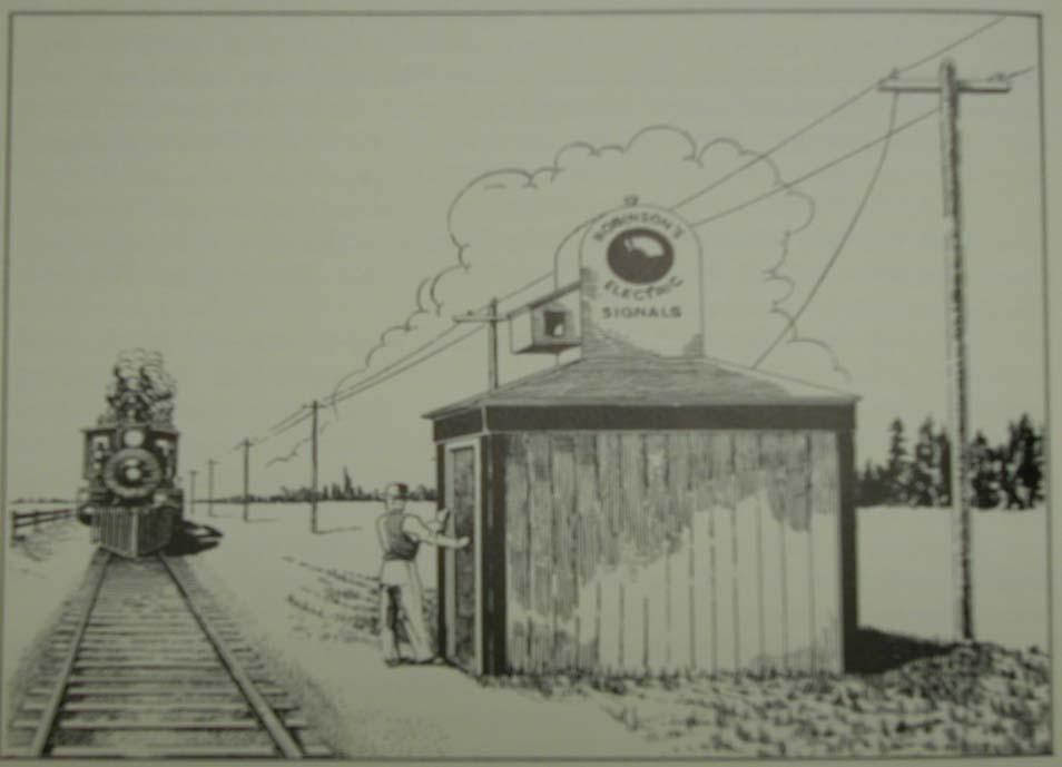
53 The first motor driven highway crossing gate was introduced in 1936 by adapting a semaphore signal mechanism to drive the gate. It was installed on the Illinois Central Railroad. The first use of the rails to carry electric current dates back to Franklin Pope, working with Thomas Edison, conducted an experiment in 1871 using a 42 foot section of rail, but his work was based on the open circuit principle. Interestingly, before producing a closed circuit track circuit, Pope was accidentally electrocuted in his home. The first electric track circuit based on the closed circuit principle was invented by Dr. William Robinson in Robinson s work occurred almost simultaneously with Pope s, and in 1870 he demonstrated a model of his circuit based on an open circuit principle at a fair in New York City. Later that year, Robinson s circuit was installed at Kinzua, PA on the Philadelphia and Erie Railroad. 53

54 54

55 55
56 Robinson discovered the immediate safety risks associated with an open circuit, and worked to produce a closed circuit which he demonstrated in 1872 at the State Fair in Erie, Pennsylvania. Robinson recognized that gravity was a necessary part of the fail safe principle. The first insulated joints necessary for Robinson s track circuit were made of wood. In 1876, fiber insulated rail joints were developed. Bond wires were also invented to be pushed into a hole drilled in the rail and held in place by a pin. 56


57 57


58 58

59 In 1878, Robinson, following many successful installations of his new circuit and signal system, formed the Union Electric Signal Company. On May 1, 1881, George Westinghouse consolidated the Union Electric Signal Company and the Interlocking Switch and Signal Company to form what is now known as the Union Switch & Signal Company. 59

60 On November 22, 1910, the following report was made by the Block Signal and Train Control Board to the Interstate Commerce Commission: Perhaps no single invention in the history of the development of railway transportation has contributed more toward the safety and dispatch in that field than the track circuit. By this invention, simple in itself, the foundation was obtained for the development of practically every one of the intricate systems of railway block signaling in use today, Robinson s circuit is what we now know as the DC Track Circuit and consists of a battery and relay connected to the rails at opposite ends of the circuit. 60
61 61
62 62
63 63

64 64
65 In later years, engineers worked to design a circuit that allowed the battery and relay to be located at the same end of the circuit. It was determined that in order to accomplish the goal of having the relay at the same end of the circuit, the energy source would have to utilize AC current. A rectifier (now known as a diode) was installed at the distant end of the circuit. A higher AC voltage could be applied to the rails which allowed better shunting (sensitivity) where large amounts of rust exist due to infrequent use. In the mid 1960 s everyone was embracing a new device that would revolutionize the world, the transistor. Railroad signal engineers looked for ways to improve the state of the art through the use of solid state electronics. The result was the Solid State Audio Frequency Overlay (AFO) track circuit. The AFO track circuit was unique in that it did not require insulated joints. A transmitter was connected to the rails at one end of the circuit. A receiver was connected to the rails at the other end of the circuit. The fail safe operation is maintained with the AFO circuit. 65

66 66
67 Although the AFO circuit simplified highway crossing circuits by allowing multiple approaches to overlap, it was unable to provide more information than an occupied/unoccupied condition. Once individual track circuits were developed, combinations of track circuit occupancy were used to provide more intelligent control. In highway-rail grade crossing control, circuitry was developed to allow warning devices to begin operating as a train approached a crossing, but permitted the devices to stop operating as soon as the train cleared the crossing This circuit made use of stick relays. A stick circuit allows the train direction to be established through a crossing. 67
68 CONVENTIONAL 3 TRACK CIRCUIT 968' 1T 2T 3T INSULATED JOINT DEFINES CIRCUIT LIMITS MT = CT = MWT = MWT= ERT= APPROACH TIME= 20 SEC. 0 SEC. 20 SEC. 20 SEC. 2 SEC. 22 SEC. APPROACH 30 MPH
69 CONVENTIONAL 3 TRACK CIRCUIT 968' 1T 2T 3T INSULATED JOINT DEFINES CIRCUIT LIMITS MT = CT = MWT = MWT= ERT= APPROACH TIME= 20 SEC. 0 SEC. 20 SEC. 20 SEC. 2 SEC. 22 SEC. APPROACH 30 MPH
70 CONVENTIONAL 3 TRACK CIRCUIT 968' 1T 2T 3T INSULATED JOINT DEFINES CIRCUIT LIMITS MT = CT = MWT = MWT= ERT= APPROACH TIME= 20 SEC. 0 SEC. 20 SEC. 20 SEC. 2 SEC. 22 SEC. APPROACH 30 MPH
71 CONVENTIONAL 3 TRACK CIRCUIT 968' 1T 2T 3T INSULATED JOINT DEFINES CIRCUIT LIMITS MT = CT = MWT = MWT= ERT= APPROACH TIME= 20 SEC. 0 SEC. 20 SEC. 20 SEC. 2 SEC. 22 SEC. APPROACH 30 MPH
72 CONVENTIONAL 3 TRACK CIRCUIT 968' 1T 2T 3T INSULATED JOINT DEFINES CIRCUIT LIMITS MT = CT = MWT = MWT= ERT= APPROACH TIME= 20 SEC. 0 SEC. 20 SEC. 20 SEC. 2 SEC. 22 SEC. APPROACH 30 MPH
73 CONVENTIONAL 3 TRACK CIRCUIT 968' 1T 2T 3T INSULATED JOINT DEFINES CIRCUIT LIMITS MT = CT = MWT = MWT= ERT= APPROACH TIME= 20 SEC. 0 SEC. 20 SEC. 20 SEC. 2 SEC. 22 SEC. APPROACH 30 MPH
74 CONVENTIONAL 3 TRACK CIRCUIT 968' 1T 2T 3T INSULATED JOINT DEFINES CIRCUIT LIMITS MT = CT = MWT = MWT= ERT= APPROACH TIME= 20 SEC. 0 SEC. 20 SEC. 20 SEC. 2 SEC. 22 SEC. APPROACH 30 MPH

75 75

76 Flasher Relay 76
77 In the late 1960 s, the first Solid State Motion Sensor was developed. It was built on principles from the AFO track circuit. The Motion Sensor provided a means to determine if a train was moving toward the crossing, moving away from the crossing or stopped within the approach circuit to a crossing. 77
78 MOTION SENSOR CIRCUIT 1012' T1 R1 T2 R2 TERMINATION SHUNT DEFINES CIRCUIT LIMITS. MT = CT = MWT = MWT= ERT= APPROACH TIME= 20 SEC. 0 SEC. 20 SEC. 20 SEC. 3 SEC. 23 SEC. APPROACH 30 MPH

79 79

80 Product design engineers quickly realized that, with a slight amount of additional information, a Motion Sensor could be adapted to measure train speed by measuring the rate of voltage change against a fixed distance. Although the calculations were performed through analog means, this formed the first Constant Warning Time system. With the development of the microprocessor and the reliability derived from the use of CMOS logic devices, the first HXP-1 Digital Grade Crossing Processor was developed by Harmon Electronics in the early 1970 s. 80
81 CONSTANT WARNING TIME CIRCUIT 1320' T1 R1 T2 R2 TERMINATION SHUNT DEFINES CIRCUIT LIMITS. MT = CT = MWT = MWT= BT= TOTAL WARNING TIME= APT= ERT= APPROACH TIME= 20 SEC. 0 SEC. 20 SEC. 20 SEC. 5 SEC. 25 SEC. 0 SEC. 5 SEC. 30 SEC. APPROACH 30 MPH

82 Today, microprocessors have revolutionized all facets of railroad signaling. Items we now take for granted such as personal computers, keyboards and displays ease user interface with increasingly complex equipment. 82

83 83
84 MUTCD 2003 EDITION PART 8 Traffic Controls for Highway-Rail Grade Crossings Section 8D.07 Traffic Control Signals at or Near Highway-Rail Grade Crossings Guidance: The highway agency with jurisdiction, the regulatory agency with statutory authority, if applicable and the railroad company should jointly determine the preemption operation at highway-rail grade crossings adjacent to signalized highway intersections. When a highway-rail grade crossing is equipped with a flashing-light signal system and is located within 60m (200 ft) of an intersection or midblock location controlled by a traffic control signal, the traffic control signal should be provided with preemption in accordance with Section 4D.13. Coordination with the flashing-light signal system should be considered for traffic control signals located farther than 60m (200 ft) from the highway-rail grade crossing. Factors to be considered should include traffic volumes, vehicle mix, vehicle and train approach speeds, frequency of trains and queue lengths. Standard: If preemption is provided, the normal sequence of traffic control signal indications shall be preempted upon the approach of trains to avoid entrapment of vehicles on the highway-rail grade crossing by conflicting aspects of the traffic control signals and the highway-rail grade crossing flashing-light signals. 84
85 This preemption feature shall have an electrical circuit of the closedcircuit principle, or a supervised communication circuit between the control circuits of the highway-rail grade crossing warning system and the traffic control signal controller. The traffic control signal controller preemptor shall be activated via the supervised communication circuit or the electrical circuit that is normally energized by the control circuits of the highway-rail grade crossing warning system. The approach of a train to a highway-rail grade crossing shall de-energize the electrical circuit or activate the supervised communication circuit, which in turn shall activate the traffic control signal controller preemptor. This shall establish and maintain the preemption condition during the time the highway-rail grade crossing warning system is activated, except that when crossing gates exist, the preemption condition shall be maintained until the crossing gates are energized to start their upward movement. When multiple or successive preemptions occur, train activation shall receive first priority. 85
86 Section 8A.01 MUTCD 2003 EDITION DEFINITIONS Standard: 1. Advance Preemption the notification of an approaching train that is forwarded to the highway traffic signal controller unit or assembly by the railroad equipment in advance of the activation of the railroad warning devices. 2. Advance Preemption Time the period of time that is the difference between the required maximum highway traffic signal preemption time and the activation of the railroad warning devices. 3. Cantilevered Signal Structure a structure that is rigidly attached to a vertical pole and is used to provide overhead support of signal units. 4. Clear Storage Distance the distance available for vehicle storage measured between 1.8 m (6 ft) from the rail nearest the intersection to the intersection stop line or the normal stopping point on the highway. At skewed highway-rail grade crossings and intersections, the 1.8 m (6 ft) distance shall be measured perpendicular to the nearest rail either along the centerline or edge line of the highway, as appropriate, to obtain the shorter distance. Where exit gates are used, the distance available for vehicle storage is measured from the point where the rear of the vehicle would be clear of the exit gate arm. In cases where the exit gate arm is parallel to the track(s) and is not perpendicular to the highway, the distance is measured either along the centerline or edge line of the highway, as appropriate, to obtain the shorter distance. 86
87 CLEAR STORAGE DISTANCE (two-quadrant gate system) Clear Storage Distance at 90 Degree Crossing Clear Storage Distance shown in Red 87
88 CLEAR STORAGE DISTANCE (two-quadrant gate system) Clear Storage Distance at Skewed Crossing Clear Storage Distance shown in Red 88
89 CLEAR STORAGE DISTANCE (four-quadrant gate system) Clear Storage Distance at 90 Degree Crossing Clear Storage Distance shown in Red 89
90 CLEAR STORAGE DISTANCE (four-quadrant gate system) Clear Storage Distance at Skewed Crossing Clear Storage Distance shown in Red 90
91 5. Design Vehicle the longest vehicle permitted by statute of the road authority (State or other) on that roadway. 6. Dynamic Envelope the clearance required for the train and its cargo overhang due to any combination of loading, lateral motion, or suspension failure (see Figure 8A-1). 7. Dynamic Exit Gate Operating Mode a mode of operation where the exit gate operation is based on the presence of vehicles within the minimum track clearance distance. 8. Exit Gate Clearance Time for Four-Quadrant Gate systems, the exit gate clearance time is the amount of time provided to delay the descent of the exit gate arm(s) after entrance gate arm(s) begin to descend. 9. Exit Gate Operating Mode for Four-Quadrant Gate systems, the mode of control used to govern the operation of the exit gate arms. 10. Flashing-Light Signals a warning device consisting of two red signal indications arranged horizontally that are activated to flash alternately when a train is approaching or present at a highway-rail grade crossing. 11. Interconnection the electrical connection between the railroad active warning system and the highway traffic signal controller assembly for the purpose of preemption. 12. Maximum Highway Traffic Signal Preemption Time the maximum amount of time needed following initiation of the preemption sequence for the highway traffic signals to complete the timing of the right-of-way transfer time, queue clearance time, and separation time. 91
92 13. Minimum Track Clearance Distance for standard twoquadrant railroad warning devices, the minimum track clearance distance is the length along a highway at one or more railroad tracks, measured either from the highway stop line, warning device, or 3.7 m (12 ft) perpendicular to the track centerline, to 1.8 m (6 ft) beyond the track(s) measured perpendicular to the far rail, along the centerline or edge line of the highway, as appropriate, to obtain the longer distance. For Four- Quadrant Gate systems, the minimum track clearance distance is the length along a highway at one or more railroad tracks, measured either from the highway stop line or entrance warning device, to the point where the rear of the vehicle would be clear of the exit gate arm. In cases where the exit gate arm is parallel to the track(s) and is not perpendicular to the highway, the distance is measured either along the centerline or edge of the highway, as appropriate, to obtain the longer distance. 92
93 MTCD (two-quadrant gate system) Minimum Track Clearance Distance for two-quadrant gate system MTCD shown in Red 93
94 MTCD (two-quadrant gate system) Minimum Track Clearance Distance for two-quadrant gate system MTCD shown in Red 94
95 MTCD (two-quadrant gate system) Minimum Track Clearance Distance for two-quadrant gate system MTCD shown in Red 95
96 MTCD (four-quadrant gate system) Minimum Track Clearance Distance for four-quadrant gate system Additional MTCD shown in Red 96
97 MTCD (four-quadrant gate system) Minimum Track Clearance Distance for four-quadrant gate system Additional MTCD shown in Red 97
98 14. Minimum Warning Time Through Train Movements the least amount of time active warning devices shall operate prior to the arrival of a train at a highway-rail grade crossing. 15. Preemption the transfer of normal operation of highway traffic signals to a special control mode. 16. Pre-signal supplemental highway traffic signal faces operated as part of the highway intersection traffic signals, located in a position that controls traffic approaching the highway-rail grade crossing in advance of the intersection. 17. Queue Clearance Time the time required for the design vehicle of maximum length stopped just inside the minimum track clearance distance to start up and move through and clear the entire minimum track clearance distance. If presignals are present, this time shall be long enough to allow the vehicle to move through the intersection, or to clear the tracks if there is sufficient clear storage distance. If a Four-Quadrant Gate system is present, this time shall be long enough to permit the exit gate arm to lower after the design vehicle is clear of the minimum track clearance distance. 18. Right-of-Way Transfer Time the maximum amount of time needed for the worst case condition, prior to display of the track clearance green interval. This includes any railroad or highway traffic signal control equipment time to react to a preemption call, and any traffic control signal green, pedestrian walk and clearance, yellow change, and red clearance intervals for conflicting traffic. 19. Separation Time the component of maximum highway traffic signal preemption time during which the minimum track clearance distance is clear of vehicular traffic prior to the arrival of the train. 98
99 20. Simultaneous Preemption notification of an approaching train is forwarded to the highway traffic signal controller unit or assembly and railroad active warning devices at the same time. 21. Timed Exit Gate Operating Mode a mode of operation where the exit gate descent is based on a predetermined time interval. 22. Vehicle Intrusion Detection Devices a detector or detectors used as a part of a system incorporating processing logic to detect the presence of vehicles within the minimum track clearance distance and to control the operation of the exit gates. 23. Wayside Equipment the signals, switches, and/or control devices for railroad operations housed within one or more enclosures located along the railroad right-of-way and/or on railroad property. 99
100 MUTCD 2003 EDITION PART 4 Highway Traffic Signals Section 4D.02 Responsibility for Operation and Maintenance Guidance: Prior to installing any traffic control signal, the responsibility for the maintenance of the signal and all of the appurtenances, hardware, software and the timing plan(s) should be clearly established. The responsible agency should provide for the maintenance of the traffic control signal and all of its appurtenances in a competent manner. To this end the agency should: A. Keep every controller assembly in effective operation in accordance with its predetermined timing schedule; check the operation of the controller assembly frequently enough to ensure that it is operating in accordance with the predetermined timing schedule and ensure that a record of all timing changes is maintained and that only authorized persons make timing changes. 100
101 MUTCD 2003 EDITION PART 4 Highway Traffic Signals Section 4D.13 Preemption and Priority Control of Traffic Control Signals Standard: During the transition into preemption control: A. The yellow change interval, and any red clearance interval that follows, shall not be shortened or omitted. B. The shortening or omission of any pedestrian walk interval and/or pedestrian change interval shall be permitted. C. The return to the previous steady green signal indication shall be permitted following a steady yellow signal indication in the same signal face, omitting the red clearance interval, if any. During preemption control and during the transition out of preemption control: A. The shortening or omission of any yellow change interval, and of any red clearance interval that follows, shall not be permitted. B. A signal indication sequence from a steady yellow signal indication to a steady green signal indication shall not be permitted. 101
102 Guidance: If a traffic control signal is installed near or within a highwayrailroad grade crossing or if a highway-railroad grade crossing with active traffic control devices is within or near a signalized highway intersection, Chapter 8D should be consulted. Section 4E.07 Countdown Pedestrian Signals Standard: If used, countdown pedestrian signals shall consist of Portland orange numbers that are at least 150 mm (6 in) in height on a black opaque background. The countdown pedestrian signal shall be located immediately adjacent to the associated UPRAISED HAND (symbolizing DONT WALK) pedestrian signal head indication. If used, the display of the number of remaining seconds shall begin only at the beginning of the pedestrian change interval. After the countdown displays zero, the display shall remain dark until the beginning of the next countdown. If used, the countdown pedestrian signal shall display the number of seconds remaining until the termination of the pedestrian change interval. Countdown displays shall not be used during the walk interval nor during the yellow change interval of a concurrent vehicular phase. Guidance: Because some technology includes the countdown pedestrian signal logic in a separate timing device that is independent of the timing in the traffic signal controller, care should be exercised by the engineer when timing changes are made to pedestrian change intervals. If the pedestrian change interval is interrupted or shortened as a part of a transition into a preemption sequence (see Section 4E.10), the countdown pedestrian signal display should be discontinued and go dark immediately upon activation of the preemption transition. 102
103 MUTCD 2003 EDITION PART 4 Highway Traffic Signals Section 4E.10 Pedestrian Intervals and Signal Phases Standard: When pedestrian signal heads are used, a WALKING PERSON (symbolizing WALK) signal indication shall be displayed only when pedestrians are permitted to leave the curb or shoulder. A pedestrian clearance time shall begin immediately following the WALKING PERSON (symbolizing WALK) signal indication. The first portion of the pedestrian clearance time shall consist of a pedestrian change interval during which a flashing UPRAISED HAND (symbolizing DONT WALK) signal indication shall be displayed. The remaining portions shall consist of the yellow change interval and any red clearance interval (prior to a conflicting green being displayed), during which a flashing or steady UPRAISED HAND (symbolizing DONT WALK) signal indication shall be displayed. If countdown pedestrian signals are used, a steady UPRAISED HAND (symbolizing DONT WALK) signal indication shall be displayed during the yellow change interval and any red clearance interval (prior to a conflicting green being displayed) (see Section 4E.07). At intersections equipped with pedestrian signal heads, the pedestrian signal indications shall be displayed except when the vehicular traffic control signal is being operated in the flashing mode. At those times, the pedestrian signal lenses shall not be illuminated. 103
104 MUTCD 2003 EDITION PART 4 Highway Traffic Signals Section 4E.10 Pedestrian Intervals and Signal Phases Guidance: Except as noted in the Option, the walk interval should be at least 7 seconds in length so that pedestrians will have adequate opportunity to leave the curb or shoulder before the pedestrian clearance time begins. Option: If pedestrian volumes and characteristics do not require a 7-second walk interval, walk intervals as short as 4 seconds may be used. 104
105 The section for the AREMA C & S manual Part Part Revision 2004 has been deleted due to copy right law
106 Ø8 Ø3 Ø2 PED Ø2 Ø1 Ø8 PED Ø4 PED Ø5 Ø6 Ø6 PED Ø7 Ø4 8Ø+PED PHASE SEQUENCE Ø1 Ø2P Ø2 Ø3 Ø4 Ø4P Ø5 Ø6 Ø6P Ø7 Ø8P Ø8 106
107 Ø8 Ø3 Ø2 PED Ø2 Ø1 Ø8 PED Ø4 PED Ø5 Ø6 Ø6 PED Ø7 Ø4 8Ø+PED PHASE SEQUENCE Ø1 Ø2P Ø2 Ø3 Ø4P Ø4 Ø5 Ø6 Ø6P Ø7 Ø8P Ø8 107
108 RAILROAD PREEMPT PHASE SEQUENCE Ø1 Ø6 Ø8 Ø3 Ø1 Ø5 Ø6 Ø2 Ø7 Ø3 Ø8 Ø4 Ø2 Ø5 Ø7 Ø4 Ø7 Ø4 Ø6 Ø2 Ø1 Ø6 Ø3 108
109 109
110 110

111 111
112 112

113 113
114 114

115 115

116 116

117 117
118 118
119 119
120 120
121 121
122 122

123 123

124 124

125 125
126 126

127 127
128 128
129 129
130 130

131 131

132 132

133 133
134 134

135 135
136 136
137 137
138 138
139 Vehicles Dynamics for Computing Track Clearance Phase Detection Vehicles Dynamics when Accelerating from a Stopped Position Time (s) to start moving for the Nth vehicle Vehicle N Fast Car Average Thru Car Average Left T. Car Slow Car Average SU Average WB-15 Slow WB-15 Average School Bus Methodology from: Modeling Queued Driver Behavior At Signalized Junctions By Jim Bonneson Transportation Research Record (1365) pp Numbers from: 1. Acceleration Characteristics of Starting Vehicles By Gary Long, University of Florida TRB 2000 Preprint Paper No School Bus Acceleration and Sight Distance J.L. Gattis, S.H. Nelson, and J.D. Tubbs Paper Submission to ASCE Assumptions: 1 seconds initial perception-reaction time (Bonneson s tau) The following saturation flows and vehicle queue spacing: Sat. Flow Queue space (vphgpl) (ft/veh) Fast Car Average Thru Car Average Left T. Car Slow Car Average SU Average WB Slow WB Average School Bus
140 Vehicles Dynamics when Accelerating from a Stopped Position Distance traveled (ft) in time T from a stopped position Time T (s) Fast Car Average Thru Car Average Left T. Car Slow Car Average SU Average WB-15 Slow WB-15 Average School Bus Methodology from: Modeling Queued Driver Behavior At Signalized Junctions By Jim Bonneson Transportation Research Record (1365) pp Numbers from: 1. Acceleration Characteristics of Starting Vehicles By Gary Long, University of Florida TRB 2000 Preprint Paper No School Bus Acceleration and Sight Distance J.L. Gattis, S.H. Nelson, and J.D. Tubbs Paper Submission to ASCE 140
141 Basic Preempt Time Line TRAIN ARRIVAL AT LTS CROSSING FLASH GATE DESCENT GATE HORIZ YEL RED TRACK CLEAR SEPARATION
142 Preempt Time Line TRAIN ARRIVAL AT CROSSING
143 Special Geometric Conditions Must Always be Considered 143
144 Burbank, CA San Fernando Road and Buena Vista Street 2300 North Buena Vista Street NORTH SCRRA Mainline 52º Automatic gate 50 feet 2400 North San Fernando Boulevard 144
145 MUTCD Section 8B.06 Turn Restrictions During Preemption Guidance: At a signalized intersection that is located within 60 m (200 ft) of a highway-rail grade crossing, measured from the edge of the track to the edge of the roadway, where the intersection traffic control signals are preempted by the approach of a train, all existing turning movements toward the highway-rail grade crossing should be prohibited during the signal preemption sequences. Option: A blank-out or changeable message sign and/or appropriate highway traffic signal indication or other similar type sign may be used to prohibit turning movements toward the highway-rail grade crossing during preemption. The R3-1a and R3-2a signs shown in Figure 8B-3 may be used for this purpose. 145
146 Burbank, CA Driver Perspective View Looking East Railroad warning lights Left arrow indications Circular indications 146
147 Burbank, CA Driver View of Railroad Warning Devices Automatic gate 147
148 VEHICLES MAKING LEFT TURN DURING LEFT TURN PHASE - NO PREEMPTION APPROACHING TRAIN / SIMULTANEOUS PREEMPTION REQUEST LEFT TURN PHASE TERMINATES 148
149 VEHICLE AHEAD OF TRACTOR-TRAILER STOPS FOR DESCENDING GATE TRACTOR-TRAILER BLOCKS PATH FOR VEHICLES EXITING MTCD 149

150 150
151 Presignal Applications at Highway-Rail Grade Crossings MUTCD Application of Presignals Institute of Transportation Engineers When is a Presignal not a Presignal 151
152 MUTCD Application of Presignals Part 8 Traffic Controls for Highway-Rail Grade Crossings Section 8D.07 Traffic Control Signals at or Near Highway-Rail Grade Crossings Standard: If a pre-signal is installed at an interconnected highway-rail grade crossing near a signalized intersection, a STOP HERE ON RED (R10-6) sign shall be installed near the pre-signal or at the stop line if used. If there is a nearby signalized intersection with insufficient clear storage distance for a design vehicle, or the highway-rail grade crossing does not have gates, a NO TURN ON RED (R10-11) sign shall be installed for the approach that crosses the railroad track. 152
153 Other MUTCD Parts Relating Indirectly to Presignals Part 4 Highway Traffic Signals Section 4D.15 Size, Number and Location of Signal Faces by Approach Standard: The signal faces for each approach to an intersection or a midblock location shall be provided as follows: A. A minimum of two signal faces shall be provided for the major movement on the approach, even if the major movement is a turning movement. 1. A signal face installed to satisfy the distance requirements as described in Paragraphs B and C in the first Standard of this Section, and at least one and preferably both of the signal faces required by Paragraph A in this Standard shall be located: (a)not less than 12 m (40 ft) beyond the stop line. 153
154 Presignal Upstream 40' MINIMUM 154
155 Presignal Downstream 40' MINIMUM 155
156 Presignal Downstream- Minimum CSD Near Side of Intersection 40' MINIMUM 156

157 157
158 Institute of Transportation Engineers PREEMPTION OF TRAFFIC SIGNALS NEAR RAILROAD CROSSINGS Pre-signal mast arm poles can be located upstream or downstream from the railroad crossing. In all cases, pre-signal poles must be located to maintain visibility of the railroad flashing lights. If an existing railroad cantilever exists and upstream pre-signals are used, they should be mounted on the cantilever if permitted by the railroad or regulatory agency. 158

159 Indiana & Ohio Railroad Galbraith Road Presignal 159

160 Indiana & Ohio Railroad Galbraith Road Presignal 160

161 Indiana & Ohio Railroad Galbraith Road Presignal 161
162 Institute of Transportation Engineers PREEMPTION OF TRAFFIC SIGNALS NEAR RAILROAD CROSSINGS Pre-signals or queue-cutter signals should also be used wherever railroad warning devices consist only of flashing light signals. However, this can result in conflicting signal indications between the flashing red lights at the crossing and a display of track clearance green beyond the crossing. To eliminate this conflict, the installation of gates may be necessary. 162
163 Institute of Transportation Engineers PREEMPTION OF TRAFFIC SIGNALS NEAR RAILROAD CROSSINGS Pre-Signal Phasing and Operation The pre-signal intervals should be progressively timed with the downstream signal intervals to provide a delay adequate to clear vehicles from the track area and the downstream intersection. Vehicles that are required to make a mandatory stop such as school buses, vehicles hauling hazardous materials, etc., should be considered when determining the delay time to ensure that they will not be stopped within the minimum track clearance distance (see Appendix C). 163
164 Institute of Transportation Engineers PREEMPTION OF TRAFFIC SIGNALS NEAR RAILROAD CROSSINGS Pre-Signal Phasing and Operation Where the clear storage distance is inadequate to store a design vehicle clear of the minimum track clearance distance and crossing gates are present, consideration should be given to installation of vehicle detection within the clear storage distance to prevent vehicles from being trapped within the minimum track clearance distance by extending the clear track green interval. 164

165 Mustang Court Grapevine, TX FWWR 165
166 When is a Presignal not a Presignal? When it s a Queue-Cutter Signal! Looks like a presignal. Located at the crossing like a presignal. When Clear Storage Distance is greater than
167 When is a Presignal not a Presignal? Queue Cutter Signal Interconnected for simultaneous preemption. May or may not function as a part of the downstream intersection signals. Utilizes downstream vehicle detection to change to red to prevent standing vehicles within MTCD. 167
168 Institute of Transportation Engineers PREEMPTION OF TRAFFIC SIGNALS NEAR RAILROAD CROSSINGS If the clear storage distance is greater than 120 ft (37 m), any traffic signal heads located at a railroad crossing should be considered to be a separate mid-block crossing (a queue-cutter signal), and not a presignal. However, coordination with the intersection signals may still be appropriate. 168
169 Queue Cutter Signal and Downstream Detector >120' 40' MINIMUM QUEUE DETECTOR QUEUE DETECTOR 169

170 Questions? 170
This Manual Part recommends functional/operating guidelines for control of automatic grade crossing warning systems. Draft
 Recommended Functional/Operating Guidelines for Control of Automatic Grade Crossing Warning Systems Revised 2017 (6 Pages) A. Purpose This Manual Part recommends functional/operating guidelines for control
TECHNICAL COMMITTEE: Railroad and Light Rail Transit and Signals Technical Committees
 1 2 3 ATTACHMENT NO. 18 Joint RRLRT & Signals #1 4 5 6 7 8 9 10 11 12 13 14 15 16 17 18 19 20 21 22 23 24 25 26 27 28 29 30 31 32 33 34 35 36 37 38 39 40 41 42 NOTE: This is a recommendation by NCUTCD
11/17/2015 Copyright 2015 by CTC, Inc. (CTC) 1
 1") National Highway-Rail Grade Crossing Safety Training Conference November 3, 2015 Copyright 2015 by CTC, Inc. (CTC) The purpose of this workshop is to highlight a number of design elements typically encountered
National Highway-Rail Grade Crossing Safety Training Conference November 3, 2015 Copyright 2015 by CTC, Inc. (CTC) The purpose of this workshop is to highlight a number of design elements typically encountered
ATTACHMENT NO. 11. RRLRT No. 2. Railroad / Light Rail Transit Technical Committee TECHNICAL COMMITTEE: Busway Grade Crossings STATUS/DATE OF ACTION
 ATTACHMENT NO. 11 RRLRT No. 2 TECHNICAL COMMITTEE: TOPIC: Railroad / Light Rail Transit Technical Committee Busway Grade Crossings STATUS/DATE OF ACTION RRLRT TC Draft: 06/23/2011 RRLRT TC Approval: 06/27/2014
800 RAIL GRADE CROSSINGS Traffic Engineering Manual
 TABLE OF CONTENTS Part 8 - RAIL GRADE CROSSINGS 800 GENERAL...8-3 801 SIGNING...8-3 801-1 General...8-3 801-2 STOP Signs at Highway-Rail Grade Crossings... 8-3 801-2.1 General...... 8-3 801-2.2 Application
Oregon Supplement to the Manual on Uniform Traffic Control Devices. Adopted July 2005 by OAR
 Oregon Supplement to the Manual on Uniform Traffic Control Devices Adopted July 2005 by OAR 734-020-0005 2003 Edition Oregon Supplement to the MUTCD Page 2 INTRODUCTION Traffic control devices installed
For Signals Training Consortium Use Only
 Introduction and Overview to Highway Grade Crossings Course 104 PARTICIPANT GUIDE Introduction and Overview to Highway Grade Crossings Participant Guide Signals Maintenance Training Consortium COURSE 104
PART 10. TRAFFIC CONTROLS FOR HIGHWAY-LIGHT RAIL TRANSIT GRADE CROSSINGS TABLE OF CONTENTS
 Part 10. Traffic Controls for Highway-Light Rail Transit Grade Crossings Page 10TC-1 PART 10. TRAFFIC CONTROLS FOR HIGHWAY-LIGHT RAIL TRANSIT GRADE CROSSINGS TABLE OF CONTENTS CHAPTER 10A. GENERAL..........................................
Shortening or omitting a pedestrian change interval when transitioning into preemption
 Signals #1 NOTE: This is a recommendation by the Signals Technical Committee of the NCUTCD. It is being distributed to the NC Sponsoring agencies for review and is subject to revision. This recommendation
CHAPTER 2G. PREFERENTIAL AND MANAGED LANE SIGNS
 2011 Edition - Revision 2 Page 275 Section 2G.01 Scope CHAPTER 2G. PREFERENTIAL AND MANAGED LANE SIGNS 01 Preferential lanes are lanes designated for special traffic uses such as high-occupancy vehicles
MANUAL ON UNIFORM TRAFFIC CONTROL DEVICES INTRODUCTION
 2011 Edition Page I-1 MANUAL ON UNIFORM TRAFFIC CONTROL DEVICES INTRODUCTION 01 Traffic control devices shall be defined as all signs, signals, markings, and other devices used to regulate, warn, or guide
TECHNICAL COMMITTEE: Railroad and Light Rail Transit and Signals Technical Committees
 1 2 Joint RRLRT & Signals #1 3 4 5 6 7 8 9 10 11 12 13 14 15 16 17 18 19 20 21 22 23 24 25 26 27 28 29 30 31 32 33 34 35 36 37 38 39 40 41 42 43 44 NOTE: This is a draft recommendation by the Railroad
Glossary of Terms. ABANDONMENT The permanent cessation of rail activity on a given line of railroad.
 Glossary of Terms AAR/DOT CROSSING NUMBER A uniform numbering system in which a unique designation is assigned to every highway-rail grade crossing in the nation. It consists of a six digit number followed
Designing Safety into Highway-Rail Grade Crossing Projects
 Designing Safety into Highway-Rail Grade Crossing Projects February 13, 2017 Copyright 2016 by CTC, Inc. (CTC) Overview of Grade Crossing Safety 2 A train strikes a vehicle or person every 4 hours in U.S.
Railroad-Highway Grade Crossing Analysis for Corridor Planning Projects
 Railroad-Highway Grade Crossing Analysis for Corridor Planning Projects Word Count: 4,305 Submission Date: August 1, 2015 Author: Adriana Rodriguez, E.I Assistant Engineer Parsons Brinckerhoff 1420 South
(This page left intentionally blank)
") (This page left intentionally blank) 2011 Edition - Revision 2 Page 771 Section 8A.01 Introduction PART 8 TRAFFIC CONTROL FOR RAILROAD AND LIGHT RAIL TRANSIT GRADE CROSSINGS CHAPTER 8A. GENERAL 01 Whenever
(This page left intentionally blank) 2011 Edition - Revision 2 Page 771 Section 8A.01 Introduction PART 8 TRAFFIC CONTROL FOR RAILROAD AND LIGHT RAIL TRANSIT GRADE CROSSINGS CHAPTER 8A. GENERAL 01 Whenever
Part 8. TRAFFIC CONTROL FOR RAILROAD AND LIGHT RAIL TRANSIT GRADE CROSSINGS
 Part 8. TRAFFIC CONTROL FOR RAILROAD AND LIGHT RAIL TRANSIT GRADE CROSSINGS TABLE OF CONTENTS MN Rev. 6 MN Rev. 6 MN Rev. 6 Chapter 8A. GENERAL Page Section 8A.1 Introduction............................................................
OKLAHOMA SCHOOL BUS DRIVER MANUAL TRAINING MANUAL FOR OKLAHOMA SCHOOL BUS DRIVER CERTIFICATION
 OKLAHOMA SCHOOL BUS DRIVER MANUAL TRAINING MANUAL FOR OKLAHOMA SCHOOL BUS DRIVER CERTIFICATION JANET BARRESI STATE SUPERINTENDENT of PUBLIC INSTRUCTION OKLAHOMA STATE DEPARTMENT of EDUCATION It is the
MUTCD Part 6: Temporary Traffic Control
 MUTCD Part 6: Temporary Traffic Control OMUTCD English units are preferred. OHIO MANUAL OF UNIFORM TRAFFIC CONTROL DEVICES TABLE OF CONTENTS PREFACE INTRODUCTION TABLE OF CONTENTS PART 1. GENERAL Chapter
TEMPORARY TRAFFIC CONTROL GUIDELINES FOR HIGHWAY-RAIL GRADE CROSSINGS
 TEMPORARY TRAFFIC CONTROL GUIDELINES FOR HIGHWAY-RAIL GRADE CROSSINGS 1.0 INTRODUCTION 1.1 Purpose The Southern California Regional Rail Authority (SCRRA) is the designated track owner of the Metrolink
Fundamentals of Traffic Control Devices
 Fundamentals of Traffic Control Devices Traffic Engineering & Operations October 8, 2014 Raj Ponnaluri, Angela Wilhelm, and Christopher Lewis Agenda Agenda Signs Pavement Markings Signals Traffic Operations
PART 4 HIGHWAY TRAFFIC SIGNALS
 2016 Edition Page 111 PART 4 HIGHWAY TRAFFIC SIGNALS CHAPTER 4A. GENERAL [This is a new section. There is no corresponding section in the MUTCD.] Section 4A.100 Traffic Control Device Alternatives for
Yellow and Red Intervals It s Just a Matter of Time. 58 th Annual Alabama Transportation Conference February 9, 2015
 Yellow and Red Intervals It s Just a Matter of Time 58 th Annual Alabama Transportation Conference February 9, 2015 Presentation Content Background on Timing Methodology Findings and Recommendations from
SCOPE Application, Design, Operations,
 SCOPE Application, Design, Operations, Maintenance, etc.: Typical Traffic Control Signals Pedestrian Hybrid Beacons Emergency Vehicle One-Lane/Two-Way Facilities, Freeway Entrance Ramps, and Movable Bridges
Access Location, Spacing, Turn Lanes, and Medians
 Design Manual Chapter 5 - Roadway Design 5L - Access Management 5L-3 Access Location, Spacing, Turn Lanes, and Medians This section addresses access location, spacing, turn lane and median needs, including
MEMORANDUM. Background
 MEMORANDUM DATE: September 2, 2013 TO: FROM: SUBJECT: PROJECT: City of Fife Attn: Russ Blount 5411 23 rd Street East Fife, WA 98424 Al Tebaldi, PE 54 th Avenue East Crossing Safety Memorandum FIFE0000-0177-
CIRCULAR NO. O-13. Recommended Practices for Manual Protection of Highway/Railway Grade Crossings
 CIRCULAR NO. O-13 Recommended Practices for Manual Protection of Highway/Railway Grade Crossings Effective: October 1, 2004 CONTENTS 1. SCOPE 2. GENERAL PRINCIPLES 3. DEFINITIONS 4. PROTECTION REQUIRED
Attachment No. 13. National Committee on Uniform Traffic Control Devices RWSTC RECOMMENDATION FOLLOWING SPONSOR COMMENTS
 1 2 3 4 Attachment No. 13 5 6 7 8 9 10 11 12 13 14 15 16 17 18 19 20 21 22 23 24 25 26 27 28 29 30 31 32 33 34 35 36 37 38 39 40 41 42 43 RWSTC agenda item IV. 2 June 2011 National Committee on Uniform
The 2009 Manual on Uniform Traffic Control Devices (MUTCD) (Brief) Highlights for Arizona Practitioners. Arizona Department of Transportation
 (Brief) Highlights for Arizona Practitioners. Arizona Department of Transportation") The 2009 Manual on Uniform Traffic Control Devices (MUTCD) (Brief) Highlights for Arizona Practitioners Arizona Department of Transportation New 2009 MUTCD 9 Parts (down from 10 in 2003) 816 pages (up
The 2009 Manual on Uniform Traffic Control Devices (MUTCD) (Brief) Highlights for Arizona Practitioners Arizona Department of Transportation New 2009 MUTCD 9 Parts (down from 10 in 2003) 816 pages (up
Ohio Department of Transportation Edition of the OMUTCD It s Here!
 Ohio Department of Transportation John R. Kasich, Governor Jerry Wray, Director 2012 Edition of the OMUTCD It s Here! June 6, 2012 Here are reasons why we have a Manual of Uniform Traffic Control Devices
EWC EARLY WARNING CONTROL OPERATIONAL PRESENTATION. Charles Dickens (757)
") EARLY WARNING CONTROL OPERATIONAL PRESENTATION Charles Dickens (757) 831-2626 Controls still continue to use the foundations of technologies that were developed in the 1970 s. Because of the perceived
EARLY WARNING CONTROL OPERATIONAL PRESENTATION Charles Dickens (757) 831-2626 Controls still continue to use the foundations of technologies that were developed in the 1970 s. Because of the perceived
MUTCD Part 6G: Type of Temporary Traffic Control Zone Activities
 MUTCD Part 6G: Type of Temporary Traffic Control Zone Activities 6G.01 Typical Applications Each temporary traffic control (TTC) zone is different. Many variables, such as location of work, highway type,
Memorandum MAR or in part.
 Interim U.& Department of Transportation federal Highway Administration Memorandum Correction issued 3/21/2018 Subject: - INFORMATION: MUTCD Approval for Optional Use of Pedestrian-Actuated Rectangular
Developed by: The American Traffic Safety Services Association (ATSSA) 15 Riverside Parkway, Suite 100 Fredericksburg, VA
 15 Riverside Parkway, Suite 100 Fredericksburg, VA") Addendum Developed by: The American Traffic Safety Services Association (ATSSA) 15 Riverside Parkway, Suite 100 Fredericksburg, VA 22406-1022 800-272-8772 This material is based upon work supported by
Addendum Developed by: The American Traffic Safety Services Association (ATSSA) 15 Riverside Parkway, Suite 100 Fredericksburg, VA 22406-1022 800-272-8772 This material is based upon work supported by
Traffic Signal Design
 Traffic Signal Design Instructor: S. M. Mahdi Amiripour m.amiripour@gmail.com 2 Introduction Intersection is an area shared by two or more roads Designated for the vehicles to turn to different directions
GUIDELINES FOR EMERGENCY TRAFFIC CONTROL
 GUIDELINES FOR EMERGENCY TRAFFIC CONTROL TABLE OF Contents Page Introduction...1 Chapter 6I of the 2009 MUTCD...2 Reason for Control...6 Components of Incident Management Area...7 Traffic Control Devices
CHAPTER 6H. TYPICAL APPLICATIONS
 2006 Edition Page 6H-1 CHAPTER 6H. TYPICAL APPLICATIONS Section 6H.01 Typical Applications Support: Whenever the acronym TTC is used in this Chapter, it refers to temporary traffic control. Standard: The
Chapter 2: Standards for Access, Non-Motorized, and Transit
 Standards for Access, Non-Motorized, and Transit Chapter 2: Standards for Access, Non-Motorized, and Transit The Washtenaw County Access Management Plan was developed based on the analysis of existing
TRANSMITTAL LETTER. Revision to Publication 149, Chapter 20 (Criteria for the Design of Traffic Signal Supports) - March 2009 Edition
 - March 2009 Edition") OS-299 (7-08) TRANSMITTAL LETTER PUBLICATION: Publication 149 - Traffic Signal Design Handbook DATE: 10/14/10 SUBJECT: Revision to Publication 149, Chapter 20 (Criteria for the Design of Traffic Signal
OS-299 (7-08) TRANSMITTAL LETTER PUBLICATION: Publication 149 - Traffic Signal Design Handbook DATE: 10/14/10 SUBJECT: Revision to Publication 149, Chapter 20 (Criteria for the Design of Traffic Signal
RE: City of Portland Request to Experiment with HAWK/Bike signal
 October 4, 2005 Regina S. McElroy, Director Office of Transportation Operations HOTO Room 3401 400 7 th Street, S.W. Washington, D.C. 20590 RE: City of Portland Request to Experiment with HAWK/Bike signal
GRADE CROSSINGS STANDARDS
 GRADE CROSSINGS STANDARDS February, 2014 TABLE OF CONTENTS PART A INTRODUCTION... 3 1 CITATIONS... 3 2 INTERPRETATION... 3 PART B - EXISTING CROSSINGS... 4 3 GRADE CROSSING SURFACE... 4 4 RAILWAY CROSSING
Flashing Yellow Arrow Left-Turn Signal Guidelines
 Flashing Yellow Arrow Left-Turn Signal Guidelines General What Is It? It s a new type of signal placed OVER the left-turn lane at a signalized intersection. The signal display includes a flashing yellow
Abstract. Background. protected/permissive operation. Source: Google Streetview, Fairview/Orchard intersection
 ITE 2015 Western District Annual Meeting Ada County Highway District s Flashing Yellow Arrow Initiative Primary Author: Tim Curns, PE Ada County Highway District Traffic Engineer Author: Andrew Cibor,
ITE 2013 Annual Meeting Session 36. Utah Statewide Pedestrian Treatment Guidance Manual Standards for At-Grade Crossings F-ST99(180)
") ITE 2013 Annual Meeting Session 36 Utah Statewide Pedestrian Treatment Guidance Manual Standards for At-Grade Crossings 10661 F-ST99(180) John G. Van Hoff, P.E. Travis Bailey, E.I.T. John.vanhoff@aecom.com
ITE 2013 Annual Meeting Session 36 Utah Statewide Pedestrian Treatment Guidance Manual Standards for At-Grade Crossings 10661 F-ST99(180) John G. Van Hoff, P.E. Travis Bailey, E.I.T. John.vanhoff@aecom.com
DPS 201 RECTANGULAR RAPID FLASHING BEACON (RRFB)
") DPS 201 RECTANGULAR RAPID FLASHING BEACON (RRFB) WHY? PEDESTRIANS NEED TO CROSS CASE STUDY: RRFB (ST. PETERSBURG, FL) St. Petersburg, FL Problem/Background Multi-lane, high-speed roadways Conflicts at
DPS 201 RECTANGULAR RAPID FLASHING BEACON (RRFB) WHY? PEDESTRIANS NEED TO CROSS CASE STUDY: RRFB (ST. PETERSBURG, FL) St. Petersburg, FL Problem/Background Multi-lane, high-speed roadways Conflicts at
Revisions to the TxDOT Guide for Determining Time Requirements for Traffic Signal Preemption at Highway-Rail Grade Crossings
 Revisions to the TxDOT Guide for Determining Time Requirements for Traffic Signal Preemption at Highway-Rail Grade Crossings Srinivasa Sunkari, PE, PMP Texas A&M Transportation Institute 2018 Joint Western
Texas Transportation Institute The Texas A&M University System College Station, Texas
 2. Government Accession No. 3. Recipient's Catalog No. 1. Report No. FHWA/TX-01/1845-2 4. Title and Subtitle AT-GRADE INTERSECTIONS NEAR HIGHWAY-RAILROAD GRADE CROSSINGS Technical Report Documentation
Subject: Use of Pull-off Areas in Work Zones Page: 1 of 13. Brief Description: Guidance for the use and placement of pull-off area in work zones.
 6 - G2 Subject: Use of Pull-off Areas in Work Zones Page: 1 of 13 MdMUTCD REF. NO. None Date Issued: 09/09 Effective Date: 09/09 Brief Description: Guidance for the use and placement of pull-off area in
5. RUNNINGWAY GUIDELINES
 5. RUNNINGWAY GUIDELINES These guidelines should be considered collectively when making runningway decisions. A runningway is the linear component of the transit system that forms the right-of-way reserved
Section 9A.07 Meaning of Standard, Guidance, Option, and Support
 2012 Edition Page 895 PART 9. TRAFFIC CONTROLS FOR BICYCLE FACILITIES CHAPTER 9A. GENERAL Section 9A.01 Requirements for Bicyclist Traffic Control Devices 01 General information and definitions concerning
Pedestrians and Bicyclists. Bruce Friedman and Scott Wainwright FHWA MUTCD Team
 Impact of the New MUTCD on Pedestrians and Bicyclists Bruce Friedman and Scott Wainwright FHWA MUTCD Team Development of the 2009 MUTCD NPA published in the Federal Register on January 2, 2008 Received
Traffic Control Devices
 533372 Highway Engineering Traffic Control Devices Traffic Control Devices o The media by which traffic engineers communicate with drivers o Every traffic law, regulation, or operating instruction must
900 BICYCLE FACILITIES Traffic Engineering Manual
 TABLE OF CONTENTS Part 9 - BICYCLE FACILITIES 900 GENERAL... 9-3 900-1 General Background... 9-3 900-2 Designated Bicycle Routes... 9-3 901 SIGNING... 9-4 901-1 General... 9-4 901-2 Bicycle 3-Foot Clearance
The Corporation of the City of Sarnia. School Crossing Guard Warrant Policy
 The Corporation of the City of Sarnia School Crossing Guard Warrant Policy Table of Contents Overview And Description... 2 Role of the School Crossing Guard... 2 Definition of a Designated School Crossing...
ATTACHMENT NO. 18 GMI-C. National Committee on Uniform Traffic Control Devices GMI SIGNS TECHNICAL COMMITTEE RECOMMENDATION
 1 2 3 ATTACHMENT NO. 18 GMI-C 4 5 6 7 8 9 10 11 12 13 14 15 16 17 18 19 20 21 22 23 24 25 26 27 28 29 30 31 32 33 34 35 36 37 38 39 GMI agenda item II.H.2., January 19, 2012 National Committee on Uniform
Proposed changes to Massachusetts MUTCD Supplement
 Proposed changes to Massachusetts MUTCD Supplement John F. Carr National Motorists Association October 24, 2002 This document contains recommendations as to the contents of the Massachusetts MUTCD supplement
Chapter V TRAFFIC CONTROLS. Tewodros N.
 Chapter V TRAFFIC CONTROLS www.tnigatu.wordpress.com tedynihe@gmail.com Lecture Overview Traffic markings Longitudinal markings Transverse markings Object markers and delineator Traffic signs Regulatory
2014 FHWA Aging Road User Handbook. Recommendations to Accommodate Aging Pedestrians. Lifesaver National Conference. What is the Handbook?
 2014 FHWA Aging Road User Handbook Recommendations to Accommodate Aging Pedestrians Lifesaver National Conference March 17, 2015 Revised June 2014 1 What is the Handbook? 1998 1st Edition 2001 2nd Edition
UNABRIDGED SUMMARY OF NORAC 8 TH EDITION CHANGES
 The following is a description of the changes approved for the NORAC Operating Rules, Eighth Edition, effective January, 2003. A much shorter Summary of Changes will be handed out to employees with the
GRADE CROSSINGS STANDARDS. July, 2014
 GRADE CROSSINGS STANDARDS July, 2014 TABLE OF CONTENTS PART A INTRODUCTION... 3 1 CITATIONS... 3 2 INTERPRETATION... 3 PART B - EXISTING GRADE CROSSINGS... 4 3 CROSSING SURFACE... 4 4 RAILWAY CROSSING
Attachment No. 17 GMI No. 1. National Committee on Uniform Traffic Control Devices GMI SIGNS TECHNICAL COMMITTEE RECOMMENDATION
 1 2 3 Attachment No. 17 GMI No. 1 4 5 6 7 8 9 10 11 12 13 14 15 16 17 18 19 20 21 22 23 24 25 26 27 28 29 30 31 32 33 34 35 36 37 GMI agenda item II.H.2., January 19, 2012 National Committee on Uniform
CHAPTER 1 STANDARD PRACTICES
 CHAPTER 1 STANDARD PRACTICES OBJECTIVES 1) Functions and Limitations 2) Standardization of Application 3) Materials 4) Colors 5) Widths and Patterns of Longitudinal Pavement Marking Lines 6) General Principles
Salem City Council November 9, 2009
 Salem City Council November 9, 2009 $1.212 million of the $100 million bond was set aside for Railroad Crossing Safety Improvement Projects Construct projects to improve both vehicular and pedestrian safety
Using Simulation to Evaluate Traffic Signal Preemption at Railway-Highway Grade Crossings
 Using Simulation to Evaluate Traffic Signal Preemption at Railway-Highway Grade Crossings Reuben B. Goldblatt, P.E. Mayer Horn, P.E., Member, AREMA Abstract This paper describes the development of highway
900 BICYCLE FACILITIES Traffic Engineering Manual
 TABLE OF CONTENTS Part 9 - BICYCLE FACILITIES 900 GENERAL... 9-3 900-1 General Background... 9-3 900-2 Designated Bicycle Routes... 9-3 901 SIGNINGS... 9-4 902 MARKINGS... 9-4 902-1 General... 9-4 902-2
(This page left intentionally blank)
") (This page left intentionally blank) 2011 Edition- Revision 2 Page 813 CHAPTER 9A. GENERAL Section 9A.01 Requirements for Bicyclist Traffic Control Devices 01 General information and definitions concerning
(This page left intentionally blank) 2011 Edition- Revision 2 Page 813 CHAPTER 9A. GENERAL Section 9A.01 Requirements for Bicyclist Traffic Control Devices 01 General information and definitions concerning
Section 3A.04 Colors. Section 3B.10 Approach Markings for Obstructions
 Section 3A.04 Colors Markings shall be yellow, white, red, or blue, or purple. The colors for markings shall conform to the standard highway colors. Black in conjunction with one of the above colors shall
(This page left intentionally blank)
") (This page left intentionally blank) 2011 Edition - Revision 1 Page 553 Section 5A.01 Function CHAPTER 5A. GENERAL 01 A low-volume road shall be defined for this Part of the Manual as follows: A. A low-volume
(This page left intentionally blank) 2011 Edition - Revision 1 Page 553 Section 5A.01 Function CHAPTER 5A. GENERAL 01 A low-volume road shall be defined for this Part of the Manual as follows: A. A low-volume
November 2012: The following Traffic and Safety Notes were revised:
 CHANGE LIST for MDOT Traffic and Safety, TRAFFIC AND SAFETY NOTES Located at http://mdotcf.state.mi.us/public/tands/plans.cfm JANUARY 2014: The following Traffic and Safety Note was added: Note 705A Angled
City of Dallas Standards and Guidelines for Traffic Control and Safety Treatments at Trail-Road Crossings
 City of Dallas Standards and Guidelines for Traffic Control and Safety Treatments at Trail-Road Crossings Prepared by Max Kalhammer Senior Planner (Bicycle Coordinator) Strategic Planning Division Department
RULES OF TENNESSEE DEPARTMENT OF TRANSPORTATION PUBLIC TRANSPORTATION, WATERWAYS AND RAIL DIVISION CHAPTER RAILROAD GRADE CROSSING STANDARDS
 RULES OF TENNESSEE DEPARTMENT OF TRANSPORTATION PUBLIC TRANSPORTATION, WATERWAYS AND RAIL DIVISION CHAPTER 1680-9-1 RAILROAD GRADE CROSSING STANDARDS TABLE OF CONTENTS 1680-9-1-.01 Purpose 1680-9-1-.05
Traffic Signs (1 of 3)
") Traffic Signs (1 of 3) DESCRIPTION AND DEFINITION 5. Initiate Projects Implement sign upgrade projects and consider sign removal. In the analytical process to determine an agency s annual sign maintenance
Traffic Signs (1 of 3) DESCRIPTION AND DEFINITION 5. Initiate Projects Implement sign upgrade projects and consider sign removal. In the analytical process to determine an agency s annual sign maintenance
TRAFFIC CONTROL DEVICES FOR LOW VOLUME ROADS
 PART 5. TRAFFIC CONTROL DEVICES FOR LOW VOLUME ROADS TABLE OF CONTENTS Chapter 5A. GENERAL Page Section 5A.1 Function............................................................... 5A-1 5A.2 Application............................................................
PART 9. TRAFFIC CONTROLS FOR BICYCLE FACILITIES TABLE OF CONTENTS
 2006 Edition Page TC9-1 PART 9. TRAFFIC CONTROLS FOR BICYCLE FACILITIES TABLE OF CONTENTS SECTIONS CHAPTER 9A. Section 9A.01 Section 9A.02 Section 9A.03 Section 9A.04 Section 9A.05 Section 9A.06 Section
Figure 3B-1. Examples of Two-Lane, Two-Way Marking Applications
 Figure 3B-1. Examples of Two-Lane, Two-Way Marking Applications A - Typical two-lane, two-way marking with passing permitted in both directions B - Typical two-lane, two-way marking with no-passing zones
CHAPTER 6H. TYPICAL APPLICATIONS
 Section 6H.01 Typical Applications Support: CHAPTER 6H. TYPICAL APPLICATIONS Chapter 6G contains discussions of typical temporary traffic control activities. Chapter 6H presents typical applications for
Module 3 Developing Timing Plans for Efficient Intersection Operations During Moderate Traffic Volume Conditions
 Module 3 Developing Timing Plans for Efficient Intersection Operations During Moderate Traffic Volume Conditions CONTENTS (MODULE 3) Introduction...1 Purpose...1 Goals and Learning Outcomes...1 Organization
Appendix Work Zone Traffic Control
 ppendix Work Zone Traffic Control The purpose of this appendix is to present basic guidelines for work zone traffic control and to supplement the Highway Work Zone Safety Checklist. This appendix presents
National Committee on Uniform Traffic Control Devices RWSTC RECOMMENDATION FOLLOWING SPONSOR COMMENTS
 1 2 3 ATTACHMENT NO. 1 RW No. 1, Jan 2012 4 5 6 7 8 9 10 11 12 13 14 15 16 17 18 19 20 21 22 23 24 25 26 27 28 29 30 31 32 33 34 35 36 37 38 39 40 41 National Committee on Uniform Traffic Control Devices
Part-time Shoulder Use Guide
 1 Part-time Shoulder Use Guide FHWA Guide AASHTO SCOD, Baltimore, MD June 2016 DOTs Face Increasing Challenges 2 Performance Based Practical Design 3 PBPD is a decision making approach that helps agencies
PART 7. TRAFFIC CONTROLS FOR SCHOOL AREAS CHAPTER 7A. GENERAL
 2012 Edition Page 825 Section 7A.01 Need for Standards January 13, 2012 PART 7. TRAFFIC CONTROLS FOR SCHOOL AREAS CHAPTER 7A. GENERAL 01 Regardless of the school location, the best way to achieve effective
I. Active Traffic Control Devices
 Railroad-Highway Grade Crossing Handbook - Revised Second Edition August 2007 Section 4: Identification of Alternatives (continued) I. Active Traffic Control Devices Table of Contents Previous Next Active
How to Drive Near Trains
 How to Drive Near Trains Approximate facilitation time: 20-30 minutes Materials How to Drive Safely Near Trains Video Test Your Train Safety Savvy Worksheets - enough copies for all students (& Master
Railroad Inspection Procedure Manual
 Railroad Inspection Procedure Manual Railroad Inspection Procedure Manual Table of Contents Introduction... 1 Inspection Report t For orm... 3 Instructions for Completing Inspection Report t For orms...
GOVERNMENT OF SASKATCHEWAN SUBMISSION TO THE RAILWAY SAFETY ACT REVIEW PANEL
 GOVERNMENT OF SASKATCHEWAN SUBMISSION TO THE RAILWAY SAFETY ACT REVIEW PANEL Saskatchewan Highways & Transportation May 29, 2007 I Introduction Government of Saskatchewan Submission To the Railway Safety
MUNICIPALITY OF ANCHORAGE TRAFFIC CODE UPDATE MASTER RECOMMENDATION REPORT: 9.14, 9.16, 9.18
 MUNICIPALITY OF ANCHORAGE TRAFFIC CODE UPDATE MASTER RECOMMENDATION REPORT: 9.14, 9.16, 9.18 Report Date: Please send all recommendations for update to Shane Locke (343-8413, lockesr@muni.org) 8-Apr-09
CROSSING GUARD PLACEMENT CONSIDERATIONS AND GAP ASSESSMENT
 CROSSING GUARD PLACEMENT CONSIDERATIONS AND GAP ASSESSMENT Many factors contribute to the need for a Crossing Guard. General federal guidance, provided by the FHWA MUTCD, states that adult crossing guards
STREET and UTILITY REPAIRS WORK AREA PROTECTION GUIDE
 STREET and UTILITY REPAIRS WORK AREA PROTECTION GUIDE May 2006 Street and Utility Repairs Work Area Protection Guide TABLE OF CONTENTS 1. Introduction... 1 2. Typical Applications... 11 2.1 Use of Hand-Signaling
Questions & Answers About the Operate within Operate within IROLs Standard
 Index: Introduction to Standard...3 Expansion on Definitions...5 Questions and Answers...9 Who needs to comply with this standard?...9 When does compliance with this standard start?...10 For a System Operator
WORK ZONE TRAFFIC CONTROL & SAFETY
 WORK ZONE TRAFFIC CONTROL & SAFETY Purpose of Temporary Traffic Control 1. Warn motorists and pedestrians of hazards. 2. Advise proper travel path. 3. Delineate areas not to be used. 4. Separate the travel
MEMORANDUM. Date: 9/13/2016. Citywide Crosswalk Policy
 MEMORANDUM Date: 9/13/2016 Re: Citywide Crosswalk Policy Foreword Through the s Circulation Element and Complete Streets Policy, it is the City s goal to promote walking trips and provide safe facilities
Roadway Safety S.O.G. and Training Outline. Captain Rodney J. Palmer. Oak Creek Fire Department
 Roadway Safety S.O.G. 1 Roadway Safety S.O.G. and Training Outline Captain Rodney J. Palmer Oak Creek Fire Department 7000 S. 6 th Street Oak Creek Wisconsin, 53154 414-570-5630 rpalmer@oakcreekwi.org
Appendix T CCMP TRAIL TRAFFIC & TRANSPORTATION DESIGN STANDARD
 Appendix T CCMP 3.3.4 TRAIL TRAFFIC & TRANSPORTATION DESIGN STANDARD 3.3.4 Trail Traffic and Transportation Design Multi-use trails have certain design standards, which vary depending on the agency that
CHAPTER 2F. TOLL ROAD SIGNS. Table 2F-1. Toll Road Sign and Plaque Minimum Sizes
 2011 Edition Page 249 Section 2F.01 Scope CHAPTER 2F. TOLL ROAD SIGNS 01 Toll highways are typically limited-access freeway or expressway facilities. A portion of or an entire route might be a toll highway,
Including Revision 1 dated May 2012 and Revision 2 dated May 2012
 Including Revision 1 dated May 2012 and Revision 2 dated May 2012 Page 634 2009 Edition Notes for Figure 6H-1 Typical pplication 1 Work eyond the Shoulder 1. If the work space is in the median of a divided
Traffic Signs and Markings. Instructor: Dr. Yahya Sarraj Associate Prof. Of Transportation
 and Markings Instructor: Dr. Yahya Sarraj Associate Prof. Of Transportation Definition; A traffic sign is defined as a device mounted on a fixed or portable support whereby a specific message is conveyed
SECTION TRAFFIC REGULATIONS
 SECTION 01550 TRAFFIC REGULATIONS PART 1 - GENERAL 1.01 OBJECTIVES A. The Contractor shall provide for safe movement of vehicular, bicycle and pedestrian traffic, including persons with disabilities in
Traffic Signal Warrant Analysis Report
 Traffic Signal Warrant Analysis Report US26: Springwater At-Grade Intersection key# 15773 US26 at SE 267 th Avenue (M.P. 16.24) and US26 at SE Stone Road (M.P. 16.77) Prepared by Katherine Carlos, E.I.
DEFINITIONS Activity Area - Advance Warning Area Advance Warning Sign Spacing Advisory Speed Approach Sight Distance Attended Work Space
 DEFINITIONS Activity Area - that part of a TTC zone activity area where the work actually takes place. It consists of the work space, traffic space and one or more buffer spaces. Advance Warning Area -
INTEROFFICE MEMORANDUM
 INTEROFFICE MEMORANDUM SUBJECT: RESPONSES TO FREQUENTLY ASKED QUESTIONS 1. Who determines the two (2) mile limit? Florida Statutes: 1006.21, Chapter 6A-3.001 (3), School Board Policy 503: A reasonable