Accident Management Strategies for Mark I and Mark III BWRs
|
|
|
- Adele Charleen Phillips
- 6 years ago
- Views:
Transcription


1 Accident Management Strategies for Mark I and Mark III BWRs E. L. Fuller Office of Nuclear Regulatory Research United States Nuclear Regulatory Commission IAEA Workshop Vienna, Austria July 17-21,
2 Outline of Presentation Background Assumptions for the analyses In-vessel recovery by injecting water into RPV MAAP 5 models for corium evolution and quenching Vessel penetration failure modeling Results and insights from in-vessel retention studies MAAP 5.03 and MAAP 5.04 analyses Ex-vessel mitigation Conclusions and insights 2
3 Background CPRR Rulemaking technical basis report discusses venting strategies and water addition to mitigate the effects of core debris exiting the vessel. Water addition and water management, along with venting through the wetwell, ensure BWR Mark I and Mark II containment building integrity and minimization of radionuclide releases to the environment Analyses suggest that sufficient time may be available for adding water to the vessel to prevent vessel failure BWR SAMGs evaluate whether vessel has failed to determine which operator actions to use In-vessel recovery analyses should consider water level in lower plenum, corium constituents, corium-water and corium-structure interactions, and vessel failure modes Ex-vessel corium cooling should consider corium-concrete interactions and cavity/pedestal designs SAMGs for Mark III plants need to prevent major hydrogen burns 3
4 Assumptions for the Analysis All transients start with an ELAP and last 72 hr Industry (BWROG) EPG/SAG Rev. 3 is in place FLEX is in place both pre- and post-core damage 500 gpm injection into RPV or Drywell from external source at vessel breach Provision for both Severe Accident Water Addition (SAWA) or Severe Accident Water Management (SAWM) Control flow rate to prevent submerging the wetwell vent Recirculation pump leakage of 18 gpm per pump starts at the time of the initiating event Initial buildup of water in the drywell from nominal leakage RCIC operation Suction from SP (option for suction from CST/SP) Flow rate nominally 600 gpm RPV level control via throttling of RCIC 4
5 Assumptions (continued) RPV pressure control Initial pressure control in psig band after 10 min Controlled depressurization after one hour Subsequent pressure control in psig band for continued RCIC operation Further depressurization after RCIC failure Containment venting (Mark I) Early venting from wetwell air space prior to core damage at 15 psig Not performed if RCIC already failed Close vent upon entry into SAG; reopen at PCPL (60 psig) Vent sizing consistent with industry assumptions 5
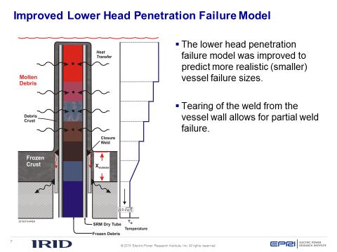
6 Relevant Models in MAAP 5.04 and Results When No Water is Added Improved treatment of corium behavior in lower plenum Addition of an important vessel penetration model that results in reducing the time to vessel failure 6
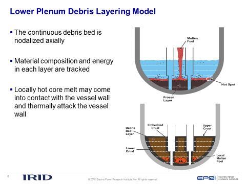
7 Principal Features of Lower Plenum Modeling Corium relocation to water in LP Particle bed generation from corium melt jet breakup Corium structure formation of oxide pool, crusts, and metal layer Heat transfer within corium pool and between corium and its surroundings Quenching debris bed In-vessel gap formation and cooling from gap Reactor vessel failure mechanisms 7

8 MAAP 5.04 Paints a Different Picture Of Corium Behavior in LP and Failure at Penetrations than Previous Codes Instrument tubes fill with molten core debris in core region. Molten debris re-freezes in instrument tubes and plugs form, particularly at the penetration locations. After relocation into the LP, instant stratification into a particle bed over metal and oxidic layers no longer assumed, but is calculated. The effect is to diminish the size and role of the metal layer. Earlier vessel failure predicted due to failure of closure welds from transfer of heat in the plugs. Consequently, in-vessel recovery may be less likely if water is added. 8
9 Failure mechanisms evaluated for initial failure of RPV lower head CRLH - damage fraction due to creep of the lower head wall CRCRD - damage fraction due to creep of ex-vessel CRD tube TRPTN - debris plug melt-through of instrument tubes at vessel weld: heat is transferred from plug to weld. EJPT - ejection of instrument tubes from weld failure EJCRD - of CRD tubes from weld failure EJDR - of drain line from weld failure ABLH - jet ablation of the lower head OVLH - overlying metal layer attacking the vessel wall 9
 Note that the other penetration")
10 Progression of RCS Failure Models Added in MAAP 4 through MAAP (Note: while the illustration is for BWRs, the models also apply to PWRs) Note that the other penetration failure models are also included in MAAP
11 Results from Simulating Mark I No Water Addition Cases Industry FLEX and (BWROG) EPG/SAG Rev. 3+ are assumed to be followed. Depressurizing RPV after RCIC failure makes in-vessel injection of fire water possible. Time is available after RCIC failure for injection into RPV to possibly prevent vessel failure. MELCOR 2.1 vessel failure due to lower head creep rupture. MAAP 5.03 vessel failure due to CRD tube ejection. MAAP 5.04 predicts earlier vessel failure (at 17.8 hr), at lower head penetrations due to weld failure. If penetration failure models bypassed, vessel fails by creep rupture at 19.2 hr. MELCOR 2.1 and MAAP 5.03 predict venting before vessel failure and consequent early iodine and cesium releases to the suppression pool and the environment. MAAP 5.04 releases to environment don t start until venting begins. Event Timing (hr) MELCOR 2.1 MAAP 5.03 MAAP 5.04 RCIC fails Core uncovers Core damage begins Lower head dries out Containment vented at 75 psia Vessel fails I release fraction to env. at 72 hr 2.3 E E E-2 Cs release fraction to env. at 72 hr 1.9 E E E-3 Hydrogen produced in vessel, kg
12 MAAP 5.03 and 5.04 Pictures of Melt Progression and Debris Evolution (no water addition) MAAP 5.03 Significant molten pool formed in core region, with surrounding crusts. Axial flow through molten pool blocked by crusts. Particulate debris, caused by jet breakup of molten pour, in lower plenum predominates at first, with rapid formation of molten metal and oxidic layers below the particle bed. Oxidic crust separates the molten layers. Vessel failure at 25 hr from ejection of CRD tubes penetrating part-way up the lower head. MAAP 5.04 Smaller molten pool formed in core region than for MAAP Particulate debris, caused by jet breakup of molten pour, aggregates in lower plenum. Particulate debris melts to form an oxidic pool, much crust, and a very small metallic layer. Vessel failure at 17.8 hr from instrument tube weld failure at the bottom of the lower head. 12

13 PB No Injection, Vessel Damage Fractions (MAAP 5.04 Case) Welds at instrument tube penetrations fail due to heat transfer from internal corium plugs where the tubes penetrate the vessel. Damage fractions increase rapidly at first; then increase gradually. CRD and drain line ejection penetration fractions are somewhat lower by vessel failure. RPV lower head creep damage fraction is still quite low at vessel failure. 13
14 IN-VESSEL RECOVERY 14
15 Benefits of Preventing Vessel Failure by Water Addition to RPV Averts drywell liner melt-through and other containment failure modes. No fission products or hydrogen in the reactor building If water is added soon enough, relocation of the corium into the lower plenum may not occur Nearly all volatile fission products are deposited either in the suppression pool or the RPV. Less than 1% are vented to the environment, and only after the vent is opened The sooner water is added the lower the releases The best outcome is to be able to add water before venting All lower-volatility fission products remain in the RPV Post-accident cleanup and maintenance of a safe stable state is much easier Long-term cooling by using the RHR system No debris in the pedestal region or drywell 15
16 CsI Distribution at 72 hr (MAAP 5.04) Releases to environment don t start until venting begins. Water addition suppresses revaporization and releases from RPV. Time RPV injection begins, hr Vessel Failure Fraction of CsI Inventory at 72 hr RPV DW SP Env. 13 No E E-5 14 No E E-4 15 Yes (late) E E-3 24 Yes E E-3 none Yes E E-3 16
17 No vessel failure following injection into RPV at 14.5 hr (MAAP 5.04) 17
18 Vessel Fails Following Injection into RPV at 15 hr (MAAP 5.04) Injection occurred while water was still in LP. Vessel failure delayed until 29.3 hr Weld failure from heat transfer from plugged tube at bottom of vessel 18
19 Ex-Vessel Mitigation and Achievement of a Safe Stable State 19
20 Debris Cooling in Mark I Pedestal Region following Injection into RPV just after Vessel Failure (MAAP 5.04) 20
21 Delayed Injection is Better Than No Injection at All (MAAP 5.03) 21
22 BWR Mark III Containment and Shield Building Perry and River Bend have steel containments inside annular shield buildings. Grand Gulf and Clinton have reinforced concrete containments inside annular shield buildings. All four containments have hydrogen igniters throughout. The design pressure is 15 psig for each plant. Grand Gulf has a vent that can be used to prolong RCIC until it fails, and then again after core damage. The others don t. DW and WW communicate only if the pressure difference between them is large enough to uncover at least one horizontal vent. If the SP water level gets high enough it can flow over the weir wall into the DW (and vice-versa). 22
23 Results for Perry Cases with No Recovery Pressurization after vessel failure is dominated by non-condensable gas generation from core debris/concrete interactions. Containment failure is assumed at 64.3 psig (the median composite failure pressure in the Perry IPE), at the equipment hatch level above the suppression pool (Comp. A). Containment survives more than a day. Small hydrogen burns early in scenarios. 23
24 Results and Insights for Grand Gulf No Recovery Cases The GGNS FLEX Integrated Plan states that igniters can be re-powered using a portable hydrogen igniter generator. There is no burning in the 12 hr battery cases. The no dc power and 12 hour battery cases, respectively, have practically identical pressure behavior. 24
25 Grand Gulf 12 hr Battery Cases: Oxygen Concentration in Upper Dome The main purpose of early venting is to prolong RCIC operation. In addition, early venting significantly lowers oxygen concentration, thus eliminating the possibility of Hydrogen and Carbon Monoxide burning later. Is not so effective when the batteries fail early. 25
26 PNPP RECOVERY STUDY Recovering diesel/ac power allows a number of actions to be taken Turning on RHR to cool suppression pool Using HPCS to add water to vessel and cool debris either in-vessel or in the Pedestal region Activate the Suppression Pool Make-Up system to initiate upper pool dump Vent the containment to lower pressure and remove hydrogen from the containment atmosphere Global burns are an issue to be dealt with after initiating recovery actions Recovery makes it possible to achieve a safe stable state 26
27 PNPP Recovery Study: Batteries Lost at 6 hr; Vary Time When RHR and 500 gpm HPCS are turned on after diesel generator is available Recovery of RHR cools down the suppression pool and the containment, and condenses steam. HPCS is somewhat effective in limiting CCI and consequent Hydrogen and CO production. Large global hydrogen and CO burns are predicted in the dome after recovery. 27
28 Attributes of a Safe Stable State Low pressure in containment Water in suppression pool is cool and plentiful Sufficient water in Pedestal and Drywell to cool debris and terminate core debris/concrete interactions No flammable mixture of hydrogen and oxygen Core melt progression has stopped Radioactive releases have stopped 28
29 A Perry Safe Stable State Case: Containment Pressure Operator actions and events assumed are: diesel power and venting at 18 hr, upper pool dump at 19 hr, RHR, 500 gpm HPCS, igniters on at 20 hr, and 100 gpm SP make-up at 24 hr. Drywell pressure rises quickly following TIP tube failure at 10 hr and vessel failure at 17.1 hr. Containment pressure decreases to ambient after venting. 29
30 A Perry Safe Stable State Case: Containment Temperatures Operator actions and events assumed are: diesel power and venting at 18 hr, upper pool dump at 19 hr, RHR, 500 gpm HPCS, and igniters on at 20 hr, and 100 gpm SP make-up at 24 hr. Drywell temperatures are high because of persistent decay heat in core debris. Spikes are due to TIP tube failure at 10 hr and vessel failure at 17.1 hr. SP water and containment dome temperatures are low by 48 hr. 30
31 Perry Safe Stable State Determination: Hydrogen Production Recovery provides sufficient water onto the core debris to terminate hydrogen production and CCI. Earlier recovery significantly reduces hydrogen production from CCI. Venting as soon as possible after recovery further reduces hydrogen production from CCI. 31
32 Conclusions and Insights Early controlled venting enables RCIC to run longer, and delay core damage. Early venting in Mark III containments can diminish oxygen concentrations in containment, lowering the likelihood of hydrogen combustion later. Depressurizing RPV after RCIC failure makes in-vessel injection of fire water possible. Time is available after RCIC failure for injection into RPV to possibly prevent vessel failure. MAAP 5.04 predicts earlier vessel failure than MELCOR 2.1 and MAAP Most likely vessel failure mode is instrument tube ejection due to closure weld failure weld failure. 32
33 Conclusions and Insights (cont.) Fission product releases to environment don t start until venting begins. Water addition suppresses volatile fission product revaporization and releases from RPV. Water addition into the pedestal or lower drywell, from either the failed vessel or directly onto the corium, is very effective in limiting concrete ablation and combustible gas production. Venting is an important mitigation action, even for Mark III containments. For Mark III s it is important to vent after ac power is restored, and to wait awhile to turn igniters back on. 33
34 Backup Slides 34

35 Debris Bed Arrangement in Lower Plenum. 35

36 Quenching by Water Ingression to Debris Bed. 36
37 37
38 38
39 Molten Pool Mass in Core Region for Various Injection Times (MAAP 5.03) 39
40 Recovery from Injection into RPV at 20 hr: Corium and Water in LP (MAAP 5.03) MAAP 5.03 predicts that recovery is still possible even if most of the corium is in the LP and the LP has dried out. RCIC is assumed to fail at 9.6 hr, so more than 10 hr is available to begin injection to prevent vessel failure. 40
41 Debris Cooling in Mark I Pedestal Region following Injection into RPV just after Vessel Failure (MAAP 5.03) 41
42 PNPP Recovery Study: Batteries Lost at 6 hr, RHR and HPCS on at 24 hr: HPCS flow rate variations Flow rates for W sat are gpm. Significantly more energy is removed than what is produced by decay heat. However, steam condensation causes the containment to be deinerted and a global burn results, failing the containment. A flow rate of 500 gpm easily removes the decay heat. However, a global burn results. Flow rates for W vap are gpm. Energy from the decay heat is removed, and no global burns occur. Pressure remains elevated, however. 50 gpm is insufficient to remove all the decay heat, The containment fails from overpressure. 42
43 PNPP Recovery Study: Batteries Lost at 6 hr, RHR and 500 gpm HPCS, No Igniters Even with no igniters, global burns calculated to occur when containment is de-inerted. and ignition criteria are met, even if igniters are not energized. Suppression pool temperatures reduced to about 110 ºF from RHR cooling. Sufficient water added to Pedestal and Drywell to cool core debris. 43
44 PNPP Recovery Study: RHR and 500 gpm HPCS at 24 hr Global Burn in Upper Dome at 65.7 hr Global Hydrogen (and Carbon Monoxide) burns are predicted when Oxygen concentration in the dome increases while steam condenses. Once de-inerting is achieved, igniters provide the sparks. CO and Nitrogen are not shown. CO behaves like Hydrogen, while Nitrogen is an inertant like steam. 44
45 Upper Dome and Drywell Pressures at Time of Global Burn Pressure rise in Drywell lags that in the containment dome (where the burn originates). This leads to an implosive pressure load on the drywell Suppression pool bypass is unlikely because the pressure differential between the Drywell and Wetwell is less than 30 psid and the likelihood of a stuck-open vacuum breaker is very low. 45
46 Perry Safe Stable State Determination: Hydrogen Production Recovery provides sufficient water onto the core debris to terminate hydrogen production and CCI. Earlier recovery significantly reduces hydrogen production from CCI. Venting as soon as possible after recovery further reduces hydrogen production from CCI. 46
47 Perry Safe Stable State Determination: Cesium Release Fraction Fission product releases reduced from no-recovery case results. 47
IAEA Training in Level 2 PSA MODULE 8: Coupling Source Terms to Probabilistic Event Analysis (CET end-state binning)
") IAEA Training in Level 2 PSA MODULE 8: Coupling Source Terms to Probabilistic Event Analysis (CET end-state binning) The Problem A probabilistic treatment of severe accident progression leads to numerous
IAEA Training in Level 2 PSA MODULE 8: Coupling Source Terms to Probabilistic Event Analysis (CET end-state binning) The Problem A probabilistic treatment of severe accident progression leads to numerous
REGULATORY OBSERVATION
 RO unique no.: REGULATORY OBSERVATION REGULATOR TO COMPLETE RO-ABWR-0046 Date sent: 20 th April 2015 Acknowledgement required by: 08 th May 2015 Agreement of Resolution Plan required by: 14 th May 2015
Extensive Damage Mitigation Guidelines (EDMG)
") Extensive Damage Mitigation Guidelines (EDMG) Roy Harter RLH Global Services Regional Workshop on Sharing Best Practices in Development and Implementation of Severe Accident Management Guidelines October
Extensive Damage Mitigation Guidelines (EDMG) Roy Harter RLH Global Services Regional Workshop on Sharing Best Practices in Development and Implementation of Severe Accident Management Guidelines October
IEM on Severe Accident Management in the light of the accident at the Fukushima Daïchi NPP
 IEM on Severe Accident Management in the light of the accident at the Fukushima Daïchi NPP Progress, challenges and perspectives in the field of design features, as regards SAMG IAEA, March 2014 Introduction
Classical Event Tree Analysis and Dynamic Event Tree Analysis for High Pressure Core Melt Accidents in a German PWR
 OECD International Workshop on Level 2 PSA and Severe Accident Management Koeln, Germany, March 29-31, 2004 Classical Event Tree Analysis and Dynamic Event Tree Analysis for High Pressure Core Melt Accidents
Integrated Coping Strategies for Beyond-Design-Basis External Events
 IAEA IEM on SAM in the Light of the Fukushima Daiichi NPP, 17-20 March 2014, Vienna, Austria Integrated Coping Strategies for Beyond-Design-Basis External Events Jaewhan Kim and Kwang-Il Ahn KAERI Contents
Nuclear safety Lecture 4. The accident of the TMI-2 (1979)
") Nuclear safety Lecture 4. The accident of the TMI-2 (1979) Ildikó Boros BME NTI 27 February 2017 The China Syndrome Opening: 16 March 1979 Story: the operator of the Ventana NPP tries to hide the safety
Nuclear safety Lecture 4. The accident of the TMI-2 (1979) Ildikó Boros BME NTI 27 February 2017 The China Syndrome Opening: 16 March 1979 Story: the operator of the Ventana NPP tries to hide the safety
DETAILS OF THE ACCIDENT PROGRESSION IN 1F1
 DETAILS OF THE ACCIDENT PROGRESSION IN 1F1 EMUG 2019 BRAUN, Matthias Switzerland, 3 rd -5 th April 2019 Not part of the BSAF OECD Benchmark Project Relying exclusively on publically available input data
FUNDAMENTAL SAFETY OVERVIEW VOLUME 2: DESIGN AND SAFETY CHAPTER F: CONTAINMENT AND SAFEGUARD SYSTEMS 7. CONTAINMENT HEAT REMOVAL SYSTEM (EVU [CHRS])
![FUNDAMENTAL SAFETY OVERVIEW VOLUME 2: DESIGN AND SAFETY CHAPTER F: CONTAINMENT AND SAFEGUARD SYSTEMS 7. CONTAINMENT HEAT REMOVAL SYSTEM (EVU [CHRS])](/thumbs/78/77361990.jpg "FUNDAMENTAL SAFETY OVERVIEW VOLUME 2: DESIGN AND SAFETY CHAPTER F: CONTAINMENT AND SAFEGUARD SYSTEMS 7. CONTAINMENT HEAT REMOVAL SYSTEM (EVU [CHRS])") PAGE : 1 / 16 7. CONTAINMENT HEAT REMOVAL SYSTEM (EVU [CHRS]) 7.0. SAFETY REQUIREMENTS 7.0.1. Safety functions The main functions of the EVU system [CHRS] are to limit the pressure inside the containment
PAGE : 1 / 16 7. CONTAINMENT HEAT REMOVAL SYSTEM (EVU [CHRS]) 7.0. SAFETY REQUIREMENTS 7.0.1. Safety functions The main functions of the EVU system [CHRS] are to limit the pressure inside the containment
Comparison of the partner s approaches for physical phenomena assessment in level 2 PSA
 1/11 Comparison of the partner s approaches for physical phenomena assessment in level 2 PSA J. Eyink, Framatome ANP; H. Löffler, GRS Cologne Abstract Aim of the task 5.1 of the SARNET PSA2 work package
COMPUTING SOURCE TERMS WITH DYNAMIC CONTAINMENT EVENT TREES
 COMPUTING SOURCE TERMS WITH DYNAMIC CONTAINMENT EVENT TREES Tero Tyrväinen 1, Taneli Silvonen 2, Teemu Mätäsniemi 1 1 VTT Technical Research Centre of Finland Ltd.: P.O. Box 1000, Espoo, Finland, 02044,
ASVAD THE SIMPLE ANSWER TO A SERIOUS PROBLEM. Automatic Safety Valve for Accumulator Depressurization. (p.p.)
") ASVAD Automatic Safety Valve for Accumulator Depressurization (p.p.) THE SIMPLE ANSWER TO A SERIOUS PROBLEM International Experts Meeting on Strengthening Research and Development Effectiveness in the
ASVAD Automatic Safety Valve for Accumulator Depressurization (p.p.) THE SIMPLE ANSWER TO A SERIOUS PROBLEM International Experts Meeting on Strengthening Research and Development Effectiveness in the
TEPCO s Safety Assurance Philosophy on Nuclear Power Generation Plants
 TEPCO s Safety Assurance Philosophy on Nuclear Power Generation Plants January 25, 2013 Tokyo Electric Power Company, Inc. This English translation has been prepared with the intention of creating an accurate
IAEA SAFETY STANDARDS for protecting people and the environment
 IAEA SAFETY STANDARDS for protecting people and the environment DESIGN OF REACTOR CONTAINMENT STRUCTURE AND SYSTEMS FOR NUCLEAR POWER PLANTS DRAFT SAFETY GUIDE DS 482 STATUS: STEP 11 Submission to Review
Instrumentation systems of BWR
 Instrumentation systems of BWR 1 Reactor core and pressure vessel of BWR Fuel rod Fuel assembly Reactor vessel :15~22cm thickness of steel, height of 21m, diameter of 7m Steam dryer Pressure vessel Main
Verification and validation of computer codes Exercise
 IAEA Safety Assessment Education and Training (SAET) Programme Joint ICTP- IAEA Essential Knowledge Workshop on Deterministic Safety Assessment and Engineering Aspects Important to Safety Verification
IAEA SAFETY STANDARDS for protecting people and the environment
 Date: 2016-08-31 IAEA SAFETY STANDARDS for protecting people and the environment STATUS: STEP 8a For Submission to Member States DESIGN OF REACTOR CONTAINMENT STRUCTURE AND SYSTEMS FOR NUCLEAR POWER PLANTS
Level 2 PSA for the VVER 440/213 Dukovany Nuclear Power Plant
 Nuclear Nuclear Research Research Institute Řež plc Institute Řež plc Level 2 PSA for the VVER 440/213 Dukovany Nuclear Power Plant Jiří Dienstbier, Stanislav Husťák OECD International Workshop on Level-2
Loss of Normal Feedwater Analysis by RELAP5/MOD3.3 in Support to Human Reliability Analysis
 Loss of Normal Feedwater Analysis by RELAP5/MOD3.3 in Support to Human Reliability Analysis ABSTRACT Andrej Prošek, Borut Mavko Jožef Stefan Institute Jamova cesta 39, SI-1 Ljubljana, Slovenia Andrej.Prosek@ijs.si,
DESIGN OF REACTOR CONTAINMENT STRUCTURE AND SYSTEMS FOR NUCLEAR POWER PLANTS
 SAFETY STANDARDS SERIES No. NS-G-1.10 DESIGN OF REACTOR CONTAINMENT STRUCTURE AND SYSTEMS FOR NUCLEAR POWER PLANTS SAFETY GUIDE DS 482 2016-04-20 INTERNATIONAL ATOMIC ENERGY AGENCY VIENNA, C-41 (May 13)
XA TEPSS RELATED PANDA TESTS (ESBWR)
") TEPSS RELATED PANDA TESTS (ESBWR) XA0055019 M. HUGGENBERGER, C. AUBERT, T. BANDURSKI, J. DREIER, O. FISCHER, HJ. STRASSBERGER Thermal-Hydraulics Laboratory, Paul Scherrer Institute, Villigen G. YADIGAROGLU
TEPSS RELATED PANDA TESTS (ESBWR) XA0055019 M. HUGGENBERGER, C. AUBERT, T. BANDURSKI, J. DREIER, O. FISCHER, HJ. STRASSBERGER Thermal-Hydraulics Laboratory, Paul Scherrer Institute, Villigen G. YADIGAROGLU
THE NITROGEN INJECTION THREAT IN PWR REACTORS
 THE NITROGEN INJECTION THREAT IN PWR REACTORS Weakness of current strategies & ASVAD, the new passive solution. Arnaldo Laborda Rami ASVAD INTL. SL (SPAIN) Tarragona (SPAIN) Email: alaborda@asvad-nuclear.com
DESIGN OF REACTOR CONTAINMENT STRUCTURE AND SYSTEMS FOR NUCLEAR POWER PLANTS
 SAFETY STANDARDS SERIES No. NS-G-1.10 DESIGN OF REACTOR CONTAINMENT STRUCTURE AND SYSTEMS FOR NUCLEAR POWER PLANTS SAFETY GUIDE DS 482 2016-04-20 INTERNATIONAL ATOMIC ENERGY AGENCY VIENNA, C-41 (May 13)
DDnmm,-- SEP U. S. Nuclear Regulatory Commission Attn.: Document Control Desk Mail Stop OP1-17 Washington, D. C
 SEP 0 5 2001 George T. Jones Vice President Nuclear Engineering & Support PPL Susquehanna, LLC Two North Ninth Street Allentown, PA 18101-1179 Tel. 610.774.7602 Fax 610.774.7797 gtjones@pplweb.com DDnmm,--
ICONE ASSESSMENT OF THE TRACE REACTOR ANALYSIS CODE AGAINST SELECTED PANDA TRANSIENT DATA
 Proceedings of ICONE : TH International Conference on Nuclear Engineering Miami, FL, USA, July -0, 00 ICONE- ASSESSMENT OF THE REACTOR ANALYSIS CODE AGAINST SELECTED PANDA TRANSIENT DATA M. Zavisca, M.
ON TRANSIENTS IN PUMA
 5 BNL-NUREG- 63 007 P, : EVALUATION OF THE EFFECTS OF INITIAL CONDITIONS ON TRANSIENTS IN PUMA Yiiksel Parlatan, Jae Jo, and Upendra S. Rohatgi Brookhaven National Laboratory Department of Advanced Technology
The Nitrogen Threat. The simple answer to a serious problem. 1. Why nitrogen is a risky threat to our reactors? 2. Current strategies to deal with it.
 International Conference on Topical Issues in Nuclear Installation Safety: Safety Demonstration of Advanced Water Cooled Nuclear Power Plants. The simple answer to a serious problem Vienna. 6 9 June 2017
Evaluation of the fraction of Unit-3 vent gas that flowed into Unit-4 reactor building
 Attachment 3-1 Evaluation of the fraction of Unit-3 vent gas that flowed into Unit-4 reactor building 1. Introduction The hydrogen explosion, which occurred on March 15, 211, at the Unit-4 reactor building
V.H. Sanchez Espinoza and I. Gómez-García-Toraño
 V.H. Sanchez Espinoza and I. Gómez-García-Toraño ANALYSIS OF PWR SEVERE ACCIDENT SEQUENCES INCLUDING MITIGATIVE MEASURES TO PREVENT OR DELAY THE FAILURE OF SAFETY BARRIERS WITH THE SEVERE ACCIDENT CODE
The «practical elimination» approach for pressurized water reactors
 The «practical elimination» approach for pressurized water reactors V. TIBERI K.HERVIOU International Conference on Topical Issues in Nuclear Installation Safety: Safety Demonstration of Advanced Water
Transient Analyses In Relief Systems
 Transient Analyses In Relief Systems Dirk Deboer, Brady Haneman and Quoc-Khanh Tran Kaiser Engineers Pty Ltd ABSTRACT Analyses of pressure relief systems are concerned with transient process disturbances
Severe Accident Management Programmes for Nuclear Power Plants
 DS 483: Mode 2 27 March 2017 IAEA SAFETY STANDARDS for protecting people and the environment STEP 11: Approval by the relevant review Committees Reviewed in NSOC (Asfaw) Severe Accident Management Programmes
Dynamic Context Quantification for Design Basis Accidents List Extension and Timely Severe Accident Management
 Dynamic Context Quantification for Design Basis Accidents List Extension and Timely Severe Accident Management Emil Kostov a,b and Gueorgui Petkov a a Technical University, Sofia, Bulgaria b WorleyParsons,
TOPIC: KNOWLEDGE: K1.01 [2.5/2.7] An atmospheric pressure of 15.0 psia is equivalent to... A psig. B psig. C psig.
![TOPIC: KNOWLEDGE: K1.01 [2.5/2.7] An atmospheric pressure of 15.0 psia is equivalent to... A psig. B psig. C psig.](/thumbs/89/99436374.jpg "TOPIC: KNOWLEDGE: K1.01 [2.5/2.7] An atmospheric pressure of 15.0 psia is equivalent to... A psig. B psig. C psig.") P73 An atmospheric pressure of 15.0 psia is equivalent to... A. 30.0 psig. B. 29.4 psig. C. 14.7 psig. D. 0.0 psig. ANSWER: D. P273 A pressure gauge on a condenser reads 27.0 inches Hg vacuum. What is
P73 An atmospheric pressure of 15.0 psia is equivalent to... A. 30.0 psig. B. 29.4 psig. C. 14.7 psig. D. 0.0 psig. ANSWER: D. P273 A pressure gauge on a condenser reads 27.0 inches Hg vacuum. What is
SAFETY MANUAL PURGING, VENTING & DRAINING PROCEDURE TABLE OF CONTENTS 1. INTRODUCTION SCOPE DEFINITIONS PROCEDURE...
 Page 1 of 11 TABLE OF CONTENTS 1. INTRODUCTION... 2 2. SCOPE... 2 3. DEFINITIONS... 2 4.... 3 5. RESPONSIBILTIES... 10 6. REFERENCES... 10 7. ATTACHMENTS... 11 8. APPENDICES... 11 Rev. Issue Date Amendment
ACCIDENT MANAGEMENT AND EPR AT DUKOVANY NPP
 ACCIDENT MANAGEMENT AND EPR AT DUKOVANY NPP 27-29 September 2017 Vienna IAEA Miroslav Trnka OVERVIEW General EOPs and SAMGs (changes) DAM (FLEX) EDMG Equipment (new + ongoing projects) Staff (drills and
FUNDAMENTAL SAFETY OVERVIEW VOLUME 2: DESIGN AND SAFETY CHAPTER P: REFERENCE OPERATING CONDITION STUDIES (PCC)
") PAGE : 1 / 11 1. PASSIVE SINGLE FAILURE ANALYSIS The aim of the accident analysis in Chapter P is to demonstrate that the safety objectives have been fully achieved, despite the most adverse single failure.
PAGE : 1 / 11 1. PASSIVE SINGLE FAILURE ANALYSIS The aim of the accident analysis in Chapter P is to demonstrate that the safety objectives have been fully achieved, despite the most adverse single failure.
Inspection Credit for PWSCC Mitigation via Peening Surface Stress Improvement
 Inspection Credit for PWSCC Mitigation via Peening Surface Stress Improvement Glenn A. White, Kyle P. Schmitt, Kevin J. Fuhr, Markus Burkardt, and Jeffrey A. Gorman Dominion Engineering, Inc. Paul Crooker
PRA Methodology Overview
 PRA Methodology Overview 22.39 Elements of Reactor Design, Operations, and Safety Lecture 9 Fall 2006 George E. Apostolakis Massachusetts Institute of Technology Department of Nuclear Science and Engineering
HTR Systems and Components
 IAEA Course on HTR Technology Beijing, 22-26.October 2012 HTR Systems and Components Dr. Gerd Brinkmann Dieter Vanvor AREVA NP GMBH Henry-Dunant-Strasse 50 91058 Erlangen phone +49 9131 900 96840/95821
ANNEX AMENDMENTS TO THE INTERNATIONAL CODE FOR FIRE SAFETY SYSTEMS (FSS CODE) CHAPTER 15 INERT GAS SYSTEMS
 CHAPTER 15 INERT GAS SYSTEMS") Annex 3, page 2 ANNEX AMENDMENTS TO THE INTERNATIONAL CODE FOR FIRE SAFETY SYSTEMS (FSS CODE) CHAPTER 15 INERT GAS SYSTEMS The text of existing chapter 15 is replaced by the following: "1 Application This
Annex 3, page 2 ANNEX AMENDMENTS TO THE INTERNATIONAL CODE FOR FIRE SAFETY SYSTEMS (FSS CODE) CHAPTER 15 INERT GAS SYSTEMS The text of existing chapter 15 is replaced by the following: "1 Application This
INHERENTLY SAFER DESIGN CASE STUDY OF RAPID BLOW DOWN ON OFFSHORE PLATFORM
 INHERENTLY SAFER DESIGN CASE STUDY OF RAPID BLOW DOWN ON OFFSHORE PLATFORM Volton Edwards bptt Angus Lyon DNV Energy Alastair Bird DNV Energy INTRODUCTION A term now in common usage within the oil & gas
Engineering & Projects Organization
 Engineering & Projects Organization Note from : Date: 11/09/2012 To : Copy : N : PEPR-F.10.1665 Rev. 3 Subject: EPR UK - GDA GDA issue FS04 Single Tube Steam Generator Tube Rupture Analysis for the UK
Absorption - The process of contacting a vapor and gas stream with an absorbing liquid to remove specific materials from the gas stream.
 Sufe Design and Optvation ofpi-oc.ess Vents and Emission Contid $wteins by Center for Chemical Process Safety Copyright 0 2006 John Wiley & Sons, Tnc. APPENDIX B GLOSSARY Absorption - The process of contacting
Unit 2 Primary Containment Vessel Internal Investigation
 Unit 2 Primary Containment Vessel Internal Investigation December 21, 2017 Tokyo Electric Power Company Holdings, Inc. 1. Conditions inside the Unit 2 Primary Containment Vessel According to accident development
Leaks from Unit-3 PCV and steam release in a large amount
 Attachment 3-8 Leaks from Unit-3 PCV and steam release in a large amount 1. Background At Unit-3 the suppression chamber (S/C) vent line configuration was completed at 08:41 on March 13 th and the dry
-. 30ýv. Entergy ARKANSAS NUCLEAR ONE - UNIT I IMPROVED TECHNICAL SPECIFICATIONS SUBMITTAL. 05/01101 Supplement Volume 2 of 2. (Sections 3.7 and 3.
 ARKANSAS NUCLEAR ONE - UNIT I IMPROVED TECHNICAL SPECIFICATIONS SUBMITTAL -. 30ýv May 1, 2001 05/01101 Supplement Volume 2 of 2 (Sections 3.7 and 3.8) Entergy MSSVs 3.7.1 3.7 PLANT SYSTEMS 3.7.1 Main Steam
BASIC OXYGEN FURNACES
 GAP.17.4.1 A Publication of Global Asset Protection Services LLC BASIC OXYGEN FURNACES INTRODUCTION Most steelmaking facilities use basic oxygen furnaces (BOFs) to produce molten steel. GAP.17.4.0 describes
MELCOR code application to VVER440/V213 analyses
 1 st Meeting of European MELCOR Users Group, MELCOR code application to VVER440/V213 analyses Villigen, Switzerland 15-16 December 2008 Juraj Jančovič jancovic@vuje.sk 1 CONTENT - overview of MELCOR models
Experimental Verification of Integrated Pressure Suppression Systems in Fusion Reactors at In-Vessel Loss-of -Coolant Events
 Experimental Verification of Integrated Pressure Suppression Systems in Fusion Reactors at In-Vessel Loss-of -Coolant Events K. Takase 1), H. Akimoto 1) 1) Japan Atomic Energy Research Institute (JAERI),
Considerations for the Practical Application of the Safety Requirements for Nuclear Power Plant Design
 Considerations for the Practical Application of the Safety Requirements for Nuclear Power Plant Design Joint ICTP-IAEA Essential Knowledge Workshop on Deterministic Safety Analysis and Engineering Aspects
Workshop Information IAEA Workshop
 IAEA Training Course on Safety Assessment of NPPs to Assist Decision Making Safety Assessment of General Design Aspects of NPPs (Part 2) Lecturer Lesson Lesson III III 1_2 1_2 Workshop Information IAEA
Ing. JOZEF BALÁŽ Ph.D. and Ing MILAN CVAN CSc
 PROPOSAL, DESIGN, IMPLEMENTATION AND SAFETY DEMONSTRATION OF SEVERE ACCIDENT MANAGEMENT MEASURES AT VVER440 IN SLOVAKIA Ing. Jozef Baláž, Ph.D. VUJE a.s. Trnava, Slovakia Email: Jozef.Balaz@vuje.sk Ing.
Review and Assessment of Engineering Factors
 Review and Assessment of Engineering Factors 2013 Learning Objectives After going through this presentation the participants are expected to be familiar with: Engineering factors as follows; Defense in
Safety and efficiency go hand in hand at MVM Paks NPP
 International Forum Atomexpo 2018 Safety and efficiency go hand in hand at MVM Paks NPP József Elter MVM Paks Nuclear Power Plant Ltd. Hungary Start up Four of the VVER-440/V213 unit Power units up-rate
Inerted Vessels: Preventing Hazards Caused by Gas Buoyancy
 Inerted Vessels: Preventing Hazards Caused by Gas Buoyancy 2008 Mary Kay O Connor O Process Safety Center International Symposium College Station, Texas Tuesday, October 28, 2008 presented by Russell A.
AP1000 European 19. Probabilistic Risk Assessment Design Control Document
 APPENDIX 19E SHUTDOWN EVALUATION 19E.1 Introduction Westinghouse has considered shutdown operations in the design of the A1000 nuclear power plant. The AP1000 defense-in-depth design philosophy to provide
Proposed Abstract for the 2011 Texas A&M Instrumentation Symposium for the Process Industries
 Proposed Abstract for the 2011 Texas A&M Instrumentation Symposium for the Process Industries Focus Area: Automation HMI Title: Author: Shared Field Instruments in SIS: Incidents Caused by Poor Design
FAILURE AND HAZARD ANALYSIS OF THE NPDGAMMA LH2 TARGET SYSTEM
 FAILURE AND HAZARD ANALYSIS OF THE NPDGAMMA LH2 TARGET SYSTEM Revision: 0.00 Edited by: Seppo Penttila, November 10, 2010 1. General The RSS 8305.0 Installation, Commissioning, and Operation of the NPDGamma
Event tree analysis. Prof. Enrico Zio. Politecnico di Milano Dipartimento di Energia. Prof. Enrico Zio
 Event tree analysis Politecnico di Milano Dipartimento di Energia Techniques for Risk Analysis Hazard identification: FMEA (Failure Modes and Effects Analysis) & HAZOP (HAZard and OPerability study) Accident
3 rd Year Design Module Scope
 LOSS PREVENTION & Process Safety PROCESS HAZARDS ANALYSIS -3 rd Year Design Module - 3 rd Year Design Module Scope Hazard Identification In the Process 1. Identify the major hazards that are present 2.
Simulation of Experiment on Aerosol Behaviour at Severe Accident Conditions in the LACE Experimental Facility with the ASTEC CPA Code
 Simulation of on Aerosol Behaviour at Severe Accident Conditions in the LACE al Facility with the CPA Code Ivo Kljenak, Borut Mavko Jožef Stefan Institute Jamova 39, SI-1000 Ljubljana, Slovenia Ivo.Kljenak@ijs.si,
Design and Safety Document for the Vacuum Windows of the NPDGamma Liquid Hydrogen Target at SNS
 Design and Safety Document for the Vacuum Windows of the NPDGamma Liquid Hydrogen Target at SNS Prepared: Checked: Approved: H. Nann W. Fox M. Snow The NPDGamma experiment is going to run at BL13 at SNS
An Improved Modeling Method for ISLOCA for RI-ISI and Other Risk Informed Applications
 An Improved odeling ethod for ISLOCA for RI-ISI and Other Risk Informed Applications Young G. Jo 1) 1) Southern Nuclear Operating Company, Birmingham, AL, USA ABSTRACT In this study, an improved modeling
SAFETY APPROACHES. The practical elimination approach of accident situations for water-cooled nuclear power reactors
 SAFETY APPROACHES The practical elimination approach of accident situations for water-cooled nuclear power reactors 2017 SUMMARY The implementation of the defence in depth principle and current regulations
Relief Systems. 11/6/ Fall
 Relief Systems 1 Relief Scenarios o A single relief event requires a particulate vent area and valve size o Relief scenarios are determined based on a PHA o For each scenario, a vent area is calculated
1 SE/P-02. Experimental and Analytical Studies on Thermal-Hydraulic Performance of a Vacuum Vessel Pressure Suppression System in ITER
 1 SE/P-2 Experimental and Analytical Studies on Thermal-Hydraulic Performance of a Vacuum Vessel Pressure Suppression System in ITER K. Takase 1), H. Akimoto 1) 1) Japan Atomic Energy Research Institute,
Optimizing Gas Supply for Industrial Lasers
 Optimizing Gas Supply for Industrial Lasers Laser cutting of metals and other materials has grown rapidly due to developments in laser power, advancements in CNC automation, and decreasing costs. The industrial
Exekon. Nuclear. ý C)C) ý. May 9, 2001 SVP U. S. Nuclear Regulatory Commission ATTN: Document Control Desk Washington, D.C.
C) ý. May 9, 2001 SVP U. S. Nuclear Regulatory Commission ATTN: Document Control Desk Washington, D.C.") Exelon Generation Ouad Cities Generating Station 22710 206th Avenue North Cordova, I L 61242-9740 Tel 309-654-2241 May 9, 2001 www.exelon corp.com Exekon. Nuclear SVP-01-059 U. S. Nuclear Regulatory Commission
Exelon Generation Ouad Cities Generating Station 22710 206th Avenue North Cordova, I L 61242-9740 Tel 309-654-2241 May 9, 2001 www.exelon corp.com Exekon. Nuclear SVP-01-059 U. S. Nuclear Regulatory Commission
FUNDAMENTAL SAFETY OVERVIEW VOLUME 2: DESIGN AND SAFETY CHAPTER I: AUXILIARY SYSTEMS. A high-capacity EBA system [CSVS] [main purge]
![FUNDAMENTAL SAFETY OVERVIEW VOLUME 2: DESIGN AND SAFETY CHAPTER I: AUXILIARY SYSTEMS. A high-capacity EBA system [CSVS] [main purge]](/thumbs/88/117664573.jpg "FUNDAMENTAL SAFETY OVERVIEW VOLUME 2: DESIGN AND SAFETY CHAPTER I: AUXILIARY SYSTEMS. A high-capacity EBA system [CSVS] [main purge]") PAGE : 1 / 9 5. CONTAINMENT PURGE (EBA [CSVS]) The Reactor Building purge system comprises the following: A high-capacity EBA system [CSVS] [main purge] A low-capacity EBA system [CSVS] [mini-purge] 5.1.
PAGE : 1 / 9 5. CONTAINMENT PURGE (EBA [CSVS]) The Reactor Building purge system comprises the following: A high-capacity EBA system [CSVS] [main purge] A low-capacity EBA system [CSVS] [mini-purge] 5.1.
EXPERIMENTAL SUPPORT OF THE BLEED AND FEED ACCIDENT MANAGEMENT MEASURES FOR VVER-440/213 TYPE REACTORS
 International Conference Nuclear Energy for New Europe 22 Kranjska Gora, Slovenia, September 9-12, 22 www.drustvo-js.si/gora22 EXPERIMENTAL SUPPORT OF THE BLEED AND FEED ACCIDENT MANAGEMENT MEASURES FOR
Tokyo Electric Power Company Holdings, Inc. November 30, 2017
 < R e f e r e n c e > Partial damage to temperature gauge cables for the Reactor Pressure Vessel (RPV) found during the Fukushima Daiichi NPS Unit 3 Primary Containment Vessel () internal investigation
Mechanical Seal Piping Plans
 Mechanical Seal Piping Plans Single Seals plans 01, 02, 11, 13, 14, 21, 23, 31, 32, 41 Dual Seals plans 52, 53A, 53B, 53C, 54 Quench Seals plans 62, 65 Gas Seals plans 72, 74, 75, 76 Mechanical Seal Piping
Containment Isolation system analysis and its contribution to level 2 PSA results in Doel 3 unit
 Containment Isolation system analysis and its contribution to level 2 PSA results in Doel 3 unit Marius LONTOS a*, Stanislas MITAILLÉ a, and Shizhen YU a, Jérémy BULLE a TRACTEBEL ENGIE, Brussels, Belgium
DISTRIBUTION LIST. Preliminary Safety Report Chapter 7 Safety Systems UK HPR1000 GDA. GNS Executive. GNS all staff. GNS and BRB all staff CGN EDF
 Rev: 000 Page: 2 / 82 DISTRIBUTION LIST Recipients GNS Executive GNS all staff Cross Box GNS and BRB all staff CGN EDF Regulators Public Rev: 000 Page: 3 / 82 SENSITIVE INFORMATION RECORD Section Number
Mooney * Noise Controller Installation, Operation, and Maintenance Manual
 GE Oil & Gas Mooney * Noise Controller Installation, Operation, and Maintenance Manual imagination at work Scope This manual provides instructions for installation, operation and maintenance of the Mooney
Practical Modelling & Hazard Assessment of LPG & LNG Spills
 Practical Modelling & Hazard Assessment of LPG & LNG Spills UKELG 3 rd April 2012 Tony Ennis Introduction Refrigerated or pressurised Release scenarios & release rate Vaporisation Gas dispersion Consequences
Passive BWR Integral LOCA Testing at the Karlstein Test Facility INKA
 assive BWR Integral LOCA Testing at the Karlstein Test Facility INKA Robert Drescher, Erlangen/Germany, Thomas Wagner, Karlstein am Main/Germany, and Stephan Leyer, Deggendorf/Germany I. Introduction Addresses
SENSITIVITY ANALYSIS OF THE FIRST CIRCUIT OF COLD CHANNEL PIPELINE RUPTURE SIZE FOR WWER 440/270 REACTOR
 PROCEEDINGS OF THE YEREVAN STATE UNIVERSITY Physical and Mathematical Sciences 216, 2, p. 57 62 P h y s i c s SENSITIVITY ANALYSIS OF THE FIRST CIRCUIT OF COLD CHANNEL PIPELINE RUPTURE SIZE FOR WWER 44/27
Digester Processes. 1. Raw Sludge Pumping System
 Digester Processes 1. Raw Sludge Pumping System Removes accumulated sludge from the primary clarifiers, pumped through 1 of 2 pipes either 150 or 200mm in diameter (Fig. 1.1). Fig 1.1 Pipes feeding Digesters
Identification and Screening of Scenarios for LOPA. Ken First Dow Chemical Company Midland, MI
 Identification and Screening of Scenarios for LOPA Ken First Dow Chemical Company Midland, MI 1 Layers of Protection Analysis (LOPA) LOPA is a semi-quantitative tool for analyzing and assessing risk. The
Mechanical Seal Piping Plans
 Mechanical Seal Piping Plans Single Seals plans 01, 02, 03, 11, 13, 14, 21, 23, 31, 32, 41 Dual Seals plans 52, 53A, 53B, 53C, 54, 55 Quench Seals plans 62, 65A, 65B, 66A, 66B Gas Seals plans 72, 74, 75,
DISTRIBUTION LIST. Preliminary Safety Report Chapter 19 Internal Hazards UK HPR1000 GDA. GNS Executive. GNS all staff. GNS and BRB all staff CGN EDF
 Rev: 000 Page: 2 / 20 DISTRIBUTION LIST Recipients GNS Executive GNS all staff Cross Box GNS and BRB all staff CGN EDF Regulators Public Rev: 000 Page: 3 / 20 SENSITIVE INFORMATION RECORD Section Number
I. CHEM. E. SYMPOSIUM SERIES No. 49
 HAZARDS OF HEATING IMMISCIBLE LIQUIDS R.B. Keey Department of Chemical Engineering, University of Canterbury, Christchurch, New Zealand. A recent incident at an oil re-refining plant in New Zealand highlighted
Large Scale BWR Containment LOCA Response Test at the INKA Test Facility
 Large Scale BWR Containment LOCA Response Test at the INKA Test Facility Thomas Wagner AREVA GmbH Seligenstädter Straße 100,63791 Karlstein, Germany thomas.wagner@areva.com Stephan Leyer FSTC Université
Technical Operating Instructions for Magnum Cutting Systems. for online instructions
 Technical Operating Instructions for Magnum Cutting Systems http://www.magnumusa.com/operating-video.html for online instructions In Case of Emergency Immediately Call for Medical Aid. Familiarize yourself
OPERATION. Estimated kerf width compensation. HPR260 Manual Gas Instruction Manual 4-9
 Estimated kerf width compensation The widths in the chart below are for reference. Differences between installations and material composition may cause the specific user results to vary from those shown
Summary of Safety and Environmental Assessment of ARIES-AT. David Petti Fusion Safety Program, INEEL
 Summary of Safety and Environmental Assessment of ARIES-AT David Petti Fusion Safety Program, INEEL Radiological Release Limits and Key In-Vessel Inventories Release limits to meet 1 Rem no-evacuation
NPSAG RAPPORT
 NPSAG RAPPORT 11-004-03 Evaluation of Existing Applications and Guidance on Methods for HRA EXAM-HRA HRA Application guide NPSAG Report 11-004-03 Gunnar Johanson, Sandra Jonsson 1 Kent Bladh, Tobias Iseland
Guidance on room integrity testing and its interpretation
 Guidance Note Guidance on room integrity testing and its interpretation Guidance on room integrity testing and its interpretation 1. SCOPE... 6 2. INTRODUCTION AND BACKGROUND... 6 2.1. DEVELOPMENT OF INTEGRITY
Permitted MSS Emissions Tracking, Recordkeeping, and Reporting. Presented by ACES April 24, 2008
 Permitted MSS Emissions Tracking, Recordkeeping, and Reporting Presented by ACES April 24, 2008 1 Agenda Introductions Overview of Current MSS Permitting Program Status Discussion of Model MSS Permit Requirements
Custom-Engineered Solutions for the Nuclear Power Industry from SOR
 Custom-Engineered Solutions for the Nuclear Power Industry from SOR As the world s aging nuclear power plants continue to be challenged with maintenance and Instrumentation Solutions for the Nuclear Power
SAFETY DEMONSTRATION TESTS ON HTR-10
 2nd International Topical Meeting on HIGH TEMPERATURE REACTOR TECHNOLOGY Beijing, CHINA,, September 22-24, 24 #Paper H6 SAFETY DEMONSTRATION TESTS ON HTR-1 Shouyin HU, Ruipian WANG, Zuying GAO Institute
MATERIAL SAFETY DATA SHEET
 MATERIAL SAFETY DATA SHEET Page: 1 of 5 1. CHEMICAL PRODUCT AND COMPANY IDENTIFICATION Identity (As Used on Label and List): SKF Grease LGMT 2 Product Code: LGMT 2 Product Use: Bearing lubricant Trade
Enhancing NPP Safety through an Effective Dependability Management
 Prepared and presented by Gheorghe VIERU, PhD Senior Scientific Nuclear Security Research Worker AREN/c.o. Institute for Nuclear Research Pitesti, ROMANIA Safety: Defence in Depth, October 2013 1 OUTLINES
August 31, CFR CFR ATTN: Document Control Desk U.S. Nuclear Regulatory Commission Washington, D.C.
 Tennessee Valley Authority 1101 Market Street, LP 3R Chattanooga, Tennessee 37402-2801 R. M. Krich Vice President Nuclear Licensing August 31, 2011 10 CFR 50.4 10 CFR 50.90 ATTN: Document Control Desk
A Computational Assessment of Gas Jets in a Bubbly Co-Flow 1
 A Computational Assessment of Gas Jets in a Bubbly Co-Flow 1 Melissa Fronzeo*, 1 Michael Kinzel 1 The Pennsylvania State University, University Park, PA, USA Abstract In this effort, Computational Fluid
Inert Air (N2) Systems Manual
 Systems Manual") INSTRUCTION MANUAL Inert Air (N2) Systems Manual N2-MANUAL 2.10 READ AND UNDERSTAND THIS MANUAL PRIOR TO OPERATING OR SERVICING THIS PRODUCT. GENERAL INFORMATION Positive pressure nitrogen gas pressurizing
INSTRUCTION MANUAL Inert Air (N2) Systems Manual N2-MANUAL 2.10 READ AND UNDERSTAND THIS MANUAL PRIOR TO OPERATING OR SERVICING THIS PRODUCT. GENERAL INFORMATION Positive pressure nitrogen gas pressurizing
SAFE DESIGN AND OPERATION OF CRYOGENIC ENCLOSURES
 SAFE DESIGN AND OPERATION OF CRYOGENIC ENCLOSURES AIGA 079/12 GLOBALLY HARMONISED DOCUMENT Asia Industrial Gases Association 3 HarbourFront Place, #09-04 HarbourFront Tower 2, Singapore 099254 Tel : +65
Technical Specification Bases Update to the NRC for Period Dated
 ...~Entergy Entergy Operations, Inc. 7003 Bald Hill Road PO. Box 756 Port Gibson, MS 39150 Tel 601 437 6299 Christina L. Perino Manager Licensing GNRO-2009/00017 March 4, 2009 U.S. Nudear Regulatory Commission