FLORIDA ROUNDABOUT GUIDE TABLE OF CONTENTS CHAPTER 1 - INTRODUCTION
|
|
|
- Stanley Willis
- 5 years ago
- Views:
Transcription
1
2 FLORIDA ROUNDABOUT GUIDE TABLE OF CONTENTS PAGE CHAPTER 1 - INTRODUCTION ROUNDABOUT CHARACTERISTICS SIGNIFICANT REFERENCE DOCUMENTS USE OF ROUNDABOUTS ORGANIZATION AND USE OF THIS GUIDE CHAPTER 2 - ROUNDABOUT JUSTIFICATION INTERSECTION CONTROL ALTERNATIVES CONTRAINDICATING FACTORS ROUNDABOUT JUSTIFICATION CATEGORIES Community Enhancement Traffic Calming Safety Improvement All Way Stop Control Alternative Low Volume Signal Alternative Medium Volume Signal Alternative Special Conditions COMMON DATA REQUIREMENTS ROUNDABOUT JUSTIFICATION PROCEDURE Step 1 - Obtain Common Data Step 2 - Identify Justification Category Step 3 - Obtain Data Requirements Specific to a Particular Category Step 4 - Perform Preliminary Geometric Design to Establish Feasibility Step 5 - Analyze the Performance of a Roundabout Step 6 - Analyze the Performance of Alternative Control Modes Step 7 - Assess Contraindications and Propose Mitigation Treatments Step 8 - Final Recommendation Roundabout Justification Study Summary and Report CHAPTER 3 - ROUNDABOUT PERFORMANCE ANALYSIS INTRODUCTION Control Alternatives Significant Reference Documents THEORY OF ROUNDABOUT OPERATION
3 Estimation of Capacity Estimation of Delay ROUNDABOUT MODELING BY SIDRA A Simple Example SIDRA Data Requirements COMPARISON OF RESULTS Single Lane Roundabouts Two-Lane Roundabouts Effect of Left Turns OTHER ANALYSIS MODELS FIELD EVALUATION OF ROUNDABOUT PERFORMANCE Traffic Volume Counts Delay Studies Safety Studies General Observations CLOSURE CHAPTER 4 - GEOMETRIC DESIGN OF ROUNDABOUTS DESIGN VEHICLE APPROACH AND ENTRY CHARACTERISTICS CENTRAL ISLAND CIRCULATING WIDTH INSCRIBED CIRCLE DIAMETER EXIT CURVES SPLITTER ISLANDS DEFLECTION Deflection at Roundabouts with One Circulating Lane Deflection at Roundabouts With Two or Three Circulating Lanes SIGHT DISTANCE REQUIREMENTS Stopping Sight Distance Gap Acceptance Sight Distance Other Visibility Considerations SUPERELEVATION AND DRAINAGE STREETS OF UNEQUAL WIDTH AND/OR WIDE MEDIANS ROUNDABOUTS AT "T" INTERSECTIONS PARKING BICYCLE AND PEDESTRIAN DESIGN CONSIDERATIONS SPECIAL CONSIDERATIONS ROUNDABOUTS ON LOCAL ROADS A TYPICAL ROUNDABOUT EXAMPLE
4 CHAPTER 5 - OPERATIONAL CONSIDERATIONS SIGNING Signing on the Approach Signing Within the Inscribed Circle PAVEMENT MARKINGS Yield Lines Splitter Islands and Approach Pavement Markings Within the Inscribed Circle Pedestrian And Bicycle Considerations LIGHTING LANDSCAPING Design Features Safety Issues Related to Landscaping Landscaping to Improve Roundabout Efficiency Community Enhancement Considerations GLOSSARY REFERENCES METRIC CONVERSION TABLE APPENDIX A - FLORIDA STATUTES GOVERNING OPERATION OF ROUNDABOUTS APPENDIX B - ROUNDABOUT JUSTIFICATION STUDY APPENDIX C - CASE STUDY FOR A SINGLE LANE ROUNDABOUT
5 LIST OF FIGURES FIGURES Page 1-1 Basic roundabout Effect of opposing volume on opposed movement capacity Performance comparison of control alternatives for the hypothetical 3-8 example 3-3 Lane configurations for signalized intersection alternatives Effect of left turns on roundabout and signal capacity Basic geometric elements of a roundabout Photograph of a typical roundabout Typical roundabout entrance, exit and splitter island geometric 4-5 configuration 4-4 Typical rural roundabout design Illustration of the deflection criteria for a single-lane roundabout Gap acceptance sight distance Roundabout with right turn bypass lane Minimum configuration for a simple roundabout 4-19
6 ACKNOWLEDGEMENTS The Florida Roundabout Guide was developed by the Florida Department of Transportation to assist district offices and local agencies in identifying appropriate site for roundabouts and determining their preferred configuration and operational features. The material contained in this guide reflects the recommended practice from countries in which roundabouts are popular, combined with the results of research on roundabout performance modeling and the consensus of a technical advisory committee on the optimal deployment of roundabouts in Florida. The development project was coordinated by the FDOT Offices of Traffic Engineering and Roadway Design. Research support was provided by the University of Florida Transportation Research Center. Members of the Technical Advisory Committee included: Lap Hoang, FDOT Office of Traffic Engineering (Chairman) Dave Blodgett, FDOT Planning Office Dan Burden, FDOT Safety Office Mark Doctor, FHWA Tom Hancock, FDOT Roadway Design Bob Higginbotham, FDOT Roadway Design Liang Hsia, FDOT Traffic Engineering Brian Kanely, City of Gainesville Traffic Engineer Henk Koornstra, Consulting Engineer Jim Mills, FDOT Roadway Design Tom Pridgen, District 1 FDOT, Traffic Operations Clark Scott, FDOT Roadway Design Freddie Vargas, District 4 FDOT, Traffic Operations Michael Wallwork, Consulting Engineer Technical and research support was provided by Kenneth G. Courage, Jeanne Wise and Sam Joseph, University of Florida Transportation Research Center, and Leif Ourston, Consultant. Cover photo courtesy of Dan Burden, FDOT Safety Office. March 1996
7 CHAPTER 1 INTRODUCTION In the interest of safety, the conflict between two competing traffic movements must be resolved by a traffic control discipline that gives one movement priority over the other. When both movements are heavy, the priority must be alternated or distributed in some manner or else one of the movements will fail. For high volume roadways, traffic signals provide the most common traffic control discipline in the U.S.A. because of the positive way in which the priority is alternated. Low volume roads are normally controlled by stop signs. Traffic circles have also been used to distribute priority. Traffic circles have many forms, but their common feature is that they are designed around a central island that prevents vehicles from passing through them on a linear path. For purposes of this document the definition of a traffic circle will be "any intersection of two or more streets that is designed around a central island." The basic principle of a traffic circle is to channelize the vehicle paths to disperse the conflicts that are concentrated at a conventional intersection and resolve each one in an appropriate manner. For example, Dupont Circle in Washington, DC employs a mixture of stop, yield and signal control in addition to weaving and a grade separation to resolve all of the conflicts that take place. Traffic circles, defined in the broad sense, are a somewhat controversial form of control that has its proponents and opponents around the world. Research conducted mostly in Europe and Australia has refined the general concept of a traffic circle into a form that has gained greater acceptance internationally. While completely consistent terminology has not yet evolved, the term "roundabout", or sometimes "modern roundabout" has generally been used in reference to this improved version of the traffic circle. This document presents a methodology for identifying appropriate roundabout sites and estimating roundabout capacity and delay. It describes the design principles and standards to which roundabouts installed on state roadways must conform and offers guidelines for operational features such as signing, marking, lighting, landscaping, etc. The term "roundabout" will be used to denote a subset of traffic circles that conform to the set of characteristics described below. These principles and standards have made roundabouts a safe and efficient form of intersection control in several countries including the U.S.A. 1.1 ROUNDABOUT CHARACTERISTICS Three main features are illustrated in Figure 1-1 which shows the basic layout of a roundabout. The roundabouts described in this guide are distinguished from traffic circles in general by a set of common characteristics. Traffic circles that do not exhibit these characteristics are not considered as roundabouts by FDOT. For comparison purposes the non-conforming features found at some 1-1
8
9 traffic circles are indicated in italics. The common characteristics that define a roundabout are as follows: Vehicles entering a roundabout on all approaches are required to yield to vehicles within the circulating roadway. Traffic circles sometimes employ stop or signal control or give priority to entering vehicles. The circulating vehicles are not subjected to any other right of way conflicts and weaving is kept to a minimum. This provides the means by which the priority is distributed and alternated among vehicles. A vehicle entering as a subordinate vehicle immediately becomes a priority vehicle until it exits the roundabout. Some traffic circles impose control measures within the circulating roadway, or are designed with weaving areas to resolve conflicts between movements. The speed at which a vehicle is able to negotiate the circulating roadway is controlled by the location of the central island with respect to the alignment of the right entry curb. This feature is responsible for the improved safety record of roundabouts. Some large traffic circles provide straight paths for major movements or are designed for higher speeds within the circulating roadway. Some small traffic circles do not achieve adequate deflection for speed control because of the small central island diameter. No parking is allowed on the circulating roadway. Parking maneuvers prevent the roundabout from operating in a manner consistent with its design. Some larger traffic circles permit parking within the circulating roadway. No pedestrian activities take place on the central island. Pedestrians are not intended to cross the circulating roadway. Some larger traffic circles provide for pedestrian crossing to, and activities on, the central island. All vehicles circulate counterclockwise, passing to the right of the central island. In some smaller traffic circles (sometimes called "mini-traffic circles") left-turning vehicles are expected to pass to the left of the central island. Roundabouts are designed to properly accommodate specified design vehicles. Chapter 4 provides more detail on this subject. Some smaller traffic circles are unable to accommodate large vehicles usually because of right of way constraints. Roundabouts have raised splitter islands (See Figure 1-1) on all approaches. See Chapter 4 for minimum dimensions. Splitter islands are an essential safety feature, required to separate traffic moving in opposite directions and to provide refuge for pedestrians. They are also an integral part of the deflection scheme. Some smaller traffic circles do not provide raised splitter islands. 1-3
10 When pedestrian crossings are provided for the approach roads, they are placed approximately one car length back from the entry point. Some traffic circles accommodate pedestrians in other places, such as the yield point. The entry deflection is the result of physical features of a roundabout. Some traffic circles rely on pavement markings to promote deflection. The construction of traffic circles on the state highway system that do not meet the standards contained in this guide or have characteristics that are not consistent with those of a roundabout is discouraged. While not explicit roundabout characteristics, the following features are necessary for a roundabout to perform safely and efficiently. They must be easily identified in the road system; The layout must be clearly visible and marked appropriately; The layout must encourage drivers to enter the intersection slowly; Adequate sight distance must be provided at all entry points to enable the driver to enter the intersection and to observe the movements of pedestrians and bicyclists; and Adequate lighting must be provided for safe operation at night. 1.2 SIGNIFICANT REFERENCE DOCUMENTS Because of the popularity of roundabouts in Australia and Europe, a large amount of literature on this subject has evolved. Fortunately, a number of documents also exist that have summarized the most significant information and incorporated it into a more concise form. Each of these documents contains some material on roundabouts that is beyond the scope of the guidelines presented here. The following documents have been identified as useful references on the subject of roundabout design and operations in general: Austroads Guide to Traffic Engineering Practice: Part 6, Roundabouts [1] contains the full set of guidelines that govern the design, evaluation and operation of roundabouts in Australia. The Geometric Design of Roundabouts [2] Published in Britain by Her Majesty's Stationery Office. Describes the British approach to the design of roundabouts. It provides a very detailed treatment of the effects of geometric elements on roundabout capacity. Use of Roundabouts [3] Published by the Institute of Transportation Engineers (ITE). 1-4
11 Roundabout Design Guidelines [4] Developed by Ourston and Doctors for the State of California. In addition, guidelines and standards for roundabouts have been adopted by the U.K. Guidelines and standards are also in the process of being adopted by various states in the U.S.A. There are also several references identified in Chapter 3 that deal specifically with modeling and performance evaluation of roundabouts. The design, evaluation and operation of roundabouts is also governed by various statutes regulations, standards and guidelines. Significant references in this category include: Florida Statutes, Chapter 316, State Uniform Traffic Control [ 5] contains the traffic regulations that govern the operations of a roundabout. Pertinent sections are provided in Appendix A for reference. The Manual on Uniform Traffic Control Devices (MUTCD) [ 6] Published by FHWA prescribes uniform standards for the signing and marking features of all traffic control devices. It is important that all signs and markings used at roundabouts conform to the MUTCD. AASHTO. A Policy on Geometric Design [7] Prescribes standards and minimum dimensions for geometric design elements. FDOT. Plans Preparation Manual [8] A manual developed by the FDOT specifying standards and requirements for the preparation of plans. FDOT. Manual on Uniform Minimum Standards for Design, Construction and Maintenance for Streets and Highways [9]. Commonly known as the "Florida Green Book." FDOT. The Florida Manual on Uniform Traffic Studies (MUTS) [10] Provides guidelines for conducting studies required to obtain field data for roundabout design and evaluation. Other references on specific topics are listed in the reference section of this guide. 1.3 USE OF ROUNDABOUTS Roundabouts perform better at intersections with roughly similar traffic flows and a high proportion of left turning traffic. Roundabouts can improve safety by simplifying conflicts, reducing vehicle speeds and providing a clearer indication of the driver's right-of-way compared to other forms of channelization. They also provide an opportunity to improve the aesthetics of an intersection with landscaping in connection with community enhancement projects. 1-5
12 Roundabouts have many advantages, most of which center on the limitations of the other three intersection control alternatives which include traffic signals, two-way stop control (TWSC), and all-way stop control (AWSC). The advantages are related to: improved intersection operation; lower accident rates and severity; lower costs; and environmental factors. Roundabouts are particularly suited in the following situations: At two-way stop controlled (TWSC) intersections where traffic volumes on the approaches are such that there is unacceptable delay for the minor movement. Where the traffic volumes are such that there would be greater delay if the intersection were signalized. In many situations, the capacity is similar but delay and safety at particular intersections may be improved. At intersections with high left turning volumes, especially those with single lane approaches. At intersections with more than four legs. At local road intersections that have a high number of accidents involving either through movements or left turning movements. Quite often, the volumes do not warrant a traffic signal and the other treatments will not alleviate the safety concerns. At high speed rural and suburban intersections which have a high number of accidents involving crossing or left turning accidents. At T and Y intersections where the major traffic route turns through a right angle and where there are high left turn volumes. An increased benefit is an overall reduction in vehicle speed while accommodating all traffic movements. At intersections on local roads where it is not desirable to give priority to either road and where overall traffic calming is needed. They can also be suitable in many other situations as indicated by the justification methodology presented in Chapter
13 1.4 ORGANIZATION AND USE OF THIS GUIDE The purpose of this document is to provide guidance for the planning, design and operation of roundabouts in Florida. It deals with the identification of appropriate sites for roundabouts, the geometric design of roundabouts to meet FDOT requirements and operational considerations such as signing, marking, lighting and landscaping. The material presented here has been adapted from several documents. It has been strongly influenced by the Australian "Guide to Traffic Engineering Practice" [1]. Material has also been obtained from the guide currently in preparation for the state of Maryland. A substantial amount of original material was incorporated into these guidelines to ensure that they address the specific conditions and problems found in Florida. The organization of this guide is as follows: Chapter 2 prescribes a process to aid in the selection of locations for roundabouts and to provide formal justification of a roundabout as the most appropriate form of traffic control. Chapter 3 describes a methodology for the analysis of roundabout performance in terms of capacity and delays, and for the comparison of a roundabout with alternative forms of traffic control. Chapter 4 sets forth the design concepts and standards for roundabouts to encourage uniformity throughout the State of Florida. Chapter 5 provides guidance on operational considerations such as signing, marking, lighting and landscaping. It is recognized that practical experience with roundabouts is still somewhat scarce in Florida. Therefore, the justification review process and design guidelines provided in this document may not be appropriate for all conditions. It may be necessary to make modifications, as necessary, while ensuring that the major concepts of safety and design are implemented. Review procedures for a roundabout are contained in the FDOT Plans Preparation Manual [8]. The notations and dimensions in this guide conform to the Florida Department of Transportation Metric Practice, which is based on the American Society for Testing Materials document E380, Standard Practice for the use of Metric (SI) Units in Building Design and Construction, (Committee E-6 supplement to E 380). 1-7
14 CHAPTER 2 ROUNDABOUT JUSTIFICATION Roundabouts have been used successfully in many cities throughout the world, including several in the U.S.A. They offer a proven form of traffic control that has, up to this point, not been applied extensively in Florida. There are many locations in the state that could benefit from the installation of a roundabout as an alternative to the more conventional intersection control methods. This chapter sets forth the procedure required to justify a roundabout as the most appropriate form of control for a given situation. The procedure is intended to provide documented support for the decision to install a roundabout, and not to make justification difficult. 2.1 INTERSECTION CONTROL ALTERNATIVES There are three alternatives to roundabouts for intersection control. Each has significant operational limitations in comparison with a roundabout. Each alternative will be discussed separately: Traffic Signals- Roundabouts can efficiently handle particular intersections with decreased delay and greater efficiency than traffic signals. This is especially true where traffic volumes entering the roundabout are roughly similar and where there are a high number of left turning vehicles. Traffic signals cause unnecessary delay for many reasons: The need to provide a minimum green time to each movement in every cycle creates time intervals in which no vehicles are entering the intersection. The need to provide for the most critical of two or more movements that proceed simultaneously results in an ineffective use of green time by non-critical movements. The "lost time" associated with startup and termination of a green phase detracts further from the amount of time that is available for moving traffic. Left turns that take place from shared lanes impede the other movements in the shared lanes unnecessarily. This results in a very inefficient utilization of the available roadway space. Heavy left turns, even from exclusive lanes, require dedicated phases that rob time from the major movements and increase the total time lost due to startup and termination of traffic movements. 2-1
15 Signals are mechanical devices that not only require maintenance but also periodically malfunction. They are also dependent upon electrical power and do not, therefore, provide any control during power failures. Many signal violations occur at higher speeds so that the severity of accidents is often high. Permitted left turns and right turns on red introduce additional conflicts. Two-Way Stop Control (TWSC) can accommodate low traffic volumes with much less delay than traffic signals, but this control mode favors the major street (unstopped) movements at the expense of the minor street (stopped) movement. When the major street traffic volumes are heavy (typically 1400 vph or more) there is little or no opportunity for cross street access. This places a definite limit on the application of TWSC. Even when TWSC capacity is not exceeded, there is often public pressure to install signals at TWSC intersections. All-Way Stop Control (AWSC) treats the cross street movements more favorably, without the wasted time associated with traffic signals. However, the rate at which vehicles may enter an intersection (i.e. headway) under AWSC is relatively low and, therefore, the total intersection capacity is somewhat limited. The roundabout, on the other hand, overcomes all of these disadvantages. There is no sequential assignment of right-of-way and therefore no wasted time. Left turns are not subordinated to through traffic. Vehicles enter under yield control instead of stop control and therefore have lower headways and higher capacities. There are no electrical components to malfunction. Roundabouts, on the other hand, have their own limitations: Steady-state entry headways are shorter at traffic signals because of the positive assignment of right-of-way. By using long cycle times to minimize the effects of startup lost time, it is possible under most conditions to achieve higher approach capacities. For very low-volume applications, TWSC and AWSC are easier and less expensive to implement. Since roundabout operation is not periodic, it is not possible to coordinate the operation of roundabouts on an arterial route to provide smooth progression for arterial flows. Roundabouts offer the least positive form of control. Each vehicle entering the intersection must yield to all traffic that has already entered. 2-2
16 Roundabouts impose a new form of traffic control that is not familiar to motorists in Florida. Therefore, roundabouts are not the solution to all traffic problems at all locations. Careful study is required to identify the most appropriate control mode at any given location. The studies required to justify the installation of traffic signal control and all-way stop control are based on the warrants and requirements set forth in the Manual of Uniform Traffic Control Devices (MUTCD)[6]. No such warrants or requirements exist for roundabouts. Three general questions must be answered to justify a roundabout as the most appropriate form of control at any intersection: Will a roundabout be expected to perform better than other alternative control modes? In other words, will it reduce delay, improve safety or solve some other operational problem? Are there factors present to suggest that a roundabout would be a more appropriate control, even if delays with a roundabout are slightly higher? If any contraindicating factors (as described below) exist, can they be resolved satisfactorily? If these questions may be answered favorably, then a roundabout should be considered as a logical candidate control mode. 2.2 CONTRAINDICATING FACTORS The term contraindication is defined in the Webster s Dictionary as something (as a symptom or condition) that makes a particular treatment or procedure inadvisable. A contraindicating factor for selecting a roundabout as an intersection control device would be any condition that might reduce the effectiveness of a roundabout. Keep in mind that almost all intersections have conditions that could be considered as contraindicating factors for any intersection control device, including signals. World-wide experience has shown that there are a few conditions under which roundabouts may not perform well enough to be considered as the most appropriate form of control. These factors must be examined carefully as a part of the justification process. Although these factors may not preclude the choice of a roundabout, they would indicate that there is a potential problem and that mitigation efforts should be detailed in the justification process (see Appendix B). A number of contraindicating factors are listed below. Physical or geometric complications that make it impossible or uneconomical to construct a roundabout. These could include right of way limitations, utility conflicts, drainage problems, etc; 2-3
17 Proximity of generators of significant traffic that might have difficulty negotiating the roundabout. For example, a fire station right at the intersection, or an institution that serves blind people might be considered a contraindication; Proximity of other traffic control devices that would require preemption, such as railroad tracks, drawbridges, etc; Proximity of bottlenecks that would routinely back up traffic into the roundabout, such as overcapacity signals, freeway entrance ramps, etc; Problems of grades or unfavorable topography that may limit visibility or complicate construction; Intersections of a major arterial and a minor arterial or local road where an unacceptable delay to the major road is created. Roundabouts delay and deflect all traffic entering the intersection which could cause excessive delay to the major arterial; Heavy pedestrian movements that would have trouble crossing the road because of high traffic volumes. This indication would also include special need pedestrian areas (areas with a large number of children, elderly people, etc.); Isolated intersections located within a coordinated signal network. In these situations, the level of service of the arterial might be better with a signalized intersection incorporated into the system; Roadways with reversible lanes for morning and afternoon peak periods; Routes where large combination vehicles or over-dimensional vehicles will frequently use the intersection and insufficient space is available; Locations where vehicles exiting the roundabout would be interrupted by downstream traffic control that could create queues backing up into the roundabout; and, Areas with a large number of cyclists. Although roundabouts readily accommodate the bicyclist, areas with a large number of bicyclists and insufficient crossing opportunities (due to high traffic volumes) would need additional review and evaluation. The existence of one or more of these conditions does not necessarily preclude the installation of a roundabout. However, the presence of any contraindication suggests that special attention should be given to the design and operation to ensure that problems do not arise. 2-4
18 2.3 ROUNDABOUT JUSTIFICATION CATEGORIES To provide an organized approach to the justification process, a series of categories has been developed, each of which represents a good reason to install a roundabout. These categories are summarized in Table 2-1 in terms of their anticipated relationships to warrants contained in the MUTCD [6] and Highway Capacity Manual [11] (HCM) levels of service. A brief description of the justification categories is provided Community Enhancement Projects qualifying for roundabout treatment in this category should demonstrate that a roundabout is an essential part of the community's development plan for a given area, and not just an arbitrary idea. Roundabouts in this category would typically have one or more of the following characteristics: They are often located in commercial and civic districts. Traffic volumes would typically be low, otherwise, one of the more operationally oriented justification categories would normally be more appropriate; Aesthetics are an important factor in this category. Particular attention will be required with respect to choice of materials, landscaping requirements, etc.; and They will not generally be proposed as a solution to traffic problems. Therefore, any contraindications that would imply either operational or safety problems should be taken very seriously Traffic Calming Projects qualifying for roundabout treatment in this category should demonstrate that there is a need for traffic calming along the intersecting roadways. Although these roundabouts are primarily located in residential areas on local roads, there are situations where a roundabout on a state road would be justified under this category. Examples of conditions that might suggest a need for traffic calming include: Documented observations by state and/or local agencies of speeding, high traffic volumes and/or careless driving activities; Inadequate space for roadside activities, especially lack of sidewalks; or New construction (road opening, traffic signal, new road, etc) which would potentially increase the volumes of "cut-through" traffic. 2-5
19 TABLE 2-1. ROUNDABOUT SELECTION CATEGORIES AND JUSTIFICATION CONDITIONS CATEGORY AND DESCRIPTION AWSC WARRANT MET? AWSC LOS SIGNAL WARRANT MET SIGNAL LOS NUMBER OF LANES CONDITIONS FOR JUSTIFICATION 1 COMMUNITY ENHANCEMENT N/A N/A N/A N/A 1 Typically applied in commercial and civic districts. Aesthetics are important 2 TRAFFIC CALMING NO A NO A 1 Primarily a residential application. Demonstrated need for traffic calming. 3 SAFETY IMPROVEMENT 4 ALL-WAY STOP ALTERNATIVE 5 LOW VOLUME SIGNAL ALTERNATIVE 6 MEDIUM VOLUME SIGNAL ALTERNATIVE 7 SPECIAL CONDITIONS (such as unusual geometrics, high volumes, right of way limitations, etc.) N/A N/A N/A N/A N/A Existence of safety problem which would be alleviated by use of a roundabout intersection treatment. YES B - D NO A - B 1 Delay should compare favorably with AWSC YES D - F YES A - C 1 Delay should compare favorably with signal. YES F YES B - D 2 Delay should compare favorably with signal. Other justifying factors required. Y/N N/A Y/N N/A 1-3+ Site specific justification required. 2-6
20 2.3.3 Safety Improvement Projects qualifying for roundabout treatment in this category should demonstrate that there is a safety problem at the intersection. In addition, it should be documented how the roundabout treatment will improve safety at the intersection. A special review of accident reports and the type of accidents occurring is usually necessary. Examples of safety problems include: High rates of crashes involving conflicts that would be readily resolved by a roundabout (right angle, head-on, left/through, U turns, etc); High crash severity that should be reduced by the slower speeds associated with roundabouts; Site visibility problems that reduce the effectiveness of stop sign control; and Inadequate separation of movements, especially on single lane approaches All Way Stop Control Alternative Projects qualifying for roundabout treatment in this category should demonstrate that an all-way stop control (AWSC) is warranted and that delay from the roundabout treatment would compare favorably with the AWSC treatment. Traffic volumes in this category will not normally meet the MUTCD warrants for traffic signals Low Volume Signal Alternative Projects qualifying for roundabout treatment in this category should demonstrate that warrants for a traffic signal have been met. It should also be demonstrated that delay from the roundabout treatment would compare favorably with the signal treatment. This category will normally be limited to single lanes on the approaches and on the circulating roadway Medium Volume Signal Alternative Projects qualifying for roundabout treatment in this category should demonstrate that warrants for a traffic signal have been met. It should also be demonstrated that delay from the roundabout treatment would compare favorably with the signal treatment. This justification category is appropriate for two lane roundabouts, however, designs involving more than one lane should only be considered when an operational analysis indicates a significant advantage compared to a signalized intersection. The conversion of an existing signalized intersection to a two-lane roundabout would normally be undertaken as a solution to an observed operational or safety problem caused by the signal. 2-7
21 2.3.7 Special Conditions Projects qualifying for roundabout treatment in this category should demonstrate that site specific conditions make a roundabout the appropriate intersection treatment. These conditions include unusual geometrics, high traffic volumes, right-of-way limitations, 5 or more legs in the intersection, etc. 2.4 COMMON DATA REQUIREMENTS The following information will normally need to be obtained for all roundabout justification categories. Data items needed for a signal warrant study: Twenty-four hour approach volumes Peak hour turning movement counts Existing geometrics Pedestrian and bicycle volumes, if applicable Distance to other intersections Crash experience Institutional locations: schools etc. Posted speed limits Area population Physical and right of way features and limitations; Site development features: businesses, driveways, etc; and, Community considerations: need for parking, landscape character, etc. In addition, information on the following items may be needed, depending on the roundabout justification category: Anticipated growth based on governing comprehensive plan; Existence of traffic management strategies existing in the area; Types of vehicles using the intersecting roadways; Transit routes along intersecting roadway. Adjacent land uses, especially if the roundabout is proposed as a community enhancement project; 2-8
22 Access to adjacent properties; Compatibility with adjacent intersections; Availability of power and lighting; and, Posted and design speeds along the intersecting roads. 2.5 ROUNDABOUT JUSTIFICATION PROCEDURE An eight step procedure for conducting a roundabout justification study based on the discussion presented in this chapter has been developed. These steps are described as follows: Step 1 - Obtain Common Data The common data includes all of the information that is independent of the justification category. All data required for a signal warrant study are normally required for the justification of a roundabout. These data should be summarized on the standard MUTS forms, where applicable. The following items are normally required: Peak hour turning movement volumes should be summarized by 15 minute intervals; Twenty-four hour approach volumes for each leg of the intersection are normally obtained to identify the heaviest eight hours for signal warrant analysis; Bicycle and pedestrian counts for the intersection should be gathered where their numbers are significant. Special consideration should be paid to future pedestrian and bicycle traffic generators, such as plans to build a school near the intersection; Detailed crash records should be compiled to analyze the frequency and types of collisions occurring at the existing intersection; Community considerations should be addressed, including the need for parking, the landscaping character of the area and existence of other traffic management strategies; Percentage of large trucks that would be using the intersection is important because of the geometric constraints imposed by a roundabout; Transit routes (and frequencies) through the intersection along with any stops which are located within 0.5 km should be documented; Posted and design speeds for all approaches should be obtained; and 2-9
23 Miscellaneous data, such as existing geometrics, area population, land uses and distances to other intersections and adjacent intersection control treatments, will also be useful in most cases. In most cases, traffic volume should be projected to some point in the future. The basis for these projections should be identified Step 2 - Identify Justification Category The justification category indicates the primary reason for which the roundabout should be installed. There are seven justification categories described in Table 2-1. The choice of the justification category will determine what, if any, additional data are required and what analyses should be carried out Step 3 - Obtain Data Requirements Specific to a Particular Category Any category-specific data not required for Step 1 or 2 should be obtained now. For example, documentation of area complaints about speeding vehicles may be required as justification for traffic calming Step 4 - Perform Preliminary Geometric Design to Establish Feasibility Using guidelines provided in Chapter 4, prepare a preliminary geometric design of a roundabout for this location to establish the physical feasibility. Based on the preliminary design, assess the feasibility of a roundabout at this location. Note any special features or design criteria required to prepare the preliminary design Step 5 - Analyze the Performance of a Roundabout Using procedures established in Chapter 3, an analysis of the performance of a roundabout at that location should be prepared. The SIDRA program will normally be used for this purpose. To assign a level of service to the roundabout or any of its approaches, the unit delays (seconds per vehicle) should be estimated using SIDRA, and the HCM level of service thresholds for unsignalized intersections should be applied. All assumptions regarding operating parameters should be clearly identified Step 6 - Analyze the Performance of Alternative Control Modes If the roundabout is being justified as an alternative to other control modes, a complete analysis of the performance of these modes should be carried out. Comparisons with traffic signal performance should describe the signal operation plan (lane use, left turn protection, phasing plan, timing plan, etc). 2-10
24 2.5.7 Step 7 - Assess Contraindications and Propose Mitigation Treatments Any contraindications identified in Steps 1 through 6 should be documented. A description of mitigation efforts or measures to alleviate or reduce the effects of the contraindication should be provided for each contraindication. Contraindications are identified in Section Step 8 - Final Recommendations Prepare final recommendations summarizing the study and indicating the basis for justification of a roundabout as the most appropriate control mode for the intersection. In some cases, a cost/benefit analysis may strengthen the recommendation Roundabout Justification Study Summary and Report To facilitate the justification process, a standard report summarizing the results of a roundabout justification study is included in Appendix B. This report includes the following five sections: 1. A cover page indicating the location, agency and date; 2. A summary of general and approach-specific characteristics, justification categories and attachments to the report; 3. A summary of miscellaneous observations that are relevant to the justification of a roundabout at the location in question; 4. A summary of the contraindications that have been identified and their proposed mitigation treatment; and 5. A comparison of the performance of a roundabout with alternative control modes and the final recommendation narrative. The material in Appendix B has also been incorporated into the Florida MUTS Manual [10]. 2-11
25 CHAPTER 3 ROUNDABOUT PERFORMANCE ANALYSIS 3.1 INTRODUCTION A roundabout cannot be justified as the most appropriate form of control without a sense of how it will perform at a specific intersection and how that performance will compare to other intersection control alternatives. In this chapter, the theory and procedures for roundabout performance analysis will be presented along with a review of the software available for this purpose. In addition, the procedures for analyzing other intersection control modes will be illustrated in the form of a simple example Control Alternatives As indicated in Chapter 2, a roundabout must generally be considered as an alternative to two-way stop control (TWSC), all-way stop control (AWSC) or traffic signal control. The performance analysis methodology for these alternative control modes is described in detail in the Highway Capacity Manual (HCM) [11]. The current HCM edition offers procedures that produce comparable estimates of entry capacity (vph) and delay (seconds per vehicle) for each approach to a stop sign or signal controlled intersection. The HCM procedures have been adopted by the FDOT for assessing the level of service (LOS) on state roadways. Software is available for the productive application of these procedures. Unfortunately, the HCM does not provide a similar model for the evaluation of roundabouts. Therefore, a different analysis model must be adopted. This model should produce results that are comparable with the results of the HCM models for the alternative control modes. It should also be readily implemented in software within the same computational structure as the HCM models. Several methods of roundabout modeling have been developed, most of them in other countries where roundabouts are common intersection treatments. The Australian methods are most comparable with HCM methods, and are implemented in software that is most compatible with the computational structure that has been developed in Florida for comparing other control modes. For example, the Signalised and Unsignalised Intersection Design and Research Aid (SIDRA) program offers an option to implement the HCM procedures for many computations, and is accessible from the WHICH intersection model integrator described in Appendix C. In addition, the Australian method is based on analytical models while other methods, such as the British method, tend to be more empirical in nature. In general, analytical models are more transportable internationally because they depend more on mathematical relationships and less on observed driver behavior. 3-1
26 Therefore, the Australian methodology will be adopted as the basis for roundabout performance analysis and the use of the SIDRA software will be encouraged for the purpose of general evaluation of roundabout performance and comparison with the performance of the alternative control modes. This is not meant to preclude the use of other methods and software, especially for the more complex geometric and operational situations for which they were developed. Examples of other methods and software are described in Section 3.5 and in Appendix C Significant Reference Documents The details of the Australian analysis methodology are covered thoroughly in four significant documents listed in the reference section of this guide: Evaluating the Performance of a Roundabout [12] presents the basic theory that applies to roundabout modeling. Austroads Guide to Traffic Engineering Practice: Part 6, Roundabouts [1] contains the full set of guidelines that govern the design, evaluation and operation of roundabouts in Australia. Capacity and Design of Traffic Circles in Australia [13] presents a technical, but readable summary of the roundabout modeling process and offers some updates to the information presented in the previous references. The SIDRA 4.1 program documentation [14] describes the way in which the theory contained in all of the references was implemented in SIDRA. It also explains departures from the theory that were introduced for practical purposes, and provides guidelines for preparation of input data and the interpretation of results. These documents are very detailed and their contents will not be repeated here. They provide important information on the modeling of roundabout performance and should be studied by analysts who require a deeper understanding of the process THEORY OF ROUNDABOUT OPERATION Roundabouts are modeled as a series of "T" intersections that are interconnected in a circle. Each intersection operates under YIELD control for the entry approach. The capacity of the entry approach is determined by the availability of gaps on the circulating roadway. The delay on the entry approach is determined from the relationship between the demand volume and the computed capacity of the approach. This is an example of a "gap acceptance" procedure which has been applied commonly to many types of traffic control situations, including stop signs, freeway entry, permitted left turns at signals, right turn on red, etc. 3-2
27 Estimation of Capacity The capacity estimation model involves an "opposed movement" that must yield right of way to an "opposing" movement. The entry capacity for the opposed movement depends primarily on the volume of the opposing movement as illustrated in Figure 3-1. When there is no opposing traffic (i.e., zero volume) the capacity of the opposed movement approaches a value in the range of 1500 vph for a single lane. As the opposing volume increases, it eventually reaches the point where there are no gaps available and the capacity of the opposed movement drops to zero. This normally happens somewhere in the range of 1500 vph for a single lane of opposing traffic. The details of the mathematical relationship illustrated in Figure 3-1 will naturally vary with the type of facility being modeled and the operating parameters specific to the facility. The literature contains an abundance of discussion and research results obtained from analytical modeling, empirical field studies and simulation runs for all types of facilities. The number of lanes available to both the opposing and opposed movements is usually an important consideration. The speed and composition of traffic and the site geometrics also exert some degree of influence on the relationship. 3-3
28 Figure 3-1. Effect of opposing volume on opposed movement capacity. What makes roundabouts unique in this modeling scheme is the circular relationship between opposed and opposing traffic. A vehicle entering the roundabout as an opposed vehicle immediately becomes an opposing vehicle at all subsequent points until it exits. For example, at a four-legged roundabout without U turns, the opposing traffic for each entering approach is composed of (1) the through vehicles and left turns from the approach immediately to the left and (2) the left turns from the opposite approach. The complex interactions in a roundabout introduce many complications into the simplistic model of Figure 3-1. Many of these complications are based on human factors that must be observed in the field. For example, field studies in Australia established the following principles of human behavior that impact the performance of a roundabout: Drivers entering a roundabout tend to yield to all vehicles in the circulating roadway, even when there is more than one circulating lane. There were exceptions, related to specifically designed roundabouts. However, typically, drivers are unsure of the driving path that a circulating driver might take and will therefore be more inclined to yield. 3-4
29 At multi-lane entries, vehicles will enter simultaneously along side of each other. At multi-lane entries, vehicles entering in different approach lanes will have different gap acceptance characteristics. Exiting vehicles have no effect on vehicles entering at the same leg of the roundabout when exit speeds are not too high and when the roundabout is large enough for entering vehicles to clearly anticipate other drivers' movements. The concept of critical gap and follow-up time are very important to the relationship indicated in Figure 3-1. The critical gap is defined as the gap, measured in seconds, between circulating vehicles that will be required before a vehicle on an approach will enter the roundabout. It is recognized that this is actually a matter of probability; i.e., more aggressive drivers are likely to accept a smaller gap than less aggressive drivers. As a deterministic approximation, the gap that would be acceptable to 50 percent of the drivers is considered to be the critical gap. All gaps greater than the critical gap are assumed to be accepted and all gaps less than the critical gap are assumed to be rejected. This approximation is used in nearly all analytical gap acceptance models found in the literature. The follow-up time is defined as the additional time (after the critical gap) required for subsequent vehicles to enter the roundabout. This concept recognizes that very long gaps will accommodate multiple vehicles, an important consideration, especially at low circulating volumes. The critical gap and follow-up time are referred to collectively as the entry lane gap acceptance parameters. Other site-specific characteristics required for roundabout performance analysis by the Australian methodology include: the number of entry lanes and circulating lanes; the inscribed circle diameter (i.e., the diameter of the largest circle that can be inscribed within the roundabout); the minimum headway between vehicles in the circulating roadway; and the proportion of vehicles that are "bunched" (i.e., following the preceding vehicle at the minimum headway) in the circulating roadway. These characteristics affect either the gap acceptance parameters on the entry lanes or the availability of gaps on the circulating roadway Estimation of Delay 3-5
30 The average delay to each vehicle (seconds) is estimated as the sum of two delay components. The queuing delay accounts for the time spent by each vehicle waiting to enter the roundabout. It is a function of the demand/capacity ratio and the length of the analysis period. The analytical model for queue delay estimation at roundabouts closely parallels the HCM model for delay estimation under TWSC and signal control. The geometric delay accounts for the time spent in the circulating lanes of the roundabout. Geometric delay is generally very small at small roundabouts, but, because of the low design speeds, it can be a significant factor at rural locations with high speed approaches and large central islands. The geometric delay is greater for vehicles that have been stopped on entry to the roundabout because of the need to accelerate to the design speed. Therefore the probability of stopping must be taken into consideration. In the Australian method, a relationship based on simulation is used to estimate the probability of stopping as a function of the circulating volume and the degree of saturation on the approach. 3.3 ROUNDABOUT MODELING BY SIDRA The Australian method summarized here has been implemented in SIDRA, which generally adheres to the three documents that define the Australian analysis method, but some departures have been introduced. It offers a convenient method of evaluating the performance of a roundabout in direct comparison to the alternative control modes. SIDRA will accommodate roundabouts with as many as eight approaches simultaneously. The input data requirements for each approach include all of the items already identified, but reasonable default values for most items are supplied by the program. SIDRA data may also be supplied by the WHICH program described in Appendix C A Simple Example To illustrate the working of SIDRA, consider a very simple hypothetical example involving a roundabout with four right-angle approaches. Each approach has one lane and there is one circulating lane. The central island diameter is 16 meters. The volume distribution is such that the east-west approaches each carry 30 percent of the total entering traffic and the north-south approaches each carry 20 percent. This gives a split between the major and minor streets. The northbound and southbound volumes are equal, as are the eastbound and westbound volumes. All approaches have 10 percent right turns and 20 percent left turns. Trucks account for 2 percent of the traffic on all movements. All other data items will be supplied by SIDRA as default values. This example reflects a typical volume distribution, and its symmetry provides an excellent base for examining the effect of the total volume on the performance of the intersection as a whole. It also lends itself to comparison with other control modes. The results of a comparison exercise will 3-6
31 be summarized in this chapter. The details of the step-by-step procedure, including data preparation and program outputs, are presented in Appendix C. The following software products were used in the analysis: WHICH was used for entry of the data and mapping of appropriate data sets to the traffic model programs. SIDRA was used to model roundabout capacity and delay. The unsignalized intersection module of the Highway Capacity Software (HCS)was used to model TWSC and AWSC capacity and delay. The HCS signalized intersection module was used to model signalized intersection capacity and delay. INTPLAN provided the signal timing plans for the signalized intersection analysis. This program implements the HCM [11] Chapter 9 signal timing computations for planning level analysis. It produces what is described in the HCM as a "reasonable and effective" signal timing plan. Green time is apportioned to equalize the degree of saturation among the critical movements. The target value of 90 percent is achieved by choosing the appropriate cycle length, subject to minimum and maximum values SIDRA Data Requirements SIDRA requires site-specific data covering traffic volumes by movement, number of entry and circulating lanes, central island diameter, and circulating roadway width. It uses several other parameters for which reasonable default values are offered. One parameter of particular importance is the practical capacity of the roundabout. The default value is 85 percent of the possible capacity (i.e., v/c=.85). The SIDRA documentation points out that roundabout operation at near-capacity levels is less predictable than signal operation. This is because signal control is more positive, and therefore less dependent on driver behavior. Therefore, more caution is urged in dealing with roundabouts that operate above the practical capacity, especially when implementation decisions are involved. The default value of 85 percent for practical capacity will be used in this analysis. Another feature of roundabout delay modeling, as indicated in Section is the concept of geometric delay, i.e., the delay experienced by drivers within the roundabout due to a negotiation speed that is slower than the approach speed. Geometric delay must be added to queuing delay to arrive at the total estimated delay for each approach. SIDRA offers the option to include or exclude the geometric delay from the computations. Technically, a delay estimate that includes geometric delay provides a more realistic assessment of roundabout performance. However, the 3-7
32 HCM methodology for signalized and unsignalized intersection analysis deals only in the queue delay. Therefore, roundabout delay estimates that exclude geometric delay are more appropriate for comparison with these other control alternatives. 3.4 COMPARISON OF RESULTS The application of SIDRA to the sample intersection with a range of total entering volumes between 500 vph and the capacity of the roundabout produced the results shown in Figure 3-2. This figure shows the average delay per vehicle as a function of the total entering volume for all of the control alternatives. The stop sign and roundabout models produce their delay estimates in terms of total delay per vehicle, while the HCM signal model deals in stopped delay per vehicle. The stopped delay estimates that come directly from the HCM signal analysis module have therefore been multiplied by 1.3 to produce an estimate of total delay that is comparable to the other control modes. The nature of the relationship is similar among all control modes; i.e., low delays are experienced at low volumes and a more or less exponential increase in delay occurs with increasing volume. The curve becomes very steep as the volumes approach capacity. Figure 3-2 shows the volume vs. delay relationships for both one lane and two lane roundabouts. These two configurations will be discussed separately Single Lane Roundabouts The single lane comparison includes TWSC, AWSC and signal control alternatives. In all cases, single shared lane approaches are examined. These approaches, which are illustrated in Figure 3-3a, must accommodate the left and right turns as well as the through traffic. For signal control, the addition of exclusive left turn bays, as illustrated in Figure 3-3b was treated as a separate case. 3-8
33 Example Data 60% major street 40% minor street 20% left turns 10% right turns Figure 3-2. Performance comparison of control alternatives for the hypothetical example. 3-9
34 This would require a widening of the intersection. Since the construction of a roundabout would also require widening, this configuration provides the most reasonable performance comparison between traffic signal and roundabout control. Exclusive left turn bays introduce the option for protected left turn phasing. Since protected left turn phases introduce additional lost time which reduces the efficiency of the signal operation, they may be expected to produce higher overall delays. Therefore they have been used in this exercise only when they are necessary to provide adequate capacity for the left turns. This produces a discontinuous relationship between total volume and delay for signals with exclusive left turn bays in Figure 3-2. Note that the two- phase operation creates the lowest delay per vehicle up to the point where one movement (in this case the heaviest left turn) exceeds its capacity. The three phase operation, which provides protection for the major street left turns only, is able to accommodate a higher total entering volume than the two phase operation, but with an increased delay per vehicle. The four phase operation, which provides protection for all left turns, is able to accommodate the highest entering volume of all of the single lane alternatives, but the delay near capacity becomes excessive. Protected left turn phases may be implemented with or without permitted left turn movements on the phases that accommodates the through movements. The addition of the permitted phase generally reduces delay to left turns. In this exercise, left turns were permitted on the through phases in addition to the protected turning phases. The signal timing plans were determined by the HCM Chapter 9 planning method which does not rely on the capacity of the permitted phase (except for two sneakers per cycle) in determining the time required for the protected phase. This provides a more conservative approach. A number of observations may be made about the single lane analysis on Figure 3-2. First, the roundabout exhibits clearly superior performance (i.e., lower delay per vehicle) in comparison to all other modes up to a total entering volume of approximately 2000 vph. Roundabout delays remain below 10 seconds per vehicle up to this point. The TWSC choice is clearly the least attractive (1300 vph capacity) in this example, but that should come as no surprise, since TWSC is not well suited to situations with heavy cross street volumes. For stop-sign control, higher capacities (up to 1800 vph) can be achieved with AWSC than TWSC. Note that the roundabout delays are always lower than AWSC delays, indicating that AWSC performance is never superior to a roundabout at any volume level. The signal without left turn bays offers performance similar to AWSC. The signal delays are slightly higher at low volumes and slightly lower at higher volumes, with the crossover point at about 1100 vph. Roundabout delays are always lower in comparison to signals without left turn bays. 3-10
35
36 The signal with exclusive left turn bays offers the most logical alternative to the roundabout in terms of space requirements. At volumes below 2000 vph the roundabout exhibits substantially lower delays. Above 2000 vph, the roundabout delays exceed the signal delays and increase rapidly up to the capacity of about 2400 vph. The two phase signal also reaches its capacity (i.e., one left turn becomes saturated) in the same 2400 vph range. Above this point, the signal offers the only alternative that will operate within its capacity. This, of course, requires left turn protection which increases the unit delay. Three phase operation is shown to function within capacity up to about 3000 vph and four phase operation finally breaks down at about 3500 vph with delays in excess of 70 seconds per vehicle Two-Lane Roundabouts The comparison for the two lane case is simpler because there are only two alternatives to examine. In this case the signal configuration most comparable with the space required by a two lane roundabout is shown in Figure 3-3c. Each approach has two through lanes and an exclusive left turn bay. Because of the higher traffic volumes to be accommodated, all left turns will be assumed to have protected plus permitted phasing. The comparison of delays for the two lane case closely parallels the single lane case. The roundabout offers substantially reduced delays up to its practical capacity, in this case about 3700 vph. Between the practical capacity and the possible capacity (4000 vph) the unit delay nearly doubles. The signal delay even at the lowest volume is greater than the roundabout delay at the practical capacity. The signal delay is approximately the same as the roundabout delay (about 20 seconds per vehicle) at the possible capacity of the roundabout (i.e., 4000 vph). The signal continues to function within its capacity up to 5800 vph, although the total delays approach 70 seconds per vehicle. The equivalent stopped delay corresponding to 70 seconds per vehicle total delay is (70 1.3) or approximately 54 seconds per vehicle. This corresponds to the upper range of level of service E, which is consistent with the expectation for a signal operating at capacity Effect of Left Turns All of the comparisons presented to this point are based on the assumption of 20 percent left turns for all approaches. Roundabouts accommodate permitted left turns more efficiently than signals, because of the higher priority that left turns receive. On the other hand, signals accommodate through movements more efficiently than roundabouts because of the lower headways that through movements experience. A comparative performance analysis may therefore be expected to favor roundabouts more heavily as the left turn proportion increases. This relationship was examined using left turn proportions from zero to 40 percent on all approaches. The results are summarized on Figure 3-4 which compares the capacity of 2 phase signals (with and without left turn bays) with a roundabout. The proportion of cross street traffic 3-13
37 was fixed at 40 percent, consistent with the previous example. The roundabout capacity is represented on Figure 3-4 by a shaded area that depicts the range between possible capacity and practical capacity. Figure 3-4. Effect of left turns on roundabout and signal capacity. It is clear from Figure 3-4 that the capacity decreases in all cases as the proportion of left turns increases, but the effect is much more apparent with a signal than a roundabout. Even without exclusive left turn lanes a signal has a slightly higher capacity than a roundabout when the left turn proportion is close to zero. When left turns exceed about 8 percent of the total entering volume, the roundabout capacity is above the capacity of a signal without exclusive left turn lanes. When left turns exceed 20 percent, the possible roundabout capacity approaches the capacity of a signal with exclusive left turn lanes, but the practical capacity is still slightly lower. In assessing this comparison, it is necessary to keep in mind that the most significant roundabout benefits are derived not from the high capacity of roundabouts, but from their ability to accommodate undersaturated conditions with significantly lower delay. 3.5 OTHER ANALYSIS MODELS SIDRA is not the only model that has been developed for roundabout analysis. Two other software products, ARCADY and RODEL were developed in Britain and are readily available in the U.S.A. Both programs are based on essentially the same British model of roundabout operation. Both treat the effect of the geometric design elements on the roundabout capacity and performance in more 3-14
38 detail than SIDRA. Samples of the output summaries of both programs are presented in Appendix C. One of the most interesting differences between SIDRA, ARCADY and RODEL is in the estimation of practical capacity. Each program recognizes that a roundabout must operate well below its possible capacity to obtain predictable and satisfactory performance. Each program employs a procedure to seek out the practical capacity. SIDRA defines the practical capacity in terms of a v/c ratio. The default value is 85%, but the user may specify any desired value. The British programs base their practical capacity on an empirical relationship that estimates the probability that the design will fail. ARCADY invokes a 50 percent probability of failure, while RODEL produces a table of capacities and their respective probabilities. The RODEL program documentation states that, given the same input data, ARCADY and RODEL will produce the same performance values at the 50 percent failure level. All three of these programs treat peaking characteristics in more detail than the simple peak hour factor (PHF) used by the HCM. The HCM concentrates on the peak 15 minute interval of the peak hour and essentially disregards all other intervals. SIDRA makes some assumptions about the volume distribution in the other intervals. ARCADY and RODEL synthesize an arrival profile for the full analysis period. RODEL is a more recent program with a more advanced user interface. It is designed to facilitate experimentation with the geometric design parameters as a part of the design procedure. ARCADY, on the other hand, offers some additional outputs related to the safety implications of each design. ARCADY's safety analysis is based on British crash experience at roundabouts. The applicability of this data in Florida has not been established. The next chapter of this document covers the geometric design of roundabouts, which is clearly a creative process that is subject to constraints imposed by basic principles and standards. Software products such as ARCADY and RODEL can greatly increase the productivity of this process and improve the quality of the results, especially when complex intersections are involved. 3.6 FIELD EVALUATION OF ROUNDABOUT PERFORMANCE The analytical models described in this chapter can only estimate the performance measures for a roundabout. Actual values for these measures can only be obtained through field studies. When a roundabout is installed, the following traffic studies may be performed to verify that the operation is consistent with the design Traffic Volume Counts Turning movement counts are much more difficult to obtain after a roundabout has been installed because the problem becomes one of sorting out origins and destinations. On the other hand, the movements are more amenable to automated traffic counts. Sufficient accuracy may usually be 3-15
39 obtained by taking simultaneous automated counts on all approaches and sampling the origindestination characteristics with a single observer Delay Studies Delay studies may be desirable to verify the results of the delay estimates obtained by the analytical methods described in this chapter. These studies are usually performed by sampling the number of vehicles queued on each approach at intervals of about 15 seconds. The Florida MUTS Manual [10] provides more detailed instructions and queue sampling forms for this purpose Safety Studies World-wide experience has shown that both the frequency and severity of crashes tend to be reduced by roundabouts. It is highly desirable that this tendency be verified in Florida and that a data base of roundabout crash experience be established. All roundabouts installed in Florida should therefore be subjected to "before and after" crash studies. At least three years of data should be included in both the before and after comparison periods. The crash data should be broken down by time of day, weather conditions, vehicle movements, violations and relevant contributing causes. It is suggested that node-based crash data management systems should represent the entire roundabout as a single node instead of creating a separate node for each approach General Observations In addition to the preceding quantitative studies, there are several field-observable conditions that could indicate that corrective measures are desirable. All of the following questions should produce negative answers: Do drivers stop unnecessarily at the yield point? Do drivers stop unnecessarily within the circulating roadway? Do any vehicles pass on the wrong side of the central island? Do queues from an external bottleneck back up into the roundabout on an exit road? Do the actual number of entry lanes differ from those intended by the design? Do smaller vehicles encroach on the truck apron? Is there evidence of damage to any of the signs in the roundabout? Is there any pedestrian activity on the central island? 3-16
40 Do pedestrians and cyclists fail to use the roundabout as intended? Are there tire marks on any of the curb surfaces to indicate vehicle contact? Is there any evidence of minor accidents, such as broken glass, pieces of trim etc. on the approaches or the circulating roadway? Is there any gravel or other debris collected in non-traveled areas that could be a hazard to bicycles or motorcycles? These questions should all be examined in the days immediately after the roundabout opening. Both daytime and nighttime observations of the operating characteristics should be made. Followup studies to ensure continued satisfactory operation should be conducted after one year. Periodic checks should also be made to ensure that no serious sight distance obstructions have occurred due to growth of foliage or roadside development. 3.7 CLOSURE This chapter has identified the procedures for modeling the performance of roundabouts and the alternative control modes. It has illustrated all of the procedures in a simple example that provides some insight into the relative capacity and delay for each control mode. It has demonstrated that roundabouts may indeed be the logical choice for situations with low to moderate traffic volumes. The software products described in this chapter are all readily available in Florida. A more detailed description of their use and availability is presented in Appendix C. 3-17
41 CHAPTER 4 GEOMETRIC DESIGN OF ROUNDABOUTS This chapter provides basic geometric design guidelines for typical roundabouts on the state highway system along with brief guidance on off-system roundabouts. It must be recognized that the design of a roundabout, like any form of roadway design, is a creative process that draws heavily on individual experience and engineering judgement. Several different design philosophies have evolved, frequently associated with their country of origin. No particular design philosophy is promoted in these guidelines, nor is it the intent to suppress the creative talents of the designer. Instead, for the sake of good practice and uniformity, the basic principles and minimum standards for dimensions, etc. are set forth herein. Roundabouts with special design features, often justified under the Special Conditions category as described in Chapter 2, may require additional guidance. For roundabouts on the state highway system, Florida Department of Transportation (FDOT) criteria, as contained in the Plans Preparation Manual (PPM)[ 8], must be followed for lane widths, turning radii, superelevation, grades, etc. In the absence of specific guidelines in the PPM, American Association of State and Highway Transportation Officials (AASHTO) standards in A Policy on Geometric Design [7] shall be used. The same is true for such issues as horizontal clearance, clear zone and border width. Deviations from these criteria must be documented and processed as outlined in Chapter 23 of the PPM. Figure 4-1 illustrates the design features of a typical roundabout. Figure 4-2 is a photograph of a roundabout with similar design features. Roundabouts should be designed so that the speed of all vehicles is restricted to less than 40 km/h within the roundabout. Roundabouts on local roads and in areas with a large number of bicyclists and/or pedestrians should generally have even lower design speeds. Design speeds are determined primarily by the amount of deflection in the vehicle path caused by the alignment of the approach, including the splitter island, with respect to the central island. Development of roundabout layouts must include testing of designs by use of vehicle turning paths or templates, in order to ensure adequate provision of geometric features based on the design vehicle. In some cases, it may be necessary to design the outer portion of the central island with a mountable curb to permit encroachment of the turning path for large vehicles. This portion of the central island is generally referred to as the truck apron. 4.1 DESIGN VEHICLE In the design of roundabouts, as with other highway facilities, layouts should provide for the largest design vehicle likely to use the facility (See Sections 4.4 and 4.5). 4-1
42
43 Figure 4-2 Photograph of Typical Roundabout For roundabouts where all intersecting roadways are on the state highway system, an AASHTO standard WB-15 vehicle shall be the minimum design vehicle for all turning movements. Appendix C illustrates the use of a turning path template to ensure that a particular design is adequate. Encroachment by the WB-15 vehicle on the truck apron (see section 4.3) is permitted, however, all vehicles smaller than a WB-15 should be accommodated without encroachment. When there is a high proportion of WB-15 vehicles in the traffic stream, the central island and circulating roadway should be designed accordingly. Special care must be taken to ensure that existing or anticipated bus routes are accommodated in the design of a roundabout on state or local roads. A design vehicle of special size or characteristics, such as a fire truck, must also be taken into consideration when dimensioning and laying out the geometric features of a roundabout. Designers should verify that local emergency agencies have been made aware of the plans to construct a roundabout in their area. Often the design of roundabouts in these areas will require close cooperation with local emergency agencies, as well as an understanding of the turning and operating characteristics of emergency vehicles required to use the roundabout. 4-3
44 For roundabouts with a state road intersecting a non-state road, all movements to and from the nonstate road should accommodate an SU vehicle as a minimum, unless significant numbers of larger vehicles can be expected. See section 4.16 for a discussion on design considerations for roundabouts on local roads. 4.2 APPROACH AND ENTRY CHARACTERISTICS The approach width will vary depending on the width of the roadway and the design vehicle. See Figure 4-3. Specific values for entry widths should be based on AASHTO Table III-20. However, as a minimum, the width for a single lane entrance on a state facility shall be 4.2 m. When a curb is present on both sides of the entering lane, and the splitter island is longer than 10 m, the minimum width should be 5.1 m from face of curb to face of curb, based on criteria for passing a stalled vehicle. In any case, each entry should be designed to accommodate the design vehicle while ensuring adequate deflection. The width of the entry may not exceed that of the circulating roadway either by dimension or number of lanes. Where there is an approach curve leading to the entry curve, it should have the same or a slightly larger radius than the radius of the curved path that a vehicle would be expected to travel through the roundabout. The speed through the approach curve should generally be no more than 15 km/h faster than the maximum negotiation speed through the roundabout. The entry radius will vary depending on the geometric characteristics of the approach and other roundabout elements, but should not be less than 10 m on state facilities and 6 m (minimum for passenger cars) on off-system facilities. It is important that the entry radius is not so large as to result in inadequate entry deflection. The left edge of the entry path should be designed to be radial to the central island. 4.3 CENTRAL ISLAND The central island of a roundabout is the area surrounded by the circulating roadway. There are two areas of a central island, the truck apron and the raised, often landscaped, non-traversable area. See Figure 4-1. Central islands should be circular, although other shapes may be required to suit unusual site conditions. The size of the central island is determined principally by the space available and the need to obtain sufficient deflection to control through vehicle speed, while providing adequate radii for required turning movements. Larger central islands are usually necessary for roundabouts in high speed areas and at intersections with more than four legs. For roundabouts on the state highway system, the central island should have a minimum radius of 7.5 m to the inside edge of the circulating roadway. For local roads, the use of a smaller design 4-4
45
46 vehicle will reduce the minimum radius somewhat. Single lane roundabouts designed for high speed rural areas where two-way roads intersect would typically have central islands with radii in the range of 10 to 15 m. Roundabouts on divided roads are generally larger than those on undivided roads. Additional width required to accommodate the turning paths of larger vehicles, semitrailers and buses, can be provided by designing the outer portion (truck apron) of the central island for encroachment. This is done by placing mountable curbs along the central island radius necessary for deflection of through vehicles. The encroachment area, between this curb and the raised portion of the central island, must be designed as load bearing pavement. It should be between 50 and 75 mm in height. 4.4 CIRCULATING WIDTH The design width of the circulating roadway depends on several factors, the most important of which are the number of entry lanes and the radius of vehicle paths within the roundabout. The circulating width of a roundabout should be constant, The minimum circulating width should be at least as wide as the maximum entry width and will not normally exceed 1.2 times the maximum entry width. For single lane roundabouts, when at least one of the intersecting roadways is on the state highway system, the width of the circulating roadway should be adequate to accommodate the design vehicle and comply with the requirements for encroachment as discussed in Sections 4.1 and 4.5. Vehicle turning path templates should be used to verify that the design is adequate. 4.5 INSCRIBED CIRCLE DIAMETER The minimum inscribed circle diameter for a single lane roundabout on the state highway system should be 30 m, based on a WB-15 design vehicle. Roundabouts on local roads may be smaller, depending on the design vehicle. In all cases, the layout should be verified using the appropriate design vehicle turning path. 4.6 EXIT CURVES While the entry curves are designed to slow vehicles down, the exit from a roundabout should be as easy for vehicles to negotiate as possible. For this reason, the exit radius should generally be greater than the circulating radius. Ideally, a straight path tangential to the central island is preferable for departing vehicles. See Figure 4-3. As with other elements of the roundabout, the exit width and alignment should be checked using a turning template. This will ensure that the swept path of the design vehicle has been adequately accommodated by the design. 4-6
47 4.7 SPLITTER ISLANDS The entry and exit curves for a roundabout form the splitter island envelope. See Figures 4-3 and 4-4. Pavement markings and a raised island should be constructed within this area. Splitter islands should be provided on all roundabouts, in both rural and urban areas. The islands are important because they: provide shelter for pedestrians; help in lowering the entry speed; guide vehicles into the roundabout; and deter left-turners from taking wrong way short cuts through the roundabout. For roundabouts on the state highway system, the minimum splitter island dimension at the edge of the inscribed circle should be 2.4 m, with a minimum width at the entry approach of 1.2 m. This results in a minimum nose radius of 0.6 m (to the face of curb). The minimum length for the island should be one car length (6 m), thus creating an island with an area of at least 10 m². When the splitter island is designed to provide refuge for pedestrians, the minimum width should be 1.8 m at the point of crossing (usually one car length back from the yield line), and the minimum length of the splitter island should be increased to 10 m. This width accommodates a wheelchair with attendant and is also adequate for use by a bicyclist. In high speed areas the splitter island should be relatively long (ideally at least 60 m) to give early warning to drivers that they are approaching an intersection and must slow down. The splitter island and its approach pavement markings should extend back to the point where a driver would be expected to start slowing down. The lateral restriction and funneling provided by the splitter island will encourage speed reduction as vehicles approach the roundabout. Curbs should be placed on the right-hand side for at least half of the length of the splitter island to strengthen the funneling effect. 4.8 DEFLECTION The most important factor influencing the safe operation of a roundabout is adequate deflection of the vehicle as it enters and progresses through the roundabout. Roundabouts should be designed so that the speed of all vehicles is restricted to 40 km/h within the roundabout. Adjusting the geometry of the entry lane to ensure that through vehicles are significantly deflected by one of the following techniques will achieve the necessary reduction in speed: aligning the entry road in conjunction with the shape, size and position of the approach splitter island; providing a suitable size and position of the central island; or designing the roundabout with a staggered alignment between any entrance and exit. 4-7
48
49 The deflection should not be achieved by use of a sharp curve to the left on the approach road followed by another sharp curve to the right at the entrance to the roundabout Deflection at Roundabouts with One Circulating Lane The path of a through vehicle within the roundabout is illustrated in Figure 4-5. The width of the path is assumed to be 1.8 m. The maximum speed of a vehicle on this path is controlled by the radius of the arc shown on the figure. The following equation governs the relationship: r v 2 127(e f) where r = the maximum radius of curvature; v = the desired speed; e = the superelevation of the curve and f = the coefficient of side friction. An established international practice suggests that 100 m is the recommended maximum radius, based on a desired speed of 50 km/h and a coefficient of side friction of 0.2. This assumes no superelevation within the roundabout. (See Figure III-19 of A Policy on Geometric Design, AASHTO [7]) On many roads, the desired speed through the roundabout is lower than 50 km/h. This may require a reduction of the radius of curvature of the arc shown in Figure 4-5. For example, a desired speed of 40 km/h corresponds to a radius of curvature of approximately 60 m. While a smaller radius may promote safety by lowering speeds, it may also have the effect of reducing the overall capacity below the levels suggested in Chapter 3 of this document Deflection at Roundabouts With Two or Three Circulating Lanes It is difficult to achieve the recommended deflection on multi-lane roundabouts (two or three circulating lanes) as recommended on single lane roundabouts. The fastest (maximum radius) vehicle path is assumed to start in the right entry lane, cut across the circulating lanes and pass no closer than 1.5 m to the central island before exiting the roundabout in the right lane. 4-9
50
51 4.9 SIGHT DISTANCE REQUIREMENTS The following sections on sight distance apply to both the vertical and horizontal geometrics and greatly influence both the safety performance of a roundabout and the positioning of signs and landscaping Stopping Sight Distance The approach to the roundabout should be aligned so that the driver has a good view of the splitter island, the central island and preferably, the circulating roadway. Adequate approach stopping sight distance should be provided, to the yield line. Refer to Table of the PPM for additional guidance Gap Acceptance Sight Distance There are two geometric aspects associated with gap acceptance sight distance. Sight distance external to the inscribed circle for other vehicles approaching the roundabout in the roadway to the left, and sight distance within the inscribed circle for vehicles already in the circulating roadway. The geometric aspects of both of these sight distance requirements are illustrated in Figure 4-6. External Approach Sight Distance - A driver who is approaching the yield line should have a clear line of sight to approaching traffic entering the roundabout from an approach immediately to the left, for at least a distance representing the travel time equal to the critical acceptance gap. A minimum distance of 70 m, based on a critical gap value of 5 seconds and an entry speed of 50 km/h, would be typical. At roundabouts with lower approach speeds, the sight distance requirements may be reduced proportionally. Circulating Roadway Sight Distance - Gap acceptance sight distance should also be checked in respect to vehicles in the circulating roadway having entered from other approaches. The speed of these vehicles can be expected to be 40 km/h or less and the corresponding sight distance to them (e.g. across and to the left of the central island) should also be based on a critical gap of 5 seconds. This could represent a distance less than the external approach sight distance because of the low circulating speed of these vehicles Other Visibility Considerations In addition to the requirements in the previous sections, a driver should be provided enough visibility to readily assess the driving task. This can not be precisely quantified but general guidance can be given. Curbs or curb and gutter should be used in both the splitter island and central island to enhance the prominence of the roundabout. To improve driver recognition, the central island may be raised and 4-11
52
53 appropriate signs installed, provided these measures do not obstruct visibility or hide the driver's view of the overall layout. Because roundabouts require all drivers to change their path and speed, it is important to avoid locating roundabouts just over a crest where the layout is obscured from the view of approaching vehicles. To the extent possible, drivers approaching the roundabout should be able to see other entering vehicles before they reach the yield line. Ideally, visibility obstructions should be controlled to meet the sight triangle requirements set forth in the AASHTO standards SUPERELEVATION AND DRAINAGE Because speeds are constrained, normal curve superelevation through the roundabout is generally not necessary. In addition, drivers tolerate higher values of the sideways force when traveling through an intersection, and designs based on higher values for coefficient of sideways friction are acceptable. As emphasized in previous sections, the layout of the roundabout must be clearly visible to approaching drivers. Sloping the circulating roadway away from the central island is one way of helping to achieve the desired visibility. Designing the roundabout for maximum visibility in this way does, however, mean accepting negative superelevation for left turning and through vehicles in the circulating lanes. As a general design practice, a cross slope of 0.02 should be used for the circulating roadway. However, a minimum cross slope of will be allowed when conditions prevent the use of Due to the higher values of sideways force exerted on vehicles within the circulating roadway the maximum allowable cross slope within the roundabout is Depending on intersecting street grades, drainage needs and other site specific conditions, special profiles may be required, causing some variation in the cross slopes of the circulating roadway. Sloping away from the central island often simplifies the detailed design of pavement levels and avoids inlets around the central island. Exceptions to this practice include: generally sloping topography, where the cross slope should approximately match the slope across the whole of the roundabout. The cross slope at these roundabouts can vary around the circulating lanes but it should remain within the range of Care must be taken, to accommodate large trucks at crown or breakover points and in blending grades at entries and exits. Locating a roundabout on grades greater than 2 percent should be avoided. 4-13
54 large roundabouts where vehicles will travel on the circulating road for some distance. In these situations, a crown along the center line of the circulating roadway may be satisfactory. The roadway could also be positively superelevated by sloping toward the central island. This would improve driver comfort but would encourage an increase in vehicle speed within the roundabout, and reduce the visibility of the circulating roadway and the central island STREETS OF UNEQUAL WIDTH AND/OR WIDE MEDIANS Designing roundabouts on streets of unequal width and/or with wide medians poses particular problems. These situations can occur on local roads as well as on the state highway system and, as is often the case, where the intersecting roadways do not have the same functional classification. In many of these cases, roundabouts may not be an appropriate treatment. However, where traffic volumes on the narrower street are equal to or greater than on the wider street, and especially if there are high left turn volumes, a roundabout could be suitable. Where a roundabout is proposed, special care should be taken to ensure that the design is in accordance with the guidelines given in Sections 4.4, 4.5 and It is most important that sufficient deflection is provided for through traffic entering the roundabout. Generally, circular central islands should be provided wherever possible. Where it is not possible, elongated central islands should be used, but the end curve should have radii as close as possible in length to those of the side curves, so that the central island feels nearly circular to the driver ROUNDABOUTS AT "T" INTERSECTIONS Where a roundabout is to be constructed at an existing "T" intersection, it is generally necessary to build out the curb line to provide deflection of the traffic movement across the top of the "T" opposite the terminating road. The deflection should not be achieved by use of a sharp curve to the left on the approach road followed by another sharp curve to the right at the entrance to the roundabout PARKING Parking is not compatible with the concept of the roundabout and must therefore be prohibited within the inscribed circle. Entry and exit geometrics are an important part of the design of a roundabout. Setbacks for parking along the approach and/or exit are contained in Standard Index 17346, Sheet 9 of BICYCLE AND PEDESTRIAN DESIGN CONSIDERATIONS According to the Draft Florida Bicycle Facilities Planning and Design Manual, no special markings or lanes are generally needed in the roundabout to accommodate the bicyclist. On 4-14
55 approaches which have bicycle lanes, the lane should end and permit a merge during the last m of the approach. Although separate paths have been used in some high volume roundabouts, that would be a special design feature. The provision for pedestrians does not greatly influence the geometric design from that required for other intersection treatments. However, certain roundabout designs, particularly large roundabouts, can result in greater walking distances and thus inconvenience pedestrians. It is emphasized that with most roundabouts, special crossing facilities are not necessary. Generally, the installation of well designed splitter islands of sufficient size to store pedestrians, thus allowing them to cross only one direction of traffic at a time, will result in pedestrians being able to move safely and freely around the intersection. It is important not to give pedestrians a false sense of security by painting pedestrian crossing lines across the entrances and exits of roundabouts, but rather to encourage them to identify and accept gaps in traffic and to cross when it is safe to do so. It is suggested that crossings be provided generally about one car length back from the holding line at the entrances and exits of roundabouts. Where consideration must be given to providing priority crossings for pedestrians, signing, marking and geometric design will need to be supported by appropriate analysis and study of the site specific requirements SPECIAL CONSIDERATIONS Roundabouts are a new intersection control measure in the state of Florida. The design, whether the roundabout is a new facility or a retrofit of an existing facility, is a creative process. Some roundabouts will have special design features not specifically addressed in this guide such as a right turn slip lane, where an approach has a large number of right turns. See Figure 4-7. This would include roundabouts justified under Category 6 Special Condition (See Section 2.3.7). Additional guidance on special design features can be obtained from the significant roundabout publications identified in Chapter 1. Review of roundabouts (on the state highway system) with special design features must be accomplished through procedures established in the FDOT PPM ROUNDABOUTS ON LOCAL ROADS The major differences in the geometric design of local street and state road roundabouts are: differing design objectives; generally narrower street widths; lower applicable traffic speeds; and smaller class of vehicles using the facility (typically cars and single unit trucks). 4-15
56
57 Geometric design principles for local street roundabouts differ slightly from those used for roads on the state highway system. Controlling the speed of the vehicle remains a important objective. However, the pavement space provided for vehicle maneuvers usually comprises areas normally required for cars and light commercial vehicles along with specially paved encroachment areas (which might be slightly raised), to accommodate the few larger vehicles (for example, emergency vehicles) which may need to use the site. Because of the differences indicated above, it is not always necessary or practical for roundabouts on local roadways to conform to the requirements prescribed in this document for state roadways. It is, however, necessary that a set of minimum standards be observed. The Manual on Uniform Minimum Standards for Design, Construction and Maintenance for Streets and Highways, [22] commonly known as the Florida Green Book, was developed to provide these standards. Generally, reviews of roundabout designs for local streets and roads should be done with consideration for site specific conditions and the limitations imposed by individual locations A TYPICAL ROUNDABOUT EXAMPLE The geometric design of a roundabout is a creative process that generally follows one of several established philosophies, drawing on the experience of the designer. It is therefore very difficult to present a common design that would be universally accepted as the best solution for all locations. Nevertheless, it is important to understand how all of the dimensions prescribed in this chapter would fit together in the generic sense to form a workable roundabout. Figure 4-8 illustrates the minimum configuration for a simple roundabout that conforms to the principles and minimum dimensions set forth in this chapter. A 90 degree intersection of two roadways with one lane in each direction is shown. This example represents the minimum size for a roundabout that satisfies all of the requirements set forth in this guide for locations on the state highway system. Dimensions are shown for all of the geometric elements. Note that the inscribed circle diameter is 30 m. This layout accommodates a WB-15 design vehicle for left and right turns and incorporates a deflection path with a radius of curvature of 60 m, providing for a 40 km/h speed. Note that some of the dimensions exceed the minimum values stated earlier in this chapter. This demonstrates that it is not generally possible to design a roundabout that meets all of the requirements of this guide by simply combining a set of minimum sized geometric elements. The actual dimensions in this case are dictated by the turning path of the design vehicle which is more critical than the prescribed minimum dimensions. This should not be interpreted as a fault in the specification of minimum dimensions. For example, an angle of less than 90 degrees in the intersection of two approaches could reduce the turning path requirements for the design vehicle to the point where the minimum dimensions would indeed be critical. 4-17
58 It is also important to note that Figure 4-8 presents the minimum configuration for a roundabout under a set of assumed conditions. This should not be viewed as a recommended design. The actual design must take several site-specific factors into consideration. Many experienced designers would recommend a larger configuration to provide, for example, better refuge for pedestrians and bicycles on the splitter island, or more effective channelization for vehicles on the approaches. A more detailed discussion of the geometric design aspects of this example is presented in Appendix C. The vehicle turning paths are illustrated using templates, and the effect of varying some of the geometric parameters is illustrated using the RODEL program. 4-18
59
60 CHAPTER 5 OPERATIONAL CONSIDERATIONS Although roundabouts are used extensively in other countries, they are a relatively unfamiliar form of intersection control in Florida. Therefore, the operational features must present a very clear picture of what is expected from the motorist. This chapter will provide guidance on signing, marking, lighting and landscaping for roundabouts. 5.1 SIGNING According to the Florida Department of Transportation s (FDOT) Plans Preparation Manual,[8] The designer responsible for a signing and marking project should be aware that the design must comply with various standards. In addition to Department Standard Specifications, the following standards should be consulted: Manual on Uniform Traffic Control Devices (MUTCD) FHWA [6] - The MUTCD was adopted by the Department as the uniform system of traffic control for use on the streets and highways of the State. This action was in compliance with Chapter of the Florida Statutes. The MUTCD is therefore the basic guide for signing and marking. The requirements of the MUTCD must be met, as a minimum, on all roads in the State. Standard Highway Signs, FHWA [15]- This guide contains detailed drawings of all standard highway signs. Each sign is identified by a unique designation. Signs not included in this guide or in the Roadway and Traffic Design Standards [18] must be detailed in the plans. Standard Specifications for Structural Supports for Highway Signs, Luminaires and Traffic Signals, AASHTO [16] and Structures Design Guidelines, FDOT [17] - These documents provide structural design criteria; and Roadway and Traffic Design Standards [18]- These standards are composed of a number of standard drawings or indexes which address specific situations which occur on a large majority of construction projects. The signing regulations contained in this Chapter will be standard signing for all roundabouts on state facilities. In addition, it is highly recommended that the standard signs and markings be used on local road roundabouts as well. 5-1
61 5.1.1 Signing on the Approach Three standard signs are to be placed along the approach to a roundabout. All signs must comply with the MUTCD. A YIELD sign is required at the entrance to the roundabout. The ROUNDABOUT AHEAD sign, a diamond shaped, yellow warning sign is optional if the speed on the approach road does not exceed the roundabout design speed by more than 10 km/h. If the speed limit on the approach is greater than 10 km/h above the roundabout design speed, the ROUNDABOUT AHEAD sign is recommended along with an advisory speed sign plate (as prescribed in the MUTCD). A YIELD AHEAD can be used but is always optional. All signing must be placed in accordance with the MUTCD Signing Within the Inscribed Circle Standard signing inside the inscribed circle consists of a standard ONE WAY sign across from each approach. Directional chevron signs beneath the ONE WAY signs are optional. Marker signs for streets should be provided and, on marked state routes, trailblazer signs should be provided to guide the motorist through the roundabout. 5.2 PAVEMENT MARKINGS Yield Lines Yield lines are required at the entry point of each approach to a roundabout. They should consist of 200 mm markings, 450 mm long with 450 mm gaps. There should be no painted lines across the exits from a roundabout. A YIELD legend marking conforming to section 3B-20 of the MUTCD [6] is also recommended on each approach to the roundabout Splitter Islands and Approach The splitter islands should have yellow markings clearly marking the approach to the roundabout and providing guidance for the exiting vehicles. Figure 4-4 shows the typical pavement markings. Raised reflective pavement markings as well as thermoplastic markings can be used to increase the visibility. Pavement markings alone are not an effective means of deflecting vehicle paths through a roundabout. They should not be used as a substitute for raised splitter islands or outside curbs. A 200 mm solid white line is recommended along the outside of the approach Pavement Markings Within the Inscribed Circle 5-2
62 A 200 mm yellow line should be placed around the central island to delineate the left edge of the circulating roadway. A 200 mm white line should be used to delineate the right edge Pedestrian And Bicycle Considerations Pedestrian and bicycles are an integral part of transportation planning in the State of Florida. Guidance on pavement markings when needed for bicycle and pedestrian facilities is provided in Section 4.14 and in the PPM. 5.3 LIGHTING For the roundabout to operate satisfactorily, the driver must be able to enter the roundabout, move through the circulating traffic and separate from the circulating stream in a safe and efficient manner. To accomplish this, the driver must be able to perceive the general layout and operation of the intersection in time to make the appropriate maneuvers. Appropriate lighting is therefore required at all roundabouts on state and local roads. Guidance provided in the FDOT's Plans Preparation Manual [8] requires that The designer responsible for a highway lighting project should be aware that the design must comply with various standards. In addition to the Department s Standard Specifications, the following standards should be consulted: AASHTO. An Information Guide for Roadway Lighting, [19] - This is the basic guide for highway lighting. It includes information on warranting conditions and design criteria. AASHTO. Standard Specifications for Structural Supports for Highway Signs, Luminaires and Traffic Signals, [16] - This specification contains the strength requirements of the poles and bracket arms for the various wind loadings in Florida as well as the frangibility requirements. All Luminaire supports, poles and bracket arms must be in compliance with these specifications. Roadway and Traffic Design Standards [18] - These indexes are composed of a number of standard drawings or indexes which address specific situations which occur on a large majority of construction projects. The minimum light level set by the Florida Department of Transportation for roundabouts is 16 lux. Because of the great variability in the design of roundabouts, specific guidelines on lighting are not appropriate. The following features, however, are recommended: Good illumination should be provided on the approach nose of the splitter islands, at all conflict areas where traffic is entering the circulating stream and at all places where the traffic streams separate to exit the roundabout. Special consideration should be given to the lighting of any pedestrian crossing areas. 5-3
63 Consideration must be given to the placement of lighting in regards to areas at risk for runoff-the-road type accidents. The columns and other poles should not be placed within small splitter islands, on the central island directly across from an entry roadway, or on the righthand perimeter just downstream of an entry point. Keep in mind that special care should be given to the lighting of pedestrian facilities on all roundabouts. Local road roundabouts with sidewalks should have well lit pedestrian crossing areas. In general, because of the lower level of lighting required on local street roundabouts, it is generally desirable to provide supplementary means of improving delineation such as painted and reflectorized curbs, low mounted hazard markers and reflective pavement markers to enhance delineation of the roundabout and its approaches. 5.4 LANDSCAPING Landscaping should be an integral part of the design of roundabouts on the state highway system and local road roundabouts. Both the central island and the approach roadways present an opportunity for landscaping. This landscaping should be designed to increase the efficiency of the roundabout while improving safety and enhancing the aesthetics of the area. The central island of a roundabout provides an opportunity for landscaping enhancements which other intersection treatments would not provide. However, the landscaping must be designed to optimize the safety and operation of the roundabout. In accomplishing this, consideration must be given to whether the roundabout is on the state highway system or on a local road. On any roundabout, the landscaping of the central island and approach areas should; either enhance or, at least not interfere with the visibility of the layout of the roundabout; not introduce a hazard to the intersection; maintain minimum stopping and turning sight distances; maintain minimum horizonal clearance and clear zone requirements; not obscure the view of signs and other vehicles in the roundabout; clearly indicate to the driver that they cannot pass straight through the intersection; improve the aesthetics of the area while complementing surrounding streetscapes as much as possible; and 5-4
64 discourage pedestrian traffic through the center island Design Features Landscaping for the roundabout should be a feature in the design and not simply an enhancement undertaken after construction of the roundabout. It should adhere to all safety requirements while, at the same time, it is increasing the efficiency of the intersection treatment. Guidance is provided in AASHTO s A Guide for Highway Landscape and Environmental Design [20], concerning landscape development and erosion control. FDOT s Roadway and Traffic Design Standards [18] and the PPM [8] set forth specific criteria and standards for erosion control and roadside landscaping. In addition, FDOT s Florida Landscaping Guide [21](document No b) provides the general criteria for use in the development of landscaping plans for roadway projects Safety Issues Related to Landscaping Roundabouts on the state highway system and local street roundabouts have similar requirements but because the approach and negotiation speeds are much slower, local street roundabouts can have fewer sight distance and roadside hazard problems. Carefully planned landscaping can enhance the safety of the intersection by making the intersection a focal point and by lowering speeds. Special care should be taken to insure that plant materials adhere to maximum height requirements to insure visibility of the layout of the roundabout and of sight distances within the roundabout. Landscaping must be designed to minimize damage in vehicle run-off areas. These areas include splitter islands (if they are large enough to landscape), the central island opposite the entry approach lanes and the right perimeter of the circulating roadway immediately downstream of the entry points. Landscaping should require minimum maintenance because of the disruption to the traffic flow created by maintenance vehicles and workers Landscaping to Improve Roundabout Efficiency Because the visibility of the intersection layout is an important element in the efficiency of the design, the landscaping must not interfere with the drivers perception of the layout. The type of road, design speeds and amount of area available for landscaping must all be taken into consideration. Landscaping along the approach roads can be designed to increase the funneling effect as discussed in Section The lateral restriction and funneling provided by the splitter island encourages 5-5
65 the driver to reduce speeds. Landscaping along the approaches can be designed to enhance this effect. In designing splitter islands and truck aprons, the roundabout can be blended into the existing surrounding area by the use of contrasting pavement textures. Note the photo on the front cover of the guide Community Enhancement Considerations Not only can roundabouts prove to be an efficient and safe treatment for intersection control but they provide a unique opportunity for aesthetic community enhancement. An emphasis on the importance of community enhancement in conjunction with our transportation system is clearly illustrated by the support contained in the recent Intermodal Surface Transportation Efficiency Act (ISTEA). This opportunity for community enhancement is one of the criteria and evaluation standards contained in the Chapter 2 relating to roundabout justification. This can be especially important when the design compliments the surrounding area streetscape design. Community involvement in the design, planting and maintenance of the landscaping, while adhering to unique design and safety features, will assist in meeting the goal of improving the general area. 5-6
66 GLOSSARY 1. AASHTO - American Association of State and Highway Transportation Officials 2. Actuated control - Signal control of an intersection in which the occurrence and length of every signal phase is controlled by actuations of vehicle detectors placed on each approach to the intersection. 3. Approach - The set of lanes comprising one leg of an intersection. 4. Approach delay - The sum of stopped-time delay and the time lost in decelerating to a stop and accelerating to a steady speed. 5. AWSC - All way stop control (i.e., a four-way stop). 6. Capacity - The maximum rate of flow at which vehicles reasonably can be expected to traverse a point on a lane or road during a specified period under prevailing traffic, roadway and signalization conditions; usually expressed as vehicles per hour. 7. Capacity analysis - The study of a highway s ability to carry traffic, i.e., of its operational characteristics under a given demand volume. 8. Central island - The central island of a roundabout is the area surrounded by the circulating roadway. The central island is comprised of the truck apron and the raised, non-traversable area. 9. Circulating Roadway - The circulating roadway of a roundabout is the area within the inscribed circle for vehicle movement through the roundabout. 10. Contraindicating factor - in this manual, a condition under which roundabouts may not perform well enough to be considered as the most approppriate form of intersection control. 11. Contraindication - something (as a symptom or condition) that makes a particular treatment or procedure inadvisable. 12. Critical gap - The critical gap is the gap, measured in seconds, between circulating vehicles that will be required before a driver on an approach will elect to enter the roundabout. 13. Cycle length - The time it takes a traffic signal to go through one complete sequence of signal indications. Glossary: Page 1
67 14. Delay - Generally used for stopped time delay, the amount of time a vehicle spends stopped while traversing a given segment of roadway. 15. Demand volume - The hourly traffic volume that now wants or at some future time is expected to want to travel over a point on or a section of a highway. 16. Density - The number of vehicles, averaged over time, occupying a given length of lane or roadway; usually expressed in vehicles per mile or vehicles per mile per lane. 17. Driver population - The traffic characteristic that describes driver familiarity with a roadway and accounts for such differences in driving habits as those between commuters and recreation drivers. 18. Effective green time - At a traffic signal, the time allocated to a traffic movement (green plus yellow plus all red) 19. FDOT - Florida Department of Transportation 20. FHWA - Federal Highway Administration 21. Follow-up time - The follow-up time is the additional time (after the critical gap) required for subsequent vehicles to enter a roundabout. 22. Frangibility - The quality or state of being frangible. Frangible is easily broken or breakable; fragile. In traffic control devices, it is referring the trait needed for some devices to break upon impact rather than presenting a solid impediment. 23. Geometric delay - Delay which accounts for the time spent in the circulating lanes of a roundabout. 24. Green time - The period of the green light for a given movement at a signalized intersection. 25. HCM - Highway Capacity Manual 26. Headway - The time between two successive vehicles in a traffic lane as they pass a point on the highway, measured from front bumper to front bumper, in seconds. 27. Inscribed Circle - The entire area within a roundabout between all of the approaches and exits. 28. Lost time - Time during which a signalized intersection is not used by any movement; clearance lost plus start-up lost time. Glossary: Page 2
68 29. Lux - a unit of illumination equal to the direct illumination on a surface that is everywhere one meter from a uniform point source of one candle intensity or equal to one lumen per square meter. 30. MUTCD - Manual of Uniform Traffic Control Devices 31. MUTS - Manual of Uniform Traffic Studies 32. Peak hour factor - The ratio of the volume during the maximum volume hour of the day to the peak 15-minute flow rate for that hour. 33. PHF - See peak hour factor. 34. PPM - (Florida) Plans Preparation Manual 35. Protected phasing - At a signalized intersection, left or right turns allowed by the signal that simultaneously prohibits opposing or conflicting traffic movements. 36. Queuing delay - A component of average delay which accounts for the time spent by each vehicle waiting to enter the roundabout. 37. Roundabout - A subset of traffic circles that conform to a prescribed set of principles and standards. 38. Shared lane - A roadway lane shared by two or three traffic movements. 39. Sneakers - At a signalized intersection, left turning vehicles which make the turn as the signal is changing (amber to red). 40. Traffic circles - For this document, a traffic circle is any intersection of two or more streets that is designed around a central island. 41. Traffic control discipline - in situations where there are two or more competing traffic movements, the traffic control discipline is the method used to alternate or distribute the priority. 42. TWSC - Two-way Stop Control 43. Splitter Island - The raised median area of a roundabout which separates the approaching and entering vehicles from the exiting vehicles. 44. Superelevation - The amount of elevation of the outer rail above the inner rail at a curve on a railway, or of one side of a road above another. 45. Truck Apron - the outer, mountable portion of the central island of a roundabout. Glossary: Page 3
69 Glossary: Page 4
70 REFERENCES 1. Austroads (1993), Guide to Traffic Engineering Practice, Part 6 - Roundabouts. Sydney, Australia. 2. Her Majesty's Stationery Office (1993) The Geometric Design of Roundabouts. 3. Institute of Transportation Engineers (1993), Use of Roundabouts. Prepared by ITE Technical Council Committee 5B-17, Publication Number IR-056, 4. Ourston L, and Doctors P. (1994). Roundabout Design Guidelines, California. 5. Florida Statutes, Chapter 316, State Uniform Traffic Control. Florida. 6. U.S. Department of Transportation, Federal Highway Administration (1988) Manual on Uniform Traffic Control Devices (MUTCD). 7. American Association of Street and Highway Transportation Officials, AASHTO, (1993) A Policy on Geometric Design. Washington, D.C. 8. Florida Department of Transportation (1995) Roadway Plans Preparation Manual, Design Criteria and Process, Roadway Design Office. 9. Florida Department of Transportation, Manual on Uniform Minimum Standards for Design, Construction and Maintenance for Streets and Highways. Commonly known as the "Florida Green Book." 10. Florida Department of Transportation (1992), Manual on Uniform Traffic Studies, January. 11. Transportation Research Board (1994) Highway Capacity Manual, Special Report 209., National Research Council, Washington, D.C. 12 Troutbeck, R.J. (1989). Evaluating the Performance of a Roundabout, Australian Road Research Board Special Report R.J. Troutbeck (1993). Capacity and Design of Traffic Circles in Australia. Transportation Research Record 1398, TRB, National Research Council, Washington D.C. 14. ARRB Transport Research LTD., SIDRA 4.1 Users Guide, August References: Page 1
71 15. Federal Highway Administration, Standard Highway Signs. As referenced in Florida Department of Transportation's Plans Preparation Manual. 16. AASHTO, Standard Specifications for Structural Supports for Highway Signs, Luminaires and Traffic Signals. As referenced in Florida Department of Transportation's Plans Preparation Manual. 17. FDOT, Structures Design Guidelines. As referenced in Florida Department of Transportation's Plans Preparation Manual. 18. FDOT (1995), Roadway and Traffic Design Standards. Topic No d. As referenced in Florida Department of Transportation's Plans Preparation Manual. 19. AASHTO. An Informational Guide for Roadway Lighting. As referenced in Florida Department of Transportation's Plans Preparation Manual. 20. AASHTO. A Guide for Highway Landscape and Environmental Design. As referenced in Florida Department of Transportation's Plans Preparation Manual. 21. FDOT. Florida Landscaping Guide. No b. As referenced in Florida Department of Transportation's Plans Preparation Manual. References: Page 2
72 . APPENDIXB ROUNDABOUT JUSTIFICATION STUDY FLORIDA DEF ARTMENT OF TRANSPORTATION.,,/
73 ROUNDABOUT JUSTIFICATION STUDY District City Intersection Agency at Prepared by Date Florida Department of Transportation
74 ROUNDABOUT JUSTIFICATION STUDY SUMMARY Location Description Area Population Growth Rate Existing Control: TWSC AWSC Signal Other Total Approaches ADT (all approaches) Total crashes in years Preventable APPROACH CHARACTERISTICS Direction Street Name State or Local Number of Lanes ADT Posted Speed Traffic Control Length* 1. NB 2. SB 3. EB 4. WB *fromupstreamsignal. JUSTIFICATION CATEGORY Community enhancement AWSC alternative Safety improvement Traffic calming ATTACHMENTS 24 Hour Approach Counts Peak hour turning movement counts Low volume signal alternative Special Pedestrian / bicycle counts Medium volume signal alternative Existing Geometrics Warrants Met? Signal Volume warrants AWSC Signal accident warrants Collision diagram/accident summary Condition diagram Level of Service Signal TWSC AWSC Preliminary roundabout design Traffic Volume Projection Basis: Actual voumes Projected To by Roundabout Justification Study: Page 1
75 MISCELLANEOUS OBSERVATIONS The following observations are relevant to the justification and/or operation of a roundabout: 1. Physical and right-of-way features 2. Current and planned site development features such as adjoining businesses, driveways, etc. 3. Community considerations such as a need for parking, landscaping character, etc. 4. Traffic management strategies that are being (or will be) used in the area 5. Projected public transit useage (routes, stops, etc.) 6. Intersection treatments used at adjacent intersections 7. History of public complaints that suggest a need for traffic calming 8. Number of other roundabouts in the jurisdiction that would make drivers more familiar with this type of control Other observations Roundabout Justification Study: Page 2
76 SUMMARY OF VEHICLE MOVEMENTS, I The purpose of the Summary of Vehicle Movements form is to summarize the counts of vehicle movements through an intersection during certain time periods. This type of volume summary is used in making decisions regarding the geometric design of the roadway, sign and signal installation, signal timing, pavement marking, traffic circulation patterns, capacity analysis, parking and loading zones and vehicle classification. The heading of the form should be filled in completely. Identify the location of the observer by marking the appropriate circle in the intersection diagram. If more than one observer is used to complete a sheet, name and number each and identify the location of each observer by number. Enter the street name of each roadway and orient the intersection by indicating north by directional arrow. Enter the letters NB, EB, SB, or WB indicating the direction of approach in the appropriate box of the intersection diagram. In the small box behind the movement indications, enter the number of lanes for each movement. Right turns can occur even if no. exclusive right turn lanes are present. Briefly describe the. weather and road condition and include any remarks that may influence the results of the data being collected. For example, a stalled vehicle that may temporarily restrict a vehicle movement during a time period should be noted. F For each time period to be counted, enter the Begin and End time. Twenty rows are provided so that a total of four hours can be counted in 15 minute periods and also allow the user to enter hourly totals. Other time periods of varying duration can be entered. Enter the actual counts of vehicle movements in the appropriate row (time period) and column (L, T, R). In the field, each observer will enter the appropriate information and the traffic volumes for the approaches he counts. The form as completed in the geld can also serve as the summary, or a summary for all approaches can be prepared later using the same form. In those instances where the observer does not have access to a mechanical manual traffic counter (often referred to as a denominator) or an electronic count board, a tally sheet may be used.,the Vehicle Movement Field Data form is an example of the type tally sheet which can be used for most intersections. Example 2 shows the tally sheet for a 15 minute vehicle movement study. (NOTE: PA = PAssenger vehicles and TR = TRucks). The total tally could then be summarized and recorded on the Summary of Vehicle Movements form. Roundabout Justification Study: Page 5
77 OPERATIONAL ANALYSIS If a roundabout is being considered as an alternative to a traffic signal, describe the signal operating plan(s) used in the comparison, including number of lanes and lane use, left turn protection, signal phasing and timing plan, etc, Plan 1 Plan 2 Plan 3 COMPARISON OF PERFORMANCE Performance Measure Roundabout (SIDRA) Signal Plan 1 (HCM) Signal Plan 2 (HCM) Signal Plan 3 (HCM) TWSC (HCM) AWSC (HCM) Critical v/c Ratio Delay per Vehicle Overall Critical Mov't Level of Service Overall Critical Mov't Note: X indicates that delay was not computed because one or more movements was oversaturated. Final Recommendation Roundabout Justification Study: Page 4
78 SUMMARY OF VEHICLE MOVEMENTS Location County Observer Weather City Date / / --- Road Condition 0 Remarks
79 FLORIDA DEPARTMENT OF TRANSPORTATION VEHICLE MOVEMENTS DATA FORM LOCATION I.D. NS COUN-IY CITY -. DATE TIME: FROM TO OBSERVER WEATHER REMARKS -
80 PEDESTRIAN VOLUME COUNT STUDY,- The Pedestrian Volume Count Study is used to determine the volume of pedestrians crossing the streets of a signalized or non-signalized intersection. This study is used predominately for Warrant 3, Minimum Pedestrian Volume, of the Traffic Signal Warrant Summary described in Chapter 1. The Pedestrian Group Size Study (Chapter II) and Gap Size Study (Chapter III) should always be conducted when satisfaction of Warrant No. 3 is the main consideration. There are two Pedestrian Volume Field Forms. On the form of your choice, enter the LOCATION, I.D., COUNTY, CITY, TYPE OF CONTROL, TIME OF STUDY, STUDY DATE, and the OBSERVER(S) making the study. On the line provided for REMARKS note any conditions, such as weather, and include any information that may need to be considered in addition to the data being collected. For each crossing location enter in the space for DISTANCE, the curb-to-curb edge of road, etc., width of the street in feet and place an x in the appropriate box to indicate the presence of a RAISED MEDIAN. For a yes, the RAISED MEDIAN must be at least four (4) feet wide and capable of providing refuge to pedestrians crossing the street. This is a major consideration in Warrant 3, Minimum Pedestrian Volume, On the form write the names of the two intersecting streets and indicate which way is north. At the top of each block, enter the time period during which the counts are made. Pedestrian counts can be made by writing tally marks in the space provided or by using denominators. Totals should be placed in the space provided or by using denominators. Totals should be placed in the spaces on the TOTALS rows at the bottoms of the spaces provided. J At certain locations it is extremely important to know the age composition of the pedestrians crossing the streets, particularly where the number of senior citizens or the number of very young children is high. For such studies the observer(s) can subdivide the spaces provided for tally marks and TOTALS, A note should be added to the form to indicate this count. The data gathered in the field using the Pedestrian Volume Form may be summarized using the Summary of Pedestrian Movements Form. All pertinent information should be filled in. Draw a circle around the pedestrian crosswaik(s) to be studied and indicate ip the small circles on the intersection diagram the existence of pushbuttons or pedestrian heads,where appropriate. Roundabout Justifidoo Study Page 9
81 FLORIDA DEPARTMENT OF TRANSPORTATION PEDESTRIAN VOLUME FORM LOCATION I.D. COUNTY STUDY DATE REMARKS CITY TIME: FROM TO TYPE OF CONTROL OBSERVER - t 1 I 1 I I I Dlrtancm rareea maian _ OYeo &o t I I 1 I I I Roundabout Justification Study pllse 11
82 FLORIDA DEPARTMENT OF TRANSPORTATION SUMMARY OF PEDESTRIAN MOVEMENTS LOCATION COUNTY OBSERVER CITY DATE < 0, Q WEATHER ROADWAY WIDTH: N 0 N/S E/w MEDIAN WIDTH: 24 <4 REPuki?.KS PEDESTRIAN MOVEMENTS
83 COLLISION DIAGRAM The purpose of the collision diagram is to show in pictorial form the types of accidents that have occurred. The heading of the fotm should be filled out completely. The time, the date, and the day of the week, the weather conditions and other information is entered on the accident summary form.. The day of the week can be significant because certain parking and turning restrictions may apply only on weekends. The date is necessary to allow the separation of accidents which may have occurred before or after a change in control, improvement, or inuease d traffic volume. The time of occurrence is important from a standpoint of developing accident rates as a function of traffic volume during certain periods, of performing violation or other observance studies, and of possibly limiting applications of certain regulations during specific hours of the day. All intersection related accidents should be shown on the diagram. The primary graphic consideration is to show properly the direction of original travel, coupled with a curve in the approach line representing the beginning of the path the vehicle would have followed, if turning. If a pedestrian is struck, the general location by crosswalk aud direction of travel should be diagrammed. Similarly, a fixed object should be shown in the correct quadrant of the intersection. Enter the county, city, time period and person preparing the diagram. Orient the intersection by indicating north on the arrow. On the intersection diagram describe the accident as recorded in the accident report by using the collision symbols and condition codes as outlined on the form. Number the accidents on the accident summary sheet and fiu in the pertinent information. Because the speeds of vehicles at impact may provide valuable insight into the cause of accidents, the estimated speeds as recorded in the accident report should be indicated in the Contributing Cause Column. The Accident Summary separates the accidents by daytime or nighttime, Property Damage Only, Personal injury, Pedestrian Injury, and Fatal. A numerical total is also given. See the example on the following page. Roundabout Justifidon Study Page 13
84 FLORIDA DEPARTMENT OF TRANSPORTATION COLLISION DIAGRAM LOCATION I.D. COUNTY PERIOD TO CITY PREPARED BY COLLISION SYMBOLS CONDITION CODES 9-- VEHI CLE PATH s REAR-EN0 mllislon PAVEMENT CON0 I t I ON : - SACKIffi VEHICLE -an- HSAO-ON COLLISION OlDBY W-WET I-ICY - NON- INVOLVED VEH WEATHER CONOITION - PEDESTRIAN PATH s sz&4r PE C=CLEAR RIRA I N F-FOG S-SMW 0 FIXED OBJECT v overtm= I CLE LIGHT CONDITION m PARKED VEHICLE +#- LEFT TURN COLLISION L&AIL I GHT I bnltlfl. COARK) 0 PERSONAL I&JURY RIGHY ANGLE COLLISION TIME OF MY CYILITA~ a FATALITY 7p ACCIDENT SUMMARY PROP. DMG ONLY INJURY FATAL TOTAL DAWlME NlGHlVME TOTAL
85 FLORIDA DEPARTMENT OF TRANSPORTATION ACCIDENT SUMMARY INTERSECTING ROUTE STATE ROUTE ONE PEW MY NIGHT WET VEHICLE BIKE TOTAL VEHIUES ENlERINGhDT ACaoENTRAlE
86 CONDITION DIAGRAM The purpose of the condition diagram is to show the intersection and the conditions within the surrounding area as it exists. The diagram should include the intersection alignment, items such as buildings, sidewalks, trees, lighting poles, water hydrant, stop signs, number of lanes and lane use if required, associated with the streets forming the intersection. The diagram provides the engineer with details of field conditions and helps him to investigate the need for changes to existing trafftc control devices. The diagram should also be part of an intersection accident analysis. Ibe engineer should enter the Location I.D. so that the intersection is thoroughly identified. The names, state road numbers, U.S. route numbers and county section numbers of both streets should be included if applicable, as well as the county, city, date and person(s) preparing the diagram. Orient the intersection by indicating north on the north arrow. AI1 items associated with the streets should be drawn using the symbols as outlined on the bottom of the form. The diagram should also include the width and surface type of the streets, the grades if 5% or more, and traffic control devices. All measurements should be as accurate as possible and indicated on the diagram. The usual distance measured from the intersection is 75 to 100 feet; however, in those cases where pertinent signing or pavement markings concerning the intersection (such as Stop Ahead ) occur in advance of the intersection in question, those conditions should be diagrammed and distances indicated with a broken arrow. The distance away from the intersection to be included in the condition diagram is left to the engineer s judgement. Roundabout Jtihon study: Page 17
87 FLORIDA DEPARTMENT OF TRANSPORTATION CONDITION DIAGRAM LOCATION I.D. COUNTY DRAWN BY DATE CITY _.d N -r. SYMBOLS 0. TREES POWERPOLE t SIGN (1 POST) % ) SHRUBS + TELEPHONEPOLE 1 SIGN (2 POSTS) c, HEDGE COMBlNAllON POLE M OVERHEAD SIGN %/I// BUILDING cl TRAFFIC SIGNAL POLE m TRAFFIC SIGNAL HEAD -_-- RIGHTOF WAY UNE a HYDRANT R+ PED. SIGNAL HEAD SC=& FENCE CONTROLLER PED. PUSHBUITON m GUARDRAlL VEHICLE DETECTOR LOOPv~ RR SIGNAL (w/oate) Roundabout Justihih Study: I qc 19
88
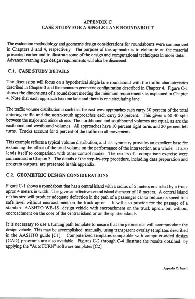
89
90
91
92
93
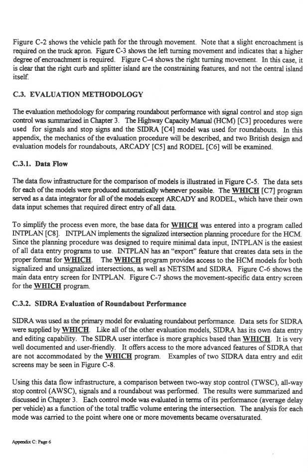
94
95
96
97
98
99
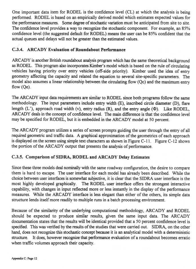
100
101
102
103
104
105

106
Justification and Feasibility of Roundabout
 Justification and Feasibility of Roundabout Shruti B. Khara M. E. Sem IV Transportation Engineering L. D. College of Engineering Ahmedabad e-mail shruti21063@gmail.com Prof. Ashutosh K. Patel Lecturer
Roundabout Planning and Operation
 Roundabout Planning and Operation Course No: C05-011 Credit: 5 PDH Gilbert Gedeon, P.E. Continuing Education and Development, Inc. 9 Greyridge Farm Court Stony Point, NY 10980 P: (877) 322-5800 F: (877)
Modern Roundabouts: a guide for application
 Modern Roundabouts: a guide for application Kentucky Community Transportation Innovation Academy 2005 The contents of this booklet reflect the views of the authors who are responsible for the facts and
ALLEY 24 TRAFFIC STUDY
 ALLEY 24 TRAFFIC STUDY in City of Frostburg, Maryland January 2013 3566 Teays Valley Road Hurricane, WV Office: (304) 397-5508 www.denniscorporation.com Alley 24 Traffic Study January 2013 Frostburg, Maryland
Highway 111 Corridor Study
 Highway 111 Corridor Study June, 2009 LINCOLN CO. HWY 111 CORRIDOR STUDY Draft Study Tea, South Dakota Prepared for City of Tea Sioux Falls Metropolitan Planning Organization Prepared by HDR Engineering,
133 rd Street and 132 nd /Hemlock Street 132 nd Street and Foster Street MINI ROUNDABOUTS. Overland Park, Kansas
 133 rd Street and 132 nd /Hemlock Street 132 nd Street and Foster Street MINI ROUNDABOUTS Overland Park, Kansas September 1, 2017 TABLE OF CONTENTS 1. INTRODUCTION... 1 2. LITERATURE REVIEW... 1 3. CONCEPT
TRANSPORTATION ANALYSIS REPORT US Route 6 Huron, Erie County, Ohio
 TRANSPORTATION ANALYSIS REPORT US Route 6 Huron, Erie County, Ohio December 12, 2012 Prepared for: The City of Huron 417 Main Huron, OH 44839 Providing Practical Experience Technical Excellence and Client
Recommended Roadway Plan Section 2 - Land Development and Roadway Access
 Recommended Roadway Plan Section 2 - Land Development and Roadway Access SECTION 2 Land Development and Roadway Access 2.1 Land Use and Access Management The Federal Highway Administration (FHWA) defines
Traffic Signal Design
 Traffic Signal Design Instructor: S. M. Mahdi Amiripour m.amiripour@gmail.com 2 Introduction Intersection is an area shared by two or more roads Designated for the vehicles to turn to different directions
City of Elizabeth City Neighborhood Traffic Calming Policy and Guidelines
 City of Elizabeth City Neighborhood Traffic Calming Policy and Guidelines I. Purpose: The City of Elizabeth City is committed to ensure the overall safety and livability of residential neighborhoods. One
8 PROPOSED ROUNDABOUT DUFFERIN STREET AND KING VAUGHAN ROAD INTERSECTION CITY OF VAUGHAN
 8 PROPOSED ROUNDABOUT DUFFERIN STREET AND KING VAUGHAN ROAD INTERSECTION CITY OF VAUGHAN The Transportation Services Committee recommends the adoption of the recommendation contained in the following report
Chapter 2: Standards for Access, Non-Motorized, and Transit
 Standards for Access, Non-Motorized, and Transit Chapter 2: Standards for Access, Non-Motorized, and Transit The Washtenaw County Access Management Plan was developed based on the analysis of existing
TECHNICAL MEMORANDUM VDOT Central Region On Call Task Order
 Kittelson & Associates, Inc. T R A N S P O R T A T I O N E N G I N E E R I N G / P L A N N I N G 1850 Centennial Park Drive, Suite 130, 20191 P 703-885-8970 F 703-885-8971 TECHNICAL MEMORANDUM VDOT Central
Appendix T CCMP TRAIL TRAFFIC & TRANSPORTATION DESIGN STANDARD
 Appendix T CCMP 3.3.4 TRAIL TRAFFIC & TRANSPORTATION DESIGN STANDARD 3.3.4 Trail Traffic and Transportation Design Multi-use trails have certain design standards, which vary depending on the agency that
TRAFFIC STUDY GUIDELINES Clarksville Street Department
 TRAFFIC STUDY GUIDELINES Clarksville Street Department 9/1/2009 Introduction Traffic studies are used to help the city determine potential impacts to the operation of the surrounding roadway network. Two
A Traffic Operations Method for Assessing Automobile and Bicycle Shared Roadways
 A Traffic Operations Method for Assessing Automobile and Bicycle Shared Roadways A Thesis Proposal By James A. Robertson Submitted to the Office of Graduate Studies Texas A&M University in partial fulfillment
THE FUTURE OF THE TxDOT ROADWAY DESIGN MANUAL
 THE FUTURE OF THE TXDOT ROADWAY DESIGN MANUAL Kenneth Mora, P.E. (Design Division) 10/10/2017 Table of contents 1 2 Reduction in FHWA design controlling criteria Innovative Intersection Guidance 3-7 8-42
City of Prince Albert Statement of POLICY and PROCEDURE. Department: Public Works Policy No. 66. Section: Transportation Issued: July 14, 2014
 Page: 1 of 8 1 POLICY 1.01 The City shall follow all of the specifications in the Manual of Uniform Traffic Control Devices for Canada, prepared by the National Committee of Uniform Traffic Control, and
Project Report. South Kirkwood Road Traffic Study. Meadows Place, TX October 9, 2015
 Meadows Place, TX October 9, 2015 Contents 1 Introduction... 1 2 Data Collection... 1 3 Existing Roadway Network... 2 4 Traffic Volume Development... 2 5 Warrant Analysis... 3 6 Traffic Control Alternative
ENHANCED PARKWAY STUDY: PHASE 2 CONTINUOUS FLOW INTERSECTIONS. Final Report
 Preparedby: ENHANCED PARKWAY STUDY: PHASE 2 CONTINUOUS FLOW INTERSECTIONS Final Report Prepared for Maricopa County Department of Transportation Prepared by TABLE OF CONTENTS Page EXECUTIVE SUMMARY ES-1
Evaluating Roundabout Capacity, Level of Service and Performance
 Roundabouts with Metering Signals ITE 2009 Annual Meeting, San Antonio, Texas, USA, August 9-12, 2009 Evaluating Roundabout Capacity, Level of Service and Performance Presenter: Rahmi Akçelik rahmi.akcelik@sidrasolutions.com
Introduction to Roundabout Analysis Using ARCADY
 Introduction to Roundabout Analysis Using ARCADY Toronto SimCap User Group Technical Event and ITE Toronto Section Social Event July 22, 2014 Phil Weber, P.Eng. GHD Inc. (The Home of Ourston Roundabout
MUTCD Part 6: Temporary Traffic Control
 MUTCD Part 6: Temporary Traffic Control OMUTCD English units are preferred. OHIO MANUAL OF UNIFORM TRAFFIC CONTROL DEVICES TABLE OF CONTENTS PREFACE INTRODUCTION TABLE OF CONTENTS PART 1. GENERAL Chapter
Module 3 Developing Timing Plans for Efficient Intersection Operations During Moderate Traffic Volume Conditions
 Module 3 Developing Timing Plans for Efficient Intersection Operations During Moderate Traffic Volume Conditions CONTENTS (MODULE 3) Introduction...1 Purpose...1 Goals and Learning Outcomes...1 Organization
TRAFFIC SIGNAL WARRANT STUDY
 TRAFFIC SIGNAL WARRANT STUDY 5 th STREET & ENCHANTED PINES DRIVE JANUARY 2013 TRAFFIC OPERATIONS ENGINEERING SERVICES/PUBLIC WORKS DEPARTMENT TABLE OF CONTENTS INTERSECTION LOCATION MAP ii INTRODUCTION
2.0 LANE WIDTHS GUIDELINE
 2.0 LANE WIDTHS GUIDELINE Road Engineering Design Guidelines Version 2.0.1 May 2018 City of Toronto, Transportation Services City of Toronto Page 0 Background In early 2014, Transportation Services initiated
METHODOLOGY. Signalized Intersection Average Control Delay (sec/veh)
") Chapter 5 Traffic Analysis 5.1 SUMMARY US /West 6 th Street assumes a unique role in the Lawrence Douglas County transportation system. This principal arterial street currently conveys commuter traffic
Chapter 5 Traffic Analysis 5.1 SUMMARY US /West 6 th Street assumes a unique role in the Lawrence Douglas County transportation system. This principal arterial street currently conveys commuter traffic
Introduction Roundabouts are an increasingly popular alternative to traffic signals for intersection control in the United States. Roundabouts have a
 HIGH-CAPACITY ROUNDABOUT INTERSECTION ANALYSIS: GOING AROUND IN CIRCLES David Stanek, PE and Ronald T. Milam, AICP Abstract. Roundabouts have become increasingly popular in recent years as an innovative
Roundabout Prequalification Training. March 11, 2015
 Roundabout Prequalification Training March 11, 2015 Presenters American Structurepoint, Inc. Jeromy Grenard, PE, PTOE Craig Parks, PE Why Roundabouts? Everybody else is building them? They look cool? Circles
1.3.4 CHARACTERISTICS OF CLASSIFICATIONS
 Geometric Design Guide for Canadian Roads 1.3.4 CHARACTERISTICS OF CLASSIFICATIONS The principal characteristics of each of the six groups of road classifications are described by the following figure
Access Location, Spacing, Turn Lanes, and Medians
 Design Manual Chapter 5 - Roadway Design 5L - Access Management 5L-3 Access Location, Spacing, Turn Lanes, and Medians This section addresses access location, spacing, turn lane and median needs, including
City of Albert Lea Policy and Procedure Manual 4.10 ALBERT LEA CROSSWALK POLICY
 4.10 ALBERT LEA CROSSWALK POLICY PURPOSE: Pedestrian crosswalks are an integral part of our transportation infrastructure. To be effective and promote safety, marked crosswalks must be installed after
Abstract. Background. protected/permissive operation. Source: Google Streetview, Fairview/Orchard intersection
 ITE 2015 Western District Annual Meeting Ada County Highway District s Flashing Yellow Arrow Initiative Primary Author: Tim Curns, PE Ada County Highway District Traffic Engineer Author: Andrew Cibor,
ROUNDABOUTS/TRAFFIC CIRCLES
 GENERAL 1. Description This standard identifies minimum requirements that shall be met for Roundabouts and Neighborhood Traffic Circles in the design and construction of elements for Arlington County Horizontal
Small Area Study U.S. Route 220 and VA Route 615 Intersection. Bath County, Virginia
 Small Area Study U.S. Route 220 and VA Route 615 Intersection Bath County, Virginia Prepared by the Central Shenandoah Planning District Commission Final Report February 2018 Table of Contents 1. INTRODUCTION...
10.0 CURB EXTENSIONS GUIDELINE
 10.0 CURB EXTENSIONS GUIDELINE Road Engineering Design Guidelines Version 1.0 March 2017 City of Toronto, Transportation Services City of Toronto Page 0 Background In early 2014, Transportation Services
Off-road Trails. Guidance
 Off-road Trails Off-road trails are shared use paths located on an independent alignment that provide two-way travel for people walking, bicycling, and other non-motorized users. Trails specifically along
Roundabouts The Virginia Experience
 Roundabouts The Virginia Experience Purpose of Briefing Misconceptions Background on Roundabouts How they pertain to Virginia Definition & Operational Characteristics Roundabouts Vs. Traffic signals Considerations
Roundabout Feasibility Memorandum
 Roundabout Feasibility Memorandum To From Gwen Pipkin Bill Howell Date June 18, 2013 Subject Roundabout Feasibility Study SR 29 PD&E Study From Oil Well Road to SR 82 Collier County, FL FPID 417540-1-22-01
Roundabout Design 101: Principles, Process, and Documentation
 Design 101: Principles, Process, and Documentation Part 1 March 7, 2012 Well designed roundabouts should minimize accidents, delay and costs for everyone using the intersection. This session covers the
Roundabouts in Australia: the state of the art on models and applications
 Roundabouts in Australia: the state of the art on models and applications Seminar Presentation One-day International Meeting on Roundabouts Università di Pisa - Corso di TECNICA del TRAFFICO, Livorno,
Simulation Analysis of Intersection Treatments for Cycle Tracks
 Abstract Simulation Analysis of Intersection Treatments for Cycle Tracks The increased use of cycle tracks also known as protected bike lanes has led to investigations of how to accommodate them at intersections.
Chapter 5 DATA COLLECTION FOR TRANSPORTATION SAFETY STUDIES
 Chapter 5 DATA COLLECTION FOR TRANSPORTATION SAFETY STUDIES 5.1 PURPOSE (1) The purpose of the Traffic Safety Studies chapter is to provide guidance on the data collection requirements for conducting a
Neighborhood Traffic Calming Policy & Guidelines
 Policy & Guidelines Town of Lantana 500 Greynolds Circle Lantana, FL 33462-4594 Index Topic Page Introduction 3 Definitions 4 Objectives 5 Policies 5 Process 6 Phases of Traffic Calming Study 7 Rating
Updated Roundabout Analysis Methodology
 Updated Roundabout Analysis Methodology In 1998, the Transportation Planning Analysis Unit (TPAU) working as part of the Roundabout Task Group selected the interim roundabout methodologies of the SIDRA
Traffic Impact Study WestBranch Residential Development Davidson, NC March 2016
 Traffic Impact Study WestBranch Residential Development Davidson, NC March 216 TRAFFIC IMPACT STUDY FOR THE WestBranch Residential Development LOCATED IN DAVIDSON, NC Prepared For: Lennar Carolinas, LLC
Course Instructions. 3 Easy Steps to Complete the Course: 1.) Read the Course PDF Below.
 Read the Course PDF Below.") Course Instructions NOTE: The following pages contain a preview of the final exam. This final exam is identical to the final exam that you will take online after you purchase the course. After you purchase
Course Instructions NOTE: The following pages contain a preview of the final exam. This final exam is identical to the final exam that you will take online after you purchase the course. After you purchase
4.0 TRAFFIC IMPACT STUDIES
 SECTION 4 4.0 TRAFFIC IMPACT STUDIES 4.1 TRAFFIC IMPACT STUDY REQUIREMENTS The City has established Traffic Impact Study (TIS) requirements for the purpose of ensuring that both the quantitative and qualitative
Chapter 7 Intersection Design
 hapter 7 Dr. Yahya Sarraj Faculty of Engineering The Islamic University of Gaza An intersection is an area, shared by two or more roads, whose main function is to provide for the change of route directions.
INTERSECTIONS AT GRADE INTERSECTIONS
 INTERSECTIONS 1 AT GRADE INTERSECTIONS INTERSECTIONS INTERSECTIONS = INTERRUPTED FACILITIES Definitions and key elements An intersection is defined as an area where two or more roadways join or cross.
City of Homewood Transportation Plan
 City of Homewood Transportation Plan Prepared for: City of Homewood, Alabama Prepared by: Skipper Consulting, Inc. May 2007 TABLE OF CONTENTS INTRODUCTION... 1 BACKGROUND INFORMATION... 1 EXISTING TRANSPORTATION
Appendix A: Crosswalk Policy
 Appendix A: Crosswalk Policy Appendix A: Crosswalk Policy Introduction This citywide Crosswalk Policy is aimed at improving pedestrian safety and enhancing pedestrian mobility by providing a framework
MUTCD Part 6G: Type of Temporary Traffic Control Zone Activities
 MUTCD Part 6G: Type of Temporary Traffic Control Zone Activities 6G.01 Typical Applications Each temporary traffic control (TTC) zone is different. Many variables, such as location of work, highway type,
Existing Conditions. Date: April 16 th, Dan Holderness; Coralville City Engineer Scott Larson; Coralville Assistant City Engineer
 Date: April 16 th, 2015 To: From: Re: Dan Holderness; Coralville City Engineer Scott Larson; Coralville Assistant City Engineer Darian Nagle-Gamm, Traffic Engineering Planner Highway 6 (2 nd Street) /
Update to DOTD Roundabout Design Policy
 Update to DOTD Roundabout Design Policy Roundabout In Louisiana Louisiana has 18 roundabouts in operation and 53 proposed History EDSM s or Engineering Directives and Standards set DOTD policies, procedures,
Broad Street Bicycle Boulevard Design Guidelines
 Broad Street Bicycle Boulevard Design Guidelines Building from the strategies introduced in the 2013 Bicycle Transportation Plan and community input received thus far, City Transportation Staff have identified
APPENDIX A: Complete Streets Checklist DRAFT NOVEMBER 2016
 APPENDIX A: Complete Streets Checklist DRAFT NOVEMBER 2016 Complete Streets Checklist MetroPlan Orlando s Complete Streets Checklist is an internal planning tool for staff to further implementation of
INDEX. Geometric Design Guide for Canadian Roads INDEX
 Acceleration lane, see Lanes, Acceleration Access, 8.1 Access Management and Functional Classification 8.2 Access Management by Design Classification 8.3 Access Configuration 8.4 Building Set-Back Guidelines
1 VicRoads Access Management Policies May 2006 Ver VicRoads Access Management Policies May 2006 Version 1.02
 1 VicRoads Access Management Policies May 2006 Ver 1.02 VicRoads Access Management Policies May 2006 Version 1.02 2 VicRoads Access Management Policies May 2006 Ver 1.02 FOREWORD FOR ACCESS MANAGEMENT
Traffic Impact Study. Westlake Elementary School Westlake, Ohio. TMS Engineers, Inc. June 5, 2017
 TMS Engineers, Inc. Traffic Impact Study Westlake Elementary School Westlake, Ohio June 5, 2017 Prepared for: Westlake City Schools - Board of Education 27200 Hilliard Boulevard Westlake, OH 44145 TRAFFIC
ORANGE COUNTY PUBLIC WORKS TRAFFIC INVESTIGATIONS
 ORANGE COUNTY PUBLIC WORKS TRAFFIC INVESTIGATIONS STAFF REPORT OF: January 6, 2019 SUPERVISORIAL DISTRICT: 5 SUBJECT: LOCATION: INVESTIGATOR: O Neill Drive at Roanoke Drive; Ladera Ranch; TB 922-E6 Clever
Pennsylvania Department of Transportation. Guide to Roundabouts. Guidelines for the Implementation of Roundabouts in Transportation Facilities
 Pennsylvania Department Guide to Roundabouts PENNDOT Publication Number 414 Guidelines for the Implementation of Roundabouts in Transportation Facilities Prepared by: Michael Baker Jr., Inc. May, 2001
CITY OF SASKATOON COUNCIL POLICY
 ORIGIN/AUTHORITY Clause 1, Report No. 1-1980 and Clause 4, Report No. 22-1990 of the Works and Utilities Committee; Clause 6, Report No. 17-2004 of the Planning and Operations Committee; and Clause D5,
DEFINITIONS Activity Area - Advance Warning Area Advance Warning Sign Spacing Advisory Speed Approach Sight Distance Attended Work Space
 DEFINITIONS Activity Area - that part of a TTC zone activity area where the work actually takes place. It consists of the work space, traffic space and one or more buffer spaces. Advance Warning Area -
CHAPTER 7 ACCESS MANAGEMENT. Background. Principles of Access Management. Hennepin County Transportation Systems Plan (HC-TSP)
") CHAPTER 7 ACCESS MANAGEMENT Background Principles of Access Management Hennepin County Transportation Systems Plan (HC-TSP) Chapter 7 Access Management 7.1 Background Access management has become an important
CHAPTER 7 ACCESS MANAGEMENT Background Principles of Access Management Hennepin County Transportation Systems Plan (HC-TSP) Chapter 7 Access Management 7.1 Background Access management has become an important
Roundabout Design Principles
 des Carrefours Giratoires Roundabout Design Principles NCLUG Roundabout Luncheon Tuesday, March 4, 2014 Prepared by: des Carrefours Agenda Giratoires Roundabout design process: Planning and Policy Lane
TOWN OF CHAPEL HILL POLICY AND PROCEDURES FOR TRAFFIC CALMING MEASURES
 TOWN OF CHAPEL HILL POLICY AND PROCEDURES FOR TRAFFIC CALMING MEASURES (Adopted by the Town Council on June 30, 2004) (Revised December 6, 2010) (Revised February 8, 2016) POLICY AND PROCEDURES FOR TRAFFIC
BLOSSOM AT PICKENS SIGNALIZED INTERSECTION IMPROVEMENT STUDY
 BLOSSOM AT PICKENS SIGNALIZED INTERSECTION IMPROVEMENT STUDY Class Project Report for ECIV 542 Traffic Engineering Submitted by Omor Sharif Muchun Song Narges Kaveshgar Quyen Pham Chih-Yao Lin Submission
PennDOT ICE Policy An Introduction
 PennDOT ICE Policy An Introduction January 2018 What is Intersection Control Evaluation (ICE)? Purpose: To consistently consider and screen among many proven combinations of geometry and traffic control
TRAFFIC CALMING TOOLBOX
 TRAFFIC CALMING TOOLBOX Traffic control devices are those official signs and striping placed in the public right-of-way and recognized by the public such as STOP signs, curve warning signs, centerline
Roundabouts in Edmonton - A Comparison to the State-of-the-Art
 Roundabouts in Edmonton - A Comparison to the State-of-the-Art Authors: Carl Clayton, P.Eng. P.E. PTOE Stantec Consulting Ltd. Chuan Kua, P.Eng. City of Edmonton, Transportation and Streets Brice Stephenson,
City of Port St. Lucie Neighborhood Traffic Calming Policy City of Port St. Lucie Neighborhood Traffic Calming Policy Adopted June 26, 2017
 City of Port St. Lucie Neighborhood Traffic Calming Policy Adopted June 26, 2017 INTRODUCTION The City of Port St. Lucie is committed to ensuring the overall safety and livability of residential neighborhoods.
TRAFFIC IMPACT STUDY CRITERIA
 Chapter 6 - TRAFFIC IMPACT STUDY CRITERIA 6.1 GENERAL PROVISIONS 6.1.1. Purpose: The purpose of this document is to outline a standard format for preparing a traffic impact study in the City of Steamboat
400 Intersection Design. Table of Contents. 401 Intersections At-Grade Two Way Left Turn Lanes (TWLTL)... 9
... 9") 4 Intersection Design Table of Contents 41 Intersections At-Grade... 1 41.1 Intersection Locations... 1 41.2 Intersection Traffic Control and Operational Analysis... 1 41.2.1 Signals... 1 41.2.2 Stop Control...
4 Intersection Design Table of Contents 41 Intersections At-Grade... 1 41.1 Intersection Locations... 1 41.2 Intersection Traffic Control and Operational Analysis... 1 41.2.1 Signals... 1 41.2.2 Stop Control...
Evaluation of M-99 (Broad Street) Road Diet and Intersection Operational Investigation
 Road Diet and Intersection Operational Investigation") Evaluation of M-99 (Broad Street) Road Diet and Intersection Operational Investigation City of Hillsdale, Hillsdale County, Michigan June 16, 2016 Final Report Prepared for City of Hillsdale 97 North Broad
Evaluation of M-99 (Broad Street) Road Diet and Intersection Operational Investigation City of Hillsdale, Hillsdale County, Michigan June 16, 2016 Final Report Prepared for City of Hillsdale 97 North Broad
Roundabout Design 101: Roundabout Capacity Issues
 Design 101: Capacity Issues Part 2 March 7, 2012 Presentation Outline Part 2 Geometry and Capacity Choosing a Capacity Analysis Method Modeling differences Capacity Delay Limitations Variation / Uncertainty
TRAFFIC IMPACT STUDY And A TRAFFIC SIGNAL WARRANT ANALYSIS FOR A SENIOR LIVING AND APARTMENT DEVELOPMENT
 TRAFFIC IMPACT STUDY And A TRAFFIC SIGNAL WARRANT ANALYSIS FOR A SENIOR LIVING AND APARTMENT DEVELOPMENT DEERFIELD TOWNSHIP, WARREN COUNTY, OHIO Nantucket Circle and Montgomery Road () Prepared for: ODLE
CHAPTER 1 STANDARD PRACTICES
 CHAPTER 1 STANDARD PRACTICES OBJECTIVES 1) Functions and Limitations 2) Standardization of Application 3) Materials 4) Colors 5) Widths and Patterns of Longitudinal Pavement Marking Lines 6) General Principles
PEDESTRIAN ACCOMMODATIONS DPS 201 AT ROUNDABOUTS
 PEDESTRIAN ACCOMMODATIONS DPS 201 AT ROUNDABOUTS WHY THEY WORK FOR PEDESTRIANS IF DESIGNED CORRECTLY Separated sidewalks direct peds to crosswalks Splitter island Slow speed exit Truck apron Crosswalk
Subject: Use of Pull-off Areas in Work Zones Page: 1 of 13. Brief Description: Guidance for the use and placement of pull-off area in work zones.
 6 - G2 Subject: Use of Pull-off Areas in Work Zones Page: 1 of 13 MdMUTCD REF. NO. None Date Issued: 09/09 Effective Date: 09/09 Brief Description: Guidance for the use and placement of pull-off area in
Implementing Complete Streets in Ottawa. Project Delivery Process and Tools Complete Streets Forum 2015 October 1, 2015
 Implementing Complete Streets in Ottawa October 1, 2015 The Essentials Complete Streets Implementation Framework will become part of the routine delivery of City transportation projects Approach uses every
Roadways. Roadways III.
 Introduction 97 Roadway Design Principles 98 Safe Speeds 99 Optimizing of Street Space 00 Minimum Lane Widths in the City of Boston 02 Design Features that Reduce Operating Speeds 05 Travel Lanes Transit
Traffic Impact Analysis Walton Acres at Riverwood Athletic Club Clayton, NC
 Traffic Impact Analysis Walton Acres at Riverwood Athletic Club Clayton, NC 1. TABLE OF CONTENTS INTRODUCTION...1 1.1. Site Location and Study Area...1 1.2. Proposed Land Use and Site Access...2 1.3.
Coquitlam Cross-town Bike Route Improving Bicycle Facilities in a Mature Suburban Environment
 Coquitlam Cross-town Bike Route Improving Bicycle Facilities in a Mature Suburban Environment Sarah Rocchi, Vice-President, Projects, Opus International Consultants (Main Presenter) Catherine Mohoruk,
SELECTED ROADWAY CAPACITY ANALYSIS
 CHAPTERFOUR SELECTED ROADWAY CAPACITY ANALYSIS 4.1 SELECTED ROADWAY CAPACITY ANALYSIS Introduction Capacity analysis was performed on six selected roadways within the Dearborn County study area using the
INTRODUCTION THOROUGHFARE SYSTEM CLASSIFICATIONS
 INTRODUCTION The thoroughfare plan will assist public officials in the development of a specialized system for efficient and safe movement of vehicular traffic while minimizing potential conflicts with
THIS PAGE LEFT BLANK INTENTIONALLY
 GA SR 25 Spur at Canal Road Transportation Impact Analysis PREPARED FOR GLYNN COUNTY, GEORGIA 1725 Reynolds Street, Suite 300 Brunswick, Georgia 31520 PREPARED BY 217 Arrowhead Boulevard Suite 26 Jonesboro,
Innovative Intersections
 Innovative Intersections Things You Need to Know About FDOT D-7 Safety Academy October 19, 2016 Mark Doctor FHWA Resource Center Atlanta, GA HOW DO YOU FEEL??? about innovative intersections??? Why is
City of Wayzata Comprehensive Plan 2030 Transportation Chapter: Appendix A
 A1. Functional Classification Table A-1 illustrates the Metropolitan Council s detailed criteria established for the functional classification of roadways within the Twin Cities Metropolitan Area. Table
Chapter 5 5. INTERSECTIONS 5.1. INTRODUCTION
 Chapter 5 5. INTERSECTIONS 5.1. INTRODUCTION Intersections are the physical component of the roadways where two highways intersect. They are the most complex element of roadways, since it requires more
M-58 HIGHWAY ACCESS MANAGEMENT STUDY Mullen Road to Bel-Ray Boulevard. Prepared for CITY OF BELTON. May 2016
 M-58 HIGHWAY ACCESS MANAGEMENT STUDY Prepared for CITY OF BELTON By May 2016 Introduction Missouri State Highway 58 (M-58 Highway) is a major commercial corridor in the City of Belton. As development has
Complete Street Analysis of a Road Diet: Orange Grove Boulevard, Pasadena, CA
 Complete Street Analysis of a Road Diet: Orange Grove Boulevard, Pasadena, CA Aaron Elias, Bill Cisco Abstract As part of evaluating the feasibility of a road diet on Orange Grove Boulevard in Pasadena,
ROUNDABOUT MODEL COMPARISON TABLE
 Akcelik & Associates Pty Ltd PO Box 1075G, Greythorn, Vic 3104 AUSTRALIA info@sidrasolutions.com Management Systems Registered to ISO 9001 ABN 79 088 889 687 ROUNDABOUT MODEL COMPARISON TABLE Prepared
SECTION 1 - TRAFFIC PLANNING
 SECTION 1 - TRAFFIC PLANNING 1.1 TRAFFIC OPERATIONS 1.1.1 Roadway Functional Classification The Multnomah County Comprehensive Framework Plan s Policy 34: Trafficways and the Functional Classification
Cycle Track Design Best Practices Cycle Track Sections
 Design Best Practices Sections It is along street segments where the separation and protection methods of cycle tracks offer more comfort than conventional bicycle lanes, and are more attractive to a wide
A Review of Roundabout Safety Performance in the United States
 A Review of Roundabout Safety Performance in the United States 1.0 Introduction Aimee Flannery, Ph.D. Lily Elefteriadou, Ph.D. Roundabouts are a new form of at-grade intersection design that have been
TRAFFIC CALMING GUIDE FOR TORONTO CITY OF TORONTO TRANSPORTATION SERVICES DIVISION
 TRAFFIC CALMING GUIDE FOR TORONTO CITY OF TORONTO TRANSPORTATION SERVICES DIVISION CITY OF TORONTO TRANSPORTATION SERVICES DIVISION 2016 TRAFFIC CALMING GUIDE FOR TORONTO TABLE OF CONTENTS Introduction
TRAFFIC SIGNALS OR ROUNDABOUT AT THIS UNUSUAL INTERSECTION?
 TRAFFIC SIGNALS OR ROUNDABOUT AT THIS UNUSUAL INTERSECTION? Presenting Author Phil Weber, P.Eng. GHD Inc. (The Home of Ourston Engineering) 11 Allstate Parkway, Suite 310 Markham, ON L3R 9T8 Phone (905)
JCE 4600 Transportation Engineering. Traffic Control
 JCE 4600 Transportation Engineering Traffic Control Human Factors Primary Driving Tasks NAVIGATION GUIDANCE CONTROL What makes a Traffic Control Device Effective? Fulfill a need Command Attention Convey
Access Management in the Vicinity of Intersections
 Access Management in the Vicinity of Intersections FHWA-SA-10-002 Technical Summary Photo: Ralph Bentley (used with permission) 0 Access Management is: The design, implementation and management of entry