WELCOME TO THE HOBIE WAY OF LIFE
|
|
|
- April Cummings
- 5 years ago
- Views:
Transcription
1

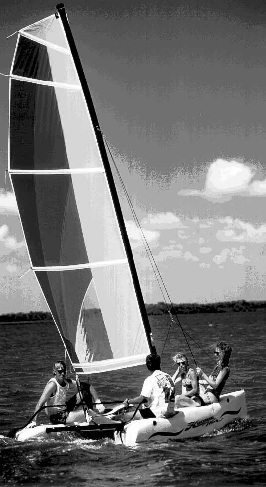
2 WELCOME TO THE HOBIE WAY OF LIFE Congratulations on the purchase of your new Wave and welcome to the HOBIE sailing family. The HOBIE Wave cannot be outgrown. It can be sailed by children up through senior citizens. A 90-pound youth can handle it easily a single adult can sail it at top performance and a crew of four can cruise in comfort. We offer this manual as a guide to increased safety and enjoyment of your new boat. The purpose of this publication is to provide easy, simple and accurate instructions on how to get your Wave ready for the water. Please read them carefully and familiarize yourself with the boat and all of the parts spread before you. Whether you are a new sailor or a veteran of many years, we recommend that you read this thoroughly before your first sail and TRY IT OUR WAY FIRST! If you are new to sailing, this manual alone is not intended to teach you how to sail. There are many excellent books, videos and courses on the safe handling of small sailboats. We suggest that you contact your local sailboat dealer, college or Coast Guard Auxiliary for recommendations. Watch for overhead wires whenever you are rigging, launching, sailing or trailering with the mast up. CON- TACT OF THE MAST WITH POWER LINES COULD BE FATAL! Be certain that the rigging area and the area that you will be sailing in are free of overhead power lines. Report any such power lines to your local power authority and SAIL ELSEWHERE. We take pride in presenting the Wave to you and hope that you'll take as much pride in owning her. Fair winds and good sailing! Hobie Cat

3 This assembly manual takes you stepby-step through the setting-up and sailing of your new HOBIE Wave. This manual will help you understand each part in detail. For more information refer to the Wave assembly video tape and your Hobie Cat dealer. Setting up your Wave PAGE Wave terminology...2 List of parts...3 Knots to use...4 The hulls...4 Trampoline assembly Tensioning the trampoline...6 Mast assembly...7 Stepping the mast Sail Downhaul and adjustment...10 Mainsheet...10 Rudder assembly...10 Tiller cross bar...11 Setting up the CLUB Wave Please refer to the CLUB WAVE assembly page for each item identified by the following "SEE CLUB". This will identify items that differ from the standard Hobie Wave assembly. Sailing your Wave...PAGE Balancing the boat...13 Steering...13 Sail power Righting the boat Turning...14 Launching/landing Rudder tuning Car topping/trailering Safety tips...back page 1
4 Wave Terminology MAST FLOAT BATTENS MAST SAIL FORESTAY SHROUD FORESTAY / BRIDLE ADJUSTER BRIDLE DOWNHAUL SAIL CLEW MAIN SHEET SYSTEM TILLER ARM RUDDER CASTINGS HULL RUDDER 2
 Hulls with hardware (1) Front cross bar (1) Rear cross bar (1) Trampoline (1) Box of small parts")
 SMALL PARTS DETAIL ➀ ➁ ➂ ➃ ➄ ➀ ➁ ➂ ➃ ➄ Mainsheet system Downhaul line Righting line Forestay wire with adjuster and bridle")
5 PARTS Check the boat and parts carefully to be sure that all of the parts are present and that the boat is in good order. ➆ ➄ LIST OF PARTS You should have: ➀ ➁ ➃ ➀ ➀ ➁ ➂ ➃ ➄ ➅ ➆ ➇ (2) Hulls with hardware (1) Front cross bar (1) Rear cross bar (1) Trampoline (1) Box of small parts (1) Sail, battens and sail bag (2) Rudder assemblies (1) Tiller cross bar ➂ ➇ ➅ NOT SHOWN: (1) Upper mast section (1) Lower mast section (1) Mast float (1) Trampoline lace rod (taped to battens) SMALL PARTS DETAIL ➀ ➁ ➂ ➃ ➄ ➀ ➁ ➂ ➃ ➄ Mainsheet system Downhaul line Righting line Forestay wire with adjuster and bridle wires Shroud wires NOT SHOWN: Main halyard line 3
 as in figure 1. A tarp or pads may be desirable under the hull if the ground surface is rough.")

6 ASSEMBLY INSTRUCTIONS KNOTS TO USE FIGURE 8 KNOT AT END OF LINE FIGURE 8 KNOT BOWLINE KNOT HALYARD KNOT CLEATING OFF A LINE 1. THE HULLS Lay the hulls on the ground on their sides with the bottoms to the center (graphics down) as in figure 1. A tarp or pads may be desirable under the hull if the ground surface is rough. Place the hulls about six feet apart. PLUG There is one plug in the rear of each hull (shown inset). These plugs are used to drain the hulls. The plugs should be in place before sailing. Remove the plugs after sailing to drain any water that may have leaked into the hulls. It is best to travel with and store the boat with the plugs removed to allow for pressure changes due to heating, cooling and altitude changes. This will prevent warping of the hull surface. FIGURE 1a 2. CROSSBARS AND TRAMPOLINE ASSEMBLY Figure 2a shows an example of the assembled trampoline assembly. To assemble the cross bars and trampoline onto the hulls, first locate the crossbars and trampoline. These parts are partly pre-assembled by the factory. "SEE CLUB" FIGURE 2a Un-roll the trampoline assembly and position it between the hulls. The front of the trampoline has a rope molded into the edge seam and two "D" rings molded onto the top surface. The sides and rear of the trampoline have loops and cut outs along the edges. The front crossbar has a casting with mast step ball located on the top center. The rear crossbar has (4) webbing straps with velcro and a small stainless steel loop fitting on the top and center. 4
 by loosening the screws just enough to slide the fitting out of the bar.")
.")
7 Upon first time assembly, you will need to feed the trampoline into the front cross bar. Remove one of the eye straps and block fittings with cable located near each end of the forward cross bar (figure 2b) by loosening the screws just enough to slide the fitting out of the bar. Slide the trampoline into the front cross bar with the hiking straps up. Replace the eye strap and block fitting to its original position and tighten. FIGURE 2b Upon first time assembly it will then be necessary to feed the trampoline lace rod into the pocket at the rear of the trampoline (figure 2c). Position it with equal amounts extending from each side of the trampoline. FIGURE 2d(4) Bring the Webbing back around the rear bar in the opposite direction. FIGURE 2d(5) Repeat the previous steps for each strap. Then tuck each one under the velcro flaps. Fasten the velcro straps back to their anchors loosely. It will not be necessary to detach the cross bars from the trampoline during future disassembly and assembly. FIGURE 2c Position the rear cross bar along the rear of trampoline. Place it with the open track towards the trampoline and the small stainless steel loop fitting at the center on top. Position the four webbing straps (with velcro) in line with the openings that the lace rod passes through. FIGURE 2d(1) "SIDE VIEW" Pass the velcro straps over the top of the bar and away from the trampoline as in figure 2d(1). FIGURE 2d(2) Continue around the rear bar as in figure 2d(2). FIGURE 2d(3) Pass the webbing forward then around the lace rod through the trampoline opening from top to bottom as shown in figure 2d(3). Rear Bar Trampoline and lace rod Web strap Velcro Flap 5 Once the trampoline is assembled to the cross bars and they are in position, check to see that the velcro straps at the rear are loosely fastened. Lift the front crossbar and insert the left end into the left hull. Insert only partially. Lift the rear cross bar and insert the left end into the left hull. Keep the straps rolled around the rear cross bar as in figure 2d(5). Insert front and rear completely (see figure 2e). The cross bars have stops built into the underside that will limit the depth the cross bar can be inserted. Reach up and hold the right end of the front crossbar, and pull it down. This will rotate the left hull to the upright position. Straddle the right hull and rotate it to the upright position by grabbing the cross bar insert hole on the outboard side and pulling the hull to vertical. Insert the front cross bar partially. Align and insert the rear cross bar partially. Working front and rear, wiggle hull onto cross bars until fully inserted as in figure 2f. FIGURE 2e FIGURE 2f
 Cross bar stop As shown (from the underside of the trampoline) in figure 2g, on each side at the rear crossbar, locate the line")


 Start on either left or right side.")


8 Pass the two trampoline cables from the front crossbar through the trampoline side loops to the rear crossbar. Cable end Pulley block "D" ring FIGURE 2g (rear corner, underside) Cross bar stop As shown (from the underside of the trampoline) in figure 2g, on each side at the rear crossbar, locate the line that runs from the rear corner pulley block. Pass the line to the rear trampoline "D" ring and return through the small pulley block. Pass the end of the line through the trampoline cable end fitting and tie a "figure 8" knot as shown in the knot diagrams on page 4. Figure 2h is the top view of same. Making adjustments and re-tying the knot at the pulley block will loosen or tighten the side cables. The cables should be somewhat loose at this time. Be sure the "D" rings remain as pictured above and not pulled from one end when loaded as damage may result. FIGURE 2h (top view) To tension the trampoline, you will use the mainsheet system (block and tackle). Find the mainsheet system located with the small parts. The system line is prerun by the factory. Attach FIGURE 3b the shackle at the bottom of the blocks to the stainless steel loop fitting in the center of the rear cross bar. Pull the mainsheet hook, at the top of the system, up to the front of the trampoline. Hook the mainsheet to the ring fastened to the trampoline cable system at front of trampoline as in figure 3b. (Do Not fasten the mainsheet hook to the "D" ring that is attached to the trampoline) Start on either left or right side. Pull tension on the mainsheet until the cable system ring and hook near the "D" ring attached to the trampoline (FIGURE 3c). Position hook to engage ring thereby connecting the two rings FIGURE 3c together as in figure 3d. Release the mainsheet tension and unhook from ring. Repeat the process on the opposite side. Be sure all "D" rings are positioned as shown and not turned or pulled from ends as damage to the trampoline may result. FIGURE 3d 3. TENSIONING TRAMPOLINE As shown in figure 3a, hook the trampoline side cables onto the three hooks on each hull. (If you are re-assembling, be sure that the mainsheet system is loose or disconnected from ring at front of trampoline to keep cables loose). FIGURE 3a FIGURE 3f Adjust knot here Additional tension or reduced tension can be achieved by repositioning the knot as shown in figure 3f at rear end of cable (after disengaging the forward rings). The cables should be tight to make the trampoline area taut. Unhook rings at front, move knot and re-hook forward rings. Repeat until trampoline area is taut. In future assembly this adjustment will not be necessary unless trampoline becomes loose once again. 6 Tighten each velcro strap (4) to support the trampoline at the rear crossbar.


.")


9 4. MAST ASSEMBLY The mast is in two sections. The bottom section is aluminum and displays the warnings against sailing and assembling near overhead wires and power lines. Before raising the mast check again that you are in a safe area and always remember this warning. Insert the upper section into the lower section. Install the mast float to the upper mast section as in figure 4. First time assembly will require the removal of the two halyard pulley clevis pins, placement of the float assembly over the mast top casting and replacing the clevis pins with the screws and nuts provided with the float assembly. Be sure the blunt end of the float is facing forward towards blunt side of the mast. Attach the multi-hole adjuster to the forestay as shown in figure 5b with the clevis pin and ring at the end hole of the adjuster (top of the 7 holes). This is the loose adjustment for first assembly (photo shows third hole down). Shackle the bridle wires (thimble loop end) to the bottom of the adjuster. "SEE CLUB" This leaves the spring hooks at the very end of the forestay/ adjuster/ bridle assembly. FIGURE 5b 6. STEPPING THE MAST To set the mast into the upright position, position the mast base at the mast step ball located on the front crossbar as shown in figure 6a(1). The mast top and float should be positioned to the rear of the boat in the center of the rear crossbar. FIGURE 4 5. MAST WIRES The mast will be held in the upright position by two side wires (shrouds) and one front wire (forestay). The forestay will attach to two shorter wires (bridles) with a "7 hole" adjuster. Locate the three main (longer) wires and install onto the mast tang as shown in figure 5a using the 1/4" threaded shackle provided in the rig kit. The shorter forestay wire goes in the middle of the shackle with one shroud on either side. "SEE CLUB" FIGURE 6a(1) Connect the mast base to the step ball by positioning the step ball inside the mast base cup. Pass the pin through the mast base as shown in figure 6a(2). FIGURE 5a 7 FIGURE 6a(2)


 Check to be sure that the wires are not crossed.")
10 As shown in figure 6a(3) below, pass the long pin through the mast base. There is a small spring loaded ball lock that will keep the pin captive in the mast base. For safety, the pin should remain in the mast base while sailing. Check wires to be sure they are not crossed and that they are free to allow the mast to swing to the upright position. If you are stepping the mast by yourself or just to make things easier, pull the sail halyard hook forward, over the top of the shroud wires, to the bow. Hook into the bridle wire fitting. Loosely tie opposite end of halyard to the cleat at bottom end of the mast. This line will be used to hold mast in the upright position before forestay and bridle wires assembly are attached to the bow fittings. Before continuing, once again check for overhead power line wires that could contact the mast when raising. FIGURE 6a(3) Check to be sure that the wires are not crossed. Connect the left side shroud to the left hull with the opposing hooks as shown in figure 6b and 6c. FIGURE 6f Stand on the trampoline near the rear crossbar and lift the mast to your shoulder (figure 6f). FIGURE 6b FIGURE 6c Pass the split ring through the small hole in the two hooks to lock them together as in figure 6c. Slide the vinyl boot over the hook assembly to lock it in place as in figure 6d. The top of the boot must engage the wire swage (swage must protrude from top of boot) to prevent them from moving up the wire and possibly allowing the ring to be exposed. Repeat for right side shroud. WARNING!! FIGURE 6d Watch for overhead power lines. Never rig, trailer or sail the boat near overhead power lines. Mast contact with a power line could be fatal. Face forward on the boat with a wide stance for stability. Walk forward while lifting the mast until the side shrouds go tight preventing the mast from further forward movement. Lean your weight against the mast to hold it in this position. See figure 6g. Reach down to the halyard cleat and pull the halyard line tight. FIGURE 6g Fasten the line to the cleat in a secure manner as shown in "Knots" on page 4. 8
 while you get off the trampoline to fasten the bridle wires to the bow fittings. 7.")


11 The halyard line should be running from the top of the mast directly to the bow fitting. Carefully let go of mast to be sure that it will stay upright. If not, add tension to halyard line and re-cleat. This will hold mast in the upright position (see figure 6h) while you get off the trampoline to fasten the bridle wires to the bow fittings. 7. INSTALLING THE SAIL BATTENS Cleat at mouth of each tip If you have someone helping you rig, you can hold the mast upright while they follow the next step. FIGURE 6h Batten pocket Hollowed-out side of tip See that the forestay wire is not tangled and runs directly from mast tang fitting. Using the quick snap hooks on the ends of the bridle wires, attach to one bow and then to the other as in figure 6i and 6j. "SEE CLUB" Use the small plastic balls to grip and pull down on the bridle wires. FIGURE 7a Start here with a bowline knot Unfold the sail and lay it out on the trampoline. There will be a small bundle of thin lines tied to the top of the sail. These are the batten tension lines. Tie the batten tension lines to one of the the small grommets at the end of each batten pocket as diagramed in figure 7a (one to each batten pocket). Tie the lines using a bowline knot as found in the "knots" diagramed on page 4. It is best to tie the lines all to one side of the sail. Insert each batten (shortest batten at the top to longest batten at the bottom of the sail). FIGURE 6i FIGURE 6j Length adjustment of the forestay (figure 6k) is made to tension the mast wires. Tighten the forestay until all wires are somewhat rigid and without slop. Use the halyard line attached to the bow tang and cleated tightly to hold the mast well forward when making these adjustments. Release one bow bridle snap hook. Make adjustments to the clevis pin location in the adjuster and then reattach the bridle hook to the bow fitting. Release the FIGURE 6k halyard from the bow fitting and reposition it down the rear of the mast and secure to the cleat. Once this adjustment is made you can assemble and disassemble using only the quick snap hooks to the bow fittings unless the rig becomes loose after use. NOTE: It is normal for the shroud on the down wind (leeward side) to be loose while sailing. 9 Note that the batten ends have a "V" jam cleat molded into them. These "V" jam cleats will keep the tension line from slipping in only one direction. Note the hollowed-out side of the cleats. Pull the line from the flush side toward the hollowed side. The upper two battens are narrower and have a different cleat shape. To be sure these cleats work correctly, position these so that the hollowed out side of the cap faces the bowline that you have tied to the sail grommet. Position the larger caps so that the hollowed sides face away from each knot. Following the diagram in figure 7a, lace the tension lines through each batten end cap. Pass the line through the hole in the cap then through the grommet on the opposite side. For the smaller caps, pass the line over the "V" cleat, pull tension forcing the batten into the pocket, then pull the line into the cleat to hold it. For the larger caps, pass the line through the second hole in the cap, then pass the line through the first grommet and back to the "V" cleat. Pull tension on the line forcing the batten into the pocket and cleat it. Tie a small figure 8 knot in the end of each line to prevent the battens from falling from the sail if the line releases from the cleat. Tension each batten so that the batten is well seated and the wrinkles in the batten pockets are removed. Excessive batten tension will cause the sail to be more difficult to handle.


. Keep the line centered with the mast.")
12 8. RAISING THE SAIL Place the sail in the center of the trampoline with the exposed batten ends to the rear. The front of the sail has what is called a "luff rope" running the length of it. This rope is fed into the mast "luff" track when raising the sail. As shown in figure 8a, hook the halyard to the top of the sail. Pass the tail end of the halyard line through the thimble that holds the halyard hook and tie a knot. This will create a continuous loop with the halyard such as a flag halyard. This will allow you to pull the FIGURE 8a halyard hook back down the mast if the hook disengages from the sail while hoisting. Feed the top portion of sail into the mast track opening, then begin pulling on the halyard line. Use caution to be sure the sail feeds smoothly into the mast while raising. Hoist the sail all the way to the top of the mast. It will be necessary to help feed the sail into the track while hoisting. As shown in figure 8b, there is a two fingered hook at the top of the mast. The halyard has a small bead of metal which is held by this hook when fully raised. Hook When fully raised, pull the halyard line, while still holding tension, FIGURE 8b FIGURE 8c forward and away from the mast (figure 8b). Keep the line centered with the mast. Then, pull the line back against the mast. This will place the bead below the two fingered hook. Release the halyard to engage the hook (figure 8c). Repeat the process if the sail does not remain at the top of the mast. The line must be centered with the mast to engage the hook. Tie the halyard line to the mast cleat. 9. DOWNHAUL Locate the downhaul line. Tie it to the sail "tack" grommet near the mast (when finished sailing, leave it tied here). Pass the line down and through the center of the cleat mounted in the luff track of the mast. Run the line up to and through the "tack" grommet. Run the line back down to the cleat. Tension it and then tie to the cleat as shown in "knots" on page DOWNHAUL ADJUSTMENTS The downhaul should be tensioned just enough to remove the horizontal wrinkles in the sail luff (forward area). The boat will perform best with light tension in light air and a bit more when the wind is stronger. 10. MAINSHEET Hook the mainsheet to the "clew" grommet at the rear of the sail as shown in figure RUDDER ASSEMBLY Position the rudders as shown in Figure 11a. There is a left and a right rudder. Note the arms extending from the upper rudder castings. These "upper rudder" castings have an angle molded into them. The arms should be angled FIGURE 10 towards the center of the boat. You will also see a colored tab on the end of each arm, one green, one red. The red tab indicates the left rudder and the green the right. As shown in figure 11, line up the rudder pintles (metal pegs on the hulls) with the rudder castings (holes with plastic bushings). Push the rudder castings down onto the pintles. The rudder arm may need to be unlocked to allow easy positioning. Insert the retainer pins to lock the rudders in place. The pins will prevent the rudders from falling off the boat in the event of a capsize. FIGURE 11 Retainer pin The rudders are locked in the down position by pushing the rudder arm aft which will seat the rudder against the lower casting. Push the arm down to engage the locking cam. To release, lift the arm, then pull the arm forward until the rudder is in the "up" position. Place the arm down to engage the upper casting with the lower casting. Beaching will automatically release the rudders.

13 12. TILLER CROSSBAR The rudder arms are connected by a bar called the tiller crossbar. Position the crossbar between the two rudders with the elbow connector spring buttons facing down. Slide each connector partly into the tiller arms. Depress the stainless steel buttons and fully insert the elbow joints into the rudder arms as shown in figure 12. The buttons will snap into the holes in the rudder arms to secure connection. A small amount of rotation of the connector may help seat the buttons in the tiller arm holes. FIGURE 12 Your Wave is now ready to sail! Please read the sections in the following pages regarding safety and sailing the Wave. This additional information will help you have more fun with your new boat! CLUB WAVE RIGGING The Club Wave is the same as the standard Wave with the following differences as noted within the standard assembly manual. 2/3. CROSSBARS AND TRAMPOLINE ASSEMBLY The CLUB WAVE incorporates a HOBIE standard three piece trampoline assembly with lace lines in the center and rear of the trampoline as shown in figure CLUB1 on the following page. 11 Slide the tramp halves into the hull/tramp tracks on each hull (grommets towards the center and rear of the boat). The use of soap or spray silicone to lube the tramp bolt rope is required. Slide the rear lace strip into the rear crossbar. Feed the forward edges of the trampoline halfs into the forward crossbar while inserting the crossbars into the hulls. Start with one side. (ie.) Insert the rear crossbar into the left hull. Feed the left tramp into the forward crossbar then insert the forward crossbar into the left hull. Lift the right hull into position. Working at the front, then rear, then front and back and forth, work the right hull onto the crossbars while feeding the tramp into the forward crossbar until the crossbars are fully seated to their stops. Three lace lines are provided. The longer lace line (17') will be tied to the forward of the center lace grommets with a bowline. Lace the line through all of the center grommets to the rear of the trampoline as shown (by number) in the illustration. Lace the rear of the tramp starting from the outboard ends towards the center. Tension all lace lines and tie off with half hitches at the rear/center of the trampoline. 5. MAST WIRES As shown in figure CLUB2 on the following page, the Club Wave uses seven hole adjusters at the base of the shrouds and the hull connection rather than the hooks used in the standard model. Install the adjusters to the hulls and the shrouds to the seven-hole section of the adjuster. Set the shrouds at the top hole for the initial mast stepping. The bridle wires attach to the bow tang (pad eyes). To install the bridle wires: remove one screw and loosen the other on each bow tang. Turn the tangs to insert the thimbles and refasten the screws. The bridle connection to the forward adjuster uses a standard screw shackle. Pin the forestay to the top hole for initial mast stepping. After stepping the mast, adjustments can be made to tension the wires and for raking the mast aft or forward. The top location on the shroud adjuster is standard. Positioning the shrouds lower will rake (lean) the mast aft. This can help handling in higher winds. There is a limit to the amount of mast rake aft that is possible. This will be seen when the main sail block on the sail clew nears or touches the block attached to the rear crossbar when fully sheeted while sailing. Too much mast rake will not allow you to sheet the sail properly. It may also be more difficult to tack the boat as the mast forward design is intended to help bring the bows through the wind when tacking.
14 FIGURE CLUB1 FIGURE CLUB2 12
15 SAILING YOUR WAVE Safe and sane guideline for the beginner; an easy review for the experienced. Always wear a life jacket when boating. BALANCING THE BOAT When sailing, sit on the upwind side of the boat (wind on your back) just in front of the tiller facing the sail. Balance your weight further outboard as the boat begins to tip or heel over with the wind in the sails. Tuck one foot under the hiking strap for balance. Use your hand that is forward to hold and control the mainsheet. Use your hand that is aft to steer. STEERING Steer the boat by pushing the tiller away from you to turn towards the wind. Pull the tiller towards you to turn away from the wind. Keep the movement of the tiller to a minimum to prevent over-steering. This will help you keep the boat moving in a straight line as you pay attention to other watercraft and sail adjustments. SAIL POWER Face the sail in order to pay close attention to the trim or adjustment of the sail. When the front of the sail, just behind the mast, luffs or flutters in the breeze, you lose power. To start moving, pull the sail in just enough to stop the sail from luffing. There are also short ribbons hanging on either side of the sail. Follow the diagram of sail and course adjustments above using the "tell tails" to get the most performance out of the sail for all angles of sailing. The tell tails react to air flowing over the sail and will help you see that the sail is pulled in too tight or too loosely. If you pull the sail in too tight, you will stall the sail power. Ease the sail out until it luffs, then pull it in just a little until it stops luffing. You will adjust the trim whenever the wind shifts direction or you change course. Refer to the sail trim diagram below for approximate sail settings for the different points of sail or directions you BASIC SAILING AND POINTS OF SAIL WIND CAN'T SAIL IN Close Hauled THIS AREA Close Reach Medium Reach Medium Reach Broad Reach Downwind Run Close Hauled Close Reach Broad Reach FALLING OFF HEADING UP WIND COMING ABOUT 13
16 will be sailing. Note the "can't sail zone". You cannot sail in this direction due to the fact that the sail will luff constantly when pointed into the wind. If you get stuck in irons (or stop pointed into the wind) you will need to reverse the rudder and push the sail forward to backwind. This will back the boat up. Reverse the rudders and let the sail out until the boat is positioned more across the wind (close reach). Then you can correctly trim the sail once again and start moving forward. TURNING To tack or turn the boat into and across the wind to the opposite direction (also known as "coming about"), follow the points of sail guide illustration and take the boat to the close hauled point of sail. This is when you are nearly 35 degrees from sailing straight into the wind. With the boat moving forward and not stalling, push the tiller away from you slowly. When the boat is pointing straight into the wind the boat will become level. Ease the mainsheet trim out just a little. At this time move your body to the other side of the boat, switch hands with tiller and mainsheet and begin to bring the rudder back to straight. As the boat comes across the wind and falls off onto the opposite, close hauled point of sail, bring the tiller all the way back to the straight position and pull the mainsail back in for the proper sail trim. If you stall pointing into the wind and you cannot steer the boat, refer back to the sail power description concerning getting stuck in irons. When sailing downwind, the turn from one point of sail across to the other is called a jibe. The jibe is completed by turning away from the wind (falling off) to the opposite point of sail rather than into the wind as when tacking. Care must be taken when attempting a jibe as the boat will be at full power and you cannot easily depower it without turning back into the wind. Also, be aware that the boat will be less stable in this maneuver as the sail will now have to swing clear across from fully out one side of the boat to fully out the other. To start a jibe, turn the boat away from the wind and let the sail out slowly. Keep the turn going at a steady rate and begin pulling the sail back in as the boat nears the straight downwind direction. This will help prevent the sail from slamming all the way across when the sail fills from the opposite side. Duck below the sail to avoid getting hit as the wind fills the sail from the opposite side and swings across the boat. Attempt to control the speed of the sail while it crosses the deck by maintaining some tension on the mainsheet. Then ease the mainsheet out quickly as the boat turns past the downwind direction onto the new point of sail. Trim the sail correctly for the desired point of sail. LAUNCHING THE BOAT Launching the boat is easiest when the boat can be pointed into the wind to keep it de-powered and floated 14 into deep enough water to lower the rudders. It is possible to launch in shallow water with the rudders partly up. Try not to steer with too much force on the rudders until you lock them in the down position. Keep the sail loose and trimmed out completely. Turn the boat away from the wind and push off into deeper water then hop on. Once aboard, trim the sail in quickly to get the boat moving forward and steer away from the wind slightly to prevent stalling into the wind. When launching from a beach where the wind is blowing from the beach towards the water you simply keep the boat pointed into the wind. Drift backwards with the rudders in the up position. Drift the boat away from the beach backwards and hop on when floating completely. Stay forward as the boat drifts into deeper water. You can hold the sail out to catch wind backwards to increase reverse speed. Then move to the rear and lower the rudders. It will be easiest to lower only one rudder while moving backwards. Then lower the other when the boat begins to move forward again. Be aware of the intended direction you wish to sail when lowering the rudder and steer the boat as the rudder drops into the water. There will be a lot of force on the rudder to turn one way or the other when going backwards. Plan ahead and steer the rudders so that they will be pointing in that direction before dropping it into the water. Steer the boat while going backwards so the bow turns away from the wind and toward the direction you wish to sail. As the sail begins to fill with wind, the boat will slow then begin to move forward. Trim in the sail and off you go. RIGHTING THE BOAT A 15 foot length of "righting line" is provided with the boat. Tie each end to the outboard ends of the forward crossbar passing through the eye straps. Tie off with bowline knots. Store the excess line in the trampoline pocket. If you tip the boat over, stay with the boat. The boat will not sink and is easy to right. It is not necessary, but it is easier, to right the boat when the bow and the mast are pointed into the wind as in the following diagram. There will be less wind resistance and better control in this position. Be sure the mainsheet is released, then swim around to the
17 bottom of the boat. Climb up on the hull and stand up. Using the 15' righting line provided that is tied to the front crossbar at each end, hold the line while slowly leaning back away from the trampoline. Lean to approximately 45 degrees for best leverage. As the mast and sail lift out of the water and the upper hull begins to drop back into the water, drop down to your knees then into the water. Hold onto the righting line near the crossbar or the crossbar itself near the hull that you were standing on. This will prevent the hull from being lifted into the air by momentum which could cause the boat to capsize once again. Be well aware of the hull and crossbar coming down over your head. Holding the crossbar or righting line will also insure that you remain with the boat when it is righted. Climb aboard and continue sailing. DOCKING Docking the Wave properly will prevent damage. Always dock and rig on the leeward side of a dock (the side the wind reaches last). Come in slowly and always be aware of the wind direction so you can properly depower the boat when needed. The stronger the wind the more difficult the docking will be. Until you feel confident, you may want to practice with a friend who will remain on the dock and help slow you down if necessary. BEACH LANDINGS Landing on a beach is simple. The idea is to reach the beach in the point of sail nearest straight into the wind as possible. This will assure that you can properly depower the sail once beached. Approaching a beach when the wind is blowing from the beach out towards the water will require some planning so that you maintain power. Then turn into shore just before the hulls or rudders touch bottom. Plan so the final tack towards the location you choose to land is the tack that is nearest straight into the wind. Get a little closer to the beach than you need on the pervious tack to account for wind shifts in direction and speed. This will give you a little room for error. This will allow you to point a little further away from the wind after the tack to gain speed before heading up into the beach to depower at the last moment. When approaching a beach when the wind is blowing onshore, sail in towards the beach from either side of the landing spot. Sail in just short of touching the bottom with the rudders. Allow some distance to turn the boat out towards the water and into the wind just out from the landing spot. Turn sharply to head into the wind and stall the boat. Raise the rudders and drift back onto the beach. 15 Always keep the boat pointed into the wind while beached and keep the sail trimmed out and un-cleated. RUDDER TUNING You may adjust the rake of your rudder blades on your Hobie Wave. The amount of rake in a rudder blade affects the "feel" at the tiller. Basically, more forward blade rake neutralizes the pull on the tiller and less forward rake increases the pull on the tiller. Tuning blades for a comfortable feel is a matter of individual preference but a close to neutral "feel" generally provides the best steering. The following sketches are of a Hobie 16 rudder assembly but the adjustments are the same. (See sketch A.) 1) The first step in making any rudder rake adjustment is to determine the existing rake. This is done with the rudder assembly hanging on the boat's transom, blade down and locked. Using a straight edge or snap line, extend the centerline of the rudder pivot pins down, across the leading edge of the blade and draw a pencil line along that length. Measure the distance from the pencil line to the most forward spot 12" down the blade from the bottom of the casting. See sketch A. 12" Aft for more pull on the tiller Sketch A 1-1/8" Forward for less pull on the tiller Rudder blade rake is pre-set at the factory to 1-1/8". This amount will be best for the average sailor and is a good starting point from which to begin any adjustments. 2) To make any adjustment to the rake, unlock the tiller arm from the rudder housing and leave it unlocked. 3) If you wish to increase the amount of forward rake in the rudder blade, turn the rake adjusting screw counterclockwise using a 3/16" Allen wrench. Determine the increase in the rake by extending a new line from the centerline of the pivot pins. Re-measure the distance from the pencil line to the leading edge. Continue to adjust and measure until you have the desired amount of forward rake. See sketch B on the following page for the location of the adjusting screw.

 until it stops, then retighten. See sketch C.")


18 Sketch B Screw 4) If you wish to decrease the amount of forward rake in the rudder blade, turn the rake adjusting screw clockwise Using a 3/16" Allen wrench, check the decrease in the rake by the procedure in step 3 above. tations and tie down guidelines must be strictly followed. If in doubt, the best course to follow is to trailer the boat. The following are important rules to follow... 5) Next, while holding the rudder forward against the lower casting, carefully latch the tiller arm down onto rudder housing. Loosen the adjusting screw on top of the tiller arm about 3/4 turn. Slide the adjusting screw forward (toward bow of boat) until it stops, then retighten. See sketch C. Standard = pounds Sketch D Sketch E Sketch C Screw 6) Hobie Cat rudder blades are preset to break away at pounds by testing with a line around the rudder blade seven inches above the lowest tip of the blade. See sketch D. Once the rake is changed, the breakaway tension should be rechecked. The tension may be adjusted by turning the 3/4" internal screw in the housing. The screw tensions an internal spring. (see sketch E) Turn it clockwise to increase and counter clockwise to decrease the tension. ❶ "Roof racks" that come as standard equipment on cars are not designed to handle heavy loads. Choose an accessory roof rack with weight ratings that will handle the Wave or parts. If in doubt check with the manufacturer. ❷ Make sure the roof rack manufacturer's weight limitations are followed. ❸ Carefully follow the roof rack manufacturer's directions for attaching the rack to your car. ❹ Always securely tie all parts carried on the rack to the roof rack. ❺ Always use a good quality line of at least 1/4" diameter for tie-downs. Avoid using polypropylene line as it does not hold knots well. ❻ Make sure to always tie the front and back of each hull to the front and back bumper of your car (see diagram below) in addition to other tie downs. IMPORTANT CAR TOPPING CAUTIONS Caution is required when car-topping the Wave or any object on top of a car. Common sense must be followed to ensure that the roof rack that is used will handle the weight of the boat. Roof rack manufacturer's weight limi- 16 ❼ Drivers should use extra caution due to the higher profile of the vehicle and additional windage, especially when related to side winds.
19 ❽ Always stop and check the tie-downs shortly after beginning any trip and check often on long trips. Check for lines that may become loose or worn. Not all racks are designed to carry a load the size of the Wave. Some racks may require carrying only a portion of the boat parts on the roof and the remaining parts in the trunk. Weight - Two Wave hulls Mast Tramp and Xbars Rudder assembly Sail with battens TRAILERING 155 lbs. 30 lbs. 31 lbs. 29 lbs. 12 lbs. CAUTION: Boat and mast should be securely attached to trailer with adequate tie-down straps. Failure to do so could cause extensive damage or serious injury! LOADING YOUR TRAILER The weight of the boat, equipment and additional gear should never exceed the manufacturer's rated weight capacity. Proper distribution of the load is of vital importance. Too much weight on the hitch will cause "tail dragging" of the towing vehicle, impairing steering and raising headlights into the eyes of oncoming traffic. Too little or negative weight on the hitch, and the trailer will sway or "fishtail". The solution to proper distribution is often adjusting movable gear. TOWING Extra caution is necessary when towing any trailer. The heavier the rig, the more time required to accelerate, pass, and stop. For this reason, the maximum speed for vehicles with trailers is less than without a trailer in most states. A long rig requires a larger turning radius. Curbs and obstructions should be given wide clearance. Most boats on trailers obstruct the rear view of the driver. When this happens, an additional rear view mirror on the right side of the towing vehicle is required by law. The trailer boatman should be familiar with traffic and highway laws relating to the towing of trailers. Towing a Hobie has particular hazards that should be mentioned. A Hobie is very wide. Obstacles should be given plenty of room when you are passing them. Tie down straps or lashings should be of sufficient size and diameter and placed on all four corners. The mast support on a trailer is subject to a lot of sideto-side motion and consequently may fatigue where it is welded to the trailer. All this can be reduced by tying a line from each bow to the mast support. This will stiffen the rig up and prolong the life of the trailer. 17 LAUNCHING AND RETRIEVING Prepare boat for launching at the top of the ramp or parking facility. Remove all tie-down straps, check boat plugs and fasten boat painter. Do not release winch line until boat is in the water. Back trailer to the left if possible; backing left gives better launching visibility. Avoid dunking wheel bearings wherever possible. Never leave the towing vehicle unattended on the ramp with only the parking brake set. If vehicle must be left while on the ramp, set transmission in "park" or first gear, in addition to setting the parking brake. In retrieving your boat, make sure that the boat is properly placed on the trailer. Pull trailer up steadily to prevent spinning the wheels. MAINTENANCE Lights: Most state laws require two red taillights on the rear that may be combined with the stop and turn signals. Vehicles over 80 inches in width require clearance lights. If lights are dunked, waterproof light fixtures should be used. If water is allowed to enter, the lamp may crack and short out the entire system. Water also promotes contact corrosion. Always carry spare lamps. The wire coupling to the towing vehicle should be high enough to stay dry. Never rely on the trailer hitch for ground connection. Four-pole connectors should be used. The mast should not extend over three feet behind the rear light assembly. Wheels: Tires should ALWAYS be inflated to manufacturer's recommended pressure. Always carry a spare wheel and a jack that fit the boat trailer. If wheel bearings are always dunked, waterproof bearings and caps should be considered. If water is allowed into the hub, lubricating grease will float away and bearings will burn out or seize, causing damage and a safety hazard. Waterproofed bearings should be inspected prior to each boating season, others more often. Special care should be given when traveling on unimproved roadways with small diameter wheels. If a spare wheel is not available, a spare wheel bearing set should be taken on long trips in case the grease seal has been broken. FRAME AND ROLLERS Rust should not be allowed to accumulate. Remove rust and repaint with anti-rust paint. Some trailers offer galvanized coating to prevent rust. Rollers should roll freely and should not have checks, breaks or flat spots. TOWING VEHICLE Most vehicles are limited in towing capacity. Towing heavy loads places extra demands on the engine, transmission, brakes and other systems vital to the vehicle. Towing "packages" are available through most auto dealers and should be considered for heavy boats.

20 CAUTION / SAFETY TIPS Watch for overhead power lines. Never rig, trailer or sail the boat near overhead power lines. Contact with a power line could be fatal. Sail to your experience. Do not try to do more than you can. Do not take the Wave out in the surf and do not head out for the ocean unless you are a real professional. Wear a life jacket. Wearing life vests while sailing is important for everyone. Due to the large number of novice sailors that have purchased the Wave, it is even more important to review this safety issue. Wearing a life vest is a smart thing to do. Also, a sailboat could sail away by itself if a person were to fall overboard. The best advice to a sailor is to stay with the boat. If they happen to fall overboard, or when righting the boat, they should hold onto the boat and not let it get away. Learn the right-of-way rules and when in doubt, give way to others. Adhere to car roof rack manufacturer's weight limitations and tie down suggestions when car-topping the Wave. (The combined weight of the Wave hulls and mast is approx. 150 lbs.) When trailering the Wave be sure to tie the boat and all the loose parts to the trailer in a secure manner. Stop and check the tie downs often. Hobie Cat does not recommend leaving the Wave in the water on a mooring. Accelerated wear to the boat and rigging will be experienced. Damage to the hull material is possible. Limitation of the mast rotation and tensioning of the rigging are required to lessen this wear. Inspect rigging often and tape rigging rings and shackles to prevent loosening. HOBIE CAT 4925 Oceanside Blvd. Oceanside, CA Phone (619) Fax (619) Revised 10/96 # For your nearest HOBIE dealer or for help and information call: 1 (800) HOBIE - 49
ASSEMBLY MANUAL HOBIE CATSY
 ASSEMBLY MANUAL HOBIE CATSY HOBIE CAT EUROPE ZI Toulon Est, BP 50 8078 Toulon cedex 9, France Tel : + (0)9 08 78 78 - Fax : + (0)9 08 99 Email : hobiecat@hobie-cat.net - http://www.hobie-cat.net ASSEMBLY
WELCOME TO THE HOBIE WAY OF LIFE
 ASSEMBLY MANUAL WELCOME TO THE HOBIE WAY OF LIFE Congratulations on the purchase of your new HOBIE Getaway and welcome to the HOBIE sailing family. The HOBIE Getaway cannot be outgrown. It can be sailed
Hobie s business of fun had begun.
 Hobie Cat T1 Manual In 1950, Hobie s dream was born in his parents garage when he decided to apply his love of woodworking to the sport of surfing. Dad backed out the Buick... Hobie carved out his very
Index 1. Trampoline 2. Main Foils 3. Spinnaker Pole 4. Mast Setup 5. Mast Rigging 6. Rig Tension 7. Trapeze Lines 8. Rudders 9. Boom 10. Main Sheet an
 By User Manual Index 1. Trampoline 2. Main Foils 3. Spinnaker Pole 4. Mast Setup 5. Mast Rigging 6. Rig Tension 7. Trapeze Lines 8. Rudders 9. Boom 10. Main Sheet and Traveler 11. Main Sail 12. Downhaul
Ref :MMHC14SR_GB Emetteur :MF Date :Dec 2014 Revision : 1 Page 1/18. ASSEMBLY MANUAL : HOBIE CAT 14 Std & Race HOBIE CAT 14 STD & RACE
 Ref :MMHC14SR_GB Emetteur :MF Date :Dec 2014 Revision : 1 Page 1/18 HOBIE CAT 14 STD & RACE Ref :MMHC14SR_GB Emetteur :MF Date :Dec 2014 Revision : 1 Page 2/18 TABLE OF CONTENT Part list... 3 Ropes and
F-27 RIGGING GUIDE EXTRACTED FROM ORIGINAL F-27 SAILING MANUAL
 F-27 RIGGING GUIDE EXTRACTED FROM ORIGINAL F-27 SAILING MANUAL By Ian Farrier not be possible if the towing vehicle is a van. When trailering, allow extra distance for stopping. Watch also for low bridges,
HOBIE TEDDY ASSEMBLY MANUAL
 ASSEMBLY MANUAL HOBIE TEDDY HOBIE CAT EUROPE ZI Toulon Est, BP 50 83078 Toulon cedex 9, France Tel : +33 (0)494 08 78 78 - Fax : +33 (0)494 08 3 99 Email : info@hobie-cat.net - http://www.hobie-cat.net
Table of content Introduction 5 1. Part 1. Assembly Tools needed for Assembly Glossary Hulls Mounting the beams 7
 Table of content Introduction 5 1. Part 1. Assembly 6 1.1. Tools needed for Assembly 6 1.2. Glossary 6 1.3. Hulls 7 1.3.1. Mounting the beams 7 1.3.2. Fixing the mast rotation cleats 8 1.3.3. Placing the
FDR CHRYSLER 16' CATAMARAN (MUSKETEER) The initial rigging of a sailboat is not difficult, but if the boat is strange
 The initial rigging of a sailboat is not difficult, but if the boat is strange") Page of 6 Revised 2/0/76 RIGGING INSTRUCTIONS FDR CHRYSLER 6' CATAMARAN (MUSKETEER) The initial rigging of a sailboat is not difficult, but if the boat is strange to the new owner, or the new owner is
Page of 6 Revised 2/0/76 RIGGING INSTRUCTIONS FDR CHRYSLER 6' CATAMARAN (MUSKETEER) The initial rigging of a sailboat is not difficult, but if the boat is strange to the new owner, or the new owner is
INSTRUCTION NO
 INSTRUCTION NO. 14138 Dagger Rigging Instr. P~e 2.of 6 MODEL 244 CHRYSLER "DAGGER" SAILBOAT RIGGING INSTRUCTIONS We, at Chrysler Boat Corporation, congratulate you on your selection of our Model 244 "Dagger"
Dolly wheels in slot #8 for Boat #10.
 Rigging: Laser SAIL SELECTION: The International Laser Class has three different official rigs. Each sail is designed for sailors of different weights. The Standard Rig was designed for sailors weighing
2. Note that the ropes from the rigging board are secured in the cam cleats of the jib fairleads.
 VII 1. Place the hull, bow into wind, on its trailer, a soft surface, or a rigging board. We strongly recommend making a rigging board; it is simple and inexpensive and greatly simplifies rigging and working
3. Sail Kit. Table of Contents: Portland Pudgy Safety Dinghy: 3. Sail Kit
 Table of Contents: 3. Sail Kit Sailing the Portland Pudgy... 1 Sailing Tips... 1 Reducing the Sail Area (Reefing the Sail)... 2 Method 1. Reducing Sail without the Exposure Canopy... 2 Method 2. Reducing
TUNE YOUR SAILS SPEED
 TUNE YOUR SAILS FOR OUTRIGHT SPEED Rev R05 Important Notes l We recommend not exceeding 350lbs total crew weight as this puts excess stress on the mast and the boat. l When sailing, the boat performs best
Falcon 3 145, 170, 195 and Tandem Owner / Service Manual
 Falcon 3 145, 170, 195 and Tandem Owner / Service Manual January 2007 - Second Edition Removing The Sail From The Airframe And Short Packing The Glider Many maintenance and repair procedures will require
Vanguard Sailboats 300 Highpoint Avenue Portsmouth, RI For the dealer nearest you call SAIL
 Vanguard Sailboats 300 Highpoint Avenue Portsmouth, RI 02871 For the dealer nearest you call 800. 966.SAIL Unpack the major parts listed below and lay them out on a soft piece of ground free of sharp objects.
ASSEMBLY MANUAL. Last up-date : January 2005 HOBIE MAX RACE
 ASSEMBLY MANUAL Last up-date : January 005 HOBIE MAX RACE List of the parts Necessary tools spanners nr 7 It is advisable to be at least two people to assemble the Hobie Max pair of niversal pliers TABLE
RIGGING INSTRUCTIONS Let's assume that you have your boat on a trailer when you take delivery from your dealer.
 This is the original owner's manual, written about 1972, and applicable for boats manufactured through 1978. Starting in 1979 a few changes were made in the roller furling jib and forestay arrangement.
OPPI Rigging Guide 3/2008
 OPPI Rigging Guide 3/2008 McLaughlin Boat Works optistuff.com Thanks for purchasing OPPI, the most durable and F-U-N sailboat available. Rigging your OPPI is easy and the following pictures make it a breeze
WELCOME TO THE HOBIE WAY OF LIFE
 WELCOME TO THE HOBIE WAY OF LIFE Congratulations on the purchase of your new HOBIE 18 and welcome to the HOBIE sailing family. The HOBIE 18 cannot be outgrown. A single adult can sail it at top performance
Topaz OMEGA Rigging Instructions
 Topaz OMEGA Rigging Instructions www.toppersailboats.com TOPAZ OMEGA RIGGING INSTRUCTIONS CONTENTS 02. Introduction 02. Manufacturers Details 03. Maintenance 04. Raising the Mast 05. Attaching the Boom
Fogh Marine
 WELCOME TO THE HOBIE WAY OF LIFE Congratulations on the purchase of your new HOBIE 21 Sport Cruiser and welcome to the HOBIE sailing family. The beauty of the 21 Sport Cruiser is that a single adult can
Trilogy Theory of Operation
 INSTALLATION & OVERVIEW... 2 Load Height... 2 Approach Angle... 2 Footprint... 3 Protrusion... 3 Mounting the... 4 General Torque Specs... 4 OPERATION OF BIKE RACK... 5 Loading Bikes... 5 Unloading Bikes...
TUNE YOUR SAILS SPEED. Optimist Tuning Guide. Photo Wavelength
 TUNE YOUR SAILS FOR OUTRIGHT SPEED Photo Wavelength PEAK / HEAD THROAT TACK CLEW THANK YOU for choosing North Sails for your Optimist. Whether you are just starting out in an Optimist you are an experienced
Bladerider X8 Assembly Help Notes
 2.1 Remove All Parts & Have Some Tools Handy Remove all items from the box and identify each part as per the packing sheet and check that nothing is missing. If there is something missing, please email
2,500/4,000 LB Easy Riser Vertical Cable Feighner Lift
 2,500/4,000 LB Easy Riser Vertical Cable Feighner Lift CAUTION - PUT SAFETY FIRST 1. Before attempting to install or operate this lift, study and fully understand the proper operating procedures and safety
M32 CATAMARAN ASSEMBLY MANUAL
 M32 CATAMARAN ASSEMBLY MANUAL 1 M32 CATAMARAN ASSEMBLY MANUAL MANUAL SUMMARY M32 ASSEMBLY Parts and tools Instructions MAST PLATFORM Parts and tools Instructions MAST STEPPING Instructions MAIN HALYARD
Pico rigging manual 2007.doc Page 1 of 28
 Pico rigging manual 2007.doc Page 1 of 28 Pico Rigging Instructions The Pico rigging instructions are a guide to rigging your boat. Due to production supplies certain parts may be slightly modified from
Wind Light Moderate Heavy Speed 0-8 mph 9-17 mph 18 + mph
 Hobie 20 Racing Setting - Compiled by Bob Mimlitch, Fleet 23, Dallas, TX Most of the information is from Bob Curry's articles in Catamaran Sailor published by Mary Wells. Wind Light Moderate Heavy Speed
Far East Boat Optimist Rigging Instructions
 Far East Boat Optimist Rigging Instructions These instructions are written specifically for Far East Boats Championship and Racing Optimist. Parts of the Optimist PAGE 1 Sprit Wind Indicator Sail Mast
Follow these easy steps to properly assemble your new Zim 420
 Thank you for buying a Zim 420 and welcome to the Zim Sailing family. We are extremely proud of the quality of our boats and the race results are proven. Many of the top sailors are choosing Zim over other
Shoreline Cantilever Lift 2500lb Capacity Models: (108" inside width) - Part # (120" inside width) - Part #
 - Part # (120 inside width) - Part #") Shoreline Cantilever Lift 2500lb Capacity Models: 25108 (108" inside width) - Part # 1017402 25120 (120" inside width) - Part # 1017403 1. 2. 3. 4. 5. CAUTION - PUT SAFETY FIRST Before attempting to install
Shoreline Cantilever Lift 2500lb Capacity Models: 25108 (108" inside width) - Part # 1017402 25120 (120" inside width) - Part # 1017403 1. 2. 3. 4. 5. CAUTION - PUT SAFETY FIRST Before attempting to install
T 10 Tacking Ver
 T 10 Tacking Assume sailing upwind in moderate conditions Ensure Jib sheets are clear both in the cockpit and forward. Ensure new course is clear of other boats, shipping, and navigation hazards. Ensure
HOBIE TEDDY ASSEMBLY MANUAL
 ASSEMBLY MANUAL HOBIE TEDDY HOBIE CAT EUROPE ZI Toulon Est, BP 50 83078 Toulon cedex 9, France Tel : +33 (0)494 08 78 78 - Fax : +33 (0)494 08 3 99 Email : info@hobie-cat.net - http://www.hobie-cat.net
Stand-N-Fish FULL DETAIL INSTALLATION INSTRUCTIONS
 1 Stand-N-Fish FULL DETAIL INSTALLATION INSTRUCTIONS Thank you for purchasing the incredible new Stand-N-Fish Kayak Fishing System. Once installed on your kayak the Stand-N-Fish will take your kayak fishing
Tuning C420 Sails By Brian Doyle and Dave Kirkpatrick
 Tuning C420 Sails By Brian Doyle and Dave Kirkpatrick In the spring of 2003, the Club 420 Class sails were redesigned to provide a better competitive and useful lifespan. Now that several events have been
WELCOME TO THE HOBIE FAMILY
 ASSEMBLY MANUAL WELCOME TO THE HOBIE FAMILY Congratulations on the purchase of your new TriFoiler and welcome to the HOBIE sailing family. We offer this manual as a guide to increased safety and enjoyment
2012-June-12 SECOND DRAFT Hobie Getaway Spinnaker Installation Instructions
 SECTION A: INTRODUCTION This unofficial set of installation instructions was written for a 2009 Hobie Getaway, using a 2012 Hobie Spinnaker Kit 20999020. Note from the Author: I had never seen this kit
THUNDER INSTRUCTIONS A LMOST READY TO SAIL MODEL YACHT
 THUNDER INSTRUCTIONS A LMOST READY TO SAIL MODEL YACHT Long: 1000mm High:1890mm Toatl sail area: 0.4 m2 1 MODEL YACHT ASSEMBLY INSTRUCTIONS & SAILING HINTS Thank you for purchasing one of our range of
EZee Glider Manual. Tools needed for Assembly: Wrench (included) Philips Screwdriver (not included) Assembly Instructions
 Philips Screwdriver (not included) Assembly Instructions") EZee Glider Manual Congratulations on your purchase of the EZee Glider! Your glider is designed for years of nearly carefree use by your child. These instructions include how to set up your glider and
EZee Glider Manual Congratulations on your purchase of the EZee Glider! Your glider is designed for years of nearly carefree use by your child. These instructions include how to set up your glider and
Club 420 Class Rigging Manual
 Club 420 Class Rigging Manual Performance sailcraft 2000 Inc 2555 Dollard Lasalle, Quebec, H8N 3A9 Tel: 514 363 5050 email: info @ps2000.ca Website: www.ps2000.ca Mast set up Remove the pole and unwrap
ANGEL INSTRUCTIONS ALMOST READY TO SAIL MODEL YACHT
 ANGEL INSTRUCTIONS ALMOST READY TO SAIL MODEL YACHT Long: 920mm High:1840mm Toatl sail area: 0.4 m2 1 MODEL YACHT ASSEMBLY INSTRUCTIONS & SAILING HINTS Thank you for purchasing one of our range of model
Instruction Manual. Features. Specification: Length: 730mm Width: 500mm Height: 1000mm Sail Area: 0.15m 2. Weight: 692g (w/o battery & receiver)
") AN UNBELIEVABLE SPEED MACHINE Instruction Manual Features Specification: Length: 730mm Width: 500mm Height: 1000mm Sail Area: 0.15m 2 Weight: 692g (w/o battery & receiver) Thank you for purchasing your
AN UNBELIEVABLE SPEED MACHINE Instruction Manual Features Specification: Length: 730mm Width: 500mm Height: 1000mm Sail Area: 0.15m 2 Weight: 692g (w/o battery & receiver) Thank you for purchasing your
QUALITY ALUMINUM BOAT LIFTS, INC. INSTRUCTIONS. Dominator Lake Lift
 INSTRUCTIONS Dominator Lake Lift PHONE:251-986-3882 * FAX:251-986-3136 QABLDOMINATORINST.2014 P a g e 1 Quality Aluminum Boat Lifts, INC. Installation Instructions: Dominator Lake Lift Thank you for your
HOBIE GETAWAY OWNER S MANUAL HOBIE GETAWAY
 OWNER S MANUAL 1 HOBIE GETAWAY WELCOME TO THE HOBIE WAY OF LIFE Congratulations on the purchase of your new HOBIE Getaway and welcome to the HOBIE sailing family. The HOBIE Getaway cannot be outgrown.
North Sails Seattle Thunderbird Tuning Guide
 Page 1 of 6 North Sails Seattle Thunderbird Tuning Guide Introduction The following tuning guide is meant as a good starting point in setting up your boat. Since not all Thunderbirds are exactly alike
Most sail with 5 or 6 in the boat. Here are the names I will use for the various positons (from the back forward):
:") Racing the Oakcliff Sailing Match 40 s Dave Perry notes May 17, 2016 There are many ways to do things. Here are some notes on how we do things on the Match 40 s at Oakcliff. Most sail with 5 or 6 in the
Racing the Oakcliff Sailing Match 40 s Dave Perry notes May 17, 2016 There are many ways to do things. Here are some notes on how we do things on the Match 40 s at Oakcliff. Most sail with 5 or 6 in the
HOBIE CAT 16 Easy, Classic, Club & Race
 ASSEMBLY MANUAL HOBIE CAT 6 Photo Pierrick Contin Last Update : January 008 HOBIE CAT 6 Easy, Classic, Club & Race HOBIE CAT EUROPE ZI Toulon Est, BP 50 83078 Toulon cedex 9, France Tel : +33 (0)494 08
OWNER S MANUAL. for Inters and Nacra F-18
 OWNER S MANUAL for Inters and Nacra F-18 Tools you ll need: 9/16 socket Wrench Phillips Screwdriver Allen Wrench (included) HULL ASSEMBLY Place hulls boxes approx. 8 feet apart. Make sure both hulls are
Weta Basic Rigging Guide
 Weta Basic Rigging Guide A quick reference guide of how to rig your Weta, with some tips to make rigging quick and easy! For a more indepth guide see our Weta Manual under Weta Owners on the website. 1.
J/22 Dave Perry. Based on sailing the POW in the Ft Worth Boat Club (TX) boats in 2006 We sailed with three in the boat
 boats in 2006 We sailed with three in the boat") J/22 Dave Perry Based on sailing the POW in the Ft Worth Boat Club (TX) boats in 2006 We sailed with three in the boat GENERAL Boats spin fast! Boats go fast sideways when downspeed Use weight to help
J/22 Dave Perry Based on sailing the POW in the Ft Worth Boat Club (TX) boats in 2006 We sailed with three in the boat GENERAL Boats spin fast! Boats go fast sideways when downspeed Use weight to help
1 Tuning Platform Reseating Beam Pads Rudder alignment Noisy Foils Rig Tension...
 Contents 1 Tuning... 2 1.1 Platform... 2 1.2 Reseating Beam Pads... 2 1.3 Rudder alignment... 3 1.4 Noisy Foils... 3 1.5 Rig Tension... 4 1.6 Mast rake... 4 1.7 Spreader rake... 5 1.8 Diamond tension...
CII Rigging suggestions
 CII Rigging suggestions This mini-manual uses photographs of the final prototype sail and the final pre-production mast. Where changes occurred between these and the production units, they are described
Parts List. 7. Handlebars 8. Grips 9. Handlebar Stem 10. Front Brake 11. Front Wheel 12. Crank 13. Chain
 Woodworm Cruise Parts List 1. Free Wheel with Rear Hub 2. Fenders 3. Fender Stay 4. Quick Release 5. Saddle 6. Seat Post 7. Handlebars 8. Grips 9. Handlebar Stem 10. Front Brake 11. Front Wheel 12. Crank
OPERATIONAL CHECK LIST
 www.spinnakersailing.com (650) 363-1390 OPERATIONAL CHECK LIST https://twitter.com/#!/spinnakersailin http://www.facebook.com/spinnakersailingrwc http://www.spinnakersailing.com/newsletter.html Dear Sailor,
Rigging Guide. July, Revision: 1.6
 Rigging Guide July, 2016 Revision: 1.6 INDEX 1 Unpacking... 3 1.1 Before starting... 3 1.2 Removing contents... 3 1.3 Trolley Assembly... 3 2 Hull & Wings... 4 2.1 Hull... 4 2.2 Wing Frame Assembly & Control
Y-FLYER TUNING GUIDE ONSHORE ADJUSTMENTS
 Y-FLYER TUNING GUIDE Congratulations on your purchase of North Y-Flyer sails. We are confident you will find superior speed over all conditions. Your sails are designed to be fast, as well as easy to trim
STATIONARY TRUCK INTERNAL HALYARD V-CLEAT FLAGPOLES FOR QUICK AND PROFESSIONAL INSTALLATION READ ALL INSTRUCTIONS BEFORE PROCEEDING
 9390 South 300 West, Sandy, Utah 84070 801-562-0123 800-782-0500 ColonialFlag.com STATIONARY TRUCK INTERNAL HALYARD V-CLEAT FLAGPOLES FOR QUICK AND PROFESSIONAL INSTALLATION READ ALL INSTRUCTIONS BEFORE
Wysiwig - Wayfarer Rigging Guide
 Wysiwig - Wayfarer 8767 - Rigging Guide GENERAL NOTES Before you go afloat, make sure that the self-bailer is closed. It is operated through the cut-out in the starboard floorboard. If you do not close
Mini Glider Manual. Your Glider comes partially assembled. The front wheel and the handlebars require assembly.
 Mini Glider Manual Congratulations on your purchase of the Mini Glider! Your glider is designed for years of nearly carefree use by your child. These instructions include how to set up your glider and
The Definite Guide to Optimist Trim
 The Definite Guide to Optimist Trim by Martin Gahmberg & the WB-Sails team The purpose of this tuning guide is to help you trim your WB sail optimally by learning the effects of the controls: How to change
CONTENTS INTRODUCTION
 INTRODUCTION This owner s manual is provided to ease assembly, maintenance and use of your Prindle Catamaran. We believe these instructions portray the simplest methods. Do it our way the first time and
PT 11 trouble-shooting and maintenance.
 PT 11 trouble-shooting and maintenance. Does your rudder not stay down?...your back seat slip off?...your knobs tight and your leather pads loose? Maybe we can help. We have used our PT 11 s hard enough
Page 1. Single Scull Car Rack Assembly and User s Manual " "
 Page 1 Single Scull Car Rack Assembly and User s Manual Page 2 Items in the box: (2) V cradles (2) 4 rails (1) 1 3/4 X 18 rail coupler (4) 1/4-20 X 4 1/2 bolts (2) 1/4-20 X 2 1/2 bolts (12) 1/4 flat washers
Set Up for Epsilon, Z Spar, Needlespar & Goldspar Masts
 Winning in the 470 by Ullman Sails Overview The 470 is very sensitive to wind and sea conditions. Optimizing your 470 s performance requires considerable adjustments in mast rake and tuning. This guide
DOYLE Cradle Cover MANUAL
 DOYLE Cradle Cover MANUAL The Doyle Cradle Cover Upon receiving your new Doyle Cradle Cover and before starting actual installation, we recommend laying out your Cradle Cover on a hard surface in a secure
 Table of content Introduction 5 1. Part 1. Assembly 6 1.1. Tools needed for Assembly 6 1.2. Glossary 6 1.3. Hulls 7 1.3.1. Mounting the beams 7 1.3.2. Fixing the mast rotation cleats 8 1.3.3. Mounting
420 Rigging Guide.
 A smaller version of the olympic 470 class, the 420 was formerly a youth development class. It has a good class following, and is a good introduction to performance boats. With a PY number of 1087 it s
8MAY15 US RACK, Inc Falcon Drive, Madera, CA
 8MAY15 US RACK, Inc. - 2850 Falcon Drive, Madera, CA 93637-559-661-3050 INSTRUCTIONS for Bedrail-mounted MOTORCYCLE RACK, Model 2001-4TRA WARNING: Do NOT attempt to install or use this rack without following
CSC Learn to Sail Class
 CSC Learn to Sail Class JUNE 2014 Pedram Leilabady LNYC Nomenclature Sailors Lingo! Direc@ons Ahead Astern 1 6/3/14 Main Parts Mainsail Jib Sails / Spars Head Mast Head Leech Luff Leech Luff Mainsail Clew
Assembly Instructions Star Kayak Sails kit to a Hobie Mirage drive kayak.
 Assembly Instructions Star Kayak Sails kit to a Hobie Mirage drive kayak. 1. Remove packaging lay out contents. Separate the plastic tubes from the aluminium tubes. 3 plastic and 4 aluminium. ( Giant Star
THOR 10 HAMMER CAGE INSTRUCTIONS
 75 " 7m 78 4" m 6" 8.8m 45 ".70m 4.9deg 6 4" 6m 44 4".67m 75 " 7m 9 4" 0m 44".m 497 4".64m The 70, Thor Hammer Cage, consists of four heavy duty aluminum net poles. The unique pole structure reduces the
Boat Boat Loader Fitting Instructions
 Aerodynamic & Heavy Duty Roof Rack Systems Australian Made - Australian Owned www.rhinorack.com Boat Boat Loader Fitting Instructions CONTROLLED Balance point 3 Front eye nuts position 3 Transom eye nut
Marine 6-Boat Free-Standing Racks SKU: Updated November 2011
 Marine 6-Boat Free-Standing Racks SKU: 30-061 Updated November 011 Contains: Marine -Boat Free-Standing Racks (SKU 1-003) Marine 3 rd Boat Expansion Racks (SKU 1-0303) Marine Back Legs (SKU -001) 3 Sets
PART NUMBER: E361SXA200 DESCRIPTION: KAYAK CARRIER
 A KIT CONTENTS: : Plug 16x Long Carriage Bolt 4x Hex Key 4x Button Head Screw 4x Pad Strap BASE Over-Molded Wrench 1x SnapAround 4x 1/5 : Important Notes: Minimum crossbar spread of 24". If spread is less
E Scow Racing and Rigging Manual
 E Scow Racing and Rigging Manual Written by Mark Ehlers Editing and content revisions by Andrew Bartling Aspects of Sailing E Scows Crew weight should never exceed 675lbs. The target weight for 4 people
Optimist Tuning Guide
 Optimist Tuning Guide Sail Care: To help you re new racing sail stay in top condition as long as possible here is some tips - Try not to crease your sail, some creases can cause MIT tears in your sail
Parts: Included in the parts box: Inner Rear Tire Tray. Inner Front Tire Tray. Trail Doc Clamp. Pivot Assembly. Trail Doc Post.
 NV 2.0 2 Parts: Outer Front Tire Tray Inner Front Tire Tray Outer Rear Tire Tray Inner Rear Tire Tray Pivot Assembly Trail Doc Clamp Trail Doc Post Included in the parts box: 6mm Allen Wrench M6 Lock Washer
HIGHLANDER TUNING GUIDE
 HIGHLANDER TUNING GUIDE This document provides information on preparation, Quantum s sail tuning and technique, and other helpful tips to make sure you re ready to meet your challenge in today s competitive
REPLACING THE AFT RUDDER CABLES
 REPLACING THE AFT RUDDER CABLES Note: You must have the assistance of a qualified Aircraft Mechanic to perform this procedure. A logbook entry with the mechanics signature is required. Please read these
Southern Eagles Soaring
 Southern Eagles Soaring N56LS Standard Cirrus Disassembly / Assembly Procedure. Version 2, 2017 You landed out so what now? First, hopefully you made arrangements with someone who has a hitch on their
HOME ASSEMBLY INSTRUCTIONS
 HOME ASSEMBLY INSTRUCTIONS This Papillionaire Bicycle now belongs to you. It will take you to work, wait patiently outside your local cafe, and carry your groceries home. This is the start of your long-term
STATIONARY TRUCK INTERNAL HALYARD CAM CLEAT FLAGPOLES FOR QUICK AND PROFESSIONAL COMMERCIAL INSTALLATION READ ALL INSTRUCTIONS BEFORE PROCEEDING
 9390 South 300 West, Sandy, Utah 84070 801-562-0123 800-782-0500 ColonialFlag.com STATIONARY TRUCK INTERNAL HALYARD CAM CLEAT FLAGPOLES FOR QUICK AND PROFESSIONAL COMMERCIAL INSTALLATION READ ALL INSTRUCTIONS
Troyer s Gourd Rack 8 unit F R H O P
 B E A D I M-N L Vertical Parts F R H O P Horizontal Parts C G J Updated 11/16 Parts List A: Top of Pole B: Bottom of Pole C: 48 Ground Stake D: Top Perch rods 48 long E: Hub F: Rope Winder w/ attached
Kayaking Bob s Tandem Island SpraySkirt Kit Installation Instructions
 Kayaking Bob s Tandem Island SpraySkirt Kit Installation Instructions Copyright 2011 by R. E. & D. L. Conlon Kit Contains: Right & Left SpraySkirts 3 Long Black Wire Ties* 3 Short Black Wire Ties* 1 3/16
Sonar Tuning Guide. Jud Smith Tomas Hornos Send order forms to:
 Sonar Tuning Guide Jud Smith jsmith@doylesails Tomas Hornos tomas@doylesails.com Send order forms to: onedesign@doylesails..com Rig Tune We recommend checking your shroud tuning before going sailing. Start
Apex 3 Theory of Operation
 Apex 3 INSTALLATION & OVERVIEW... 2 Load Height... 2 Approach Angle... 2 Footprint... 3 Protrusion... 3 Mounting the Apex3... 4 General Torque Specs... 5 OPERATION OF BIKE RACK... 6 Loading Bikes... 6
Melges 24 Sailing Guide
 RACING GUIDES www.ullmansails.com Upwind Sailing Melges 24 Sailing Guide The Melges is most efficient when sailed as flat as possible. Excessive heel causes leeway which is slow. The skipper must work
Daysailer Tuning Guide
 Daysailer Photo Deb McCaffrey For any question you may have on tuning your Daysailer for speed, contact our experts: Brian Hayes 203-783-4238 brian.hayes@northsails.com Chris Snow 619-226-1415 chris.snow@northsails.com
Deluxe Gourd Racks I D E G A. Parts List. Shown above are parts for the two-level, Deluxe Gourd Rack (DGR 12V)with 12 arms for vertically hung gourds.
with 12 arms for vertically hung gourds.") Deluxe Gourd Racks H F K I D E J C G A Shown above are parts for the two-level, Deluxe Gourd Rack (DGR V)with arms for vertically hung gourds. Parts List Code Quantity A B C D E F G H I J 6, or 4 6, or
Deluxe Gourd Racks H F K I D E J C G A Shown above are parts for the two-level, Deluxe Gourd Rack (DGR V)with arms for vertically hung gourds. Parts List Code Quantity A B C D E F G H I J 6, or 4 6, or
Peinert Dolphin. Assembly
 Peinert Dolphin Assembly The Dolphin is easily rigged; there are only four removable parts - the seat, the foot stretcher, the rigger arm, and the fin. Removal and installation of the seat. If the seat
TUNE YOUR SAILS SPEED
 TUNE YOUR SAILS FOR OUTRIGHT SPEED J/70 Tuning Guide Rev. R02 After countless hours sailing, testing and competing in the J/70 One Design, North Sails has updated our tuning notes and tips in an effort
Hobie Island Spinnaker Instructions
 Hobie Island Spinnaker Instructions Please read through the instruction manual before using this product. 2 Installation Components 1. 2. 1. Swivel Cam Cleat 2. Mount for Cleat w/ Hardware 3. Padeye w/
HOW TO RIG A CORMORANT
 HOW TO RIG A CORMORANT Page 1 of 6 Instructions adapted from Cormorant Owner s Handbook 1 Ensure that peak halyard, throat halyard and topping lift are attached to the mast as shown in Fig. 1. 2 Set-up
Sailing Upwind. Section 14. Close-hauled. Starboard Tack. Port Tack Figure 14 1 Port Versus Starboard Tack. 14 Sailing Upwind 111
 14 ing Upwind 111 Section 14 ing Upwind Close-hauled. ing as close to the wind, or as directly into the wind, as possible. Also, on-the-wind or by-the-wind, beating. Cunningham (Rig). An arrangement of
Hansa 2.3 Rigging Guide
 Hansa 2.3 Rigging Guide Manufactured by Hansa Sailing Systems Pty Ltd ABN 56 079 318 031 4/4 Cumberland Avenue SOUTH NOWRA NSW 2541 AUSTRALIA Postal: PO Box 5048 NOWRA DC NSW 2541 Telephone: +61 2 4403
1.0 - OPENING AND CLOSING THE DOOR
 The purpose of this manual is to provide the user with instructions on how to safely open and close, how to conduct routine maintenance, and how to install the PEI TWINLOCK Closure on a pressure vessel.
Rhodes 19 Tuning Guide
 Rhodes 19 Tuning Guide Jud Smith jsmith@doylesails Tomas Hornos tomas@doylesails.com Send order forms to: onedesign@doylesails..com SETTING UP YOUR RHODES 19 FOR DOYLE SAILS BEFORE STEPPING THE MAST 1.
User Manual GRI- 1500Li
 User Manual GRI- 1500Li Your Cart Tek caddy cart was thoroughly quality control checked and road tested before being shipped to your address. We do everything possible to assure that your caddy is in perfect
TUNE YOUR SAILS FOR OUTRIGHT SPEED. MC Scow Tuning Guide. Rev Q10
 TUNE YOUR SAILS FOR OUTRIGHT SPEED Rev Q10 Sail Designs Z-MAX MAINSAIL The Z-MAX has proven to be a fantastic all around sail for all sailors. Simple to set up, easy to use and trim. This new sail has