CONTROL VALVES IN TURBO-COMPRESSOR ANTI-SURGE SYSTEMS
|
|
|
- Roger Copeland
- 6 years ago
- Views:
Transcription


1 CONTROL VALVES IN TURBO-COMPRESSOR ANTI-SURGE SYSTEMS keninrol CONTROL VALVES IN TURBO-COMPRESSOR ANTI-SURGE SYSTEMS
2 CONTROL VALVES IN TURBO-COMPRESSOR ANTI-SURGE SYSTEMS 0 KOSO KENT INTROL SUPPLIES A DIVERSE RANGE OF PRECISION -MANUFACTURED CONTROL, CHOKE, AND ROTARY VALVES FOR OIL AND GAS, PETROCHEMICAL AND POWER INDUSTRIES WORLDWIDE
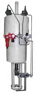
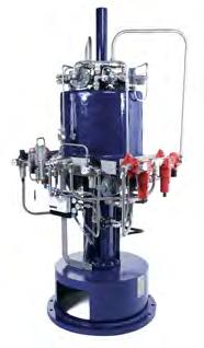
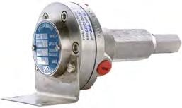
3 PRODUCT RANGE TOP & BOTTOM-GUIDED CONTROL VALVES Our range of high-performance op and boom-guided conrol valves includes single and double-seaed valves suiable for low and high-capaciy applicaions, as well as hree-way valves for mixing or spliing flows. Our conrol valves are designed o faciliae pressure drops a all sages of ransporaion in he oil, gas and power indusries. All valves are refined by our engineers o sui he needs of each applicaion and all service condiions. CAGE-GUIDED CONTROL VALVES The Series 200/7200 range of cage-guided conrol valves is KKI s core produc. The excepional valves in his range combine high-inegriy feaures, such as ASME VIII body/bonne boling design, a high flow capaciy and a wide range of rim designs, from low-noise ani-caviaion o mulisage rims. These valves are ideally suied o he criical service process conrol requiremens of a wide range of indusry applicaions. SURFACE CHOKE VALVES The KKI Series 73 surface choke valve offers a unique soluion for he majoriy of choke applicaions in he oil and gas indusry. The flexible valve design can incorporae many differen rim and body maerial opions o sui differing flow raes and in-service condiions. Thousands of KKI Series 73 surface chokes are insalled around he world on projecs for some of he world s leading oil and gas producion companies. ROTARY CONTROL VALVES The Rorol range of high-capaciy buerfly valves has been developed o overcome he problems associaed wih conrol, caviaion and noise in convenional buerfly valve designs. Ligher in weigh and more compac han globe valve alernaives, his innovaive valve performs especially well in severe-service applicaions, where pressure drops end o be high in he conrolling posiion bu where high-capaciy hroughpus a low pressure drops are also required. SEVERE SERVICE SOLUTIONS For more han 45 years, KKI has buil up a repuaion for delivering valve soluions for he mos arduous service condiions. We have developed a range of advanced, high-qualiy severe service valve soluions for every ype of problemaic applicaion, from high-pressure, high-emperaure environmens o sub-zero emperaures. Our valves are designed o comba he effecs of caviaion, flashing, erosion, conaminaed fluids, corrosion, high velociy, vibraion, noise and energy dissipaion. INSTRUMENTS KKI offers a wide selecion of sophisicaed insrumenaion o suppor our comprehensive range of high-performance valves and acuaors. The insrumens we supply include pneumaic and elecro-magneic posiioners, airses, volume boosers and airlocks. All insrumens are specified o deliver opimum performance for he service condiions and specific needs of each applicaion. We also supply proprieary insrumens o sui individual cusomer preferences. ACTUATORS Our range of robus, versaile and reliable pneumaic acuaors includes he G, C and D Series models. These have been developed o mee he needs of all conrol valve applicaions, offering proven design and high reliabiliy. They are used exensively for on-shore, offshore and power insallaions. In addiion, we supply various proprieary acuaors such as elecric, elecro-hydraulic, pneumaic sepping and hydraulic sepping acuaors o mee cusomer requiremens. All acuaors can be supplied wih hand-wheels and limi sop feaures.


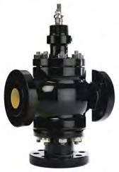
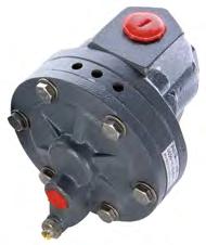
4 TOP & BOTTOM-GUIDED CONTROL VALVES SINGLE SEATED SERIES 0/7 DOUBLE SEATED SERIES 20 3-WAY MIXING AND DIVERTING SERIES 30 CAGE-GUIDED CONTROL VALVES SURFACE CHOKE VALVES ROTARY CONTROL VALVES SERIES 200/7200 SERIES 73 SERIES 60 SEVERE SERVICE SOLUTIONS INSTRUMENTS ACTUATORS SERIES G SERIES C SERIES D


5 02 FOREWORD When considering he applicaion of conrol valves o urbo-compressor ani-surge sysems, he service requiremens are usually beyond he capabiliies of he sandard valves. Off-he-shelf valves are mos unlikely o saisfy he excessive demands of hese applicaions. In hese cases, he required severe service valves need o be individually designed, and collaboraion beween he plan designers, he valve engineer and he operaing engineers is necessary. This paper addresses he unique problems ha exis in he applicaion of conrol valves for compressor ani-surge sysems. I idenifies he naure of hese problems, and provides assisance in he specificaion of he conrol valve ha will be required o overcome he specific service demands. An inroducory guide, i is aimed a engineers wih lile or no previous experience in his aspec of conrol engineering. Furher assisance is available via Koso Ken Inrol, expers in innovaive design echnology and skilled engineering in he severe service valves marke for over 40 years. ED SINGLETON THE AUTHOR Edward ( Ed ) Singleon began his working life as an apprenice in Wes Yorkshire, England in 94. A Charered Engineer, he graduaed wih an Engineering Degree from London Universiy in 950. A few years laer he gained he professional qualificaion of Fellow of he Insiuion of Mechanical Engineers. His experience wih conrol valves exends over he pas six decades. He has been a rue pioneer in he field, founding Inrol Ld in he lae 960s, which laer joined forces wih he Ken Group before being bough by Japan s Koso Group in Ed reired as Managing Direcor in 990 and has aced in he capaciy of Consulan o Koso Ken Inrol since ha ime. Ed also represened he UK on he IEC Inernaional Conrol Valve Sandards Commiee from 990 unil In 995 he was awarded he presigious Cerificae of Meri by he BVAMA for conribuions o conrol valve echnology. His unique experise, buil up from he vas array of world-wide conrol valve projecs on which he has worked, is shared in a series of papers, of which his is he laes. Covering a wide variey of conrol valve opics including oher ailored-specificaion valve uses such as power saion boiler feedwaer sysems and high pressure pump recirculaion services, all of Ed s papers are available from Koso Ken Inrol on reques. February 200

6 CONTROL VALVES IN TURBO-COMPRESSOR ANTI-SURGE SYSTEMS 03 THE APPLICATION OF CONTROL VALVES TO COMPRESSOR ANTI-SURGE SYSTEMS THE PROBLEM OF COMPRESSOR SURGE Pipelines ransporing gases and vapours are invariably dependen on cenrifugal or urbo-compressors for he propulsion of hese fluids. Under normal operaion, wih he compressor running a any consan speed here is a specific relaionship beween he pressure head across he compressor and he flow hrough i. Bu his sable relaionship can be disurbed by sudden changes in flow, pressure and densiy, usually caused by sudden variaions in demand downsream of he compressor or in he case of sysems requiring muliple compressors, a disurbance can be caused by he swiching of compressors in and ou of service. All hese can give rise o formidable pulsaions of pressure and flow, beer known as a surge. Under surge condiions he compressor may run erraically and a siuaion can arise where he pressure build-up in he downsream pipe may overcome he delivery pressure of he compressor, resuling in a flow reversal, reversing he compressor and causing mechanical damage. A surge is usually preceded by small flucuaions, followed by a modes bu very sharp drop in flow, o be followed by a massive drop a he commencemen of he surge. The flow and pressure pulsaions hen, if unchecked, sele down o regular cyclic oscillaions. Surges may also develop a sar-up and whenever he compressor is required o operae during periods of very low flow. Under hese condiions, he compressor finds he flow oo low for conversion o he required discharge pressure. The pressure in he discharge pipe hen exceeds he impeller oule pressure and his siuaion generaes backflow which changes o forward flow when, in he nex phase of he surge, he discharge pressure falls below he impeller oule pressure. This cycle coninues o produce unsable operaion of he compressor along wih excessive vibraion. Seps mus be aken o avoid his dangerous condiion. The usual mehod of prevening his condiion is o include a conrol valve in he discharge line, along wih appropriae insrumenaion o recycle he gas o he compressor sucion line (see figures A and B). This ensures here is always an adequae minimum flow hrough he compressor o mainain operaion above he surge poin. In some sysems, a discharge ven valve is included. This mainains he flow above he surge poin by vening gas from he discharge line in hose insances when here is very lile demand from he downsream process. In pracice, he load changes can happen very quickly so he ani-surge insrumenaion and valves mus have a fas response. Times o ravel from he fully closed o he fully open posiion will vary wih he valve s raed ravel bu, ypically, a valve wih a ravel of 50 mm may be required o open in less han wo seconds and one wih a ravel of 20 mm should open in 0.75 seconds. Obviously a valve wih a shor ravel has an advanage over one wih a long ravel in achieving shor opening imes, and 0.2 seconds has been achieved by shor ravel valves. Jus as imporan as he valve s fas opening is he capabiliy of he valve and is associaed insrumenaion o reac rapidly o small ransien flucuaions in flow and pressure. This subjec will be invesigaed in more deail in he secion Response o ransiens.
7 04 FIGURE A. TYPICAL COMPRESSOR ANTI-SURGE BYPASS SYSTEM SHOWING ALTERNATIVE ANTI-SURGE VENTING SYSTEM DISCHARGE PRESS TRANS FLOW TRANS ANTI-SURGE DISCHARGE VENT VALVE CONTROLLER ANTI-SURGE BYPASS VALVE SURGE DRUM PRESS TRANS VARIABLE SPEED DRIVE COMPRESSOR INLET FIGURE B.. ANTI-SURGE CONTROL SYSTEM ISOLATED FROM PROCESS CONTROL INPUT LINE VARIABLE SPEED DRIVE COMPRESSOR TO COMPRESSOR INPUT LINE OR TO VENT ORIFICE PLATE p p ANTI-SURGE VALVE TRANSDUCER INPUT CONTROL VALVE ANTI-SURGE CONTROLLER PROCESS CONTROLLER FIGURE B. 2. ANTI-SURGE CONTROL SYSTEM INTEGRATED WITH PROCESS CONTROL INPUT LINE VARIABLE SPEED DRIVE COMPRESSOR TO COMPRESSOR INPUT LINE OR TO VENT ORIFICE PLATE p p ANTI-SURGE VALVE TRANSDUCER INPUT CONTROL VALVE ANTI-SURGE CONTROLLER PROCESS CONTROLLER
8 CONTROL VALVES IN TURBO-COMPRESSOR ANTI-SURGE SYSTEMS 05 ANTI-SURGE SYSTEMS In Figures A and B, differen arrangemens of ani-surge insrumenaion are shown, all having he same objecive of insrucing he valve o make he required adjusmens o fluid flow and pressure, in order o preven he onse of surge condiions. I is beyond he scope of his paper o discuss he meris of differen conrol sysems. However i canno be oversressed ha, whaever sysem is used, speed of response of he insrumenaion is jus as imporan as ha of he valve. EFFECTIVE SIZING Effecive raher han accurae is used here inenionally o describe he ar of valve sizing for compressor ani-surge service. The conrol valves specified for mos process conrol applicaions are sized for maximum flow condiions bu, for ani-surge compressor service, he sizing mus address he condiions ha may be conducive o surges a differen flow requiremens and differen compressor speeds. Some of hese facors are conradicory, in sizing erms. Valves on his service have o be able o handle surges in flow above he normal maximum flow required by he process. This may resul in a larger valve han would be required for a normal process conrol applicaion. Then, if he raed ravel of he valve is no excessive, he higher flow/lif relaionship of a larger valve migh offer he added advanage of achieving significan flow changes in a very shor ime. Alhough he bes mehods and daa available may be used, all hese variables, some of which are no very precise, classify he sizing of compressor ani-surge valves as somehing of an ar, raher han an exac science. To undersand he sizing problems, reference should be made o he flow versus pressure curves for he compressor, known as he compressor map (supplied by he manufacurer). Figure 2A is a simplified version of a map divesed of everyhing excep he surge line, he valve sizing line and he pressure delivery curves for various compressor speeds. If he operaing poin falls o he lef of he surge line, he compressor will run ino surge, and if he operaing poin falls o he righ of he surge line he compressor will be operaing under sable condiions. The ani-surge valve should be sized so ha a all compressor speeds he operaing poin is o he righ of he surge line. A working line is someimes drawn on he compressor map indicaing efficiency variaions along each consan speed line. This is no shown in figures 2A and 2B bu, more relevan o valve sizing, an arbirary valve sizing line is shown. This is drawn o he righ of he surge line, mainaining a gap of approximaely 0 o 20% of he surge flow a all speeds. I herefore provides a safey margin agains working condiions crossing he surge line. If a conrol valve (linear characerisic) is sized on he condiions a poin B (figure 2A), he resulan sizing curve will cross he surge line in he region of 75% o 80% of compressor speed, indicaing unaccepable surge condiions a hese speeds and below. If i is decided o use he compressor design poin A as he daum for valve sizing, hen he acual sizing curve will no cross he surge line unil he speed drops o approximaely 35 o 40%. This is an accepable condiion, bu he valve is sized on a very high flow, making i quie large and herefore very expensive. The exra valve capaciy is required a sar-up condiions because of he low pressure drop available for he valve, bu a more economical mehod of making his provision is preferable. Such a mehod is explained in he nex paragraph when he complee compressor map (figure 2B) is considered. FIGURE 2A. SIMPLIFIED COMPRESSOR MAP SURGE LINE VALVE SIZING LINE B COMPRESSOR DISCHARGE PRESSURE SURGE REGIME RECIRCULATIN G ZONE STABLE REGIME A 05% 00% 90% 80% 70% 60% 40% COMPRESSOR SPEED (%RPM) FLOW
9 06 FIGURE 2B. COMPRESSOR PRESSURE/FLOW CHARACTERISTICS (COMPRESSOR MAP) V0,V, V2 θ0,θ, θ2 SLθ0,SLθ = compressor hermodynamic speed (V0= max) = compressor guide vane angle (θ0= max opening) = surge lines for vane seings θ0, θ SL θ2 SL θ SL θ0 VALVE SIZING CURVE FOR θ0 SVL V0 SVLV0,SVLV V0θ0,V0θ,V0θ2 Pand P2 D = surge velociy lines for V0,V = consan speed curves for V and V2a differen vane seings similar symbols apply o VandV2 = compressor inle and delivery pressures = equivalen diameer of compressor inle SVL V SVL V2 P2 V0 θ0 P Vθ0 V0θ V2θ0 Vθ V0θ2 V2θ Vθ2 Volumeric flow a inle DIMENSIONLESS FLOW PARAMETER = ( D 2 x Sonic vel. a inle ) Figure 2B is an example of a complee compressor map including differen hermodynamic speed curves and he effec of differen angles of guide vanes when provided. The X axis represens flow and he Y axis he discharge pressure. For convenience, all erms are expressed in a dimensionless form: Volumeric flow a inle R D 2 Y T M D R M T P P2 Y for he X axis, and = equivalen diameer of he compressor inle = universal gas consan = molecular weigh = emperaure a compressor inle = pressure a compressor inle = pressure a compressor oule = raio of specific heas Cp/Cv P2 P for he Y axis The curved lines indicaed by V0, V, V2 ec are differen hermodynamic speed curves. Each is ploed for a consan value of: V= n x D R Y M T a dimensionless erm This equaion indicaes ha he hermodynamic speed is influenced by he speed of roaion of he urbine (n) and he molecular weigh and emperaure of he fluid.

10 CONTROL VALVES IN TURBO-COMPRESSOR ANTI-SURGE SYSTEMS 07 Considering each consan speed curve, and moving from a high o a low flow condiion, i will be noed ha P2/P increases unil a poin is reached, a he surge line, where he discharge pressure raio P2/P sars o decrease. This is represened in figure 2A, bu in realiy he curves would sar o be irregular afer passing he surge line. A his poin he flow becomes unsable and he compressor goes ino surge. For differen V curves (differen values of one or all of n, T, Y and M), here will be a differen poin on he compressor characerisic diagram where surge begins. Joining hese poins on each V curve gives he compressor surge line. The area o he lef of his line is known as he surge regime and o he righ he sable regime. If he compressor, hrough a sudden drop in demand from he process, should be consrained o operae in he surge regime i could, as already explained, susain damage. Some compressors are equipped wih moveable inle guide vanes for addiional flow regulaion (figure 2B). To simplify figure 2B, he consan speed curves have no been exended ino he surge regime. Differen guide vane angles, θ0, θ, θ2, change he geomery of he compressor and his changes he V versus P2/P relaionship. For each V curve here is a relaed q curve, i.e. V0θ0, Vθ, V2θ2 and each will have a differen surge poin. Joining hese surge poins gives surge lines SLθ0, SLθ, SLθ2 for each guide vane angle. Wih increasing angles of he guide vanes, he surge lines move o he lef of he char, demonsraing ha lower flows can be acceped before he surge mode is experienced. Changes in fluid emperaure, molecular weigh and o a lesser exen Y, produce changes in he hermodynamic speed V, alhough he compressor may be running a a consan speed. An increase in emperaure will produce a reducion in V (on he char, perhaps from V0θ0 ovθ0) and his gives a lower surge poin. Similarly, an increase in molecular weigh will produce an increase in V (on he char, perhaps from V2θ0 o Vθ0 ) and his produces a higher surge poin. Any such variaions in working condiions mus be aken ino accoun when sizing he conrol valve. To avoid surge condiions, he ani-surge valve mus sar o bypass flow jus before any reducions in flow mee he surge line corresponding o he hermodynamic speed. The valve sizing line faciliaes his requiremen. I may be beween 0% and 20% of he surge flow for each value of P2/P and for each value of θ, bu he narrower he gap beween he surge line and he valve sizing line, he smaller he valve and hence he lower he cos. Unforunaely all aemps o economise on valve size have o be abandoned when he mos serious cases of surge are aken ino accoun. Under hese condiions he valve may be called upon o recycle or ven he maximum capaciy flow of he compressor. To make provision for hese condiions, one acceped pracice is o make an iniial calculaion of he valve size or he valve raed Cv (see he appendix for he definiion of Cv). To make his calculaion he operaing daa, noably he valve pressure drop and he flow, exising a he poin of inersecion of he 00% speed curve wih he surge line, is used. This calculaed Cv is hen muliplied by 2.2 o arrive a he required valve maximum Cv. The 2.2 is an empirical figure esablished hrough pracical ess. Alernaively, he operaing daa a he poin of inersecion of he 00% speed curve wih he valve sizing line may be used and he calculaed Cv muliplied by.8.
11 08 VALVE FLOW-LIFT CHARACTERISTIC All conrol valves have a relaionship beween he flow and he lif or ravel of he plug from he valve sea wih he pressure drop across he valve remaining consan. The wo mos frequenly used characerisics are linear and equal percenage. The linear characerisic is self explanaory. The equal percenage has an almos exponenial relaionship beween flow and lif. Linear characerisic is more commonly used in urbo-compressor bypass sysems because of is rapid increase in flow a low lif, bu equal percenage is also used on occasions. On rare occasions, in order o ensure ha he ani-surge valve operaes effecively as near o he surge line as possible, special flow/lif characerisics are designed. RANGEABILITY The valve rangeabiliy required for each applicaion depends on he maximum and minimum Cv as deermined from he valve sizing line o he righ of he surge line on he compressor characerisic char (figures 2A and 2B). High performance conrol valves offer rangeabiliies varying from 45: o 00:. These are adequae for he majoriy of insallaions bu higher rangeabiliies can be achieved for excepional applicaions. FIGURE 3. TRACES INDICATING THE TRANSIENT DROP IN FLOW PRECEDING THE PRESSURE SURGE CYCLES p ACROSS COMPRESSOR % SURGE FLOW MEASURED AT COMPRESSOR INLET% ELAPSED TIME (SECONDS)
12 CONTROL VALVES IN TURBO-COMPRESSOR ANTI-SURGE SYSTEMS 09 SPEED OF RESPONSE TO SUDDEN PROCESS DISTURBANCES Sudies of gas and vapour surges in urbo-compressor sysems reveal ha he acual ampliudes of he pressure pulsaions are less han he values obained from calculaions using he measured ampliudes of he flow pulsaions. A simple relaionship beween he wo is herefore non-exisen. As will be seen from figure 3, which is a synhesis of resuls from a number of ani-surge sysems, he precursor o a surge is an exremely rapid fall in flow followed by a much greaer fall a he acual surge. From a conrol poin of view, he difficulies arise wih he speed a which hese flow changes and relaed pressure changes ake place. The ime elapse from he firs indicaion of a surge o he firs major flow reversal can be less han 0.07 seconds (see Figure 3). The insrumenaion mus be able o deec hese fas process changes bu, equally, he conrol valve mus be capable of following hese insrucions. This calls for sroking imes (closed o open) in he region of 0.5 o 3.0 seconds depending on he lengh of he valve sroke. Speeds of his order can be achieved wihou overshoo using, in he case of pneumaic acuaors, high capaciy volume boosers (relays ha increase he rae a which a valve posiioner can apply air o he acuaor). In mos cases only fas opening is required; he closing sroke may ake place a a slower speed. A fas sroking speed does no of iself ensure he valve s insan response o ransien disurbances affecing a conrol sysem. The abiliy of a valve o mee his requiremen can be esed in a number of ways, he wo mos imporan being: a) The applicaion of sep change signals b) The applicaion of sinusoidal signals a varying frequencies, he resuls being ploed on a Bode diagram. These wo procedures are described briefly in he nex wo secions. For a complee explanaion, refer o he appendix. STEP INPUTS This form of performance esing involves, as is name implies, he applicaion of sep inpus o he conrol valve/acuaor assembly and he measuremen of he valve s response. Resoluion, dead band, dead ime and sep response ime are he imporan performance facors ha can be gleaned from his es. In dynamic esing, a conrol valve wih is acuaor and posiioner behaves in a similar manner o a single capaciy sysem and can herefore be represened by a firs order differenial equaion. In applying such an equaion o invesigae he dynamic performance of a conrol valve he unis of he inpu signal mus be compaible wih he unis of he valve response, QO and qo. In his case he response is valve ravel. The inpu mus herefore be convered from is insrumen unis o he equivalen valve ravel unis of lengh. This can be accomplished by a conversion equaion. Symbols I = maximum inpu signal insrumen unis i2 = inpu signal a ime = 0 insrumen unis i = inpu signal a ime insrumen unis Qs = maximum inpu signal (I convered) valve unis (mm) Qo = maximum valve response (max. ravel) valve unis (mm) qoo = valve response (ravel) a ime = 0 valve unis (mm) qo = valve response (ravel) a ime valve unis (mm) qi = inpu signal a ime (i convered) valve unis (mm) s = ime a which seady sae condiions have been achieved seconds = ime consan seconds A seady sae condiions ( = s), I is equivalen o Qs. A = 0, i2 is equivalen o qoo. For inermediae imes (beween = 0 and = s), he value of he valve unis qi equivalen o i may be calculaed from: [ ] (Qo - qoo) qi = x (i - i2) + qoo (I - i2) Represening he valve acuaor and posiioner uni by a firs order differenial equaion: d(qo - qoo) + d (qo - qoo) = Qs he soluion o his equaion is: - (qo - qoo) = (Qs - qoo) + Ae (for he complee soluion of (2), see appendix) when = 0, qo = qoo, herefore A = - (Qs qoo) () (2) hence a any ime he fracional change made (FCM) is: qo - - qoo FCM = = -e Qs - qoo (3) when equals he ime consan qo - qoo FCM = = Qs - qoo - ( 2.78) = (4)

13 0 This indicaes ha he ime consan for he valve assembly can be found from he race of he valve response o he sep inpu. The ime consan is defined as he ime required for he response o reach 63.2% of is final value. When is large compared wih, he response qo will have reached is maximum value Qo. Equaion (3) hen becomes Qo - qoo Qs - qoo and so, a seady sae condiions, Qo = Qs In realiy, he valve ravel a seady sae condiions may fall slighly shor of he valve s raed ravel due o fricional effecs which creae dead band and hyseresis. Similarly, if Qs is based on he valve s raed ravel, hen Qo may fall slighly shor of Qs. The ime consan however, by definiion is 63.2% of he response s achievable final value, which is he slighly reduced Qs. This sligh discrepancy is usually ignored as i has pracically no meaningful effec on he process performance calculaions requiring he sep response daa. If, in seing up he es, i is found ha he achievable maximum response o he maximum sep inpu is slighly less han he valve raed ravel, and his achievable ravel is hen used for Qo and also for he calibraion of he inpu signal raher han he raed ravel, Qo should hen equal Qs under seady sae condiions. = TIME CONSTANT The ime consan is required in calculaions of he dynamic performance of process conrol loops involving conrol valves. Typical values of he ime consan for ani-surge sysem valves are from 0.32 o 2.25 seconds. I is a direc indicaion of he speed a which a conrol valve can reac o rapid changes in conrol signals. STEP RESPONSE TIME A furher deail concerning he dynamic performance of a conrol valve is he sep response ime. This is defined as he inerval of ime beween he iniiaion of an inpu sep change and he momen he oupu reaches 86.5% of is final seady sae value. This measure of performance herefore akes accoun of he dead ime before response. In some procedures for calculaing he dynamic characerisics of process sysems he sep response ime of he valve plays a major role. The sep response ime can be found from he plo of he sep response es. The procedure for sep inpu esing and he possible measuremens are described in much greaer deail in he ISA echnical repors in reference 6.
14 CONTROL VALVES IN TURBO-COMPRESSOR ANTI-SURGE SYSTEMS BODE PLOTS (SINUSOIDAL INPUT) The Bode plo gives some addiional informaion concerning he dynamic performance of a valve, no obainable from he sep inpu es. The Bode plo represens he response of he valve o he inpu of a small ampliude sinusoidal signal of specified frequency. This is applied a wo or hree poins wihin he raed ravel of he valve (possibly 25%, 50%, 75%), he ampliude being plus or minus 5% for valves wih raed ravels no exceeding 70 mm. For valves wih higher raed ravels he ampliude may be less han 5%. Separae ess are carried ou a differen poins wihin he valve raed ravel and a differen frequencies of he inpu signal. The ampliude raio for each of hese ess is measured and recorded. Oher measuremens which can be made are he wavelenghs and he phase lag of he response wave. The aenuaion in decibels is ploed on he naural scale agains frequency, which is ploed on he log axis of a semi-log char. On he same char he phase lag is also ploed on he naural scale agains frequency (see figure 4). In he following example of a firs order differenial equaion represening he valve s response o sinusoidal inpus, he elapsed ime commences a he beginning of a cycle under seady sae condiions. The inpu and response are expressed as percenages of heir maximum values (i.e. % of Qi and % of Qo ). The aenuaion is calculaed in decibels. db = 20log0 Qo Qi FIGURE 4. BODE DIAGRAM. SOME TYPICAL RESULTS FROM TESTS ON A 300 MM VALVE OPERATED BY A PISTON ACTUATOR WITH AN ELECTRO-PNEUMATIC POSITIONER DEVIATIONS FROM IDEAL RESPONSE CORNER FREQUENCY C PHASE LAG DEGREES EQILIBRIUM INPUT AMPLITUDE 8mA, 2mA, 6mA EQUATING TO 25%, 50%,75% OF RATED TRAVEL. STIMULUS AMPLITUDE + & -.0mA,.5mA, 2.0mA (IN THE INTEREST OF CLARITY, THE CURVES REDRAWN HERE ARE FROM THE MEDIAN OF THESE TESTS) ATTENUATION DECIBELS STIMULUS FREQUENCY Hz
15 2 SINUSOIDAL INPUT SYMBOLS Qi = maximum value of sinusoidal inpu (00%) qi = value of inpu a ime, qi = Qi sinw (% of Qi) f = frequency of inpu = /T (s - ) = w/2π = frequency of response under seady sae condiions fc = corner frequency (s - ) = ime consan for valve assembly = /2πfc (s) T = periodic ime of inpu signal and of response under seady sae condiions (s) T = 2π/w (s) = elapsed ime from beginning of each cycle under seady sae condiions (s) a = angle of lag of response under seady sae condiions (radians or degrees) a = an - w (s) Qo = maximum response (00%) when (w - a) = π/2 qo = response a ime (% of Qo) a ime = 0 (seady sae condiions esablished) qi = 0 and qo = - a ime = a w w 00x ( ) = an - w w +(w) 2, q0 = 0 % of Qo As explained in he secion dealing wih sep inpus, a conrol valve wih is acuaor and posiioner reacs in a similar manner o a single capaciy process. The firs order differenial equaion represening he dynamic response of a single capaciy process o he applicaion of a sinusoidal inpu is: dqo + qo = Qi sinw (5) d SOLUTION BY THE FREQUENCY RESPONSE METHOD, AVOIDING INTEGRATION Rewriing equaion (5) in is ransformed version for a firs order differenial equaion where d/d is replaced by he complex variable s, gives he ransfer funcion of he sysem. Qo Qi = The seady sae soluion o he equaion for a single capaciy sysem wih a sinusoidal inpu is saisfied by subsiuing jw (or j2πf) for s in he ransfer funcion. j = ( ) Qo Qi + s The modulus of his complex number gives he ampliude raio Qo/Qi and he argumen gives he phase lag a. Qo Qi = = + j2πf + (2πf) 2 and, by definiion he gain or aenuaion is aenuaion = 20log phase lag a = an - 2πf a = an - (-2πf) + (2πf) 2 radians decibels decibels when a = π/4, f = fc, = 2πfc and = where fc is he corner frequency (see Figure 4). 2πfc (6) (7) (8) Qo 20log Qi (9) (3) This ype of equaion can be solved in a number of ways, he principal ones being frequency response and direc inegraion. Since he conrol valve assembly behaves like a single capaciy process, he aenuaion curve can be reproduced by exending a line from he corner frequency in figure 4, downwards wih a slope of 6 db per ocave of frequency. In acualiy, as es resuls will show, he aenuaion curve does no connec wih he 0 db aenuaion line he slope sars o decrease a aenuaion values beween 4 and 5 db, crossing he corner frequency line a 3 db and is progress owards he 0 db line is hen asympoic. These condiions are for a heoreical single sage capaciy process. Valves, alhough hey are considered o be single capaciy sysems, do have presen some idiosyncrasies, causing he acual aenuaion curve o deviae slighly from he ideal. In compressor ani-surge applicaions, i is highly desirable for he phase lag curve o be locaed owards he righ on he Bode diagram where i regisers higher frequencies. This gives a higher corner frequency and a lower ime consan wih faser valve acion and a shor phase lag. Full deails of he soluions o he differenial equaion represening he response of a single capaciy sysem o a sinusoidal inpu, using he frequency response and he inegraion mehods, can be found in he appendix.
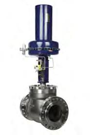
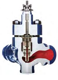
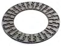
16 CONTROL VALVES IN TURBO-COMPRESSOR ANTI-SURGE SYSTEMS 3 NOISE AND VIBRATION Alhough compressors have a high poenial for noise generaion, he manufacurers are required o comply wih noise limiaions se by he plan designers and healh and safey auhoriies. By he same oken he ani-surge valve mus comply wih similar noise limiaions and mus have he abiliy o conrol high pressure gas sysems wih he minimum of noise and vibraion. Some ypes of vibraion can be he resul of mechanical problems, bu generally on hese sysems vibraion is aribuable o aerodynamically generaed noise, caused by unconrolled high fluid velociy which, if unconrolled, may se up serious vibraions in he adjacen pipework. The compressor ani-surge service requires he conrol valve o reduce high pressures o very low pressures, he P/P2 raio being in excess of wo, noing ha pressure raios of 7.5 are someimes needed. Sonic velociy is produced by a P/P2 raio of approximaely 2: and his is usually noisy: higher raios produce supersonic velociies wih resulan shock waves and hese are very noisy. Convenional single sage conrol valves on compressor recycle applicaions have been known o emi noise levels in excess of 22 dba measured a mere downsream and mere from he pipe. For a single sage pressure reducion (compressible fluid), he rim exi velociy is proporional o = (refer o figure 5A). 2 x enhalpy drop 2 x (H H2T) From his enhalpy/enropy char i can be seen ha if he pressure drop is divided ino a number of sages, each wih an enhalpy drop of approximaely H H2, he je velociy a he rim exi and any par wihin he rim will be reduced and, wih a sufficien number of sages, he velociy levels can be resriced o somehing well below sonic, resricing noise levels o 85 dba or less. SOME PRACTICAL SOLUTIONS A valve capable of his ype of performance is he mulisage valve which incorporaes he concenric muli-sleeve rim, as shown in figure 6. The rim consiss of a number of sleeves which are drilled wih small holes of varying size. There are annular gaps beween each sleeve and, wihin hese gaps, spacers divide he holes ino separae rows. The gaps allow parial pressure recovery beween each discree sage and he holes do no coincide from one sleeve o anoher. Thus, he fluid is consrained o flow hrough he holes and, in he annular gaps, i mus change direcion wice before enering he holes in he nex sleeve. This means ha a rim wih four discree sages has a furher six pressure reducion sages hrough he urns beween each sage. Ideally, he rim should be specially designed for each service bu, in general, i is desirable o resric he je velociy a he firs sage o no more han a Mach number of 0.70 and o reduce his hrough each successive sage unil he las one, where he je velociy is preferably no higher han 0.45 Mach. For effecive noise reducion he holes should no exceed 4 mm in diameer, wih 3 mm he preferred size. Experience suggess ha here can be flexibiliy in he arrangemen and size of he holes; a device ha can be useful in giving he valve a purpose designed flow/lif characerisic. An addiional feaure of his design is is abiliy o handle fluids conaining paricles of foreign maer wihou blockage. Experience suggess ha o avoid vibraion problems in he downsream piping he fluid velociy in he valve oule secion should no exceed Mach 0.3. Low noise rims mus also include design feaures o avoid mechanical vibraion which could resul from he impac of high velociy jes and urbulen fluid. Mechanical clearances in plug and sem guides mus be carefully deermined o avoid laeral vibraion whils recognising he effecs of emperaure changes. Eliminaion of any axial vibraion of he plug and sem assembly is provided by he pressure balanced plug design. Besides equalising pressures above and below he plug he design incorporaes a balancing seal which impars a damping acion o discourage any endencies owards axial vibraion. Powerful acuaors also assis owards axial sabiliy of he valve plug.
17 4 FIGURE 5A. ENTHALPY/ENTROPY CHART, ILLUSTRATING THERMODYNAMIC CHANGES THAT OCCUR WITH COMPRESSIBLE FLOW THROUGH A SINGLE STAGE VALVE AND A MULTISTAGE VALVE WITH THREE STAGES AND FOUR PATH TURNS H ENTHALPY P P2 H H2 T T2 VALVE OUTLET PRESSURE VENA CONTRACTA TEMP STAGE STAGE 2 VC ACTUAL ENTHALPY DROPS FOR VALVE WITH THREE STAGES AND FOUR TURNS ACTUAL ENTHALPY DROP FOR SINGLE STAGE VALVE ADIABATIC-ISENTROPIC EXPANSION H2T STAGE 3 ENTHALPY DROP WITH THREE STAGES = H H2 ENTHALPY DROP WITH ONE STAGE = H H2T ENTROPY S FIGURE 5B. ENTHALPY/ENTROPY CHART, ILLUSTRATING COMPRESSIBLE FLOW THROUGH A LABYRINTH TYPE CONTROL VALVE. THE ACTUAL POLYTROPIC EXPANSION () IS PRODUCED WITH A LARGE NUMBER OF TURNS IN THE FLOW PATH AND (2) WITH A SMALLER NUMBER H ENTHALPY P P2VC P2 2 THE THEORETICAL ISOTHERMAL EXPANSION WOULD BE PRODUCED BY AN INFINITE NUMBER OF TURNS THEORETICAL EXPANSION ACTUAL EXPANSION ENTROPY S
18 CONTROL VALVES IN TURBO-COMPRESSOR ANTI-SURGE SYSTEMS 5 FIGURE 6. MULTI-STAGE CONTROL VALVE WITH FOUR DISCRETE STAGES AND SIX TURNS OF FLOW PATH (Couresy of Koso ken Inrol Ld)


19 6 Anoher ype of mulisage rim is illusraed in figure 7. This is generally known as he labyrinh rim because i consiss of a number of discs sacked on op of each oher, each disc having eched or milled ino one side a large number of small flow passages. The passages have a varying number of righ angle urns and he flow area increases from he inle o he oule. The working principle is similar o he concenric sleeve design bu here are no significan gaps beween sages and here is herefore no significan pressure recovery. The design, because of heigh of he sacked discs o give he required Cv, demands a longer raed ravel han he concenric sleeve design, so greaer aenion has o be made o he provision of fas opening. As will be seen from figure 5b, he greaer number of urns available in his design reduces he enhalpy drop mos effecively, so very low je velociies can be achieved. The number of urns is deermined wih he inenion of resricing he fluid velociy wihin he rim o somehing beween 0.5 and 0.3 Mach. To accommodae a sacked disc design wih a large number of urns, a larger valve body may be required and, wih a large number of discs, he acuaor will require a longer sroke. The ani-vibraion design feaures of his valve are very similar o hose of he concenric sleeve design. Boh he concenric sleeve and he labyrinh low noise valves have a proven record on compressor ani-surge sysems. LEAKAGE IN CLOSED POSITION In some processes, he compressor ani-surge valve, under normal plan operaion, is se up o come ino operaion a 20 o 30% of he maximum flow. This ensures sable compressor operaion bu i does no necessarily aver surges and i is cosly on energy. A recycling valve used in his way does no need o have igh shu-off. IEC Class II (ANSI/FCI 70-2 Class II) is adequae. The preferred mehod of operaing a recycling valve is o mainain he valve in a closed posiion unil he insrumenaion deecs ha he compressor is operaing quie close o he surge line (figure 2A). The valve is hen commanded o open quickly. During he periods of sable operaion, when he valve is required o remain closed, very igh shu-off is required. The maximum limis se by IEC Class IV and Class V (ANSI/FCI 70-2 Class IV and Class V) can be achieved wih meal-o-meal seaing and, depending on service condiions, a resilien sea design is available o achieve a shu-off leakage beer han Class V. FIGURE 7. TORTUOUS PATH (LABYRINTH) TYPE VALVE THERE ARE A NUMBER OF VARIATIONS BASED ON THIS PRINCIPLE DETAIL OF FLOW PATHS SHORT DISC STACK ILLUSTRATED HIGHER CV ACHIEVED BY ADDING DISCS INCREASING HEIGHT STACKED DISCS
20 CONTROL VALVES IN TURBO-COMPRESSOR ANTI-SURGE SYSTEMS 7 ACTUATOR In compressor recycle services for surge proecion, fas sroke speeds are imporan. Acuaors can be designed and fied wih relays ha will achieve he required speeds. The concenric sleeve design does no have a high raed ravel so he reducion in ime o sroke he valve from he closed o he fully open posiion is no such a difficul ask as wih some low noise valves ha have a longer valve ravel. Opening quickly is essenial. As saed in he speed of response secion, opening imes can be very shor. For example 0.5 o 2.0 s can be achieved for shor ravel valves and.5 o 3.5 s for longer ravels. Acuaors are invariably of he pneumaic power cylinder ype, working wih air pressures in he range from 350 kpa.g o 750 kpa.g. Normally, ani-surge valves are required o open in he even of failure of he acuaor operaing supply bu, occasionally, in hose sysems where he valve is consanly recycling a porion of he process fluid, he valve may be required o lock in he posiion in which i was operaing a he insan of he failure. EXAMPLES OF CONTROL VALVES SPECIFIED FOR COMPRESSOR ANTI-SURGE SERVICES Unless oherwise saed pressures are absolue. APPLICATION. CONCENTRIC SLEEVE VALVE Service condiions a 2 poins along he agreed valve line were he basis for Cv and noise calculaions o ensure he valve provides adequae proecion hroughou he full range of compressor speeds and gas flows. This ypical example is for he maximum flow condiion: SERVICE CONDITIONS Fluid Flow Molecular Weigh Hydrocarbon Gas 73,000 kg/hr 9.70 kg/kg mol Specific Hea Raio.25 Flowing Temperaure Inle Pressure Downsream Pressure Upsream Piping Downsream Piping Leakage in closed posiion o be saed Acion on air failure Time for full opening sroke Noise a m mus no exceed 30 C 2.55 x 0 3 kpa.38 x 0 3 / 0.93 x 0 3 kpa 500 mm sch 60 wall hickness mm 500 mm sch 60 wall hickness mm no o exceed ANSI/FCI 70-2 Class V valve opens no o exceed 2.6 s 85 dba A valve wih he following specificaion qualifies for hese service condiions.
 VALVE SPECIFICATION Globe syle valve Valve inle 300 mm Valve oule 300mm Body raing ANSI Class 600 Body maerial Cas Inconel ASTM A494 CW-6MC76 Inle connecion Flanged ANSI 600 Oule connecion")
21 8 APPLICATION. (CONT D) VALVE SPECIFICATION Globe syle valve Valve inle 300 mm Valve oule 300mm Body raing ANSI Class 600 Body maerial Cas Inconel ASTM A494 CW-6MC76 Inle connecion Flanged ANSI 600 Oule connecion Flanged ANSI 600 Trim Raed Cv of valve Concenric sleeve design wih hree discree sages (seven pressure reducion sages) seal balanced plug wih heavy secion PTFE seal 450 (= Kv) Rangeabiliy 85: Trim maerial Inconel 625 wih sellie facing Leakage flow in closed posiion wihin IEC Class V (ANSI/FCI 70-2 Class V) Power conversion a maximum flow Noise predicion a max flow Acuaor Time for full opening sroke Acion on air failure 2.44 Mw 82.5 dba a m downsream and m from pipe Pneumaic power cylinder, size 200, double acing.8 secs valve opens This valve is similar o a Norh Sea plaform applicaion where NACE maerial compliance is required. The sour gas services involved in he Norh Sea operaions are an example of difficul applicaions requiring a sound knowledge of compaible maerials.
22 CONTROL VALVES IN TURBO-COMPRESSOR ANTI-SURGE SYSTEMS 9 APPLICATION 2. LABYRINTH VALVE SERVICE CONDITIONS Four ses of operaing condiions were given wo are quoed here. CASE. Compressor speed 22% Flow Temp SCMH 33 C MW 24.6 P,20 kpa P2 Calculaed Cv Max allowable opening ime 293 kpa 895 US unis (=774 Kv) 2.5 s CASE 3. Compressor speed 50% Flow Temp SCMH 33 C MW 24.6 P 493 kpa P2 Calculaed Cv 348 kpa 2,085 US unis (=,804 Kv) VALVE SPECIFICATION Valve body syle Valve size Trim Raed Cv Valve ravel Time for opening Power conversion a maximum flow Noise predicion a max flow Acuaor Air failure acion Angle valve 455 x 60 mm Sacked discs wih labyrinh flow pahs 22 urns 2,80 US unis (=,886 kv) 50 mm 2.0 s.65 Mw 8.0 dba a m downsream and m from pipe pneumaic double acing cylinder wih elecro/pneumaic posiioner and volume boosers valve opens


23 20 CONCLUSIONS The conrol valve is, compared wih he insrumenaion, a slow developer. New design feaures have been incorporaed over he years bu no a he rae or he degree of innovaion affecing he insrumens ha measure he process changes and command he valve o ake he correcive acion. However, for he applicaions engineer, he conrol valve presens in some ways greaer difficulies han he insrumenaion when aemping o prescribe he ideal specificaion for severe services such as compressor ani-surge bypass. The valve is a he business end of he conrol sysem and has herefore, nex o he acual compressor, he mos responsible role. I has he direc and final effec on he fluid being conrolled. I is unusual for he same working condiions o be repeaed from one plan o anoher, so he valves are o a grea exen ailor-made for each applicaion. Such valves are expensive single unis of plan and i is herefore imperaive ha he applicaion engineering is of he highes order since misakes can only come o ligh afer he plan sar-up and subsequen correcive acion can be very expensive for all paries. Some of he consideraions necessary, before a conrol valve can be specified for compressor bypass service, have been oulined in his paper which, for he mos par, has been wrien a a basic level for hose no oo familiar wih conrol valve echnology. Thanks are exended o Dr J. T. Turner for correcing he proofs and making some valuable suggesions.

24 CONTROL VALVES IN TURBO-COMPRESSOR ANTI-SURGE SYSTEMS 2 APPENDIX The appendix includes he fundamenal definiions of he valve sizing coefficien Cv (Kv), he flow/lif characerisic and he pressure recovery facor FL. For he benefi of hose who are no longer familiar wih he soluion of differenial equaions and don have heir mahs books o hand, bu are curious o know he mehods used o arrive a he resuls, hese are reproduced in he appendix. Cv and Kv These are he valve flow coefficiens used o simplify he sizing equaions (see references 8 and 9). The only difference beween he wo is in he unis chosen for he service condiions. The definiion for Cv is he flow in US gallons per minue of waer a 60 F, wih a pressure drop across he valve of psi (6,895 pa). The unis of Cv are herefore US gallons/minue. The definiion for Kv is he flow in cubic meres of waer a 0.6 C wih a pressure drop across he valve of bar ( x 0 5 pa). The unis of Kv are herefore cubic meres/hour. I will be seen from references 8 and 9 ha hese flow coefficiens, alhough based on liquid flow, are used in sizing equaions for gases and vapours, made possible by he inroducion of an expansion facor. The procedures for esing valves o allocae Cv and Kv values can be found in reference 0. FL This is ermed he pressure recovery facor. I allows he pressure recovery, which usually akes place beween he vena conrac and he valve oule, o be applied when sizing valves operaing above he criical pressure drop. For normal flow condiions he pressure recovery is included in he valve Cv and Kv (see references 9 and 0). Flow/lif characerisic Assuming here is a consan pressure drop across i, a conrol valve has a predeermined relaionship beween he fluid flowing hrough i and he amoun of he valve opening, usually ermed he lif. This relaionship, or characerisic, depends on he design of he valve plug and sea, known collecively o valve engineers as he rim. The mos imporan feaure is he way in which he orifice area varies wih he valve lif. The wo mos frequenly used characerisics in process conrol are linear and equal percenage. As is name implies, he linear characerisic gives a linear relaionship beween flow and lif, whils he equal percenage gives an exponenial relaionship such ha a any poin in he valve lif, a furher incremenal increase in he lif gives an equal percenage increase in flow (see reference ).
25 22 SOLUTION OF THE DIFFERENTIAL EQUATIONS STEP INPUT CHANGE Soluion of he differenial equaion. (The key o he symbols is in he main ex.) d(qo qoo) d + (qo qoo) = Qs d(qo qoo) + d (qo qoo) Qs muliply each side by he inegraing facor = e d = e e d(qo qoo) d Qs + e = e his can be rewrien as: d d e (qo - qoo) = [ ] Inegraing e (qo - qoo) = Qs e (Qs - qoo)e d + A A is a consan of inegraion - - (qo - qoo) = e (Qs - qoo)e d + Ae - - (qo - qoo) = e (Qs - qoo) e + Ae - (qo - qoo) = (Qs - qoo) + Ae when = 0 qo = qoo 0 = (Qs - qoo) + A A = (Qss - qoo) - (qo - qoo) = (Qs - qoo) (Qs - qoo) e FCM = (qo - qoo) (Qs - qoo) - = e = fracional change made When = FCM = For a single capaciy process he ime consan is he ime required for he response o reach 63.2% of is final value.
26 CONTROL VALVES IN TURBO-COMPRESSOR ANTI-SURGE SYSTEMS 23 SOLUTION TO THE EQUATION BY THE FREQUENCY RESPONSE METHOD SINUSOIDAL INPUT SIGNAL Symbols as shown in he ex. dqo d + qo Qi sinw (5) Rewriing equaion (5) in is ransformed version for a firs order differenial equaion where d/b is replaced by he complex variable s gives he ransfer funcion of he sysem. Qo Qi = + s (6) The seady sae soluion o he equaion for a single capaciy sysem wih a sinusoidal inpu is saisfied by subsiuing jw (or j2π) for s in he ransfer funcion. j = ( ) Qo Qi = + j2πf To arrive a he required soluion his complex number mus be divided ino is real and imaginary pars. (7) Qo Qi = x + j2πf - j2πf - j2πf = + (2πf) 2 - j2πf = + (2πf) 2 2πf j + (2πf) 2 The modulus of his complex number gives he ampliude raio Qo/Qi and he argumen gives he phase lag a. Qo Qi = + (2πf) 2 (8) a = an - (-2πf) and, by definiion he gain or aenuaion is 20log decibels Qi Qo aenuaion = 20log + (2πf) 2 decibels (9) phase lag a = an - 2πf radians (3) when a = π/4, f = fc, = 2πfc and = where fc is he corner frequency (see Figure 4). 2πfc
27 24 SOLUTION OF THE DIFFERENTIAL EQUATION BY INTEGRATION SINUSOIDAL INPUT SIGNAL The key o he symbols is in he main ex. dqo d + qo Qi sinw dqo qo + = d Qi sinw muliplying hroughou by he inegraing facor e d = e e dqo Qi + e qo = e sinw d his can be wrien as: d = d e Qo [ ] Qi sinw e e qo = rewriing Qi e sinw d + A Qi qo = - e - e sinw d + Ae For seady sae condiions is large compared wih and he las erm hen diminishes o almos zero and may be ignored. Under hese condiions he response (he valve) oscillaes a he same frequency as he inpu bu no in phase. I will lag behind he inpu a an angle a = an - w = an - 2πf. A consan frequency he phase lag is consan. (a) The inegral can be solved by using inegraion by pars rewriing o faciliae inegraion by pars Qi qo = - e e (sinw) d [ ] u.dv = uv + vdu making u = e ; dv = sinw; v = - cosw and inegraing he bracke w -e cosw + cosw e d w w inegraing again and making u = e e ; dv = cosw d; v = sinw w w -e w e e cosw + sinw - sinw w 2 2 w 2
28 CONTROL VALVES IN TURBO-COMPRESSOR ANTI-SURGE SYSTEMS 25 SOLUTION OF THE DIFFERENTIAL EQUATION BY INTEGRATION (CONT D) SINUSOIDAL INPUT SIGNAL rewriing [ ] e sinw d = e sinw - cosw - w w w 2 e sinw d rearranging e sinw d = since e w 2 2 (sinw - w cosw) + ( w ) 2 sina an a = w = and cosa = his can be simplified o: cosa + w 2 2 (sinw cosa - cosw sina) sin(w - a) e sinw d = e = e + w w 2 2 his can be subsiued in equaion (a) for he inegral erm, giving: qo = Qi sin(w - a) + w 2 2 When (w a) = π/2, qo = Qo, so he ampliude raio is: Qo Qi = = + w (2πf) 2

29 26 REFERENCES AND BIBLIOGRAPHY. R.A.Srub Ani-surge regulaion for compressors, published by Brown Boveri-Sulzer Turbomachinery Ld. 2. A.S.Clark Evaluaion of a conrol valve for ani-surge conrol sysems, published by Briish Gas Engineering Research. 3. N.Saroselsky Improved surge conrol for cenrifugal compressors, published by Chemical Engineering. & L. Ladin 4. O.Kneisel The frequency response mehod as a means of analysis of conrol problems in process indusries, published by Hammel-Dahl Co. 5. T.Fugia, T.Kagawa Disurbance characerisics of conrol valve posiioners, & M.Kuroda published by ISA Process Measuremen & Conrol Division ANSI/ISA Tes procedure for conrol valve response measuremen from sep inpus, ANSI/ISA Conrol valve response measuremen from sep inpus, ANSI/IS , published by ISA, PO Box 2277, Research Triangle Park, NC E.W. Singleon The role of he conrol valve in improved process conrol, published by ABB Conrol Valves. Reprined from Valve World, volume 4, Issue 5, Ocober IEC Conrol valve erminology, IEC Sandard , published by Commission Elecroechnique Inenaionale, 3 Rue devarembé, Case posale 3, 2 Genève 20, Suisse. 9. IEC Conrol valve sizing equaions, IEC Sandard IEC Conrol valve flow capaciy es procedures, IEC Sandard IEC Conrol valve inheren flow characerisics and rangeabliy, IEC Sandard IEC Conrol valve inspecion and rouine esing, IEC sandard ANSI/FCI Conrol valve sea leakage, ANSI/FCI sandard E.W. Singleon The derivaion of he IEC/ISA conrol valve sizing equaions, published by Koso Ken Inrol Ld. 980.
Using Rates of Change to Create a Graphical Model. LEARN ABOUT the Math. Create a speed versus time graph for Steve s walk to work.
 2.4 Using Raes of Change o Creae a Graphical Model YOU WILL NEED graphing calculaor or graphing sofware GOAL Represen verbal descripions of raes of change using graphs. LEARN ABOUT he Mah Today Seve walked
LEWA intellidrive. The mechatronic All-in-One pump system. intelligent flexible dynamic high precision. Foto: ratiopharm
 The mecharonic All-in-One pump sysem Foo: raiopharm inelligen flexible dynamic high precision For diverse applicaions: a limiless range of poenial uses Phoo: raiopharm Mixing wo media in one pump head:
Interpreting Sinusoidal Functions
 6.3 Inerpreing Sinusoidal Funcions GOAL Relae deails of sinusoidal phenomena o heir graphs. LEARN ABOUT he Mah Two sudens are riding heir bikes. A pebble is suck in he ire of each bike. The wo graphs show
Automatic air-main charging and pressure control system for compressed air supplies
 Auomaic air-main charging and pressure conrol sysem for compressed air supplies Type PCS A module from he sysem -vacorol Swiching on-off a compressed air uni in a compressed air supply generally akes place
Instruction Manual. Rugged PCB type. 1 Terminal Block. 2 Function. 3 Series Operation and Parallel Operation. 4 Assembling and Installation Method
 Rugged PCB ype Insrucion Manual 1 Terminal Block Funcion.1...4.5.6.7 Inpu volage range Inrush curren limiing Overcurren proecion Overvolage proecion Oupu volage adjusmen range Isolaion Remoe ON/OFF E9
Zelio Control Measurement Relays RM4L Liquid Level Relays
 Zelio Conrol Measuremen elays FNCTIONS These devices monior he levels of conducive liquids. They conrol he acuaion of pumps or valves o regulae levels; hey are also suiable for proecing submersible pumps
PRESSURE SENSOR TECHNICAL GUIDE INTRODUCTION FEATURES OF ELECTRIC PRESSURE SENSOR. Photoelectric. Sensor. Proximity Sensor. Inductive. Sensor.
 Proximiy INTRDUCTIN Pressur sensor The sensor convers of gases or liquid ino elecrical magniude wih he sensing elemen, and generaes he analog oupu proporional o applied level or he swiching oupu oggled
Avoiding Component Failure in Industrial Refrigeration Systems
 Avoiding Componen Failure in Indusrial Refrigeraion Sysems By Tim Kroeger, segmen markeing manager indusrial refrigeraion, Asia Pacific & India The aricle caegorises and gives examples of ypical componen
Morningstar Investor Return
 Morningsar Invesor Reurn Morningsar Mehodology Paper March 3, 2009 2009 Morningsar, Inc. All righs reserved. The informaion in his documen is he propery of Morningsar, Inc. Reproducion or ranscripion by
XSz 8... XSz 50 Solenoid actuated fail-safe safety valve
 > > /-way or size: G /4... G, /4... NT > > ouble valve conrol sysem, inherenly failsafe wihou residual pressure > > ynamic self monioring > > For use wih pneumaic cluch and brake sysems and oher -way safey
An Alternative Mathematical Model for Oxygen Transfer Evaluation in Clean Water
 An Alernaive Mahemaical Model for Oxygen Transfer Evaluaion in Clean Waer Yanjun (John) He 1, PE, BCEE 1 Kruger Inc., 41 Weson Parkway, Cary, NC 27513 Email: john.he@veolia.com ABSTRACT Energy consumpion
Flow Switch LABO-VHZ-S
 Flow Swich S Volumeric flow swiching Almos no effec from differing viscosiies Versaile, configurable swiching oupu in push-pull design Robus consrucion Compac design Characerisics he VHZ gearwheel flow
3 (R) 1 (P) N/en
 1 (P) N/en") 3/ way fail-safe safey valve, solenoid acuaed For mechanical presses and oher safey applicaions G /4... G, /4... NT Inherenly fail-safe wihou residual pressure ynamic self monioring ouble valve conrol
3/ way fail-safe safey valve, solenoid acuaed For mechanical presses and oher safey applicaions G /4... G, /4... NT Inherenly fail-safe wihou residual pressure ynamic self monioring ouble valve conrol
67.301/1. RLP 10: Pneumatic volume-flow controller. Sauter Components
 7.0/ RL 0: neumaic volume-flow conroller How energ efficienc is improved For demand-led conrol of he air volume in office rooms. Areas of applicaion Conrol of he suppl and exhaus air of individual rooms
A Study on the Powering Performance of Multi-Axes Propulsion Ships with Wing Pods
 Second Inernaional Symposium on Marine Propulsors smp amburg Germany une A Sudy on he Powering Performance of Muli-Axes Propulsion Ships wih Wing Pods eungwon Seo Seokcheon Go Sangbong Lee and ungil Kwon
8/31/11. the distance it travelled. The slope of the tangent to a curve in the position vs time graph for a particles motion gives:
 Physics 101 Tuesday Class 2 Chaper 2 Secions 2.1-2.4 Displacemen and disance Velociy and speed acceleraion Reading Quiz The slope of he angen o a curve in he posiion vs ime graph for a paricles moion gives:
ANALYSIS OF RELIABILITY, MAINTENANCE AND RISK BASED INSPECTION OF PRESSURE SAFETY VALVES
 ANALYSIS OF RELIABILITY, MAINTENANCE AND RISK BASED INSPECTION OF PRESSURE SAFETY VALVES Venilon Forunao Francisco Machado Mechanical Engineering Dep, Insiuo Superior Técnico, Av. Rovisco Pais, 049-00,
Paul M. Sommers David U. Cha And Daniel P. Glatt. March 2010 MIDDLEBURY COLLEGE ECONOMICS DISCUSSION PAPER NO
 AN EMPIRICAL TEST OF BILL JAMES S PYTHAGOREAN FORMULA by Paul M. Sommers David U. Cha And Daniel P. Gla March 2010 MIDDLEBURY COLLEGE ECONOMICS DISCUSSION PAPER NO. 10-06 DEPARTMENT OF ECONOMICS MIDDLEBURY
Improving Measurement Uncertainty of Differential Pressures at High Line Pressures & the Potential Impact on the Global Economy & Environment.
 Improving Measuremen Uncerainy of Differenial Pressures a igh Line Pressures & he Poenial Impac on he Global Economy & Environmen. Speaker/uhor: Mike Collins Fluke Calibraion 5 urricane Way Norwich. NR6
INSTRUCTIONS FOR USE. This file can only be used to produce a handout master:
 INSTRUCTIONS OR USE This file can only be used o produce a handou maser: Use Prin from he ile menu o make a prinou of he es. You may no modify he conens of his file. IMPORTNT NOTICE: You may prin his es
Monte Carlo simulation modelling of aircraft dispatch with known faults
 Loughborough Universiy Insiuional Reposiory Mone Carlo simulaion modelling of aircraf dispach wih known fauls This iem was submied o Loughborough Universiy's Insiuional Reposiory by he/an auhor. Ciaion:
Type Control action Setpoint range Air Weight Volume flow % capacity I n /h kg. Pressure diff. 1) Pa
 Pa") 7.0/ RL 0 & 0: neumaic volume-flow conroller Used in conjuncion wih an orifice plae or a dnamic pressure sensor and a pneumaic damper drive for conrolling he air volume in air-condiioning ssems. For fixed,
7.0/ RL 0 & 0: neumaic volume-flow conroller Used in conjuncion wih an orifice plae or a dnamic pressure sensor and a pneumaic damper drive for conrolling he air volume in air-condiioning ssems. For fixed,
KEY CONCEPTS AND PROCESS SKILLS. 1. An allele is one of the two or more forms of a gene present in a population. MATERIALS AND ADVANCE PREPARATION
 Gene Squares 61 40- o 2 3 50-minue sessions ACIVIY OVERVIEW P R O B L E M S O LV I N G SUMMARY Sudens use Punne squares o predic he approximae frequencies of rais among he offspring of specific crier crosses.
Name Class Date. Step 2: Rearrange the acceleration equation to solve for final speed. a v final v initial v. final v initial v.
 Skills Workshee Mah Skills Acceleraion Afer you sudy each sample problem and soluion, work ou he pracice problems on a separae shee of paper. Wrie your answers in he spaces provided. In 1970, Don Big Daddy
KINEMATICS IN ONE DIMENSION
 chaper KINEMATICS IN ONE DIMENSION Secion 2.1 Displacemen Secion 2.2 Speed and Velociy 1. A paricle ravels along a curved pah beween wo poins P and Q as shown. The displacemen of he paricle does no depend
2017 MCM/ICM Merging Area Designing Model for A Highway Toll Plaza Summary Sheet
 Team#55307 Page 1 of 25 For office use only T1 T2 T3 T4 Team Conrol Number 55307 Problem Chosen B For office use only F1 F2 F3 F4 2017 MCM/ICM Merging Area Designing Model for A Highway Toll Plaza Summary
AP Physics 1 Per. Unit 2 Homework. s av
 Name: Dae: AP Physics Per. Uni Homework. A car is driven km wes in hour and hen 7 km eas in hour. Eas is he posiive direcion. a) Wha is he average velociy and average speed of he car in km/hr? x km 3.3km/
Capacity Utilization Metrics Revisited: Delay Weighting vs Demand Weighting. Mark Hansen Chieh-Yu Hsiao University of California, Berkeley 01/29/04
 Capaciy Uilizaion Merics Revisied: Delay Weighing vs Demand Weighing Mark Hansen Chieh-Yu Hsiao Universiy of California, Berkeley 01/29/04 1 Ouline Inroducion Exising merics examinaion Proposed merics
3.00 m. 8. At La Ronde, the free-fall ride called the Orbit" causes a 60.0 kg person to accelerate at a rate of 9.81 m/s 2 down.
 Physics Prees: Torque 1. Newon s 2 nd Law 2. Kinemaics (Free fall, graphs, and combined wih F R = ma) Pracice Quesions/Problems 1. Wha is Newon s 2 nd Law? Name and explain i. 2. Prove ha acceleraion for
Corresponding Author
 Inernaional Journal of Scienific & Engineering Research Volume 9, Issue 4, April-2018 562 STRUCTURAL ANALYSIS OF NON-LINEAR PIPE BENDS 1 KALIKI HEMANTH, M.IMTHIYAS SHERIFF, KODAM VINEETH KUMAR, 2 M.ANANDRAJ,
The Measuring System for Estimation of Power of Wind Flow Generated by Train Movement and Its Experimental Testing
 Energy and Power Engineering, 2014, 6, 333-339 Published Online Ocober 2014 in SciRes. hp://www.scirp.org/journal/epe hp://dx.doi.org/10.4236/epe.2014.611028 The Measuring Sysem for Esimaion of Power of
What the Puck? an exploration of Two-Dimensional collisions
 Wha he Puck? an exploraion of Two-Dimensional collisions 1) Have you ever played 8-Ball pool and los he game because you scrached while aemping o sink he 8-Ball in a corner pocke? Skech he sho below: Each
Bill Turnblad, Community Development Director City of Stillwater Leif Garnass, PE, PTOE, Senior Associate Joe DeVore, Traffic Engineer
 Memorandum SRF No. 16 94 To: From: Bill Turnblad, Communiy Developmen Direcor Ciy of Sillwaer Leif Garnass, PE, PTOE, Senior Associae Joe DeVore, Traffic Engineer Dae: November 9, 16 Subjec: Downown Plan
Chapter / rev/min Ans. C / in. C mm Ans teeth Ans. C / mm Ans.
 Chaper 13 13-1 dp 17 / 8 15 in N 110 dg dp 15 4375 in N3 544 NG PdG 84375 35 eeh C 15 4375 / 35 in Ans Ans ng 1600 15 / 60 400 rev/min Ans p m 3 mm Ans C 3 15 60 115 mm Ans 13-13-3 N G 16 4 64 eeh Ans
Clemco Industries Corp. ISO 9001 Certified
 Clemco Indusries Corp. ISO 9001 Cerified 6 cuf Classic Blas Machines Exclusively from... SIMPLE, RUGGED, RELIABLE More han 75 years of reliable field service have made Clemco blas machines he preferred
CMA DiRECtions for ADMinistRAtion GRADE 6. California Modified Assessment. test Examiner and Proctor Responsibilities
 CMA 2012 California Modified Assessmen GRADE 6 DiRECions for ADMinisRAion es Examiner and Procor Responsibiliies Compleing all of he following seps will help ensure ha no esing irregulariies occur, ha
Chapter : Linear Motion 1
 Te: Chaper 2.1-2.4 Think and Eplain: 1-3 Think and Sole: --- Chaper 2.1-2.4: Linear Moion 1 NAME: Vocabulary: disance, displacemen, ime, consan speed, consan elociy, aerage, insananeous, magniude, ecor,
Nozzle valve system for the variable atomization of very small liquid volumes
 Nozzle valve sysem for he variable aomizaion of very small liquid volumes VERY SMALL LIQUID VOLUMES MAXIMUM BENEFIT Innovaive spraying echnology opens up new applicaions The pressure o sandardize is increasing
Simulation Validation Methods
 Simulaion Validaion Mehods J. PELLETTIERE* Federal Aviaion Adminisraion, Washingon DC Absrac Modeling and simulaion is increasingly being used o represen occupan behavior, boh of human subjecs and of Anhropomorphic
Nozzle valve system for the variable atomization of very small liquid volumes
 Nozzle valve sysem for he variable aomizaion of very small liquid volumes V E R Y S M A L L L I Q U I D V O L U M E S M A X I M U M B E N E F I T Innovaive spraying echnology opens up new applicaions The
SIMULATION OF WAVE EFFECT ON SHIP HYDRODYNAMICS BY RANSE
 1 h Inernaional Conference on Sabiliy of Ships and Ocean Vehicles 591 SIMULATION OF WAVE EFFECT ON SHIP HYDRODYNAMICS BY RANSE Qiuxin Gao, Universiy of Srahclyde, UK, Gao.q.x@srah.ac.uk Dracos Vassalos,
Reliability Design Technology for Power Semiconductor Modules
 Reliabiliy Design Technology for Power Semiconducor Modules Akira Morozumi Kasumi Yamada Tadashi Miyasaka 1. Inroducion The marke for power semiconducor modules is spreading no only o general-purpose inverers,
CHAPTER TEST REVIEW, LESSONS 4-1 TO 4-5
 IB PHYSICS Name: DEVIL PHYSICS Perio: Dae: BADDEST CLASS ON CAMPUS CHAPTER TEST REVIEW, LESSONS 4- TO 4-5 S. Waer waves a he surface of a pon pass a floaing log of lengh L. The log is a res relaive o he
What is a Practical (ASTM C 618) SAI--Strength Activity Index for Fly Ashes that can be used to Proportion Concretes Containing Fly Ash?
 SAI--Strength Activity Index for Fly Ashes that can be used to Proportion Concretes Containing Fly Ash?") 2017 World of Coal Ash (WOCA) Conference in Lexingon, KY - May 9-11, 2017 hp://www.flyash.info/ Wha is a Pracical (ASTM C 618) SAI--Srengh Aciviy Index for Fly Ashes ha can be used o Proporion Concrees
2017 World of Coal Ash (WOCA) Conference in Lexingon, KY - May 9-11, 2017 hp://www.flyash.info/ Wha is a Pracical (ASTM C 618) SAI--Srengh Aciviy Index for Fly Ashes ha can be used o Proporion Concrees
Application of System Dynamics in Car-following Models
 Applicaion of Sysem Dynamics in Car-following Models Arif Mehmood, rank Saccomanno and Bruce Hellinga Deparmen of Civil Engineering, Universiy of Waerloo Waerloo, Onario, Canada N2 3G1 E-mail: saccoman@uwaerloo.ca
Strategic Decision Making in Portfolio Management with Goal Programming Model
 American Journal of Operaions Managemen and Informaion Sysems 06; (): 34-38 hp://www.sciencepublishinggroup.com//aomis doi: 0.648/.aomis.0600.4 Sraegic Decision Making in Porfolio Managemen wih Goal Programming
A Liability Tracking Portfolio for Pension Fund Management
 Proceedings of he 46h ISCIE Inernaional Symposium on Sochasic Sysems Theory and Is Applicaions Kyoo, Nov. 1-2, 214 A Liabiliy Tracking Porfolio for Pension Fund Managemen Masashi Ieda, Takashi Yamashia
TRACK PROCEDURES 2016 RACE DAY
 TRACK PROCEDURES 2016 RACE DAY Pi gaes will officially open a 4:00pm for regular programs. Big shows will have earlier opening imes. Hauler parking may be available approximaely 1 hour prior o pi gaes
Examining the limitations for visual anglecar following models
 Examining he limiaions for visual anglecar following models Al Obaedi, JTS and Yousif, S Tile Auhors Type URL Published Dae 009 Examining he limiaions for visual angle car following models Al Obaedi, JTS
Lifecycle Funds. T. Rowe Price Target Retirement Fund. Lifecycle Asset Allocation
 Lifecycle Funds Towards a Dynamic Asse Allocaion Framework for Targe Reiremen Funds: Geing Rid of he Dogma in Lifecycle Invesing Anup K. Basu Queensland Universiy of Technology The findings of he Mercer
Type 14 Flanged Diaphragm
 izes: Body Maerials: Bonne Maerials: Diaphragms: pecificaions /" ", C, and,, G and EPDM and Also available in Nirile and FKM Type Flanged Diaphragm andard Feaures Flanged (ANI) face-o-face dimensions are
POWER DANGER NOW COMMERCIAL. Controls Ba Erodes Slowly to Deliver Lo ACTIVE INGREDIENT: OTHER INGREDIENTS:...32% with Anti-Scale Additive
 748-275_Leslies Swimming Pool POWER Supplies Power Pro Tabs_20141014_26_748_.pdf P NOW wih Ani-Scale Addiive COMMERCIAL Conrols Ba Erodes Slowly o Deliver Lo KEEP OUT OF REACH OF CHILDREN DANGER Do no
EXAMINING THE FEASIBILITY OF PAIRED CLOSELY-SPACED PARALLEL APPROACHES
 EXAMINING THE FEASIBILITY OF PAIRED CLOSELY-SPACED PARALLEL APPROACHES Seven J. Landry and Amy R. Priche Georgia Insiue of Technology Alana GA 30332-0205 ABSTRACT Paired closely-spaced parallel approaches
SPECIAL WIRE ROPES The Value Line
 SPECIAL WIRE ROPES The Value Line INTRODUCTION Qualiy Producs, Ousanding Service and Comprehensive Technical Suppor I s wha oday s indusries expec from heir supplier parners. And ha s wha WireCo WorldGroup
RECOMMENDATION FOR INTERCHANGEABLE STUD BOLTS AND TAP END STUDS FOR API SPEC 6A FLANGES
 Issue Dae: June 6 15 Revision B June 2010 RECOMMENDAION FOR INERCHANGEABE UD BO AND A END UD FOR AI EC 6A FANGE ECHNICA REOR R501 Revision B AWHEM publicaions may be use by anyone esiring o o so. Every
CALCULATORS: Casio: ClassPad 300 ClassPad 300 Plus ClassPad Manager TI: TI-89, TI-89 Titanium Voyage 200. The Casio ClassPad 300
 The Casio ClassPad 300 CC Edwards 1950 1955 1960 1965 1970 23.0 23.8 24.4 24.5 24.2 1975 1980 1985 1990 1995 24.7 25.2 25.5 25.9 26.3 The able shows how he average age of he firs marriage of Japanese women
Filter Regulator with Back Flow Mechanism AW20K/30K/40K. How to Order. Symbol. Note 4) J N R W Z. Note 5) Note 6) Accessories Note 3) Symbol.
 J N R W Z. Note 5) Note 6) Accessories Note 3) Symbol.") Filer Regulaor wih ack Flow Mechanism K/3K/4K 3 K F 3 ow o Order ircui diagram 3 4K K hen he air supply is cu off and releasing he inle pressure o he amosphere, he residual pressure release of he oule
Filer Regulaor wih ack Flow Mechanism K/3K/4K 3 K F 3 ow o Order ircui diagram 3 4K K hen he air supply is cu off and releasing he inle pressure o he amosphere, he residual pressure release of he oule
Semester Review Session
 Semeser Review Session We will have a semeser review session on Wednesda, 1/10 a -4pm, here in room MPHY 03. If ou have a quesion(s ha ou would like me o go over, please drop me an email wih he problem
3. The amount to which $1,000 will grow in 5 years at a 6 percent annual interest rate compounded annually is
 8 h Grade Eam - 00. Which one of he following saemens is rue? a) There is a larges negaive raional number. b) There is a larges negaive ineger. c) There is a smalles ineger. d) There is a smalles negaive
A Probabilistic Approach to Worst Case Scenarios
 A Probabilisic Approach o Wors Case Scenarios A Probabilisic Approach o Wors Case Scenarios By Giovanni Barone-Adesi Universiy of Albera, Canada and Ciy Universiy Business School, London Frederick Bourgoin
Proportional Reasoning
 Proporional Reasoning Focus on Afer his lesson, you will be able o... solve problems using proporional reasoning use more han one mehod o solve proporional reasoning problems When you go snowboarding or
The safe ships trajectory in a restricted area
 Scienific Journals Mariime Universiy of Szczecin Zeszyy Naukowe Akademia Morska w Szczecinie 214, 39(111) pp. 122 127 214, 39(111) s. 122 127 ISSN 1733-867 The safe ships rajecory in a resriced area Zbigniew
MCW100A, B Time Proportional Rotary Position Controller
 DESCRIPTION MCW100A, B Time Proporional Roary Posiion Conroller Issued: March 1992 The MCW100 Time Proporional Roary Posiion Conroller provides auomaic grade or seering conrol of paving, renching and curbing
MVS. Electronic fan speed controller for DIN rail. Key features. Article codes Technical specifications. Area of use
 MVS Elecronic fan speed conroller for DIN rail The MVS elecronic speed conrollers conrol he speed of single-phase volage conrollable elecric moors ( VAC / 5 6 z) according o a sandard inpu conrol signal.
The t-test. What We Will Cover in This Section. A Research Situation
 The -es 1//008 P331 -ess 1 Wha We Will Cover in This Secion Inroducion One-sample -es. Power and effec size. Independen samples -es. Dependen samples -es. Key learning poins. 1//008 P331 -ess A Research
Control elements. Fine adjustment. Function selector. Status indication. 24 V DC typ. 0,25 W / 0,25 VA. 24 V DC typ. 0,03 W / 0,09 VA. min.
 4 funcions 10 ime ranges Supply volage 24-240V AC/DC 1 change-over conac Widh 22,5 mm Conrol elemens Fine adjusmen Seing of ime range Funcion selecor Saus indicaion /: Supply volage : elay saus TECHNICAL
Explore Graphs of Linear Relations. 1. a) Use a method of your choice to determine how much water will be needed each day of a seven-day cruise.
 Use a method of your choice to determine how much water will be needed each day of a seven-day cruise.") . Graphing Linear Relaions Focus on Aer his lesson, ou will be able o graph linear relaions mach equaions o linear relaions wih graphs solve problems b graphing a linear relaion and analsing he graph Tina
. Graphing Linear Relaions Focus on Aer his lesson, ou will be able o graph linear relaions mach equaions o linear relaions wih graphs solve problems b graphing a linear relaion and analsing he graph Tina
Do Competitive Advantages Lead to Higher Future Rates of Return?
 Do Compeiive Advanages Lead o Higher Fuure Raes of Reurn? Vicki Dickinson Universiy of Florida Greg Sommers Souhern Mehodis Universiy 2010 CARE Conference Forecasing and Indusry Fundamenals April 9, 2010
Time & Distance SAKSHI If an object travels the same distance (D) with two different speeds S 1 taking different times t 1
 with two different speeds S 1 taking different times t 1") www.sakshieducaion.com Time & isance The raio beween disance () ravelled by an objec and he ime () aken by ha o ravel he disance is called he speed (S) of he objec. S = = S = Generally if he disance ()
www.sakshieducaion.com Time & isance The raio beween disance () ravelled by an objec and he ime () aken by ha o ravel he disance is called he speed (S) of he objec. S = = S = Generally if he disance ()
LSU RISK ASSESSMENT FORM Please read How to Complete a Risk Assessment before completion
 Please read How o Complee a Risk Assessmen before compleion EVENT OR ACTIVITY BEING RISK ASSESSED (add name of even where relevan) NAME OF DEPARTMENT Squad Training Neball DATE OF COMPLETION OF RISK ASSESSMENT
WELCOME! PURPOSE OF WORKSHOP
 20.02.27 WELCOME! On behalf of he (), we welcome you o his Public Workshop for he grade separaed inersecion a US 113 and SR /SR in Georgeown. This projec is par of he US 113 Corridor Improvemen Plan, which
Homework 2. is unbiased if. Y is consistent if. c. in real life you typically get to sample many times.
 Econ526 Mulile Choice. Homework 2 Choose he one ha bes comlees he saemen or answers he quesion. (1) An esimaor ˆ µ of he oulaion value µ is unbiased if a. ˆ µ = µ. b. has he smalles variance of all esimaors.
SURFACE PAVEMENT CHARACTERISTICS AND ACCIDENT RATE
 The 10 h Inernaional Conference RELIABILITY and STATISTICS in TRANSPORTATION and COMMUNICATION -2010 Proceedings of he 10h Inernaional Conference Reliabiliy and Saisics in Transporaion and Communicaion
Evaluating Portfolio Policies: A Duality Approach
 OPERATIONS RESEARCH Vol. 54, No. 3, May June 26, pp. 45 418 issn 3-364X eissn 1526-5463 6 543 45 informs doi 1.1287/opre.16.279 26 INFORMS Evaluaing Porfolio Policies: A Dualiy Approach Marin B. Haugh
2. JOMON WARE ROPE STYLES
 Proceedings of he IIEEJ Image Elecronics and Visual Compuing Workshop 2012 Kuching, Malaysia, November 21-24, 2012 A SIMULATION SYSTEM TO SYNTHESIZE ROPE ROLLING PATTERNS IN A VIRTUAL SPACE FOR RESEARCH
Prepared by: Candice A. Churchwell, Senior Consultant Aimee C. Savage, Project Analyst. June 17, 2014 CALMAC ID SCE0350
 Execuive Summary: 2014 2024 Demand Response Porfolio of Souhern California Edison Company Submied o Souhern California Edison Co. Submied by Nexan, Inc. June 17, 2014 CALMAC ID SCE0350 Prepared by: Candice
HKS Colour System Colour system consisting of 3 series for optimum colour fidelity and colour identity
 HKS Sysem sysem consising of 3 series for opimum colour fideliy and colour ideniy Base colour ink series for sheefed offse Produc feaures The HKS colour sysem consiss of he 3 spo colour ink series: Novavi
INSTALLATION AND OPERATION MANUAL
 1,000 POUND CAPACITY MOTORCYCLE / ATV LIFT IMPORTANT SAFETY INSTRUCTIONS SAVE THESE INSTRUCTIONS PLEASE READ THE ENTIRE CONTENTS OF THIS MANUAL PRIOR TO INSTALLATION AND OPERATION. BY PROCEEDING WITH LIFT
HafcoVac Compressed Air Industrial Vacuum Product Line
 HafcoVac Compressed Air Indusrial Vacuum Produc Line OPERATING INSTRUCTIONS & SAFETY MANUAL Thank you for your purchase of a HafcoVac produc. HafcoVac is a division of Hafco Foundry and Machine Company,
CHARACTERIZATION AND MODELING OF A PROPORTIONAL VALVE FOR CONTROL SYNTHESIS
 CHARACTERIZATION AND MODELING OF A PROPORTIONAL VALVE FOR CONTROL SYNTHESIS Osama. OLABY, Xavier. BRN, Sylvie. SESMAT, Tanneguy. REDARCE and Eric. BIDEAX Laboraoire d Auomaique Indusrielle - hp://www-lai.insa-lyon.fr
ScienceDirect. Cycling Power Optimization System Using Link Models of Lower Limbs with Cleat-Shaped Biaxial Load Cells
 Available online a www.sciencedirec.com ScienceDirec Procedia Engineering 72 ( 20 ) 8 7 The 20 conference of he Inernaional Spors Engineering Associaion Cycling Power Opimizaion Sysem Using ink Models
Proceedings of the ASME 28th International Conference on Ocean, Offshore and Arctic Engineering OMAE2009 May 31 - June 5, 2009, Honolulu, Hawaii
 Proceedings of he ASME 28h Inernaional Conference on Ocean, Offshore and Arcic Engineering OMAE29 May 31 - June 5, 29, Honolulu, Hawaii OMAE29-79385 ANALYSIS OF THE TUNNEL IMMERSION FOR THE BUSAN-GEOJE
Flexible Seasonal Closures in the Northern Prawn Fishery
 Flexible Seasonal Closures in he Norhern Prawn Fishery S. Beare, L. Chapman and R. Bell Ausralian Bureau of Agriculural and Resource Economics IIFET 2 Proceedings Given high levels of uncerainy associaed
A NEW 296 ACRE DISTRIBUTION PARK
 WESTERN APPROACH BRISTOL A NEW 296 ACRE DISTRIBUTION PARK THE REGION'S PREMIER LOGISTICS LOCATION RIGHT PLACE Naionally Significan Regionally Dominan Wesgae is a new 296 acre disribuion park in he Souh
Evaluation of a car-following model using systems dynamics
 Evaluaion of a car-following model using sysems dynamics Arif Mehmood, rank Saccomanno and Bruce Hellinga Deparmen of Civil Engineering, Universiy of Waerloo Waerloo, Onario, Canada N2 3G1 Tel: 519 888
Basic Systematic Experiments and New Type Child Unit of Anchor Climber: Swarm Type Wall Climbing Robot System
 2008 IEEE Inernaional Conference on Roboics and Auomaion Pasadena, CA, USA, May 19-23, 2008 Basic Sysemaic Eperimens and New Type Child Uni of Anchor Climber: Swarm Type Wall Climbing Robo Sysem Masaaka
Real-time Stochastic Evacuation Models for Decision Support in Actual Emergencies
 Real-ime Sochasic Evacuaion Models for Decision Suppor in Acual Emergencies ARTURO CUESTA, DANIEL ALVEAR, ORLANDO ABREU and DELFÍN SILIÓ Transpors and echnology projecs and processes Universiy of Canabria
Overview. Do white-tailed tailed and mule deer compete? Ecological Definitions (Birch 1957): Mule and white-tailed tailed deer potentially compete.
: Mule and white-tailed tailed deer potentially compete.") COMPETITION BETWEEN MULE AND WHITE- TAILED DEER METAPOPULATIONS IN NORTH-CENTRAL WASHINGTON E. O. Garon, Kris Hennings : Fish and Wildlife Dep., Univ. of Idaho, Moscow, ID 83844 Maureen Murphy, and Seve
COMPETITION BETWEEN MULE AND WHITE- TAILED DEER METAPOPULATIONS IN NORTH-CENTRAL WASHINGTON E. O. Garon, Kris Hennings : Fish and Wildlife Dep., Univ. of Idaho, Moscow, ID 83844 Maureen Murphy, and Seve
As time goes by - Using time series based decision tree induction to analyze the behaviour of opponent players
 As ime goes by - Using ime series based decision ree inducion o analyze he behaviour of opponen players Chrisian Drücker, Sebasian Hübner, Ubbo Visser, Hans-Georg Weland TZI - Cener for Compuing Technologies
Installation & Technical Handbook for Marsh Industries Products
 Insallaion & echnical Handbook for Marsh Indusries Producs Page 4 Ensign Sewage Plan, Uni:Gem and Five Filer Insallaion 6 Ulra Polylok Insallaion 8 Sepic ank Insallaion 10 Marsh Ensign ank Dimensions 12
Ministry of Agriculture and Rural Development Animal and Plant Health Regulatory Directorate
 Minisry of Agriculure and Rural Developmen Animal and Plan Healh Regulaory Direcorae Checklis for saus of slaugherhouses for cale, sheep and goas (General informaion) i Addis Ababa Ehiopia 1 1. Background
Evaluating the Performance of Forecasting Models for Portfolio Allocation Purposes with Generalized GRACH Method
 Advances in mahemaical finance & applicaions, 2 (1), (2017), 1-7 Published by IA Universiy of Arak, Iran Homepage: www.amfa.iauarak.ac.ir Evaluaing he Performance of Forecasing Models for Porfolio Allocaion
Stock Return Expectations in the Credit Market
 Sock Reurn Expecaions in he Credi Marke Hans Bysröm * Sepember 016 In his paper we compue long-erm sock reurn expecaions (across he business cycle) for individual firms using informaion backed ou from
Dual Boost High Performances Power Factor Correction (PFC)
") Dual Boos High Performances Power Facor Correcion (PFC) C. Aaianese, Senior Member, IEEE - V. Nardi, Member, IEEE - F. Parillo - G. Tomasso, Member, IEEE Deparmen of Auomaion, Elecromagneism, Compuer Science
Dual Boos High Performances Power Facor Correcion (PFC) C. Aaianese, Senior Member, IEEE - V. Nardi, Member, IEEE - F. Parillo - G. Tomasso, Member, IEEE Deparmen of Auomaion, Elecromagneism, Compuer Science
The Great Recession in the U.K. Labour Market: A Transatlantic View
 The Grea Recession in he U.K. Labour Marke: A Transalanic View Michael W. L. Elsby (Edinburgh, Michigan, NBER) Jennifer C. Smih (Warwick) Bank of England, 25 March 2011 U.K. and U.S. unemploymen U.K. unemploymen
FORECASTING TECHNIQUES ADE 2013 Prof Antoni Espasa TOPIC 1 PART 2 TRENDS AND ACCUMULATION OF KNOWLEDGE. SEASONALITY HANDOUT
 FORECASTING TECHNIQUES ADE 2013 Prof Anoni Espasa TOPIC 1 PART 2 TRENDS AND ACCUMULATION OF KNOWLEDGE. SEASONALITY HANDOUT February 2013 MAIN FACTORS CAUSING TRENDS Increases in populaion. Seady inflaion.
US 9,615,553 B2 Apr. 11,2017
 111111111111111111111111111111111111111111111111111111111111111111111111111 US009615553B2 (12) Unied Saes Paen Coniglio e al. (10) Paen No.: (45) Dae of Paen: US 9,615,553 B2 Apr. 11,2017 (54) ARTIFICIAL
2nd Regional Conference On Enhancing Transport Technology For Regional Competitiveness
 nd Regional Conference On Enhancing Transpor Technology For Regional Compeiiveness SESSION C TBLE OF CONTENTS PREFCE... 4 ORGNISING COITTEE... 5 KEYNOTE DDRESS... 6 Session : UTOOTIE... 7 Session B : ERONUTICS...
Keywords: (CNG1) Pressure Vessel, Design Thickness And Stress, Numerical Simulation, Failure Analysis, COMSOL Multiphasic.
 Pressure Vessel, Design Thickness And Stress, Numerical Simulation, Failure Analysis, COMSOL Multiphasic.") www.semargroup.org, www.ijser.com ISSN 9-8885 Vol.0,Issue.09 May-04, Pages:869-87 Failure Analysis of A Thin-walled CNG Cylindrical Pressure Vessel THIN ZAR THEIN HLAING, DR. HTAY HTAY WIN Dep of Mechanical
www.semargroup.org, www.ijser.com ISSN 9-8885 Vol.0,Issue.09 May-04, Pages:869-87 Failure Analysis of A Thin-walled CNG Cylindrical Pressure Vessel THIN ZAR THEIN HLAING, DR. HTAY HTAY WIN Dep of Mechanical
Constructing Absolute Return Funds with ETFs: A Dynamic Risk-Budgeting Approach. July 2008
 Consrucing Absolue Reurn Funds wih ETFs: A Dynamic Risk-Budgeing Approach July 2008 Noël Amenc Direcor, EDHEC Risk & Asse Managemen Research Cenre Professor of Finance, EDHEC Business School noel.amenc@edhec-risk.com