TDLP INC. The Dam & Levee Professionals. Kevin Chancey Sarah Edens. Monica Murie Jason Unruh
|
|
|
- Evangeline Willis
- 5 years ago
- Views:
Transcription

1 TDLP INC The Dam & Levee Professionals Kevin Chancey Sarah Edens Monica Murie Jason Unruh
2 The Dam & Levee Professionals Prevention and Protection of Floodwall Overtopping Scour
3 The Dam & Levee Professionals Mission Statement TDLP Inc. will be the innovator of dam and levee erosion control designs that will meet and exceed our customers needs to provide them with the safety and security we all deserve. TDLP Inc. will go above and beyond industry standards to provide protection of property and quality of life by designing and maintaining top notch erosion protection structures.

4 Overview Introduction Problem Statement and Statement of Work Market Research and Patent Review Test Flume Design Aspects Construction Cost Analysis Calibration Experimental Setup and Bed Preparation Test Procedure Results and Conclusions Timeline

5 USDA-ARS HERU Established in 1940 Sponsor Located on 100 acres adjoining Lake Carl Blackwell Innovator in vegetated channel design concepts

6 Flood wall scour Background The process of erosion caused by flood wall overtop.
7 What is the Problem? Overtopping Impinging Flow Scour and Erosion Destabilization Lack of current design standards What can be done to prevent this? Problem Statement


8 Introduction Floodwall Scour can cause instability in the wall and cause failure.
9 The Dam & Levee Professionals Statement of Work Work to be Done develop a generalized approach with consideration of an optimal ground application decrease scour from water overtopping floodwalls increase ground stability protect the integrity of existing floodwalls remain within economic constraints
10 The Dam & Levee Professionals Statement of Work (cont.) In order to accomplish all of the tasks. investigate the specific issues generate design concepts build a floodwall prototype determine experimental procedures model these concepts present findings for evaluation


11 Market Research A-Jacks by Armortec Kiciman Gabion Baskets

12 Patent Research US Reinforced interlocking retention panels US Earth dam protective coverings

13 Concrete, Sod, Geo fabrics We have chosen to work with 4 different sizes of Rip Rap Possible Materials Our Selection

14 Planned Test Setup
15 The Dam & Levee Professionals Test Flume Design Aspects Existing Structures Laboratory Storage Tank Concrete Basin Manometer/Orifice Plates Framing Water Source/Piping Three Main Components Flume Platform Rock Box

16 Laboratory Test Flume Design Aspects


17 Flume Design Aspects Water Source/Piping


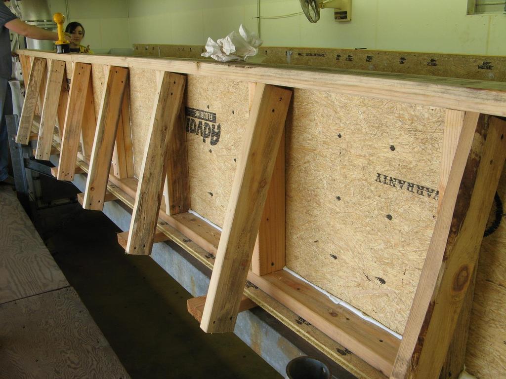
18 Flume Design Aspects Manometer / Orifice Plates

19 Flume Design Aspects Concrete Basin and Framing
20 Final Platform Design 10 Foot Wide 2 Foot High 10 Foot Long
21 Final Flume Design 3 Foot Wide 2 Foot High 16 Foot Long
22 Final Rock Box Design 3 Foot Wide 4 Foot High 8 Foot Long

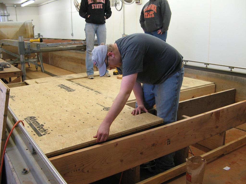
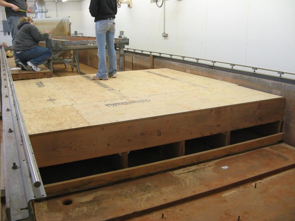
23 Platform Construction

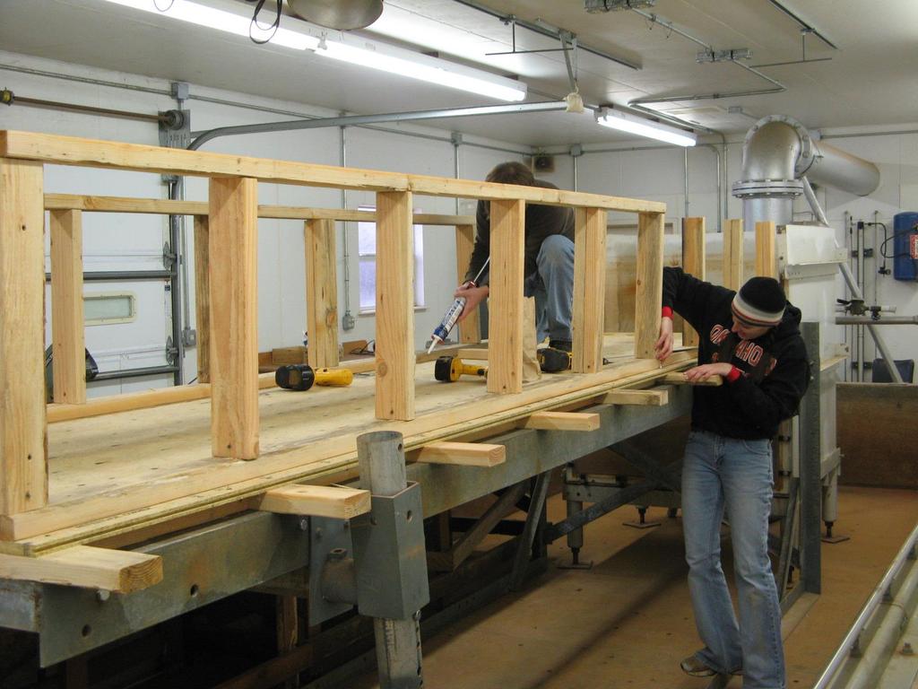

24 Flume Construction

25 Rockbox Construction
26 Proposed Cost Materials Qty $ ea. Total 4' x 8' x 3/4" 11 $21.44 $ " x 4" x 10' 21 $2.85 $ " x 6" x 8' 6 $3.84 $23.04 Plexiglass 1 $ $ Wood Screws (1 lb Box) 2 $6.97 $13.94 Wood Sealer (1 Gallon) 1 $20.00 $20.00 Silicon Caulking 5 $3.00 $15.00 Paint Roller Kit 1 $13.00 $13.00 Grand Total $554.38
27 Actual Cost Materials Qty $ ea. Total 2 x 12 x $10.42 $ x 4 x $2.96 $ x 8 x 3/4 11 $23.45 $ " Wood Screws (1 lb) 6 $3.86 $ " Wood Screws (1 lb) 4 $3.86 $15.44 Silicon Caulking 19 $2.69 $51.11 Wood Sealer (1 gal) 1 $12.88 $12.88 Miscellaneous $47.55 Grand Total $666.45
28 List of Common Terms Critical Depth ( d c ) - Depth of water flowing directly above weir Drop Height ( h ) Height from top of rip rap surface to top of weir Flow Rate ( Q ) Rate of fluid flow Head ( H ) Total height of water from ground level Length to Impact ( L ) Distance from floodwall to impact point Rip Rap Nominal Diameter ( D 50 ) Average diameter of a set of rip rap


29 Establish level railing Calibration Point Gauge Carriage was in place


30 Calibration Point Gauge readings were taken 5 ft upstream from the flood fall in order to read the head Manometer readings taken at each flow.
31 Calibration Floodwall Calibration Discharge (cfs) q (cfs/ft) Q (cfs) Q = 10.26x 1.5 R 2 = q = 3.42x 1.5 R 2 = H^1.5 (ft)

32 Experimental Setup Rock Size Selection D 50 = 0.05 ft D 50 = 0.11 ft D 50 = 0.17 ft D 50 = 0.29 ft
33 Experimental Setup Plexi Glass Wall Rip-Rap Drop Height Geofabric 2 x 4 s Sand


34 Bed Preparation Sand wetted well packed and level Geo-fabric between rock and sand Rock level


35 Test Procedure 1. Initiate discharge at a level that does not disrupt the riprap and record discharge by reading the point gage at station 49.

36 Test Procedure 2. Run at set flow for 15 minutes and make notes indicating observations of riprap movement.
37 Example Data Collection Sheet Test # 3 Drop height, ft 2 Recorder Jason rock size, mm 33 Date 4/5/2008 pt gage crest rd, ft x= 49 y= centerz= calibration curve: Q = CH 3/2 C = run # time sta. 49 head on flume pt gage crest discharge start/end rd, ft H, ft Q, cfs comments: stable/shift/scour 1 10: stable / no movement 10: : : : : : : : : visible rock swaying / stable overall / no movement minor movement initially / settled quickly / movement downstream and upstream of jet / scour bed 1 D50 deep displacement of 1 D50 depth at jet / visible failure at 11:40 / complete failure at 11:43


38 Test Procedure 3. Increase flow of water in increments proportional to the nominal dc. Repeat step 2 for each flow increase until geofabric is exposed.

39 Test Procedure 4. Once geofabric is exposed, turn off flow, and record scour.

40 Test Procedure 5. Repeat steps 1-3 of test set-up and 1-4 of test procedure until all rock sizes have been tested for the desired drop height. 6. Repeat the entire procedure for next drop height. 7. Conduct steps 1-6 on the third drop height (1 ) for verification data.


41 Test Results Drop Height = 2 ft. Failure D50 = 0.29 ft Failure D2.63 ft 50 = 0.17 Flow = cfs Failure D50 = 0.11 ft Flow = ftcfs dc = Flow = 0.65 cfs dc = 0.19 ft dc = 0.11 ft Failure D50 = 0.05 ft Flow = 0.18 cfs dc = 0.05 ft


42 Test Results Drop Height = 0.5 ft. No Failure D50 = 0.29ft Flow = 4.51 cfs dc = 0.41 ft No Failure D50 = 0.17 ft Flow = 3.77 cfs Failure D= = 0.05 ft Failure D ft 50 dc = 0.37 ft Flow = 0.31 cfs Flow = 2.10 cfs = 0.07 dcdc = 0.25 ft ft


43 Test Results Drop Height = 1 ft Failure of0.11 D ft Failure of D ft Failure of D 0.05 ft No Failure D50 = 0.29 ft Flow 2.24 cfs Flow =cfs 3.86 Flow 0.65 cfs cfs Flow 0.16 dcd= ft ft ft dcd0.045 c ft c 0.11
44 Test Results Performance Curve dc (ft) STABLE MINOR MAJOR FAILURE D 50 (ft)
45 Test Results Performance Chart D50 / dc h / dc Stable Minor Movement Major Movement Failure
46 Test Results Performance Chart Acceptable Design D50 / dc Design Failure h / dc Stable Minor Movement Major Movement Failure
47 Test Results Water Surface Profile 2.5 Water Surface Elevation (ft) FLOODWALL Q = 0.34 cfs Q = 2.63 cfs Station X (ft)
48 Test Results Impact Location L / dc y = x R 2 = h / dc
49 Example Problem 10 foot floodwall No current downstream protection 25 year storm event produces a dc = 1 ft. Find D 50 from Performance Chart D 50 = 1.3 ft. Find jet impact location from Impact Location Chart L = 5.7 ft. D50 / dc L / dc Performance Chart h / dc Impact Location Stable Minor Movement Major Movement Failure y = 2.36x 0.38 R 2 = h / dc
50 Conclusion Further Work Necessary Further testing of additional ranges on model flume Larger scale outdoor tests for verification Investigation of tailwater conditions Investigation of various downstream conditions Sloped embankments, etc.
51 Timeline 1/7 Design of Final Flume Model 1/22 Construction of Flume 3/24 Discussion of Equipment 3/31 Setup for Experimentation 4/7 Began Report 4/24 Final Presentation 5/2 Final Report Due 2/1 3/1 4/1 5/1 3/26 Calibration of Flume 4/2 Began Experimentation 4/13 Analyzation of Results 4/14 Began Presentation
52 The Dam & Levee Professionals Special Thanks to: Acknowledgements Dr. Weckler for his guidance throughout the last year Greg Hanson, Sherry Hunt, Bobby Sappington and Kem Kadavy for sharing their knowledge with us at the HERU laboratory And Dr. Fox for all his additional help in critical depth calculations

53 Questions?
HYDRAULIC JUMP AND WEIR FLOW
 HYDRAULIC JUMP AND WEIR FLOW 1 Condition for formation of hydraulic jump When depth of flow is forced to change from a supercritical depth to a subcritical depth Or Froude number decreases from greater
STRUCTURAL STABILITY ASSESSMENT
 STRUCTURAL STABILITY ASSESSMENT CFR 257.73(d) Fly Ash Reservoir II Cardinal Plant Brilliant, Ohio October, 2016 Prepared for: Cardinal Operating Company Cardinal Plant Brilliant, Ohio Prepared by: Geotechnical
APPENDIX C VEGETATED EMERGENCY SPILLWAY. VERSION 1.0 March 1, 2011
 APPENDIX C VEGETATED EMERGENCY SPILLWAY VERSION 1.0 March 1, 2011 [NOTE: Could use a better photo more clearly showing the emergency spillway in the context of the dam.] SECTION C-1: DESCRIPTION OF PRACTICE
Huntington District. For More Information Contact (304)
") Zoar Levee & Diversion Dam are located in the Muskingum River Basin highlighted in green to left. The Muskingum River Basin is the site of Ohio s first multiple purpose water management and land conservation
Zoar Levee & Diversion Dam are located in the Muskingum River Basin highlighted in green to left. The Muskingum River Basin is the site of Ohio s first multiple purpose water management and land conservation
Sediment Basin 7E-12. Design Manual Chapter 7 - Erosion and Sediment Control 7E - Design Information for ESC Measures BENEFITS.
 7E-12 Design Manual Chapter 7 - Erosion and Sediment Control 7E - Design Information for ESC Measures Sediment Basin BENEFITS Flow Control Erosion Control Sediment Control Runoff Reduction Flow Diversion
APPENDIX A STRUCTURE DESCRIPTIONS AND RATING CURVES
 3 4 5 6 7 8 9 0 3 APPENDIX A STRUCTURE DESCRIPTIONS AND RATING CURVES Kissimmee River Vol December 005 Version Draft 4 3 4 5 6 7 8 9 0 3 4 5 6 7 8 9 0 3 4 5 6 7 8 9 30 3 3 33 34 35 36 37 38 39 40 4 4 43
Experiment (13): Flow channel
: Flow channel") Experiment (13): Flow channel Introduction: An open channel is a duct in which the liquid flows with a free surface exposed to atmospheric pressure. Along the length of the duct, the pressure at the surface
Experiment (13): Flow channel Introduction: An open channel is a duct in which the liquid flows with a free surface exposed to atmospheric pressure. Along the length of the duct, the pressure at the surface
USING A LABYRINTH WEIR TO INCREASE HYDRAULIC CAPACITY. Dustin Mortensen, P.E. 1 Jake Eckersley, P.E. 1
 USING A LABYRINTH WEIR TO INCREASE HYDRAULIC CAPACITY Dustin Mortensen, P.E. 1 Jake Eckersley, P.E. 1 Plum Creek Floodwater Retarding Structure No. 6 is located in an area of Kyle, Texas, that is currently
Northern Indiana Public Service Company Michigan City Generating Station Primary Settling Pond Number Annual RCRA CCR Unit Inspection Report
 REPORT Northern Indiana Public Service Company Michigan City Generating Station Primary Settling Pond Number 2 2018 Annual RCRA CCR Unit Inspection Report Submitted to: Northern Indiana Public Service
Earthen Embankments. turning into larger, more costly repairs. The following. The State Dam Safety Program has inspection
 TOPIC: COMMON PROBLEMS FOR SMALL DAMS WITH CONCRETE CHANNEL SPILLWAYS The State Dam Safety Program has inspection requirements for state regulated dams. A dam, like any man-made structure, will change
STRUCTURE S-65 PURPOSE SPILLWAY OPERATION
 STRUCTURE S-65 This structure is a reinforced concrete, gated spillway with discharge controlled by three cable operated, vertical lift gates, and a reinforced concrete lock structure with two pairs of
DAIVÕES DAM SPILLWAY: A NOVEL SOLUTION FOR THE STILLING BASIN
 DAIVÕES DAM SPILLWAY: A NOVEL SOLUTION FOR THE STILLING BASIN Elsa Alves *, Felix Hernando and Rafael Chacón * Laboratório Nacional de Engenharia Civil (LNEC) Av. do Brasil, 101, 1700-066 Lisboa, Portugal
Low Gradient Velocity Control Short Term Steep Gradient Channel Lining Medium-Long Term Outlet Control Soil Treatment Permanent [1]
![Low Gradient Velocity Control Short Term Steep Gradient Channel Lining Medium-Long Term Outlet Control Soil Treatment Permanent [1]](/thumbs/80/80811988.jpg "Low Gradient Velocity Control Short Term Steep Gradient Channel Lining Medium-Long Term Outlet Control Soil Treatment Permanent [1]") Check Dams DRAINAGE CONTROL TECHNIQUE Low Gradient Velocity Control Short Term Steep Gradient Channel Lining Medium-Long Term Outlet Control Soil Treatment Permanent [1] [1] Though not generally considered
Check Dams DRAINAGE CONTROL TECHNIQUE Low Gradient Velocity Control Short Term Steep Gradient Channel Lining Medium-Long Term Outlet Control Soil Treatment Permanent [1] [1] Though not generally considered
Large-scale Field Test
 Vaskinn 1 Large-scale Field Test Kjetil Arne Vaskinn kav@trh.statkraftgroner.no Statkraft Grøner AS SUMMARY The objective the controlled failure of large-scale embankment is to monitor and record the failure
The Hydraulic Design of an Arced Labyrinth Weir at Isabella Dam
 Utah State University DigitalCommons@USU International Symposium on Hydraulic Structures Jun 28th, 1:30 PM The Hydraulic Design of an Arced Labyrinth Weir at Isabella Dam E. A. Thompson Sacramento District
Technical Report Culvert A Hydraulic Analysis
 DATE: November 3, 2011 Technical Report Culvert A Hydraulic Analysis TO: FROM: RE: Jim Reiser, P.E. Project Manager Parsons Brinckerhoff, Inc. Kurt Killian, P.E., CFM Parsons Brinckerhoff, Inc. Design
 Dam Modification Report Stingy Run Fly Ash Reservoir Appendix E Spillway System Design Calculations E1: Spillway/Energy Dissipater Design for 100-year Event CHE8273 8 September 4, 2014 Written by: CJW
IMPACT OF MAKING THE CREST OF WEIR MULTIFACETED ON DISCHARGE COEFFICIENT OF MORNING GLORY SPILLWAY
 IMPACT OF MAKING THE CREST OF WEIR MULTIFACETED ON DISCHARGE COEFFICIENT OF MORNING GLORY SPILLWAY Ali Bagheri 1 and *Ebrahim Nohani 2 1 Department of Water Engineering, Qaemshahr Branch, Islamic Azad
General Information for Culvert Design
 Design Manual Chapter 2 - Stormwater 2E - Culvert Design 2E-1 General Information for Culvert Design A. Introduction A culvert is a conduit under an embankment that transports stormwater from one side
Plan B Dam Breach Assessment
 Plan B Dam Breach Assessment Introduction In support of the Local Sponsor permit applications to the states of Minnesota and North Dakota, a dam breach analysis for the Plan B alignment of the Fargo-Moorhead
CLAIBORNE LOCK AND DAM PERTINENT DATA
 CLAIBORNE LOCK AND DAM PERTINENT DATA GENERAL Location Clarke, Monroe, & Wilcox Counties, Alabama; Alabama River, river mile 72.5 Drainage area Millers Ferry to Claiborne sq. mi. 836 Total drainage area
REVETMENTS. Purposes and Operational Constraints. Purposes Erosion control o o. Revetment Design 4/5/2016. CE A676 Coastal Engineering
 REVETMENTS Ijsseldam, the Netherlands Orson P. Smith, PE, Ph.D. Instructor Purposes and Operational Constraints Purposes Erosion control o o Embankment Toe protection for a seawall, retaining wall or other
Designing Labyrinth Spillways for Less than Ideal Conditions Real World Application of Laboratory Design Methods
 Designing Labyrinth Spillways for Less than Ideal Conditions Real World Application of Laboratory Design Methods Gregory Richards, P.E., CFM, Gannett Fleming, Inc. Blake Tullis, Ph.D., Utah Water Research
INFILTRATION PRACTICE MAINTENANCE INSPECTION FORM
 Facility Number: Date: Time: Subdivision Name: Watershed: Weather: Inspector(s): Date of Last Rainfall: Amount: Inches Streets: Mapbook Location: GPS Coordinates: Property Classification: Residential 9
Temporary Flood Protection Research at U of M. Title of presentation. Faculty of Engineering. Shawn Clark, Ph.D., P.Eng.
 Temporary Flood Protection Research at U of M Shawn Clark, Ph.D., P.Eng. Contributors: James Blatz, Steven Harms, Raymond Offman, Kevin Sagan Title of presentation umanitoba.ca Faculty of Engineering Photo
Annex E Bridge Pier Protection Plan
 Annex E Bridge Pier Protection Plan Table E1 Bridge Types and Locations Table E2 Flow Conditions For River Sections Figure E1 Bridge Abutment Protection Figure E2 Bridge Pier Protection Figure E3 Central
COST EFFECTIVE STORAGE CAPACITY INCREASE FOR ALUMINA TAILINGS DISPOSAL AREA THROUGH SPILLWAY OPTIMISATION
 COST EFFECTIVE STORAGE CAPACITY INCREASE FOR ALUMINA TAILINGS DISPOSAL AREA THROUGH SPILLWAY OPTIMISATION Abstract Lonie I * Tailings and Dams, GHD Brisbane, QLD, Australia Queensland Alumina Limited operates
Illinois State Water Survey
 Illinois State Water Survey HYDROLOGY DIVISION SWS Contract Report 508 COMPARISON OF 1987 AND 1989 BED PROFILE SURVEYS OF THE LOWER CACHE RIVER by Richard Allgire Office of Sediment and Wetland Studies
19.1 Problem: Maximum Discharge
 19.1 Problem: Maximum Discharge In partially full channel having an equilateral triangular cross section, the rate of discharge is Q = KAR/3 in which K is a constant, A flow area, R is the hydraulic mean
STRUCTURE 65-B PURPOSE SPILLWAY OPERATION
 STRUCTURE 65-B This structure is a reinforced concrete, gated spillway with discharge controlled by three cable operated vertical lift gates and a reinforced concrete lock structure with two pairs of sector
Inner Harbor Navigation Canal (IHNC) Basin 1% (100-yr) and 0.2% (500-yr) Surge and Wave Event Water Levels
 Basin 1% (100-yr) and 0.2% (500-yr) Surge and Wave Event Water Levels") Inner Harbor Navigation Canal (IHNC) Basin 1% (100-yr) and 0.2% (500-yr) Surge and Wave Event Water Levels Dr. John Grieshaber Hurricane Protection Office US Army Corps of Engineers Overview The IHNC basin
Inner Harbor Navigation Canal (IHNC) Basin 1% (100-yr) and 0.2% (500-yr) Surge and Wave Event Water Levels Dr. John Grieshaber Hurricane Protection Office US Army Corps of Engineers Overview The IHNC basin
Stability of Concrete Macro-Roughness Linings for Overflow Protection of Earth Embankment Dams ( 1 ) - Discussion
 - Discussion") Stability of Concrete Macro-Roughness Linings for Overflow Protection of Earth Embankment Dams ( 1 ) - Discussion H. Chanson (Reader) Dept of Civil Engineering, The University of Queensland, Brisbane QLD
Stability of Concrete Macro-Roughness Linings for Overflow Protection of Earth Embankment Dams ( 1 ) - Discussion H. Chanson (Reader) Dept of Civil Engineering, The University of Queensland, Brisbane QLD
UNDERWATER BRIDGE INSPECTION REPORT DISTRICT 1 PINE COUNTY
 UNDERWATER BRIDGE INSPECTION REPORT STRUCTURE NO. 58551 CSAH NO. 41 OVER THE KETTLE RIVER DISTRICT 1 PINE COUNTY JULY 28, 2012 PREPARED FOR THE MINNESOTA DEPARTMENT OF TRANSPORTATION BY COLLINS ENGINEERS,
CHAPTER 4 SPALDING COUNTY, GEORGIA 4.0 CULVERT DESIGN
 SPALDING COUNTY, GEORGIA CHAPTER 4 4.0 CULVERT DESIGN... 4-1 4.1 INTRODUCTION... 4-1 4.2 SYMBOLS AND DEFINITIONS... 4-1 4.3 ENGINEERING DESIGN CRITERIA... 4-2 4.3.1 FREQUENCY FLOOD... 4-2 4.3.2 VELOCITY
As temporary grade control facilities along waterways until final stabilization is established.
 Check Dams (CD) EC-12 Description Check dams are temporary grade control structures placed in drainage channels to limit the erosivity of stormwater by reducing flow velocity. Check dams are typically
Water budgets of the two Olentangy River experimental wetlands in 1998
 Water budgets of the two Olentangy River experimental wetlands in 1998 Naiming Wang and William J. Mitsch School of Natural Resources The Ohio State University Water Budgets 17 Introduction An understanding
MEMORANDUM. TNC Fisher Slough Final Design and Permitting Subject: DRAFT Technical Memorandum: Levee Emergency Spillway Design
 MEMORANUM TNC Fisher Slough Final esign and Permitting Subject: RAFT Technical Memorandum: Levee Emergency Spillway esign To: From: Internal Memorandum For Record Yen Hsu Chen (Tetra Tech) avid Cline (Tetra
Water budgets of the two Olentangy River experimental wetlands in 2001
 Water Budgets 23 Water budgets of the two Olentangy River experimental wetlands in 2001 Li Zhang and William J. Mitsch School of Natural Resources, The Ohio State University Introduction Hydrologic conditions
Broadly speaking, there are four different types of structures, each with its own particular function:
 3 The selection of structures 3.1 Introduction In selecting a suitable structure to measure or regulate the flow rate in open channels, all demands that will be made upon the structure should be listed.
Suitable Applications Check dams may be appropriate in the following situations: To promote sedimentation behind the dam.
 Categories EC Erosion Control SE Sediment Control TC Tracking Control WE Wind Erosion Control Non-Stormwater NS Management Control Waste Management and WM Materials Pollution Control Legend: Primary Category
Effect of Fluid Density and Temperature on Discharge Coefficient of Ogee Spillways Using Physical Models
 RESEARCH ARTICLE Effect of Fluid Density and Temperature on Discharge Coefficient of Ogee Spillways Using Physical Models M. SREENIVASULU REDDY 1 DR Y. RAMALINGA REDDY 2 Assistant Professor, School of
HY-8 Version 7.2 Build Date January 17, Federal Highway Administration.
 HY-8 Version 7.2 Build Date January 17, 2012 Federal Highway Administration http://www.fhwa.dot.gov/engineering/hydraulics/software/hy8/index.cfm SIMPLE Simple to use Use for simple culverts and bridges
Hours / 100 Marks Seat No.
 17421 21415 3 Hours / 100 Marks Seat No. Instructions : (1) All Questions are compulsory. (2) Answer each next main Question on a new page. (3) Illustrate your answers with neat sketches wherever necessary.
HISTORY OF CONSTRUCTION
 HISTORY OF CONSTRUCTION CFR 257.73(c)(1) West Boiler Slag Pond Clifty Creek Plant Madison, Indiana October, 2016 Prepared for: Indiana Kentucky Electric Corporation Prepared by: American Electric Power
Culvert Design for Low and High Gradient Streams in the Midwest. Dale Higgins, Hydrologist Chequamegon-Nicolet National Forest
 Culvert Design for Low and High Gradient Streams in the Midwest Dale Higgins, Hydrologist Chequamegon-Nicolet National Forest Overview Culvert Design Considerations Hydraulic Terms Culvert Impacts Low
Introduction to Check Dams
 Introduction to Check Dams Kabul, Afghanistan February 2011 3 This watershed rehabilitation and restoration training was prepared by the U.S. Department of Agriculture (USDA) team of Jon Fripp (Civil Engineer
SUBMERGED VENTURI FLUME. Tom Gill 1 Robert Einhellig 2 ABSTRACT
 SUBMERGED VENTURI FLUME Tom Gill 1 Robert Einhellig 2 ABSTRACT Improvement in canal operating efficiency begins with establishing the ability to measure flow at key points in the delivery system. The lack
UNDERWATER BRIDGE INSPECTION REPORT STRUCTURE NO B WABASHA STREET SOUTH BOUND (MASA 235 SB)
") UNDERWATER BRIDGE INSPECTION REPORT STRUCTURE NO. 62555B WABASHA STREET SOUTH BOUND (MASA 235 SB) OVER THE MISSISSIPPI RIVER CITY OF ST. PAUL OCTOBER 31, 2012 PREPARED FOR THE MINNESOTA DEPARTMENT OF TRANSPORTATION
UNDERWATER BRIDGE INSPECTION REPORT STRUCTURE NO. 62555B WABASHA STREET SOUTH BOUND (MASA 235 SB) OVER THE MISSISSIPPI RIVER CITY OF ST. PAUL OCTOBER 31, 2012 PREPARED FOR THE MINNESOTA DEPARTMENT OF TRANSPORTATION
Chapter 11. Culverts and Bridges Design Checklist for Culvert Design
 Yes No N/A Design Requirements I. GENERAL DESIGN GUIDELINES Chapter 11. Culverts and Bridges A. Culvert design is in accordance with the Culverts chapter of Volume 2 of the UDFCD Manual for additional
BEACH EROSION COUNTERMEASURE USING NEW ARTIFICIAL REEF BLOCKS
 BEACH EROSION COUNTERMEASURE USING NEW ARTIFICIAL REEF BLOCKS Kyuhan Kim 1, Sungwon Shin 1, Chongkun Pyun 2, Hyundong Kim 3, and Nobuhisa Kobayashi 4 Two-dimensional and three-dimensional laboratory experiments
Stormwater Level of Service Study - Phase 2 Flooding Adjacent to Rock Creek
 Stormwater Level of Service Study - Phase 2 Flooding Adjacent to Rock Creek City of Fairway, Kansas Fairway Stormwater Level of Service Study - Phase 2 Project No. 108200 Revision 1 12/6/2018 Stormwater
UNDERWATER BRIDGE INSPECTION REPORT STRUCTURE NO CSAH 133 OVER A DITCH ST. LOUIS COUNTY
 UNDERWATER BRIDGE INSPECTION REPORT STRUCTURE NO. 7780 CSAH 133 OVER A DITCH ST. LOUIS COUNTY SEPTEMBER 27, 2012 PREPARED FOR THE MINNESOTA DEPARTMENT OF TRANSPORTATION BY COLLINS ENGINEERS, INC. JOB NO.
Session C9: Priest Rapids Fish Bypass: A Case Study from Start to Finish
 University of Massachusetts - Amherst ScholarWorks@UMass Amherst International Conference on Engineering and Ecohydrology for Fish Passage International Conference on Engineering and Ecohydrology for Fish
Spillway Design for Small Dams
 Spillway Design for Small Dams by David E. Fantina, PE Introduction: This course presents an overview of the features that go into the design of spillways for small dams. Small dams in this course refer
Indiana LTAP Road Scholar Core Course #10 Culvert Drainage. Presented by Thomas T. Burke, Jr., PhD, PE Christopher B. Burke Engineering, Ltd.
 Indiana LTAP Road Scholar Core Course #10 Culvert Drainage Presented by Thomas T. Burke, Jr., PhD, PE Christopher B. Burke Engineering, Ltd. Objectives Review culvert shapes, end sections, and materials
INTERNATIONAL JOURNAL OF CIVIL AND STRUCTURAL ENGINEERING Volume 3, No 1, 2012
 INTERNATIONAL JOURNAL OF CIVIL AND STRUCTURAL ENGINEERING Volume 3, No 1, 2012 Copyright by the authors - Licensee IPA- Under Creative Commons license 3.0 Research article ISSN 0976 4399 ABSTRACT Scour
LEHIGH UN IVERS ITY CIVIL ENGINEERING DEPARTMENT. Project Report No. 54. Prepared by. John R. Adam~;.,:~."; Arthur W. Brune and Stephen C.
 LEHIGH UN IVERS ITY CIVIL ENGINEERING DEPARTMENT FRITZ ENGINEERING laboratory HYDRAULIC AND SANITARY ENGINEERING DIVISION SPILLWAY MODEL STUDY FOR TWO LICK CREEK DAM Project Report No. 54 Prepared by John
APPENDIX J HYDROLOGY AND WATER QUALITY
 APPENDIX J HYDROLOGY AND WATER QUALITY J-1 Technical Report on Airport Drainage, Northern Sector Airport and Ordinance Creek Watershed / Preliminary Creek Constructed Natural Channel Culvert J-2 Preliminary
Components of a Barrage
 Components of a Barrage Definition The only difference between a weir and a barrage is of gates, that is the flow in barrage is regulated by gates and that in weirs, by its crest height. Barrages are costlier
APPENDIX A STRUCTURE DESCRIPTIONS AND RATING CURVES. Lake Okeechobee & EAA Vol 3 A-i December 2005 Version 1 Draft 4
 1 1 1 1 1 1 1 1 0 1 0 1 0 APPENDIX A STRUCTURE DESCRIPTIONS AND RATING CURVES Lake Okeechobee & EAA Vol A-i December 00 1 1 1 1 1 1 1 1 0 1 from the drainage area served, under a design head of. feet pool
Transition Submergence and Hysteresis Effects in Three-Foot Cutthroat Flumes
 Transition Submergence and Hysteresis Effects in Three-Foot Cutthroat Flumes Why Measure Water for Irrigation? (You had to ask.) Improve: Accuracy Convenience Economics Water Measurement Manual (Door Prize)
Design of Spillway Upgrades
 USACE Dam Safety Program Design of Spillway Upgrades Sal Todaro, P.E. Senior Hydraulic Structures Engineer U.S. Army Corps of Engineers Risk Management Center 1 Presentation Overview 1. USACE (RMC) approach
OFFICE OF STRUCTURES MANUAL FOR HYDROLOGIC AND HYDRAULIC DESIGN CHAPTER 11 APPENDIX B TIDEROUT 2 USERS MANUAL
 OFFICE OF STRUCTURES MANUAL FOR HYDROLOGIC AND HYDRAULIC DESIGN CHAPTER 11 APPENDIX B TIDEROUT 2 USERS MANUAL APRIL 2011 APRIL 2011 Page 1 Preface TIDEROUT 2, Build 1.22 dated June 29, 2006 is the current
Rock Ramp Design Guidelines. David Mooney MS Chris Holmquist-Johnson MS Drew Baird Ph.D. P.E. Kent Collins P.E.
 Rock Ramp Design Guidelines David Mooney MS Chris Holmquist-Johnson MS Drew Baird Ph.D. P.E. Kent Collins P.E. Rock Ramp Design Guidelines OUTLINE Local and System Interactions with Rock Ramps Ramp Geometry
CLEANING, INSPECTION, AND TESTING OF SEWERS
 CLEANING, INSPECTION, AND TESTING OF SEWERS PART 1 - GENERAL 1.01 SECTION INCLUDES A. Cleaning, Inspecting, and Testing Sanitary Sewers B. Cleaning, Inspecting, and Testing Storm Sewers C. Cleaning and
Effects of Submergence in Montana Flumes
 Utah State University DigitalCommons@USU All Graduate Theses and Dissertations Graduate Studies 5-2010 Effects of Submergence in Montana Flumes Ryan P. Willeitner Utah State University Follow this and
PROFILE OF SACRAMENTO RIVER, FREEPORT TO VERONA, CALIFORNIA,
 PROFILE OF SACRAMENTO RIVER, FREEPORT TO VERONA, CALIFORNIA, FLOOD OF FEBRUARY 1986 By J.C. Blodgett and J.B. Lucas U.S. GEOLOGICAL SURVEY Open-File Report 88-82 CO CM I m r-h CM Sacramento, California
ANNUAL INSPECTION BY A QUALIFIED PROFESSIONAL ENGINEER ALL CCR IMPOUNDMENTS CCR Rule Section (b)
") ANNUAL INSPECTION BY A QUALIFIED PROFESSIONAL ENGINEER ALL CCR IMPOUNDMENTS ASBURY POWER PLANT 21133 Uphill Lane Asbury, Missouri 64832 January 18, 2017 EMPIRE DISTRICT ELECTRIC COMPANY Prepared by: Rachel
ANNUAL INSPECTION BY A QUALIFIED PROFESSIONAL ENGINEER ALL CCR IMPOUNDMENTS ASBURY POWER PLANT 21133 Uphill Lane Asbury, Missouri 64832 January 18, 2017 EMPIRE DISTRICT ELECTRIC COMPANY Prepared by: Rachel
Hard Hat Services ph: hardhatinc.com 932 N. Wright St., Suite 160 Naperville, IL 60563
 Interstate Power and Light Company Ottumwa Generation Station CCR Surface Impoundment Annual Inspection Report 154.018.012.003 Report issued: December 21, 2016 Hard Hat Services ph: 877-630-7428 hardhatinc.com
Storm Damage Floating Culverts & Other Inlet Issues
 Storm Damage Floating Culverts & Other Inlet Issues Mark Bailey, PE - Hydraulic Manager, INDOT Dale Sedler, PE - Sr. Hydraulic Engineer, INDOT Road School 2016 What causes a culvert to float? 1. Accumulation
International Journal of Scientific & Engineering Research, Volume 5, Issue 1, January ISSN
 International Journal of Scientific & Engineering Research, Volume 5, Issue 1, January-2014 1356 Study of Safe Hydraulic Design of Stepped Spillway by Physical Models prof. Dr. Abdul-Hassan K. Al-Shukur,
where ρ f is the density of the fluid, V is the submerged volume of the object, and g is the acceleration due to gravity.
 July 23 Buoyant Force 1 Activity P13: Buoyant Force (Force Sensor) Concept DataStudio ScienceWorkshop (Mac) ScienceWorkshop (Win) Archimedes Principle P13 Buoyant Force.DS P18 Buoyant Force P18_BUOY.SWS
HEC 26 Aquatic Organism Passage Design Manual Evolution & Application
 HEC 26 Aquatic Organism Passage Design Manual Evolution & Application Sven Leon, P.E., Hydraulics Engineer Federal Highway Administration 2015 Alaska Fish Passage Meeting October 13 14, 2015 VTRC, Juneau,
OTC MS. Free Span Rectification by Pipeline Lowering (PL) Method N. I. Thusyanthan, K. Sivanesan & G. Murphy
 Method N. I. Thusyanthan, K. Sivanesan & G. Murphy") OTC-24699-MS Free Span Rectification by Pipeline Lowering (PL) Method N. I. Thusyanthan, K. Sivanesan & G. Murphy Copyright 2014, Offshore Technology Conference This paper was prepared for presentation
OTC-24699-MS Free Span Rectification by Pipeline Lowering (PL) Method N. I. Thusyanthan, K. Sivanesan & G. Murphy Copyright 2014, Offshore Technology Conference This paper was prepared for presentation
MODEL STUDY OF PRADO FLOOD-CONTROL DAM
 0 S -C Property of the United StatN Government. HL- - 19.. 2. TECHNICAL REPORT HL-89-19 MODEL STUDY OF PRADO FLOOD-CONTROL DAM Hydraulic Model Investigation by John F. George Hydraulics Laboratory DEPARTMENT
LABORATORY EXPERIMENTS ON WAVE OVERTOPPING OVER SMOOTH AND STEPPED GENTLE SLOPE SEAWALLS
 Asian and Pacific Coasts 23 LABORATORY EXPERIMENTS ON WAVE OVERTOPPING OVER SMOOTH AND STEPPED GENTLE SLOPE SEAWALLS Takayuki Suzuki 1, Masashi Tanaka 2 and Akio Okayasu 3 Wave overtopping on gentle slope
ANNUAL INSPECTION BY A QUALIFIED PROFESSIONAL ENGINEER ALL CCR IMPOUNDMENTS CCR Rule Section (b)
") ANNUAL INSPECTION BY A QUALIFIED PROFESSIONAL ENGINEER ALL CCR IMPOUNDMENTS ASBURY POWER PLANT 21133 Uphill Lane Asbury, Missouri 64832 January 18, 2019 LIBERTY UTILITIES Empire District Prepared by: Rachel
ANNUAL INSPECTION BY A QUALIFIED PROFESSIONAL ENGINEER ALL CCR IMPOUNDMENTS ASBURY POWER PLANT 21133 Uphill Lane Asbury, Missouri 64832 January 18, 2019 LIBERTY UTILITIES Empire District Prepared by: Rachel
Hydraulic Evaluation of the Flow over Polyhedral Morning Glory Spillways
 World Applied Sciences Journal 9 (7): 712-717, 2010 ISSN 1818-4952 IDOSI Publications, 2010 Hydraulic Evaluation of the Flow over Polyhedral Morning Glory Spillways 1 2 2 A. Bagheri, M. Shafai Bajestan,
JAP Additional Information Sheet
 JAP Additional Information Sheet Block 15: Purpose and Need The USACE purpose of the project is to provide a safe and reliable whitewater park for the recreational public in a city park, which will provide
UNDERWATER BRIDGE INSPECTION REPORT DISTRICT 8 - LAC QUI PARLE COUNTY
 UNDERWATER BRIDGE INSPECTION REPORT STRUCTURE NO. 6391 CSAH NO. 33 OVER THE MINNESOTA RIVER DISTRICT 8 - LAC QUI PARLE COUNTY OCTOBER 22, 2012 PREPARED FOR THE MINNESOTA DEPARTMENT OF TRANSPORTATION BY
Total Suspended Solids, Stable Flow, and Wet Weather Event Monitoring in the Unnamed Tributary to the Grand River Watershed.
 Total Suspended Solids, Stable Flow, and Wet Weather Event Monitoring in the Unnamed Tributary to the Grand River Watershed December 2004 The Cadmus Group, Inc. Grand Valley State University Annis Water
Hours / 100 Marks Seat No.
 17421 15116 3 Hours / 100 Seat No. Instructions (1) All Questions are Compulsory. (2) Answer each next main Question on a new page. (3) Illustrate your answers with neat sketches wherever necessary. (4)
Greenup Lock Filling and Emptying System Study
 Fourth LACCEI International Latin American and Caribbean Conference for Engineering and Technology (LACCET 2006) Breaking Frontiers and Barriers in Engineering: Education, Research and Practice 21-23 June
Scott Dam Spillway Comparing Physical Model Study Results
 Scott Dam Spillway Comparing Physical Model Study Results Darren Hinton, P.E., Ph.D., Seattle Laboratory Manager, Northwest Hydraulic Consultants, USA Brian Hughes, M.A.Sc., P.E., Principal, Northwest
Hard Hat Services ph: hardhatinc.com 932 N. Wright St., Suite 160 Naperville, IL 60563
 Interstate Power and Light Company Ottumwa Generation Station CCR Surface Impoundment Annual Inspection Report 154.018.015.003 Report issued: July 03, 2017 Hard Hat Services ph: 877-630-7428 hardhatinc.com
Packwood Hydroelectric Project Barrier Analysis December 12, 2006
 Packwood Hydroelectric Project Barrier Analysis December 12, 2006 Study Area Natural barriers to upstream fish passage on Lake Creek at RM 1.03 and RM 1.95 Snyder Creek culvert under the Project tailrace
Chadbourne Dam Repair and Fish Barrier
 Chadbourne Dam Repair and Fish Barrier Final Report for the Western Native Trout Initiative Prepared by: Carol Endicott Yellowstone Cutthroat Trout Conservation Biologist Montana Fish, Wildlife & Parks
CSO/STORMWATER MANAGEMENT. HYDROVEX VHV / SVHV Vertical Vortex Flow Regulator
 CSO/STORMWATER MANAGEMENT HYDROVEX VHV / SVHV Vertical Vortex Flow Regulator HYDROVEX VHV / SVHV VERTICAL VORTEX FLOW REGULATOR APPLICATIONS One of the major problems of urban wet weather flow management
UNDERWATER BRIDGE INSPECTION REPORT DISTRICT 8 - LAC QUI PARLE COUNTY
 UNDERWATER BRIDGE INSPECTION REPORT STRUCTURE NO. 6391 CSAH NO. 33 OVER THE MINNESOTA RIVER DISTRICT 8 - LAC QUI PARLE COUNTY PREPARED FOR THE MINNESOTA DEPARTMENT OF TRANSPORTATION BY COLLINS ENGINEERS,
CHAPTER 5 CULVERT DESIGN
 CHAPTER 5 CULVERT DESIGN HYDRAULICS OF CULVERTS There are two major types of culvert flow: 1) flow with inlet control, and 2) flow with outlet control. For each type, different factors and formulas are
Chutes Part 2: Synthetic linings
 s Part 2: Synthetic linings DRAINAGE CONTROL TECHNIQUE Low Gradient Velocity Control Short Term Steep Gradient Channel Lining Medium-Long Term Outlet Control [1] Soil Treatment Permanent [2] [1] s can
Culvert Design An Overview of the NYS Highway Design Manual Chapter 8
 Seventeenth Statewide Conference on Local Bridges Culvert Design An Overview of the NYS Highway Design Manual Chapter 8 Tuesday, October 25, 2011 Training Session: Culvert Design, Analysis - talk 2 Presented
Request Number IR1-12: Flow Passage. Information Request
 Request Number IR1-12: Flow Passage Information Request Provide additional information about the 100 metre flow passage channel scenario between the Westshore Terminals and the proposed Project terminal
The Basics of Culvert and Inlet Design
 PDHonline Course C619 (8 PDH) The Basics of Culvert and Inlet Design Jerry D. Morrow, PE 2013 PDH Online PDH Center 5272 Meadow Estates Drive Fairfax, VA 22030 6658 Phone & Fax: 703 988 0088 www.pdhonline.org
WMS 8.4 Tutorial Hydraulics and Floodplain Modeling HY-8 Modeling Wizard Learn how to model a culvert using HY-8 and WMS
 v. 8.4 WMS 8.4 Tutorial Hydraulics and Floodplain Modeling HY-8 Modeling Wizard Learn how to model a culvert using HY-8 and WMS Objectives Define a conceptual schematic of the roadway, invert, and downstream
APPENDIX C ESTIMATING SCOUR IN BOTTOMLESS ARCH CULVERTS
 OFFICE OF STRUCTURES MANUAL FOR HYDROLOGIC AND HYDRAULIC DESIGN CHAPTER 11, EVALUATING SCOUR AT BRIDGES APPENDIX C ESTIMATING SCOUR IN BOTTOMLESS ARCH CULVERTS APRIL 2011 APPENDIX C ESTIMATING SCOUR IN
UNDERWATER BRIDGE INSPECTION REPORT METRO DISTRICT - ANOKA COUNTY
 UNDERWATER BRIDGE INSPECTION REPORT STRUCTURE NO. 02545 CR NO. 116 OVER THE RUM RIVER METRO DISTRICT - ANOKA COUNTY SEPTEMBER 9, 2012 PREPARED FOR THE MINNESOTA DEPARTMENT OF TRANSPORTATION BY COLLINS
Lessons Learned from Shoreline Protection Demonstration Projects in Southwest Louisiana
 Lessons Learned from Shoreline Protection Demonstration Projects in Southwest Louisiana Tommy McGinnis and Maggie Luent CPRA Operations Division Lafayette Regional Office State of the Coast June 01, 2018
UNDERWATER BRIDGE INSPECTION REPORT STRUCTURE NO MSAS 123 (2 ND AVE. SW) OVER THE CANNON RIVER CITY OF FARIBAULT, RICE COUNTY
 OVER THE CANNON RIVER CITY OF FARIBAULT, RICE COUNTY") UNDERWATER BRIDGE INSPECTION REPORT STRUCTURE NO. 66546 MSAS 123 (2 ND AVE. SW) OVER THE CANNON RIVER CITY OF FARIBAULT, RICE COUNTY SEPTEMBER 13, 2012 PREPARED FOR THE MINNESOTA DEPARTMENT OF TRANSPORTATION
UNDERWATER BRIDGE INSPECTION REPORT STRUCTURE NO. 66546 MSAS 123 (2 ND AVE. SW) OVER THE CANNON RIVER CITY OF FARIBAULT, RICE COUNTY SEPTEMBER 13, 2012 PREPARED FOR THE MINNESOTA DEPARTMENT OF TRANSPORTATION
Evaluating Surge Potential in CSO Tunnels
 14 Evaluating Surge Potential in CSO Tunnels Karen E. Ridgway Tunnels are being proposed to control combined sewer overflow (CSO) in numerous cities in the United States and Canada. The tunnels are intended