Master Meter Maintenance Manual
|
|
|
- Janel Harper
- 5 years ago
- Views:
Transcription
 1621 773292 Fax + 44 (0) 1621 772353 E-Mail sales@easternsupplies.co.")
1 Eastern Petroleum Supplies Ltd, New House Farm, Maldon Road, Steeple, Essex, CM0 7RR, UK Master Meter Maintenance Manual Tel + 44 (0) Fax + 44 (0) sales@easternsupplies.co.uk
2 Page2
3 Page3 Contents 1 Introduction Warranty Introduction Description 3 2 Installation Principles of operation Precautions Installation Aircraft Refueller Dispenser and Hydrant Systems Gantry, Pipeline and Bunkering Meters Road Delivery Tankers Preset Meters 6 3 Test procedure Calculation of Results Calculation with temperature compensation Calibration curve (example) 9 4 Maintenance Preservation after use Check Proving of Master Meter 10 Products maybe updated without condition of advanced notice. We do not undertake liability for use the dates that are modified
4 Page4
5 Page5 1 Introduction 1.1 Warranty Each device comes with a 1-year warranty, starting from the delivering date. Such warranty of good operating of the equipments includes our efforts of repairing or replacing, in the shortest time, the parts that fail for defective manufacturing or material during the warranty period, without rights to any refund for damages or other expenses. If a device is going to be transferred in our laboratory for repair, the delivery expenses is at the customer s expense. For any inspection of our qualified personnel related to what stated above, the labour is at our expenses, while the board, lodging and travel expenses are in charge at the customer. The components furnished and installed, but not produced, by us are covered by the guarantee released by the respective producers. The warranty ceases if non-original spare parts are used; the warranty ceases too for an improper use or if the operational limits of the device are exceeded. 1.2 Introduction 1. Still now a usual way of proving positive displacement meters is by means of proving tanks, specially designed and built tanks of known capacity. These methods, when carefully conducted by skilled operators, can be accurate, but they lay themselves open to many errors. They are also slow and the equipment is cumbersome. 2. The Master Meter system has been designed to simplify the whole procedure of checking the accuracy of a meter. In many applications this can be done with the meter under test in its normal operating position, and the equipment is easily transportable. Care is necessary in the use of a Master Meter, but provided the instructions in this manual are followed strictly, the whole operation is very quick and simple. 3. It cannot be emphasized too strongly that with modern meters, repeatability is such, that it should be possible to carry out a number of runs at the same speed and obtain consistent results. On occasion these may be varied by outside influences such as temperature, but the point of this note is to recommend that, if there is a variation in the results of repeated runs at the same speed, all conditions of test and method of operation should be examined very carefully before assuming that the fault lies in the meter under test. 4. No meter, including a Master Meter, is accurate, throughout its speed range, but provided it is consistent, and the variation is known, at any given speed of reading of the Master Meter may be corrected by the application of a factor. By using the electronic counter with the linearization of the error curve, the Master Meter error is very near to zero. For the purpose of this manual (+) plus indicates that the reading of the meter under test is greater than the reading of the master meter and (-) minus indicates that the reading of the meter under test is smaller than the reading of the master meter.
6 Page6 1.3 Description The Master Meter consists of a standard series P.D. Meter (mounted in a Carry Frame, mobile trolley, Road Going Trailer or Skid Base). The direction of flow through the meter is indicated by arrows on the meter manifold. It must be emphasized that the Master Meter, although robust, is a precision instrument and must be properly handled and treated to ensure that it maintains its accuracy. 2 Installation 2.1 Principles of operation There are four main principles to be observed: 1. Conditions of product, line pressure, rate of flow and temperature must be as near as possible the same as those prevailing in the normal service of the meter under test. 2. The same quantity of test product must pass through both meters. 3. Special care must be taken that neither air nor vapour passes through either meter. 4. As far as possible all conditions must be the same at the end of a proving run as they were at the beginning. In general, the performance of all meters varies, with changes in their operating conditions. Trials on these Master Meter have established its characteristics under various conditions of speed, product and pressure, and these are given in the form of factors with each Master Meter. Tests should be made in conditions as near as possible the same as those in which the meter under test is normally used, as the characteristics of other meters under varying condition may not be known. 2.2 Precautions The Master Meter must be drained of the product which was left in it for storage, before commencing any test. The most common source of error in metering and meter proving is the presence of air or vapour. This may be present in one or more of five forms: Air trapped in the meter or connecting pipe-work. Air drawn into the system through, for example, a leaking gland on a pump. Entrained air in the product. Formation of a vortex or cavitations in the product supply. Breaking of the product due to sudden drop of pressure caused by change of diameter in the pipe, or restriction of a valve for instance. Care must be taken to avoid high points in the pipe-work or hoses as these may easily trap air. Sharp bends are equally undesirable. The whole system must be very Thoroughly purged of air. This is best done by circulating the product. The control valve must be opened very slowly because, if air is present, there is a danger that the meters may race, with consequent damage. Circulating the product also has the advantage of stabilizing the temperature. If the return line is connected to the tank from which the pump is sucking, as would be probable in the case of a refueller, care must be taken to ensure that the discharge is drowned
7 Page7 otherwise the product will become aerated. It is essential to use a strainer between the pump and the upstream meter, the mesh of the strainer depending on the product. Because it is essential that the whole system shall remain full of product at all times, the flow must be controlled downstream of both meters. If this is not done, the velocity of the product will cause it to continue to flow through the meters after the control valve is shut. This will give false readings. The Master Meter is normally used with two flexible hoses. Even the stiffest flexible hose suffers from dilatation to some extent when pressurized. For this and other reasons it is essential that pressure and other conditions at the end of a proving run should be as nearly as possible the same as they were at the beginning. The flow should be available without fluctuations or pulsations 2.3 Installation Aircraft Refueller It is probable that no test rig will be required, the vehicle's own pump, strainer, air separator and hoses being sufficient. The refueller must contain sufficient product to ensure that there is no danger of the pump drain a vortex. Connect one of the vehicle's discharge hoses to the Master Meter input hose. Using another hose, connect the Master Meter discharge hose to the refueller fill point. If it is necessary to discharge over the top, take care that the end of the discharge hose is drowned. A control valve must be provided downstream of the Master Meter Dispenser and Hydrant Systems No pump other that that feeding the hydrant system is required, and the dispenser's strainer and air separator can be used. A large container is necessary in which to discharge the product used during proving and for this a refueller or bridging vehicle will probably be most convenient. Some hydrant schemes already incorporate a meter proving off-take close to the tank farm with a return line direct to the tanks. Connect the dispenser's discharge hose to the Master Meter input hose. Using another hose, connect the Master Meter discharge hose via the control valve to discharge container Gantry, Pipeline and Bunkering Meters When a Master Meter is used to test meters installed in conjunction with bulk vehicle overhead filling equipment (e.g. bulk vehicle filling gantries fitted with articulated loading arms) it should be connected via a suitable "T" piece at the base of the loading arm. It is essential that the system incorporating the meter under test and the Master Meter shall be maintained at the same operating pressure as the bulk vehicle filling line under normal operating conditions. In gantries for Bottom Loading(Fig.1), hose to Master Meter has to be connected to the API coupling at the end of the loading arm. Gantry meters are normally of the preset type, and this may entail fitting the check valve assembly downstream of the Master Meter

8 Page Road Delivery Tankers Much the same applies in this case. In those tankers which normally discharge by gravity, no air separator is necessary provided that the product is allowed to settle. Again, a container at a suitable level will be required. Care must be taken to avoid drawing a vortex in the tanker. ATTENTION: Standby Meters not installed and any meter which cannot be proved in its operating position Here a simple test rig is necessary. The first requirement is a supply of fuel under pressure. For this it may be possible to arrange an off-take from the normal service of an installation, or it may be necessary to provide a special pump for meter proving. This pump, preferably centrifugal, should have a capacity sufficient to prove the meter up to its maximum rated capacity provided that this is within the maximum rated capacity of the Master Meter, which must not be exceeded. If it is possible to use a pump on the existing installation it is probable that similar arrangements can be made for a strainer and an air separator, otherwise these two items should also be incorporated in the test rig. Control must be made for the discharge of the test product. If an existing pump is used, it is most important that the normal working of the installation shall have no effect on the Master Meter test rig. It is essential that there shall be two valve separation throughout between the test rig circuit and the normal installation pipe-work. 2.4 Preset Meters If the meter under test is fitted with a preset, it is advisable to test it in two stages: (1) If necessary adjust the preset mechanism to give a precise cut off so that the meter counter indicates exactly the preset quantity. The calibration of the meter under test should in no circumstances be adjusted during this operation. (2) Install the Master Meter with a valve downstream of it to control the flow. Preset a quantity larger than the test run and proceed as for a normal meter. Some presets incorporate a two stage shut-off valve, with a reduction of speed before the final closure. It is important that the preset quantity should be sufficient to ensure that the test run is Complete before the first stage shut-off comes into operation. Now check the calibration in accordance with a normal test procedure.
9 Page9 It is only possible to test the calibration of these meters by comparing the totalizer reading with the reading of the Master Meter. The throughput necessary to do this will depend upon the accuracy with which the totalizer can be read and upon the accuracy of the test Required, e.g. if the totalizer can only be read to within 1 litre and the result is required to be within 0-1 it will be necessary to run 1000 litres. The total throughput divided by the number of individual deliveries will give the quantity of each delivery. From this the accuracy of each delivery can be determined. The Master Meter is obviously not really suitable for testing repeating preset meters where the amount of each delivery is so small as to make the operation a lengthy and tedious process 3 Test procedure Drain the Master Meter, install it and throughly purge the whole system of air by circulating the product. It may be necessary to run several hundred liters for this purpose. Check carefully for leaks between the two meters. Now proceed as follows: 1- Stop the flow by shutting the control valve downstream of the meters but allow pumping to continue to maintain pressure. 2- Zeroize both meter counters. Check that there is no creep on the counters. 3- Open the control valve until the desired rate of flow is shown on the Master Meter rate of flow indicator or on the Digital Readout 4- Read and note pressure during each run. 5- Run EXACTLY 1000 litres as shown on the counter of the meter under test, leaving the pump running to maintain line pressure. Check that there is no creep on the counters. 6- Read the Master Meter counter, or if fitted, the units drum assembly to estimate to a smaller part of a unit.(or read on the Digital Readout) NOTES :- It is essential that the required rate of flow be reached as soon as possible and be maintained for as long as possible. Towards the end of the run, reduce the flow rate smoothly so as to get a precise shut-off. It is advisable to do runs in units of 100 as this makes the calculations of the results easier. The longer the run the more accurate will be resultant reading. 3.1 Calculation of Results Show two examples in which two meters are tested by two different Master Meters under different conditions of product. (a)correct Master Meter reading by the Master Meter error for the speed of the run. This gives the correct Master Meter reading. Speed of run 1000 l/min Master Meter A Master Meter B Master Meter error 1000 l/min % % A B Master Meter reading Correction Corrected Master Meter reading (b) The Meter error (E) as a percentage is calculated:
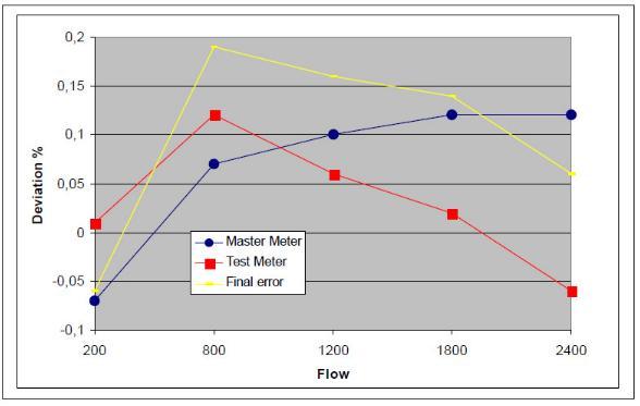
10 Page10 Vi - Vo E% = - x 100 Vo with: Vo = Master Meter reading Vi = Meter under test readin(c) The meter errors of our example are: A ,87 E (A) = x 100 = - 0,087% 1000,87 B ,42 E (A) = x 100 = - 0,087% 999, Calculation with temperature compensation Example: Master Meter Fluid : Diesel Speed of run : 1200litri/min Density at (15 C) : 850 Kg/m3 Master Meter error(error M/M %): 0,1% Meter under test: Reading(Vp): 10000litri Temperature: 18 C Correction of volume: to get coeff. from a ASTM table= Compensation reading at 15 C(Vp15): Vp * coeff. comp. = 10000litri * 0,9975=9975litri Master Meter Reading(Vo): 9998litri Temperature: 19 C Correction of volume: to get coeff. from a ASTM table= Compensation reading at 15 C(Vo15): Vp * coeff. comp. = 9998litri * 0,9967=9965litri Vp15 - Vo15 Error% = x 100 = = ( ) / (9965) *100 = 0,1% Vo15 Final error Test meter = Error % + Error M/M % = (0,1) + (0,1)% = 0,2
11 Page11
12 Page12 4 Maintenance 4.1 Preservation after use This section deals with matter special to the Master Meter. For routine maintenance and overhaul of the meter, The P.D. Meter manual should be consulted. The most important matter requiring attention is the thorough cleanliness of the meter, and the prevention of any corrosion. After use the meter should be emptied. To this prepare drip trays and then disconnect the hoses from the proving rig, first having drained the entire system as much as possible. Now open the valve on the drain line hose in a suitable container and pump out all the product. If the meter has been used on a black oil, it should be thoroughly washed out with Kerosene. Proceed as follows: With the meter inverted support both inlet and outlet hoses at as high a level as possible. Insert a funnel in the inlet hose and gradually pour in Kerosene until it appears in the outlet hose. Now pump the meter out as before. Continue until all the proving product has been removed. It is advisable that the meter capsule itself should be left full of clean kerosene when the Meter is not being used. This should be circulated by an hand pump once a month. To avoid contamination, care must be taken to drain this before starting a new test. 4.2 Check Proving of Master Meter Experience has shown that even after many millions of litres have been passed, the accuracy and calibration factors of these meters do not vary appreciably. Nevertheless, as the Master Meter may have suffered mechanical damage or neglect it is essential that it should be check tested from time to time. Where convenient this may be carried out in the proving rig at the manufacturer's works or whenever is possible
Compiled by: B Beard. Approved by: SH Carstens. Description of requirements and procedures for compact provers to be used as verification standards.
 1. Scope Description of requirements and procedures for compact provers to be used as verification standards. 2. Reference documents Trade Metrology Act SANS1698 3. Policy A. BASIC REQUIREMENTS Compact
MECHANICAL BULKMETERS BM Series
 PRO MEA 05 PRODUCTS - Measurement MECHANICAL BULKMETERS BM Series Positive displacement liquid measuring instruments Unequalled performance in measurement Free from installation effects Flow Rates of 25
Type , , S2.20 Specialized test procedure Procedure for testing LPG bulk meters using a vapour displacement prover
 Field Inspection Manual Part: 4-STP Section: 26 Page: 1 of 14 Type 52.11-13, 52.21-23, S2.20 Specialized test procedure Procedure for testing LPG bulk meters Application This test is applied to LPG bulk
Cover Page for Lab Report Group Portion. Pump Performance
 Cover Page for Lab Report Group Portion Pump Performance Prepared by Professor J. M. Cimbala, Penn State University Latest revision: 02 March 2012 Name 1: Name 2: Name 3: [Name 4: ] Date: Section number:
Summary of the MRA LPG Codes of Practice
 Summary of the MRA LPG Codes of Practice COP A1 DESIGN and INSTALLATION Code COP A1 deals with above ground installations where LPG is stored under pressure at ambient temperatures in fixed vessels larger
553 Series.
 38467.03 www.caleffi.com Pre-adjustable filling units Copyright 01 Caleffi 3 Series Function The automatic filling valve is a device consisting of a pressure reducing valve with compensating seat, visual
Air Eliminators and Combination Air Eliminators Strainers
 Description Air Eliminators and Combination Air Eliminator Strainers are designed to provide separation, elimination and prevention of air in piping systems for a variety of installations and conditions.
Water Weir Flow Controller. Introduction. Safety Precautions. Mounting the Hardware
 57007-88 Introduction Safety Precautions This instruction sheet describes how to set up and use the Hach (Figure 1). A water weir is a device that raises or diverts water to regulate the flow. Hach s water
Tentec. Instruction Document. Mini Air Driven Pump Unit Model: HTT.627X Series. Part Identifier
 Tentec Page 1 w w w. t e n t e c. n e t Instruction Document Mini Air Driven Pump Unit Model: HTT.627X Series HTT.6271 Maximum Working Pressure = 1500bar (21750 psi) HTT.6272 Maximum Working Pressure =
OWNER S TECHNICAL MANUAL
 EL SERIES OWNER S TECHNICAL MANUAL DP7002 1 Air Operated Diaphragm Pump Description The DP7002 1 air operated diaphragm pump is the ideal device for the pumping, transfer and dispensing of chemical liquids,
Chlorinator MODEL MK-I
 Chlorinator MODEL MK-I The New model MK- I is semi automatic gas type. Vacuum operated Solution feed Chlorinator designed to provide a continues & measured quantity of gas while in operation. It is suitable
Constant Pressure Inlet (CCN) Operator Manual
 Operator Manual") Constant Pressure Inlet (CCN) Operator Manual DOC-0125 Revision J 2545 Central Avenue Boulder, CO 80301-5727 USA C O P Y R I G H T 2 0 1 1 D R O P L E T M E A S U R E M E N T T E C H N O L O G I E S, I
Constant Pressure Inlet (CCN) Operator Manual DOC-0125 Revision J 2545 Central Avenue Boulder, CO 80301-5727 USA C O P Y R I G H T 2 0 1 1 D R O P L E T M E A S U R E M E N T T E C H N O L O G I E S, I
PRESSURISED PAINT CONTAINER
 PRESSURISED PAINT CONTAINER MODEL NO: CPP2B PART NO: 3082115 OPERATION & MAINTENANCE INSTRUCTIONS GC0913 INTRODUCTION Thank you for purchasing this CLARKE Pressurised Paint Container. Before attempting
DUPLEX PRESSURE REDUCING SET
 DUPLEX PRESSURE REDUCING SET Phoenix Pipeline Products Limited. Unit 8, McKenzie Industrial Park, Tel No.: 44 (0) 161 428 7200 Bird Hall Lane, Fax No.: 44 (0) 161 428 7010 Stockport, Email: info@p3-phoenix.com
I T T Pressure Reducing Valve WARNING INSTALLATION, OPERATION, AND MAINTENANCE MANUAL
 INSTALLATION, OPERATION, AND MAINTENANCE MANUAL I-867-4T 867-4T Pressure Reducing Valve HANG THESE INSTRUCTIONS ON THE INSTALLED VALVE FOR FUTURE REFERENCE WARNING Read and understand all instructions
5 Gallon Pressure Pot with HVLP Spray Gun and Hose
 California Air Tools 5 Gallon Pressure Pot with HVLP Spray Gun and Hose Model No. 365 Technical Data Type of feed.pressure Maximum pressure in the tank... 0,413Mpa (60PSI) Working pressure in the tank.0,
TITAN FLOW CONTROL, INC.
 PREFACE: This manual contains information concerning the installation, operation, and maintenance of Titan Flow Control (Titan FCI) Simplex Basket Strainers. To ensure efficient and safe operation of Titan
icon i150 / i350 Installation / Operation Manual
 i150 Concentrator i350 Concentrator icon i150 / i350 Installation / Operation Manual www.iconcentrator.com What You Will Need to Install Your icon In order to install your icon you will have to consider
OIL IN NAVIGABLE WATERS REGULATIONS [L.N. 101 of 1968.] under sections 5 and 7. [22nd April, 1968] [Comrnencernent.]
![OIL IN NAVIGABLE WATERS REGULATIONS [L.N. 101 of 1968.] under sections 5 and 7. [22nd April, 1968] [Comrnencernent.]](/thumbs/80/81393535.jpg "OIL IN NAVIGABLE WATERS REGULATIONS [L.N. 101 of 1968.] under sections 5 and 7. [22nd April, 1968] [Comrnencernent.]") OIL IN NAVIGABLE WATERS REGULATIONS [L.N. 101 of 1968.] under sections 5 and 7 [Comrnencernent.] [22nd April, 1968] 1. Short title and interpretation (1) These Regulations may be cited as the Oil in Navigable
OIL IN NAVIGABLE WATERS REGULATIONS [L.N. 101 of 1968.] under sections 5 and 7 [Comrnencernent.] [22nd April, 1968] 1. Short title and interpretation (1) These Regulations may be cited as the Oil in Navigable
WIKA INSTRUMENT CORPORATION
 WIKA INSTRUMENT CORPORATION Instruction Manual DIFFERENTIAL PRESSURE GAUGE Series 1500 Series 1000 Series 300 WIKA Instrument Corporation 1000 Wiegand Boulevard Lawrenceville, GA 30043 1-888-945-2872 http://www.wika.com
The Discussion of this exercise covers the following points:
 Exercise 5-3 Wet Reference Leg EXERCISE OBJECTIVE Learn to measure the level in a vessel using a wet reference leg. DISCUSSION OUTLINE The Discussion of this exercise covers the following points: Measuring
Vehicle-mounted meters, pump supplied
 Purpose This inspection procedure outline (IPO) defines the minimum tests which must be performed to ensure that basic volumetric measuring devices comply with the legislation. Application Vehicle-mounted
OIL SUPPLY SYSTEMS ABOVE 45kW OUTPUT 4.1 Oil Supply
 OIL SUPPLY SYSTEMS ABOVE 45kW OUTPUT 4.1 Oil Supply 4.1.1 General The primary function of a system for handling fuel oil is to transfer oil from the storage tank to the oil burner at specified conditions
Application and Sizing
 Application and Sizing Energy accumulator: It is improbable that an hydraulic system use all of its capacity without interruptions. An hydropneumatic accumulator can store a certain amount of fluid that
BACK PRESSURE / SUSTAINING
 In many liquid piping systems, it is vital that line pressure is maintained within relatively narrow limits. This is the function of the 108 Pressure Relief / Back Pressure Series of the OCV control valves.
Instructions for Use
 Select-380 T-Auto T-Auto Contents Page Instructions for Use Ref: 3.0 IFU 380 T-Auto Mar 18 2 Schematic layout of the doser 3 Quick-fit instructions 4 Description/Installation/Operation Pump tubes & Water
Validation of Custody Transfer Metering Skid at Site After Laboratory Proving
 flotek.g 2017- Innovative Solutions in Flow Measurement and Control - Oil, Water and Gas August 28-30, 2017, FCRI, Palakkad, Kerala, India Validation of Custody Transfer Metering Skid at Site After Laboratory
ANNEX AMENDMENTS TO THE INTERNATIONAL CODE FOR FIRE SAFETY SYSTEMS (FSS CODE) CHAPTER 15 INERT GAS SYSTEMS
 CHAPTER 15 INERT GAS SYSTEMS") Annex 3, page 2 ANNEX AMENDMENTS TO THE INTERNATIONAL CODE FOR FIRE SAFETY SYSTEMS (FSS CODE) CHAPTER 15 INERT GAS SYSTEMS The text of existing chapter 15 is replaced by the following: "1 Application This
Annex 3, page 2 ANNEX AMENDMENTS TO THE INTERNATIONAL CODE FOR FIRE SAFETY SYSTEMS (FSS CODE) CHAPTER 15 INERT GAS SYSTEMS The text of existing chapter 15 is replaced by the following: "1 Application This
LPG DRIVER ATTENDED TRANSPORT LOADING
 November 1993 Prepared By: Ken A. Steward. P.E. Linco-Electromatic, Inc. 4580 West Wall Street Midland, Texas 78703 LPG DRIVER ATTENDED TRANSPORT LOADING INTRODUCTION The safest and most accurate method
Accu-Tab Systems 2000 P Series by Axiall Corporation
 Accu-Tab Systems 2000 P Series by Axiall Corporation Installation and Operating Instructions Models 2075 P 2150 P For NSF/ANSI-Standard 61 NSF STANDARD 61 applications use NSF/ANSI Standard 60 listed Axiall
Cover Page for Lab Report Group Portion. Head Losses in Pipes
 Cover Page for Lab Report Group Portion Head Losses in Pipes Prepared by Professor J. M. Cimbala, Penn State University Latest revision: 02 February 2012 Name 1: Name 2: Name 3: [Name 4: ] Date: Section
High Pressure Inlet Kits for CONCOA BlendMites and BlendMasters
 ADI 3210-A ADI 3210-A Certified ISO 9001 Certified ISO 9001 High Pressure Inlet Kits for CONCOA BlendMites and BlendMasters Warning: An appropriately sized pressure relief device downstream of the regulator
CARTRIDGE FILTERS TECHNICAL MANUAL MT 080. Installation, commissioning and maintenance instructions. 08/02 Edition
 CARTRIDGE FILTERS TECHNICAL MANUAL MT 080 Installation, commissioning and maintenance instructions 08/02 Edition 1 2 CONTENTS 1.0 PAGE INTRODUCTION 1.1 MAIN FEATURES 1.2 OPERATION 1.3 CLOSING OF HEAD WITH
ONSITE PROVING OF GAS METERS. Daniel J. Rudroff WFMS Inc West Bellfort Sugar Land, Texas. Introduction
 ONSITE PROVING OF GAS METERS Daniel J. Rudroff WFMS Inc. 13901 West Bellfort Sugar Land, Texas Introduction With the increased use of Natural Gas as a fuel, and higher natural gas prices buyers and sellers
Coriolis Mass Flow Meter
 Coriolis Mass Flow Meter TMFW Series Mini Type Coriolis Mass Flow Meter Xi an Tosilon Automation Co., Ltd No.299, Daqing Rd, Lianhu District, Xi'an Shaanxi, China Tel: +86-29-8823 8550 info@tosilon.com;
Experiment Instructions. Circulating Pumps Training Panel
 Experiment Instructions Circulating Pumps Training Panel Experiment Instructions This manual must be kept by the unit. Before operating the unit: - Read this manual. - All participants must be instructed
Hill PHOENIX Second Nature Medium Temperature Secondary Refrigeration Start-Up Guide
 Hill PHOENIX Second Nature Medium Temperature Secondary Refrigeration Start-Up Guide Secondary Coolant System Start-Up Procedures June 2006 Produced by the Hill PHOENIX Learning Center DISCLAIMER This
OXY Integral. INTERCON ENTERPRISES INC Tel: Fax: Internet:
 OXY Integral INTERCON ENTERPRISES INC Tel: 800 665 6655 Fax: 604 946 5340 E-Mail: sales@intercononline.com Internet: www.intercononline.com Manual Integral 2006 1 INDEX 2-3 PREFACE 4 INTRODUCTION 5 Principle
Accu-Tab Systems 1000 Series by Axiall Corporation
 Accu-Tab Systems 1000 Series by Axiall Corporation Installation and Operating Instructions Model 1050 DANGER: DO NOT MIX CHEMICALS! The Accu-Tab chlorinator is designed for use with Axiall approved tablets
API MPMS Chapter 17.6 Guidelines for Determining the Fullness of Pipelines between Vessels and Shore Tanks
 API MPMS Chapter 17.6 Guidelines for Determining the Fullness of Pipelines between Vessels and Shore Tanks 1. Scope This document describes procedures for determining or confirming the fill condition of
OCTOBER 2017 ISSUE Page 1 of 7
 Field testing is performed on fully assembled pipelines for the purpose of determining pipeline acceptability. Following visual acceptance of joints and pipeline components, pressure pipelines in their
Radar, Ultrasonic and RF Level Transmitters
 Radar, Ultrasonic and RF Level Transmitters Both measures the time it takes the wave to travel between the transmitter and that reflected wave off the surface of the material to reach the transmitter again.
RESOLUTION A.567(14) adopted on 20 November 1985 REGULATION FOR INERT GAS SYSTEMS ON CHEMICAL TANKERS
 adopted on 20 November 1985 REGULATION FOR INERT GAS SYSTEMS ON CHEMICAL TANKERS") INTERNATIONAL MARITIME ORGANIZATION A 14/Res.567 16 January 1986 Original: ENGLISH ASSEMBLY - 14th session Agenda item lo(b) IMO RESOLUTION A.567(14) adopted on 20 November 1985 THE ASSEMBLY, RECALLING
INTERNATIONAL MARITIME ORGANIZATION A 14/Res.567 16 January 1986 Original: ENGLISH ASSEMBLY - 14th session Agenda item lo(b) IMO RESOLUTION A.567(14) adopted on 20 November 1985 THE ASSEMBLY, RECALLING
92831 TEL: (714) FAX:
 FAX:") Document N0. 1800-03 Copyright 2010 Terra Universal Inc. All rights reserved. Revised Sept. 2010 Terra Universal, Inc. TerraUniversal.com 800 S. Raymond Ave. Fullerton, CA 92831 TEL: (714) 578-6000 FAX:
Document N0. 1800-03 Copyright 2010 Terra Universal Inc. All rights reserved. Revised Sept. 2010 Terra Universal, Inc. TerraUniversal.com 800 S. Raymond Ave. Fullerton, CA 92831 TEL: (714) 578-6000 FAX:
MST21 Stainless Steel Balanced Pressure Thermostatic Steam Trap
 1250650/6 IM-P125-07 ST Issue 6 MST21 Stainless Steel Balanced Pressure Thermostatic Steam Trap Installation and Maintenance Instructions 1. Safety information 2. General product information 3. Installation
User Manual for the Mars Calibration Bench
 User Manual for the Mars Calibration Bench Fall 2013 Table of Contents Table of Contents Table of Contents... iii Introduction... v Chapter 1: The Mars Calibration Bench... 1 What Is the Mars Calibration
Acid- Rite ph Adjustment System 2500 by Axiall, a Westlake Company
 Acid- Rite ph Adjustment System 2500 by Axiall, a Westlake Company Installation and Operating Instructions DANGER: DO NOT MIX CHEMICALS! The Acid-Rite ph Adjustment System is designed for use with Axiall
Exercise 2-3. Flow Rate and Velocity EXERCISE OBJECTIVE C C C
 Exercise 2-3 EXERCISE OBJECTIVE C C C To describe the operation of a flow control valve; To establish the relationship between flow rate and velocity; To operate meter-in, meter-out, and bypass flow control
SLOP RECEPTION AND PROCESSING FACILITIES
 RULES FOR CLASSIFICATION OF SHIPS NEWBUILDINGS SPECIAL SERVICE AND TYPE ADDITIONAL CLASS PART 5 CHAPTER 8 SLOP RECEPTION AND PROCESSING FACILITIES JANUARY 2011 CONTENTS PAGE Sec. 1 General Requirements...
GILMONT ACCUCAL FLOWMETERS
 OPERATING MANUAL GILMONT ACCUCAL FLOWMETERS 28W092 Commercial Ave. Barrington, IL U.S.A. 60010-2392 (847) 381-4888 (847) 381-7053 (Fax) 800-962-7142 www.barnant.com e-mail: barnant@barnant.com A-1299-0766
PRAHER PLC-MP AQUASTAR MANAUL 2009
 PRAHER PLC-MP AQUASTAR MANAUL 2009 1. Copyrights This Operating Manual contains copyright-protected information. All rights reserved to Praher Kunststofftechnik GmbH. This Operating Manual is designed
RAM 4021 Operation Manual
 RAM 4021 Operation Manual Worldwide Manufacturer of Gas Detection Solutions TABLE OF CONTENTS RAM 4021 For your safety...3 Description...3 Set-up mode...4 Annunciator lights/alarms...4 Operation...5 Calibration...6
TOOL BOX 033- HOSEREEL SERVICE / FAULT FINDING
 In SANS 10105 you will find the Minimum water pressure for both the hydrant and the hose reel. Which is 300KPA Manufacturing Standard SANS 543 1 Front & Back plates 2 Curved Plate 3 Waterway assembly 4
BACK PRESSURE / SUSTAINING
 SPECIFICATIONS DIMENSIONS In many liquid piping systems, it is vital that line pressure is maintained within relatively narrow limits. This is the function of the 108 Pressure Relief / Back Pressure Series
ONSITE PROVING OF GAS TURBINE METERS Daniel J. Rudroff Invensys Metering Systems
 ONSITE PROVING OF GAS TURBINE METERS Daniel J. Rudroff Invensys Metering Systems 1322 Foxwood, Houston, Texas 77008 INTRODUCTION With the increased use of Natural Gas as a fuel, higher natural gas prices,
L 100. Bubble-Tube Level System. Installation, Operation and Maintenance Instructions
 L 100 Bubble-Tube Level System Installation, Operation and Maintenance Instructions Figure 1 Contents Section Description Page 1.0 Introduction 2 2.0 Specifications 3 3.0 Installation 3 4.0 Warranty 6
The Discussion of this exercise covers the following points:
 Exercise 3-2 Orifice Plates EXERCISE OBJECTIVE In this exercise, you will study how differential pressure flowmeters operate. You will describe the relationship between the flow rate and the pressure drop
TECHNICAL DATA. than the water inlet pressure to the concentrate
 Foam102a 1. DESCRIPTION The Viking Low Flow Foam/Water proportioning system, is a UL Listed and FM Approved system, for use with 3M foam concentrates. This system consists of a standard wet pipe sprinkler
OIL AND GAS INDUSTRY
 This case study discusses the sizing of a coalescer filter and demonstrates its fouling life cycle analysis using a Flownex model which implements two new pressure loss components: - A rated pressure loss
RAM Operation Manual. Worldwide Manufacturer of Gas Detection Solutions
 RAM 4021 Operation Manual Worldwide Manufacturer of Gas Detection Solutions TABLE OF CONTENTS RAM 4021 For Your Safety... 2 Description.... 2 Setup Mode.... 2 Lights/Alarms.... 3 Operation.... 4 Calibration....
Copyright, 2005 GPM Hydraulic Consulting, Inc.
 Troubleshooting and Preventive Maintenance of Hydraulic Systems Learning to Read the Signs of Future System Failures Instructed by: Al Smiley & Alan Dellinger Copyright, 2005 GPM Hydraulic Consulting,
Wedge Type Flow Meter Installation and Operation Manual
 Wedge Type Flow Meter Installation and Operation Manual 358-EN Please read and save these instructions. Wedge Type Flow Meter PLEASE READ THIS FIRST! The purpose of this document is to provide guidance
Tri-Safem Model I1 Regulator. INSTRUCTIONS and PARTS
 Tri-Safem Model I1 Regulator INSTRUCTIONS and PARTS USER RESPONSIBILITY This equipment will perform in conformity with the description thereof contained In this manual and accompanying labels andlor inserts
DC5A. Cyclone Separator Trap for Air. Copyright 2015 by TLV Co., Ltd. All rights reserved ISO 9001/ ISO MA-03 (DC5A) 19 June 2015
 19 June 2015") 172-65205MA-03 (DC5A) 19 June 2015 ISO 9001/ ISO 14001 Manufacturer Kakogawa, Japan is approved by LRQA LTD. to ISO 9001/14001 Cyclone Separator Trap for Air DC5A Copyright 2015 by TLV Co., Ltd. All rights
172-65205MA-03 (DC5A) 19 June 2015 ISO 9001/ ISO 14001 Manufacturer Kakogawa, Japan is approved by LRQA LTD. to ISO 9001/14001 Cyclone Separator Trap for Air DC5A Copyright 2015 by TLV Co., Ltd. All rights
Introduction to Pumps
 Introduction to Pumps 1 Introduction to Pumps 1.0 INTRODUCTION There are many different types of pump now available for use in pumped fluid systems. A knowledge of these pump types and their performance
Instructions for SILEX 1C Mixed bed cartridge filter
 D01B-30A-UK1 January 2017 Instructions for SILEX 1C Mixed bed cartridge filter With conductivity sensor Gravity flow or pressure installation SILHORKO-EUROWATER A/S Phone +45 86 57 12 22 DK-8660 Skanderborg
High Performance BSP Dial Up Pattern Pressure Reducing Valve
 See our full range online at: www.vip-ltd.co.uk High Performance BSP Dial Up Pattern Pressure Reducing Valve VIP Product Code 31/0103 FUNCTION Pressure reducing valves are devices which, when installed
Irrigation System Winterization and Pressurization Procedures
 Irrigation System Winterization and Pressurization Procedures Introduction Any time that an irrigation system is filled and pressurized, or when the system is drained and water flushed from the system,
Model 420-HY Pressure Regulating Hydrant Valve
 Model 420-HY Pressure Regulating Hydrant Valve INSTALLATION OPERATION MAINTENANCE 1. Safety First BERMAD believes that the safety of personnel working with and around our equipment is the most important
INSTALLATION OPERATION MAINTENANCE
 Bermad Electrically Controlled On-Off Deluge Valve Model: 400E-3D INSTALLATION OPERATION MAINTENANCE Application Engineering BERMAD 1. Safety First BERMAD believes that the safety of personnel working
Safety. April 2018 Supersedes all previous publications 2018 Chevron Phillips Chemical Company LP
 Technical Note 802 Leak Testing of Polyethylene Pipe For Municipal and Industrial Applications Part 1 Pre-Test Considerations Leak testing may be used to find leaks in a newly constructed or newly modified
DPC-30 DPC-100. Reference Manual
 DPC-30 DPC-100 Reference Manual 1. Introduction 1.1 Description The Martel DPC Digital Pneumatic Calibrator improves upon traditional dial gauge pneumatic calibrators. The Martel DPC improves accuracy,
MANUAL GAS MANIFOLDS
 MANUAL GAS MANIFOLDS Phoenix Pipeline Products Limited. Unit 8, McKenzie Industrial Park, Tel No.: 44 (0) 161 428 7200 Bird Hall Lane, Fax No.: 44 (0) 161 428 7010 Stockport, Email: info@p3-phoenix.com
BioAerosol Nebulizing Generator. Operation and Maintenance User Manual
 BioAerosol Nebulizing Generator Operation and Maintenance User Manual INTRODUCTION The BANG or BioAerosol Nebulizing Generator is a unique nebulizer for the generation of aqueous aerosols at a low air
INSTRUCTIONS FOR MODELS SG3897 AND SG3898 CROSS PURGE ASSEMBLIES
 INSTRUCTIONS FOR MODELS SG3897 AND SG3898 CROSS PURGE ASSEMBLIES THIS BOOKLET CONTAINS PROPRIETARY INFORMATION OF ADVANCED SPECIALTY GAS EQUIPMENT CORP. AND IS PROVIDED TO THE PURCHASER SOLELY FOR USE
User's Manual. MixRite TF 10. Edition 05.08
 User's Manual MixRite TF 10 Edition 05.08 1 Tefen MixRite TF 10 fertilizer and chemicals Injector Congratulations on your purchase of one of Tefen s high quality products. To get the best results from
Model: 720-UL INSTALLATION OPERATION MAINTENANCE. Bermad Pressure Reducing Valve IOM. Model: FP -720-UL Sizes: 2"-12" BERMAD. Application Engineering
 Bermad Pressure Reducing Valve Model: 720-UL INSTALLATION OPERATION MAINTENANCE Application Engineering BERMAD 1. Safety First BERMAD believes that the safety of personnel working with and around our equipment
80 Litre Suction Oil Drainer
 80 Litre Suction Oil Drainer Please dispose of packaging for the product in a responsible manner. It is suitable for recycling. Help to protect the environment, take the packaging to the local amenity
COSASCO 3600 PSI SINGLE ISOLATION SERVICE VALVE (FR) MAINTENANCE
 MAINTENANCE") COSASCO 3600 PSI SINGLE ISOLATION SERVICE VALVE (FR) MAINTENANCE Rohrback Cosasco Systems, Inc. 11841 E. Smith Avenue Santa Fe Springs, CA 90670 Tel: (562) 949-0123 (800) 635-6898 Fax: (562) 949-3065 www.cosasco.com
COSASCO 3600 PSI SINGLE ISOLATION SERVICE VALVE (FR) MAINTENANCE Rohrback Cosasco Systems, Inc. 11841 E. Smith Avenue Santa Fe Springs, CA 90670 Tel: (562) 949-0123 (800) 635-6898 Fax: (562) 949-3065 www.cosasco.com
DB 61 Dolphin TMV3 Integrated Thermostatic Mixing Valve
 INSTALLATION AND MAINTENANCE GUIDE DB 61 Dolphin TMV3 Integrated Thermostatic Mixing Valve Saving water, saving power, promoting hygiene Important: Read carefully before installing product DOLPHIN Revision
Pressure Regulator. Instructions for Use
 Pressure Regulator Instructions for Use 702-0083.9 December 2017 1. Symbols Warning! Caution! Indicates a potentially hazardous situation which, if not avoided, could result in injury to the patient, the
HYDROVEX TTT Membrane Flow Regulator
 HYDROVEX TTT Membrane Flow Regulator INSTALLATION, OPERATION AND MAINTENANCE MANUAL PROJECT EQUIPMENT LOCATION EQUIPMENT DESCRIPTION HYDROVEX TTT REFERENCE N OF THE SUPPLIER MODEL N SERIAL N DATE OF FABRICATION
Fisher DVI Desuperheater Venturi Inline
 Instruction Manual DVI Desuperheater Fisher DVI Desuperheater Venturi Inline Contents Introduction... 1 Scope of Manual... 1 Description... 1 Principle of Operation... 2 Installation... 3 Operating Instructions...
THE WAY THE VENTURI AND ORIFICES WORK
 Manual M000 rev0 03/00 THE WAY THE VENTURI AND ORIFICES WORK CHAPTER All industrial combustion systems are made up of 3 main parts: ) The mixer which mixes fuel gas with combustion air in the correct ratio
General Training Pty Ltd
 Introduction To The Purpose, Use and Care of Centrifugal Pumps Training For Operators, Maintainers, Technicians and Engineers. Objective This training teaches users and maintainers of centrifugal pumps
Automatic Non-freeze Valve NF6
 172-65134MA-03 (NF6) 30 March 2015 ISO 9001/ ISO 14001 Manufacturer Kakogawa, Japan is approved by LRQA LTD. to ISO 9001/14001 Automatic Non-freeze Valve NF6 Copyright 2015 by TLV CO., LTD. All rights
ENERGY BLADE 3K4. Energy Blade Installation Instructions
 ENERGY BLADE 3K4 Energy Blade Installation Instructions 1 Contents General information 2 Scope of these instructions 2 Product information 2 Designated use 3 Warranty 3 Safety instructions 4 Assembly and
OPERATING INSTRUCTIONS AND PARTS LIST HAND OPERATED LPG PISTON PUMP WITH SCALE 301-DH-SP
 OPERATING INSTRUCTIONS AND PARTS LIST HAND OPERATED LPG PISTON PUMP WITH SCALE 301-DH-SP www.adceng.co.za P O BOX 5413, JOHANNESBURG 2000 Phone: 011 493-8209 Fax: 011 493-1459 Email: adceng@mweb.co.za
DESIGN DATA A WET PIPE BLADDER TANK FOAM/WATER SYSTEM WITH HYDRAULICALLY ACTUATED DELUGE CONCENTRATE CONTROL VALVE
 February 9, 1998 Foam 101a A BLADDER TANK WITH 1. DESCRIPTION A Wet Pipe Bladder Tank Foam/Water System is a standard wet pipe automatic sprinkler system capable of discharging a foam/water solution automatically
HPIC D Hydrostatic Test Pump PRODUCT INFORMATION AND OPERATING INSTRUCTIONS
 WIDDER TOOLS HPIC-10000-D Hydrostatic Test Pump PRODUCT INFORMATION AND OPERATING INSTRUCTIONS Description: The WIDDER Hydrostatic Test Systems C Series is a portable, selfcontained, air driven hydrostatic
SCOPE OF THIS GUIDE STARTING-UP. 1 Check mini CORI-FLOW functional properties
 Quick Installation Guide Doc nr.: 9.17.052H Date: 10-12-2015 SCOPE OF THIS GUIDE mini CORI-FLOW instruments are highly accurate instruments for measuring and controlling the mass flow rate of liquids and/or
Module No. # 01 Lecture No. # 6.2 HAZOP (continued)
") Health, Safety and Environmental Management in Petroleum and Offshore Engineering Prof. Srinivasan Chandrasekaran Department of Ocean Engineering Indian Institute Of Technology, Madras Module No. # 01
Health, Safety and Environmental Management in Petroleum and Offshore Engineering Prof. Srinivasan Chandrasekaran Department of Ocean Engineering Indian Institute Of Technology, Madras Module No. # 01
Dialflow Regulator. Instructions for Use
 Dialflow Regulator Instructions for Use 702-0030.11 May 2014 1. Symbols Warning! Caution! Indicates a potentially hazardous situation which, if not avoided, could result in personal injury to the user
Oxygen Dialflow Meter. Instructions for Use
 Oxygen Dialflow Meter Instructions for Use 702-0031.9 May 2014 1. Symbols Warning! Caution! Indicates a potentially hazardous situation which, if not avoided, could result in personal injury to the user
TROUBLESHOOTING GUIDELINES
 TROUBLESHOOTING GUIDELINES PROBLEM: Performance 1. The most common problem in this area comes from inadequate flow to the LAKOS Separator(s). All LAKOS Separators operate within a prescribed flow range
TOP VALVE. Pat. #5,857,486 & 5,944,050. Mid-Range Pressure PSIG Back Pressure and Pressure Relief Valves. Instruction Manual
 TOP VALVE Pat. #5,857,486 & 5,944,050 Mid-Range Pressure 50 232 PSIG Back Pressure and Pressure Relief Valves Instruction Manual Please Note: This instruction manual provides detailed information and instructions
Pigging as a Flow Assurance Solution Avoiding Slug Catcher Overflow
 Pigging as a Flow Assurance Solution Avoiding Slug Catcher Overflow Aidan O'Donoghue, Pipeline Research Limited, Glasgow, UK This paper sets out to provide an initial method of assessing the bypass requirements
Bermad Pressure Reducing. Model: 42T
 Bermad Pressure Reducing Pilot Operated Pressure Control Valve Model: 42T Installation Operation Maintenance Manual (IOM) REV. 27.7.17 Page 1 of 12 Safety First BERMAD believes that the safety of personnel
TESCOM 50-4X Series Safety, Installation & Start-Up Procedures
 Operations & Service Manual TESCOM 50-4X Series Safety, Installation & Start-Up Procedures Do not attempt to select, install, use or maintain this product until you have read and fully understood this
my SYSTEM A guide to common applications in water distribution systems
 my SYSTEM A guide to common applications in water distribution systems WWW.SINGERVALVE.COM INDEX This short guide is intended to offer guidance on some of the common problems, applications and questions