SMALL SIZE. The Smart Chain Choice!
|
|
|
- Kerrie Bridges
- 5 years ago
- Views:
Transcription

1 SMLL SIZE COVEYOR CIS he Smart Chain Choice!

2 In Markets round the World. Only from SUBKI. SUBKI Small Size Conveyor Overseas Group Companies SUBKI Group Environmental olicy hilosophy he subaki Group understands that the preservation of the Earth s environment is one of the highest priorities for humankind. Our aim is to consider the environment in all of our activities to contribute to the creation of a healthy and wealthy tomorrow. Basic olicy We strive to understand the environmental aspect of our business activities, products, and services, and implement measures to reduce the environmental burden for the conservation of the Earth s environment. We have established an organization to ensure environmental conservation and continually strive to improve our environmental management system. We abide by all environmental laws, regulations, and agreements. We aim to raise employee awareness of environmental conservation and ensure an understanding of our Basic Environmental olicy among all employees through environmental education, corporate publications, and other means. 1


3 Chains Kyotanabe lant Concept Kind consideration towards the global environment armony and coexistence with the global environment ursuit of high efficiency and high quality Internationally ccredited lant subakimoto Chain aims to make products that are people-friendly, environmentally friendly, and reliable. Its Chain Division acquired ISO 9001 accreditation in 1995 and ISO accreditation in Courage to look to the future subakimoto Chain s Kyotanabe lant is a state-of-the-art facility outfitted with the latest environmental systems to produce environmentally friendly products that meet the needs of the times and our customers. JQ-0911 Chain Division JQ-QM9640 JQ-EM3392 Kyotanabe lant Kyotanabe lant 2


4 subaki World-Class Quality and an Extensive Line-Up to Satisfy Ever-Changing eeds subakimoto Chain conducts its business activities with the aim of providing the best value to our customers. We strive to be the world s leading manufacturer of chain and power transmission components. subaki is indispensable in supporting production lines of every kind around the world. LC Life Cycle ssessment subaki incorporates Life Cycle ssessment (LC) in its activities, and develops and manufactures environmentally friendly chain products that have a significant impact on reducing greenhouse gas emissions. Small Size Conveyor Chain Ease of use and new features further broaden selection options. subaki contributes to protecting the environment by eliminating surface treatments that incorporate harmful chemicals. Small Size Conveyor Chain subaki s chain with the widest range of applications. ll parts are heat treated, resulting in increased tensile and fatigue strength. Small Size Conveyor Chain oil-impregnated bushes deliver long life with no lubrication. he result is reduced labor maintenance, better operating environments, and greater productivity. LC Double itch Chain subaki Double itch Chains are indicated with this symbol in this catalog. In contrast to the ttachment Chain, the chain pitch is doubled, and the shape of the link plates is flat. Ideal for applications where the conveying distance is relatively long or the speed is low. 3


5 Stainless steel, engineering plastic, or special surface-treated chain. he ideal choice of chain in corrosive environments. igh recision Conveyor Chain eedle bearings between the pins and bushes almost eliminate pitch elongation. Ideal for applications requiring accurate positioning. lus ttachment Chain subaki offers a wide range of customized attachment chains for conveyors to match the application, equipment, environment, and conveying conditions. Free Flow Chain Free Flow Chain is ideal for accumulating conveyors. It allows the product to be stopped at any location using an external stopper while the chain continues to run. When an operation or function is complete, the stopper is removed and conveyance continues. ttachment Chain subaki type conveyor chains are indicated with this symbol in this catalog. ttachment Chain is an Roller Chain with attachments on the plates. Ideal for high-speed, smooth, quiet conveyance. 4
6 recautions Before Use 7 Construction 9 Selection Guide 13 ow to Order 15 ttachment Spacing and Description Double itch Chain 19 ttachment Chain 21 dditional ttachment Chains 23 RF Roller Chain 24 BS ttachment Chain ollow in Chain 27 ollow in Double itch Chain 27 ollow in Chain 27 Curved ttachment Chain Lambda Chain 29 Lambda Double itch Chain 33 Lambda ttachment Chain 37 Surface-reated Lambda Chain 29 Surface-reated Lambda Double itch Chain 33 Surface-reated Lambda ttachment Chain 37 Long Life Lambda Chain (X- [X-Lambda]) 30 X-Lambda Double itch Chain 35 X-Lambda ttachment Chain 39 BS Lambda ttachment Chain 29, 41 Lambda RF Roller Chain 29, 43 Lambda ollow in Chain 29 Lambda ollow in Double itch Chain 44 Lambda ollow in Chain 44 Lambda Chain KF Series 31 Lambda Chain ty ttachments (for specialty applications) Stainless Steel ttachment Chain 47 Stainless Steel Double itch Chain 49 Stainless Steel ttachment Chain 51 Surface-reated ttachment Chain 47 Surface-reated Double itch Chain 49 Surface-reated ttachment Chain 51 5 he logos, brand names, or product names in this catalog are trademarks or registered trademarks of subakimoto Chain Co. in Japan and other countries.

7 Free Flow Chain oly Steel ttachment Chain 48, 53 lastic Roller Double itch Chain 48, 49 Stainless Steel ollow in Chain 55 Stainless Steel ollow in Double itch Chain 55 Stainless Steel ollow in Chain 55 Free Flow Chain 109 Free Flow Chain Specifications 111 Double lus Chain 113 lus ttachment Chain 56 lus ttachments 57 Specification ttachments 76 Center Roller Chain 119 ccessories for Double lus Chain 120 igh recision Conveyor Chain 79 Bearing Bush Chain 79, 81 Bearing Cage Chain 80, 82 Indexing able Chain & Sprockets 80, 85 Mini act Chain & Sprockets 80, 84 Outboard Roller Chain op Roller Chain Sprockets Engineering Manual 88 Engineering Manual 145 Safety/Warranty 158 Inquiry Sheet 159 Custom ttachment Chain Worksheet 160 SUBKI ECO LIK he SUBKI Eco Link logo is used only on products that satisfy the standards for environmental friendliness set by the subaki Group. and X- are trademarks. 6


8 recautions Before Use Be sure to read this entire catalog to make the proper chain selection for your application. In addition, be sure to indicate the relevant sections to the persons who will actually be maintaining the conveyor chain. is a convenient, compact mechanical device that can transport goods and materials while taking up a minimal amount of space. owever, it does not have an unlimited service life. 1Conveyor chain must be inspected on a regular basis and replaced as necessary. It is subject to wear and should be regarded as an expendable item. 5Environmental conditions, such as the presence of corrosive liquids or gases, may cause chain breakage. his can be avoided by selecting a chain material appropriate to the usage conditions. 2Elongation resulting from wear may cause conveyor chain to ride up on a sprocket or break. roper lubrication or the use of a lube free chain such as the Lambda Series can minimize chain elongation and extend service life. 6 Improper centering, or problems with layout or design, can shorten chain life or cause chain breakage. his can be avoided by proper positioning and alignment. 7Wear on chain parts will generate dust (wear dust). 3 Wear between the bushes and the rollers will cause interference between the link plates and guide rails, increasing tension on the chain. his may lead to an increase in motor power consumption, or may cause chain breakage. his situation can be avoided by proper lubrication or by using Lambda Chain or plastic roller chain. 4Excessive tension may cause chain breakage. his can be avoided through proper selection that anticipates the inertial force the chain will be subject to. 8When restrictions by law or guidelines exist in selecting chain, select the chain based on those laws and guidelines, and on allowable tension. Choose a chain with an ample margin. 9When link plate holes are enlarged or pin diameter made smaller to make it easier to insert and remove the pin, chain performance may decrease and cause accidents. 7


9 Features and Important oints of Conveyor Chains Features 1Can move conveyed goods or materials with almost any shape or form. 2. Wide operational range, including conveyor length, transport direction, usage environment, etc. 3. Can reliably convey goods or materials with no slippage. 4. ighly durable, highly efficient. Important oints 1. o slippage is a strong advantage of conveyor chain, but consideration must be given in selection when impact resistance is considered. 2. he mechanical nature of the chain engaging the sprocket will cause speed variations. andling recautions 1Mishandling the chain may cause a loss of accuracy. ever handle the chain as shown in the photographs to the right. 2. Rough handling such as throwing or dropping the chain will cause twisting deformation and/or a loss of accuracy. 3. Stainless steel chain, in particular, must be handled with care. Chain andling old the chain so that it does not become tangled or twisted. andling the chain in such a way that it becomes tangled or looped around itself will cause it to become twisted and lead to a loss of accuracy. pplying excessive load in the direction that the chain is twisted will cause torsion and lead to a loss of accuracy. 8


10 Construction Double itch Double itch Chain Construction Double itch Roller Chain has the same basic construction as standard roller chain, but chain pitch is twice as long, and the chain has flat-shaped link plates with longer attachments. R rollers and S rollers are available, with usage depending on application. (See Roller ype on page 11.) Can be used with double pitch sprockets or Roller Chain sprockets (with S rollers, when the number of sprocket teeth is 30 or more). Ideal for applications where the conveying distance is relatively long or the speed is low. ress Fit Outer Link with ttachment in ress Fit Bush Inner Link with ttachment Roller ress Fit Offset in Slip Fit ress Fit Inner late Bush Slip Fit Slip Fit Cotter in Roller Outer late Connecting late Slip Fit Spring Clip Offset Link Connecting Link Base Chain 1. late 3. Bush 9 he plate bears the tension placed on the chain. Because the accuracy of the holes into which pins or bushes are fit affects chain quality, plates are manufactured with particular precision and finished into tough plates with high fatigue strength and impact resistance. 2. in he two ends of the pin are inserted into holes in the outer plates and riveted in place. For ollow in Chain and oly Steel Chain, they are inserted only. Because the pins are subject to shearing and bending forces via the plates, and because the bushes rotate and slide along the pins as the chain articulates, they are manufactured with an emphasis on strength and abrasion resistance. he two ends of the bushes are inserted into the inner plate and function as bearings for the pins and rollers. hey are subject to complex forces through the various parts, and are finished to specifications having high wear resistance. 4. Roller Rollers are slip fit onto the bushes, and lighten mechanical shock when the chain engages the sprocket. In addition, they serve to reduce running resistance by turning while the chain is in motion, making the chain run smoothly. brasion resistance is important. 5. ttachment Bolt holes are drilled for attachments. (For details, see page 12: ttachments.)


11 ttachment Chain Construction his chain is a standard Roller Chain with added attachments. Because the chain pitch is smaller, it can transport small objects using the small pitch, and is ideal for general applications where conveying distance is short. Runs quietly, smoothly and can travel at high speeds. Roller Chain sprockets can be used in almost all cases. ress Fit in ress Fit Outer Link with ttachment Inner Link with ttachment Bush Offset in Roller ress Fit ress Fit Slip Fit Bush Roller Inner late Slip Fit Outer late Slip Fit Cotter in Slip Fit Connecting late Spring Clip Offset Link Connecting Link Base Chain 6. Spring Clip/Cotter in Spring clips and cotter pins prevent the connecting plates from detaching and are important components to maintain the intrinsic strength of the chain. lways install these parts. 7. Inner Link he ends of the two bushes are inserted into the inner plate to form the inner link. Rollers are slip fit over the outside of the bushes. 8. Outer Link he ends of the two pins are inserted into the outer plate. he ends of the pins other than those on the connecting links are riveted in place to prevent detachment. For ollow in Chain and oly Steel Chain, they are inserted only. he pitch, roller diameter, and inner width of the inner link are considered the basic three dimensions of a roller chain. When these dimensions are identical, a roller chain and sprocket are dimensionally compatible. ote: Slip Fit When the shafts and holes are fitted together, there is a continuous loose fit. his is a fit where the range of tolerance for the hole is larger than the range of tolerance for the shaft (pin or bush). ress Fit When the shafts and holes are fitted together, there is a continuous interferential fit. his is a fit where the range of tolerance for the hole is smaller than the range of tolerance for the shaft (pin or bush). 10
 1 chain normally consists of multiple")


12 Connecting arts 1. Connecting Links (symbol: CL) 1 chain normally consists of multiple interconnected links and so requires a connecting link. 2 Connecting links are available with attachments or without attachments. 3 Connecting links are available with either spring clips or cotter pins to prevent the connecting plate from detaching. See chart at right. 2. Offset Links (symbol: OL) 1 n offset link is used when a strand of chain has an odd number of links. 2 ttachment offset links are not available. Offset late Offset late Connecting Link pplication able Form Clip ype Chain Size RF2060 or Smaller R60 or Smaller Double itch ttachment CL lain CL Spring Clip Connecting late Spring Clip Cotter in ype RF2080 or Larger R80 or Larger Cotter in Connecting late Cotter in Offset in Cotter in For Double itch Chain Offset in Cotter in For ttachment Chain lain CL Spring Clip Cotter in ttachment CL Spring Clip Cotter in ote: S specifications use a cotter pin on the connecting link regardless of size. lease contact a subakimoto representative if a clip is needed. Roller ype 1. R Roller he roller diameter is larger than the plate width, and the roller is used in Double itch Chain. R rollers are the most basic and feature high load carrying capacity and low frictional resistance. 2. S Roller he roller diameter is smaller than the plate width. Effectively reduces shock and wear when the chain engages the sprocket. S Roller R Roller S Roller 11
. 5.")
 Single strand with 2 attachment every link Single strand with GK1 attachment every link 2. K1, K2 ttachments K attachment has a bent link plate that extends out on both sides of the chain.")
13 ttachments 1. 1, 2 ttachments n attachment has a bent link plate that extends out on one side of the chain, forming an L-shape. he attachment comes with one or two bolt holes and is designated as 1 or 2, respectively (1 only for type). 5. GK1 ttachment he GK1 attachment designates a chain with a bolt hole drilled into the center of the link plates on both sides of the chain. (vailable only for S rollers on Double itch Chains.) Single strand with 2 attachment every link Single strand with GK1 attachment every link 2. K1, K2 ttachments K attachment has a bent link plate that extends out on both sides of the chain. he attachment comes with one or two bolt holes and is designated as K1 or K2, respectively (K1 only for type). 6. E ttachment (Extended in) One end of the pin is extended on one side of the chain. Single strand with E attachment every link Single strand with K2 attachment every link 3. S1, S2 ttachments In an S attachment, the link plate is extended vertically on one side of the chain. he attachment comes with one or two bolt holes and is designated as S1 or S2, respectively (S1 only for type). 7. ollow in Chain In ollow in Chain, the pin has a hole, allowing for installation of various attachments. Single strand with S2 attachment every link 4. SK1, SK2 ttachments In an SK attachment, the link plate is extended vertically on both sides of the chain. he attachment comes with one or two bolt holes and is designated as SK1 or SK2, respectively (SK1 only for type). Chain Formation Chains can be assembled with an attachment on every link plate or at intervals of two or more links. owever, placing an attachment on an outside link at an interval of an even number of links is convenient for maintenance purposes. Single strand with 2 attachment every second link Single strand with SK2 attachment every link Single strand with 1 attachment every fourth link lus ttachments Speedy Delivery subakimoto maintains a stock of parts with special dimensions and a proven track record of performance, and can handle stock orders and quick deliveries. Speedy delivery service is ideal for situations in which standard dimension products do not fit exactly. Lambda Chain is also available. (See pages 57 to 62.) lease contact a subakimoto representative for details on delivery. Stock Designs subakimoto has a portfolio of reliable designs with a track record of success. Selecting from among these designs will lead to better design efficiency for your application as a whole. (See pages 63 to 75.) 12
14 Selection Guide Series roduct ame Features, pplications Features Operating emperature Range ( C) * 6 Double itch Chain Small Size Conveyor Chain ttachment Chain dditional ttachment Chains RF Roller Chain BS ttachment Chain General uses Direct placement of materials on chain General uses Carbon steel lates are flat in shape Carbon steel -10 to 150 Small Size Conveyor ollow in Double itch Chain ollow in Chain Conveyance by hollow attachment pin Ideal for wire mesh conveyors Chain Curved ttachment Chain Curved conveyance Guide rails required Lambda Double itch Chain Lambda ttachment Chain Dimensionally interchangeable with BS Lambda ttachment Chain Lube-free British chain (ISO 606) Small Size Conveyor Chain Corrosion Resistant Small Size Conveyor Chain igh recision Conveyor Chain X-Lambda Double itch Chain X-Lambda ttachment Chain Surface-reated Lambda Double itch Chain Surface-reated Lambda ttachment Chain Lambda RF Roller Chain Lambda ollow in Double itch Chain Lambda ollow in Chain Lambda KF Series Double itch Chain Lambda KF Series ttachment Chain Stainless Steel Double itch Chain Stainless Steel ttachment Chain Indexing able Chain SS S S LSC SS S oil-impregnated bushes provide long service life Water immersion, acids/alkalis and low-/hightemperature environments pplications requiring higher allowable load than SS chain, as well as corrosion and heat resistance igher corrosion resistance than SS chain Water immersion; dry, non-lubricated conditions Water immersion, acids/alkalis and low-/hightemperature environments pplications requiring higher allowable load than SS chain, as well as corrosion and heat resistance For high-precision positioning Felt seal improves wear resistance ickel-plated () surface treatment (E) Lube-free chain with flat plates Uses special oil-impregnated bushes for hollow pin bushes Uses heat-resistant lubrication for bushes ll components use 304 stainless steel Uses heat-treated stainless steel -20 to 400 in pins and rollers Components use 316 stainless steel Engineering plastic sleeve between pin and bush -20 to 100 * 7 ll components use 304 stainless steel Uses heat-treated stainless steel -20 to 400 in pins and rollers eedle bearings used in bearing area, side rollers, and guide rollers -10 to to 230 * 1 S LSC igher corrosion resistance than SS chain Water immersion; dry, non-lubricated conditions Components use 316 stainless steel Engineering plastic sleeve between pin and bush -20 to 100 * 7 Surface-reated Environments requiring mild corrosion resistance ickel-plated Double itch Chain E Exposed outdoor environments, exposure to seawater surface treatment -10 to 150 Surface-reated Environments requiring mild corrosion resistance ickel-plated ttachment Chain E Exposed outdoor environments, exposure to seawater surface treatment oly Steel ttachment Chain (C) Environments requiring corrosion resistance and no lubrication Uses engineering plastic inner links -20 to 80 lastic Roller Double itch Chain SS Environments requiring lightweight and lownoise applications Uses engineering plastic rollers -10 to 80 * 2 lastic Roller Double itch Chain Even lower noise levels than engineering Uses special engineering R-S Low-oise Series plastic rollers plastic rollers SS -10 to 80 * 3 eat-resistant lastic Roller Double itch Chain (RKV-SS) Environments requiring chemical resistance Uses super engineering plastic rollers -10 to 180 Stainless Steel ollow in Water immersion, acids/alkalis and low-/high- ll components use 304 stainless Double itch Chain (SS) temperature environments; conveyance by steel; ideal for wire mesh conveyors Stainless Steel ollow in Chain (SS) hollow attachment pin -20 to 400 Bearing Bush Chain eedles between pin and bush igh precision Zero wear elongation* 5 (other than initial wear) control wear elongation in conveyance -10 to 150 * 4 SS Bearing Cage Chain Low-cost alternative to Bearing Bush Chain eedle cage between pin and bush -10 to 60 Mini act Chain For high-precision positioning of small work eedle bearings used in bearing area 10 to 40 *1: Depending on your usage environment, you may need to multiply the allowable load by one of the factors listed on page 94, table 9 when selecting your chain. *2: Operating temperature range of lastic Roller Double itch Chain (SS) is 20 C to 80 C. *3: Operating temperature range of lastic Roller Double itch Chain, R-S Low-oise Series (SS) is 20 C to 80 C. *4: Operating temperature range of Bearing Bush Chain (SS) is 10 C to 60 C. *5: Wear elongation of Bearing Bush Chain (SS) is extremely small. *6: Use a lubricant suited to the operating temperature. (See page 101, table 14.) *7: LSC stainless steel chains have a 20 C to 100 C operating temperature range when using plastic rollers. 13
15 Chain Size Double itch Chain ttachment Chain B 10B 12B 16B 08B 10B 12B 16B BC50S45 BC50D45 BC75S60 BC75D60 BC100S70 BC100D70 BC150S90 BC150D90 BCM BCM

 Units (stock items) [1 unit = 10 ft/3,048 mm] (1) Small size conveyor chain with attachments is stocked in units (standard length).")
 (2) connecting link is supplied on one end of each chain unit and an inner link is supplied on the other end. In general, these terminating links can be joined together to make a longer chain.")
 ssembly for Made-to-Order roduct chain assembled to your specifications based on chain length, termination on both ends, attachment spacing, etc.")
16 ow to Order When ordering small size conveyor chain, specify chain size and material as well as chain length and the installation position and configuration of attachments. 1. Model Identification o prevent errors, specify the product code and model number for chain, connecting links, and offset links. For product codes and model identification, see the model identification examples on page 16 and dimension tables. lso, use only the model number for ordering products that have no product code. 2. Specific Ordering rocedure for Chain 1) Units (stock items) [1 unit = 10 ft/3,048 mm] (1) Small size conveyor chain with attachments is stocked in units (standard length). Each unit consists of an even number of links (the number of links is per the dimension table.) (2) connecting link is supplied on one end of each chain unit and an inner link is supplied on the other end. In general, these terminating links can be joined together to make a longer chain. (3) When splitting a single unit for use, order the required number of connecting links separately. Example: RF2040R-4L2.. n units RF CL.. n pieces ote: For 25, 1 unit = 1,000 mm 2) ssembly for Made-to-Order roduct chain assembled to your specifications based on chain length, termination on both ends, attachment spacing, etc., is called a special assembly. ow to specify the formation is described below. (1) When otal Length Is an Even umber of Links (1) connecting link is supplied on one end of each chain unit and an inner link is supplied on the other end. (2) Specify the adding position and spacing for attachments according to 4. ttachment Spacingand Description on page 17. (3) lease contact a subakimoto representative for special chain lengths. (2) When otal Length Is an Odd umber of Links (please refer to the pictures below) (1) Specify how both ends will be terminated: a) Inner links on both ends b) Connecting links on both ends c) Outer links on both ends (shipped with the outer links disassembled; after assembling the outer links on both ends, the end surfaces of the pins must be properly secured by riveting) d) Connecting link on one end and offset link on other end (2) Specify the adding position and spacing for attachments according to 4. ttachment Spacing and Description on page 17. (3) lease contact a subakimoto representative for special chain lengths. (3) When Chains re to Be Used as Strands (1) Mirror-Image Strands in airs ttachments on a set of chains to be used as strands are manufactured to be symmetrical (see illustration below). [1 unit = 10 ft/3,048 mm] Specification example: RF2040S-6L1-5L E.. 6 units Strand specs: 120 links by 6 strands (120 links x 2 strands x 3 sets) Mirror-Image Strands in airs ttachments are mirror images on opposite strands For E, 1, KK1, S1, SKK1, and GK1 attachments, instructions for half-assembly in mirror image are unnecessary when using chains in parallel (symmetrical on right and left sides). (2) Matched and agged in airs Chain lengths will vary within standard tolerance. When it is desirable to minimize the relative difference in total chain length in a set of chains to be used as strands, the chain is matched and tagged in pairs. [1 unit = 10 ft/3,048 mm] Specification example: RF2040R-2L2.. 6 units Strand specs: 2 strands x 3 sets Matched and tagged in pairs ote: here is an extra charge for chains matched and tagged in pairs. lease inquire for an estimate. (4) Long Chain Lengths (long configurations) Chains consisting of more than one unit are called long chains. here are limitations on total chain length depending on chain size and conveyor type. lease inquire for details. 3. Configurations When Ordering by otal umber of Links 1) For Long Configurations, Be Sure to Specify [see 2-(4) above] 2) When Unspecified: (1) We will ship n units, plus one unit having a fractional number of links. owever, when the fractional number of links is less than one-fourth of a unit, we will ship only one long configuration chain consisting of one unit plus a fractional number of links. Example: RF2040R-2L links Shipping form: 120 links (length of one unit).. 2 strands 140 links.. 1 strand a b (2) When a single unit cannot be split at an interval between attachments, we will determine a configuration (length) using a number of links that enable the chain to be split in the range of (1 unit 1/4 unit). he fractional number of links will be treated in the same way as above. c d 15
17 RF2040R-1L2 Chain size Roller type (R or S) RF CL Same as above RF2040R-OL Same as above ttachment spacing (1L: attachment on every link) ttachment type (2: with 2 attachments) Connecting link (CL) Offset link (OL) Connecting link (CL) ttachment type (enter only when attachment is installed) Offset link (OL) Chain size (enter "" only for nickel-plated) E Roller type (R or S) Chain type: Lambda with attachments RF2040R-LMC--2LK2 ttachment spacing (2L: attachment on every 2nd link) ttachment type (K2: with K2 attachments) Connecting link (CL) Offset link (OL) RF2040-LMC--K2-CL Same as above ttachment type (enter only when attachment is installed) RF2040R-LMC--OL Same as above Connecting link (CL) Offset link (OL) lastic Roller Chain RF2040-SS-SK2-CL RF2040R-S-SS-OL RF2040--E1-CL RF2040R--OL RF2040R-S-SS-4LSK2 Chain size Roller type (R or S) : lastic roller S (enter "S" only for Low-oise Series) Chain specification : o symbol ickel-plated: Stainless steel: SS ttachment spacing (4L: attachment on every 4th link) ttachment type (SK2: with SK2 attachments) Connecting link (CL) Offset link (OL) Same as above Connecting link (CL) ttachment type (enter only when attachment is installed) Same as above Offset link (OL) Connecting link (CL) Roller type (R or S) ttachment spacing/type Same as above Connecting link (CL) ttachment type (enter only when attachment is installed) E1: Extended pin on every 2nd linke2: Extended pin on every link Offset link (OL) Chain size Same as above RF2040R--4LE Chain specification ickel-plated: surface treatment: E Stainless steel: SS ardened stainless steel: S Offset link (OL) Long Life Lambda Chain Chain size RF2040S-LMCX-2LK2 Roller type (R or S) Chain type: X-Lambda with attachments ttachment spacing (2L: attachment on every 2nd link) ttachment type (K2: with K2 attachments) Connecting link (CL) RF2040-LMCX-K2-CL Same as above Connecting link (CL) ttachment type (enter only when attachment is installed) ollow in Chain Chain size Roller type (S: S roller, R: R roller) RF CL RF2040S-- Chain type: ollow pin Chain specification : o symbol ickel-plated: Stainless steel: SS Lambda: LMC (LMC and SS combination not available) Connecting link (CL) Offset link (OL) Same as above RF2040S---OL Connecting link (CL) Same as above Offset link (OL) Chain model identification examples for ttachment Chain are given in the product pages of this brochure. 16
18 4. ttachment Spacing and Description Chain umbering Example Base ttachment Description Connecting Link (CL) ype ttachment Formation 401L1 1 L1 1-CL 1-CL 1L 1L 1L 1L 1L 1 repeat 402L1 2 L1 1-CL 1-CL 2L 2L 2L 1 repeat 402L1RL 2 L1RL lain CL CL 1L 2L 2L 2L 1 repeat ttachment is on inner link (RL). 403L1 3 L1 lain CL See note CL 1L 3L 3L 3L 1 repeat 401L2L1 12 LL1 1-CL 1-CL 1L 2L 1L 2L 1L, 2L 1 repeat 401L3L1 13 LL1 lain CL See note CL 2L 1L 3L 1L 3L 1L, 3L 1 repeat 17
19 Chain umbering Example Base ttachment Description Connecting Link (CL) ype ttachment Formation 402L4L1 24 LL1 lain CL See note CL 2L 2L 4L 2L, 4L 1 repeat See note 402L2L4L1 224 L LL1 lain CL CL 2L 2L 4L 2L 8L 2L, 2L, 4L 1 repeat 402L3L1L4L LLLL1 lain CL See note CL 2L 2L 3L 1L 4L 10L 402LE 2 LE E1-CL See note E1-CL 2L 2L 2L 2L E repeat 401L3LE 13 LLE lain CL See note CL 2L 1L 3L 1L 3L 1L, 3L E repeat See note 403LE 3 LE lain CL CL 1L 3L 3L 3L E repeat 6L ote: When attachment spacing is four links or more, attachments are provided on the chain beginning at the outer link following the connecting link (CL). If there is no repeatability in the spacing of the attachments, please specify chain formation using the form on the back page. 18
20 Double itch Chain Double itch Double itch Chain has the same basic construction as standard roller chain, but chain pitch is twice as long, and the chain has flatshaped link plates. his series is regulated by ISO 1275-, SME B29.100, and JIS B Features: 1. ccurate tolerances for overall length. 2. Both R rollers and S rollers are available and can be selected to match the application. Base Chain L2 L1 D S Roller Offset Link R Roller Offset Link W L D D L2 L1 W L D R1 R2 Connecting links: RF2040 to RF2060 use spring clips. RF2080 and larger as well as chains with GK1 attachments (all sizes) use cotter pins. Base chain pins are riveted. ttachments 1 ttachment X O C X2 X 2 ttachment O K L4 L3 E ttachment ' ' D GK1 ttachment C X2 K1 ttachment S S G lus X X O C C X2 X2 S S Connecting Link Connecting Link R roller type not available. K2 ttachment ctual dimension ' may differ from. lease contact a subakimoto representative for details. S1 ttachment X X O K C C X2 X2 O1 C1 XS igh recision Conveyor Chain S2 ttachment SK1 ttachment SK2 ttachment Engineering Manual O K C2 XS ins other than those on connecting links are riveted regardless of whether attachments are present. ttachments shown are S roller type. owever, the dimensions for attachments are the same when R rollers are used. lso, the drawings show attachments added on every link. O1 C1 XS O K C2 XS ote: sprockets can be used with S rollers if the sprocket has more than 30 teeth. Double itch chain sprocket will be needed if the sprocket has fewer than 30 teeth. lease refer to separate subaki Drive Chain catalog for more information on sprockets. 19
21 Double itch Base Chain Dimensions subaki Chain o. RF2040 Roller ype itch Roller Dia. Width Between Inner Link S Roller R Roller lates R1 R2 W Dia. D L1 in L2 Offset in Length L late hickness RF RF RF2080 S R RF RF RF Chain strength: lease see pages 91 and 92. Width pprox. Mass kg/m o. of Steel Links per Unit S Roller R Roller ttachment Dimensions subaki Chain o. RF2040 Roller ype itch ' C C1 C2 K O O1 S RF RF2060 Contact a S subakimoto RF representative R RF2100 for details RF RF subaki Chain o. X X2 XS D L3 L4 G dditional Weight per ttachment kg RF RF RF RF , S K, SK E lus RF RF RF Operating emperature Range:-10 C to 150 C Use a lubricant suited to the operating temperature. (See page 101, table 14.) Chain umbering RF2040S-1L1 Chain size Roller type S: S roller R: R roller ttachment type ttachment spacing igh recision Conveyor Chain Engineering Manual 20
22 ttachment Chain Double itch ttachment Chain is used for short conveyors (usually less than 10 m) of small products. his chain is also suitable for low-noise environments. Base Chain L Offset Link Connecting links: 25 to 60 use spring clips. 80 and larger use cotter pins. Base chain pins are riveted. ttachments X 1 ttachment O S C X2 X X K1 ttachment O C C S X2 X2 L4 L3 E ttachment ' D ctual dimension ' may differ from. lease contact a subakimoto representative for details. ' lus S1 ttachment SK1 ttachment igh recision Conveyor Chain O C1 XS O C1 XS Engineering Manual ins other than those on connecting links are riveted regardless of whether attachments are present. he drawings above show attachments added on every link. ote: sprockets can be used. lease refer to separate subaki Drive Chain catalog for information on sprockets. 21
23 Double itch Base Chain Dimensions subaki Chain o. 25 itch 6.35 ' Roller Dia. Width Between late in pprox. Mass o. of Links (Bush) Inner Link lates hickness Width Width h Dia. D kg/m L1 L2 L per Unit R W ( 3.30) ( 5.08) Contact a subakimoto representative for details Chain strength: lease see pages 91 and ttachment Dimensions subaki Chain o. C C1 O S X X2 XS D L3 L4 dditional Weight per ttachment kg, S K, SK E ote: in diameters for 35 and 35-LMC (Lambda) chain are different. he two cannot be combined. Operating emperature Range:-10 C to 150 C Use a lubricant suited to the operating temperature. (See page 101, table 14.) lus Chain umbering 40-1L1 Chain size ttachment type ttachment spacing igh recision Conveyor Chain Engineering Manual 22
24 dditional ttachment Chains Double itch ttachments 1 ttachment O C X S S S1 ttachment O W1, W2 ttachments W O KW C X C1 XS S KK1 ttachment O C1 SKK1 ttachment XS S WS1, WS2 ttachments S S C X WK1, WK2 ttachments C X O C1 C1 XS XS WSK1, WSK2 ttachments O W KW C1 XS W O KW C C X X O W KW C1 XS lus igh recision Conveyor Chain Engineering Manual ttachment Dimensions subaki W dditional Weight per ttachment kg itch C C1 O S X XS W (when on inner link; KW Chain o. see ote 5 below), S KK, SKK W, WS WK, WSK ote: 1. Base chain dimensions are the same as those of ttachment Chain. 2. Connecting links: 40 to 60 use spring clips. 80 and 100 use cotter pins. 3. Check sprocket hub dimensions to ensure that attachments, KK, S, and SKK will not make contact with the hub. 4. Check clearances between and KK attachments to ensure that no contact occurs on curved sections of the conveyor path. 5. In the table above, W (when on inner link) refers to the case when attachments are provided on inner links. Operating emperature Range:-10 C to 150 C Use a lubricant suited to the operating temperature. (See page 101, table 14.) Chain umbering 80-1L1 23 Chain size ttachment type ttachment spacing
25 RF Roller Chain RF Roller Chain is identical to ttachment Chain except that the link plates have flattened sides to allow conveyed materials to be placed directly on the chain. Double itch Base Chain L2 L1 D R W Connecting links: RF35 to RF60 use spring clips. RF80 and larger use cotter pins. Base Chain Dimensions subaki Chain o. itch Roller Dia. R Width late in Between Inner Link lates hickness Width Dia. D L1 L2 W Offset links are not available. Max. llowable Load k {kgf} pprox. Mass kg/m o. of Links per Unit RF35 RF40 RF50 RF60 RF80 RF ( 5.08) { 155} 2.65{ 270} 4.31{ 440} 6.28{ 640} 10.7{ 1090} 17.1{ 1740} RF ote: Roller diameter R (in parentheses) for RF35 is the bush diameter. Operating emperature Range:-10 C to 150 C Use a lubricant suited to the operating temperature. (See page 101, table 14.) Chain umbering 23.9{ 2440} RF60 Chain size Stainless steel and Lambda chains are also available. lease consult a subakimoto representative for more information. sprockets can be used. lease refer to separate subaki Drive Chain catalog for information on sprockets. lus igh recision Conveyor Chain Engineering Manual 24
26 BS ttachment Chain Double itch BS ttachment Chain conforms to ISO 606 "B" series standards. he dimensions are fully interchangeable with existing BS chains used in equipment manufactured in Europe, without the need to replace sprockets. Base Chain L 1 L 2 1 D R 2 W L Offset Link ttachments h 1 ttachment K1 ttachment E ttachment ctual dimension ' may differ from. lease contact a subakimoto representative for details. S1 ttachment SK1 ttachment W1, W2 ttachments lus igh recision Conveyor Chain WK1, WK2 ttachments WS1, WS2 ttachments WSK1, WSK2 ttachments Engineering Manual 25
27 Double itch Base Chain Dimensions subaki Chain o. 08B 10B 12B 16B ISO o. 08B 10B 12B 16B itch Roller Dia. R Width Between Inner Link lates W hickness late hickness Width Width h subaki Chain o. 08B 10B 12B 16B in Dia. D L1 L2 L Min. ensile Strength k {kgf} 12.9{1320} 15.7{1600} 22.1{2250} 56.2{5730} pprox. Mass kg/m o. of Links per Unit ttachment Dimensions subaki Chain o. 08B 10B 12B 16B subaki Chain o. 08B 10B 12B 16B 1, S1, K1, SK1 ttachments dditional Weight per ttachment kg C C1 O S X X2 XS, S K, SK W2, WS2, WK2, WSK2 ttachments W1, WS1, WK1, WSK1 ttachments E ttachment C C1 W O S X XS KW ' D L3 L Chain umbering 08B-1L Contact a subakimoto representative for details Operating emperature Range:-10 C to 150 C Use a lubricant suited to the operating temperature. (See page 101, table 14.) dditional Weight per ttachment kg in Shape Single-strand chains in sizes 08B through 16B use easy disassembly pins (with center sink riveting). ll other sizes, including multi-strand chains, use double stake riveting. Sprockets Use BS Roller Chain (ISO B Series) sprockets (made-to-order item). Chain Selection lease contact a subakimoto representative regarding chain selection. Orders subaki can manufacture special attachments and special extended pins, as well as RF06B, 20B, and 24B ttachment Chain having dimensions other than those given above. lease inquire for details. W, WS WK, WSK E lus igh recision Conveyor Chain Engineering Manual Chain size ttachment type ttachment spacing ote: Stainless steel and Lambda chains are also available. lease consult a subakimoto representative for more information. 26
28 ollow in Chain Double itch In ollow in Chain, the pin is made with a hole, enabling various attachments to be installed simply and easily. his type of chain is used for general-purpose conveyance. Features: 1. Regardless of whether the chain is straight or wrapped around a sprocket, the center distance between attachments is always the same. 2. he load from the attachments is distributed equally to both sides of the link plates. his provides advantages in terms of strength, and the chain has less tendency to wind while running. 3. It is easy to replace attachments, do maintenance, or adjust attachment spacing even while the chain is installed on equipment. Double itch Base Chain S Roller (Bush ype) ollow in Double itch Chain Offset Link R Roller Offset Link L2 L1 E B F Base Chain Dimensions W 2L1 subaki Bush Roller Width Between late in Offset in pprox. Mass kg/m o. of itch Chain o. Dia. Dia. Inner Link lates hickness Width Outer Dia. Inner Dia. Length Bush R Links L1 L2 B R W E F (min.) L ype Roller per Unit RF RF2050- S RF2060- R RF Chain strength: lease see page 92. Roller ype L D L2 L1 E R L F W 2L1 L D lus Base Chain L2 L1 ollow in Chain Offset Link E B F W 2L1 L igh recision Conveyor Chain Engineering Manual 27 Base Chain Dimensions Chain size Roller type (S: S roller, R: R roller) Chain type: ollow pin Connecting Link subaki itch Bush Width Between late in Offset in Chain o. Dia. Inner Link lates hickness Width Outer Dia. Inner Dia. Length L1 L2 B W E F (min.) L Chain strength: lease see page 92. Operating emperature Range:-10 C to 150 C Use a lubricant suited to the operating temperature. (See page 101, table 14.) Chain umbering RF2040S-- Chain specification : o symbol ickel-plated: Chain size Chain type: ollow pin 40-- pprox. Mass kg/m Chain specification : o symbol ickel-plated: o. of Links per Unit
29 Curved ttachment Chain Curved ttachment Chain has additional clearance between the pins and bushes to permit extra flexibility. Guide rails to control the chain enable it to be used for curved conveyance. his chain can be used for power transmission purposes, as well as conveyance when attachments are installed. (Contact a subakimoto representative for details.) Double itch Double itch Base Chain and ttachments X Base Chain Dimensions subaki Chain o. RF2040-CU RF2050-CU RF2060-CU RF2080-CU ttachment Dimensions subaki Chain o. C L1 L2 D itch Width Between Inner Link lates W C K Chain strength: lease see page 92. O K Min. Radius r Curved Double itch Chain R W S X2 Drawing shows S roller chain. Dimensions are the same for R roller chain, excluding roller dimensions. When attachments are to be installed on each even-numbered link, attachments will be provided on inner links unless otherwise specified. Chain umbering Chain size Roller type (S: S roller, R: R roller) RF2040S-CU-1L2 ttachment type ttachment spacing Chain type: Curved Roller Dia. R late in Min. Max. llowable pprox. Mass kg/m Radius Load S Roller R Roller hickness Width Dia. D L1 L2 S Roller R Roller r k {kgf} {190} {290} {410} {710} o. of Links per Unit 1, K1, 2, K2 ttachments dditional Weight per ttachment kg O S X X2 K RF2040-CU RF2050-CU RF2060-CU RF2080-CU Base Chain and ttachments Base Chain Dimensions subaki Chain o. 40-CU 50-CU 60-CU 80-CU subaki Chain o. 40-CU 50-CU 60-CU 80-CU X C L1 L2 S h itch D Width Between Inner Link lates W Roller Dia. R ttachment Dimensions C O Chain strength: lease see page Min. Radius r late in hickness Width Width h Dia. D L Curved ttachment Chain When attachments are to be installed on each even-numbered link, attachments will be provided on inner links unless otherwise specified L Min. Radius r Max. llowable Load k {kgf} 1.86{190} 2.84{290} 4.02{410} 6.96{710} pprox. Mass kg/m o. of Links per Unit , K1 ttachments dditional Weight per ttachment kg O S X X2 K R W X Chain umbering Chain size Chain type: Curved Operating emperature Range:-10 C to 150 C Use a lubricant suited to the operating temperature. (See page 101, table 14.) 80-CU-1L ttachment type ttachment spacing lus igh recision Conveyor Chain Engineering Manual 28

30 Double itch subaki Lambda Chain subaki is a pioneer in the industry, being the first to develop a chain that uses special oil-impregnated bushes. Since first being introduced in 1988, Lambda Chain has gained an outstanding reputation in a variety of industries and applications. It is capable of meeting a wide range of customer needs for long life in a lubrication-free environment, resulting in a reduction in overall long-term costs. Long life without additional lubrication... oil-impregnated bushes provide long service life. Interchangeability... Compatible with. Operating temperature range C to 150 C More than 14 times the wear elongation life of Roller Chain. (80-LMC and 100-LMC have seven times and 35-LMC has five times the life of Roller Chain.) lus igh recision Conveyor Chain Engineering Manual 0.5 Wear Elongation (%) 0 erformance in ormal emperatures (-10 C to 60 C) Small Size Carbon Steel Conveyor Chain Lambda Double itch Chain, Lambda ttachment Chain Inner and outer link plates are blackened. his treatment provides better corrosion resistance, as well as improving the overall appearance of the chain. Surface-reated Lambda Double itch Chain, Surface-reated Lambda ttachment Chain Lambda Chain with anti-corrosion surface treatments. : ickel-plated plates and rollers provide mild corrosion resistance. E: special anti-corrosion surface treatment is applied to the plates and rollers to improve corrosion resistance. BS Lambda ttachment Chain Lambda Chain that conforms to ISO 606 B series standards. he dimensions are fully interchangeable with existing BS chains. ly shaped pins are used on single-strand 08B to 16B sizes to enable easy chain disassembly using a standard chain breaker. Lambda ollow in Double itch Chain, Lambda ollow in Chain ollow in Chain with all the features of Lambda Chain. ( oil-impregnated sintered bushes are used on hollow pin bushes.) Lambda RF Roller Chain Operating ime RF Roller Chain with all the features of Lambda Chain. Designed for lubrication-free applications where conveyed objects are placed directly on the chain. Lambda Chain In-ouse est Basic Construction Roller Lambda Chain (standard): Inner/outer plates are blackened Oil-Impregnated Bush 29
![Long Life Lambda Chain (X- [X-Lambda]) Double itch he inclusion of an oil-impregnated felt seal in the construction of X- (X-Lambda) Chain significantly improves the anti-wear performance of standard](/docs-images/93/112962234/images/31-3.jpg "Lambda Chain. Ideal for environments where extended replacement intervals are required when using lube-free chain.")
. Ultra long life in a lube-free chain he combination of a special oil-impregnated bush and felt seal further extends service life.")
31 Long Life Lambda Chain (X- [X-Lambda]) Double itch he inclusion of an oil-impregnated felt seal in the construction of X- (X-Lambda) Chain significantly improves the anti-wear performance of standard Lambda Chain. Ideal for environments where extended replacement intervals are required when using lube-free chain. Ultra long life he inclusion of an oil-impregnated felt seal in the construction of X-Lambda Chain provides more than five times the anti-wear performance of standard Lambda Chain (subakimoto comparison at 10 C to 60 C). Ultra long life in a lube-free chain he combination of a special oil-impregnated bush and felt seal further extends service life. Interchangeability Fully interchangeable with Lambda Chain. owever, as the overall pin length is longer than Lambda Chain, please check attachment dimensions and that there will be no interference with machinery or other equipment. Operating temperature range -10 C to 150 C 0.5 Wear Elongation (%) 0 erformance in ormal emperatures ( 10 C to 60 C) Lambda Chain More than 5 times Operating ime X-Lambda In-ouse est Basic Construction Felt Seal Inner/outer plates: Blackened Felt Seal Oil-Impregnated Bush Roller 0.5 Wear Wlongation (%) 0 erformance in Mid-Range emperatures (150 C) Lambda Chain Operating ime X-Lambda In-ouse est X-Lambda Double itch Chain, X-Lambda ttachment Chain lus subaki Incorporates LC (Life Cycle ssessment) in Its ctivities subaki Lambda Chain is an eco-friendly chain that requires no lubrication and has a long wear life. It is extremely effective in reducing greenhouse gas emissions. * CO2 emissions comparing 80-LMD-1 Lambda Chain and 80-1 Roller Chain LC(Life Cycle ssessment) 89.4% reduction in CO2 emissions* Life Cycle ssessment (LC) is a tool for the systematic evaluation of the environmental aspects of a product through all stages of its life cycle, from raw materials to waste management including recycling and final disposal. igh recision Conveyor Chain Engineering Manual 30

32 Double itch Lambda Chain KF Series Lambda Chain KF Series uses special bushes impregnated with a lubricant that does not deteriorate or disperse at high temperatures to deliver lube-free operation and long service life in high-temperature environments where maintenance is difficult. Outstanding performance at high temperatures. Stable lubrication and anti-wear properties at high temperatures. Uses SF-1 food grade certified lubricating oil and is environmentally friendly. Operating temperature range: 150 C to 230 C Chain size: 40-LMC-KF to 80-LMC-KF, RF2040-LMC-KF to RF2080-LMC-KF lease contact a subakimoto representative when you need other sizes and specifications. 0.5 Wear Elongation (%) 0 Wear Life in 230 C Environment Carbon Steel Chain Chain umbering Lambda Chain Operating ime Lambda Chain KF Series In-ouse est lus RF2040S-LMC-KF-1L 2 Chain size Roller type (S roller, R roller) ttachment type ttachment spacing Chain type: Lambda KF ttachment Chain Safety recautions for Lambda Chains 40-LMC-KF-2L K1 Chain size Chain type: Lambda KF ttachment Chain ttachment type ttachment spacing 1. Do not use Lambda Chain if the chain will come in direct contact with food or where coating flakes or wear dust can contaminate food. lso, in non-food applications, appropriately cover the chain or contact a subakimoto representative about chain selection if using in environments where coating flakes or wear dust present problems. hough nickel is not subject to the Japan Food Sanitation Law or the Industrial Safety and ealth Law, plating on sliding parts can peel. 2. Do not use Lambda Chain where there is the possibility of exposure to chemicals, water, or cleaning/degreasing vapors. igh recision Conveyor Chain Engineering Manual 31

33 subaki Lube-Free Lambda Chain Keeps your application running clean o product contamination Reduces downtime and maintenance costs pplication reas Food and Beverage, ackaging, rinting, ersonal Care, Electronic ppliances, utomotive, Lumber, extile, Lighting and More! 32
34 Lambda Double itch Chain, Surface-reated Double itch Base Chain S Roller Offset Link R Roller Offset Link L1 L2 ttachments D Connecting Link O R1 W L O D K Connecting Link Connecting links: RF2040-LMC to RF2060-LMC use spring clips. RF2080-LMC and RF2100-LMC as well as chains with GK1 attachments (all sizes) use cotter pins. Base chain pins are riveted. 1 ttachment 2 ttachment K1 ttachment K2 ttachment L2 L1 D O R2 W L O D K X S C X2 X C S X2 X X S C C X2 X2 X X S C C X2 X2 S1 ttachment S2 ttachment L3 E ttachment ' ' D L4 lus O1 C1 XS O K C2 XS in end diameter on E attachments is slightly larger. ctual dimension ' may differ from. lease contact a subakimoto representative for details. igh recision Conveyor Chain SK1 ttachment O1 SK2 ttachment O K GK1 ttachment G Engineering Manual C1 XS ins other than those on connecting links are riveted regardless of whether attachments are present. ttachments shown are S roller type. owever, the dimensions for attachments are the same when R rollers are used. lso, the drawings show attachments added on every link. C2 XS R roller type not available. ote: sprockets can be used with S rollers if the sprocket has more than 30 teeth. Double itch chain sprocket will be needed if the sprocket has fewer than 30 teeth. lease refer to separate subaki Drive Chain catalog for more information on sprockets. 33
35 Lambda Double itch Chain Base Chain Dimensions subaki Chain o. RF2040-LMC RF2050-LMC RF2060-LMC RF2080-LMC RF2100-LMC ttachment Dimensions subaki Chain o. RF2040-LMC RF2050-LMC RF2060-LMC RF2080-LMC RF2100-LMC Roller ype S R ttachment C C1 C2 K O O1 S X X2 XS D L3 L4 G itch ' Contact a subakimoto representative for details. Width Between Inner Link lates W Roller Dia. in Offset late in S Roller R Roller hickness Width Dia. D L1 L2 Length R1 R2 L Double itch subaki Chain o. RF2040-LMC RF2050-LMC RF2060-LMC RF2080-LMC RF2100-LMC Max. llowable Load k {kgf} pprox. Mass kg/m S Roller R Roller dditional Weight per ttachment kg, S K, SK E o. of Links per Unit 2.65{ 270} { 440} { 640} {1090} {1740} ote: Dimensions O and O1 are slightly smaller on E chains. Operating emperature Range: -10 C to 150 C ote: -10 C to 230 C for KF chain. (Be sure to factor in temperature when selecting.) Chain umbering RF2040S-LMC--1LK2 Chain size Roller type S: S roller R: R roller Chain type LMC: Lambda ttachment Chain LMC-KF: Lambda KF ttachment Chain ttachment type ttachment spacing Surface treatment ickel-plated: surface treatment: E ote: he link plates on Lambda KF Chain are painted black. Offset links for Lambda KF Chain are made-to-order. lease contact a subakimoto representative for more information. lus igh recision Conveyor Chain Engineering Manual 34
36 Long Life Lambda Double itch Chain (X- [X-Lambda]) Double itch Base Chain S Roller R Roller L1 L2 D R1 W L1 L2 D R2 W lus ttachments X X X Connecting links: RF2040-LMCX to RF2060-LMCX use spring clips. RF2080-LMCX and RF2100-LMCX use cotter pins. Base chain pins are riveted. 1 ttachment 2 ttachment K1 ttachment O K2 ttachment O K C C C S X2 S X2 X2 X O K S1 ttachment O1 C C1 XS S X2 X X O O S2 ttachment K C2 XS C C S X2 X2 igh recision Conveyor Chain SK1 ttachment SK2 ttachment Engineering Manual O1 C1 XS O K ttachments shown are S roller type. owever, the dimensions for attachments are the same when R rollers are used. lso, the drawings show attachments added on every link. When attachments are to be installed on each even-numbered link, they will be installed on the inner link. lease specify when they must be installed on the outer link. C2 XS 35 ote: sprockets can be used with S rollers if the sprocket has more than 30 teeth. lease refer to separate subaki Drive Chain catalog for more information on sprockets.
37 Base Chain Dimensions Width Roller Dia. in late subaki Roller itch Between Inner Chain o. ype Link lates S Roller S Roller R2 Dia. D L1 L2 W R1 hickness Width RF2040-LMCX RF2050-LMCX S RF2060-LMCX RF2080-LMCX R RF2100-LMCX ttachment Dimensions Max. llowable Load k {kgf} 2.65 { 270} 4.31 { 440} 6.28 { 640} 10.7 {1090} 17.1 {1740} pprox. Mass ttachment dditional Weight subak o. of kg/m per ttachment kg Chain o. Links C C1 X X2 S Roller R Roller per Unit C2 K O O1 S XS, S K, SK RF2040-LMCX RF2050-LMCX RF2060-LMCX RF2080-LMCX Double itch RF2100-LMCX ote: lease inquire regarding OL (outer links). Operating emperature Range: 10 C to 150 C Due to the felt seals, X-Lambda chain pin length is slightly longer than that on standard attachment chain. he X dimension is longer on X-Lambda chain attachments than on standard attachments. lease check that there will be no interference with equipment. Uses an oil-impregnated felt seal, causing more oil to stick to the surface of the chain when compared to Lambda Chain. See page 40 for instructions on handling connecting links. ote that the shape of the felt seal is round and differs from the felt seals on Chain. Four felt seals are installed on each connecting link. o offset links are available. lease use an even number of links. Chain umbering RF2040S-LMCX-1LK2 Chain size Roller type S: S roller R: R roller ttachment type ttachment spacing Chain type LMCX: X-Lambda ttachment Chain lus igh recision Conveyor Chain Engineering Manual 36
38 Lambda ttachment Chain, Surface-reated Double itch Base Chain Offset Link L2 L1 D R W L ttachments O h 1 ttachment Connecting links: 35-LMC to 60-LMC use spring clips. 80-LMC and 100-LMC use cotter pins. Base chain pins are riveted. K1 ttachment O ' E ttachment ' X D R W C X2 X X D R C C S X2 X2 lus L4 L3 D R W S1 ttachment SK1 ttachment in end diameter on E attachments is slightly larger. ctual dimension ' may differ from. lease contact a subakimoto representative for details. igh recision Conveyor Chain D R W O C1 XS D R O W C1 XS Engineering Manual ins other than those on connecting links are riveted regardless of whether attachments are present. Drawings show attachments added on every link. ote: sprockets can be used. lease refer to separate subaki Drive Chain catalog for information on sprockets. 37
39 Lambda ttachment Chain Base Chain Dimensions Double itch subaki Chain o. itch Width Between Roller Dia. in late Max. llowable ' Inner Link lates (Bush Dia.) hicknesswidthwidth Load W Dia. D L1 L2 R L h k {kgf} pprox. Mass kg/m o. of Links per Unit 35-LMC (5.08) { 155} LMC { 270} LMC LMC { 640} LMC {1090} LMC {1740} ttachment Dimensions ote: subaki Chain o. 35-LMC LMC LMC LMC LMC LMC ttachment C C1 O S X X2 XS L3 L { 440} dditional Weight per ttachment kg in diameters for Lambda 35-LMC and 35 are different and therefore they cannot be connected together LMC has no rollers. 3. Dimension D of 35-LMC E attachment is 3.0 mm diameter and is smaller than that of Dimension O is slightly smaller on E chains. Operating emperature Range: 10 C to 150 C ote: -10 C to 230 C for KF chain. (Be sure to factor in temperature when selecting.) Chain umbering Contact a subakimoto representative for details. 40-LMC--1LS1 Chain size Chain type LMC: Lambda ttachment Chain LMC-KF: Lambda KF ttachment Chain ttachment type ttachment spacing Surface treatment ickel-plated: surface treatment: E ote: he link plates on Lambda KF Chain are painted black. Offset links for Lambda KF Chain are made-to-order. lease contact a subakimoto representative for more information., S K, SK E lus igh recision Conveyor Chain Engineering Manual 38
40 Long Life Lambda ttachment Chain (X- [X-Lambda]) Double itch Base Chain L2 L1 ttachments W C D R W h Connecting links: 40-LMCX to 60-LMCX use spring clips. 80-LMCX and 100-LMCX use cotter pins. Base chain pins are riveted. Offset links are not available. 1 ttachment K1 ttachment lus S1 ttachment SK1 ttachment igh recision Conveyor Chain Engineering Manual ins other than those on connecting links are riveted regardless of whether attachments are present. Drawings show attachments added on every link. When attachments are to be installed on each even-numbered link, they will be installed on the inner link. lease specify w hen they must be installed on the outer link. ote: sprockets can be used. lease refer to separate subaki Drive Chain catalog for information on sprockets. 39
41 Base Chain Dimensions subaki Chain o. 40-LMCX 50-LMCX 60-LMCX 80-LMCX 100-LMCX itch ttachment Dimensions subaki Chain o. 40-LMCX 50-LMCX 60-LMCX 80-LMCX in late Dia. D L 1 L 2 hickness Width Width h ttachment pprox. Mass kg/m o. of Links per Unit dditional Weight per ttachment kg C C1 O S X X2 XS, S K, SK Width Between Inner Link lates W Roller Dia. R Max. llowable Load k {kgf} 2.65{ 270} 4.31{ 440} 6.28{ 640} 10.7 {1090} 17.1 {1740} Double itch 100-LMCX Operating emperature Range: 10 C to 150 C Due to the felt seals, X-Lambda chain pin length is slightly longer than that on standard attachment chain. he X dimension is longer on X-Lambda chain attachments than on standard attachments. lease check that there will be no interference with equipment When assembling chain, use connecting links designed for X-Lambda Chain (with felt seals). s shown in the diagram at the right, insert felt seals between the outer plates and connecting plates, and attach the link. he felt seals are impregnated with oil. Be careful to ensure that oil is not squeezed out. Uses an oil-impregnated felt seal, causing more oil to stick to the surface of the chain when compared to Lambda Chain. o offset links are available. lease use an even number of links. Chain umbering 40-LMCX-1LS1 Chain size Chain type LMCX: X-Lambda ttachment Chain ttachment type ttachment spacing Felt Seal Outer late Connecting late Felt Seal ow to ssemble a Connecting Link Spring Clip Cotter pins used on size 80 chain and larger lus igh recision Conveyor Chain Engineering Manual 40
42 BS Lambda ttachment Chain Double itch Base Chain Offset Link 1 L 1 2 L 2 h D R W L ttachments 1 ttachment K1 ttachment E ttachment S1 ttachment SK1 ttachment in end diameter on E attachments is slightly larger. ctual dimension ' may differ from. lease contact a subakimoto representative for details. W1, W2 ttachments lus igh recision Conveyor Chain WK1, WK2 ttachments WS1, WS2 ttachments WSK1, WSK2 ttachments Engineering Manual 41
43 Base Chain Dimensions subaki Chain o. 08B-LM 10B-LM 12B-LM 16B-LM subaki Chain o. 08B-LM 10B-LM 12B-LM 16B-LM subaki Chain o. itch ttachment Dimensions Roller Dia. R Width Between Inner Link lates W 1, S1, K1, SK1 ttachments hickness hickness late Width Width h dditional Weight per ttachment kg C C1 O S X X2 XS, S K, SK 08B-LM B-LM B-LM B-LM subaki Chain o. ' Contact a subakimoto representative for details. W2, WS2, WK2, WSK2 ttachments W1, WS1, WK1, WSK1 ttachments dditional Weight E ttachment per ttachment kg D L3 L4 W, WS WK, WSK in Dia. D C C1 W O S X XS KW E 08B-LM B-LM B-LM B-LM B-LM-1L1 Chain size in Length L1+L2 L1 L Operating emperature Range: 10 C to 150 C Sprockets BS Roller Chain sprockets (conforming to ISO B Series standards) must be used. in Shape Single-strand chains in sizes 08B through 16B use easy disassembly pins (with center sink riveting). ll other sizes, including multi-strand chains, use double stake riveting. ttachment type ttachment spacing Chain type LM: Lambda Chain Chain Selection: lease inquire for chain selection. Chain umbering Offset in Length L Min. ensile Strength k {kgf} 13.7{1400} 16.1{1640} 19.5{1990} 54.1{5520} pprox. Mass kg/m o. of Links per Unit Made-to-Order Items attachment shapes with dimensions different than above, as well as special extended pins, Lambda KF/ Chain, and RF06B, 20B, and 24B attachment chain are also available. lease contact a subakimoto representative for more information. ote When replacing European standard attachment chain with Lambda Chain, note that dimensions may be different than subaki standard dimensions. Be sure to check attachment dimensions before ordering. Double itch lus igh recision Conveyor Chain Engineering Manual 42
44 Lambda RF Roller Chain Double itch Base Chain lus igh recision Conveyor Chain subaki Chain o. itch Roller Dia. R L 1 L 2 D Width Between Inner Link lates W R Connecting links: RF35-LMC to RF60-LMC use spring clips. 80-LMC and larger use cotter pins. Base chain pins are riveted. Offset links are not available. Base Chain Dimensions late in Max. llowable Load hickness Width Dia. D L 1 L 2 k {kgf} W pprox. Mass kg/m o. of Links per Unit RF35-LMC ( 5.08) { 155} RF40-LMC { 270} RF50-LMC { 440} RF60-LMC { 640} RF80-LMC {1090} RF100-LMC {1740} ote: 1. in diameters for 35 and 35-LMC are different. he two cannot be connected. 2. Roller diameter R (in parentheses) for RF35-LMC is the bush diameter. Operating emperature Range: 10 C to 150 C Sprockets: sprockets can be used.lease refer to separate subaki Drive Chain catalog for information on sprockets. Chain umbering RF40-LMC Chain size Chain type LMC: Lambda Chain Engineering Manual 43
45 Lambda ollow in Chain Double itch Lambda ollow in Double itch Chain Double itch Base Chain L2 L1 E S Roller (Bush ype) B F W 2L1 L D Offset Link L2 L1 E R Roller L R F W 2L1 L D Offset Link subaki Chain o. Roller ype itch Bush Dia. B Roller Dia. R Width Between Inner Link lates W hickness late Width in Outer Dia. Inner Dia. E F (min.) RF2040-LMC RF2050-LMC- S RF2060-LMC- R RF2080-LMC L 1 L 2 Offset in Length L pprox. Mass kg/m Bush ype R Roller o. of Links per Unit Base Chain Lambda ollow in Chain Offset Link L2 L1 E Connecting Link B F W 2L1 L Width Between late subaki itch Bush Inner Link lates Chain o. Dia. B hickness Width W 40-LMC LMC LMC LMC in Offset Outer Inner Dia. in L 1 L 2 Dia. E F (min.) Length L pprox. Mass kg/m Operating emperature Range: 10 C to 150 C Sprockets Double itch Double itch sprockets can be used. Roller Chain sprockets can be used provided that the sprockets are of the S roller type and have 30 or more teeth. Chain.. Roller Chain sprockets can be used. lease refer to separate subaki Drive Chain catalog for information on sprockets. Chain umbering RF2040S-LMC- Chain size Roller type: S: S roller R: R roller Chain type Lambda ollow in Chain 40-LMC- Chain size Chain type Lambda ollow in Chain o. of Links per Unit lus igh recision Conveyor Chain Engineering Manual 44


 With press nut Chain with K2 attachment and press nut With threaded hole")


 to be placed directly on the chain for conveyance.")

46 Lambda Chain ty ttachments subaki ty ttachments take up a wide range of conveying assignments. If your operations move long, narrow items and stoves, convey items on chains, use slats, or have other unique requirements, consider these benefits. Custom engineering at a reasonable cost igh strength roven reliability Easy selection Quick delivery Outstanding performance ress ut and hreaded ole Chain ress nuts can be inserted into holes on chain attachments, or holes can be tapped to provide a threaded hole in chain attachments. his special attachment allows slats or jigs to be attached using only machine screws or bolts, significantly improving work efficiency. Free Flow Chain his chain consists of a Lambda base chain with freely rotating rollers. lthough the base chain does not require lubrication, steel top rollers and steel outboard rollers must be lubricated. (lastic top rollers and plastic outboard rollers do not require lubrication.) With press nut Chain with K2 attachment and press nut With threaded hole Screw Chain with bent-over 2 attachment and threaded hole With press nut Chain with K1 and S1 attachments and press nut Double lus Chain op Roller Chain Outboard Roller Chain lus igh recision Conveyor Chain Engineering Manual Direct Loading op Chain his chain is designed to allow various types of machine parts and container products (such as bottles, cans, and paper packs) to be placed directly on the chain for conveyance. he base chain is Lambda Chain. S op Chain op Chain R Roller able Direct Loading Chain with ttachments his is Lambda Chain with special attachments to match the shape of the workpiece, such as round bars, pipes, small boxes, etc. 45 Chain with triangle attachments for conveying bar-type objects Chain with tray attachments for conveying small boxes Chain with V-shaped attachments for conveying pipes


47 Direct Loading Bent ttachment Chain his chain is designed to allow pallets, cardboard boxes, plastic containers, etc., to be placed directly on the chain for conveyance. Stainless steel attachments, upper-layer attachments, and rubber attachments can be custom made according to the application. Chain with upper-layer attachments (stainless steel) Extended in with hread Chain Double itch Chain with upper-layer attachments Double-strand chain with rubber attachments his chain features extended pins, threaded extended pins, or extended pins with spring clips to enable installation of various attachments. he attachments can be secured by nuts, inserted into tubing, or attached to spring clips. Chain with threaded extended pins Extended pin chain Extended pin chain with spring clips Bar, Slat, and Wire Mesh Conveyor Chain attachment chain to match the shape of attached tools or jigs such as slats with holes, stepped bars, square bars, round bars, etc. Stepped bar chain (Ends are inserted into holes in attachments) Square bar chain lus Chain for conveyor with slats with holes (Chain center and slats are at the same level) ollow in Chain for wire mesh conveyor with guide rollers Round bar attachment bush chain Chains hat Convey by Sandwiching Workpieces Between Chains hese chains form two conveyors that sandwich an object between them using the stay pins of the chain, or a bent-over open-boxshaped attachment. igh recision Conveyor Chain Engineering Manual Stay-pin chain (with blocks attached to the stay pins) Chain with bent-over attachments 46
48 Double itch Double itch Stainless Steel ttachment Chain Combinations of various materials allow these chains to be used in water and in corrosive atmospheres that are acidic or alkaline, as well as in special environments such as low and high temperatures. Double itch and ttachment Chains are available. For further details, see page 96: Corrosion Resistance Guide for Chains and Sprockets. SS Series* stainless steel 1. corrosion-resistant chain. 2. Can be used in water and special atmospheres that are acidic or alkaline, and at low and high temperatures ( 20 C to 400 C). 3. Marginally magnetic due only to the cold-forging process. lus igh recision Conveyor Chain Engineering Manual S Series 316 stainless steel (spring clips are 301 stainless steel and cotter pins are 304 stainless steel) 1. Used for applications that require higher corrosion resistance than SS chains. 2. Can be used in water and special atmospheres that are acidic or alkaline, and at low and high temperatures ( 20 C to 400 C). 3. on-magnetic except for spring clips. S Series LSC Series Combination of heat-treated stainless steel and 304 stainless steel 1. Maximum allowable tension 1.5 times greater than SS chains. 2. Corrosion resistance is slightly less than that of SS chains. 3. S chains are suitable for applications that require corrosion resistance and heat resistance ( 20 C to 400 C) and smaller sizes and/or higher load capacity than SS chains. Chain is magnetic. 304 stainless steel + special engineering plastic sleeve between pin and bush 1. Ideal for when a longer-life stainless steel chain is need (longer than with SS chain). as 4 times the wear life of SS chain (in-house testing comparison). 2. Operating temperature range: -20 C to 100 C (-20 C to 80 C when using plastic rollers). 3. Marginally magnetic due only to the cold-forging process. Caution *1: Certain chemicals at some concentrations will cause corrosion even though these chains are made of stainless steel. Double itch Series* 2 Surface-reated ttachment Chain surface treatment has been applied to standard small size conveyor chain for improved corrosion resistance. Double itch and ttachment Chains are available. ickel plating on steel (all components heat-treated steel) 1. ickel plating not only improves appearance but also adds a small degree of corrosion resistance. herefore, can be used in applications where there is exposure to water. 2. Operating temperature range: 10 C to 150 C. E Series* 2 surface treatment on steel (all components heat-treated steel) 1. ighest level of corrosion resistance among various plated and surface-treated chains. Can be used outdoors or in environments involving exposure to seawater. 2. ext-generation chain that uses no toxic substances such as hexavalent chromium, reducing the impact on the environment. 3. Operating temperature range: 10 C to 150 C. Caution*2: Do not use Chain if the chain will come in direct contact with food or where coating flakes or wear dust can contaminate food. lso, in non-food applications, appropriately cover the chain or contact a subakimoto representative about chain selection if using in environments where coating flakes or wear dust present problems. hough nickel is not subject to the Japan Food Sanitation Law or the Industrial Safety and ealth Law, plating on sliding parts can peel. 47
. 5. Engineering plastic color: White. 3.")
 Stainless Steel Chain (lubricated) Wear Elongation Operating ime Lube-Free oly Steel Chain Double itch Double itch lastic")
. steel chain). 4. Engineering plastic roller color: White ().")
49 oly Steel ttachment Chain Double itch he combination of polyacetal inner links and 304 stainless steel pins and outer link plates effectively incorporates the advantages of materials into one chain. 1. Lube-free and corrosion resistant. 4. Operating temperature range: 20 C to 80 C. 2. Low noise (approximately 5 db less than standard steel chain). 5. Engineering plastic color: White. 3. Lightweight (approximately 50% less than standard steel chain). 6. SI and BIS/D chains are available. Wear Resistance Comparison Stainless Steel Chain (completely degreased) Stainless Steel Chain (lubricated) Wear Elongation Operating ime Lube-Free oly Steel Chain Double itch Double itch lastic Roller Double itch Chain 1. Lightweight (approximately 30% less than standard steel chain). 3. Low running resistance (approximately 30% less than 2. Low noise (approximately 5 to 7 db less than standard standard steel chain). steel chain). 4. Engineering plastic roller color: White (). Series Engineering plastic rollers (polyacetal) on steel base chain (heat-treated) 1. Engineering plastic rollers. 2. Operating temperature range: 10 C to 80 C. Series arts are nickel-plated except for plastic rollers 1. Mild corrosion resistance. 2. Operating temperature range: 10 C to 80 C. SS Series Engineering plastic rollers (polyacetal) on 304 stainless steel base chain 1. Corrosion resistant. 2. Operating temperature range: 20 C to 80 C. LSC Series engineering plastic sleeve used between pin and bush on SS chain. 1. Ideal for when a longer-life stainless steel chain is need (longer than with SS chain). 2. Operating temperature range: -20 C to 80 C (-20 C to 80 C when using plastic rollers). 3. Marginally magnetic due only to the cold-forging process. eat-resistant lastic Roller Double itch Chain 1. Excellent heat, chemical, and fire resistance. Conforms to the Japan Food Sanitation Law. 2. Operating temperature range: 20 C to 180 C. 3. Super engineering plastic roller color: Black. 4. Base chain is only available in SS series. Double itch Low-oise lastic Roller Double itch Chain 1. engineering plastic rollers emit even less noise ( 7 db quieter) than standard engineering plastic rollers. 2. Operating temperature range: 10 C to 80 C (standard and series), 20 C to 80 C (SS series). 3. engineering plastic roller color: Light cream. 4. Base chain is available in standard,, and SS series. lus igh recision Conveyor Chain Engineering Manual 48
50 Stainless Steel/Surface-reated/lastic Roller Double itch Base Chain L L S Roller Offset Link R Roller Offset Link L1 L2 ttachments D Connecting Link R1 W D L2 L1 D R2 Connecting Link Connecting links: RF2040 to RF2060 use spring clips. RF2080 and larger as well as chains with GK1 attachments (all sizes) use cotter pins. Base chain pins are riveted. Offset links for Stainless Steel Double itch Chain and lastic Roller Double itch Chain (SS specification) are secured by cotter pins on both sides. S chains use a cotter pin on the connecting link regardless of size. lease contact a subakimoto representative if a clip is needed. Cotter pins are used on both sides of the offset link for stainless steel Double itch chain and plastic roller Double itch chain (SS specifications). 1 ttachment 2 ttachment E ttachment W GK1 ttachment D X O C S X2 K1 ttachment O X O K C S X2 L4 L3 K2 ttachment O D ' in end diameter on surface-treated chains is slightly larger. ctual dimension ' may differ from. lease contact a subakimoto representative for details. K ' R roller type not available. G S1 ttachment C X2 lus X X C X2 S X X C C S X2 X2 O1 C1 XS igh recision Conveyor Chain S2 ttachment O K SK1 ttachment O1 SK2 ttachment O K Engineering Manual C2 XS ins other than those on connecting links are riveted regardless of whether attachments are present. Drawings show attachments added on every link. ote: sprockets can be used with S rollers if the sprocket has more than 30 teeth. Double itch chain sprocket will be needed if the sprocket has fewer than 30 teeth. lease refer to separate subaki Drive Chain catalog for more information on sprockets. C1 XS C2 XS 49
51 Double itch Chain ote: For sizes of Stainless Steel Double itch Chain, Surface-reated Double itch Chain, and lastic Roller Double itch Chain, refer to "Selection Guide" on pages 13 and 14. Base Chain Dimensions Double itch subaki Chain o. RF2040 Roller ype itch Roller Dia. S Roller R1 R Roller R2 Width Between Inner Link lates W Dia. D in late L1 L2 Offset in Length hickness Width L RF RF RF2080 S R RF RF RF ote: Figures inside < > are for stainless steel chain. Chain strength: lease see pages 91 and 92., K, S, SK, E, GK1 ttachment Dimensions pprox. Mass kg/m lastic Steel Roller S Roller R Roller R Roller o. of Links per Unit subaki Chain o. RF2040 Roller ype itch ' C C1 C2 K O O1 S RF Contact a RF S subakimoto RF2080 representative R for details. RF RF RF subaki Chain o. X X2 XS D L3 L4 G dditional Weight per ttachment kg, S K, SK E RF RF RF RF RF lus RF RF ote: 1. Dimensions O and O1 are slightly smaller on E chains. 2. Figures inside < > are for stainless steel chain. 3. SS and S chains are not pre-lubricated before shippinglways lubricate the chain before use, except when using underwater or when the chain will contact water. Using a chain without lubrication may result in premature articulation problems. Maximum allowable loads are based on lubricated (including water lubricated) conditions. Chain umbering Chain size Roller type (R or S) lastic rollers: R eat resistant: RKV Low noise: R-S RF2040S-SS-1LK2 ttachment type ttachment spacing Chain specification Stainless steel: SS eat-treated stainless steel: S ickel-plated: surface treatment: E igh recision Conveyor Chain Engineering Manual Operating emperature Range: -10 C to 150 C ote: Operating temperature range is -10 C to 80 C for plastic rollers, but -20 C to 180 C for KV chain. Use a lubricant suited to the operating temperature. (See page 101, table 14.) 50
52 Stainless Steel ttachment Chain, Surface- Double itch Base Chain Offset Link 2 L 1 L D R h L W ttachments Connecting links: 25 to 60 use spring clips. 80 and larger use cotter pins. Base chain pins are riveted. Offset links for Stainless Steel ttachment Chain are secured by cotter pins on both sides. S chains use a cotter pin on the connecting link regardless of size. lease contact a subakimoto representative if a clip is needed. Cotter pins are used on both sides of the offset links on stainless steel attachment chain. he offset link for 25 is double pitch. 1 ttachment K1 ttachment E ttachment O O ' ' X C S X2 X X C C X2 X2 L4 L3 D lus S1 ttachment S SK1 ttachment in end diameter on surface-treated chains is slightly larger. ctual dimension ' may differ from. lease contact a subakimoto representative for details. igh recision Conveyor Chain O O Engineering Manual C1 XS C1 XS ins other than those on connecting links are riveted regardless of whether attachments are present. Drawings show attachments added on every link. 51 ote: sprockets can be used. lease refer to separate subaki Drive Chain catalog for information on sprockets.
53 reated ttachment Chain ote: For sizes of Stainless Steel ttachment Chain and Surface-reated ttachment Chain, refer to Selection Guide on pages 13 and 14. Base Chain Dimensions subaki Chain o. itch Roller Dia. (Bush) R Width Between Inner Link lates W hickness late in pprox. Mass Dia. D L1 L2 L kg/m Width Width h o. of Links per Unit Double itch ttachment Dimensions subaki Chain o. C C1 O S X X2 XS D L3 L4 dditional Weight per ttachment kg, S K, SK E Chain size 40-S-1LK1 Chain specification Stainless steel: SS eat-treated stainless steel: S ickel-plated: surface treatment: E ttachment type ttachment spacing ote: Figures inside < > are for stainless steel chain. Chain strength: lease see pages 91 and ote: 1. Dimension O is slightly smaller on E chains.2. Figures inside < > are for stainless steel chain. 3. SS and S chains are not pre-lubricated before shipping. lways lubricate the chain before use, except when using underwater or when the chain will contact water. Using a chain without lubrication may result in premature articulation problems. Maximum allowable loads are based on lubricated (including water lubricated) conditions. Chain umbering Operating emperature Range: -10 C to 150 C (-10 C to 80 C for plastic rollers) Use a lubricant suited to the operating temperature. (See page 101, table 14.) lus igh recision Conveyor Chain Engineering Manual 52
54 oly Steel ttachment Chain Double itch Base Chain L1 1 2 L2 h D R W in ends on the base chain are not riveted. Offset links are not available. he rivet on the flat part is dual-staked on 25, not riveted on 35, and round on ttachments 1 ttachment S1 ttachment O 1 1 L1 L2 1 D R K1 ttachment O 2 W 2 C S X X L1 L2 1 D R O SK1 ttachment 2 W 2 C1 XS lus L1 L2 D R W C C S X L1 L2 D R O W C1 XS igh recision Conveyor Chain Engineering Manual L2 L4 L3 1 D E ttachment ' ' R 2 W ote concerning E attachment: ctual dimension ' may differ from. lease contact a subakimoto representative for details. Drawing shows attachments added on every link. 53
55 Base Chain Dimensions subaki Chain o. itch Bush Dia. R Width Between Inner Link lates W late in Max. llowable hickness 1 hickness 2 Width Width h Dia. D L1 L2 Load k {kgf} pprox. Mass kg/m 25-C { 8} C {18} C {45} C {70} C {90} ttachment Dimensions subaki Chain o. C C1 O S X XS L3 L4 o. of Links per Unit dditional Weight per ttachment kg, S K, SK E 25-C C C C C ote: oly Steel Chain in BS specifications is made-to-order. lease contact a subakimoto representative for more information. vailable sizes: 08B-C, 10B-C, 12B-C Offset links are not available for oly Steel ttachment Chain. Chains should be designed with an even number of links. Roller Chain sprockets can be used. 40-C to 60-C use the same connecting links as Stainless Steel Drive Chain (SS specification). 25-C and 35-C use special connecting links. When replacing Stainless Steel ttachment Chain with oly Steel ttachment Chain, please check the chain tension. oly Steel ttachment Chain tension should be less than the maximum allowable tension. Guide rails should support the bottom side of the inner links. ttachments other than E attachments cannot be installed on inner links and will be attached to even-numbered links. he ends of the pins on the actual chain are not riveted. Chain umbering 35-C-2L1 Double itch lus Chain size ttachment type Chain type ttachment spacing Connecting Link (CL) 35-C-1-CL Chain size Connecting link (CL) Chain type ttachment type igh recision Conveyor Chain Engineering Manual 54
56 Stainless Steel ollow in Chain Double itch In ollow in Chain, the pin is made with a hole, enabling various attachments to be installed simply and easily. his type of chain is used for general-purpose conveyance. Features: 1. Regardless of whether the chain is straight or wrapped around a sprocket, the center distance between attachments is always the same. 2. he load from the attachments is distributed equally to both sides of the link plates. his provides advantages in terms of strength, and the chain has less of a tendency to wind while running. 3. It is easy to replace attachments, do maintenance, or adjust attachment spacing even while the chain is installed on equipment. Double itch Base Chain S Roller (Bush ype) Stainless Steel ollow in Double itch Chain Offset Link R Roller Offset Link L2 L1 E subaki Chain o. B Base Chain Dimensions Roller ype itch Bush Dia. B F Roller Dia. R W 2L1 Width Between Inner Link lates W L D hickness late Width in Outer Dia. Inner Dia. E F (Min.) RF2040--SS RF2050--SS S RF2060--SS R RF2080--SS L2 L1 E R L L1 L2 F Offset in Length L W 2L1 pprox. Mass kg/m Bush ype L D R Roller o. of Links per Unit Chain strength: lease see pages 91 and 92. Base Chain Stainless Steel ollow in Chain Connecting Link lus L2 L1 E Offset Link B F W 2L1 L igh recision Conveyor Chain Engineering Manual Base Chain Dimensions Width late subaki itch Bush Between Chain o. Dia. B Inner Link hickness Width lates W 40--SS SS SS SS Chain umbering Chain size Roller type (S: S roller, R: R roller) Chain type: ollow pin RF2040S--SS Chain specification Stainless steel: SS in Offset in Outer Dia. Inner Dia. Length L1 L2 E F (Min.) L Chain size Chain type: ollow pin 40--SS Chain specification Stainless steel: SS pprox. Mass kg/m o. of Links per Unit Chain strength: lease see pages 91 and 92. ote: SS and S chains are not pre-lubricated before shipping. lways lubricate the chain before use, except when using underwater or when the chain will contact water. Using a chain without lubrication may result in premature articulation problems. Maximum allowable loads are based on lubricated (including water lubricated) conditions. 55
57 lus ttachment Chain lus ttachment Chain lus ttachments Specification Description age ole Diameter ttachment (ttachment ypes:, K) ress ut ttachment (ttachment ypes: -M, K-M) Extended in (ttachment ype: EL) Ground ttachment (ttachment ype: G) Large Size Chain with ttachment Double itch Deep Link (ttachment ype: DL) Bent-Over ttachment (ttachment ype: UM) Guide Roller (ttachment ype: GR) Extended in with hread (ttachment ype: E) Extended in with Spring Clip (ttachment ype: EC) Stay in (ttachment ype: S) riangle ttachment (ttachment ype: RE) Sticker ttachment (ttachment ype: FS) Gripper ttachment (ttachment ypes: KU, KUM) Magnetic ttachment (ttachment ype: MG) Rubber ttachment (ttachment ype: G) Crescent op late (ttachment ype: CL) Slat (ttachment ype: SL [Riveted]) Slat (ttachment ype: SLW [Welded]) Slat (ttachment ype: SL [Riveted]) ttachment with special hole diameters. uts are added on the attachment to enable slats to be installed simply and easily. Chain with extended pins projecting to a customer-specified length can be manufactured with a short leadtime for perfect compatibility with your attachments or parts. he upper surface of the link plate is ground to provide a smooth conveying surface and to protect the conveyed material from damage. ttachment for chain sizes 180 and larger. eight of the link plates (dimension 1) is higher than the top of the roller on double pitch base chain. llows materials to be placed directly on the chain even with R rollers. he top edges of the bent-over attachment are chamfered to protect conveyed materials from scratches. llows conveyed materials to be placed directly on the chain, or be conveyed by sandwiching between chains. Guide rollers prevent meandering and can be used as running rollers. (ot for curved chain.) Extended pins (high-strength/hardened steel) are threaded to enable tools, jigs, etc. to be attached. he spring clip allows the attachment of tools, etc. tool attachment for two pins can only be placed on the pin link. ins are made longer to form parallel strands. Conveyed materials can be placed directly on the pins. Installing wire mesh is one example of use. For conveying various types of bar-like objects. he attachment is topped with a sharp barb-like spike to grip flat objects such as film. Gripper attachment for conveying film, etc., held by a friction clip. magnet mounted on the attachment holds conveyed objects. Can be used for conveyance on a slope. layer of rubber is bonded to the attachment. he elasticity of the rubber allows objects to be conveyed between chains. For circulating-loop conveyors operating on a horizontal plane. Slats are installed on tough RF Double itch Chains. Ideal for conveying relatively heavy material. Slats are installed on RF Double itch Chains. Ideal for conveying relatively heavy material. his single pitch chain with a short internally set slat is suitable for smooth conveyance of small objects. 57, 58 59, 60 61, , lus igh recision Conveyor Chain Engineering Manual 56
58 lus ttachment Chain lus ttachments Speedy delivery available (1) ttachments with special hole diameters. Double itch Double itch ole Diameter ttachment (ttachment ypes:, K) Chain Lambda Chain (lube free) 1 ttachment O X2 X 2 ttachment K O L1 L2 D R W S C L1 L2 D R S W C X2 X lus igh recision Conveyor Chain L1 L2 D K1 ttachment R ttachment Dimensions O W S C C X2 X2 X X L1 L2 D K2 ttachment Connecting links: RF2040 to RF2060 use spring clips. RF2080 and larger use cotter pins. Base chain pins are riveted. ttachments shown are S roller type. owever, the dimensions for attachments are the same when R rollers are used. lso, the drawings show attachments added on every link. ins other than those on connecting links are riveted regardless of whether attachments are present. X and X2 are the width of the attachments installed on the outer (pin) link and inner (roller) link, respectively. subaki Chain o. Lambda itch Width Between Inner Link lates W Roller Dia. R in late ttachment S Roller R Roller Dia. D L1 L2 RF2040 RF2040-LMC RF2050 RF2050-LMC RF2060 RF2060-LMC RF2080 RF2080-LMC RF2100 RF2100-LMC Width hickness K R O W S C C X2 X2 X X C K S X X2 O Engineering Manual Chain umbering ole Diameter RF2040R-LMC-1LK1-5.5 Chain size Roller type S: S roller R: R roller hole diameter (Dimension O in mm) ttachment spacing and type Chain type LMC: Lambda ttachment Chain o symbol: Connecting Link (CL) RF2040-LMC-K1-5.5-CL Same as at left Connecting link (CL) ttachment type (enter only when attachment is installed) 57
59 lus ttachment Chain lus ttachments Speedy delivery available (2) Double itch ole Diameter ttachment (ttachment ypes:, K) Chain Lambda Chain (lube free) X L2 L1 D 1 ttachment O R W C X2 X X L2 L1 D K1 ttachment R O W C C X2 X2 S Connecting links: 35 to 60 use spring clips. 80 and larger use cotter pins. Base chain pins are riveted. X and X2 are the width of the attachments installed on the outer (pin) link and inner (roller) link, respectively. Drawings show attachments added on every link. ins other than those on connecting links are riveted regardless of whether attachments are present. S ttachment Dimensions subaki Chain o. Lambda itch Width Between Inner Link lates W Roller (Bush) Dia. R Dia. D in late ttachment Width hickness L1 L2 C S X X2 O LMC LMC LMC LMC LMC LMC ote: he figure inside < > is for Lambda Chain. Chain umbering ole Diameter 40-LMC-1L1-4.5 Chain size hole diameter (Dimension O in mm) ttachment spacing and type Chain type LMC: Lambda ttachment Chain o symbol: Connecting Link (CL) 40-LMC-1-4.5CL Connecting link (CL) Same as at left ttachment type (enter only when attachment is installed) lus igh recision Conveyor Chain Engineering Manual 58
60 lus ttachment Chain lus ttachments Speedy delivery available (3) Double itch uts are added on the attachment to enable slats to be installed simply and easily. Both the attachment and nut are heat-treated for ample strength. L2 L1 L2 L1 D D Double itch 1M ttachment R O W S C K1M ttachment R ress ut ttachment (ttachment ypes: -M, K-M) O W C C X2 X2 X2 X X X B 1 1 L1 L2 L1 L2 D D 2M ttachment K R O W S K2M ttachment K R O W Chain Lambda Chain (lube free) C C C X2 X2 X2 X X X B 1 1 S Connecting links: RF2040 to RF2060 use spring clips. Base chain pins are riveted. ttachments shown are S roller type. owever, the dimensions for attachments are the same when R rollers are used. lso, the drawings show attachments added on every link. ins other than those on connecting links are riveted regardless of whether attachments are present. X and X2 are the width of the attachments installed on the outer (pin) link and inner (roller) link, respectively. B S B lus igh recision Conveyor Chain Engineering Manual ttachment Dimensions subaki Chain o. Lambda itch Width Between Inner Link lates W Dimension B is the width when nuts are installed on upper and lower surfaces. Roller Dia. R in late ttachment S R Dia. Width hickness L1 L2 C K B S X X2 1 O Roller Roller D RF2040-M3 RF2040-LMC-M M3 RF2040-M4 RF2040-LMC-M M4 RF2050-M4 RF2050-LMC-M M4 RF2050-M5 RF2050-LMC-M M5 RF2060-M5 RF2060-LMC-M M5 RF2060-M6 RF2060-LMC-M M6 Chain umbering ress ut (Double itch) RF2040R-LMC-1LK1-M4 Chain size Roller type S: S roller R: R roller ress nut dimension (Dimension O in mm) With press nut ttachment spacing and type Chain type LMC: Lambda ttachment Chain o symbol: Connecting Link (CL) RF2040-LMC-K1-M4-CL Same as at left Connecting link (CL) ttachment type (enter only when attachment is installed) 59
61 lus ttachment Chain lus ttachments Speedy delivery available (4) Double itch X L1 L2 h subaki Chain o. D 1M ttachment R ttachment Dimensions Lambda itch ress ut ttachment (ttachment ypes: -M, K-M) O W Width Between Inner Link lates W C S X2 Roller Dia. R Dia. D B in late ttachment L1 1 L2 Width h Width hickness C B S X X2 1 O 40-M3 40-LMC-M M3 40-M4 40-LMC-M M4 50-M4 50-LMC-M M4 50-M5 50-LMC-M M5 60-M5 60-LMC-M M5 60-M6 60-LMC-M M6 Dimension B is the width when nuts are installed on upper and lower surfaces. X X L1 L2 h D K1M ttachment Connecting links: 40 to 60 use spring clips. Base chain pins are riveted. Drawings show attachments added on every link. ins other than those on connecting links are riveted regardless of whether attachments are present. X and X2 are the width of the attachments installed on the outer (pin) link and inner (roller) link, respectively. Chain umbering R O W C C S Chain Lambda Chain (lube free) X2 X2 B 1 Dimension B is the width when nuts are installed on upper and lower surfaces. ress ut () 40-LMC-2LK1-M4 Chain size ress nut dimension (Dimension O in mm) With press nut ttachment spacing and type Chain type LMC: Lambda ttachment Chain o symbol: Connecting Link (CL) 40-LMC-K1-M4-CL Same as at left Connecting link (CL) ttachment type (enter only when attachment is installed) lus igh recision Conveyor Chain Engineering Manual 60
62 lus ttachment Chain lus ttachments Speedy delivery available (5) Double itch Chain with extended pins projecting to a customer-specified length can be manufactured with a short leadtime for perfect compatibility with your attachments or parts. Double itch Extended in (ttachment ype: EL) Chain Lambda Chain (lube free) L3 D ' EL ttachment ' L4 L2 R W lus igh recision Conveyor Chain ttachment Dimensions subaki Chain o. Lambda ctual dimension ' may differ from. lease contact a subakimoto representative for details. Extended pins on standard Lambda Chain are nickel-plated. Consequently, pin end diameter will be slightly larger. Connecting links: RF2040 to RF2060 use spring clips. RF2080 and larger use cotter pins. Base chain pins are riveted. ttachments shown are S roller type. owever, the dimensions for attachments are the same when R rollers are used. lso, the drawings show attachments added on every link. ins other than those on connecting links are riveted regardless of whether attachments are present. itch Width Between Inner Link lates W Roller Dia. R in late in S Roller R Roller Dia. D L2 Width hickness RF2040-EL15.4 RF2040-LMC-EL RF2040-EL20.3 RF2040-LMC-EL RF2040-EL29.8 RF2040-LMC-EL RF2050-EL19.3 RF2050-LMC-EL RF2050-EL23.8 RF2050-LMC-EL RF2050-EL31.2 RF2050-LMC-EL RF2060-EL16.5 RF2060-LMC-EL RF2060-EL20.8 RF2060-LMC-EL RF2060-EL28.2 RF2060-LMC-EL RF2080-EL27.1 RF2080-LMC-EL RF2080-EL35.4 RF2080-LMC-EL RF2080-EL56.5 RF2080-LMC-EL RF2100-EL34.0 RF2100-LMC-EL RF2100-EL43.7 RF2100-LMC-EL RF2100-EL69.9 RF2100-LMC-EL Chain umbering Extended in (Double itch) Connecting Link (CL) L3 L4 Engineering Manual RF2040S-LMC-2LEL15.4 Chain size Roller type S: S roller R: R roller Extended pin projection (Dimension L3 in mm) With extended pin Extended pin spacing Chain type LMC: Lambda ttachment Chain o symbol: RF2040-LMC-E1-L15.4-CL Same as at left Same as at left Connecting link (CL) E1: One extended pin E2: wo extended pins 61
63 lus ttachment Chain lus ttachments Speedy delivery available (6) Double itch Extended in (ttachment ype: EL) Chain Lambda Chain (lube free) L4 L2 L3 EL ttachment R W L1 h ctual dimension ' may differ from. lease contact a subakimoto representative for details. Extended pins on standard Lambda Chain are nickel-plated. Consequently, pin end diameter will be slightly larger. Connecting links: 40 to 60 use spring clips. 80 and larger use cotter pins. Base chain pins are riveted. Drawings show attachments added on every link. ins other than those on connecting links are riveted regardless of whether attachments are present. ttachment Dimensions 40-EL EL EL EL EL EL EL EL EL EL EL EL EL EL EL50.7 subaki Chain o. Chain umbering Extended in () Lambda 40-LMC-EL LMC-EL LMC-EL LMC-EL LMC-EL LMC-EL LMC-EL LMC-EL LMC-EL LMC-EL LMC-EL LMC-EL LMC-EL LMC-EL LMC-EL LMC-1LEL15.4 Chain size itch Width Between Inner Link lates W Roller Dia. R Extended pin projection (Dimension L3 in mm) With extended pin Extended pin spacing Chain type LMC: Lambda ttachment Chain o symbol: in Dia. D L1 L Connecting Link (CL) 40-LMC-E1-L15.4CL Same as at left Width h late Width hickness L in Connecting link (CL) Same as at left E1: One extended pin E2: wo extended pins L lus igh recision Conveyor Chain Engineering Manual 62
64 lus ttachment Chain lus ttachments Selecting from among these designs will improve overall design efficiency for your application. Double itch Double itch Ground ttachment (ttachment ype: G) L1 L2 D W C X2 X L1 S S O R Ground L2 K O R D W C X2 X L1 Ground Ground Ground 1 ttachment 2 ttachment K1 ttachment K2 ttachment L2 C C X2 X2 X X L2 L1 K O R D S he upper surface of the link plate is ground to provide a smooth conveying surface and to protect the conveyed material from damage. O D R W W C C X2 X2 X X lus subaki Chain o. ttachment Dimensions X itch Width Between Inner Link lates W Ground ttachment (ttachment ype: G) Ground X and X2 are the width of the attachments installed on the outer (pin) link and inner (roller) link, respectively. Drawings show attachments added on every link. ins other than those on connecting links are riveted regardless of whether attachments are present. Roller Dia. R in late ttachment S Ground Chain umbering RF2040S-1LK1-G S R Roller Roller Dia. D Width hickness L1 L2 C K O S X X2 RF2040-G RF2050-G RF2060-G RF2080-G L1 L2 h D R O W C S X2 X X L1 L2 h D R O W C C S X2 X2 Connecting Link ype Spring clip Spring clip Spring clip Cotter pin ote: 1. Chains without attachments are available only with S rollers. 2. On chains without attachments, the outer surface of rollers is not ground. In this case, the roller diameter will differ from the dimensions given above. Roller diameter (R) for RF2040S is 7.92, RF2050S is 10.16, RF2060S is 11.91, and RF2080S is he top surface of link plates is ground on chains without attachments. In this case, the plate width will differ from the dimensions given above. Width () for RF2040S is 11.9, RF2050S is 14.9, RF2060S is 17.1, and RF2080S is ttachment K1 ttachment Chain umbering 40-1LK1-G Chain size op surface ground ttachment spacing ttachment type igh recision Conveyor Chain Engineering Manual X and X2 are the width of the attachments installed on the outer (pin) link and inner (roller) link, respectively. Drawings show attachments added on every link. ins other than those on connecting links are riveted regardless of whether attachments are present. ttachment Dimensions subaki Chain o. itch Width Between Inner Link lates W Roller Dia. R in late ttachment Dia. D L1 L2 Width h Width hickness ote: X and X2 are the width of the attachments installed on the outer (pin) link and inner (roller) link, respectively. (For 40 to 100, X = X2; for 120, X2 = 51.2; for 140, X2 = 58.0; and for 160, X2 = 66.0) C O S X Connecting Link ype 40-G Spring clip 50-G Spring clip 60-G Spring clip 80-G Cotter pin 100-G Cotter pin 120-G Cotter pin 140-G Cotter pin 160-G Cotter pin 63
65 lus ttachment Chain lus ttachments Selecting from among these designs will improve overall design efficiency for your application. Double itch Large Size Chain with ttachment ttachment for chain sizes 180 and larger. L1 L2 h D O R K1 ttachment W 2C 2X pplicable chain sizes are 180, 200, 240, RF320-, and RF400-. Drawing shows 180/200. External appearance will differ for sizes 240 and larger. S L1 L2 h D R SK1 ttachment pplicable chain sizes are 200 and 240. Drawing shows 240. Connecting links for 200 use cotter pins. O W C1 XS L1 L2 D O WK1 ttachment R W W 2C 2X L2 L1 D O R WK2 ttachment W KW W 2C 2X L1 L2 XS O C1 D W KW R ttachment Dimensions subaki Chain o. pplicable chain size is RF400-. itch WSK2 ttachment pplicable chain sizes are 200, 240, and RF400-. Drawing shows 200. External appearance for other sizes will differ. Width Roller Between Dia. R Inner Link lates W Dia. D S 2 in W late S pplicable chain sizes are 200 and 240. ttachment ypes and ttaching Links subaki Chain o. L1 L2 h Chain umbering 180-1LK1 Chain size K1 SK1 WK1 WK2 WSK2 180 L or RL 200 L or RL L L L 240 L or RL L or RL L L RF320- L RF400- L RL L ote: L: pin (outer) link; RL: roller (inner) link ttachment type ttachment spacing 2C C1 O S 2X XS W KW RF RF lus igh recision Conveyor Chain Engineering Manual 64
66 t lus ttachment Chain lus ttachments Selecting from among these designs will improve overall design efficiency for your application. Double itch Double itch Double itch Deep Link (ttachment ype: DL) eight of the link plates (dimension 1) is higher than the top of the roller on double pitch base chain. llows materials to be placed directly on the chain, even with R rollers. L2 L1 R D 1 W Chain umbering RF2040R-DL lus ttachment Dimensions Width Chain in late subaki itch Between Roller Connecting Chain o. Inner Link eight Dia. R Link ype Dia. D L1 L2 Width 1 hickness lates W RF2040R-DL Spring clip RF2050R-DL Spring clip RF2060R-DL Spring clip RF2080R-DL Cotter pin Bent-Over ttachment (ttachment ype: UM) he top edges of the bent-over attachment are chamfered to protect conveyed materials from scratches. llows conveyed materials to be placed directly on the chain, or be conveyed by sandwiching between chains. L1 L2 D X Chain umbering 40-UM igh recision Conveyor Chain 18-8 stainless steel; other parts are nickel-plated carbon steel 1 2 R W 0 Engineering Manual ttachment Dimensions subaki Chain o. itch Width Between Inner Link lates W Roller Dia. R in Dia. D L1 L2 1 2 X t o 40-UM UM late When used as a replacement chain, carefully check dimension 2 to avoid possible interference. Max. allowable load is not the same as ttachment Chain. 65
67 lus ttachment Chain lus ttachments Selecting from among these designs will improve overall design efficiency for your application. Guide rollers prevent meandering and can be used as running rollers. (ot for curved chain.) Double itch Double itch Guide Roller (ttachment ype: GR) L1 L2 D R ttachment Dimensions Connecting links: RF2040 to RF2060 use spring clips. RF2080 and RF2100 use cotter pins. ttachments shown are R roller type. owever, the dimensions for attachments are the same when S rollers are used. Width Roller Dia. R in late ttachment Guide Roller subaki itch Between Chain o. Inner Link S R Width hickness lates W Dia. D L1 L2 C X Y d DF l Roller Roller RF2040-GR RF2050-GR RF2060-GR RF2080-GR RF2100-GR W Y C Guide Roller (ttachment ype: GR) X DF d Chain umbering RF2040R-2LGR Chain size Roller type (S or R) Guide roller spacing With guide roller L1 L2 D R W C X Chain umbering 40-2LGR Chain size With guide roller Guide roller spacing lus d ttachment Dimensions Connecting links: 40 to 60 use spring clips. 80 and 100 use cotter pins. Width subaki itch in late ttachment Guide Roller Between Roller Chain o. Inner Link Dia. R Width hickness Dia. D L1 L2 d DF lates W C X Y l 40-GR GR GR GR GR Y DF igh recision Conveyor Chain Engineering Manual 66
68 lus ttachment Chain lus ttachments Selecting from among these designs will improve overall design efficiency for your application. Double itch Extended pins (high-strength/hardened steel) are threaded to enable tools, jigs, etc. to be attached. Mounting a tool or jig that straddles two pins is constrained by ', the distance between pin centerlines. lease contact a subakimoto r representative about dimension '. Double itch Extended in with hread (ttachment ype: E) D1 d L4 1 L3 L5 L2 D ' R ' W RF2040 to RF2060CL ttachment Dimensions ttachments shown are S roller type. owever, the dimensions for attachments are the same when R rollers are used. subaki Chain o. itch Width Between Inner Link lates W ote: lease specify dimensions L3 and L5, or L4 and L5. Roller Dia. R in late S Roller R Roller Dia. D D1 d 1 L 2 Width hickness RF2040S-E RF2040R-E M Spring clip RF2050S-E RF2050R-E M Spring clip RF2060S-E RF2060R-E M Spring clip RF2080S-E RF2080R-E M Cotter pin RF2100S-E RF2100R-E M Cotter pin Connecting Link ype lus L4 L3 L5 1 Extended in with hread (ttachment ype: E) D1 d igh recision Conveyor Chain L2 h D R ' ' ' W Engineering Manual to 60CL ttachment Dimensions subaki Chain o. itch Width Between Inner Link lates W Roller Dia. R in ote: lease specify dimensions L3 and L5, or L4 and L5. late Dia. D D1 d 1 L 2 Width h Width hickness Connecting Link ype 40-E M Spring clip 50-E M Spring clip 60-E M Spring clip 80-E M Cotter pin 100-E M Cotter pin 120-E M Cotter pin
69 lus ttachment Chain lus ttachments Selecting from among these designs will improve overall design efficiency for your application. he spring clip allows the attachment of tools, etc. Mounting a tool or jig that straddles two pins is constrained by ', the distance between pin centerlines. lease contact a subakimoto representative about dimension '. Double itch Double itch L6 Extended in with Spring Clip (ttachment ype: EC) L2 L4 L3 L5 D ttachment Dimensions ' R ttachments shown are S roller type. owever, the dimensions for attachments are the same when R rollers are used. ' W L1 ote: 1. lease specify dimensions L3 and L5, or L4 and L5. 2. lease specify the spacing of the extended pins (with spring clip). subaki itch Width Between Roller Dia. R in late Connecting Chain o. Inner Link lates W S Roller R Roller Dia. D L 1 L 2 L 6 Width hickness Link ype RF2040S-EC RF2040R-EC (2.8) Spring clip RF2050S-EC RF2050R-EC (3.0) Spring clip RF2060S-EC RF2060R-EC (3.4) Spring clip L6 Extended in with Spring Clip (ttachment ype: EC) lus L4 L2 L3 h L5 ttachment Dimensions subaki Chain o. itch D ' R Width Between Inner Link lates W Roller Dia. R ' in W L1 ote: 1. lease specify dimensions L3 and L5, or L4 and L5. 2. lease specify the spacing of the extended pins (with spring clip). Dia. D L 1 L 2 L 6 Width h Width hickness 40-EC (2.8) Spring clip 50-EC (3.0) Spring clip 60-EC (3.4) Spring clip late Connecting Link ype igh recision Conveyor Chain Engineering Manual 68
70 lus ttachment Chain lus ttachments Selecting from among these designs will improve overall design efficiency for your application. Double itch ins are made longer to form parallel strands. Conveyed materials can be placed directly on the pins. Installing wire mesh is one example of use. Double itch Stay in (ttachment ype: S) lus igh recision Conveyor Chain ote: 1. Base chain may be secured by spring clips or cotter pins depending on the length of the stay pins. 2. otal width (C1 + 2L2) should be less than 400 mm. Chain with this dimension wider than 400 mm can be manufactured provided that hardened pin components are used only on the base chain. 3. Dimension D1 differs for stainless steel chain. lease inquire for details. 4. his chain is provided with connecting links on both ends. 5. he solid line shows S rollers and the dotted line shows R rollers. ttachment Dimensions subaki Chain o. itch Width Between Inner Link lates W Roller Dia. R in late S Roller R Roller Dia. D D1 L2 C1, C2 Width hickness Connecting Link ype RF2040S-S RF2040R-S Spring clip RF2050S-S RF2050R-S lease Spring clip RF2060S-S RF2060R-S specify Spring clip RF2080S-S RF2080R-S dimension Cotter pin RF2100S-S RF2100R-S C1 or C Cotter pin RF2120S-S RF2120R-S Cotter pin RF2160S-S RF2160R-S Cotter pin ote: Figures inside < > are for stainless steel chain. Engineering Manual 69
71 lus ttachment Chain lus ttachments Selecting from among these designs will improve overall design efficiency for your application. Double itch Stay in (ttachment ype: S) L2 C1 max. L2 h C 2 D1 D W ote: 1. Base chain may be secured by spring clips or cotter pins depending on the length of the stay pins. 2. otal width (C1 + 2L2) should be less than 400 mm. Chain with this dimension wider than 400 mm can be manufactured provided that hardened pin components are used only on the base chain. 3. Dimension D1 differs for stainless steel chain. lease inquire for details. 4. his chain is provided with connecting links on both ends. ttachment Dimensions subaki itch Width Between Roller in late Connecting Chain o. Inner Link lates W Dia. R Dia. D D1 L2 C1, C2 Width h Width hickness Link ype 35-S Spring clip 40-S Spring clip 50-S lease Spring clip 60-S specify Spring clip 80-S dimension Cotter pin 100-S C1 or C Cotter pin 120-S Cotter pin 140-S Cotter pin 160-S Cotter pin ote: Roller diameter R (in parentheses) for 35-S is the bush diameter. Figures inside < > are for stainless steel chain. lus igh recision Conveyor Chain Engineering Manual 70
72 lus ttachment Chain lus ttachments Selecting from among these designs will improve overall design efficiency for your application. Double itch riangle ttachment (ttachment ype: RE) For conveying various types of bar-like objects. L2 L1 XS R D W Chain umbering 40-RE lus Other types of attachments are available. lease inquire for details. Connecting links: 40 to 60 use spring clips. Other sizes use cotter pins. ttachment Dimensions subaki Chain o. itch Width Between Inner Link lates W Roller Dia. R Sticker ttachment (ttachment ype: FS) he attachment is topped with a sharp barb-like spike to grip flat objects such as film. lease specify the shape of the attachment and the form to which the tip is to be machined (shape left as punched, chamfered edges, ground edges, etc.) in late Dia. D L1 L2 Width hickness eight XS 40-RE RE RE RE RE Shape 1 (50) Shape 2 (50) igh recision Conveyor Chain Engineering Manual ote: he tip of the attachment is sharp. ake care when handling. 71
 L1 L2 D R W Clip Chain umbering 50-KU ttachment Dimensions subaki Chain o. itch Roller Dia. R Width Between Inner Link lates W in late Clip Dia.")
73 lus ttachment Chain lus ttachments Selecting from among these designs will improve overall design efficiency for your application. Gripper attachment for conveying film, etc., held by a friction clip. Double itch Gripper ttachment (ttachment ypes: KU, KUM) L1 L2 D R W Clip Chain umbering 50-KU ttachment Dimensions subaki Chain o. itch Roller Dia. R Width Between Inner Link lates W in late Clip Dia. D L1 L2 Width hickness l 08B-KU KU ote: vailable in steel, nickel-plated steel, or stainless steel. Chain umbering 10B-KUM X L1 L2 D 1 R W Sprocket is also available. lus 2 B ttachment Dimensions subaki Chain o. 2 3 itch Roller Dia. R Width Between Inner Link lates W in Dia. D L1 L2 Width 1 late hickness X U B 08B-KUM (4.2) (3.7) 10B-KUM (6.7) (5.6) 1 U Spring Load igh recision Conveyor Chain Engineering Manual ote: 1. Steel, nickel-plated steel, and stainless steel types are available. 2. Spring load values are for when the spring is closed. 3. Lambda chain is also available. lease contact a subakimoto representative for more information. 72
74 lus ttachment Chain lus ttachments Selecting from among these designs will improve overall design efficiency for your application. Double itch Magnetic ttachment (ttachment ype: MG) magnet mounted on the attachment holds conveyed objects. Can be used for conveyance on a slope. Magnet lastic Case ype Rubber ttachment (ttachment ype: G) lastic Magnet ype layer of rubber is bonded to the attachment. he elasticity of the rubber allows objects to be conveyed between chains. Single strand lus Double strand igh recision Conveyor Chain 73 Engineering Manual ttachment Dimensions subaki Chain o. o. of Strands itch Roller Dia.R Width Between Inner Link lates W ransverse itch C Dia. D in late ttachment Length L Width hickness S B ote: Dimensions L are all calculated as both ends of the pin being CL secured. ote: Specifications for the rubber material will be determined in consultation with the customer.
75 lus ttachment Chain lus ttachments Selecting from among these designs will improve overall design efficiency for your application. Double itch Crescent op late (ttachment ype: CL) Double itch For circulating-loop conveyors operating on a horizontal plane. L2 L1 D R XW 0 W Chain umbering RF2040R-CL ttachment Dimensions subaki Chain o. itch Roller Dia. R Width Between Inner Link lates W late op late Dia. D L1 L2 Width hickness Width XW hickness 0 RF2050R-CL RF2060R-CL RF2080R-CL RF2100R-CL Double itch in Slat (ttachment ype: SL [Riveted]) Slats are installed on tough RF Double itch Chains. Ideal for conveying relatively heavy material. S S Chain umbering RF2040S-SL SL 2X 2C L ttachments shown are S roller type. D K Sw R W lus ttachment Dimensions subaki Chain o. Width Roller Dia. R in late itch Between Inner Link lates W S Roller R Roller L Dia. D Width hickness RF2040S-SL RF2040R-SL RF2050S-SL RF2050R-SL RF2060S-SL RF2060R-SL RF2080S-SL RF2080R-SL subaki Chain o. 2C 2X K S S SL SW RF2040S-SL RF2040R-SL RF2050S-SL RF2050R-SL RF2060S-SL RF2060R-SL RF2080S-SL RF2080R-SL igh recision Conveyor Chain Engineering Manual 74
76 lus ttachment Chain lus ttachments Selecting from among these designs will improve overall design efficiency for your application. Double itch Double itch Slat (ttachment ype: SLW [Welded]) Slats are installed on RF Double itch Chains. Ideal for conveying relatively heavy material. Sw S XS SL L D R W Chain umbering ttachments shown are S roller type. ttachment Dimensions subaki Chain o. itch Width Between Inner Link lates W Roller Dia. R in late S Roller R Roller L Dia. D Width hickness Slat (ttachment ype: SL [Riveted]) his single pitch chain with a short internally set slat is suitable for smooth conveyance of small objects. RF2060S-SLW S SL SW XS RF2060S-SLW RF2060R-SLW RF2080S-SLW RF2080R-SLW lus S S igh recision Conveyor Chain SL 2X 2C L D Sw R W Chain umbering 40-SL Engineering Manual ttachment Dimensions Width in late subaki itch Between Roller Chain o. Inner Link Dia. R Width hickness lates W Dia. D L 2C 2X S S S L S W 40-SL SL SL SL

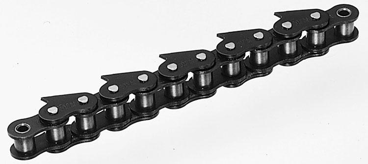


77 lus ttachment Chain Specification ttachments Examples of Specification ttachments lus igh recision Conveyor Chain Engineering Manual 76

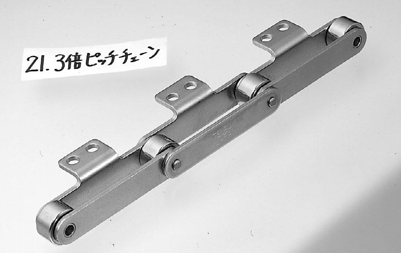


78 lus α ttachment Chain Specification ttachments lus α Engineering Manual 25 igh recision Conveyor Chain


79 lus igh recision Conveyor Chain Engineering Manual 78


80 igh recision Conveyor Chain Bearing Bush Chain subaki Bearing Bush Chain enables chains to be used in conveyance systems considered impossible up to now. Ideal for automated, laborsaving, or high-speed applications for improved productivity. RF-B Series RF-B RF-B-SS Steel needles placed between the pin and bush; steel base chain (link plates only are nickel-plated) 1. Initial elongation (0.02%) is less than bearing cage chain. hereafter, there is no wear elongation. See graphs below. 2. wealth of custom configurations is available to meet your needs. 3. Operating temperature range: -10 C to 150 C igh-precision specification 1. op surfaces of attachments are ground smooth. 2. Link plates are nickel-plated except for top surfaces of attachments. 3. Space between bushes and rollers is smaller. 4. Operating temperature range: -10 C to 150 C Stainless steel 1. ll parts except needles are stainless steel. 2. Bearings are sealed to allow use where dripping water is present. 3. Minimum chain wear elongation. See graphs below. 4. Operating temperature range: -10 C to 60 C /igh-recision Specifications Bush eedle Roller Stainless Steel Specifications RF-B (standard specification) RF-B (high-precision specification) lus igh recision Conveyor Chain Engineering Manual 79 Wear Elongation Diagram pplication Examples rocess ssembly Inspection ackaging Filling rinting in Space between pin and bush is filled with grease Virtually no chain wear elongation after initial elongation (0.02%) following start of operation. Chain Wear Elongation (%) Equivalent to two years on actual equipment Material/Object Conveyed Condensers, cassettes, batteries, stoves, automotive parts, limit switches, watches, solenoid valves ICs, cables, automotive parts rocessing Medical products, cables, building material boards Brushes, batteries, confections Detergent Beverage containers, drinking glasses, printed materials Wear Elongation Diagram umber of Cycles umber of Cycles 107 Chain Wear Elongation (%) [est Conditions] Seal Space between pin and bush is filled with grease. Seal prevents grease from leaking out. Wear elongation is just 0.06% after 10 7 flexing cycles, an extremely low value. Equivalent to two years on actual equipment /igh-recision/stainless Steel Specifications Chain size: RF2040R Chain tension: /igh-recision = 0.78 k {80 kgf} Stainless Steel = 0.44 k {45 kgf} Chain speed: 70 m/min (accelerated test) Sprocket teeth: umber of links: 44 Continuous operation Selection Example: Calculating umber of Cycles from ctual Conditions Chain: RF2040R umber of links: 232 links=5,892.8 mm Feed length per takt time=101.6 mm/1.1 second Sprocket teeth: 12 x 12 ssuming 4 flexing cycles per chain revolution: herefore, the number of cycles in two years (8 hours/day x 300 days/year) under the above conditions yields: 5,892.8 mm101.6 mm 1.1 seconds = 63.8 seconds/revolution 60 seconds 63.8 seconds60 minutes8 hours300 days2 years4 cycles = cycles
81 Bearing Cage Chain RF-C 1. Virtually no chain wear elongation after initial elongation (0.03%) following start of operation (see graph below). 2. Operating temperature range: -10 C to 60 C Bush eedle Roller in Space between pin and bush is filled with grease Wear Elongation Diagram Chain Wear Elongation (%) umber of Cycles 10 7 Mini act Chain Custom designs and manufacturing are available to match your application needs. lease contact a subakimoto representative for more information. BCM Uses a needle bearing cage (of engineering plastic) between the pin and bush; steel base chain (outer plates are blackened; inner plates are nickel-plated) Uses steel needle bearings; aluminum inner blocks and steel base chain 1. Virtually no chain wear elongation after initial elongation (0.01%) following start of operation. 2. Chain pitch accuracy is 0.05 mm. lus, small pitch makes this chain ideal for accurate positioning of small work. 3. luminum inner blocks mean lighter weight, enabling a compact design that includes drive components. 4. Operating temperature range: -10 C to 40 C [est Conditions] Chain model: RF2040R-C Chain tension: 0.44 k {45 kgf} Chain speed: 70 m/min (accelerated test) Sprocket teeth: umber of links: 44 Continuous operation BC Indexing able Chain Uses needle bearings; outboard rollers and guide rollers use steel bearings; steel base chain (links are blackened) 1. Virtually no chain wear elongation after initial elongation (0.01%) following start of operation. 2. Chain pitch accuracy is 0.05 mm, enabling high positioning accuracy. 3. Operating temperature range: -10 C to 60 C wo types of outboard rollers are available: single (S) and double (D). Double outboard rollers (D type) draw the guide rail up to the sides of the sprockets, enabling smooth conveyance. his type is for general applications. Single outboard rollers (S type) are used as replacements when this type is currently in use. lus igh recision Conveyor Chain Engineering Manual 80
82 igh recision Conveyor Chain Bearing Bush Chain Base Chain /igh-recision Chain Stainless Steel Chain L1 L2 D Connecting Link h R W L1 L2 D Connecting Link h R W Connecting links: RF2050 and RF2080 use cotter pins. Base chain pins are riveted on all sizes. ttachments 2 ttachment K2 ttachment 2 ttachment K O K O K O K2 ttachment K O X S C X2 X X S C C X2 X2 X S C X2 X X S C C X2 X2 lus igh recision Conveyor Chain Engineering Manual Base Chain/ttachment Dimensions subaki Chain o. igh- recision itch Width Between Inner Link lates W hickness RF2040R-B RF2040R-B { 80} 0.99 RF2050R-B RF2050R-B {130} 1.72 RF2060R-B RF2060R-B {180} 2.57 RF2080R-B RF2080R-B {300} 3.88 subaki Chain o. igh- recision S C XX2 K O 2 K2 RF2040R-B RF2040R-B 9.1( 8.9) RF2050R-B RF2050R-B 11.1(10.9) RF2060R-B RF2060R-B 14.7(14.4) RF2080R-B RF2080R-B 19.1(18.8) ote: Dimension S differs for igh-recision chain, and is given inside parentheses. subaki Chain o. itch Roller Dia. R Width Between Inner Link lates W late Width h ttachment Width pprox. Mass kg/m dditional Weight per ttachment kg Max. late in pprox. llowable Mass Load Width h Width Dia. D L1 L2 kg/m k {kgf} Stainless Steel hickness RF2040R-B-SS { 45} 1.06 RF2050R-B-SS { 70} 1.82 RF2060R-B-SS {105} 2.68 RF2080R-B-SS {180} 4.07 subaki Chain o. Stainless Steel Roller Dia. R ttachment dditional Weight per ttachment kg S C X X2 K O 2 K2 RF2040R-B-SS RF2050R-B-SS RF2060R-B-SS RF2080R-B-SS in Dia. D L1 L2 Max. llowable Load k {kgf} 81
83 igh recision Conveyor Chain Bearing Cage Chain Base Chain L1 L2 h D ttachments K O 2 ttachment K O K2 ttachment X S C X2 X X S C C X2 X2 R W Connecting links: RF2040 to RF2060 use spring clips. Base Chain Dimensions subaki Chain o. itch Roller Dia. R ttachment Dimensions Width Between Inner Link lates W hickness Max. late in pprox. llowable Mass Load Width h Width Dia. D L1 L2 kg/m k {kgf} RF2040R-C { 45} 0.99 RF2050R-C { 70} 1.72 RF2060R-C {105} 2.57 RF2080R-C {180} 3.88 subaki Chain o. ttachment dditional Weight per ttachment kg S C XX2 K O 2 K2 RF2040R-C RF2050R-C RF2060R-C RF2080R-C lus igh recision Conveyor Chain Engineering Manual 82
84 igh recision Conveyor Chain Bearing Bush Chain, Bearing Cage Chain Sprockets RF Double itch sprockets for R rollers can be used. lus igh recision Conveyor Chain Max. llowable Loads for Bearing Bush Chain (B) and Bearing Cage Chain (C) subaki Chain o. RF2040R RF2050R RF2060R RF2080R recautions for Use Lubrication (Unit: k {kgf} per attachment or per roller) llowable 2 ttachment Load llowable Roller Load Outer late Inner late C/B/B Specification B-SS Specification 0.12{12} 0.18{18} 0.47{48} 0.72{73} 0.03{ 3} 0.05{ 5} 0.13{13} 0.21{21} 0.15{15} 0.20{20} 0.29{30} 0.54{55} 0.05{ 5} 0.06{ 6} 0.09{ 9} 0.15{15} 1. Chain speed must be less than 30 m/minute. 2. Operating temperatures: Bearing Cage Chain: -10 C to 60 C Bearing Bush Chain (/igh-recision): -10 C to 150 C Bearing Bush Chain (Stainless Steel): -10 C to 60 C 3. Chain must be handled carefully when the pins have been removed, for example, while connecting the chain, as the needles in the bearings (or in the needle cage) may fall out. he space between the pin and bush is filled with grease, but the sprocket teeth and the gap between the bush and roller should be lubricated with ISO VG100 to VG150 (SE30 to SE40) machine oil. Chain umbering Bearing Bush Chain () RF2040R-B-1L2 Chain size Roller type (R only) Chain type B: B: igh-recision Bearing Bush Chain Custom Shape Examples riangle ttachment rofile of attachment is matched to the shape of the conveyed objects, which are cradled by the attachment as they are conveyed. Outboard Rollers SS: Stainless Steel C: Bearing Cage Custom ttachments Custom itches ress ut Stay in Metric itch (Single itch Bush ype) uts are added on the attachment. Enables jigs or tools to be installed easily. type only. Guide Rollers ttachment type ttachment spacing ins are extended to form parallel strands. llows wider objects to be conveyed. type only. Multiple Strands Chain pitch is the same as roller chain. Generally interchangeable with roller chain. (owever, certain sizes may not fit. lease inquire for details.) Dust-roof type chain having metric pitch (in mm). rovides chain pitches matched to indexing distances. ote: sprockets are required. Custom Extended ins hreaded Extended in Extended pins are threaded to enable tools, jigs, etc., to be attached. S Rollers (with Bushes) Base chain rollers are S rollers (with bushes). Interchangeable with double pitch S roller chain. Can be replaced with Double itch Chain S rollers. ot available in all sizes. lease contact a subakimoto representative for more information. Engineering Manual 83 Outboard rollers are mounted on one or both sides. Installing outboard rollers stabilizes chain travel. lso, building bearings into the outboard rollers enables even higher precision conveyance. Installing guide rollers enables side surface guiding and horizontal conveyance. lease inquire regarding use of the stainless steel type in environments where chain would be exposed to water. Can be fabricated in multiple strands, for example, doublestrand or triplestrand configurations. For applications where the maximum allowable tension of a single strand is inadequate. type only. ote: sprockets are required. seal is incorporated into the bearing components. revents bearings from being contaminated by foreign substances.
, Effective Depth: 7 mm, hrough ilot ole M3 hrough-ole Model: BCM15-9 (15 mm pitch) pproximate Chain Mass: 25 g/2 links Maximum llowable ension: 0.")
85 igh recision Conveyor Chain Mini act Chain Model: BCM (12.5 mm pitch) pproximate Chain Mass: 19.4 g/2 links Maximum llowable ension: 0.3 k {30 kgf} Direction of ravel 3.0 mm-dia. ole (reamed), Effective Depth: 7 mm, hrough ilot ole M3 hrough-ole Model: BCM15-9 (15 mm pitch) pproximate Chain Mass: 25 g/2 links Maximum llowable ension: 0.3 k {30 kgf} Direction of ravel wo M3 oles, 3 mm Deep Endless Loop Operating emperature Range: 10 C to 40 C Chain Speed: Less than 30 m/min (recommended range) subaki can design and manufacture these chains to match your application and requirements. lease contact us when considering indexing conveyor chain. Chain umbering BCM Chain type Chain pitch 12.5 mm 15 mm Inner width dimension Endless Loop Sprockets (for BCM Chain) Drive Sprocket Four M3 oles, apped wo M4 oles, apped wo 5-mm-Dia. oles, Drilled Driven Sprocket M4 ole, apped Four M3 oles, apped (7-mm-dia. countersunk) With ex Socket ead Bolts (M3 x 8L) D B D O D Material: Steel DB DO D lus ote: Drawings show 12-tooth sprockets, but 16-tooth sprockets are also available. ll dimensions are the same as above. subaki Chain o. BCM BCM15-9 Sprocket o. BCM D 12 BCM BCM D 16 BCM BCM15-9 D 12 BCM BCM15-9 D 16 BCM ype Drive Driven Drive Driven Drive Driven Drive Driven o. of eeth Sprocket itch Dia. D Outside Dia. DO Dia. DB Facewidth Root Circle pprox. Mass kg Material lastic + steel lastic lastic + steel lastic lastic + steel lastic lastic + steel lastic igh recision Conveyor Chain Engineering Manual 84
 and double (D). Double outboard rollers draw the guide rail up to the sides of the sprockets, enabling smooth conveyance. his type is for general applications.")
86 igh recision Conveyor Chain Indexing able Chain Specifications Link plate material: Carbon steel Link surface treatment: Blackened Outboard rollers: wo types of outboard rollers are available: single (S) and double (D). Double outboard rollers draw the guide rail up to the sides of the sprockets, enabling smooth conveyance. his type is for general applications. Single outboard rollers are used as replacements when this type is currently in use. subaki Chain o. S BC050 D 45 S BC075 D 60 S BC100 D 70 S BC150 D 90 ote: llowable speed is index pitch (mm) index time (seconds) Chain umbering BC050S45 Chain type Chain pitch itch mm Mass/Link kg Outboard roller type S: Single D: Double Width between link plates Max. llowable Load per Link k/link {kg/link} llowable Load k {kgf} llowable Speed mm/s lus Chain Outside Dimensions (Single Roller) BC050S45 Direction of ravel Reference Surface for Mounting ools/jigs 4-M4 Screws BC075S60 Direction of ravel Reference Surface for Mounting ools/jigs 4-M5 Screws igh recision Conveyor Chain BC100S70 Direction of ravel BC150S90 Direction of ravel Engineering Manual Reference Surface for Mounting ools/jigs 4-M6 Screws Reference Surface for Mounting ools/jigs 4-M8 Screws 85

87 Chain Outside Dimensions (Double Roller) BC050D45 BC075D60 Direction of ravel Direction of ravel BC100D70 Direction of ravel 4-M4 Screws BC150D90 Direction of ravel 4-M5 Screws ote: Made-to-order product. ote: Same sprockets are used for Single Roller and Double Roller types. 4-M6 Screws Sprockets (for BC Chain) Specifications ooth profile: round tooth profile Material: Carbon steel for machine structural use Surface treatment: Blackened vailable ypes Sizes: 50, 75, 100, and 150 mm widths umber of teeth: 8 or 12 subaki Chain o. S BC050 D45 S BC075 D60 S BC100 D70 S BC150 D90 Sprocket o. BC BC BC BC BC BC BC BC o. of eeth Sprocket Dimensions Dp Do D1 D2 D3 W M ote: he size and shape of bore diameter (d) and hub diameter (D) are determined by conveyor layout. lease indicate D D3 D2 Mass kg W 4-M8 Screws M M d D D1 DO Moment of Inertia lkgm 2 GD 2 kgfm {0.02} 0.02 {0.08} 0.025{0.1} 0.13 {0.5} 0.085{0.34} 0.4 {1.6} 0.52 {2.1} 2.4 {9.6} lus igh recision Conveyor Chain Engineering Manual 86
88 87 MEMO

89 Engineering Manual Chain Selection 89 Conveyor Design Guidelines94 Installation 97 ow to Cut Chain98 ow to Connect Chain100 Lubrication101 ension djustment 102 rial Run 103 Inspection103 Usage Limits104 Other recautions 104 roubleshooting105 lus igh recision Conveyor Chain Engineering Manual 88
90 Engineering Manual Chain Selection lus igh recision Conveyor Chain Engineering Manual 89 n appropriate chain size and type can be selected based upon the type and capacity of the conveyor. In some cases, it may be difficult to determine the most appropriate chain size and type, since there are a variety of operating conditions for the conveyor. he general procedure for chain selection is as follows: Step 1: Check Conveyance Conditions Step 2: entatively Determine Chain ype Step 3: Check llowable Load Step 4: Calculate Max. Chain ension Step 5: Determine Chain Size Step 6: ow to Select Indexing Chain Step 1: Check Conveyance Conditions 1) ype of conveyor (slat conveyor, bucket elevator, etc.) 2) Method of chain travel (horizontal, inclined, or vertical conveyor) 3) ype, mass, and size of materials to be conveyed 4) Conveyor capacity, interval between conveyed objects 5) Conveying speed 6) Conveyor length 7) Lubrication status 8) Considerations for special environments (high/low temperature, presence of corrosive substances) Step 3: Check llowable Load he load applied to rollers or attachments should not exceed the allowable loads shown in able 1 and able 2. able 1: Base Chain llowable Roller Load subaki Chain o. subaki Chain o. Double itch Chain* Double itch ttachment () Lambda/X-Lambda R Roller S Roller Stainless Steel Chain RF { 26.7} 0.108{11.0} RF { 46.4} 0.189{19.3} RF {108 } 0.419{42.7} RF {170 } 0.646{65.9} RF {256 } 1.15{117 } RF {375 } 1.79{183 } RF {596 } 3.13{319 } Stainless Steel Roller (SS, S) ttachment Chain* { 2.9} 0.012{ 1.2} { 9.6} 0.036{ 3.7} { 13.3} 0.054{ 5.5} { 24.8} 0.101{ 10.3} { 38.3} 0.148{ 15.1} { 60.3} 0.233{ 23.8} { 95.1} 0.361{ 36.8} {142 } 0.629{ 64.1} {186 } 0.869{ 88.6} {241 } 1.19 {121 } * Includes corrosion-resistant chain (/E series). eat-resistant Low-oise lastic Roller lastic Roller lastic Roller oly Steel Chain {0.5} {1.5} RF { 65} 0.15{ 15} 0.20{ 20} 0.05{ 5} 0.20{ 20} 0.20{ 20} 0.14{14} 0.02 {2.0} RF {100} 0.20{ 20} 0.29{ 30} 0.06{ 6} 0.29{ 30} 0.29{ 30} 0.21{21} 0.04 {4.0} RF {160} 0.29{ 30} 0.49{ 50} 0.09{ 9} 0.49{ 50} 0.49{ 50} 0.34{35} 0.06 {6.0} RF {270} 0.54{ 55} 0.79{ 80} 0.15{15} 0.88{ 90} 0.62{63} RF {400} 0.79{ 80} 1.17{120} 0.25{25} 1.27{130} RF {600} 1.18{120} {135} RF {980} 1.91{195} able 2: ttachment llowable Load Double itch Chain Unit: k {kgf}/attachment Unit: k {kgf}/attachment Unit: k {kgf}/roller ote: 1. Values are for lubricated chain. Values for Double itch and ttachment Chain include corrosion-resistant chains (/E series). 2. Values for oly Steel Chain are for the case in which the roller supports the bottom surface of the inner link. 3. he material used for standard R roller guide rail should be a high tensile strength material at least S45C (JIS), 1045 (ISI) or better. 4. See page 83 for details on Bearing Cage Chain and Bearing Bush Chain. ote: * Includes corrosion-resistant chain (/E series). See page 83 for details on Bearing Cage Chain and Bearing Bush Chain. Chain subaki Chain o. R Roller S Roller R Roller R Roller R Roller Stainless Steel Chain Step 2: entatively Determine Chain ype Use the following formula to determine maximum static chain tension (F) for tentative selection of chain type. G SI Units: F(k)Wf1KVG m/s 2 Gravimetric Units: F{kgf}=Wf1KV W: otal mass {weight} of conveyed objects on conveyor kg {kgf} f1: Coefficient of friction (able 3)KV : Speed coefficient (able 4) entatively select a chain that has maximum allowable tension of F (for two parallel strands, use F X 0.6) or more. Base Chain llowable Roller Load Load llowable Roller Load (per roller) 1) he mounting hole of an attachment is regarded as the point where the allowable vertical load acts on the attachment. 2) For K attachments, double the values shown for attachments. 3) Load should not exceed maximum allowable roller load. Load
91 Step 4: Calculate Max. Chain ension (F) In this catalog, values are indicated in both SI and gravimetric units. he weight (kgf) used to calculate the max. tension in the gravimetric units is the same value as the mass (kg). F : Max. static tension applied to chain : k {kgf} able 3-1: f1: Coefficient of Rolling Friction of Base Chain Rollers on Rail V : Conveying speed (chain speed) : m/min Low-oise Bearing lastic : Center distance between sprockets (vertical direction) : m Roller Steel Roller Lambda lastic Bush Roller* ype Chain Roller Chain L : Center distance between sprockets (horizontal direction) : m Dry Lubricated Dry Dry C : Center distance between sprockets : m M : Mass {weight} of moving parts R roller (chain, bucket, apron, etc.) : kg/m {kgf/m} S roller W : otal mass {weight} of conveyed objects on conveyor * Includes heat-resistant plastic rollers. (max. value) : kg {kgf} able 3-2: f1: Coefficient of Rolling Friction of Chain lates on Rail For countable items: W = C Mass {weight} of conveyed items Steel late Loading interval oly Steel Chain kw: ower required Dry Lubricated f1 : Coefficient of friction between chain and guide rail (able 3) : ransmission efficiency of drive unit G : cceleration of gravity: m/s Formula SI Units orizontal Conveyance Goods are directly loaded on the conveyor {Gravimetric Units} G FW 2.1MCf kw FV X11X 60 1 L(=C) FW2.1MCf1 kw FV X11X Vertical Conveyance G FWMC 1000 G kw WV X11X 1 (=C) FWMC kw WV X11X lus Inclined Conveyance* Goods are directly loaded on the conveyor F C 1.1MLf1 WMCLf1 G 1000 G kw V F M Lf1 X11X 1 C L FWMC Lf1 1.1MLf1 C kw V 6120 F M Lf1 X11X 1 * When calculating the value for F, if Lf1 <0, make Lf1 =0. lso when calculating the value for kw, if Lf1<0, make Lf1=0. igh recision Conveyor Chain Engineering Manual 90
92 Engineering Manual SI Units {Gravimetric Units} orizontal/inclined Conveyance* Goods are directly loaded on the conveyor C1 C2 L1 lus igh recision Conveyor Chain Engineering Manual F W 2.1MC1f1 W ML1f1 C1C2 C1C2 kw V 60 F M L1f1 G 1000 X11X 1 * When calculating the value for F, if Lf1 <0, make Lf1 =0. lso when calculating the value for kw, if Lf1<0, make Lf1=0. FKVMax. llowable ension able 4: Speed Coefficient (Kv) Chain Speed (m/min) Speed Coefficient (Kv) Chain Speed (m/min) Speed Coefficient (Kv) 15 or less to to to G ML1f1 Step 5: Determine Chain Size 70 to to to F W 2.1MC1f1 W ML1f1 C1C2 C1C2 1.1ML1f1 kw V 6120 FM L1f1 X11X 1 Multiply the maximum tension (F) applied to a chain by the speed coefficient (Kv) given in able 4 for a chain that satisfies the following formula: able 5: Strength Double itch Unit: k {kgf} Double itch Chain subaki Chain o. Chain verage ensile Strength Min. ensile Strength Max. llowable Load RF2040 (S,R) 16.7{ 1700} RF2050 (S,R) 27.5{ 2800} RF2060 (S,R) 40.2{ 4100} RF2080 (S,R) 68.6{ 7000} RF2100 (S,R) 108 {11000} RF2120 (S,R) 151 {15400} RF2160 (S,R) 258 {26300} 14.7{ 1500} 23.5{ 2400} 35.3{ 3600} 60.8{ 6200} 93.2{ 9500} 133 {13600} 230 {23500} 2.65{ 270} 4.31{ 440} 6.28{ 640} 10.7 {1090} 17.1 {1740} 23.9 {2440} 40.9 {4170} he recommended speed of the following chains is as follows: Bearing Cage Chain Bearing Bush Chain Indexing able Chain, Mini act Chain lastic Roller Chain oly Steel Chain : 30 m/min or less : 70 m/min or less : 70 m/min or less Lambda Chain (Including /E Series), X-Lambda Chain Lambda Chain, X-Lambda Chain subaki Chain o. verage ensile Strength Min. ensile Strength Max. llowable Load RF2040 (S,R) 15.7{ 1600} 13.8{1410} 2.65{ 270} RF2050 (S,R) 25.5{ 2600} 21.8{2220} 4.31{ 440} RF2060 (S,R) 37.3{ 3800} 31.1{3170} 6.28{ 640} RF2080 (S,R) 63.7{ 6500} 55.6{5670} 10.7 {1090} RF2100 (S,R) 100 {10200} 86.7{8840} 17.1 {1740} (Maximum llowable Load) Stainless Steel Double itch Chain Surface-reated Double itch Chain subaki Chain o. SS S S LSC E RF2040 (S,R) 0.44{ 45} 0.69{ 70} 0.44{ 45} 0.44{ 45} 2.65{ 270} RF2050 (S,R) 0.69{ 70} 1.03{105} 0.69{ 70} 0.69{ 70} 4.31{ 440} RF2060 (S,R) 1.03{105} 1.57{160} 1.03{105} 1.03{105} 6.28{ 640} RF2080 (S,R) 1.77{180} 2.65{270} 1.77{180} 1.77{180} 10.7 {1090} RF2100 (S,R) 2.55{260} 17.1 {1740} RF2120 (S,R) 3.82{390} 23.9 {2440} RF2160 (S,R) 6.37{650} 40.9 {4170} 2.65{ 270} 4.31{ 440} 6.28{ 640} 10.7 {1090} 17.1 {1740} 91
93 lastic Roller Chain (Maximum llowable Load) subaki Chain o. Series Low-oise Series eat-resistant SS SS Series RF2040 (R) 0.44{ 45} 0.44{ 45} 0.44{ 45} 0.44{ 45} 0.44{ 45} 0.44{ 45} 0.44{ 45} RF2050 (R) 0.69{ 70} 0.69{ 70} 0.69{ 70} 0.69{ 70} 0.69{ 70} 0.69{ 70} 0.69{ 70} RF2060 (R) 1.03{105} 1.03{105} 1.03{105} 1.03{105} 1.03{105} 1.03{105} 1.03{105} RF2080 (R) 1.77{180} 1.77{180} 1.77{180} 1.77{180} 1.77{180} 1.77{180} RF2100 (R) 2.55{260} 2.55{260} 2.55{260} ollow in Chain (Maximum llowable Load) Curved Chain (Maximum llowable Load) subaki Chain o. Lambda SS subaki Chain o. RF2040 (S,R) 1.77{180} 1.47{150} 1.77{180} 0.44{ 45} RF2040 (S,R) 1.86{190} RF2050 (S,R) 3.14{320} 2.55{260} 3.14{320} 0.69{ 70} RF2050 (S,R) 2.84{290} RF2060 (S,R) 4.22{430} 3.43{350} 4.22{430} 1.03{105} RF2060 (S,R) 4.02{410} RF2080 (S,R) 7.65{780} 6.18{630} 7.65{780} 1.77{180} RF2080 (S,R) 6.96{710} igh recision Conveyor Chain Bearing Bush Chain (Maximum llowable Load) subaki Chain o. B B-SS RF { 80} 0.78{ 80} 0.49{ 45} RF {130} 1.27{130} 0.69{ 70} RF {180} 1.77{180} 1.03{105} RF {300} 2.94{300} 1.77{180} Mini act Chain Indexing able Chain subaki Chain o. Max. llowable Load subaki Chain o. Max. llowable Load BCM {30} BC050 (S,D) { 50} BCM {30} BC075 (S,D) { 70} Chain Unit: k {kgf} BC100 (S,D) { 70} BC150 (S,D) {130} Bearing Cage Chain subaki Chain o. Max. llowable Load RF2040 (S,R) 0.45{ 45} RF2050 (S,R) 0.69{ 70} RF2060 (S,R) 1.03{105} RF2080 (S,R) 1.77{180} ttachment Chain Chain subaki Chain o. verage ensile Strength Min. ensile Strength Max. llowable Load { 420} 3.63{ 370} 0.64{ 65} { 960} 7.9 { 805} 1.52{ 155} { 1700} 27.5 { 2800} 40.2 { 4100} 68.6 { 7000} 14.7 { 1500} 23.5 { 2400} 35.3 { 3600} 60.8 { 6200} 2.65{ 270} 4.31{ 440} 6.28{ 640} 10.7 {1090} {11000} 93.2 { 9500} 17.1 {1740} {15400} {20800} {26300} {14000} {18000} {23500} 23.9 {2440} 32.4 {3300} 40.9 {4170} Lambda Chain (Including /E Series), X-Lambda Chain Lambda Chain X-Lambda Chain subaki Chain o. verage ensile Strength Min. ensile Strength Max. llowable Load verage ensile Strength Min. ensile Strength Max. llowable Load { 960} 7.9{ 805} 1.52{ 155} { 1600} 13.8{1410} 2.65{ 270} 15.7{ 1600} 13.8{1410} 2.65{ 270} { 2600} 21.8{2220} 4.31{ 440} 25.5{ 2600} 21.8{2220} 4.31{ 440} { 3800} 31.1{3170} 6.28{ 640} 37.3{ 3800} 31.1{3170} 6.28{ 640} { 6500} 55.6{5670} 10.7 {1090} 63.7{ 6500} 55.6{5670} 10.7 {1090} {10200} 86.7{8840} 17.1 {1740} 100 {10200} 86.7{8840} 17.1 {1740} (Maximum llowable Load) subaki Chain o. Stainless Steel ttachment Chain Surface-reated ttachment Chain oly Steel SS S S LSC E Chain 25 (25C) 0.12{ 12} 0.12{ 12} 0.64{ 65} 0.08{ 8} 35 (35C) 0.26{ 27} 0.26{ 27} 1.52{ 155} 0.18{18} 40 (40C) 0.44{ 45} 0.69{ 70} 0.44{ 45} 0.44{ 45} 2.65{ 270} 2.65{ 270} 0.44{45} 50 (50C) 0.69{ 70} 1.03{105} 0.69{ 70} 0.69{ 70} 4.31{ 440} 4.31{ 440} 0.69{70} 60 (60C) 1.03{105} 1.57{160} 1.03{105} 1.03{105} 6.28{ 640} 6.28{ 640} 0.88{90} {180} 2.65{270} 1.77{180} 1.77{180} 10.7 {1090} 10.7 {1090} {260} 17.1 {1740} 17.1 {1740} {390} 23.9 {2440} {470} 32.4 {3300} {650} 40.9 {4170} ollow in Chain (Maximum llowable Load) Curved Chain (Max. llowable Load) subaki Chain o. Lambda SS subaki Chain o {180} 1.47{150} 1.77{180} 0.44{ 45} {190} {320} 2.55{260} 3.14{320} 0.69{ 70} {290} {430} 3.43{350} 4.22{430} 1.03{105} {410} {780} 6.18{630} 7.65{780} 1.77{180} {710} ote: SS and S chains are not pre-lubricated before shipping. lways lubricate the chain before use, except when using underwater or when the chain will contact water. Using a chain without lubrication may result in premature articulation problems. Maximum allowable loads are based on lubricated (including water lubricated) conditions. lus igh recision Conveyor Chain Engineering Manual 92
94 Engineering Manual Step 6: ow to Select Indexing Chain When selecting chain for indexing operations using indexing equipment, in addition to the normal tension based on F (tension from frictional force), the added tension from inertia (F1) must be taken into account when calculating the total tension acting on the chain. In general, this additional tension F1 is found from the formula F1 = m. he steps to calculate chain tension based on this formula are explained below. m: otal mass on driven side (kg) : Maximum acceleration (m/s 2 ) SI Units {Gravimetric Units} Mass {weight} of conveyed object W kg {kgf} Driven-side sprocket mass {weight} M2 kg {kgf} otal mass {weight} of moving parts of chain (jigs, etc.) M1 kg {kgf} lus igh recision Conveyor Chain 1) Find total mass m on driven side. 1) Find total mass m on driven side. mwm1 1 M2 2 m 1 WM1 1 M2 G 2 G : cceleration of gravity = (m/s 2 ) 1 ote: M2 is an approximate calculated value for the inertial force of the sprocket 2 converted to the mass (weight) of the chain. 2) Find the additional tension from inertia from F1 = m based on the maximum acceleration (m/s 2 ) and the formula in 1) above. For example, when using a cam indexing system, able 6: Relationship Between Cam Curves and m maximum acceleration can be found by using ame m the following formula: Modified sine curve (MS) 5.53 = m(m/s L 2 ) t 2 Modified trapezoidal curve (M) 4.89 L: Indexing length of 1 takt (m) Modified sine constant velocity (MSC) 8.01 t: Indexing time of 1 takt (s) For details, check with the manufacturer of the indexing equipment. m: Dimensionless maximum acceleration (able 6) Use the value for m corresponding to the cam curve. 3) Find F, the total working tension taking the additional tension due to inertia into consideration. FFF11000 F: Chain tension based on frictional force (k) (Maximum static tension) 3) Find F, the total working tension taking the additional tension due to inertia into consideration. FFF1G F: Chain tension based on frictional force (kgf) (Maximum static tension) Engineering Manual 4) Determine chain size FKvMaximum allowable tension Kv: Speed coefficient (able 4) 5) Check the allowable roller load of the chain. 93
95 Conveyor Design Guidelines 1. Conveyor System and Roller ype (able 7) Conveyor System Roller ype Comments Chain Rolling (horizontal, inclined) Double itch Chain Chain Rolling Chain Sliding Double itch Chain R Roller ype eavy in chain weight Greater allowable roller load Less roller wear S Roller ype Lightweight Lower allowable roller load 2. Conveyor rrangement (able 8) ake-up Guide Roller, Idler Drive Shaft Smooth operation and vibrations are small. ower required is low since frictional resistance is small. Center distance between sprockets should be generally over 10 m. pplicable for speeds over 20 m/min. Center distance between sprockets should be generally less than 10 m. pplicable for speeds under 20 m/min. Resistant to loading shocks and bad environments; however, the rail damages quickly. Construction is simple. ower required is large. Both the conveying and return sides are supported by rails. he most recommended and streamlined layout. sag is produced on the take-off side of the sprocket. he return side is supported by guides, rollers, or idlers. Since the chain bends when it comes into contact with the rollers or guides, an increase in friction occurs, allowing for easy wear. lso, vibrations of the chain exert a bad effect on overall running. Consequently it is not desirable to have a long center distance between sprockets. he return side is not supported. he tension due to the mass of the chain on the return side produces vibrations causing rough conveying. Examples showing slat conveyors and a cross rod conveyor that are most commonly used: he slat is installed using the attachment and the rollers roll over the rails on both the conveying and return sides. he slat is installed using the K attachment. In comparison to the above example, this type of arrangement is suitable for wide slat conveyors where the mass of the conveyed goods is heavy. owever, on the return side the slat slides on the rail. his is a cross rod conveyor where a pipe is installed by means of an E attachment, GK attachment, or ollow in Chain. he rollers roll on the rails on both the conveying and return sides. 3. Use of at igh/low emperatures s a general rule, standard small size conveyor chain can be operated in clean air environments and in ambient temperatures between -10 C and 60 C. When the chain is operated in environments outside this range, the following points should be taken into consideration. 1. Operation at very low or high temperatures: Chain must be selected or used in a different manner when it is operated in freezing chambers, cold areas, when it passes through dryers or heat-treatment furnaces, or when it is affected by heat from the material being conveyed. able 9 below provides guidelines for the relationship between allowable tension and temperature for standard chains. able 9: emperature Corrected Working Load emperature Range -30 C to -20 C -20 C to -10 C -10 C to 150 C 150 C to 200 C 200 C to 250 C llowable ension (Max. allowable load in catalog) x 0.25 (Max. allowable load in catalog) x 0.33 (Max. allowable load in catalog) x 1.0 (Max. allowable load in catalog) x 0.75 (Max. allowable load in catalog) x 0.5 able 10: emperature Environment and oints of Concern emperature Usage Conditions otential roblems Range -50 C to -30 C -30 C to -10 C 60 C to 150 C 150 C to 250 C 250 C to 400 C Under -30 C or lower conditions, corrosion-resistant SS and S stainless steel chains are suggested. steel chains cannot be used. steel chain should be selected on the basis of the corrected working load, above (able 9). lubrication is required. Because wear resistance is reduced in this temperature range, selection of the next larger pitch chain size over the one originally selected to reduce bearing pressures is suggested. When standard chain is to be used, evaluate whether or not the chain can be used at a reduced allowable tension (see able 9 above). Corrosion-resistant SS and S stainless steel chains are suggested. (1) Low-temperature embrittlement may occur on standard steel chain, reducing impact resistance. (2) Congealing of lubricant. (3) Rust due to condensation. (4) Seizure due to frost formation. (1) Excessive wear due to decrease of hardness of pin and bush. (2) Excessive elongation due to softening. (3) oor lubrication and chain seizure due to deterioration of lubricant. (4) Excessive wear and chain seizure due to formation of scale. 4. Lubricants and igh/low emperatures low-temperature or high-temperature lubricants are required if a chain will be exposed to temperatures outside the range of 10 C to 60 C. See page 101 for details on recommended lubricants. lus igh recision Conveyor Chain Engineering Manual 94

 Decrease in fatigue strength from rust and corrosion (pitting) of the chain. Countermeasures Reduce bearing pressure using a larger sized chain to improve wear resistance.")
96 Engineering Manual lus igh recision Conveyor Chain Engineering Manual 5. Cautions on Use in Environments s a general rule, conveyor chain should be used in clean air environments. When used in a special environment, reference should be made to the following items. 1. Use in Wet Conditions If the chain is splashed with water or goes through heated vapor, the following problems may occur. 1) Increase in wear elongation due to improper or insufficient lubrication. 2) Decrease in fatigue strength from rust and corrosion (pitting) of the chain. Countermeasures Reduce bearing pressure using a larger sized chain to improve wear resistance. Use corrosion-resistant small size conveyor chain for rust prevention. 2. Use in cidic or lkaline Conditions If the chain is exposed to acids or alkaline conditions, such as battery acid and liquid used in plating processes, the following problems may occur. 1) Embrittlement fracture of link plates and pins. 2) Fatigue breakage of link plates and pins due to rust and pitting corrosion. 3) Wear from usual mechanical abrasion and corrosion. 4) Reduction in volume of the whole chain from corrosion. 5) In special cases where the chain is underwater (immersed in liquid), electrochemical corrosion may occur. 6) here are also circumstances where even stainless steel chain will corrode. he photograph below shows an example of chain that was used in a plating apparatus. he chain fell to pieces within one month due to the effects of acid. Corrosion of Stainless Steel Drive Chain Countermeasures for Embrittlement Fractures (stress corrosion cracking) dopt a brittleness countermeasure that lowers crack susceptibility. Install a cover or casing to prevent acids or alkalis from contacting the chain. dopt a high-grade material with anti-corrosive properties. Countermeasures for Corrosion Use surface-treated attachment chain. Install a cover or casing to prevent acids or alkalis from contacting the chain. dopt a high-grade material with anti-corrosive properties. In general, embrittlement fractures (stress corrosion cracking) occur around the link plate holes. his is the area where the pin and bush are press-fitted to the link plate having the highest concentration of stress. Cracks occur even when there is no tension on the chain. Conveyor chain in general is more susceptible to acids than alkalis, and in special cases, embrittlement fractures (stress corrosion cracking) are generated by seawater or pit water. ydrogen Embrittlement Cracking 3. Use Under Conditions Where brasion Is a roblem If the chain is exposed to strong abrasive materials that promote wear such as sand, coke, and metal particles, the following problems may occur. 1) When abrasive materials penetrate between the pins and bushes, chain wear is promoted and poor articulation occurs. 2) When abrasive materials penetrate between the bushes and rollers, chain wear is promoted and poor roller rotation occurs. 3) When abrasive materials penetrate between the link plates, poor articulation occurs. Countermeasures pply a dust-protection casing. Remove foreign particles by regularly washing the chain. Reduce bearing pressure using a larger sized chain to improve wear resistance. dopt a chain that has specially processed parts where abrasion is a problem. 95
97 6. Other recautions 1) o keep long conveyors consistently operating in top condition, use take-up devices to eliminate chain slack. ake-up stroke = (center distance between sprockets X 0.02) + catenary sag allowance he 0.02 factor represents a 2% allowable wear elongation of chain. 2) Chain must always be engaged with at least three sprocket teeth. 3) When operating with multiple strands of conveyor chain, sprockets should be mounted on the same shaft and all sprocket teeth should be properly aligned. 4) When operating a long conveyor with two or more strands of chain, and when especially high pitch accuracy is required, subaki can provide specially configured chain to minimize the relative difference in length. lso, special sprockets can be manufactured to ensure that sprocket teeth are properly aligned. 7. Corrosion Resistance Guide for Corrosion Resistant Chains and Sprockets (able 11) Corrosion resistance varies accordingly depending on application conditions. his table should not be considered a guarantee. Using this table as a reference, be sure to check the corrosion resistance of the chain in advance according to actual operating conditions in determining chain type. able 11 Chemical, Food roduct Roller Chain Sprocket Engineering lastic SS S S I C C- SY SS cetone 20 C Oils (vegetable, mineral) 20 C Linseed oil 100%20 C B Sulfur dioxide (wet) 20 C lcohol (methyl, ethyl, propyl, butyl) queous ammonia Whiskey Ether (ethyl ether) Zinc chloride 20 C 20 C 20 C 50%20 C B B B B mmonium chloride 50%Boiling point B B otassium chloride Saturated20 C B Calcium chloride 20 C B B B Ferric chloride 5%20 C B B B Sodium chloride 20 C B ydrochloric acid 2%20 C Chlorine gas (dry) 20 C B B B Chlorine gas (wet) 20 C B Chlorine water Oleic acid Seawater 20 C 20 C B B B Sodium perchlorate 10%Boiling point ydrogen peroxide Gasoline 30%20 C 20 C B otassium permanganate Saturated20 C Formic acid Milk Citric acid Glycerin 50%20 C 20 C 50%20 C 20 C Creosote 20 C Chromic acid Ketchup Developer (photo) Synthetic detergent Coffee Cola syrup 5%20 C 20 C 20 C Boiling B B cetic acid Sugar solution 10%20 C 20 C B Calcium hypochlorite (bleaching powder) vailable chlorine 11 to 14% 20 C B Sodium hypochlorite 10%20 C B Sodium cyanide 20 C Carbon tetrachloride (dry) 20 C otassium dichromate 10%20 C Oxalic acid artaric acid itric acid mmonium nitrate 10%20 C 10%20 C 5%20 C Saturated boiling B B B Chemical, Food roduct otassium nitrate 25%20 C 25%Boiling point Vinegar 20 C otassium hydroxide (caustic potash) 20%20 C Calcium hydroxide (hydrated lime) 20% Boiling Sodium hydroxide (caustic soda) 25%20 C Stearic acid 100% Boiling point Soft drinks 20 C Carbolic acid 20 C etroleum 20 C Soapy water 20 C Carbonated water Sodium hydrogen carbonate 20 C Sodium carbonate Saturated boiling point Sodium thiosulfate 25% Boiling point urpentine oil 35 C Kerosene 20 C Varnish Concentrated nitric acid 65%20 C Boiling Lactic acid 10%20 C oney, syrup araffin 20 C Beer 20 C icric acid Saturated20 C Fruit juice 20 C Benzene 20 C Boric acid 50% 100 C Formalin (formaldehyde) 40%20 C Mayonnaise 20 C Water Vegetable juice 20 C Lard Butyric acid 20 C ydrogen sulfide (dry) ydrogen sulfide (wet) Sulfuric acid 5%20 C Zinc sulfate 25Saturated20 C luminum sulfate Saturated20 C mmonium sulfate 20 C Sodium sulfate Saturated20 C Malic acid 50%50 C hosphoric acid 5%20 C 10%20 C Wine 20 C Roller Chain SS S S I C C- SY Sprocket Engineering lastic SS B B B B B B B B B B B B B B B B B B Chemical, Food roduct cetone Oils (vegetable, mineral) lcohol queous ammonia Sodium chloride ydrochloric acid (2%) Seawater ydrogen peroxide Caustic soda (25%) Gasoline Formic acid Formic acid aldehyde Milk Lactic acid Citric acid Chromic acid (10%) cetic acid (5%) Carbon tetrachloride otassium hydroxide Sodium hydroxide (20%) itric acid (5%) Vinegar ypochlorite soda Soft drinks Soapy water araffin Beer Fruit juice Wine Whiskey Benzene Water Vegetable juice Iodine Sulfuric acid hosphoric acid (10%) (Steel Chain) B B B B B : otally resistant B: artially resistant (depending on operating conditions) : ot resistant : Unknown For information on KV rollers, please contact a subakimoto representative. lus igh recision Conveyor Chain Engineering Manual 96
98 Engineering Manual lus 1. Sprocket Installation roper installation of the sprockets is critical to smooth operation of a conveyor, and it also affects chain life. he installation should be properly carried out in accordance with the procedure described below. 1) Check the horizontal positioning of the shafts with a level. djust the level to within the tolerance of. 1 Level 300 Figure 1: orizontal ositioning of Shafts 2) Check the parallelism of the shafts with a scale. djust the shafts so that the parallelism as calculated with a formula B 1 is to within. L 100 Level Measure with a piano wire or a scaled transit instrument Figure 2: arallelism of Shafts 3) lign the sprocket axis to match. olerance relative to center distance: Up to 1 m: within1 mm Distance between shafts (mm) 1 to 10 m: within m or longer: within10 mm B Shaft Shaft Measure misalignment with: straight edge when the distance is short piano wire when the distance is long leveling string or a piano wire when the sprocket positions are different from each other in terms of height Misalignment L Sprocket Installation Shaft 3. Rails In general, rails wear faster than chain. While it is important that the rail material be matched to the chain material, in general, rolled steel for general structures (SS400) or plastic material (ultra-high molecular weight polyethylene) is recommended. 1) Wear is a complex phenomenon and is influenced by a variety of factors, including corrosion, lubrication, load speed, and operating time. Deducing the precise relationship between chain life and rail material is difficult. 2) Chain life is influenced by the rail. For new installations, verify the wear state by selecting rail material that is slightly softer than the chain. he smoother the finish on the rail surface, the better. 3) Operating conditions must be taken into consideration when selecting materials. In environments involving mechanical impact and other special conditions, there may be cases when plastic should not be used. 4) recautions before putting rails into operation 1. Lubricate all rail connecting parts, chamfer edges, and eliminate uneven levels and gaps. (See Figure 4.) 2. fter welding rail, remove sputter or scale. 3. During the trial run, run the conveyor unloaded. Lubricate the chain and check the condition of chain and rails. Rail Width W Rail width W is generally set to the sprocket facewidth. Examples of Good Design W W Examples of oor Design W Uneven Level igh recision Conveyor Chain Engineering Manual 97 Figure 3: Sprocket Misalignment 4) fter processes 1) to 3) have been completed, lock each of the sprockets to the shaft(s) by means of keys or subaki OWER-LOCKS. Lock the sprockets that are installed and used on the same shaft so that the teeth of both sprockets align in terms of phase. 2. Centering Because the conveyor chain runs on a guide rail, the precision of the guide rail must be especially high and the conveyor properly centered. In cases like vertical bucket elevators where there are no guide rails, if the conveyor is not precisely centered, the chain will wobble and weave. his will have a significant impact on the life of the conveyor chain. Spaces are required to account for heat expansion of the rail. Figure 4: Rail Joints R Figure 5: Chain Entrance/Exit from Guide Rail W Large Gap o ensure that the chain moves smoothly, bend the guide rail to a radius of R at the points where the chain engages and disengages from the rail.
. Configuring chain to a specific length will require cutting units. 1. Grinding Riveted in Using a grinder, grind down the ends of the two pins on the outer link (on the attachment side) until they are level with the outer plate.")

99 ow to Cut Chain ttachment chains are generally sold in 1-unit sections (1 unit = 10 ft/3,048 mm). Configuring chain to a specific length will require cutting units. 1. Grinding Riveted in Using a grinder, grind down the ends of the two pins on the outer link (on the attachment side) until they are level with the outer plate. ake care that the grinder does not overheat (see Figures 6 and 7). articularly in the case of Lambda Chain, work on the chain slowly so that the oil-impregnated bush does not become too hot. Grind down the riveted heads of the pins until they are level with the outer plate. Whichever method is used, support blocks should be placed under the chain on either side of the vise to ensure that the chain remains stable (Figure 10). ny attachment can be cut using this method. owever more force will be required to remove the pin as mentioned in 3. in Removal on the next page. Support Block Cradle Support Block Figure 6: ttachment Chain Figure 7: Grinding Down in Ends Figure 10: Cradle and Support Blocks in to Be Removed 2. Setting Chain on Vise and Cradle 1) S Roller (, S, E, GK1 attachments) lace the chain in the jaws of the vise with the attachment side facing up and gently tighten the vise to secure the chain (Figures 8 and 9). Cradle Figure 11-1: Cradle Cross Section Chain Vise Figure 11-2: Chain Vise Usage Figure 8: Setting Chain in Chain Vise ttachment Chain Vise Figure 9: Cross Section of Chain Set in Chain Vise 2) S Roller (K, SK attachments), R Roller (K, SK attachments), lastic R Roller, oly Steel Chain (with attachments) For these types, the chain is set in a cradle (Figure 11-1). nother method, used only for steel S rollers (Figure 11-2), is to set the pin to be removed on the edge of the chain vise. 3) R Roller (, S, E attachments) his method cannot be used for plastic rollers. Secure the non-attachment side plate of the chain in the vise and support the R rollers on the vise (Figure 13). Ensure that the chain is supported on both sides of the vise (Figure 12). Support Block Chain Vise Figure 12: Chain Vise and Support Blocks ttachment Chain Vise Support Block lus igh recision Conveyor Chain Engineering Manual Figure 13: Cross Section of Chain Set in Chain Vise 98
 Using a primary punch suitable for the chain size (refer to the subaki Drive Chain ccessories section in a separate catalog), place the punch on the head of the pin that was ground down")
100 Engineering Manual 3. in Removal 1) Using a primary punch suitable for the chain size (refer to the subaki Drive Chain ccessories section in a separate catalog), place the punch on the head of the pin that was ground down and strike with a hammer. Be sure to strike the pins on the outer link alternately to remove them evenly and at the same time. Strike the pins until they are just about to release from the outer plate (Figure 14). 4. oly Steel Chain (Without ttachments) 1) lace the outer plate of the chain in the cradle, position the special punch on the head of the pin (see photo in Figure 16 below), and lightly strike with a hammer (Figure 15). 2) Work carefully, as there is a risk of damage if excessive force is applied to engineering plastic components in this process. rimary unch Outer late Vise Cradle Figure 15: Cross Section Showing oly Steel Chain Set in Cradle lus Figure 14: apping in with rimary unch 2) Using a secondary punch (refer to the subaki Drive Chain ccessories section in a separate catalog) and a hammer, completely remove the pair of pins from the outer link. Check that the bush of the removed pins has not come loose from the inner plate, and that the bush has not become deformed in the process. If the bush has come loose or is deformed, do not continue to use it. Figure 16: Disconnecting oly Steel Chain Safety oints 1. Use the grinder to grind down only the riveted portion of the pin head. Removing the pin without grinding the riveted head off will require additional time and effort, and may damage the chain. 2. Do not re-use parts removed from the chain. igh recision Conveyor Chain Engineering Manual 99
101 1. ssembling with a Connecting Link 1) Insert the pins of the connecting link into the bushes of the free inner links. lace the free link plate over the pin ends and secure using a spring clip or cotter pins. 2) he pins are slip-fit into the connecting plate, meaning the pins can be inserted manually. Inner Link Spring-Clip ype Connecting Links: Chain sizes RF2040 to RF2060, and 25 to 60 in Groove ow to Connect Chain Connecting late Spring Clip Cotter-in ype Connecting Links: Large chain sizes RF2080 and above, and 80 and above Connecting late Cotter in 3) In general, the spring clip should be installed in the direction opposite to chain travel, as shown in the drawing below (Figure 21). Direction of ravel Figure 21: Spring Clip Installation 3. Installing Cotter ins Securely install the cotter pins in the holes provided on the ends of the pins. Failure to install the cotter pins or improper installation may result in an accident. 1) fter the cotter pin has been fully inserted into the hole on the end of the pin, open the legs of the cotter pin to an angle of around 60 (Figure 22). Do not re-use cotter pins. Do not use commercially available cotter pins. Figure 17: ow to Connect ttachment Chain 2. Installing Spring Clips Check that the spring clip is securely attached. Failure to install the spring clip or improper installation may result in an accident. 1) Spring clips are used to secure the connecting link of chain sizes smaller than RF2060 and 60. Insert the pins of the connecting link into the bushes of the free inner links, place the link plate over the pin ends, and slide the spring clip over the ends of the pins so that the slot and the fingers of the clip engage the grooves securely (Figures 18 and 19). 2) ay careful attention to ensure that the fingers of the spring clip are not spread too wide. If the spring clip does not fit securely, it could become detached without warning, leading to an accident (Figures 19 and 20). Figure 18: Slide Spring Clip Over Grooves in in Ends Figure 22: Open Legs of Cotter in 2) ow to Open the Legs of the Cotter in ead of Cotter in Leg of Cotter in Figure 23 (1) Insert the cotter pin into the cotter pin hole. (2) Use a pin that is somewhat larger in diameter than the cotter pin to lightly tap the head of the cotter pin. he legs of the pin will open slightly. Flathead screwdriver lus Spring Clip (leg) Figure 19: Use a air of liers to Secure Spring Clip Figure 20: Spring Clip Installed Correctly Spring Clip in Figure 24 (3) Insert the blade of a flathead screwdriver at the point where the legs of the cotter pin have opened slightly. Caution erform this operation with extreme care! If the end of the screwdriver slips, it could puncture the hand or cause other injury. Figure 25 (4) Insert the blade of the flathead screwdriver at an angle and move the screwdriver back and forth to open the legs of the cotter pin. (5) ress down the head of the cotter pin tightly so that the cotter pin will not disengage from the cotter pin hole. (6) Bend the cotter pin legs to the 60 angle mentioned above. igh recision Conveyor Chain Engineering Manual 100
102 Engineering Manual Lubrication roper lubrication of roller chain is essential for peak performance and full chain life. In particular, the greater the level of performance demanded of the chain, the more the need for lubrication increases. 1) he purpose of lubrication is to reduce wear on chain parts, prevent corrosion (rust), and economize on power demands. 2) Lubricate the chain periodically (about once a week) so that the chain always remains damp with oil. erform drip lubrication (using lube listed below) or apply lube with a brush. 3) Lubrication locations Since wear between pins and bushes causes chain elongation, lubrication must be maintained on all contact surfaces. lso, areas where chain parts (plates, etc.) come into contact with guide rails must be lubricated (see Figure 26). Lubricate this area when Bush plates slide on rail Outer late Figure 26: Lubrication points Lubricants: SE umbers (able 12) Lubrication Method Drip or Brush mbient emperature subaki Chain o. -10 C to 0 C 0 C to 40 C 40 C to 50 C 50 C to 60 C 50 or lower small-pitch chain SE10W SE20 SE30 SE40 in Inner late Roller 60/80 SE20 SE30 SE or higher large-pitch chain SE30 SE40 SE50 Commercially vailable Lubricants (able 13) SE SE10W SE20 SE50 SE30 SE40 SE50 lus Manufacturer ISOVG (CS40 C) Idemitsu Kosan Exxon Mobil Japan Energy (JOMO) Showa Shell Sekiyu 32 Daphne Mechanic Oil 32 DE Oil Light Lathus 32 Super MULUS DX eavy medium eavy Extra heavy BB JX ippon Oil & Energy Eneos FBK Oil RO igh recision Conveyor Chain Examples of Lubrication at Low and igh emperatures (able 14) he following lubricants can be applied when conveyor chain is used at low or high temperatures. Regarding other brands, use an equivalent. mbient and Operating emperature -50 C to -25 C -25 C to 0 C -10 C to 60 C 60 C to 200 C 150 C to 250 C Engineering Manual Manufacturer/ Lubricant Dow Corning oray S510 Shin-Etsu Chemical KF50 Momentive erformance Materials SF431 Exxon Mobil rctic Oil C eavy See above Sato Oil ot Bearing Oil #200 Exxon Mobil DE Oil Moresco Moresco ilube L-150 Sato Oil igh hermo Lube #700 Moresco Moresco ilube R
103 ension djustment he correct amount of chain slack is essential for proper operation of the chain. When the chain is too tight, working parts such as chain, sprocket wheel, shaft, bearings, etc., carry a much heavier load, accelerating chain wear. On the other hand, too much slack is also harmful and causes the chain to climb the sprocket teeth. 1. Frequency of djustment he chain has a tendency to stretch a certain amount at the beginning of operation due to slight distortion of its components. fter such initial elongation, the chain stretches slightly, but constantly, as a result of normal wear. o maintain proper chain tension, adjustments, if necessary, should be made at regular intervals. ssuming eight hours of operation a day, the frequency schedule for inspection and adjustment is given in the table below. When working hours are increased, the frequency of adjustment should be increased accordingly. eglect of careful inspection increases the chances of an accident. 2. Insufficient ake-up djustment If there is still excessive slack in the chain even after the take-up adjustment is fully tightened, shorten the chain by removing two links. See page 98, ow to Cut Chain for the steps involved. ake-up 1st week after start of operation 2nd to 4th week after start of operation hereafter Once a day wice a week wice a month Some Slack Drive 3. Even djustment of ake-up on Both Sides Where two parallel chains are adjusted by two independently operated take-ups, care must be taken to ensure even stroke on both the left and right side (not needed when the take-ups are cooperating screw type or counterweight type). n uneven adjustment will cause the link plate and the side of the sprocket teeth to interfere with each other and result in an overload condition. When the right and left sides are uneven, the two chains should be made even by replacing a portion of the right and left chains. lus he angle of wrap between the chain and drive sprocket should be at least 120, or the chain must always be engaged with at least three sprocket teeth. ake-up Figure 27: djusting Chain Slack Drive igh recision Conveyor Chain Engineering Manual 102
104 Engineering Manual rial Run fter installing the chain, carry out a trial run and check the following items before you actually start running the chain. lus igh recision Conveyor Chain Engineering Manual 1. Before rial Run 1) Connecting spring clips and cotter pins are installed correctly. 2) Chain slack is adjusted properly. 3) Lubrication is adequate. 4) he chain does not come into contact with casing or covers. Inspection Frequently inspect the chain during the initial operating period in order to carry out necessary adjustment. Inspect the following items. 1) Unusual wear of chain. 2) Slack in chain. 3) Vibration and jerking of chain. 4) Unusual wear of sprocket, unusual contact of sprocket with other components due to eccentricity, dust accumulated on root of teeth. When the sprocket properly engages with the chain, even contact is represented by the trace of contact shown as in the illustration, while uneven trace of contact as B in the illustration represents improper installation of the sprocket or a twisted chain. Rechecking is needed. roper contact should be traced a little above the root. owever, when initial tension remains in the slacked side of the chain, the chain slightly contacts Figure 28: race of Contact the root. owever, even in this case, strong contact should be traced around. In the case of idlers and tighteners, contact happens at the middle of the root. 5) oo much wear of guide rail. 6) ny abnormality in the lubricating system. 2. rial Run 1) here are no strange noises. 2) here is no excessive chain vibration. 3) he chain does not run up on the sprockets. 4) he chain is not jammed into the sprockets. 5) he rails and sprockets are installed correctly. 6) he rollers rotate smoothly. 7) here are no stiff areas during chain articulation. Caution n unloaded trial run should be conducted after installation by intermittently switching the system on and off several times. fter inspection, a continuous unloaded trial run should be conducted. rior to the trial run, be sure to lubricate the chain to allow lubricant to work into various components. Causes of Vibration, Jerking, and Unusual Wear 1) Overload, glass fragments caught between components. 2) Warping of the chain on the return side. 3) Insufficient lubrication or no lubrication. 4) Wear of the sprocket. 5) Unusual wear or breakage of the chain. 103
105 1. Chain Wear Elongation he chain should be measured by stretching it slightly to remove any backlash or looseness. Measure the distance of the inside (L1) and outside (L2) of rollers at both ends of the measured links to obtain measurement (L). When measuring, use at least 6 to 10 links to help keep any measuring error to a minimum. L1 L Measured length (L) length Chain wear elongation (%) = x 100% length length = Chain pitch X o. of links he chain should be replaced when wear elongation is greater than 2% of the chain pitch. chain wear measurement scale that allows easy checking of pitch stretch is available from subaki. For Lambda Chain, if the chain elongation reaches around 0.5%, then the oil has run out. Indicators of this condition are red wear dust between the plates and occurrence of poor chain articulation. In this situation the chain is no longer usable and should be replaced. 2. R Rollers When wear between the bush and roller causes the under surface of the link plate to contact the guide rail, the chain has usually reached the end of its usable service life. When the link plate starts contacting the guide rail, rolling contact suddenly turns into sliding contact between the link plate and rail, resulting in greater wear, an increase in chain tension, and a reduction in transmitted power. Usage Limits 3. S Rollers he chain has reached the end of its service life as soon as holes or cracks appear on the rollers due to wear. 4. Link lates For conveyor configurations in which link plates move directly on the material to be conveyed or on a guide rail, the service life has come to an end when the worn section equals /8, as shown in the drawing. Figure 30: late Width Wear 5. Sprockets When the sprocket is worn as illustrated below (to the left), the chain is prone to being caught by the tips of the teeth (), making the departure of the chain from the sprocket difficult, hence resulting in vibration of the chain. hough wear allowance depends on the type of conveyor and the size of the chain to a certain extent, if the sprocket is replaced when the wear reaches 0.3 to 1.0 mm, damage to the chain can be avoided. When the sprocket is worn in the direction of the facewidth as illustrated below (to the right), the shaft may not be properly aligned, therefore correct it. Wear Wear Figure 32: Wear of Sprocket eeth 1. Shutdown/Restart Stop the conveyor under no-load conditions to prevent remaining material from overloading the system when the conveyor starts again. lso, if the conveyor system has been shut down for a long period of time, be sure to inspect the chain before restarting. 2. Securing Conveyor arts arts fastened to the conveyor such as buckets, aprons, slats, etc., tend to loosen as a result of vibration. ay careful attention to fastening nuts and bolts, and check periodically that they are tightly fastened. 3. emperature and revention of Freezing Conveyor damage may occur when differences in temperatures (between day and night in winter) are extreme. Under these circumstances, operate the conveyor carefully, taking into account any variations in temperature as well as appropriate lubrication, the moisture content of the conveyed material, inspections, etc. 4. Spare Chain Storage In the unlikely event of a failure or accident, we recommend that a spare chain be prepared in advance. his spare chain should be stored in a dry space. lso, if the chain is to be stored for a long period of time, it should Other recautions be coated with a rust-preventive oil. For convenience, attach a tag noting the product name, model number, date of purchase, and equipment it is intended to be used on. 5. Record of Use and Maintenance Beyond the maintenance and inspection items mentioned above, after installing the conveyor, prepare a record of the expected capacity to be conveyed, conveying speed, r/min. of main shaft, electric current, voltage, power, working hours, actual conveying capacity, inspection dates, lubricating dates, details of problems, and the like. his will serve as protection against unexpected accidents. When updated on a regular basis, this record will also be convenient for maintenance and repairs. 6. Cleaning he chain should be cleaned periodically to remove contamination or particles of conveyed material from the chain and rail. 7. Storage of Chain and Sprockets Chain and sprockets should be stored in a place free of dust and dirt and where they will not be exposed to rain. o prevent rust, use a brush to coat sprockets with oil. o rust-prevention treatment is applied at the time chain is shipped. herefore, when storing chain, coat with a rustpreventative oil and inspect periodically for corrosion. lus igh recision Conveyor Chain Engineering Manual 104
106 Engineering Manual roubleshooting When there is significant damage and breakage to the chain and sprockets, please carry out the following procedures. 1. General Symptom ossible Causes Remedy he chain and sprocket do not match. Excessive load. Elongation of the chain due to wear or excessively worn sprocket teeth. ngle of chain wrap on the sprocket is insufficient. Replace the chain and sprocket with the correct size. Reduce the load, add lubrication, or increase the number of strands or the size of the chain. Replace with new chain and sprockets. ngle of chain wrap should be at least 120 or chain must be engaged with at least three sprocket teeth. Chain rides up on the sprocket Inadequate back-tension. Distance between the center of the chain and the sprocket do not match. Improper installation of the sprocket or shaft. djust the catenary or take-up idler. Inspect and correct. Inspect and correct. Chain casing or bearings are loose. Excessive or insufficient slack in the chain. Excessively worn chain or sprocket. ighten all bolts and nuts. djust the distance between the shafts to obtain the proper amount of slack. Replace with new chain and sprockets. lus Unusual noises Lack of or unsuitable lubrication. Interference of casing with the chain or other moving parts. Improper guide rail installation. Difference in Rail Levels rovide proper lubrication according to the operating conditions. Inspect and correct. igh recision Conveyor Chain Return Radius R Excessive slack in the chain. Rails ilted or Skewed Inspect and correct. djust the chain length or distance between shafts. Install a tensioner. Engineering Manual Chain winds onto the sprocket (poor separation from the sprocket teeth) Elongation of the chain due to wear or excessively worn sprocket teeth. he chain and sprocket do not match. oor chain articulation due to rust. Inappropriate lubrication. arsh environment. Replace with new chain and sprockets. Replace with new chain and sprockets. Remove and replace the chain. rotect the chain from the environment by appropriate lubrication and/or cover. 105

107 Symptom ossible Causes Remedy Improper installation. Correct sprocket and shaft installation. Excessive wear on the inside surface of the link plates and sides of the sprocket teeth he chain is being pushed to the side. Remove the cause of the push and/or switch to a chain with guide rollers. Excessive wear on the sides of the link plates and pin heads Improper installation of guides, etc. Deformation of the chain caused by improper installation. Check the condition of the guides and increase the gap between the guides and the chain. Inspect installation and correct as necessary. Contamination from metal dust or dirt because of improper lubrication. Excessive load, bent pin, or cracked bush. Corrosion or rusting. Remove the chain, wash it thoroughly, and provide proper lubrication. Reduce the load or increase the number of strands or the size of the chain. Install a chain casing to protect the chain. Improper flex or bending of the chain Spreading of link plates Inadequate lubrication. Foreign particles stuck in clearance. Use in extremely high temperatures. Uneven or excessive load caused by improper installation. rovide adequate lubrication. Install a casing to protect the chain. rovide adequate clearance. (Consult with subaki regarding this situation.) Replace with new chain and correct installation. lus igh recision Conveyor Chain Engineering Manual 106


, which are perpendicular to the direction of pull Deformation of link plate holes Loads are greater than allowable.")
 Fatigue Fracture By repeatedly applying a load past its fatigue limit (fatigue strength), the fatigue will start at holes and then suddenly cause")
 Offset Link late Fatigue Offset link plates are bent at the center, and the resulting concentration of stress at the bend can cause a fatigue break.")

108 Engineering Manual 2. Link lates Symptom ossible Causes Remedy Breakage of link plate Excessively large shock load. Vibration in the chain. Corrosion. Reduce shock loads by making start-up, stopping, and other actions smoother. Install a shock absorber. Increase the number of strands or the size of the chain. Install an anti-vibration device such as a tensioner or idler. Replace with new chain. Install a casing to protect the chain. eriodically clean and lubricate the chain. lus 1) Static Fracture Stretching the link plate with a tensile load beyond its breaking load will cause it to stretch and then break. Cracks in the link plates (fatigue), which are perpendicular to the direction of pull Deformation of link plate holes Loads are greater than allowable. Excessive load. 2) Fatigue Fracture By repeatedly applying a load past its fatigue limit (fatigue strength), the fatigue will start at holes and then suddenly cause the chain to break. Repetitive load on attachments. 3) Offset Link late Fatigue Offset link plates are bent at the center, and the resulting concentration of stress at the bend can cause a fatigue break. void using offset links in highpressure applications. Remove all large or excessively repetitive loads. Increase the number of strands or the size of the chain. Reduce excessive loads. Increase the size of the chain to increase the allowable load of the attachments. Replace with new chain. Remove the cause of the excessive load. igh recision Conveyor Chain Engineering Manual Corrosion stress cracks (bow-shaped cracks in the link plate) he chain is being used in an acidic or alkaline environment (not caused by repetitive loads). Replace with new chain. Install a casing to protect the chain from the environment. Consider a chain with a high resistance to corrosion stress crack. 107


 Shock-Induced Bending Fracture he pin is subjected to a large shock load and breaks.")

109 3. ins Symptom ossible Causes Remedy Breakage of pin Excessively large shock load. Subject to a repetitive load greater than the fatigue limit of the pin. Corrosion. Reduce shock loads by making start-up, stopping, and other actions smoother. Remove the large repetitive load. Increase the number of strands or the size of the chain. Install a casing to protect the chain. eriodically clean and lubricate the chain. 1) Static Fracture he type of fracture found when subjecting the chain to the breakage test. Occurs when the chain is subjected to a load greater than its breakage strength. in rotates or begins to stick out ormal 4. Bushes/Rollers Symptom ossible Causes Remedy Roller and/or bush cracks (falls) Roller does not rotate, roller is corroded on one side Excessive load or improper lubrication. Operating a chain at high load without proper lubrication can create friction between the pin and bush, causing the pin to rotate. In this condition, the pin may come out, leading to chain breakage. Inadequate lubrication. 25, 35 Foreign particles have gotten between the bush and roller. Excessive load on the rollers. articles of the conveyed material or other foreign particles have built up on the frame. Rust on the bush and rollers. he inner plate is moving inward. 2) Fatigue Fracture Occurs when the pin is repetitively subjected to loads greater than its fatigue limit. Recheck the size of the peak load and formulate a countermeasure. he inner link plate is moving inward, or the bush is cracked. 3) Shock-Induced Bending Fracture he pin is subjected to a large shock load and breaks. he side with the initiating point receives tensile load and the fracture progresses from this point. he pin is especially susceptible to becoming weak with regard to bending when the surface of the pin has corroded. his type pf phenomenon occurs quite easily. Replace with new chain. Improve the lubrication or loading conditions. Replace with new chain immediately. Do not weld or reuse the pins. Dispose of the old chain to be sure that it is not used again by mistake. lso, if the pin head or link plate surface is worn, check the installation. rovide adequate lubrication according to the operating conditions. Replace with new chain. hese are bushed chains and have no rollers. Replace with new chain. Re-inspect the installation and load conditions. eriodically clean the chain. Install a casing to protect the chain. Reduce excessive loads. Increase the size of the chain. eriodic cleaning. Install a partition to protect the chain. Select the appropriate specifications (materials). Replace with new chain. Re-inspect the installation and load conditions. Roller is opening up Excessive load. Reduce the load. rovide adequate lubrication. lus igh recision Conveyor Chain Engineering Manual Roller is becoming hourglass shaped Excessive load or inadequate lubrication. Replace with new chain. Improve the lubrication or loading conditions. 108


110 Free Flow Chain Double itch Free Flow Chain Double lus Chain Center Roller Chain Free Flow Conveyor his is a conveyor system where the speed of conveyed objects can be freely controlled and stopped at any time and at any position for accumulation or for performing a job at a station without stopping the conveyor. 2.5x Speed his unique construction combining the use of small and large rollers allows high-speed transfer at 2.5 times the speed of the chain. Low oise he lower chain speed allows accumulation with low noise. Snap Cover ype Double lus Chain Operating temperature range: -10 C to 60 C Steel Roller ype ccessories for Double lus Chain he snap cover prevents small parts from falling into the frame. Operating temperature range: -10 C to 60 C Steel Roller type is capable of higher-load conveyance compared with plastic roller chain. It is operable at temperatures as high as 150 C and achieves quiet operation. Operating temperature range: -10 C to 150 C Outboard Roller Chain op Roller Chain pplications Double lus Chain is intended for high-speed conveyance. he use of a special rail minimizes chain exposure and thus improves safety. his chain is widely used for assembly and inspection lines in a variety of business fields, such as the automobile and electronics industries. Same Speed he speed of the chain and conveyed objects is the same ratio of 1:1. Center Roller Chain Stable Conveyance Sprockets Engineering Manual 109 Center Roller Chain allows stable conveyance, as its center of gravity is lower than that of op Roller Chain and conveyed items are received on rollers on both sides. Snap Cover ype he snap cover prevents small parts from falling into the frame. Operating temperature range: -10 C to 60 C pplications Operating temperature range: -10 C to 150 C Center Roller Chain is intended for low-speed conveyance. Steel Roller type is suitable for conveying heavier objects and can be used for conveyance in a furnace.
 is also available. (See page 132.")

111 Double itch Outboard rollers allow for a more compact conveyor. With its many outboard rollers, this chain is suitable for conveyors on which small objects are placed directly on the conveyor. Double itch Chain ype Chain with tab guide attachments (SG) is also available. (See page 132.) Chain ype oly Steel Chain ype Outboard Roller Chain Double lus Chain Center Roller Chain ccessories for Double lus Chain pplications Outboard Roller Chain is used for low-speed conveyance of objects of various sizes in a wide range of business areas. he width of the chain is smaller than that of other types of Free Flow Chain. With top rollers supported by plates on both sides, this chain is suitable for use with rugged free-flow conveyors. op Roller Chain Outboard Roller Chain op Roller Chain Double itch Chain ype Chain ype Double-strand op Roller type and topple prevention attachment type (G) are available. (See pages 140 and 142.) pplications op Roller Chain is used for low-speed conveyance and is widely adopted in the automobile industry. With its wide roller width, Double-Strand op Roller Chain is suitable for conveying heavier objects directly placed on the conveyor. Sprockets Engineering Manual 110

 Same Speed and Stable ransfer D")
 Sprockets Engineering Manual op Roller Chain R (age 135) Smaller Chain")
112 Free Flow Chain Double itch Free Flow Chain Specifications R S Double lus Chain Double lus Chain VR VR (age 113) igh-speed ransfer and Low oise Center Roller Chain Engineering lastic ccessories for Double lus Chain Outboard Roller Chain Free Flow Chain Double lus Chain with Snap Cover VR-SC VR-SC (age 118) Center Roller Chain B igh Friction C Electro- Conductive revents Small arts from Falling into Frame (igh-speed transfer and low noise) Same Speed and Stable ransfer D Electro-Conductive igh Friction U, UB Urethane Lining VR Steel CR (age 119) op Roller Chain Outboard Roller Chain SR Smallest Dimension in a Vertical Direction (age 125) Sprockets Engineering Manual op Roller Chain R (age 135) Smaller Chain Width in a orizontal Direction 111
 (Urethane lining) vailable only for Steel RF2030VR.")
 (Urethane lining) vailable only for RF2030VR.")
 (Urethane lining) vailable only for RF2030VR.")


 Steel KV Engineering lastic Steel Lubrication required on steel outboard rollers.")

113 Double itch Base Chain* Large Roller & Small Roller Related Components Steel nti corrosive Steel + ard Chrome lating C B C D U UB (Work placed directly on conveyor) (Urethane lining) vailable only for Steel RF2030VR. B C D Sprocket for Double lus Chain luminum Frame Double lus Chain nti corrosive Lube free, low noise Stainless Steel Steel + Oil-impregnated bush Steel SS LMC U UB (Work placed directly on conveyor) (Urethane lining) vailable only for RF2030VR. B C D luminum Frame with Steel Rail luminum Frame for Drive and Driven Sections Center Roller Chain nti corrosive Steel + ard Chrome lating C U UB (Work placed directly on conveyor) (Urethane lining) vailable only for RF2030VR. Steel B C D allet Guide Rail & lastic Rail ccessories for Double lus Chain nti corrosive Lube free, low noise Stainless Steel Steel + Oil-impregnated bush SS LMC Steel ote: Center Roller Chain with Snap Cover is also available. U UB (Work placed directly on conveyor) (Urethane lining) vailable only for RF2030VR. Steel Return Guide Bracket Frame Joint Outboard Roller Chain Lightweight, low noise Lube free, low noise Lightweight, low noise Lightweight, lube free, low noise Lightweight, low noise With steel or plastic R roller Steel + Oil-impregnated bush With stainless steel or engineering plastic roller Stainless steel + Engineering plastic C inner link Steel Steel + lastic R roller LMC Outboard Roller Engineering lastic Electro-Conductive Engineering lastic (anti-static) Steel KV Engineering lastic Steel Lubrication required on steel outboard rollers. Engineering lastic Stainless Steel Engineering lastic op Roller Engineering lastic Stainless Steel KV Engineering lastic * Base Chain Refers to the part of the chain, excluding the large rollers, small rollers, outboard rollers, and top rollers for the sake of explanation. Engineering lastic Roller Refers to a roller made of engineering plastic. op Roller Chain Sprockets Engineering Manual Lube free, low noise Steel + Oil-impregnated bush LMC KV Steel Lubrication required on steel top rollers. 112
114 Free Flow Chain Double lus Chain (Industrial roperty, Utility Model Registration o ) Double itch Construction ype, C ype, SS ype Lambda ype () (Under patent application) Double lus Chain (On both sides) Connecting Link Outer late Inner late Bush Large Roller Small Roller (On both sides) Connecting Link Outer late Inner late Bush Large Roller Small Roller Bush Center Roller Chain ccessories for Double lus Chain Outboard Roller Chain arts marked with are press fit. Other parts are slip fit. Connecting late Spring Clip Double lus Chain with Snap Cover Snap Cover for Outer Link (Utility Model Registration o ) Snap Cover for Inner Link Connecting late Spring Clip arts marked with are press fit. Other parts are slip fit. Uses a special oil-impregnated bush. he bush is press-fitted into the inner plate. he pin is treated with a special nickel plating. he inner and outer plates are treated with a black oxide finish. Urethane Lining Roller ype Large Roller with Urethane Lining (exterior) op Roller Chain Small Roller olyacetal (interior) RF2030VRU, RF2030VRUB Differs from Double lus Chain shown above only in the large roller. Sprockets Double lus Chain with Snap Cover differs from the Double lus Chain shown above only in terms of the shape of the plate on which the snap cover is installed. he snap cover is detachable. Double lus Chain with Snap Cover is available in hard chrome plating, stainless steel, and Lambda types, as well as the standard type. Engineering Manual 113
. he same combination is also allowed for Double lus Chain with Snap Cover.")
 (Base chain is the same as the standard type) pplications where lubrication is not permitted or not preferable VR Engineering lastic Roller VRB igh Friction VRC")
115 Combination of Base Chain and Roller Double itch he proper combination of base chain (4 types) and roller (7 types) allows the optimum selection for your intended purpose (he mark in the table below shows an allowable combination). he same combination is also allowed for Double lus Chain with Snap Cover. Base Chain ype, Material, pplication (Steel) Roller Series C (ard Chrome lating) Rust-inhibitive applications such as in clean rooms SS (304 Stainless Steel) pplications requiring non-magnetism and corrosion resistance* 2 Lambda () (Base chain is the same as the standard type) pplications where lubrication is not permitted or not preferable VR Engineering lastic Roller VRB igh Friction VRC Electro- Conductive VRD Electro-Conductive, igh Friction Roller Classification by Use Urethane Lining* 1 VRU VRUB igh Friction Steel Roller *1 Urethane lining is available only for RF2030VR. *2 Slight magnetism occurs due to plastic deformation during parts processing and assembly. For an application requiring complete non-magnetism, contact a subakimoto representative for details. Roller ype Classification Lubrication Environment VR VRB igh Friction VRC Electro-Conductive VRD Electro-Conductive, igh Friction VRU VRUB igh Friction VR Large Roller (Roller Color) (Brown) Conductive (Black) Urethane Lining (Off-White) Steel Small Roller (Roller Color) (Gray) igh Friction (Off-White) (Gray) igh Friction (Off-White) (Gray) igh Friction (Off-White) Steel 10 db quieter than standard plastic outboard roller chain Rapid start-up Low noise Volume resistivity 10 6 cm Volume resistivity 10 6 cm Rapid start-up Low noise Direct placement on conveyor Direct placement on conveyor Rapid start-up Low noise igh load o lubrication required. For long-term use, follow the Guidelines for Use on page 151. Lambda type requires no lubrication. Required VR Even if the base chain is C or SS type, the chain cannot be used in a place where it is exposed to water due to the use of engineering plastic rollers. ot for use in a humid environment. Double lus Chain Center Roller Chain ccessories for Double lus Chain Outboard Roller Chain op Roller Chain Sprockets Low noise Low noise eat resistant VR VRB VRC VRD VRU VRUB VR Engineering Manual 114
116 Free Flow Chain Double lus Chain Double itch Double lus Chain Small Roller rinciple of 2.5 imes Free-Flow Speed Large Roller allet V R r From the ratio of radii R r R V 1 r 1.5 V Center Roller Chain Base Chain luminum Frame osition of Chain and allet During Conveyance Start osition Direction of ravel allet ccessories for Double lus Chain luminum Frame Return Side osition fter the Chain as dvanced by One Link he pallet advances by 2.5 links Outboard Roller Chain 1. Conveyance Friction between the large roller () and the small roller () causes the rollers to rotate together. he difference in the diameters of the rollers causes the speed of the conveyed object to be 2.5 times that of the chain. When the chain advances only one link op Roller Chain r R allet V: allet Speed : Chain Speed Rail 2. ccumulation With a braking force applied to the large roller, a slip occurs between the large () and small () rollers so as to allow free-flow conveyance. allet Stopper Sprockets Engineering Manual Chain speed: allet speed: V R r Radius of the small roller: r Radius of the large roller: R When the chain runs at speed, the peripheral speed on the circumference of the small roller (rolling speed on the rail running face) becomes "". Since the large and small rollers now rotate at the same angular speed, the peripheral speed on the circumference of the large roller is calculated as below, based on the ratio of the radii: r R : Chain Speed Rail 115 Consequently, the conveying speed V is the sum of the R peripheral speedand the chain speed. r
117 ow to Order Double itch In placing an order for Double lus and Center Roller Chains, please specify the chain length as well as the chain size and type. 1. Model Identification In placing an order for a chain, connecting link, or offset link, please specify the product code and chain number to avoid any error. Refer to the information on dimensions for the product code and chain number. 2. Information When lacing a Chain Order 1) If the number of links on the overall chain is even, the link on one end of the chain will be a connecting link and the link on the other will be an inner link. 2) If the number of links on the overall chain is odd, please specify the link type on both ends of the chain as per below. (1) Inner links on both ends (2) Connecting links on both ends (3) Outer links on both ends (4) Connecting link on one end and offset link on the other 3. ote for lacing an Order for eripheral Components he aluminum frame and pallet guide are offered in standard lengths. lease use caution when placing an order for the middle-section frame, since the standard length of the middlesection frame differs with size. lastic rails are not supplied with the pallet guide rail. lace an order for the plastic rail and pallet guide rail separately by specifying the required number. Max. llowable ension Max. llowable ension --- Engineering lastic Roller Series Max. llowable Load k {kgf} Roller ype, C, U* B, D, UB* subaki Chain o. Base Chain ype ype ype RF2030VR Lambda 0.55{56} 0.27{28} RF2030VR-SC C SS 0.27{28} RF2040VR Lambda 0.88{90} 0.44{45} RF2040VR-SC C SS 0.44{45} RF2050VR Lambda 1.37{140} 0.69{70} RF2050VR-SC C SS 0.69{70} RF2060VR Lambda 2.06{210} 1.03{105} RF2060VR-SC C SS 1.03{105} RF2080VR Lambda 5.30{540} 2.65{270} RF2080VR-SC C SS 2.65{270} * Urethane lining is available only for RF2030VR. Operating emperature Range C Steel Roller Series 1) he steel roller series is capable of conveying heavier loads compared with the engineering plastic roller series. It has twice the allowable load and 1.8 times the allowable tension. 2) Max. operating temperature is 150 C. Use lubricant appropriate for the operating temperature. 3) Operating noise is about 10 db lower compared with that of steel outboard roller chain and steel top roller chain, because the chain speed is 1/2.5 times the conveying speed. -10 to 60 Sprockets for Double lus Chain Max. llowable ension --- Steel Roller Series subaki Chain o. Max. llowable Load k {kgf} RF2030VR 0.98{100} RF2040VR 1.57{160} RF2050VR 2.45{250} RF2060VR 3.73{380} RF2080VR 5.30{540} 1.8 imes llowable ension Operating emperature Range C -10 to 150 For use at temperatures of 60 C or more, lubricate chain with high-temperature lubricant. Double lus Chain Center Roller Chain ccessories for Double lus Chain Outboard Roller Chain op Roller Chain Sprockets Engineering Manual When using Double lus Chain, there is a need to use dedicated sprockets. Refer to page 143 for the dimensions. 116
118 Free Flow Chain Double lus Chain Double itch Base Chain Double lus Chain L1 L2 D R R1 W2 W1 W2 t Center Roller Chain RF2030VR-LMC connecting links use a cotter pin. RF2080VR connecting links use a cotter pin. Lambda bushes are not notched. ccessories for Double lus Chain subaki Chain o. Roller Width late in pprox. Mass kg/m o. of itch Links lastic Steel lastic Roller Steel Roller R R1 W1 W2 t D L 1 L 2 per Unit Roller Roller RF2030VR RF2030VR RF2040VR RF2040VR Outboard Roller Chain RF2050VR RF2050VR RF2060VR RF2060VR RF2080VR RF2080VR he figure inside ( ) is for RF2030VR-LMC. Chain umbering RF2040VR-SS op Roller Chain Sprockets Chain size Chain type VR: Double lus plastic roller VR: Double lus steel roller ype of engineering plastic roller, B, C, D U, UB (only for RF2030) o symbol for steel roller ype of base chain o symbol: LMC: Lambda (lube free) C: ard chrome plating (C type) SS: Stainless steel (SS type) Enigneering Manual 117

119 Base Chain (with Snap Cover) Double itch (Utility model registration o ) L2 L1 D R R1 W2 W1 W2 t he snap cover prevents small parts from falling into the frame. Double lus Chain Gap Between Frame and Snap Cover Snap covers minimize the gap between the aluminum frame and large rollers and prevent small parts from falling into the frame. ote: Check for the potential of small parts to fall and get jammed under actual conditions in advance. RF2080VR connecting links use a cotter pin. Lambda bushes are not notched. he base chain is for dedicated use with snap covers. Snap covers cannot be attached onto Double lus Chain shown on the left page. n offset link with a snap cover is not available. subaki Chain o. Roller Width late in pprox. Mass kg/m itch Steel Roller lastic Steel R R1 W1 W2 t D L 1 L 2 Roller Roller Engineering lastic Roller RF2030VR-SC RF2040VR-SC RF2050VR-SC RF2060VR-SC RF2080VR-SC RF2030VR-SC RF2040VR-SC RF2050VR-SC RF2060VR-SC RF2080VR-SC Chain umbering RF2040VR-LMC-SC Chain size Chain type VR: Double lus plastic roller VR: Double lus steel roller ype of engineering plastic roller, B, C, D U, UB (only for RF2030) o symbol for steel roller he figure inside ( ) is for RF2030VR-LMC. he snap cover is made of engineering plastic and is light gray in color With Snap Cover ype of base chain o symbol: LMC: Lambda (lube free) C: ard chrome plating (C type) SS: Stainless steel (SS type) Gap MX subaki Chain o. RF2030 RF2040 RF2050 RF2060 RF Max. Gap o. of Links per Unit Center Roller Chain ccessories for Double lus Chain Outboard Roller Chain op Roller Chain Sprockets Engineering Manual 118
120 Free Flow Chain Center Roller Chain Double itch Construction & Features Outer late Inner late Double lus Chain (On both sides) Connecting Link Bush Steel Large Roller Steel Small Roller Center Roller Chain ccessories for Double lus Chain Connecting late Spring Clip Same Speed he speed of the chain and conveyed objects is the same ratio of 1:1. arts marked with are press fit. Other parts are slip fit. Stable Conveyance Center Roller Chain allows stable conveyance, as its center of gravity is lower than that of op Roller Chain and conveyed items are received on rollers on both sides. he aluminum frame of Double lus Chain can be used with Center Roller Chain. Steel type: luminum frame with steel rail. Outboard Roller Chain Base Chain L1 L2 D W2 W1 W2 t op Roller Chain R R1 Sprockets Engineering Manual RF2080CR connecting link is a cotter pin type. subaki Chain o. RF2040CR Chain size itch Center roller Roller material: CR steel Roller Width late in R R1 W1 W2 t D L 1 L 2 pprox. Mass kg/m o. of Links per Unit RF2040CR RF2050CR RF2060CR RF2080CR Chain umbering Center Roller Chain with snap cover is also available. Use sprockets dedicated for Double lus Chain. 119
. 2.")
 his aluminum frame can be used with all Double lus Chains (including snap cover types) and Center Roller Chains. 3.")
 luminum frames and aluminum frames with steel rails are available.")
 he pallet guide rail is available for the middle section, and drive and driven sections.")
 he plastic rail is available for the middle section, and drive and driven sections.")
121 Free Flow Chain ccessories for Double lus Chain Frames Double itch 1. luminum Frame his is a frame for Double lus Chain using engineering plastic for the rollers (including the type with snap covers). 2. luminum Frame with Steel Rail Steel rails are laid on the small roller area on the conveying side of the aluminum frame. (See the dimensional drawing.) his aluminum frame can be used with all Double lus Chains (including snap cover types) and Center Roller Chains. 3. Frame Dedicated for Drive and Driven Sections he frame is provided with a notch on the end face for receiving the return-side section of the chain. length: 1 m (for all sizes) luminum frames and aluminum frames with steel rails are available. allet Guide Rails luminum Frame luminum Frame for Drive and Driven Sections luminum Frame with Steel Rail Double lus Chain Center Roller Chain 1) his rail is installed on the side of the aluminum frame to guide the pallet. 2) he pallet guide rail is available for the middle section, and drive and driven sections. lastic Rails ccessories for Double lus Chain 1) he plastic rail is installed on the pallet guide rail for smooth pallet sliding. 2) he plastic rail is available for the middle section, and drive and driven sections. Return Guides Outboard Roller Chain he return guide guides the Double lus Chain on the return side at both ends of the aluminum frame. Brackets he bracket is a fitting for attaching the return guide. op Roller Chain Frame Joints he frame joint is a nut-type part for connecting frames. Examples of Use Sprockets luminum Frame for Drive Section Sprocket allet Guide Rail Frame Joint Frame Joint Engineering Manual Bracket Return Guide 120
122 Free Flow Chain ccessories for Double lus Chain Double itch Frames for the Middle Section Double lus Chain Center Roller Chain ccessories for Double lus Chain Outboard Roller Chain op Roller Chain Sprockets luminum Frame (for chains with engineering plastic rollers) Material: luminum Frame o. RF2030VR-R3 length: 3 m pprox. mass: 1.4 kg/m Frame o RF2040RF2050RF2060VR-R4 length: 4 m Dimensions and approx. mass: See table below E D ote: Refer to page 150 for the attachment position of steel rails for aluminum frames with steel rails. G F I 1 C K J O L 60 M M B luminum Frame with Steel Rail Material: Main body = luminum Steel rail = SS400 (JIS) Frame o. RF2030VR-R3S length: 3 m pprox. mass: 2.2 kg/m Frame o. RF2040RF2050RF2060VR-R4S length: 4 m Dimensions and approx. mass: See table below Frame o. E D RF2080VR-R3S length: 3 m pprox. mass: 9.9 kg/m Steel Rail Steel Rail G F I 1 C Steel Rail K J O M M L B 125 Engineering Manual luminum Frame o. B C D E F G 1 2 I J K L M O luminum Frame With Steel Rail RF2040VR-R4 RF2050VR-R4 RF2060VR-R4 RF2040VR-R4S RF2050VR-R4S RF2060VR-R4S Delivery: lease contact a subakimoto representative pprox. Mass kg/m luminum With Steel Frame Rail
123 Frames for Drive and Driven Sections Double itch he cross-sectional shape, dimensions, and material of these frames are the same as those of frames for the middle section. he dimension Q is different in frames for drive and driven sections. Refer to page 150 for the attachment position of steel rails for aluminum frames with steel rails. R Rail Side View Double lus Chain S Drive and Driven Section Frame o. Q R pprox. Mass kg/m luminum Frame o. Steel Rail Frame o. ( S luminum With For Drive Section For Driven Section For Drive Section For Driven Section For Drive Section For Driven Section Length) Frame Steel Rail RF2030VR-R1K RF2030VR-R1J RF2030VR-R1SK RF2030VR-R1SJ m RF2040VR-R1K RF2040VR-R1J RF2040VR-R1SK RF2040VR-R1SJ m RF2050VR-R1K RF2050VR-R1J RF2050VR-R1SK RF2050VR-R1SJ m RF2060VR-R1K RF2060VR-R1J RF2060VR-R1SK RF2060VR-R1SJ m RF2080VR-R1SK RF2080VR-R1SJ m Delivery: lease contact a subakimoto representative. Other luminum Frames (for the Middle Section) luminum Frame Frame o. RF2050VR-R3 Material: luminum length: 3 m pprox. mass: 5 kg/m Q luminum Frame with Steel Rail Frame o. RF2050VR-R3S Material: Main body = luminum Steel rail = SS400 (JIS) length: 3 m Steel Rail pprox. mass: 6.3 kg/m Center Roller Chain ccessories for Double lus Chain Outboard Roller Chain luminum Frame with lastic Cover Frame o. RF2060VR-R4C RF2060VR-COVER ote: R4C does not include lastic Cover plastic cover. lace order for plastic cover separately. Material: Main body = luminum length: 4 m pprox. mass: 4 kg/m op Roller Chain Sprockets Engineering Manual Delivery: lease contact a subakimoto representative. 122
 RF2030VR, RF2080VR = 3 RF2040VR RF2060VR = 4 For drive")
124 Free Flow Chain ccessories for Double lus Chain Double itch allet Guide Rails lastic Rails lastic Rail Double lus Chain Guide Rail o. RF2040VR-GR RF2030VR 15.3 RF2040VR 17.3 allet Guide Rail Center Roller Chain pplicable chain size allet guide rail: GR lastic rail: R For middle section: 3 or 4 ( length: 3 m or 4 m) RF2030VR, RF2080VR = 3 RF2040VR RF2060VR = 4 For drive and driven sections: 1 ( length 1 m) 17.9 lastic Rail lastic Rail ccessories for Double lus Chain Outboard Roller Chain op Roller Chain Sprockets RF2050VR* RF2060VR* RF2080VR* lastic Rail lastic Rail lastic Rail Engineering Manual * he plastic rail is commonly used for all models. 123
125 allet Guide Rail o. Length pprox. Mass Middle Section o. Drive and Driven Section o. For Middle Section For Drive and Driven Sections kg/m RF2030VR-GR3 RF2030VR-GR1 3m 1m 0.9 RF2040VR-GR4 RF2040VR-GR1 4m 1m 1.5 RF2050VR-GR4 RF2050VR-GR1 4m 1m 2.2 RF2060VR-GR4 RF2060VR-GR1 4m 1m 2.5 RF2080VR-GR3 RF2080VR-GR1 3m 1m 3.5 Delivery: lease contact a subakimoto representative. ote: lastic rails are not supplied with a pallet guide rail. he rail for the middle section and the rail for the drive and driven sections are different only in their standard length. Return Guides allet Guide Rail o. For Double lus Chain (Return guides for RF2030 and RF2040 can also be used for Double lus Chain with snap cover.) Can also be used with Center Roller Chain. Return Guide o. B C D E F r R pplicable Chain RF2030VR-RG RF2040VR-RG M6 54 M Double lus Chain and Double lus Chain with snap cover RF2050VR-RG M Length Middle Section o. Drive and Driven Section o. For Middle Section For Drive and Driven Sections RF2030VR-R3 RF2030VR-R1 3m 1m RF2040VR-R4 RF2040VR-R1 4m 1m RF2050VR-R4 RF2050VR-R1 4m 1m RF2060VR-R4 RF2060VR-R1 4m 1m RF2080VR-R3 RF2080VR-R1 3m 1m 3 R 18 3 B r F C D E For Double lus Chain with Snap Cover G R r 18 Material Material luminum Ultra-high molecular weight polyethylene I Return Guide o. B C D E G I r R RF2050VR-RG-SC RF2060VR-RG-SC RF2080VR-RG-SC B C D M8 E Double lus Chain Center Roller Chain ccessories for Double lus Chain Outboard Roller Chain Double itch RF2060VR-RG M RF2080VR-RG M Material: Ultra-high molecular weight polyethylene. Delivery: lease contact a subakimoto representative. Brackets G 17 G Return Guide Mounting Bolt* RF2030VR: M6 x 20 Other sizes: M8 x 20 F 2-O2 Double lus Chain Return Guide o. B C D E F G O1 O2 RF2030VR-GB RF2040VR-GB RF2050VR-GB E B D C 2-O1 ote: he return guides for RF2030 and RF2040 can also be used as the return guides for Double lus Chain. Material: Ultra-high molecular weight polyethylene Delivery: lease contact a subakimoto representative. Frame Joints F E C D B Frame Joint o. B C D E F G RF2030VR-FJ M RF2040VR-FJ M RF2050VR-FJ M G op Roller Chain Sprockets Engineering Manual RF2060VR-GB RF2080VR-GB * he mounting bolt is not supplied with the bracket. Material: luminum. Delivery: lease contact a subakimoto representative. RF2060VR-FJ M RF2080VR-FJ M Material: Stainless steel. Delivery: lease contact a subakimoto representative. 124
126 Free Flow Chain Outboard Roller Chain Double itch Outboard Roller Chain is a Free Flow Chain on which the pins of a Double itch or Chain are extended, and free-running outboard rollers are installed on the extended pins. Construction Double lus Chain Double itch Chain with Outboard Rollers in Example of outboard rollers installed on every link (staggered installation) Inner late Center Roller Chain Roller Connecting in Cotter in Bush Outboard Roller Washer ccessories for Double lus Chain Outboard Roller Chain Chain with Outboard Rollers Cotter in Roller Connecting in Bush in Connecting Link Example of outboard rollers installed on every link (staggered installation) Inner late Inner Link Outer Link op Roller Chain Sprockets Outboard Roller oly Steel Chain with Outboard Rollers Outboard Roller Inner Link (integrally molded) Inner Link Connecting Link Washer Outer Link Engineering Manual 125 arts marked with are press fit. Other parts are slip fit. oly Steel ype Example of outboard rollers installed on every 2nd link (crosswise installation) Connecting late Cotter in Outer late Washer Outer Link Inner Link Connecting Link
127 Features Double itch 1) Outboard rollers allow for a compact conveyor, while the ability to flex backwards allows easy layout on the return side. 2) Since numerous rollers can be installed, Outboard Roller Chain is suitable for conveyors on which small objects are placed directly. roduct ypes Base Chain allet in Outboard Roller Rail Double lus Chain Base Chain ype Lambda* 1 Double itch Base Chain Roller Steel Double itch Double itch lastic Stainless Steel Engineering lastic Stainless Steel Steel Steel Steel Engineering lastic Engineering lastic ype of lastic Outboard Roller ype of lastic Outboard Roller with Brake ype of Steel Outboard Roller Max. llowable ension Electro-Conductive Roller lastic Roller Conductive Roller KV Roller lastic Roller with Brake with Spring Brake Steel Roller Stainless Steel Roller Unit: k {kgf} RF2040S-SR RF2040S-SRE RF2040S-SRB RF2040S-SRBE RF2040S-SR RF2050S-SR RF2050S-SRE RF2050S-SRB RF2050S-SRBE RF2050S-SR RF2060S-SR RF2060S-SRE RF2060S-SRB RF2060S-SRBE RF2060S-SR RF2080S-SR RF2080S-SR RF2100S-SR RF2100S-SR RF2040R-SR RF2040R-SRE RF2040R-SRB RF2040R-SRBE RF2040R-SR RF2050R-SR RF2050R-SRE RF2050R-SRB RF2050R-SRBE RF2050R-SR RF2060R-SR RF2060R-SRE RF2060R-SRB RF2060R-SRBE RF2060R-SR RF2040R-SR RF2040R-SRE RF2040R-SRB RF2040R-SRBE RF2040R-SR RF2050R-SR RF2050R-SRE RF2050R-SRB RF2050R-SRBE RF2050R-SR RF2060R-SR RF2060R-SRE RF2060R-SRB RF2060R-SRBE RF2060R-SR RF2080R-SR RF2080R-SRE RF2080R-SRB RF2080R-SRBE RF2080R-SR RF2100R-SR RF2100R-SRE RF2100R-SRB RF2100R-SRBE RF2100R-SR 40-SR 40-SRE 40-SRB 40-SRBE 40-SR 50-SR 50-SRE 50-SRB 50-SRBE 50-SR 60-SR 60-SRE 60-SRB 60-SRBE 60-SR 80-SR 80-SR 100-SR 100-SR RF2040S-LMC-SR RF2040S-LMC-SRE RF2040S-LMC-SRB RF2040S-LMC-SRBE RF2040S-LMC-SR RF2050S-LMC-SR RF2050S-LMC-SRE RF2050S-LMC-SRB RF2050S-LMC-SRBE RF2050S-LMC-SR RF2060S-LMC-SR RF2060S-LMC-SRE RF2060S-LMC-SRB RF2060S-LMC-SRBE RF2060S-LMC-SR RF2040R-LMC-SR RF2040R-LMC-SRE RF2040R-LMC-SRB RF2040R-LMC-SRBE RF2040R-LMC-SR RF2050R-LMC-SR RF2050R-LMC-SRE RF2050R-LMC-SRB RF2050R-LMC-SRBE RF2050R-LMC-SR RF2060R-LMC-SR RF2060R-LMC-SRE RF2060R-LMC-SRB RF2060R-LMC-SRBE RF2060R-LMC-SR RF2040R-LMC-SR RF2040R-LMC-SRE RF2040R-LMC-SRB RF2040R-LMC-SRBE RF2040R-LMC-SR RF2050R-LMC-SR RF2050R-LMC-SRE RF2050R-LMC-SRB RF2050R-LMC-SRBE RF2050R-LMC-SR RF2060R-LMC-SRE RF2060R-LMC-SRB RF2060R-LMC-SRBE RF2060R-LMC-SR 40-LMC-SRE 40-LMC-SRB 40-LMC-SRBE 40-LMC-SR 50-LMC-SRE 50-LMC-SRB 50-LMC-SRBE 50-LMC-SR RF2060R-LMC-SR 40-LMC-SR 50-LMC-SR 60-LMC-SR 60-LMC-SRE 60-LMC-SRB 60-LMC-SRBE RF2040S-SS-SR RF2040S-SS-SRE RF2040S-SS-SRKV RF2040S-SS-SRB RF2040S-SS-SRBE RF2050S-SS-SR RF2050S-SS-SRE RF2050S-SS-SRKV RF2050S-SS-SRB RF2050S-SS-SRBE RF2060S-SS-SR RF2060S-SS-SRE RF2060S-SS-SRKV RF2060S-SS-SRB RF2060S-SS-SRBE RF2080S-SS-SR RF2100S-SS-SR RF2040R-SS-SR RF2040R-SS-SRE RF2040R-SS-SRB RF2040R-SS-SRBE SS* 2 (304 stainless steel) RF2050R-SS-SR RF2060R-SS-SR RF2040R-SS-SR RF2050R-SS-SR RF2060R-SS-SR RF2050R-SS-SRE RF2060R-SS-SRE RF2040R-SS-SRE RF2050R-SS-SRE RF2060R-SS-SRE RF2050R-SS-SRB RF2060R-SS-SRB RF2040R-SS-SRB RF2050R-SS-SRB RF2060R-SS-SRB RF2050R-SS-SRBE RF2060R-SS-SRBE RF2040R-SS-SRBE RF2050R-SS-SRBE RF2060R-SS-SRBE RF2080R-SS-SR RF2080R-SS-SRE RF2080R-SS-SRB RF2080R-SS-SRBE RF2100R-SS-SR RF2100R-SS-SRE RF2100R-SS-SRB RF2100R-SS-SRBE 40-SS-SR 40-SS-SRE 40-SS-SRKV 40-SS-SRB 40-SS-SRBE 50-SS-SR 50-SS-SRE 50-SS-SRKV 50-SS-SRB 50-SS-SRBE 60-SS-SR 60-SS-SRE 60-SS-SRKV 60-SS-SRB 60-SS-SRBE 80-SS-SR 100-SS-SR 40-C-SR 40-C-SRE 40-C-SRB 40-C-SRBE oly Steel 50-C-SR 50-C-SRE 50-C-SRB 50-C-SRBE 60-C-SR 60-C-SRE 60-C-SRB 60-C-SRBE ote: 1. "Base chain" refers to all parts of the chain, except the outboard rollers. 2. *1: Even if the base chain is Lambda Chain, the steel outboard rollers need to be lubricated. 3. *2: ins are made of precipitation-hardened stainless steel. 4. Chains with conductive rollers and -type base chain use a spring brake. 5. When the outboard roller is a KV roller, the roller of the base chain should be an S roller. 60-LMC-SR RF2040S-SS-SR RF2050S-SS-SR RF2060S-SS-SR RF2080S-SS-SR RF2100S-SS-SR RF2040R-SS-SR RF2050R-SS-SR RF2060R-SS-SR RF2040R-SS-SR RF2050R-SS-SR RF2060R-SS-SR RF2080R-SS-SR RF2100R-SS-SR 40-SS-SR 50-SS-SR 60-SS-SR 80-SS-SR 100-SS-SR 2.65{270} 4.31{440} 6.28{640} 10.7{1090} 17.1{1740} 2.65{270} 4.31{440} 6.28{640} 0.44{ 45} 0.69{ 70} 1.03{105} 1.77{180} 2.55{260} 2.65{270} 4.31{440} 6.28{640} 10.7{1090} 17.1{1740} 2.65{270} 4.31{440} 6.28{640} 2.65{270} 4.31{440} 6.28{640} 0.44{ 45} 0.69{ 70} 1.03{105} 2.65{270} 4.31{440} 6.28{640} 0.44{ 45} 0.69{ 70} 1.03{105} 1.77{180} 2.55{260} 0.44{ 45} 0.69{ 70} 1.03{105} 0.44{ 45} 0.69{ 70} 1.03{105} 1.77{180} 2.55{260} 0.44{ 45} 0.69{ 70} 1.03{105} 1.77{180} 2.55{260} 0.44{ 45} 0.69{ 70} 0.88{ 90} Center Roller Chain ccessories for Double lus Chain Outboard Roller Chain op Roller Chain Sprockets Engineering Manual 126
128 Free Flow Chain Outboard Roller Chain Double itch Base Chain Specifications Double lus Chain Center Roller Chain ccessories for Double lus Chain Outboard Roller Chain op Roller Chain Sprockets 1. Base chain is available with steel rollers (R, S) or engineering plastic R rollers. Chain is available with steel rollers. R roller for Double itch Chain is available in steel or plastic. 1) Steel Roller Chain (1) ll parts are made of heat-treated steel. (2) Operating temperature range: -10 C to 150 C (3) Lubrication required. Base Chain Outboard Roller (example of steel roller) 2) lastic R Roller Chain (available only for Double itch Chain) (1) he R roller on the base chain is made of engineering plastic. (2) Features of engineering plastic R roller chain <1> Lightweight (30% weight reduction compared with steel roller chain) <2> Low noise (5 to 7 db noise reduction compared with steel roller chain) <3> Lower running resistance (30% less resistance compared with steel roller chain) <4> Color of engineering plastic roller: White <5> Operating temperature range: -10 C to 80 C <6> Lubrication is required between the pins and the bushes. 2. Lambda (lube free) he bushes on the base chain are special oil-impregnated bushes and can be used with no lubrication. (Lubrication is required on steel outboard rollers.) he allowable tension of Lambda chain is the same as that of standard chain. he inner and outer plates are treated with a black oxide finish for identification. Operating temperature range: -10 C to 150 C Do not use the chain in environments where it will come into contact with chemicals or water, or in cleansing and degreasing environments. ote: Lambda chain is available only in RF2060 or smaller. Base Chain Outboard Roller 3. SS (stainless steel) SS chain is available with stainless steel rollers (R, S) or engineering plastic R rollers. Chain is available with stainless steel rollers. S roller for Double itch Chain is available in stainless steel and R roller for Double itch Chain is available in plastic or stainless steel. 1) Stainless Steel Roller Chain (1) ll parts except pins (precipitation-hardened stainless steel) are made of 304 stainless steel. (2) Operating temperature range: -20 C to 400 C (3) Lubrication required. 2) lastic R Roller Chain (available only for Double itch Chain) (1) he R roller of the base chain is made of engineering plastic. ins are made of precipitation-hardened stainless steel. (2) Features of plastic R roller chain <1> Lightweight (30% weight reduction compared with steel roller chain) <2> Low noise (5 to 7 db noise reduction compared with steel roller chain) <3> Lower running resistance (30% less resistance compared with steel roller chain) <4> Color of engineering plastic roller: White <5> Operating temperature range: -20 C to 80 C <6> Lubrication is required between the pins and the bushes. 4. oly Steel 1) oly Steel Chain is composed of inner links made of engineering plastic and outer links made of 304 stainless steel. (he pins are made of precipitationhardened stainless steel.) 2) o lubrication is needed, and is corrosion resistant. 3) Lightweight (50% weight reduction compared with steel roller chain) 4) Low noise (5 db noise reduction compared with steel roller chain) 5) Color of engineering plastic roller: White 6) Operating temperature range: -20 C to 80 C 7) Offset links are not available for this type. 5. chain is standard chain and Lambda chain treated with nickel plating. umber of Links per Unit Outboard Roller Chain is supplied by standard length (length of one chain) unless otherwise specified. subaki Chain o. RF2040 RF2050 RF2060 RF2080 RF2100 o. of Links per Unit subaki Chain o o. of Links per Unit Engineering Manual Oil-Impregnated Bush Safety recautions for ickel-lated Chain Do not use chain if it will come in direct contact with food or where coating flakes or wear dust can contaminate food. lso, in non-food applications, appropriately cover the chain or contact a subakimoto representative about chain selection if using in environments where coating flakes or wear dust present problems. hough nickel is not subject to the Japan Food Sanitation Law or the Industrial Safety and ealth Law, plating on sliding parts can peel. 127
129 Outboard Roller Specifications Double itch 1. Engineering lastic Rollers 1) lastic Rollers (1) Material: olyacetal (white) (2) Operating temperature range: -20 C to 80 C 2) lastic Brake Rollers (1) Material: engineering plastic (brown) (2) Operating temperature range: -20 C to 80 C (3) he use of special engineering plastic with a large coefficient of friction assures proper brake performance and enables rapid response. 3) Electro-Conductive Rollers (1) Material: engineering plastic (black) (2) Operating temperature range: -20 C to 80 C (3) Volume resistivity 10 6 cm ote: Electro-conductive rollers are available only for RF2060 or smaller. 4) KV Rollers (1) Material: Super engineering plastic (black) (2) Operating temperature range: -20 C to 180 C (3) With excellent heat resistance, chemical resistance, and flame resistance, the KV roller meets the requirements of the Japan Food Sanitation Law. ote: KV rollers are available only for RF2060 or smaller. 2. Steel Rollers 1) Steel Rollers (1) Material: ardened steel (2) Operating temperature range: -10 C to 150 C (3) Lubrication: Required 2) Stainless Steel Rollers (1) Material: 304 stainless steel (2) Operating temperature range: -20 C to 400 C (3) Lubrication: Required Double lus Chain Center Roller Chain 1. Staggered Installation (ype I) Installation of Outboard Rollers 2. Crosswise Installation (ype II) ccessories for Double lus Chain 0 1 Link Links 1) he diagram above is an example of outboard rollers installed on every link in a staggered arrangement (ype I). 2) It is standard to install plastic brake rollers on every third link (the shaded part in the diagram above) when outboard rollers are installed on every link in a staggered arrangement. 0 1 Link Links 1) he diagram above is an example of outboard rollers installed on every second link in a crosswise arrangement (ype II). When the base chain is RF chain, outboard rollers can be spaced every one or more links (two links or more in the case of Chain). 2) It is standard to install plastic brake rollers on every sixth link (the shaded part in the diagram above) when outboard rollers are installed on every second link in a crosswise arrangement. Outboard Roller Chain op Roller Chain Sprockets Double itch Chain with Outboard Rollers Double pitch sprockets can be used with all Double itch Chains with outboard rollers. Roller Chain sprockets can only be used if they have S rollers and 30 or more teeth. Chain with Outboard Rollers Roller Chain sprockets having a small number of teeth (gray shaded areas in the table below) cannot be used with Chain with outboard rollers since the hub comes in contact with the outboard roller. o use a sprocket having a small number of teeth on Chain with outboard rollers, machine the hub diameter of the Roller Chain sprocket to adapt to the dimensions shown in the table below. When the number of sprocket teeth is other than listed below, the Roller Chain sprocket can be used as is. subaki Chain o. o. of eeth Refer to page 144 for detailed information on dimensions of sprockets for Chain with outboard rollers. Sprockets Engineering Manual 128


130 Free Flow Chain Outboard Roller Chain Double itch ow to Order Double lus Chain Center Roller Chain ccessories for Double lus Chain Outboard Roller Chain op Roller Chain In placing an order for Outboard Roller Chain, please specify the chain length as well as the chain size and type. 1. Model Identification In placing an order for a chain, connecting link, or offset link, please specify the product code and chain number to avoid any error. Refer to the chain number information for the product code and chain number. 2. Information When lacing a Chain Order 1) If the number of links on the overall chain is even, the link on one end of the chain will be a connecting link and the link on the other will be an inner link. 2) If the number of links on the overall chain is odd, please specify the link type on both ends of the chain as per below. (1) Inner links on both ends (2) Connecting links on both ends (3) Outer links on both ends (4) Connecting link on one end and offset link on the other 3) osition and spacing for installing outboard rollers Outboard rollers are installed in a staggered (ype I) or crosswise (ype II) arrangement. Refer to the information on the installation position of the outboard rollers. Information on installation spacing and chain number of the outboard roller is given above. Example of Outboard Roller Chain umbering Double itch Chain with Outboard Rollers RF2040R-LMC--2LSR- Chain size Roller type of base chain R: R roller S: S roller R: lastic R roller Chain type LMC: Lambda (ot available in combination with SS type base chains) Installation type of outboard rollers : Staggered : Crosswise ype of outboard roller SR: lastic roller SR: Steel roller SRE: Electro-conductive roller SRKV: KV roller Installation spacing of outboard rollers 2L: On every 2nd link ype of base chain o symbol: : ickel-plated ( type) SS: 304 stainless steel (SS type) ote: 1. KV roller he KV roller can be used only with S roller and SS type base chains. 2. lease specify the installation spacing of brake rollers. Sprockets Chain with ab Guide ttachments RF2040R-2LSRE--4LSG Engineering Manual Chain number as described above Installation spacing of tab guide attachments (4L: On every 4th link) With tab guide attachments ab Guide ttachment 129
 ype of base chain o symbol: : ickel-plated ( type) SS: 304 stainless steel (SS type) ype of outboard roller SR: lastic roller SR: Steel roller SRE: Electro-conductive roller SRKV: KV roller")

131 Chain with Outboard Rollers Double itch 40-LMC--1LSR- Installation type of outboard rollers : Staggered : Crosswise Chain size Chain type LMC: Lambda (ot available in combination with SS type base chains) ype of base chain o symbol: : ickel-plated ( type) SS: 304 stainless steel (SS type) ype of outboard roller SR: lastic roller SR: Steel roller SRE: Electro-conductive roller SRKV: KV roller Installation spacing of outboard rollers 1L: On every link Double lus Chain ote: 1. he type of base chain for KV rollers is SS. 2. lease specify the installation spacing of brake rollers. oly Steel Chain with Outboard Rollers 40C-1LSR- Chain size Chain type C: oly Steel Installation spacing of outboard rollers 1L: On every link Installation type of outboard rollers : Staggered : Crosswise ype of outboard roller SR: lastic roller Outboard Roller Base Chain (oly Steel Chain) Center Roller Chain ccessories for Double lus Chain Example of Chain umbering for Outboard Roller Chain Connecting Links here are four types of connecting links. lease use caution when placing an order for connecting links to avoid any error. (Connecting link symbol: CL) 1) Staggered Installation on Every Link 2) Staggered Installation on Every Second Link RF2040R-1LSR--CL Base Chain RF2040R-2LSR--CL Base Chain Outboard Roller Chain op Roller Chain 3) Crosswise Installation on Every Link RF2040R-1LSR--CL Base Chain 4) Crosswise Installation on Every Second Link RF2040R-2LSR--CL Base Chain Sprockets Engineering Manual 130
132 Free Flow Chain Outboard Roller Chain Double itch Double itch Chain with Outboard Rollers (same for all types) Chain without Brake Double lus Chain Base Chain S Roller L 1 L 2 S D DS Staggered Installation (ype I) R W L 3 L 2 Crosswise Installation (ype II) S D DS R W Center Roller Chain Base Chain R Roller L 2 DS S Staggered Installation (ype I) L 2 DS S Crosswise Installation (ype II) L 1 D R W D R W ccessories for Double lus Chain L 3 ll connecting links are cotter pin type. Outboard Roller Chain op Roller Chain subaki Chain o. late in Roller Between itch Dia. lastic Outboard Roller R Roller ype Width Outboard Roller pprox. Mass kg/m Inner Link lates hickness Width Dia. Base Base L1 L2 L3 DS S Chain Chain Lambda SS W D Steel Roller lastic Roller RF2040S-SR RF2040S-LMC-SR RF2040S-SS-SR RF2050S-SR RF2050S-LMC-SR RF2050S-SS-SR RF2060S-SR RF2060S-LMC-SR RF2060S-SS-SR S RF2080S-SR RF2080S-SS-SR RF2100S-SR RF2100S-SS-SR RF2040R-SR RF2040R-LMC-SR RF2040R-SS-SR RF2050R-SR RF2050R-LMC-SR RF2050R-SS-SR R RF2060R-SR RF2060R-LMC-SR RF2060R-SS-SR Sprockets Engineering Manual subaki Chain o. Roller ype Width Between Roller itch pprox. Mass Dia. Inner Link Steel Outboard Roller kg/m R lates hickness Width Dia. L1 L2 L3 DS S Lambda SS W D RF2040S-SR RF2040S-LMC-SR RF2040S-SS-SR RF2050S-SR RF2050S-LMC-SR RF2050S-SS-SR RF2060S-SR RF2060S-LMC-SR RF2060S-SS-SR S RF2080S-SR RF2080S-SS-SR RF2100S-SR RF2100S-SS-SR RF2040R-SR RF2040R-LMC-SR RF2040R-SS-SR RF2050R-SR RF2050R-LMC-SR RF2050R-SS-SR R RF2060R-SR RF2060R-LMC-SR RF2060R-SS-SR ote: 1. he mass given in the above table assumes that outboard rollers are installed on every link in a staggered installation (as illustrated above in the diagram on the left) or on every second link in a crosswise installation (as illustrated above in the diagram on the right). 2. When the base chain plastic R roller is not specified for SS type, the rollers are made of 304 stainless steel. 3. Figures inside < > are for stainless steel chain. late in Outboard Roller 131
133 Chain with Brake Double itch DS DS L 2 L 1 S L 2 S D R W L 3 D R W Double lus Chain ll connecting links are cotter pin type. he dimensional drawing is of a conductive type (spring brake). Chains with plastic brakes have the same structure as those with no brakes. subaki Chain o. lastic Outboard Roller Lambda SS L1 L2 L3 DS S RF2040S-SRB RF2040S-LMC-SRB RF2040S-SS-SRB RF2050S-SRB RF2050S-LMC-SRB RF2050S-SS-SRB S RF2060S-SRB RF2060S-LMC-SRB RF2060S-SS-SRB RF2040R-SRB RF2040R-LMC-SRB RF2040R-SS-SRB RF2050R-SRB RF2050R-LMC-SRB RF2050R-SS-SRB R RF2060R-SRB RF2060R-LMC-SRB RF2060R-SS-SRB ote: 1. he mass given in the above table assumes that outboard rollers are installed on every link in a staggered installation (as illustrated above in the diagram on the left) or on every second link in a crosswise installation (as illustrated above in the diagram on the right). 2. If using a conductive roller, the brake is a spring brake with chain number SRBE. Chain with ab Guide ttachments ab guide attachments are installed to prevent meandering on a longer conveyor. lease use caution so as to avoid contact between the tab guide attachments and the hub of the sprocket. lease specify the installation spacing of outboard rollers and tab guide attachments. DS L1 L2 S D Connecting Link Roller ype R itch Roller Dia. R Width Between Inner Link lates W hickness late in Outboard Roller Width Dia. D W pprox. Mass kg/m Center Roller Chain ccessories for Double lus Chain Outboard Roller Chain op Roller Chain Sprockets ab Guide ttachment ll connecting links are cotter pin type. subaki Chain o. RF2050R-SG itch Roller Dia. R Width Between Inner Link lates W 9.53 hickness 15.0 late Width 2.0 in Dia. D L1 L Outboard Roller DS S pprox. Mass kg/m lastic Outboard Roller board Steel Out- Roller Engineering Manual RF2060R-SG ote: he mass given in the above table assumes that outboard rollers are installed on every link in a staggered installation or on every second link in a crosswise installation. 132
134 Free Flow Chain Outboard Roller Chain Double itch Chain with Outboard Rollers (same for all types) Staggered Installation (ype I) Crosswise Installation (ype II) Double lus Chain Center Roller Chain L2 L1 S D DS R Connecting Link ll connecting links are cotter pin type. he construction of the spring brake is the same as for Double itch Chain. W L3 L2 S DS D R Connecting Link W ccessories for Double lus Chain Chain without Brake subaki Chain o. lastic Outboard Roller Lambda SS itch Roller Dia. R Width Between Inner Link lates W hickness late in Outboard Roller Width Dia. D L1 L2 L3 DS S 40-SR 40-LMC-SR 40-SS-SR pprox. Mass kg/m 50-SR 50-LMC-SR 50-SS-SR Outboard Roller Chain op Roller Chain Sprockets Engineering Manual 60-SR 60-LMC-SR 60-SS-SR SR 80-SS-SR SR 100-SS-SR subaki Chain o. Steel Outboard Roller Lambda SS Chain with Brake itch Roller Dia. R 40-SRB 40-LMC-SRB 40-SS-SRB SRB 50-LMC-SRB 50-SS-SRB SRB 60-LMC-SRB 60-SS-SRB hickness late Width Dia. D in L1 L2 L3 DS S 40-SR 40-LMC-SR 40-SS-SR SR 50-LMC-SR 50-SS-SR SR 60-LMC-SR 60-SS-SR SR 80-SS-SR SR 100-SS-SR ote: 1. he mass given in the above table assumes that outboard rollers are installed on every link in a staggered installation (as illustrated above in the diagram on the left) or on every second link in a crosswise installation (as illustrated above in the diagram on the right). 2. Even if the chain with steel outboard rollers is Lambda Chain, the outboard rollers need to be lubricated. 3. When the chain with steel outboard rollers is SS type, the material of the outboard roller is 304 stainless steel. subaki Chain o. lastic Outboard Roller Lambda SS itch Roller Dia. R Width Between Inner Link lates W Width Between Inner Link lates W hickness Outboard Roller late in Outboard Roller Width Dia. D L1 L2 L3 DS S ote: 1. he mass given in the above table assumes that outboard rollers are installed on every link in a staggered installation (as illustrated above in the diagram on the left) or on every second link in a crosswise installation (as illustrated above in the diagram on the right). 2. If using a conductive roller, the brake is a spring brake with chain number SRBE. pprox. Mass kg/m pprox. Mass kg/m 133
135 oly Steel Chain with lastic Outboard Rollers Double itch Staggered Installation (ype I) Crosswise Installation (ype II) L1 L2 S DS R D Connecting Link ll connecting links are cotter pin type. W L3 L2 DS D R W Double lus Chain Center Roller Chain subaki Chain o. 40-C-SR 50-C-SR 60-C-SR itch Roller Dia. R Width Between Inner Link lates W hickness late Width Dia. D in Outboard Roller L1 L2 L3 DS S pprox. Mass kg/m ccessories for Double lus Chain ote: 1. Since the offset link is not available, use a chain with an even number of links. 2. he approx. mass given in the above table assumes that outboard rollers are installed as illustrated above. Outboard Roller Chain op Roller Chain Sprockets Engineering Manual 134
136 Free Flow Chain op Roller Chain Double itch op Roller Chain is a Free Flow Chain on which the plate of a Double itch or Roller Chain is extended upward and a free-running top roller is installed on the plate. Construction Double lus Chain Center Roller Chain ccessories for Double lus Chain Double itch Chain with op Rollers Cotter in Bush Roller op Roller Inner Link op Roller in for op Roller ( ) (riveted on both ends) Connecting Link Connecting late Inner late Outer Link Outer late Inner Link Outboard Roller Chain op Roller Chain Chain with op Rollers Cotter in Bush op Roller op Roller in for op Roller ( ) (riveted on both ends) Inner late Outer late Sprockets Roller Connecting Link Inner Link Outer Link Connecting late Engineering Manual arts marked with are press fit. Other parts are slip fit. 135
137 Features Double itch 1) he width of the chain is smaller than that of other op Roller allet types of Free Flow Chain. 2) With top rollers supported by plates on both sides, this chain is suitable for use with rugged free-flow conveyors. roduct ypes Base Chain Double lus Chain Base Chain ype Lambda (LMC)* 1 SS (Stainless Steel) Double itch Double itch Double itch Base Chain Roller Steel Engineering Stainless Steel Engineering lastic Stainless Steel Steel lastic Steel Steel Engineering lastic ype of lastic op Roller ype of Steel op Roller Max. llowable ension lastic Roller KV Roller Steel Roller Stainless Steel Roller Unit: k {kgf} RF2040S-R RF2050S-R RF2060S-R RF2080S-R RF2100S-R RF2040R-R RF2050R-R RF2060R-R RF2040R-R RF2050R-R RF2060R-R RF2080R-R RF2100R-R 40-R 50-R 60-R 80-R 100-R RF2040S-LMC-R RF2050S-LMC-R RF2060S-LMC-R RF2040R-LMC-R RF2050R-LMC-R RF2060R-LMC-R RF2040R-LMC-R RF2050R-LMC-R RF2060R-LMC-R 40-LMC-R 50-LMC-R 60-LMC-R RF2040S-SS-R RF2050S-SS-R RF2060S-SS-R RF2080S-SS-R RF2100S-SS-R RF2040R-SS-R RF2050R-SS-R RF2060R-SS-R RF2040R-SS-R RF2050R-SS-R RF2060R-SS-R RF2080R-SS-R RF2100R-SS-R 40-SS-R 50-SS-R 60-SS-R 80-SS-R 100-SS-R RF2040S-SS-R-KV RF2050S-SS-R-KV RF2060S-SS-R-KV 40-SS-R-KV 50-SS-R-KV 60-SS-R-KV RF2040S-R RF2050S-R RF2060S-R RF2080S-R RF2100S-R RF2040R-R RF2050R-R RF2060R-R RF2040R-R RF2050R-R RF2060R-R RF2080R-R RF2100R-R 40-R 50-R 60-R 80-R 100-R RF2040S-LMC-R RF2050S-LMC-R RF2060S-LMC-R RF2040R-LMC-R RF2050R-LMC-R RF2060R-LMC-R RF2040R-LMC-R RF2050R-LMC-R RF2060R-LMC-R 40-LMC-R 50-LMC-R 60-LMC-R ote: 1. "Base chain" refers to all parts of the chain, except the top rollers. 2. *1: Even if the base chain is Lambda Chain, the steel top rollers need to be lubricated. RF2040S-SS-R RF2050S-SS-R RF2060S-SS-R RF2080S-SS-R RF2100S-SS-R RF2040R-SS-R RF2050R-SS-R RF2060R-SS-R RF2040R-SS-R RF2050R-SS-R RF2060R-SS-R RF2080R-SS-R RF2100R-SS-R 40-SS-R 50-SS-R 60-SS-R 80-SS-R 100-SS-R 2.65{270} 4.31{440} 6.28{640} 10.7{1090} 17.1{1740} 2.65{270} 4.31{440} 6.28{640} 0.44{ 45} 0.69{ 70} 1.03{105} 1.77{180} 2.55{260} 2.65{270} 4.31{440} 6.28{640} 10.7{1090} 17.1{1740} 2.65{270} 4.31{440} 6.28{640} 2.65{270} 4.31{440} 6.28{640} 0.44{ 45} 0.69{ 70} 1.03{105} 2.65{270} 4.31{440} 6.28{640} 0.44{ 45} 0.69{ 70} 1.03{105} 1.77{180} 2.55{260} 0.44{ 45} 0.69{ 70} 1.03{105} 0.44{ 45} 0.69{ 70} 1.03{105} 1.77{180} 2.55{260} 0.44{ 45} 0.69{ 70} 1.03{105} 1.77{180} 2.55{260} Center Roller Chain ccessories for Double lus Chain Outboard Roller Chain op Roller Chain Sprockets Engineering Manual 136
138 Free Flow Chain op Roller Chain Double itch Base Chain Specifications Double lus Chain Center Roller Chain ccessories for Double lus Chain Outboard Roller Chain op Roller Chain Sprockets 1. Base chain is available with steel rollers (R, S) or engineering plastic R rollers. 1) Steel Roller Chain (1) ll parts are made of heat-treated steel. (2) Operating temperature range: -10 C to 150 C (3) Lubrication required. 2) lastic R Roller Chain (1) he R roller on the base chain is made of engineering plastic. (2) Features of engineering plastic R roller chain <1> Lightweight (40% weight reduction compared with steel roller chain) <2> Low noise (5 to 7 db noise reduction compared with steel roller chain) <3> Lower running resistance (30% less resistance compared with steel roller chain) <4> Color of engineering plastic roller: White <5> Operating temperature range: -10 C to 80 C <6> Lubrication is required between the pins and the bushes. 2. Lambda (lube free) 1) he bushes on the base chain are special oilimpregnated bushes and can be used with no lubrication. (Lubrication is required on steel top rollers.) 2) he allowable tension of Lambda chain is the same as that of standard chain. he inner and outer plates are treated with a black oxide finish for identification. 3) Operating temperature range: -10 C to 150 C 4) Do not use the chain in environments where it will come into contact with chemicals or water, or in cleansing and degreasing environments. op Roller Specifications 3. SS (stainless steel) SS chain is available with stainless steel rollers (R, S) or engineering plastic R rollers. 1) Stainless Steel Roller Chain (1) ll parts are made of 304 stainless steel. (2) Operating temperature range: -20 C to 400 C (3) Lubrication required. 2) lastic R Roller Chain (1) he R roller of the base chain is made of engineering plastic. (2) Features of plastic R roller chain <1> Lightweight (40% weight reduction compared with steel roller chain) <2> Low noise (5 to 7 db noise reduction compared with steel roller chain) <3> Lower running resistance (30% less resistance compared with steel roller chain) <4> Color of engineering plastic roller: White <5> Operating temperature range: -20 C to 80 C <6> Lubrication is required between the pins and the bushes. 4. chain is standard chain and Lambda chain treated with nickel plating. umber of Links per Unit op Roller Chain is supplied by standard length (length of one chain) unless otherwise specified. subaki Chain o. RF2040 RF2050 RF2060 RF2080 RF2100 o. of Links per Unit Safety recautions for ickel-lated Chain Do not use chain if it will come in direct contact with food or where coating flakes or wear dust can contaminate food. lso, in non-food applications, appropriately cover the chain or contact a subakimoto representative about chain selection if using in environments where coating flakes or wear dust present problems. hough nickel is not subject to the Japan Food Sanitation Law or the Industrial Safety and ealth Law, plating on sliding parts can peel subaki Chain o o. of Links per Unit Engineering lastic Rollers 2. Steel Rollers Engineering Manual 137 1) lastic Rollers (1) Material: olyacetal (white) (2) Operating temperature range: -20 C to 80 C 2) KV Rollers (1) Material: Super engineering plastic (black) (2) Operating temperature range: -20 C to 180 C 1) Steel Rollers (1) Material: ardened steel (2) Operating temperature range: -10 C to 150 C (3) Lubrication: Required 2) Stainless Steel Rollers (1) Material: 304 stainless steel (2) Operating temperature range: -20 C to 400 C (3) Lubrication: Required

139 Sprockets Double itch Sprockets for Double itch Chain with op Rollers If the base chain roller is an R roller, a standard sprocket for Double itch Chain (R roller) cannot be used since the tooth end of the sprocket comes in contact with the top roller. In this case, use the sprocket for op Roller Chain shown on page 143. If the base chain roller is an S roller, a standard sprocket for RF Double itch Chain (S roller) can be used as is. Roller Chain sprockets can only be used if they are the S roller type and when the number of the engaging teeth is 15 or more (number of sprocket teeth: 30). When placing an order for op Roller Chain, please specify the chain length as well as the chain size and type. 1. Model Identification In placing an order for a chain, connecting link, or offset link, please specify the product code and chain number to avoid any error. Refer to the chain number information for the product code and chain number. 2. Information When lacing a Chain Order 1) If the number of links on the overall chain is even, the link on one end of the chain will be a connecting link and the link on the other will be an inner link. 2) If the number of links on the overall chain is odd, please specify the link type on both ends of the chain as per below. (1) Inner links on both ends (2) Connecting links on both ends (3) Outer links on both ends (4) Connecting link on one end and offset link on the other 3) Installation of top rollers (1) Single-strand installation When a top roller is installed on each even-numbered link, the top roller is installed on the inner link unless otherwise specified. (2) Double-strand installation When a top roller is installed on each even-numbered link, the top roller is installed on the outer link unless otherwise specified. Example of op Roller Chain umbering Double itch Chain with op Rollers RF2040R-LMC--1LR Chain size Roller type of base chain R: R roller S: S roller R: lastic R roller Chain type LMC: Lambda ype of base chain o symbol: : ickel-plated ( type) SS: 304 stainless steel (SS type) ype of top roller R: Steel roller R: lastic roller RKV: KV roller Installation spacing of top rollers 1L: On every link ote: 1. he type of base chain for KV rollers is SS. 2. he SS and LMC types cannot be used in combination. Chain with opple revention ttachments Chain numbering as described above Installation spacing of topple prevention attachments (4L: On every 4th link) Chain size LMC: Lambda ype of base chain o symbol: : ickel-plated ( type) SS: 304 stainless steel (SS type) RF2040R-1LR-4LG Chain with op Rollers 40-LMC--1LR With topple prevention attachments ype of top roller R: Steel roller R: lastic roller RKV: KV roller Installation spacing of top rollers (On every link) ote: 1. he type of base chain for KV rollers is SS. 2. he SS and LMC types cannot be used in combination. Chain with opple revention ttachments 40-2LR-4LG Chain numbering as described above Installation spacing of topple prevention attachments (4L: On every 4th link) ow to Order With topple prevention attachments Chain with Double-Strand op Rollers Roller type of base chain S or R RF2040R-2-1LR Double-strand chain op roller Installation spacing of top rollers (On every link) Chain with Double-Strand op Rollers LR op roller Installation spacing of top rollers (2L: On every 2nd link) Double lus Chain Center Roller Chain ccessories for Double lus Chain Outboard Roller Chain op Roller Chain Sprockets Engineering Manual Double-strand chain 138
U.S. TSUBAKI BS/DIN ROLLER CHAIN
 TSUBAKI BS/DIN ROLLER CHAIN BS/DIN Roller Chain These chains are manufactured to International Standards Organization metric dimensions (ISO 606), British Standard (BS 228), and DIN 8187. They are available
Q Taper Sprockets (For QD Bushings) Mfg. No. Specifications: 40 JA 19 = #40 Chain, JA Bushing Type, 19 Tooth Sprocket
 Mfg. No. Specifications: 40 JA 19 = #40 Chain, JA Bushing Type, 19 Tooth Sprocket") Q Taper Sprockets (For QD s) 40 JA 19 = #40 Chain, JA Type, 19 Tooth Sprocket 64.00001 40JA15 64.00004 40JA16 64.00007 40JA17 64.00010 40JA18 64.00013 40JA19 64.00016 40SH20 64.00019 40SH21 64.00022 40SH22
Q Taper Sprockets (For QD s) 40 JA 19 = #40 Chain, JA Type, 19 Tooth Sprocket 64.00001 40JA15 64.00004 40JA16 64.00007 40JA17 64.00010 40JA18 64.00013 40JA19 64.00016 40SH20 64.00019 40SH21 64.00022 40SH22
Roller Link Plate Pin Link Plate Roller Bushing Pin. Closed type Connecting Link
 chain consists of roller links and pin links in series. RIVEE CHAIN COERE CHAIN chain ARS & LINKS. Link late in Link late Bushing in CONNECION OF ROLLER CHAIN Connecting Link Offset Link Spring clip type
LARGE SIZE CONVEYOR CHAINS & SPROCKETS
 SUBAKI LARGE SIZE COVEYOR CHAIS & SROCKES Bearing Roller Conveyor Chain Shoulder Bush Chain Large Size Conveyor Chains & Sprockets RF Flow Chain Bucket Elevator Chain General Use subaki Group Basic Environmental
Sprocket Selection Guidelines
 Sprocket Selection Guidelines Table 1 Information Necessary to Order Sprockets 1. Chain Size Number, type, or drawing number of the chain to be used on the sprocket. (The suitability of a sprocket depends
CHAIN DRIVE Introduction Merits and demerits of chain drives Merits Demerits
 70 CHAIN DRIVE Introduction Chain is used to transmit motion from one shaft to another shaft with the help of sprockets. Chain drives maintain a positive speed ratio between driving and driven components,
ISO 1977 INTERNATIONAL STANDARD. Conveyor chains, attachments and sprockets. Chaînes de manutention, plaques-attaches et roues dentées
 INTERNATIONAL STANDARD ISO 1977 Second edition 2006-08-15 Conveyor chains, attachments and sprockets Chaînes de manutention, plaques-attaches et roues dentées Reference number ISO 1977:2006(E) ISO 2006
Roller Chain and Sprocket Troubleshooting Guide
 Roller Chain and Sprocket Troubleshooting Guide Drive System (Roller Chain and Sprockets) Troubleshooting Guide 1. General Chain is riding up on the sprocket. The roller chain and sprocket do not match.
SKF Transmission chain
 SKF ransmission chain Standard and compliance SKF s are manufactured in state of the art facilities. ight quality controls are employed to assure product conformance to the ISO standards and the existing
Nitro. Quality Power Transmission Products Division of Belarus Tractor International
 Division of Belarus Tractor International Quality Power Transmission Products 800-356-2336 Table of Contents Standard ANSI Single Strand: Page 3 Double Strand: Page 4 Triple Strand: Page 5 Quadruple Strand:
A&S. More than just a chain.
 A&S. More than just a chain. www.renold.com 2 I More than just a chain Renold A&S roller chain has long been recognised for its high quality and affordable reliability. It has earned a strong reputation
Chain Drives. 1. As no slip takes place during chain drive, hence perfect velocity ratio is obtained
 1. Introduction Chain Drives In Belt and Rope drives slipping may occur. In order to avoid slipping, steel chains are used. The chains are made up of a number of rigid links which are hinged together by
Short-pitch transmission precision roller and bush chains, attachments and associated chain sprockets
 Provläsningsexemplar / Preview INTERNATIONAL STANDARD ISO 606 Fourth edition 2015-08-15 Short-pitch transmission precision roller and bush chains, attachments and associated chain sprockets Chaînes de
Related Elevator Products
 37 SECTION 2 - Elevator Products Reeving Splices Related Elevator Products Reeving Splice Specifications PIN # Wire Rope Size Units per Carton Wt. per Carton (Lbs) Length (IN) Color Code 1119100012 3/8
Chain Drives ELEMEN MESIN II
 Chain Drives ELEMEN MESIN II Introduction Belt and rope drives slipping may occur To avoid slipping Chains The chains are made up of number of rigid links which are hinged together by pin joints in order
Installation, Alignment, and Tensioning of a Silent Chain Drive
 Exercise E223-S13-EXR-RV1.wpd Installation, Alignment, and Tensioning of a Silent Chain Drive Objective Using the IPT Industrial Trades Manual, the DAC Chain Drive Trainer, selected tools, and knowledge
Sprockets. Section Contents ROLLER CHAIN DRIVES
 Sprockets ROLLER CHAIN DRIVES Section Contents General Description... 266-267 Horsepower Ratings Charts... 268-270 Selection Charts... 271-273 MINIATURE CHAIN SPROCKETS Catalog Number Selections/Dimensions...274
Tsubaki Sprocket Capabilities
 Tsubaki Sprocket Capabilities Introduction to Made-to-Order Sprockets At Tsubaki, our commitment is to bring you the highest value in the industry today. Period. And as a full line supplier of power transmission
CHAIN PRODUCTS ALL-MAKES CROSS REFERENCE GUIDE FARM & AGRICULTURAL CONSTRUCTION INDUSTRIAL HEAVY DUTY FARM & AGRICULTURAL EQUIPMENT
 CHAIN PRODUCTS ALL-MAKES CROSS REFERENCE GUIDE FARM & AGRICULTURAL CONSTRUCTION INDUSTRIAL HEAVY DUTY FARM & AGRICULTURAL EQUIPMENT PRECISION ROLLER CHAIN The entire range of precision roller chain meets
CORPORATE SAFETY MANUAL
 CORPORATE SAFETY MANUAL Procedure No. 32-0 Revision: Date: May 2005 Total Pages: 10 PURPOSE To provide general guidelines for the inspection of all ropes, chains, cables, slings, etc. used for personnel
SRL Series. Oil-less Scroll Air Compressors. Pharmaceutical. Research & Development. Food & Beverage. Chemical. Electronic
 Pharmaceutical SRL Series Oil-less Scroll Air Compressors Research & Development Food & Beverage Chemical Electronic Hitachi Industrial Equipment Product Brochure Hitachi SRL Series scroll compressors
Cautions : 1. Be careful when you release the Stop Fitting with some internal pressure
 The flow-shut mechanism will operate to stop the air flow when the tube is disconnected and will allow air flow when the tube is connected. The double-passage structure facilitates easy connection and
Belt strength. Available the belt. (kg/m)
") SERIES E50 FLAT TOP Eurobelt Series E50 Flat Top, due to its closed surface, completely flat and smooth, avoids any damage and overturn in the product, as well as the resulting line blockage. It is the
SERIES E50 FLAT TOP Eurobelt Series E50 Flat Top, due to its closed surface, completely flat and smooth, avoids any damage and overturn in the product, as well as the resulting line blockage. It is the
3/16 Pitch Silent Chain P R E C I S I O N E N G I N E E R E D
 3/16 Pitch Silent Chain P R E C I S I O N E N G I N E E R E D Ramsey 3/16 Pitch Chain Constructed from hardened, carbon steel or corrosion resistant, 304 stainless steel, Ramsey 3/16" pitch chain and sprockets
MoBiLe CrAnes. surelift. B y W i r e r o p e i n d u s t r i e s. tower CrAnes. port CrAnes
 MoBiLe CrAnes tower CrAnes overhead CrAnes port CrAnes 004-14-201-WR203-06/00 Printed in Canada on Recycled Paper performance series performance series ropes For MuLti-purpose AppLiCAtions Backed by over
3/16 Pitch Silent Chain P R E C I S I O N E N G I N E E R E D
 3/16 Pitch Silent Chain P R E C I S I O N E N G I N E E R E D Ramsey 3/16 Pitch Chain Constructed from corrosion resistant, 304 stainless steel, Ramsey 3/16" pitch chain and sprockets are designed to bring
(1) Name of tube (2) Tube dia. (O.D./I.D.) (3) Tube length. (4) Tube color. Model UD0425. UD1290 O.D. I.D. (mm) UD1075 UD0860 UD
 Name of tube (2) Tube dia. (O.D./I.D.) (3) Tube length. (4) Tube color. Model UD0425. UD1290 O.D. I.D. (mm) UD1075 UD0860 UD") The polyurethane tube, featuring excellent flexiblity, helps compact piping requiring small bending radius. The useful cut marks at 500mm interval are printed on the tube. Model UD0425 UD0640 UD0860 UD1075
The polyurethane tube, featuring excellent flexiblity, helps compact piping requiring small bending radius. The useful cut marks at 500mm interval are printed on the tube. Model UD0425 UD0640 UD0860 UD1075
drilltech land drilling pipelining B y W i r e r o p e i n d u s t r i e s
 offshore production drilltech offshore drilling land drilling pipelining 004-14-201-WR203-06/00 Printed in Canada on Recycled Paper cushion 6 cushion 6 ropes For drilling applications The oil and gas industry
Chain Drives. Chain Drives 759 C H A P T E R
 Chain Drives 759 C H A P T E R 21 Chain Drives 1. Introduction. 2. Advantages and Disadvantages of Chain Drive over Belt or Rope Drive. 3. Terms Used in Chain Drive. 4. Relation Between Pitch and Pitch
WARNING! DO NOT THROW AWAY THESE INSTRUCTIONS! READ AND UNDERSTAND BEFORE USING EQUIPMENT!
 Guardian Fall Protection Kent, WA 800-466-6385 www.guardianfall.com GENERAL SYSTEM SELECTION CRITERIA: Selection of fall protection shall be made by a Competent Person. All fall protection equipment shall
BS Conveyor Chain - Hollow Bearing Pin Chain
 S onveyor Hollow earing in This chain has all the bearing pin hollow. The hollow bearing type chain gives easy facility for fixing attachments to outer links by bolting through the hollow bearing pins.
Cautions : 1. The gauge orientation on the GPU and GPM types can be changed by using
 The compact-size pressure gauge can be installed in small spaces. With the built-in tube fitting type, tube connection is the only necessary step before pressure indication. Fluid medium Indicated pressure
F13.11 PARALLEL HINGES F13 PROJECT-OUT WINDOWS AND TOP HUNG WINDOWS
 F13 PROJECT-OUT WINDOWS AND TOP HUNG WINDOWS F13.11 01.06.2018 Waregemstraat 5-9870 Zulte - Belgium - T. +32 9 388 88 81 - F. +32 9 388 88 21 - commercial@sobinco.com - www.sobinco.com CONTENTS 1. General...F13.11.03
User Instructions 1790 Rail Anchor
 User Instructions 1790 Rail Anchor This document is intended to meet the Manufacturer s Instruction requirements as stated by ANSI Z359.1, and should be used as part of an employee training program as
STRAIGHT RUNNING CHAIN. Sideflexing steel gripper chains
 812 815 STRAIGHT RUNNING CHAIN Series 1874 GV Sideflexing steel gripper chains 1874 GV GRIPPER CHAINS with vulcanized rubber pads 9.5 3.1 23.8 31.8 SC 56.5 21 17 7 19.05 19.05 Ø 5.08 Ø 11.91 14.35 25 12.7
Sandvik Jaw Crushers
 Sandvik Jaw Crushers Excellent durability thanks to welded frame. Range including models for mobile applications. 2 The product of decades of experience At Sandvik we have over a century of experience
Deep groove ball bearings L12DDU. Polyolefin is used for packaging food in supermarkets, replacing dioxin-generating vinyl chloride.
 Bearings Environmentally friendly Bearings offer high performance in water- and dust-contaminated environments. Enhanced strength makes these ever-evolving bearings ideal for high-speed. Bearings 22311L12CAM
(1) Type (2) Cylinder dia. (3) Gripper action : Single-acting closing gripper (normally open) (4) Holder type
 Type (2) Cylinder dia. (3) Gripper action : Single-acting closing gripper (normally open) (4) Holder type") These are air finger models featuring light weight and miniature size. Blank fingers are available for the K type fingers as option. R-guide leaves no possibility of misalignment. The blank finger can
These are air finger models featuring light weight and miniature size. Blank fingers are available for the K type fingers as option. R-guide leaves no possibility of misalignment. The blank finger can
(1) Type (2) Thread size (T) (3) Wrench size specification : inch spec. (NPT, UNF) : mm spec. (M, R)
 Type (2) Thread size (T) (3) Wrench size specification : inch spec. (NPT, UNF) : mm spec. (M, R)") This exhaust needle valve, which comes with silencer, controls the exhaust flow rate. The valve can be attached directly to a solenoid valve where a cylinder or like mechanism has no sufficient space around
This exhaust needle valve, which comes with silencer, controls the exhaust flow rate. The valve can be attached directly to a solenoid valve where a cylinder or like mechanism has no sufficient space around
SERIES A24 RAISED RIB
 SERIES A24 RAISED RIB Eurobelt Series A24 Raised Rib conveyor belt has been designed mainly to be used with finger plates. It has ribs that, sticking out 6 mm above the module, provide a greater resistance
Hub Bearings for Automobiles that Conserve Resources
 New Product Hub Bearings for Automobiles that Conserve Resources Isao HIRAI Automotive parts are being expected to respond to environmental issues such as global warming and to effectively use natural
Cautions : 1. Clogging of the element raises resistance to exhaust, thus lowering the
 The Silencer, connected to the exhaust port of a device, suppresses the exhaust noise. The Silencer displays an excellent noise suppression effect. Three types are available for your selection. The element
Coiling Tube with Twist-Proof Fitting
 http://www.pisco.co.jp FITTING CONTROLLER VALVE TUBE MAKE-TO-ORDER PRODUCTS Push-In Fitting Type Anti-Twisting Coiling Tube for Air Tool Coiling Tube with Twist-Proof Fitting 306 Avoid Twisted Tube Problem
User Instructions 1789 Parapet Wall Anchor
 User Instructions 1789 Parapet Wall Anchor This manual is intended to meet the Manufacturer Instructions as required by ANSI Z359.1 and should be used as part of an employee training program as required
Belt strength. Available the belt. (kg/m) PP - Polypropylene 2, to [B] PE - Polyethylene 1, to [B]
![Belt strength. Available the belt. (kg/m) PP - Polypropylene 2, to [B] PE - Polyethylene 1, to [B]](/thumbs/94/120596583.jpg "Belt strength. Available the belt. (kg/m) PP - Polypropylene 2, to [B] PE - Polyethylene 1, to [B]") SERIES E20 FLAT TOP Eurobelt Series E20 Flat Top, due to a closed surface configuration, is the suitable conveyor belt for those applications in which it is not necessary any drainage through the belt
SERIES E20 FLAT TOP Eurobelt Series E20 Flat Top, due to a closed surface configuration, is the suitable conveyor belt for those applications in which it is not necessary any drainage through the belt
DM-MBRD (English) Dealer's Manual. ROAD MTB Trekking. City Touring/ Comfort Bike. Rear Derailleur SLX RD-M7000 DEORE RD-M6000
 Dealer's Manual. ROAD MTB Trekking. City Touring/ Comfort Bike. Rear Derailleur SLX RD-M7000 DEORE RD-M6000") (English) DM-MBRD001-04 Dealer's Manual ROAD MTB Trekking City Touring/ Comfort Bike URBAN SPORT E-BIKE Rear Derailleur SLX RD-M7000 DEORE RD-M6000 CONTENTS IMPORTANT NOTICE... 3 TO ENSURE SAFETY... 4
(English) DM-MBRD001-04 Dealer's Manual ROAD MTB Trekking City Touring/ Comfort Bike URBAN SPORT E-BIKE Rear Derailleur SLX RD-M7000 DEORE RD-M6000 CONTENTS IMPORTANT NOTICE... 3 TO ENSURE SAFETY... 4
SERIES E30 RAISED RIB
 SERIES E30 RAISED RIB Eurobelt Series E30 Raised Rib conveyor belt has been designed mainly for making product transfers by using finger plates. Due to its smooth surface of projecting ribs, it is recommended
User Instruction Manual For Davit Rescue System
 Instructions for the following series products: Rescue Davit System Model numbers 8004000 and 8302500 User Instruction Manual For Davit Rescue System This manual should be used as part of an employee training
ELEPHANT COMPACTED ROPE
 ELEPHANT COMPACTED ROPE With brilliant recent advancements in various industrial machines and facilities, ropes used in industrial facilities are required highly improved quality and performance. Responding
Hoisting Equipment Cable puller & Accessories
 Yale hoists and trolleys are not ed for Cable puller model Yaletrac Pulling force 800-3200 It has a light weight, compact, high tensile aluminium alloy housing with a large flat bottom surface for increased
(1) Type. (2) Tube dia. (ød) : ø8mm (ø5/16in.) (3) Thread size (T) (4) Specification. Fluid medium. Air, water * 1, * 2, * 3 Max. operating pressure
 Type. (2) Tube dia. (ød) : ø8mm (ø5/16in.) (3) Thread size (T) (4) Specification. Fluid medium. Air, water * 1, * 2, * 3 Max. operating pressure") This type of tube fitting comes in eight lengths to suit your applications. The tube fitting, provided with a hexagonal hole, can be easily installed using an Allen wrench, even in a narrow or limited
This type of tube fitting comes in eight lengths to suit your applications. The tube fitting, provided with a hexagonal hole, can be easily installed using an Allen wrench, even in a narrow or limited
BC Shackle. Made in the China. Alloy Steel Anchor Shackle. Instructions for handling and use - Please read in full before using this device
 BC Shackle Made in the China Alloy Steel Anchor Shackle Instructions for handling and use - Please read in full before using this device Index 1.) Introduction 2.) Warnings / General Use Guidelines 3.)
Recommended applicable tubing. Specifications. Operating vacuum pressure. 20 C to 80 C Threads. Principal parts material
 Series K Clean one-touch fittings For blowing Recommended applicable olyolefin: Series T Tubing material Soft polyolefin: Series TS Tubing O.D. ø, ø, ø, ø, ø olyurethane Series TU, Nylon Series T, and
ST Shimano Total Integration. Technical Service Instructions. General Safety Information SI-6CT0B
 Technical Service Instructions SI-6CT0B t ST-4400 Shimano Total Integration Shimano Total Integration Features The Shimano Total Integration TIAGRA series features a dual action control lever which actuates
ISO 606 INTERNATIONAL STANDARD. Short-pitch transmission precision roller and bush chains, attachments and associated chain sprockets
 INTERNATIONAL STANDARD ISO 606 Third edition 2004-03-15 Short-pitch transmission precision roller and bush chains, attachments and associated chain sprockets Chaînes de transmission de précision à rouleaux
Special instruction of installation for SAINT FH-M800/RD-M800 and FH-M805/RD-M805
 Technical Service Instructions SI-5VB0E t RD-M805 / RD-M800 Rear derailleur Special instruction of installation for SAINT FH-M800/RD-M800 and FH-M805/RD-M805 A hub axle is an essential component for the
A L T R A I N D U S T R I A L M O T I O N. Synchronous Drives
 A L T R A I N D U S T R I A L M O T I O N Synchronous Drives SYNCHRONOUS SPROCKETS & BELTS SECTION C1 C1 1 FEATURES OF SYNCHRONOUS BELT DRIVES Positive Slip-Proof Engagement Because the teeth of the Synchronous
don't print this page!
 don't print this page! www.ustsubaki.com Markets and Applications U.S. Tsubaki sprockets are utilized worldwide in many markets and applications, including: Oil and Gas Lumber Mining Primary Metals Material
high performance ropes for the ELEVATOR INDUSTRY A range of ropes specifically developed to satisfy the demands of the global Elevator Industry
 high performance ropes for the ELEVATOR INDUSTRY A range of ropes specifically developed to satisfy the demands of the global Elevator Industry high performance ropes for the ELEVATOR INDUSTRY Brunton
GENERAL APPLICATION NOTES
 GENERAL APPLICATION NOTES There are common considerations when using our connectors. Additional considerations may apply based on the particular connector being used, the application, and conditions in
Guide for Evaluating Your Hose Assembly Supplier
 Guide for Evaluating Your Hose Assembly Supplier Supplier Evaluation Checklist, and How to Clearly Define Application Requirements Safe, reliable hose assemblies require appropriate specification work
TECHNICAL INFORMATION
 TECHNICAL INFORMATION Models No. TD0101, TD0101F Description Impact Driver L PRODUCT P 1/ 14 CONCEPT AND MAIN APPLICATIONS Models TD0101 and TD0101F are cost-competitive 100N.m-class impact driver developed
Goulds 3296 EZMAG. Chemical Process Pump
 Goulds 3296 EZMAG Chemical Process Pump 3296 EZMAG Chemical Process Pump Capacities to 700 gpm (160 m3/h) Heads to 620 ft (189 m) Temperatures to 535 F (280 C) Pressures to 275 PSIG Performance Features
Selective Fit Pins and Bushings Precision Guiding for Dies Innovation, Quality, and a Full Line, both Inch and Metric
 THE INNOVATOR OF OUR INDUSTRY Selective Fit Pins and Bushings Precision Guiding for Dies Innovation, Quality, and a Full Line, both Inch and Metric Protected by U.S. and International Patents Overview
Crossed Roller Bearings Series Crossed Roller Bearings Series:
 Crossed Roller Bearings Series Crossed Roller Bearings Series: Proprietary 2V Grinding Technology 102 Crossed Roller Bearing Series: Overview High Precision Bearing Sets Proprietary 2V Grinding Technology
BVM CORPORATION TYPE AAX TONG 55,000 FT/LBS. TORQUE Part number: Serial Number:
 BVM CORPORTION TYPE X TONG 55,000 FT/LBS. TORQUE Part number: Serial Number: WRNING: Manual tongs which have experienced excessive wear or are found to have cracks should be replaced or repaired by BVM
Precision Rotary Ball Screw
 57E Precision Rotary Ball Screw Models DIR and BLR Outer ring Ball screw nut Deflector Section A Screw shaft Spacer Seal Collar Ball End cap Retainer End cap Ball Screw shaft Outer ring Structure of Standard-Lead
FRONT DERAILLEUR - CURRENT RANGE
 FRONT DERAILLEUR - CURRENT RANGE (since 2015) (since 2018) (since 2017) (since 2018) WARNING! This technical manual is intended for use by professional mechanics. Anyone who is not a qualified professional
TECHNICAL INFORMATION
 TECHNICAL INFORMATION Model No. Description RP2300FC, RP2301FC Router CONCEPT AND MAIN APPLICATIONS Models RP2300FC and RP2301FC are upgraded sister tools of our current plunge-type electronic router Model
DM-RD (English) Dealer s Manual. ROAD Rear Derailleur RD-9000 RD-6800 RD-5800 RD-4700
 Dealer s Manual. ROAD Rear Derailleur RD-9000 RD-6800 RD-5800 RD-4700") (English) DM-RD0003-09 ROAD Rear Derailleur Dealer s Manual RD-9000 RD-6800 RD-5800 RD-4700 CONTENTS IMPORTANT NOTICE...3 TO ENSURE SAFETY...4 LIST OF TOOLS TO BE USED...6 INSTALLATION...8 Chain length...
(English) DM-RD0003-09 ROAD Rear Derailleur Dealer s Manual RD-9000 RD-6800 RD-5800 RD-4700 CONTENTS IMPORTANT NOTICE...3 TO ENSURE SAFETY...4 LIST OF TOOLS TO BE USED...6 INSTALLATION...8 Chain length...
Cost reduction for conveyor systems through self-adjusting chain wheel
 Cost reduction for conveyor systems through self-adjusting chain wheel Karl Herkenrath Current energy costs let expenses for the production and manufacturing of round link chains reach a very high level.
PLATE TOP AND GRIPPER CHAINS
 PLTE TOP ND GRIPPER CHINS Rexnord has a wide variety of Plate Top and Gripper chains. The roller chain based Plate Top is developed for greater ing capacity and permits even higher speeds and longer runs
TRAVSMART permanent single-cable horizontal lifeline system
 The Travsmart single-line system provides a smooth travel. It allows the traveler to move freely over the intermediate anchors, minimizing wear and eliminating user assistance. The user s hands remain
Reliance Industries, LLC Operating instructions for the / Bolt-on D-Ring Anchorage. Model # 3071
 Reliance Industries, LLC Operating instructions for the 3071-1 / 3071-2 Bolt-on D-Ring Anchorage Model # 3071 Reliance Industries, LLC PO Box 140008 Denver, CO 80214 Ph. (800) 488-5751 Ph. (303) 424-8650
Roughneck TM Mesh Slings
 Roughneck TM Slings ROUGHNECK WIRE MESH SLINGS Widely used in metalworking shops and steel warehouses where loads are abrasive, hot or tend to cut web slings Features and Benefits Promotes Safety Steel
TECH TIPS: ROPE DEFECTS
 Hoist Ropes: Why must they be inspected? A hoist rope is not made to last forever. This is a useful fact, as the kinds of wear that appear on a rope can indicate areas of problems within an installation
SASK-A-POLE OWNERS AND USERS MANUAL
 SASK-A-POLE OWNERS AND USERS MANUAL GENERAL INFORMATION The Saskatchewan Abilities Council s Sask-a-Pole accessibility and transfer aid is designed to help provide safe and easy access to chairs, beds,
Change Valve. Push-In Fitting Type Three-way Changeover Valve. Changeover Air Direction by 90. Lightweight and Compact Design.
 http://www.pisco.co.jp VALVE TUBE MAKE-TO-ORDER PRODUCTS Push-In Fitting Type Three-way Changeover Valve Change Valve Changeover Air Direction by 90 Lightweight and Compact Design. Fine Operability and
COMMON PRECAUTIONS Data Sheet - Be Sure To Read Before Handling Page 1 of 6
 COMMON PRECAUTIONS Page 1 of 6 These safety instructions are intended to prevent a hazardous situation and/or equipment damage. These instructions indicate the level of potential hazard by labels of "Caution",
Directional Controls
 Vickers Directional Controls Lever Operator Directional Control Valves DG17S-8-**-10 DG17S4-10 **-50 NF D08/D10, ISO-4401-08/10 Released 5/94 681 able of Contents General Information..................................................................................
TECHNOLOGIES. M Series. Positive return metering pumps [API675]
![TECHNOLOGIES. M Series. Positive return metering pumps [API675]](/thumbs/90/101415964.jpg "TECHNOLOGIES. M Series. Positive return metering pumps [API675]") M Series Positive return metering pumps [API675] Hydraulic double diaphragm metering pump in AISI 316L stainless steel A line of plunger and hydraulic double diaphragm metering pumps designed according
M Series Positive return metering pumps [API675] Hydraulic double diaphragm metering pump in AISI 316L stainless steel A line of plunger and hydraulic double diaphragm metering pumps designed according
KAITE HOSE Rev.01. High pressure hygienic hose for the food industry. spray nozzle experts for the processing industry
 KAITE HOSE Rev.01 High pressure hygienic hose for the food industry. spray nozzle experts for the processing industry KAITE LTD for the life of your plant 2 KAITE HOSE KAITE HOSE is specifically designed
bc Soft Shackle Made in the USA Dyneema Rope Soft Connector Instructions for handling and use - Please read in full before using this device
 bc Soft Shackle Made in the USA Dyneema Rope Soft Connector Instructions for handling and use - Please read in full before using this device Index 1.) Introduction 2.) Warnings / General Use Guidelines
CRANE WITH WINCH USE AND MAINTENANCE MANUAL. Code Rev. Release MD /03
 CRANE WITH WINCH Code Rev. Release MD.0.097 0 06/03 USE AND MAINTENANCE MANUAL CONTENTS 1 FOREWORD page 3 1.1 Description of the crane with winch page 3 2 USE OF THE CRANE WITH WINCH page 3 2.1 General
Pneumatic Grippers Swivel Modules
 Pneumatic Grippers Swivel Modules Pneumatic Grippers Swivel Modules ROTARY GRIPPERS MODULES Series Size Page GSM 748 Parallel Grippers GSM-P 750 GSM-P 32 754 GSM-P 40 760 GSM-P 50 766 GSM-P 64 772 Centric
Specifications Testing & Adjusting Disassembly & Assembly
 SB4191E00 Jul. 2005 Specifications Testing & Adjusting Supplement for Quad Lift Mast D20/25/30/32/33S-3 G/GC20/25/30/32P-3 G/GC20/25/30/32E-3 Important Safety Information Most accidents involving product
Tradition & Technology
 Gaterotor Support Gaterotor Single Screw Compressors Design & Operation Bearing Bearings Main Screw Parallex Slide System The VSM Single Screw Compressor has one main rotor and two gaterotors. All bearings
KAYDON RING & SEAL, INC.
 KAYDON RING & SEAL, INC. K-DGS Series Dry Gas Seals KAYDON K-DGS Dry Gas Seals K-DGS Configurations Single Seal (K-DGS) Compact and economical, the single seal configuration is recommended for non-toxic
SECTION 1. Wire Rope. Making Quality and Safety Our Priority
 SECTION Wire Rope All the Coordinated Wire Rope companies supply the highest quality crane ropes made in the USA, Canada and Europe. We specialize in servicing the container cranes in the ports of Long
Lift-All Wire Rope & Slings
 WIRE ROPE AND SLING BASICS Lift-All & Slings Two major and opposing characteristics of wire rope slings are flexibility and resistance to abrasion. To a great extent, these traits are a direct function
Chapter 2 Rigging. Cutting Wire Rope. Anchoring Wire Rope to Drum. Winding Wire Rope Onto Drum
 Chapter 2 Rigging Cutting Wire Rope The wire rope must be tightly seized on both sides of the point where the wire rope will be cut, as shown in Figure 2-1. Seize the wire rope with either seizing wire
MASTER TRUING STAND TS-3. Optional Dial indicator set with brackets Dial indicator bracket set only
 MASTER TRUING STAND TS-3 3 2 1 3 8 9 4 10 7 6 5 12 13 Optional 1555-1 Dial indicator set with brackets 1556-1 Dial indicator bracket set only 49 11 16 14 15 48 32 31 37 38 20 19 17 18 34 39 21 36 22 33
MAINTANCE MANUAL CNC ROTARY TABLE MODEL: DMNC-5C YUASA INTERNATIONAL.
 MAINTANCE MANUAL CNC ROTARY TABLE MODEL: DMNC-5C YUASA INTERNATIONAL. INDEX DESCRIPTION PAGE (1)SPECIFICATION 2 (2)OUTSIDE DIMENSION LAYOUT 3 (3)INSPECTION REPORT 4 (4)PREPARATION FOR OPERATION 5 4-1.LUBRICATING
9-speed super narrow. chain such as. CN-7701 / CN-HG93 8- / 7- / 6-speed narrow. chain such as CN-HG50 / CN-IG51
 - Technical Service Instructions SI-5VH0B t RD-M600 Rear derailleur General Safety Information WARNING The ST-M600 DUAL CONTROL lever is used for both gear shifting and braking operations. Make sure that
DM-RARD (English) Dealer's Manual. ROAD MTB Trekking. City Touring/ Comfort Bike. Rear Derailleur DURA-ACE RD-R9100 ULTEGRA RD-R8000
 Dealer's Manual. ROAD MTB Trekking. City Touring/ Comfort Bike. Rear Derailleur DURA-ACE RD-R9100 ULTEGRA RD-R8000") (English) DM-RARD001-03 Dealer's Manual ROAD MTB Trekking City Touring/ Comfort Bike URBAN SPORT E-BIKE Rear Derailleur DURA-ACE RD-R9100 ULTEGRA RD-R8000 CONTENTS IMPORTANT NOTICE... 3 TO ENSURE SAFETY...
(English) DM-RARD001-03 Dealer's Manual ROAD MTB Trekking City Touring/ Comfort Bike URBAN SPORT E-BIKE Rear Derailleur DURA-ACE RD-R9100 ULTEGRA RD-R8000 CONTENTS IMPORTANT NOTICE... 3 TO ENSURE SAFETY...
User Manual 1792 Standing Seam Metal Roof Retractable Swivel Anchor
 1 User Manual 1792 Standing Seam Metal Roof Retractable Swivel Anchor This manual is intended to meet the Manufacturer Instructions as required by ANSI Z359.1 and should be used as part of an employee
P R O D U C T T E C H N I C A L B U L L E T I N
 ASHORH ENGINEERING Committed to on-time delivery of defect-free products and services, fit for use, exactly as promised, every time. P R O D U C E C H N I C A B U E I N CEARAC BE AND DRIVE SYSEM (U.S.
Steel Adaptors and Idler Sprockets
 Steel Adaptors and Idler Sprockets Detachable Hubs Hub Ref. Min. Bore Max. Bore A B C D E F H App. Wt. D30 8 20 55 45 30 20.0 4.2 4 3.0 0.15 D40 10 26 70 58 40 25.0 5.2 5 5.2 0.32 D50 14 32 80 67 50 32.0
2000-SERIES MODULAR BELTS
 2000-SERIES MODULAR BELTS The 2000-series belt is made for heavy duty applications. The pitch is 2 inch. BENEFITS Heavy duty drive The heavy duty positive drive construction provides optimum belt engagement
GENERAL GUIDELINES FOR PROPER RIGGING PRACTICES AND INSPECTION & REMOVAL CRITERIA FOR SLINGS PER OSHA
 GENERAL GUIDELINES FOR PROPER RIGGING PRACTICES AND INSPECTION & REMOVAL CRITERIA FOR SLINGS PER OSHA 1910.184 SAFE OPERATING PRACTICES -.Whenever any sling is used, the following practices shall be observed: