Bicycle Plan. Technical Design Handbook
|
|
|
- Shana McKenzie
- 6 years ago
- Views:
Transcription

1 2010 Bicycle Plan Technical Design Handbook
2 0

3 Technical Design Handbook, 2010 Bicycle Plan Introduction This Technical Design Handbook is intended to assist the City in the selection and design of bicycle facilities. The Handbook is comprised of sections which compile standards and best practices by facility type from public agencies and municipalities nationwide. Currently the national Manual of Uniform Traffic Control Devices (MUTCD), Caltrans Highway Design Manual (HDM), California Manual of Uniform Traffic Control Devices (CAMUTCD) and the American Association of State Highway and Transportation Officials (AASHTO) Guide for the Development of Bicycle Facilities are being updated to incorporate revised and new bicycle facility standards. The CAMUTCD and the HDM set the design standards for bicycle facilities in California. There are though a number of non-standard treatments that are seeing increasing acceptance in the United States, but are not yet recognised through the CAMUTCD or the HDM. The non-standard treatments included in section 9 may have a higher degree of liability for the City of Los Angeles and may require testing a pilot project study prior to implementation citywide. The design sections include a tabular format relaying important design information, example photos, schematics (if applicable), and existing summary guidance from current, or upcoming draft standards. Schematics and other illustrations in this document are intended to convey design concepts and are not necessarily to scale. This document is organized into several sections. Section 1 Design Needs Section 2 Bicycle Paths (Class I). Section 3 Bicycle Lanes (Class II). Section 4 Bicycle Routes and Bicycle Friendly Streets (Class III). Section 5 Network Gaps. Section 6 Signalized Intersections. Section 7 Bicycle Parking. Section 8 Bikeway Signage. Section 9 Non-standard Treatments Section 10 Street Sections Intro 3
4 0

5 Technical Design Handbook, 2010 Bicycle Plan Section 1. Design Needs of Bicyclists The purpose of this chapter is to provide the facility designer with an understanding of how bicyclists operate and how their bicycle influences that operation. Bicyclists, by nature, are much more sensitive to poor facility design, construction and maintenance than motor vehicle drivers because they are physically exposed and lack the protection provided by a vehicle s structure and numerous other safety features. By understanding the unique characteristics and needs of bicyclists, the facility designer can provide the highest quality facilities and minimize risk to the bicyclists who use them. The Bicycle as a Design Consideration Similar to motor vehicles, bicyclists and their bicycles come in a variety of sizes and configurations. This variation can take the form of a conventional bicycle, a recumbent bicycle, a tricycle, or the behavioral characteristics and comfort level of the bicyclist riding the vehicle. Any bikeway undergoing design should consider the various types of bicycles that may be expected on the facility and design with that set of critical dimensions in mind. The operating space and physical dimensions of a typical adult bicyclist are shown in Figure 1-1. Clear space is required for the bicyclist to operate within a facility; this is why the minimum operating width is greater than the physical dimensions of the bicyclist. Although four feet is the minimum acceptable operating width, five feet or more is preferred especially if high volumes of bicyclists are anticipated in future use or if the bikeway is situated near high speed traffic, a large volume of parked lanes or on a grade. Other pertinent dimensions are included in the graphic on page 6. Outside of the design dimensions of a typical bicycle, there are many commonly used pedal driven cycles and accessories that should be considered when planning and designing bicycle facilities. The most common types including tandem bicycles, recumbent bicycles, and trailer accessories are depicted in the following page. 1 5
 By CA law, the bicycle is a device, not a vehicle, this distinction is intended to include all pedal")
6 Figure 1-1. Standard Bicycle Rider Dimensions (AASHTO guide for development of bicycle facilities 1499) By CA law, the bicycle is a device, not a vehicle, this distinction is intended to include all pedal cycles, including tricycles, bicycles with trailers, recumbent cycles, etc. However, bicyclists are responsible for following the rules of the road subject to motor vehicle law. Figure 1-2. Various Bicycle Dimensions 6 1
7 Technical Design Handbook, 2010 Bicycle Plan Table 1-1 summarizes the typical dimensions for most commonly encountered bicycle designs: Table 1-1. Bicycle as Design Vehicle - Typical Dimensions Bicyclist Type Feature Typical Dimensions Upright Adult Bicyclist Recumbent Bicyclist Physical width Operating width (Minimum) Operating width (Preferred) Physical length Physical height of handlebars Operating height Eye height Vertical clearance to obstructions (tunnel height, lighting, etc). Approximate center of gravity Physical length Eye height 2 ft 6 in 4 ft 5 ft 5 ft 10 in 3 ft 8 in 8 ft 4 in 5 ft 10 ft 3ft 6 in to 3 ft 10 in* 8 ft 3 ft 10 in Tandem Bicyclist Physical length 8 ft Bicyclist with child trailer Physical length Physical width 10 ft 2 ft 6 in * Approximate center of gravity is expressed in a range based on the 50th and 95th percentile measurements reported in the NCHRP Project 20-7 (168), Determination of Appropriate Railing Heights for Bicyclists (2004). The speed that various types of bicyclists can be expected to maintain under various conditions can also influence the design of facilities such as shared use paths. Table 1-2 provides typical bicyclist speeds for a variety of conditions. Table 1-2. Design Speed Expectations Bicyclist Type Feature Typical Speed Upright Adult Bicyclist Paved level surfacing 15 mph Crossing Intersections 10 mph Downhill 30 mph Uphill 5-12 mph Recumbent Bicyclist Paved level surfacing 18 mph 1 7
8 0

9 Technical Design Handbook, 2010 Bicycle Plan Section 2. Design of Bicycle Paths (Class I) A bicycle path (Caltrans designation Class I) allows for two-way, off-street bicycle use. If a parallel pedestrian path is not provided, other non-motorized users are legally allowed to use a bicycle path in California. These facilities are frequently found in parks, along rivers, beaches, and in rail rights-of-way greenbelts or utility corridors where right-of-way exists and there are few intersections to create conflicts with motorized vehicles. Class I facilities can also include amenities such as lighting, signage, and fencing. In California, design of Class I facilities is dictated by the California Highway Design Manual. General Design Practices Bicycle paths can provide a desirable facility, particularly for novice riders and children, recreational trips, and long distance commuter bicyclists of all skill levels who prefer separation from traffic. Bicycle paths should generally provide directional travel opportunities not provided by existing roadways. Some of the elements that enhance off-street path design include: Frequent access points from the local road network. If access points are spaced too far apart, users will have to travel out of the way to enter or exit the path, which can discourage use. Grade-separated crossings (bridges or underpasses) at intersections. Placing wayfinding signs to direct users to and from the path at major roadway crossings. Building to a construction standard high enough to allow heavy maintenance and emergency equipment to access the path without causing deterioration. Proper design of intersections with on-street roadways, to alert motorists to the presence of bicyclists and to alert bicyclists to the presence of motor vehicles for all crossing movements. Identifying and addressing potential security problems. Provision of separate pedestrian ways to reduce conflicts. Landscape designs that encourage bicyclist use and safety, but discourage loitering. Both the California Highway Design Manual and the AASHTO Guide for the Development of Bicycle Facilities generally recommend against the development of bicycle paths directly adjacent to 2 9
10 roadways. Also known as sidepaths, these facilities create a situation where a portion of the bicycle traffic rides against the normal flow of motor vehicle traffic and can result in wrong-way riding when either entering or exiting the path. This can also result in unsafe situations where motorists entering or crossing the roadway at intersections and driveways do not notice bicyclists coming from their right, as they are not expecting traffic from that direction. In addition, stopped cross-street motor vehicle traffic or vehicles exiting side streets or driveways may frequently block paths or pull out unexpectedly. Bicyclists traveling from an unexpected direction may go unnoticed by motorists, especially when sight distances are poor. Bicycle paths may be considered along roadways under the following conditions: The path will generally be separated from all motor vehicle traffic with few intersections with motor vehicles. Bicycle use is anticipated to be high or a need for facilities for novice-bicyclists is demonstrated. In order to provide continuity with an existing path through a roadway corridor. The path can be terminated at each end onto streets with good bicycle facilities, or onto another well-designed path. There is adequate access to local cross-streets and other facilities along the route. Grade separation structures do not add substantial out-ofdirection travel. California Vehicle Code requires bicyclists to ride along on-road designated bicycle lanes with exceptions but does not require bicyclists to ride on paths. Parallel roadway design should still support bicyclists use of the road as provided by law. Design Standards The following design standards are derived from the Caltrans Highway Design Manual, the California MUTCD, and existing City of Los Angeles design practice. Width: The minimum paved width for a two-way bicycle path shall be 12 feet. 4 for two-way bicycle travel lane with 2 shoulders. 17 is preferred with 2 shoulders, 4 each way for twoway bicycle travel lane and 5 for pedestrians. A minimum 2-foot wide graded area shall be provided adjacent to the pavement on each side. Additional clearance of 1 foot must be added for signage. 10 2
11 Technical Design Handbook, 2010 Bicycle Plan Clearance to Obstructions: A 2-foot minimum shoulder on both sides of the path is required by Caltrans HDM. The City of Los Angeles paves the 2-foot shoulder. An additional foot of lateral clearance (total of 3 feet) is required by the MUTCD for the installation of signage or other furnishings. Grading is not required beyond the 2-foot shoulder. The clear width on structures between railings shall be not less than 12 feet. The vertical clearance to obstructions across the clear width of the path shall be a minimum of 12 feet. Striping: The City of Los Angeles requires a 4-inch dashed yellow centerline stripe with 4-inch solid white edge lines to delineate bidirectional bicycle travel and the shoulder needs 2 white stripped shoulder for pedestrians. Separation from Roadway: Bicycle paths closer than 5 feet from the edge of the shoulder shall include a physical barrier to prevent bicyclists from encroaching onto the highway. Bicycle paths within the clear recovery zone of freeways shall include a physical barrier separation. Suitable barriers may include chain link fences. Surfacing: Class I Bicycle Path Minimum Design The use of asphalt surfacing is the most common surface used for new bicycle paths in Los Angeles and has proven to be the most suitable for long-term use. However, the material composition and construction methods used can have a significant determination on the longevity of the pathway. Thicker asphalt sections (min. 4 ) and a well-prepared subgrade will reduce deformation over time and reduce long-term maintenance costs. If asphalt is to be used for surface material, redwood headers must be used to form the pathway. Using modern construction practices, asphalt provides a smooth ride with low maintenance costs and provides for easy repair of surface anomalies. Concrete is also a common surface for bicycle paths. The surface must be cross-broomed and the crack-control joints should be saw-cut, not troweled. Concrete paths cost more to build than asphalt paths, and can be highly durable, but concrete is subject to frequent cracking, and repairs to concrete path are more costly and time consuming than repairs to asphalt paths. 2 11
12 Off-street paths should be designed with sufficient surfacing structural depth for the subgrade soil type to support maintenance and emergency vehicles. Where the path must be constructed over a very poor subgrade (wet and/or poor material), treatment of the subgrade with lime, cement or geotextile fabric should be used. Design Speed: The minimum design speed for bicycle paths is 25 miles per hour except on long downgrades as described in the table below, where a 30 mph design speed should be used. Table 2-1. Design Speed of Bicycle Paths Type of Facility Design Speed Bicycle Paths with Mopeds Prohibited 25 mph Bicycle Paths on Long Downgrades (steeper than 4%, 30 mph longer than 500 feet) Source: Adapted from Caltrans Highway Design Manual (design speed converted from kph to mph) Installation of speed bumps or other similar surface obstructions, intended to cause bicyclists to slow down in advance of intersections or other geometric constraints, shall not be used. Horizontal Alignment and Superelevation: The minimum radius of curvature negotiable by a bicycle is a function of the superelevation rate of the bicycle path surface, the coefficient of friction between the bicycle tires and the bicycle path surface, and the speed of the bicycle. For most bicycle path applications the superelevation rate will vary from a minimum of 2 percent (the minimum necessary to encourage adequate drainage) to a maximum of approximately 5 percent (beyond which maneuvering difficulties by slow bicyclists and adult tricyclists might be expected). A straight 2 percent cross slope is recommended on tangent sections. The minimum superelevation rate of 2 percent will be adequate for most conditions and will simplify construction. Superelevation rates steeper than 5 percent should be avoided on bicycle paths expected to have adult tricycle traffic. 12 2
13 Technical Design Handbook, 2010 Bicycle Plan The minimum radius of curvature can be selected from the table below. When curve radii is smaller than those shown below must be used on bicycle paths because of right of way, topographical or other considerations, standard curve warning signs and supplemental pavement markings should be installed. The negative effects of nonstandard curves can also be partially offset by widening the pavement through the curves. Table 2-2. Curve Radii and Superelevation Design Speed (mph) 2% Superelevation Minimum Radius (feet) 3% Superelevation 4% Superelevation 5% Superelevation Source: Adapted from Caltrans Highway Design Manual (metric units converted to English) Stopping Sight Distance: To provide bicyclists with an opportunity to see and react to the unexpected, a bicycle path should be designed with adequate stopping sight distances. The distance required to bring a bicycle to a full controlled stop is a function of the bicyclist s perception and brake reaction time, the initial speed of the bicycle, the coefficient of friction between the tires and the pavement, and the braking ability of the bicycle. The table below indicates the minimum stopping sight distances for the common design speeds and grades on two-way paths. For two-way bicycle paths, the descending direction, that is, where grade is negative, will control the design. The higher design speed should be used on segments with five percent grade and higher. Table 2-3. Stopping Distance Design Speed (mph) Stopping Distance (feet) 0% Grade 5% Grade 10% Grade 15% Grade 20% Grade Source: Adapted from Caltrans Highway Design Manual (metric units converted to English) 2 13
14 Grades: Bicycle paths typically attract less skilled bicyclists, so it is important to avoid steep grades in their design. Bicyclists not physically conditioned will be unable to negotiate long, steep uphill grades. Since novice bicyclists often ride poorly maintained bicycles, long downgrades may also cause problems. For these reasons, bicycle paths with long, steep grades will generally receive very little use. The maximum grade rate recommended for bicycle paths is 5 percent. It is desirable that sustained grades be limited to 2 percent if a wide range of riders is to be accommodated. Steeper grades can be tolerated for short segments (e.g., up to about 500 feet). Where steeper grades are necessitated, the design speed should be increased and additional width provided. Lighting: Fixed-source lighting reduces conflicts along paths and at intersections. In addition, lighting allows the bicyclist to see the bicycle path direction, surface conditions, and obstacles. Lighting for bicycle paths is important and should be considered where riding at night is expected, such as bicycle paths serving college students or commuters, and at highway intersections. Lighting should be installed through underpasses or tunnels, and where nighttime security may be a problem. Depending on the location, average maintained horizontal illumination levels of 5 lux to 22 lux should be considered. Where special security problems exist, higher illumination levels may be considered. Light standards (poles) should meet the recommended horizontal and vertical clearances. Luminaries and standards should be at a scale appropriate for a bicycle path. In the City of Los Angeles, the Department of Public Works Bureau of Street Lighting works with the Department of Transportation to establish lighting standards for equipment and lighting levels. 14 2

15 Technical Design Handbook, 2010 Bicycle Plan 2.1. Bicycle Paths in River and Utility Corridors Design Summary Bicycle Path Width: 12 minimum (8 paved area + 2 shoulders on each side + 1 clearance for signage) Design Example 17 when 5 parallel pedestrian path is included Bicycle paths in utility corridors should meet or exceed Caltrans Highway Design Manual standards. If additional width allows, wider paths, and bicycle path friendly landscaping are desirable. Discussion Several utility and waterway corridors in Los Angeles offer excellent path development opportunities. Utility corridors typically include powerline and sewer corridors, while waterway corridors include flood control channels, drainage ditches, rivers, and beaches. Bicycle path development along these corridors already exists in Los Angeles (e.g., along the Los Angeles River and Ballona Creek). These corridors offer excellent transportation and recreation opportunities for bicyclists of all ages and skills. See following page for additional discussion. Guidance Flood control channels are not discussed specifically, but general bicycle path guidance is available in the following documents: California MUTCD Caltrans Highway Design Manual AASHTO Guide for the Development of Bicycle Facilities Preferred Design 2 15
16 Additional Discussion Bicycle Path in River & Utility Corridor Access Points: Any access point to the path should be well-defined with lighting and appropriate signage designating the pathway as a bicycle facility and prohibiting motor vehicles. Gates that can prevent all access to the facility should be present pursuant to the following conditions: Path Closure: Public access to the bicycle path in flood control channels is prohibited during: Flood control channel utility maintenance or other activities. Inclement weather or the prediction of storm conditions. Fencing: Similar to railroads, public access to flood control channels or canals is undesirable by all parties. Hazardous materials, deep water or swift current, steep, slippery slopes, and debris all constitute risks for public access. Appropriate fencing may be required to keep path users within the designated travel way and away from hazards. The City of Los Angeles requires 5 feet as a minimum height for fences or railings along the bicycle paths. Such fences or railings should be present on the channel side of the path. Typical fencing on the channel side may be constructed out of metal such as galvanized pipe to allow for views down into the channel. 16 2


17 Technical Design Handbook, 2010 Bicycle Plan 2.2. Bicycle Path in Existing Active Rail Corridor Design Summary Bicycle Path Width: 12 minimum (8 paved area + 2 shoulders on each side + 1 clearance for signage) 17 when 5 parallel pedestrian path is included Design Example Discussion Rail-with-trail projects typically consist of paths adjacent to active railroads. Offering the same benefits as Rail-to-trail projects, these facilities have been proposed and developed within active rail corridors throughout the Los Angeles (e.g., the San Fernando Road Bicycle Path and the Expo Light Rail Train). It should be noted that some constraints could impact the feasibility of rail-with-trail projects. In some cases, space may need to be preserved for future planned freight, transit or commuter rail service. In other cases, limited right-of-way width, inadequate setbacks, concerns about safety/trespassing, and numerous midblock crossings may affect a project s feasibility. Guidance Caltrans Highway Design Manual; CA MUTCD AASHTO Rails-with-trails : Lessons Learned, FHWA, 2002 SCRRA Rail-With-trail Design Guidelines Preferred Design 2 17
18 Additional Discussion Bicycle Path in Existing Active Rail Corridor Existing Guidance: From Rails-with-Trails : Lessons Learned, FHWA, 2002 No national standards or guidelines dictate rail-with-trail facility design. Guidance must be pieced together from standards related to bicycle paths, pedestrian facilities, railroad facilities, and/or roadway crossings of railroad rights-of-way. Bicycle path designers should work closely with railroad operations and maintenance staff to achieve a suitable RWT design. Whenever possible, path development should reflect standards set by adjacent railroads for crossings and other design elements. Ultimately, RWTs must be designed to meet both the operational needs of railroads and the safety of bicycle path users. The challenge is to find ways of accommodating both types of uses without compromising safety or function. Design Considerations for Rails with Trails: Setback: The setback is the distance from the centerline of the railroad to the edge of the bicycle path facility. Each railroad generally has its own policies on bicycle paths adjacent to active rail lines. For example, the BNSF s policy on Trails with Rails states, Where train speeds are greater than 90 mph, trails are not acceptable. No trail will be constructed within 100 ft of any mainline track where train speeds are between 70 mph and (90 mph. Trails may be constructed between 50 ft and 100 ft where mainline train speed is 50 mph to 70 mph. Trails may be constructed 50 ft from centerline of track where train speeds are 25 mph to 50 mph, and 30 ft from any branchline track with speeds of 25 mph or less. No trails less than 30 ft from centerline of track for any reason. The Southern California Regional Rail Authority (SCRRA) has published guidelines for rail-with-trail projects and identifies its minimum recommended setback requirements: 45 feet for main line track where train speeds exceed 90mph 40 feet for main line track where train speeds is between 90 and 78 mph 35 feet where main line speed is between 78 and 60 mph 30 feet where main line speeds is between 59 and 40 mph; and 25 feet where main line speed is below 40 mph. 18 2
19 Technical Design Handbook, 2010 Bicycle Plan Additionally, the SCRRA acknowledges that it may not be possible to provide recommended minimum setbacks at certain points. Additional barriers, vertical separation or other methods will be employed. Separation: Separation is any physical barrier that keeps bicycle path users from accessing railroad operations. Separation can take the form of fencing, walls, vegetation, vertical grade, and ditches or swales. Fencing is the most common form of separation and can vary from chain link to wire, wrought iron, vinyl, steel picket, galvanized pipe, and wooden rail. Fencing should be a minimum of 5 feet in height with higher fencing usually next to sensitive areas such as switching yards. Fencing: Railroads typically require fencing with all rail-with-trail projects. Concerns with trespassing and safety can vary with the amount and type of train traffic on the adjacent rail line and the setting of the bicycle path, i.e. whether the section of track is in an urban or rural setting. The SCRRA typically requires tubular steel or welded wire mesh fencing. Exceptions may be granted that include best practices to ensure safe trail use and rail operations. In rural or environmentally sensitive areas, fencing options may include a three rail split-rail fence in combination with landscaping. Fence height should be four five (54) feet within 150 feet of at-grade crossings and six (6) feet in other areas. Full SCRRA guidelines can be found at metrolinktrains.com/documents/public_projects/rail_with_trail_ Guidelines_ pdf 2 19

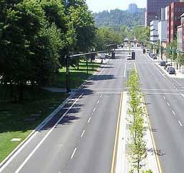
20 2.3. Bicycle Path Constructed within New Transit Corridor Design Summary Bicycle Path: 12 minimum; 17 with parallel 5 pedestrian path; 1 for signage clearance. Pavement Markings: Standard pavement markings should be used per the California MUTCD. In order to reinforce the need for separation of bicyclists and pedestrians, graphic markings may be used (as shown below). Design Example Stripping: 4 dashed yellow centerline, 4 solid white shoulder stripe, hash marks to seperate bicyclists from pedestrians, where pedestrian facilities are provided. Surfacing: Paved surface thickness adequate to support maintenance vehicles (4 min). Redwood headers if asphalt surface. Discussion High profile bikeways such as the Orange Line Bikeway require special design to meet high use by pedestrians and bicyclists allowing for separation and other amenities. Guidance California MUTCD Caltrans Highway Design Manual AASHTO Guide for the Development of Bicycle Facilities Preferred Design 20 2
21 Technical Design Handbook, 2010 Bicycle Plan 2.4. Coastal Path Design Summary Path Width: Bicycle Path: 12 minimum; 17 with parallel 5 pedestrian path, with 1 clearance for signage. Pavement Markings: Standard pavement markings should be used per the California MUTCD. In order to reinforce the need for separation of bicyclists and pedestrians, graphic markings may be used. Surfacing: Paved surface thickness 4, adequate to support maintenance vehicles. Redwood headers if asphalt surface. Discussion Coastal Paths attract many types of pathway users and conveyances. Bicyclists, pedestrians, rollerbladers, strollers, and pedicabs typically compete for space. To provide an adequate and pleasant facility, adequate widths and separation are needed to maintain a good pathway environment. Offsetting of the pedestrian path should be provided if possible. Otherwise, separation should be provided in the form of striping or landscaping. The bicycle path should be located on whichever side of the path will result in the fewest number of anticipated pedestrian crossings. For example, the bicycle path should not be placed adjacent to large numbers of destinations. Site analysis of each project is required to determine expected pedestrian behavior. Guidance California MUTCD Caltrans Highway Design Manual AASHTO Guide for the Development of Bicycle Facilities Preferred Design with separation Preferred Design no separation 2 21


22 2.5. Grade Separated Undercrossing Design Summary Width: 14 minimum to allow for access by maintenance vehicles if necessary Height: 10 minimum Pavement Markings: Standard pavement markings should be used per the California MUTCD. In order to reinforce the need for separation of bicyclists and pedestrians, graphic markings may be used. Lighting: Vandal-resistant lighting should be installed with all undercrossings in culverts or tunnels. Design Example Grade Requirements: As with other path sections, grade should not exceed 5%. Discussion See following page for discussion. Design Example Guidance Caltrans Highway Design Manual AASHTO Guide for the Development of Bicycle Facilities Minimum Design 22 2
23 Technical Design Handbook, 2010 Bicycle Plan Additional Discussion Grade Separated Undercrossing General Notes on Grade-Separated Crossings: Bicycle/pedestrian overcrossings and undercrossings provide critical bicycle path links by separating the path from conflicts with motor vehicles. These structures are designed to provide safe crossings for bicyclists where they previously did not exist. For instance, an overcrossing or undercrossing may be appropriate where bicycle demand exists to cross a freeway in a specific location, or where a flood control channel (e.g., the Los Angeles River) separates a neighborhood from a nearby bicyclist destination. These facilities may also overcome barriers posed by railroads, and are appropriate in areas where frequent or highspeed trains would create at-grade crossing safety issues, and in areas where trains frequently stop and block a desired bicycle crossing point. They may also be required by the California Public Utilities Commission which often prohibits new at-grade railroad crossings for bicyclists, or to replace existing at-grade crossings for efficiency, safety, and liability reasons. Overcrossings and undercrossings also respond to bicyclist needs where existing at-grade crossing opportunities exist but are undesirable for any number of reasons. In some cases, high vehicle speeds and heavy traffic volumes might warrant a grade-separated crossing. Hazardous bicycle crossing conditions (e.g., few or no gaps in the traffic stream, conflicts between motorists and bicyclists at intersections, etc.) could also create the need for an overcrossing or undercrossing. Undercrossing Use: Undercrossings should be considered when high volumes of bicyclists and pedestrians are expected along a corridor and: Vehicle volumes/speeds are high The roadway is wide An at-grade crossing is not feasible Crossing is needed under another grade-separated facility such as a freeway or rail line. 2 23
24 Advantages of Grade Separated Undercrossing: Improves bicycle safety while reducing delay for all users. Eliminates barriers to bicyclists. Undercrossings require 10 feet of overhead clearance from the path surface. Undercrossings often require less ramping and elevation change for the user versus an overcrossing, particularly for railroad crossings. Disadvantages/potential hazards: If the crossing is not convenient or does not serve a direct connection, it may not be well utilized. Potential issues with vandalism, maintenance. Security may be an issue if sight lines through undercrossing and approaches are inadequate. Undercrossing width greater than 14 feet, vandal resistant lighting and /or skylights are desirable for longer crossings to enhance users sense of security. High cost. 24 2

25 Technical Design Handbook, 2010 Bicycle Plan 2.6. Grade Separated Overcrossing Design Summary Width: 12 minimum width. 14 preferred. If overcrossing has any scenic vistas additional width or belvederes should be provided to allow for stopped path users. A separate 5 pedestrian area be provided for facilities anticipated to have high bicycle and pedestrian use. Design Example Height: 10 vertical clearance. Signage & Striping: 4 dashed yellow centerline, 4 solid white shoulder stripe, hash marks to seperate bicyclists from pedestrians, where pedestrian facilities are provided. Grade: Ramps should not exceed 5% grade. Discussion Overcrossings require a minimum of 17 of vertical clearance to the roadway below versus a minimum elevation differential of around 12 for an undercrossing. This results in potentially greater elevation differences and longer ramps. See following page for additional discussion. Guidance Caltrans Highway Design Manual Caltrans Bridge Design Specifications California MUTCD AASHTO Guide for the Development of Bicycle Facilities AASHTO Guide Specifications for Design of Pedestrian Bridges Preferred Design 2 25
26 Additional Discussion Grade Separated Overcrossing Ramp Considerations: Overcrossings for bicycles typically fall under the Americans with Disabilities Act (ADA), and guidance is included in the Caltrans HDM which strictly limits ramp slopes to 5% (1:20) with landings at 400 foot intervals, or 8.33% (1:12) with landings every 30 feet. Overcrossing Use: Overcrossings should be considered when high volumes of bicycles are expected along a corridor and: Vehicle volumes/speeds are high. The roadway to be crossed consists of multiple travel lanes. An at-grade crossing is not feasible. Crossing is needed over a grade-separated facility such as a freeway or rail line. Advantages of Grade Separated Overcrossing: Improves bicycle safety while reducing delay for all users. Eliminates barriers to bicyclists. Disadvantages / Potential Hazards: If the crossing is not convenient or does not serve a direct connection, it may not be well utilized. Overcrossings require at least 17 feet of clearance to the roadway below involving up to 400 feet or greater of approach ramps at each end. Long ramps must meet ADA requirements. Potential issues with vandalism, maintenance. High cost. 26 2
27 Technical Design Handbook, 2010 Bicycle Plan 2.7. Fencing Design Summary Height: 5 minimum Discussion Fencing can serve multiple purposes along bicycle path facilities, including access control, visual screening, channeling of path users, and safety. Design Example See right column and following page for discussion: Guidance Caltrans Highway Design Manual AASHTO Guide for the Development of Bicycle Facilities General Notes on Fencing: Some factors to consider when deciding on fencing necessity and styles include: Cost: Fencing and other barriers, depending on the type of materials used and the length, can be costly, so options should be considered carefully. Security: Fencing between the path and adjacent land uses can protect the privacy and security of the property owners. While crime or vandalism has not been proven to be a common problem along most bicycle paths, fencing is still considered a prudent feature. The type, height, and responsibility of the fencing is dependent on local conditions. Fencing height: The height and design of a fence influences whether lateral movement will be inhibited. Few fences are successful at preventing people from continuing to cross at historic illegal crossing locations. Fencing that cannot be climbed will typically be cut or otherwise vandalized. Heavy-duty fencing such as wrought iron or steel mesh security fencing that are difficult to climb are often much more expensive. Noise and dust: Bicycle path corridors adjacent to busy roadways, freeways or rail lines may be subject to noise, dust, vibration or vandalism, which may discourage use of the path. Methods of reducing this impact include the addition of vegetation or baffles to fencing barriers. This can increase the initial cost and ongoing maintenance cost. Fence types: The following page illustrates common types of fencing typically used with bicycle paths. 2 27
28 Additional Discussion Fencing 28 2
29 0
30 0
 are defined as a portion of the roadway that has been designated by striping, signage, and pavement")
31 Technical Design Handbook, 2010 Bicycle Plan Section 3. Design of Bicycle Lanes Bicycle lanes or Class II bicycle facilities (Caltrans designation) are defined as a portion of the roadway that has been designated by striping, signage, and pavement markings for the preferential or exclusive use of bicyclists. Bicycle lanes are generally found on major arterial and collector roadways in Los Angeles and are 5-7 feet wide. Bicycle lanes can be found in a large variety of configurations. Bicycle lanes provide bicyclists with their own space on the roadway and enable them to ride at their preferred speed without interference from prevailing traffic conditions. Bicycle lanes facilitate predictable behavior and movements between bicyclists and motorists. Bicyclists may leave the bicycle lane to pass other bicyclists, make left turns, avoid obstacles or debris, merge with traffic at intersections, and to avoid conflicts with other roadway users. General Design Guidance: Width: Varies depending on roadway configuration; see following pages for design examples. Striping: Line separating vehicle lane from bicycle lane: 6 inches Line separating bicycle lane from parking lane: 4 inches Dashed white stripe when: Vehicle merging area (approximately 50 feet to 200 feet). Delineate conflict area in intersections (optional) Length of conflict area. 3 31
32 Signing: Use R81 (CA) Bicycle Lane Sign at: Beginning of Bicycle Lane At approaches and at far side of all arterial crossings At major changes in direction At intervals not to exceed ½ mile Pavement Markings: Pavement markings for bicycle lanes shall be the BIKE LANE stencil or graphic representation of a bicyclist with directional arrow (preferred) to be used at: R81 (CA) Sign Beginning of bicycle lane Far side of all bicycle path (Class I) crossings At approaches and at far side of all arterial crossings At major changes in direction At intervals not to exceed ½ mile At beginning and end of bicycle lane pockets at approach to intersection. Figure Approved Bike Lane Stencils 32 3
33 Technical Design Handbook, 2010 Bicycle Plan 3.1. Bicycle Lane Next to On-Street Parallel Parking Design Summary Bicycle Lane Width: 5 minimum, 7 maximum recommended when parking stalls are marked. 12 minimum (14 preferred) for a shared bicycle/parking lane adjacent to a curb face, or 11 minimum where parking is permitted but not marked on streets without curbs. Design Example Discussion Bicycle lanes adjacent to on-street parallel parking are common in the United States. Crashes caused by a suddenly opened vehicle door are a hazard for bicyclists using this type of facility. Providing wider bicycle lanes is one way mitigate against potential bicyclist collisions with car doors. However, if the outer edge of the bicycle lane abuts the parking stall, bicyclists may still ride too close to parked cars. Bicycle lanes that are too wide may also encourage vehicles to use the bicycle lane as a loading zone in busy areas where on-street parking is typically full or motorists may try to drive in them. Encouraging bicyclists to ride farther away from parked vehicles will increase the safety of the facility. Preferred Design (if space is available) Preferred Minimum Design
34 If sufficient space is available, the preferred design provides a buffer zone between parked cars and the bicycle lane. This could be accomplished by using parking T s to increase separation; in Los Angeles, parking T s are typically installed adjacent to metered parking. Guidance California MUTCD Caltrans Highway Design Manual AASHTO Guide for the Development of Bicycle Facilities Additional Discussion - Bicycle Lane Next to On-Street Parallel Parking From the Caltrans Highway Design Manual: The figure below depicts bicycle lanes on an urban type curbed street where parking stalls (or continuous parking stripes) are marked. Bicycle lanes are located between the parking area and the traffic lanes. As indicated, 5 feet shall be the minimum width of bicycle lane where parking stalls are marked. If parking volume is substantial or turnover high, an additional one to two feet of width is desirable. Bicycle lanes shall not be placed between the parking area and the curb. Such facilities increase the conflict between bicyclists and opening car doors and reduce visibility at intersections. Also, they prevent bicyclists from leaving the bicycle lane to turn left and cannot be effectively maintained. The figure below depicts bicycle lanes on an urban-type curbed street, where parking is permitted, but without parking stripe or stall marking. Bicycle lanes are established in conjunction with the parking areas. As indicated, 11 or 12 feet (depending on the type of curb) shall be the minimum width of the bicycle lane where parking is permitted. This type of lane is satisfactory where parking is not extensive and where turnover of parked cars is infrequent. However, if parking is substantial, turnover of parked cars is high, truck traffic is substantial, or if vehicle speeds exceed 55 km/h, additional width is recommended. 34 3
35 Technical Design Handbook, 2010 Bicycle Plan From AASHTO Guide for the Development of Bicycle Facilities (1999): If parking is permitted, the bicycle lane should be placed between the parking area and the travel lane and have a minimum width of 5feet. Where parking is permitted but a parking stripe or stalls are not utilized, the shared area should be a minimum of 11 feet without a curb face and 12 feet adjacent to a curb face as shown in figure below. If the parking volume is substantial or turnover is high, an additional 1 to 2 feet of width is desirable. 3 35
 where a wider bicycle lane can")
36 3.2. Bicycle Lane with No On-Street Parking Design Summary Bicycle Lane Width: 5 minimum measured from face of curb when adjacent to curb Preferred Width: 6-7 where right-of-way allows Maximum Width: 7 adjacent to arterials with high travel speeds Discussion Wider bicycle lanes are desirable in certain circumstances such as on higher speed arterials (45 mph+) where a wider bicycle lane can increase separation between passing vehicles, parked vehicles and bicyclists. Wide bicycle lanes are also appropriate in areas with high bicycle use. A bicycle lane width of 6 to 7 feet makes it possible for bicyclists to pass each other without leaving the bicycle lane, increasing the capacity of the bicycle lane. Frequent signing and pavement markings are important with wide bicycle lanes to ensure motorists do not mistake the lane for a vehicle lane or parking lane. Guidance California MUTCD Caltrans Highway Design Manual AASHTO Guide for the Development of Bicycle Facilities Design Example Preferred Design 36 3

37 Technical Design Handbook, 2010 Bicycle Plan 3.3. Bicycle Lane on Left Side of One-Way Street Design Summary Bicycle Lane Width: 5 minimum when adjacent to curb and gutter 7 maximum See guidance on Bicycle Lanes Next to On-Street Parallel Parking Design Example Preferred Design Discussion Bicycle Lanes on the left side of a one-way street are generally discouraged, but they can be useful in certain limited circumstances. See following page for further discussion: Guidance Caltrans Highway Design Manual Expanded coverage in the draft 2009 AASHTO Guide For the Development of Bicycle Facilities AASHTO Guide for the Development of Bicycle Facilities 3 37
38 Additional Discussion - Bicycle Lane on Left Side of One- Way Street Left-side bicycle lanes one one-way streets should only be considered on roadways with either: Heavy transit use on the right side of the street (either in a dedicated lane or with traffic). High volumes of right turn movements by vehicles. Bicyclists need to make left turns on the one way street. Advantages of a left side bicycle lane on a one-way street: Increased driver visibility with the bicycle lane on the left, bicyclists are seen in the motorist s driver s side mirror, which has a smaller blind spot than the passenger side mirror. Fewer bus and truck conflicts Most bus stops and loading zones are on the right side of the street. Left-side bicycle lanes reduce the number of conflicts caused by buses or trucks blocking or merging through a bicycle lane. Disadvantages / potential hazards: Potential for increased conflicts between bicyclists and motorists making left turns. A left turn pocket with the bicycle lane oriented to the right may address these conflicts if space permits. See section for example, configuration would be reversed in this case. Drivers are not used to looking for bicycles on the left hand side of their vehicles. Car passengers opening doors are less likely to be aware of the presence of bicyclists to their right. Bicycle lanes on the left side of the street may experience higher levels of wrong way riding by bicyclists. Bicyclists may not be accustomed to looking over their right shoulders to monitor traffic, helmet and handlebar mounted mirrors are also useless. Where adjacent to parallel parking, left side bicycle lanes may result in poorer visibility to motorists leaving parking spaces. 38 3

39 Technical Design Handbook, 2010 Bicycle Plan 3.4. Shared Bicycle-Bus Lane Design Summary Design Example Example Signage Bicycle Lane Width: Preferred width from curb to outside edge of lane is 16 feet. This width allows comfortable passing of bicyclists. Fourteen feet (14 ) may be allowed on roadways with low traffic volumes and/or lower bus frequency. Twelve feet (12 ) should only be considered in very constrained areas. Signage: There is no current standard CA MUTCD or MUTCD signage for a shared bicycle-bus lane. Many cities have developed their own signage. The City of Los Angeles uses the signage and stencils shown in the photographs below. Discussion Typically situated adjacent to the curb, combined bicycle-bus lanes are used where sufficient width exists for a bus lane, but not for separated bus and bicycle lanes. Bylaw, California bicyclists must ride as far to the right as practicable. This allows bicyclists lawful use of a right-hand bus lane. Generally, such multiple uses are operationally acceptable unless very high volumes of bus and bicycle traffic exist. See following page for additional discussion: Guidance No explicit guidance in existing State or Federal manuals. Preferred Design 3 39
40 Additional Discussion - Shared Bicycle-Bus Lane Shared bicycle-bus lanes should be considered when: High frequency bus routes overlap highly used bicycle routes. Adequate right-of-way exists to accommodate the facility; travel lane narrowing may be an option. Vehicular right turns are limited or prohibited. Advantages of shared bicycle-bus lanes: Professional bus drivers should be well trained to operate conservatively around bicyclists. Minimizes interaction between bicyclists and non-bus motor vehicles. Disadvantages / potential hazards: Right turning vehicles can reduce benefits of facility. If bus lane is not well utilized, private vehicles may use the lane or be encouraged to speed. Some bicyclists may be uncomfortable with buses passing closely. Bicyclists will experience leap frog effect between bicycles and buses where buses pass bicycles between stops and bicycles pass buses at stops. 40 3

41 Technical Design Handbook, 2010 Bicycle Plan 3.5. Dedicated Bicycle Lane with Bus Lane Design Summary Bicycle Lane Width: 5 minimum, 7 maximum. Combined Facility Width: Design Example Minimum width from curb to outside edge of bicycle lane is 18 feet. Discussion Typically situated adjacent to the curb, dedicated bicycle lane/ bus lanes are used where sufficient width exists for a bus lane, and a separated bicycle lane. On one-way streets with bus lanes, a bicycle lane on the left side of the street should also be considered. See following page for additional discussion: Guidance No explicit guidance in existing State or Federal guidance. Preferred Design 3 41
42 Additional Discussion - Dedicated Bicycle Lane with Bus Lane Dedicated bicycle lane with bus lane should be considered when: Adequate right-of way exists to accommodate the facility. Travel lane narrowing may be an option. High frequency bus routes overlap high use bicycle routes. Vehicular right turns can be limited or prohibited. Advantages of dedicated bicycle lane with bus lane Provides an improved location for a bicycle lane as bicyclists must pass a bus on the left even if a bicycle lane is not present. Decreases bicycle and bus conflict. Avoids leap frog effect between bicycles and buses where buses pass bicycles between stops and bicycles pass buses at stops. Disadvantages / potential hazards Right turning vehicles can reduce benefits of facility. If bus lane is not well utilized, private vehicles may use the lane or be encouraged to speed. Some bicyclists may be uncomfortable with traffic passing them on two sides if installed between bus lane and parallel travel lanes. 42 3
.")
43 Technical Design Handbook, 2010 Bicycle Plan 3.6. Uphill Climbing Bicycle Lanes Design Summary Bicycle Lane Width: Uphill bicycle lane should be 5 or 6 feet wide (6 is preferred for extra maneuvering room on steep grades). Design Example Striping: On the uphill side, use a 6 stripe between the vehicle travel lane and bike lane, and a 4 stripe between the bicycle lane and the parking lane or shoulder. On the downhill side, use a 4 shoulder stripe or edgeline between vehicle travel lane and the parking lane shoulder. Discussion While descending bicyclists are often able to maintain vehicular travel speeds. Bicyclists ascending hills tend to lose momentum, especially on longer street segments with continuous uphill grades. This speed reduction creates greater speed differentials between bicyclists and motorists, creating uncomfortable and potentially unsafe riding conditions. Separating vehicle and bicycle traffic, uphill bicycle lanes (also known as climbing lanes ) enable motorists to safely pass slower-speed bicyclists, thereby improving conditions for both travel modes. The right-of-way or curb-tocurb width on some streets may only provide enough space to stripe a bicycle lane on one side. Under these conditions, bicycle lane striping could be added to the uphill side of the street. This measure often includes delineating on-street parking (if provided), slightly narrowing travel lanes, and/or shifting the centerline if necessary. The measure is currently used in Portland, Oregon; San Francisco, Seattle, Washington, and Madison, Wisconsin. Guidance California MUTCD Caltrans Highway Design Manual Facility combines guidance for Shared Lane Marking and Class II bicycle lane. 3 43
44 Preferred Design 44 3

45 Technical Design Handbook, 2010 Bicycle Plan 3.7. Bicycle Lanes at Channelized Intersection with Right Turn Pocket Design Summary Bicycle Lane Width: Bicycle Lane pocket, next to a right turn pocket, should be 4 minimum in width; 5 preferred. Design Example Striping: Use a 6 stripe between the vehicle through lane and bike lane, and a 4 stripe between the bicycle lane and the right turn lane. Discussion According to the CA MUTCD and Highway Design Manual, the appropriate treatment for right-turn only lanes is to place a bicycle lane pocket between the right-turn lane and the right-most through lane or, where right-of-way is insufficient, to drop the bicycle lane entirely approaching the right-turn lane. The design (right) illustrates a bicycle lane pocket, with signage indicating that motorists should yield to bicyclists through the merge area. While the CA MUTCD states that the dashed lines in the merging area are optional, it is recommended that they be an integral part of any intersection with this treatment in Los Angeles. The merge area (dashed lines) should begin no less than 50 before the stop line on the near side of the intersection. Dropping the bicycle lane should only be done when a bicycle lane pocket cannot be accommodated. Travel lane reductions may be required to achieve this design. Guidance California MUTCD Caltrans Highway Design Manual AASHTO Guide for the Development of Bicycle Facilities Preferred Design 3 45


46 3.8. Bicycle Lanes at Double Right Turn Intersections Design Summary Width: Bicycle Lane pocket should have a minimum width of 4 with 5 preferred. Discussion Design Example Merging across two lanes exceeds the comfort zone of most bicyclists. Double right turn lanes or an inside through/right combination lane should be avoided on routes with heavy bicycle use. To prevent vehicles in the outside right turn lane from turning into a bicyclist it is important to encourage proper lane positioning for the bicyclist. This can be accomplished by providing either a bicycle lane to the left of the outside turn lane with a bicycle lane (Option A). This design positions bicyclists using a bicycle lane to the outside of a double right-turn lane. This treatment should only be considered at locations where the right most turn lane is a pocket at the intersection. In this instance, the bicyclist would only have to merge across one lane of traffic to reach the bicycle lane. While non-standard colored bicycle lanes may also help distinguish the bicycle lane in the merging area. Bicyclist should not be expected to merge across two lanes of traffic to continue straight though an intersection. Guidance California MUTCD Preferred Design Option A Bicycle Lane 46 3
47 Technical Design Handbook, 2010 Bicycle Plan Additional Discussion - Bicycle Lanes at Double Right Turn Intersections The use of double-turn lanes should be discouraged because of the difficulties they present for pedestrians and bicyclists. Existing double-turn lanes should be studied and converted to singleturn lanes, unless found to be absolutely necessary for traffic operations. In situations where the double-turn lane cannot be avoided, the options on the previous page can be used to better accommodate bicyclists. Advantages of Bicycle Treatments at Double Right Turn Lanes: Aids in correct positioning of bicyclists at intersections with a double right turn lanes. Bicyclists should be able to travel straight through an intersection without vehicles turning through their path. Encourages motorists to yield to bicyclists when using the outside right turn lane. Reduces motor vehicle speed within the right turn lanes. Disadvantages / potential hazards: Many bicyclists may be uncomfortable with double right turn lanes regardless of the treatment. Not suitable for intersections with high bicycle volumes the second right turn lane should be eliminated in such cases. to yield to bicyclists when using the outside right turn lane. Reduces motor vehicle speed within the right turn lanes. Disadvantages / potential hazards: Many bicyclists may be uncomfortable with double right turn lanes regardless of the treatment. Not suitable for intersections with high bicycle volumes the second right turn lane should be eliminated in such cases. 3 47
48 0

49 Technical Design Handbook, 2010 Bicycle Plan Section 4. Design of Bicycle Routes (Class III) Class III bicycle facilities (Caltrans designation) are defined as facilities shared with motor vehicles. They are typically used on roads with low speeds and traffic volumes, however they can be used on higher volume roads with wide outside lanes or with shoulders. A motor vehicle driver will usually have to cross over into the adjacent travel lane to pass a bicyclist, unless a wide outside lane or shoulder is provided. From the Caltrans Highway Design Manual: Class III bikeways (bicycle routes) are intended to provide continuity to the bikeway system. Bicycle routes are established along through routes not served by Class I or II bikeways, or to connect discontinuous segments of bikeway (normally bicycle lanes). Class III facilities are shared facilities, either with motor vehicles on the street, or with pedestrians on sidewalks, and in either case bicycle usage is secondary. Class III facilities are established by placing Bicycle Route signs along roadways. Bicycle Routes can employ a large variety of treatments from simple signage to complex treatments including various types of traffic calming and/or pavement stenciling. The level of treatment to be provided for a specific location or corridor depends on several factors. D11-1 Sign General Design Guidance: Width: Varies depending on roadway configuration; see following pages for design examples. Striping: If shoulder is present, a 4-inch edge line separating vehicle lane from shoulder for bicycle use should be used. Signing: Use D11-1 Bicycle Route Sign at: Beginning or end of Bicycle Route (with applicable M4 series sign below) Entrance to bicycle path (Class I) - optional At major changes in direction or at intersections with other bicycle routes (with applicable M7 series sign below) At intervals along bicycle routes not to exceed ½ mile Pavement Markings: Shared Lane Markings (SLM) may be applied to Bicycle Routes per the CA MUTCD requirements. 4 49
50 4.1. Bicycle Route with Wide Outside Lane Design Summary Bicycle Lane Width: Fourteen feet (14 ) minimum shared travel lane is preferred. Fifteen feet (15 ) should be considered if heavy truck or bus traffic is present. Bicycle lanes should be considered on roadways with outside lanes wider than 15 feet. This treatment is found on residential streets, collectors, and minor arterials Discussion This is a common existing facility found in many areas in Los Angeles. The wide outside lane provides adequate on-street space for the vehicle and bicycle to share the lane without requiring the vehicle to leave its lane to pass the bicyclist. This facility is frequently found with and without on-street parking. Guidance California MUTCD Caltrans Highway Design Manual AASHTO Guide for the Development of Bicycle Facilities Design Example Preferred Design 50 4
51 Technical Design Handbook, 2010 Bicycle Plan 4.2. Bicycle Route on Collector/Residential Street Design Summary Sign Placement: Bicycle Route signage should be applied at intervals frequent enough to keep bicyclists informed of changes in route direction and to remind motorists of the presence of bicyclists. Discussion Design Example Preferred Design Bicycle routes on local streets should have vehicle traffic volumes under 1,000 vehicles per day. Traffic calming may be appropriate on streets that exceed this limit. Bicycle routes may be equipped with directional signage, traffic diverters, chicanes, chokers, and /or other traffic calming devices to reduce vehicle speeds or volumes. Such treatments often are associated with Bicycle Friendly Streets (see Section for discussion of Bicycle Friendly Streets). Guidance California MUTCD Caltrans Highway Design Manual AASHTO Guide for the Development of Bicycle Facilities 4 51

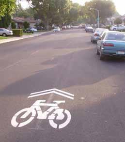
52 4.3. Shared Lane Marking (SLM) Design Summary Door Zone Width: The width of the door zone is generally assumed to be 2.5 feet from the edge of the parking lane. Recommended SLM placement: Minimum of 11 feet from edge of curb where on-street parking is present but may be placed more than 11 feet as conditions support. If parking lane is wider than 7 the SLM should be moved further out accordingly. Discussion Shared Lane Marking stencils (commonly called Sharrows ) have been introduced for use in California and may be used as an additional treatment for Class III facilities but are currently only allowed for use in conjunction with on-street parking. The stencil can serve a number of purposes, such as reminding bicyclists to ride further from parked cars to prevent dooring collisions, making motorists aware of bicycles potentially in the travel lane, and showing bicyclists the correct direction of travel. The paving marking was adopted for official use by Caltrans in the 2003 California MUTCD. The 11 minimum distance from curb shown in the CA MUTCD is based on a 7 parking stall. Shared lane markings adjacent to an 8 parking stall may be installed at a minimum of 12 from centerline to curb. Placing the SLM between vehicle tire tracks (meeting CA MUTCD guidance) may also be considered as it will increase the life of the markings and the long-term cost of maintenance to the treatment. Guidance California MUTCD Design Example Minimum Design 52 4
53 Technical Design Handbook, 2010 Bicycle Plan 4.4. Bicycle Friendly Street (BFS) Design Summary Bicycle Friendly Streets (BFS) generally are installed on minor or local roadways. No design standard exists. See following pages for additional guidance. Design Elements of a Bicycle Friendly Street Design Example 4 53
54 Discussion On Bicycle Friendly Streets, or Bicycle Routes, it is important to provide a benefit to the bicyclist who chooses the route. Frequently this benefit is composed of reduced travel time, lower motor vehicle traffic volumes and/or reduced motor vehicle speeds. Ideally, bicyclists should not be required to make frequent stops. The Bicycle Friendly Street or bicycle route should be watched closely following treatment to determine if there is an increase in vehicle trips along the bicycle route as many motorists may take advantage of fewer stops thereby reducing the effectiveness of the facility for bicycles. If motor vehicle ADT increases, treatments may be considered such as diagonal diverters, one-way closures, chicanes, chokers and other applicable treatments to preserve bicycle permeability and limit through vehicle access. See following pages for additional discussion. Guidance No explicit guidance in State or Federal manuals Additional Discussion - Bicycle Friendly Streets (BFS) This section describes various treatments commonly used for developing Bicycle Friendly Streets. The treatments fall within five main application levels based on their level of physical intensity, with Level 1 representing the least physically-intensive treatments that could be implemented at relatively low impact on roadways that already function well for bicyclists. Identifying appropriate application levels for individual Bicycle Friendly Street corridors provides a starting point for selecting appropriate sitespecific improvements. The five Bicycle Friendly Street application levels include the following: Level 1: Signage See Section 4.4. Level 2: Pavement markings See Section 4.4. Level 3: Intersection treatments See Sections Level 4: Traffic calming See Sections 4.5 and 4.7. Level 5: Traffic diversion See Sections
55 Technical Design Handbook, 2010 Bicycle Plan It should be noted that corridors targeted for higher-level applications would also receive relevant lower-level treatments (as illustrated below). For instance, a street targeted for Level 3 applications should also include Level 1 and 2 applications as necessary. It should also be noted that some applications may be appropriate on some streets while inappropriate on others. In other words, it may not be appropriate or necessary to implement all Level 2 applications on a Level 2 street. Furthermore, several treatments could fall within multiple categories as they achieve multiple goals. To identify and develop specific treatments for each Bicycle Friendly Street, the City should involve the bicycling community and neighborhood groups. Further analysis and engineering design work may also be necessary to determine the feasibility of some applications. 4 55
56 4.5. Bicycle Route/BFS Signing & Pavement Markings Design Summary Design varies; see following page for additional discussion. Discussion Bikeway signage is a cost-effective yet highly-visible treatment that can improve the riding environment on a Bicycle Friendly Street network. Described in this section, signage can serve both wayfinding and safety purposes. See following page for additional discussion: Guidance California MUTCD Caltrans Highway Design Manual AASHTO Guide for the Development of Bicycle Facilities Chicago s Bikeways Signage System - org/2006conference/vconference/presentations/ GrantDavisChicagosBikewaysSignageSystem.pdf Design Example Potential Signage/Wayfinding Options 56 4
57 Technical Design Handbook, 2010 Bicycle Plan Additional Discussion - Bicycle Route/BFS Signing & Pavement Markings Signage Wayfinding Signs: Shown on previous page, wayfinding signs are typically placed at key locations leading to and along Bicycle Friendly Streets, including where multiple routes intersect and at key bicyclist decision points. Wayfinding signs displaying destinations and distances can dispel common misperceptions about time and distance while increasing user ease and accessibility to the BFS network. Wayfinding signs also visually cue motorists that they are driving along a bicycle route and should correspondingly use caution. Note that too many road signs tend to clutter the rightof-way and become invisible to regular users. Warning signs: Warning signs advising motorists to Share the Road may also improve bicycling conditions on a Bicycle Friendly Street network. These signs may be useful near major bicycle trip generators such as schools, parks and other activity centers. Warning signs should also be placed on major streets approaching Bicycle Friendly Streets to alert motorists of bicycle crossings. Pavement Markings Pavement marking techniques may also improve bicycling conditions along a Bicycle Friendly Street network which may include shared lane markings and loop detector markings. Shared Lane Markings: Shared Lane Marking (SLM See Section 5.5.3) are often used on streets where dedicated bicycle lanes are desirable but not possible due to physical or other constraints. They also may be used as Bicycle Friendly Street markings where on street parking is present. 4 57
58 On-Street Parking Delineation: Delineating on-street parking spaces with parking Ts clearly indicates where a vehicle should be parked, and can discourage motorists from parking their vehicles too far into the adjacent travel lane. This helps bicyclists by maintaining a wide enough space to safely share a travel lane with moving vehicles while minimizing the need to swerve farther into the travel lane to maneuver around parked cars and opening doors. In addition to benefiting bicyclists, delineated parking spaces also promote the efficient use of on-street parking by maximizing the number of spaces in high-demand areas. Loop Detector Stencils: At signalized intersections with in-pavement detection, the CA MUTCD Bicycle Detector Symbol may be used to indicate where bicyclists should wait to activate a green light. (See section 5.7.2) 58 4

59 Technical Design Handbook, 2010 Bicycle Plan 4.6. Bicycle Route/BFS at Local Intersections Mini- Roundabout Design Summary Design varies; see below and following pages for additional discussion. Discussion Design Example Mini Roundabout Roundabouts can be effective in several scenarios when used along a Bicycle Friendly Street and cross-streets. Typically mini-roundabouts are implemented where the Bicycle Friendly Street intersects a local street or even a collector if the ADT is less than 2,000. Signage and striping treatments should be implemented based on traffic volumes and may be appropriate for local/local intersections with very low ADT, while increased signage and splitter striping may be appropriate for larger ADTs and intersections with collector streets. Mini-roundabouts can be landscaped with drought tolerant plants that do not impact sight lines for added visual impact and traffic calming effect. Treatment should be designed with the input of LAPD and LAFD for emergency vehicle access. Advantages: Very effective at reducing through bicycle and cross vehicle conflicts. Adds overall traffic calming in all directions. Use where unwarranted stop signs exist. Disadvantages: Moderate cost (approx $20,000 per intersection). Required approval of neighborhood for installation. Required neighborhood support and adoption for maintenance of landscaping if installed. Guidance California MUTCD Caltrans Highway Design Manual FHWA Roundabouts: An Informational Guide AASHTO Guide for the Development of Bicycle Facilities Berkeley Bicycle Boulevard Design Tools and Guidelines 4 59
60 4.7. Bicycle Route/BFS at Local Intersections Stop Signs on Cross-Streets Design Summary Design varies; see below and following pages for additional discussion. Discussion The installation of a stop sign on cross streets along the Bicycle Friendly Street or Bicycle Route maximizes through bicycle connectivity and speed and requires motorists crossing the facility to stop and proceed when safe. This treatment will typically be unwarranted and should be considered a traffic calming tool rather than a traffic control device. Advantages: Inexpensive installation. Effective at reducing though bicycle and cross vehicle conflicts. Disadvantages: May be unwarranted as traffic control device. Guidance California MUTCD Caltrans Highway Design Manual AASHTO Guide for the Development of Bicycle Facilities Berkeley Bicycle Boulevard Design Tools and Guidelines webserver.ci.berkeley.ca.us/uploadedfiles/public_works/ Level_3_-_General/ch4_.pdf Stop Signs on Cross Streets Design Example 60 4
61 Technical Design Handbook, 2010 Bicycle Plan 4.8. Bicycle Route/BFS at Local Intersections Curb Bulbouts and High-Visibility Crosswalks Design Summary Design varies; see below and following pages for additional discussion. Discussion This treatment is appropriate for Bicycle Friendly Streets or Bicycle Routes near activity centers that may generate large amounts of pedestrian activity such as schools or commercial areas. The bulbouts should only extend across the parking lane and should not obstruct bicyclists path of travel or the travel lane. This treatment may be combined with a stop sign on the cross street if necessary. Advantages: Traffic calming device. Disadvantages: May impact on-street parking. Moderate cost (approx $5,000-$15,000 per intersection). May impact bus/truck turning movements. May impact emergency vehicles. Issues with storm water drains and runoff. Guidance AASHTO Guide for the Development of Pedestrian Facilities Berkeley Bicycle Boulevard Design Tools and Guidelines webserver.ci.berkeley.ca.us/uploadedfiles/public_works/ Level_3_-_General/ch4_.pdf Curb Bulbouts and High- Visibility Crosswalks Design Example 4 61
62 4.9. Bicycle Route/BFS at Local Intersections Diagonal Diverter Design Summary Design varies; see below and previous pages for additional discussion. Discussion This treatment prevents through vehicle traffic and is appropriate for Bicycle Friendly Streets or Bicycle Routes where through vehicle traffic may be high or is not desired. The diverter should be designed so that emergency vehicles may still permeate the diverter with a minimum of delay, potentially using flexible bollards. The diverter may landscaped with drought tolerant plants that do not impact sight lines to enhance the greenspace of the neighborhood. Advantages: Traffic calming device. Reduces through vehicle movements along BFS. Disadvantages: May slightly slow emergency responders. Moderate cost (approx $4,000-$10,000 per intersection). May impact street maintenance and, if landscaped, should be adopted by neighborhood for landscape maintenance. Guidance Berkeley Bicycle Boulevard Design Tools and Guidelines webserver.ci.berkeley.ca.us/uploadedfiles/public_works/ Level_3_-_General/ch4_.pdf Diagonal Diverter Design Example 62 4
63 Technical Design Handbook, 2010 Bicycle Plan Bicycle Route/BFS at Local/Major Signalized Intersections Design Summary Design varies; see following page for additional discussion. Discussion Bicyclists must be detected at signalized intersections for the Bicycle Friendly Street to be effective. The photo below depicts an intersection of a Bicycle Friendly Street with a major street. Through motor vehicle traffic is prohibited while bicycle through traffic is controlled with a dedicated through lane with embedded loop detection. See adjacent column for additional discussion: Design Example Guidance California MUTCD Caltrans Highway Design Manual AASHTO Guide for the Development of Bicycle Facilities Special Considerations for Bicyclists at Local/Major Signalized Intersections For a signalized intersection to function properly for a bicyclist crossing a major roadway at a signalized intersection, the following considerations must be addressed: Easy and accurate detection by the traffic signal controller by one of the following: - An embedded loop with placement and sensitivity to detect a bicycle. Identify loop with the standard Bicycle Detector Symbol shown in Figure 9C-7(CA) in the California MUTCD. - Video detection technology. - Use of a bicyclist-activated push button, as long as they do not require bicyclists to dismount or make unsafe leaning movements. These devices should be placed as close to the street as possible in a location that is unobstructed by parked vehicles or motorists making right-hand turns. Safe location to wait for green signal Bicyclists awaiting a green light should not block vehicle right turns (if allowed). Sufficient lane width or stenciling can help with lane positioning and traffic flow. Signal timing providing adequate time for bicyclists to safely cross the intersection. In situations where there are few crossable gaps and where vehicles on the major street do not stop for pedestrians and bicyclists waiting to cross, half signals, that stop traffic only along one of the streets could be installed to improve the crossing environment. Half signals include bicycle activation buttons and may also include bicycle loop detectors on the Bicycle Friendly Street approach. Many of these models have been used successfully for years overseas, and their use in the U.S. has increased dramatically over the last decade. 4 63

64 4.11. Bicycle Route/BFS at Local/Major Unsignalized Intersections Crossing Islands Design Summary Various designs are applicable for crossing islands. Designs vary: see following page for additional discussion. Discussion Bicycle crossing islands enable crossing for bicyclists where traffic signals or other designs may not be feasible. Guidance Caltrans Highway Design Manual California MUTCD AASHTO Guide for the Development of Bicycle Facilities Design Example Recommended Design (not to scale) 64 4
65 Technical Design Handbook, 2010 Bicycle Plan Additional Discussion - Bicycle Route/BFS at Local/ Major Unsignalized Intersections Crossing Islands Special Considerations for Bicyclists at Local/Major Unsignalized Intersections: At intersections of Bicycle Friendly Streets/bicycle routes and major unsignalized intersections, a bicycle crossing island should be provided to allow bicyclists to cross one direction of traffic at a time when gaps in traffic allow. The bicycle crossing island should be at least 8 feet wide (measured perpendicular to the centerline of the major road) to be used as a bicycle refuge. Narrower medians can accommodate bikes if the holding area is at an acute angle to the major roadway, which allows stopped bicyclists to face oncoming motorists. Crossing islands should be in the middle of the intersection, thus prohibiting left and through vehicle movements or at the sides in conjunction with a high-visibility crosswalk (left turn prohibition is recommended). Advantages of bicycle crossing islands: Provides safe refuge in the median of the major street so that bicyclists only have to cross one direction of traffic at a time works well with signal controlled traffic platoons coming from opposite directions. Provides traffic calming and safety benefits by preventing left turns and/or through traffic from using the intersection. Disadvantages / potential hazards: Potential impacts to major roadway, including lane narrowing, loss of some on-street parking and restricted turning movements. Crossing island may collect debris and may be difficult to maintain. 4 65
66 0

67 Technical Design Handbook, 2010 Bicycle Plan Section 5. Gap Closures & Roadway Retrofits This Chapter describes the recommended procedure for addressing connection gaps in the Los Angeles bikeway network. The appropriate gap closure measure type depends on both the bikeway gap type and location. Most arterial streets in Los Angeles are characterized by conditions (e.g., high vehicle speeds and/or volumes) for which dedicated bicycle lanes are appropriate to accommodate safe and comfortable riding. Indicating a preferential or exclusive space for bicycle travel, bicycle lanes are typically five to six feet wide with delineation taking the form of striping and pavement markings. These facilities create a predictable environment for motorists and bicyclists by clarifying the appropriate position for each user on a roadway. Bicycle lanes on congested streets also enable bicyclists to pass slow or stopped vehicles on the right. Some of the measures in this chapter represent various approaches for adding bicycle lanes to existing streets. Although opportunities to add bicycle lanes through roadway widening may exist in some locations, most major Los Angeles streets pose physical and other constraints requiring street retrofit measures within existing curb-to-curb widths. As a result, the measures in this section effectively reallocate existing street width through striping modifications to accommodate dedicated bicycle lanes. Sections discusses options for the accommodation of bicyclists where a bicycle lane cannot be provided through the methods described in the following pages. The bicycle lane retrofit measures described below are most appropriate for addressing connection gaps and linear gaps, though they could supplement other measures to address corridor and system gaps. Although largely intended for arterial streets, these measures may be appropriate on some collector streets where bicycle lanes would best accommodate bicyclists. 5 67
68 The following typologies have been developed to categorize gaps in a bikeway network: Connection gaps: Connection gaps are missing segments (1/4 mile long or less) on a clearly defined and otherwise well-connected bikeway. Major barriers standing between bicycle destinations and clearly defined routes also represent connection gaps. Examples include bicycle lanes on a major street dropping for several blocks to make way for on-street parking; a discontinuous off-street path; or a freeway standing between a major bicycle route and a school. Linear Gaps: Similar to connection gaps, linear gaps are ½- to one-mile long missing link segments on a clearly defined and otherwise well-connected bikeway. Corridor Gaps: On clearly defined and otherwise well-connected bikeways, corridor gaps are missing links longer than one mile. These gaps will sometimes encompass an entire street corridor where bicycle facilities are desired but do not currently exist. System Gaps: Larger geographic areas (e.g., a neighborhood or business district) where few or no bikeways exist would be are identified as system gaps. System Gaps exist in areas where a minimum of two intersecting bikeways would be required to achieve the target network density. 68 5
 Discussion Design Example Preferred Design Lane narrowing utilizes roadway space that exceeds minimum standards to create the")
69 Technical Design Handbook, 2010 Bicycle Plan 5.1. Lane Narrowing Design Summary Lane Widths: Before: 12 to 14 After: 10.5 to 11 Bicycle Lane Width: 6 preferred, 5 minimum (also see section 3) Discussion Design Example Preferred Design Lane narrowing utilizes roadway space that exceeds minimum standards to create the needed space to provide bicycle lanes. Some roadways may have existing lanes that are wider than currently established minimums. Most standards allow for the use of 11-foot and sometimes 10.5-foot travel lanes to create space for bicycle lanes. Special considerations should be given to the amount of heavy vehicle traffic and horizontal curvature before the decision is made to narrow travel lanes. Center turn lanes can also be narrowed to a minimum of 10 feet in some situations to free up pavement space for bicycle lanes. Guidance AASHTO Guide for the Development of Bicycle Facilities Caltrans Highway Design Manual AASHTO Guide for the Development of Bicycle Facilities 5 69
70 5.2. Roadway Widening Design Summary Lane Widths: Width depends on project. No lane narrowing may be needed if right-of-way is available. Shoulder Bicycle Lane Width: 6 preferred, 5 minimum (also see section 3) Discussion Bicycle lanes may be added to some streets through shoulder widening. Shoulder widening is most feasible on streets lacking adjacent curbs, and on corridors with limited development immediately adjacent to the street. Shoulder widening opportunities may exist along roadways in less heavily urbanized portions of Los Angeles where significant obstacles such as hillsides are not present. Guidance Caltrans Highway Design Manual AASHTO Guide for the Development of Bicycle Facilities Preferred Design Recommended Design 70 5
71 Technical Design Handbook, 2010 Bicycle Plan 5.3. Lane Reconfiguration or Road Diet Design Summary Lane Widths: Width depends on project. No narrowing may be needed if a travel lane is removed. Bicycle Lane Width: 6 preferred, 5 minimum (also see section 3) Discussion Design Example Preferred Design The removal of a single travel lane, often referred to as a Road Diet, will generally provide sufficient space for bicycle lanes on both sides of a street. Streets with excess vehicle capacity provide opportunities for bicycle lane retrofit projects. Under these conditions, bicycle lanes could take the place of one or more vehicle travel lanes. Depending on a street s existing configuration, traffic operations, user needs, and safety concerns, various lane reduction configurations exist. For instance, a four-lane street (with two travel lanes in each direction) could be modified to include one travel lane in each direction, a center turn lane, and bicycle lanes. Prior to implementing this measure, a traffic analysis is needed for each project location to identify overall transportation impacts including analysis of peak hour volumes. Studies from around the country indicate that this type of lane removal may be used on streets with thigh-end traffic volumes ranging from 22,000 30,000 ADT. Guidance CA MUTCD Caltrans Highway Design Manual This treatment is currently slated for inclusion in the 2009 AASHTO Guide for the Development of Bicycle Facilities 5 71

72 5.4. Parking Removal Design Summary Lane Widths: Width depends on the project. No narrowing may be needed depending on the width of the parking lane to be removed. Bicycle Lane Width: 6 preferred, 5 minimum Discussion Prior to reallocating on street parking for bicycle lanes, a parking study should be performed to gauge demand and concerns from local residents and businesses. Bicycle lanes could replace one or more on-street parking lanes on streets where there is negligible demand for on-street parking and/or the importance of bicycle lanes outweighs parking needs. For instance, parking may be needed on only one side of a street to accommodate residences and/or businesses (as shown below and at right). Eliminating or reducing on-street parking also improves sight distance for bicyclists in bicycle lanes and for motorists on approaching side streets and driveways. Guidance Caltrans Highway Design Manual AASHTO Guide for the Development of Bicycle Facilities Design Example Preferred Design 72 5
 signs placed at maximum 400 intervals.")

73 Technical Design Handbook, 2010 Bicycle Plan 5.5. Connection Gap Closure Wide Outside Lane & Signage Design Summary Outside Lane Width: The outside lane should be 14 wide minimum. Design Example Signage: Appropriate signage as recommended by the CA MUTCD applies. The gap area should have Bicycle Route (D11-1) signs placed at maximum 400 intervals. Additionally, Share the Road (W11-1 & W16-1) signage may be used on roadways with higher traffic volumes. Discussion For connection gaps with no on-street parking and without adequate right of way for widening or lane width reductions to provide continuous bicycle lanes, a wide outside lane may be used with the appropriate signage. If parking is under-utilized, its removal should be considered to provide for dedicated bicycle facilities. (See section 5.7.4) Guidance California MUTCD Caltrans Highway Design Manual AASHTO Guide for the Development of Bicycle Facilities Design Concept 5 73
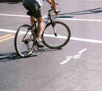
74 0

75 Technical Design Handbook, 2010 Bicycle Plan Section 6. Signalization As the needs and characteristics of bicycles and motor vehicles vary so greatly, adequately accommodating bicyclists at traffic signals can be challenging for traffic engineers. This chapter contains guidance on the detection of bicycles at signals, bicycle pavement markings at signals, and bicycle signals. Bicycle Considerations at Traffic Signals: Bicycles typically travel at speeds much slower than motor vehicles and can find themselves without an adequate time to clear an intersection. The duration of the amber phase of signals is typically sufficient to allow motor vehicles to clear an intersection at the prevailing speed; however, bicyclists typically average only mph through intersections. Methods for accommodating bicyclists include: Lengthening the amber phase of the intersection slightly to allow for the slower speed of bicyclists: This should only be part of the solution as longer amber phases can also encourage motor vehicles to enter intersections under this phase. Lengthening the all red phase of the intersection: This allows any vehicles or bicycles still in the intersection to clear before a green phase is given to opposing traffic. The maximum length of the all red phase should not generally be greater than 3 seconds. Under no circumstances should this time be extended beyond 6 seconds as this may also encourage motor vehicles to illegally enter the intersection. Coordinating signals to allow for the mph propagation speed of bicyclists: Sometimes it is possible to alter signal timing to provide green waves for bicyclists without significantly impeding motor vehicle flow or in specific circumstances, such as business districts with pedestrian volumes to discourage motor vehicle speeds. Increasing the minimum green phase: Bicyclists have slower speeds and accelerations than motor vehicles and even if they are at the stop line when a green light is given, the bicyclist may still lack sufficient time to clear the intersection before a conflicting green phase. 6 75
76 Using signal detection to detect moving bicyclists: Video detection technology may be programmed to detect the presence of bicyclists and alter the minimum green phase, or the clearance interval based on their presence Loop Detectors Design Summary In order to minimize delay to bicyclists, it is recommended to install one loop about 100 ft from the stop bar within the bicycle lane, with a second loop located at the stop bar. Details of saw cuts and winding patterns for inductive detector loop types appear on Caltrans Standard Detail ES-5B. Discussion The Type E loop is standard for use in the City of Los Angeles. Guidance California MUTCD Caltrans Highway Design Manual Caltrans Standard Plans (1999) ES-5B AASHTO Guide for the Development of Bicycle Facilities Design Example Diagonal Quadracircle Type E Detects at Edges Weakest in the middle Easy installation and maintenance 76 6
77 Technical Design Handbook, 2010 Bicycle Plan Additional Discussion Loop Detectors A Caltrans Traffic Operations Policy Directive effective September 10, 2009 incorporates new language in the California MUTCD regarding the detection of bicyclists at intersections. From Traffic Operations Policy Directive number 09-06: Section 4A.02 Definitions Relating to Highway Traffic Signals 15. Detector a device used for determining the presence or passage of vehicles (including motorcycles), bicycles or pedestrians. 29A. Limit Line Detection Zone a Referenced Bicycle Rider must be detected in a 6ft x 6 ft area immediately behind the limit line, centered either in a normal width lane or if the lane is more than 12 ft wide, centered 6 ft from the left lane line. For a lane of 20 ft or greater, two minimum 6 ft x 6 ft areas shall constitute the Limit Line Detection Zone. 50A. Reference Bicycle Rider a minimum 4 ft tall person, weighing minimum 90 lb, riding on an unmodified minimum 16-inch wheel bicycle with non-ferromagnetic frame, nonferromagnetic fork and cranks, aluminum rims, stainless steel spokes, and headlight. Section 4D.105(CA) Bicycle/Motorcycle Detection: Standard: All new limit line detector installations and modifications to the existing limit line detection on a public or private road or driveway intersecting a public road (see Section 1A.13 for definitions) shall either provide a Limit Line Detection Zone in which the Reference Bicycle-Rider is detected or be placed on permanent recall or fixed time operation. Refer to CVC All new and modified bike path approaches to a signalized intersection shall be equipped with either a Limit Line Detection Zone or a bicyclist pushbutton, or else the phase serving the bike path shall be placed on permanent recall or fixed time operation. A bicyclist pushbutton, if used shall be located on the right side of the bike path and where it can be reached form the bike path. See Section 9B.10 for bicycle regulatory signs. At new signalized intersections or when the advance detection is being replaced at existing signalized intersections, phases with advance detection only shall be placed on permanent recall. Support: The requirement to detect the Reference Bicycle-Rider in the limit line detection Zone is technology-neutral. 6 77
78 Option: The detection zone in a bike lane may be narrower than 6 ft. See Figure 4D-111(CA). A Bicycle Detector Symbol may be used. See Sections (B.12 and 9C.05). A bicyclist pushbutton may be used to supplement the required limit line detection. Support: See Section 9B.10 for bicycle regulatory signs. Guidance: If more than 50% of the limit line detectors need to be replaced at a signalized intersection, then the entire intersection should be upgraded so that every lane has a Limit Line Detection Zone. The Reference Bicycle-Rider or the equivalent should be used to confirm bicycle detection under the following situations: A. A new detection system has been installed; or B. The detection configuration has been modified. Support: CVC Section 21202(a) requires bicyclists traveling at a speed less than the normal speed of traffic to ride as close as practicable to the right-hand curb or edge of roadway with exceptions, including when the bicyclist is approaching a place where a right turn is authorized. This exception was intended to provide the bicyclist the flexibility to avoid having to ride against the right hand curb or edge of road where a potential conflict would be created with a right-turning motorist. A Limit Line Detection Zone provides for the detection of both bicycles and vehicles, including motorcycles. Guidance: Where a Limit Line Detection Zone that detects the Reference Bicycle-Rider has been provided, minimum bicycle timing should be provided as follows: For all phases, the sum of the minimum green, plus the yellow change interval, plus any red clearance interval should be sufficient to allow a bicyclist riding a bicycle 6 ft long to clear the last conflicting lane at a speed of 14.7ft/sec, where additional effective start-up time of 6 seconds, according to the formula Gmin + Y + Rclear 6 sec + (W+6 ft)/14.7 ft/sec, where Gmin = Length of minimum green interval (sec) Y = Length of yellow interval (sec) Rclear = Length of red clearance interval (sec) W = Distance from limit line to far side of last conflicting lane (ft) 78 6
79 Technical Design Handbook, 2010 Bicycle Plan Support: Bicyclist crossing times are shown in Table 4D-109(CA). The speed of 14.7ft/sec represents the final crossing speed and the effective start up time of 6 seconds represents the time lost in reacting to the green light and then accelerating to full speed. Option: A limit line detection system that can discriminate between bicyclists and vehicles may be used to extend the length of the minimum green. 6 79

80 6.2. Loop Detector Pavement Markings Design Summary Locate Bicycle Detector Pavement Marking where bicycle can be detected in a shared tunnel lane by loop detector or other detection technology. Discussion Bicycle Detector Pavement Markings guide bicyclists to position themselves at an intersection to trigger signal actuation. Efforts need to be made to ensure that signal detection devices are capable of detecting a bicycle. Detectors for traffic-actuated signals need to be located in the bicyclist s expected path, including left-turn lanes and shoulders. Marking the road surface to indicate the optimum location for bicycle detection is helpful to the bicyclist. Design Example Guidance California MUTCD AASHTO Guide for the Development of Bicycle Facilities Accompanying Signage (R10-22) Figure 9C-7 CA MUTCD 80 6


81 Technical Design Handbook, 2010 Bicycle Plan 6.3. Bicycle Signals Design Summary Part 4 of the California MUTCD covers bicycle signals. Support: Design Example Instruction Sign Signal Detection with Pavement Marking A bicycle signal is an electrically powered traffic control device that may only be used in combination with an existing traffic signal. Bicycle signals shall direct bicyclists to take specific actions and may be used to improve an identified safety or operational problem involving bicycles. Standard: Only green, yellow and red lighted bicycle symbols shall be used to implement bicycle movement at a signalized intersection. A separate signal phase for bicycle movement shall be used. Guidance: Alternative means of handling conflicts between bicycles and motor vehicles should be considered first. The application of bicycle signals shall be implemented only at locations that meet Department of Transportation Bicycle Signal Warrants. Two alternatives that should be considered are: 1. Striping to direct a bicyclist to a lane adjacent to a traffic lane such as a bicycle lane to left of a right-turn-only lane. 2. Redesigning the intersection to direct a bicyclist from an off-street path to a bicycle lane at a point removed from the signalized intersection. A bicycle signal phase should be considered only after these and other less restrictive remedies have had an adequate trial with enforcement and with the result that the collision frequency has not been reduced. Discussion Bicycle signals are an approved traffic control device in the State of California following an experiment in the City of Davis. Bicycle signals can be actuated with bicycle sensitive loop detectors, video detection, or push buttons. Instructional and regulatory signage should be considered with installation of new bicycle signals. This signage is not standard and will have to be created for the application. See images for examples and see the following page for additional discussion. Guidance Caltrans Highway Design Manual California MUTCD 6 81
82 Additional Discussion Bicycle Signals Use: Bicycle signals are typically considered in locations with heavy bicycle traffic combined with significant conflicts with motor vehicles, at intersections with unique geometry or at the interface between busy roads and off-street bicycle facilities. Specific situations where bicycle signals have had a demonstrated positive effect include: High volume of bicyclists at peak hours; High numbers of bicycle/motor vehicle crashes, especially those caused by crossing paths; At T-intersections with major bicycle movement along the top of the T; At the confluence of an off-street bicycle path and a roadway intersection; Where separated bicycle paths run parallel to arterial streets. Legal Clarification: While bicycle signals are approved for use in California, local municipal code should be checked or modified to clarify bicycles should only obey the bicycle signal heads at intersections with conflicting vehicular signalization. Advantages: Separates conflicting movements. Provides bicyclists priority movement at intersections. Protects bicyclist movements in an intersection, which may improve real and perceived safety at high conflict areas. Alternates right-of-way between different road users. Disadvantages: May result in additional delay for motorists and loss of vehicular capacity, particularly where a scramble phase is employed. May create a false sense of security for bicyclists because they believe the bicycle signal phase will protect them. Unfamiliar drivers may be confused or uncertain about intended purpose of signals. Design Exampl (Berkeley, CA) 82 6
83 e 0
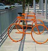
84 0
85 Technical Design Handbook, 2010 Bicycle Plan Section 7. Bicycle Parking Bicycle parking is a support facility that allows bicyclists to store their bicycles when they reach a destination. Bicycle parking can be separated into two categories: short term and long term. Short term bicycle parking is recommended when providing bicycle storage for short periods of time, errands or quick activities. Long term bicycle parking is recommended when providing bicycle storage for long periods of time, overnight, or possibly all day for commuters. General Design Guidance: Accessibility and Location: Bicycle parking should be placed as close as possible to the main entrance of a building/establishment. Racks should be placed no further than 50 feet away from the primary entrance of the establishment. This increases security and makes bicycling a visible travel option to bicyclists and non-bicyclists. Avoid placement around the corner or in an out-of-the-way place or put screening or landscaping around the parking. Hiding bicycle parking increases theft and vandalism. Make bicycle parking visible to bicyclists, building security, foot traffic, and anyone approaching the building. Making bicycle parking visible to foot traffic reduces the incidents of theft and vandalism. If possible, provide lighting for bicycle parking areas. Bicyclists, just like motorists, prefer to park in a well-lit place. If possible, provide a rack situated in an area that can cover the bicycle from the elements. Bicyclists don t want to sit on a wet seat or leave their bicycle out in the rain. Install parking devices, which support the frame of the bicycle at two points, not just the wheel. Poorly designed bicycle parking devices bend wheels and damage bicycles. In relation to the Public Right of Way: 7 85
86 Distance from a Curb: The bicycle rack should be situated 24 to 30 inches from the curb. The rack should align with existing street furniture. The rack should be placed parallel to the street. Distance from other Street Furniture: The rack should maintain 8 feet of clearance from other street furniture. Other street furniture includes but is not limited to: parking meters, trees, tree wells, newspaper racks, light poles, sign poles, telephone poles, utility meters, benches, mailboxes, fire hydrants, trash cans, other street furniture, and other sidewalk obstructions. Distance from other Bicycle Racks: The rack should allow a minimum of 4 feet of clearance when placed parallel to the roadway measured from center of base plate to center of base plate. The rack should allow sufficient space for any bicycle. A typical bicycle requires a clearance of 6 feet in length and at least two feet in width. Distance from Building: The rack should be a maximum of 50 feet from the front entrance of establishment. The rack should allow enough room between the rack and the entrance to the establishment. Bicycle racks should not impede access to a building. Bicycle racks should allow at least 5 feet of clearance on the sidewalk for pedestrian traffic. Other Distances: A bicycle rack shall not be installed in a bus stop zone. A bicycle rack should be placed at a minimum of 5 feet from a pedestrian crossing, driveways, alley entrances, and street corners/intersections. Bicycle racks should not be placed on top of gutters/storm drains or too close to signal boxes. 86 7
87 Technical Design Handbook, 2010 Bicycle Plan 7.1. Inverted U Bicycle Racks Design Summary Rack Dimensions: 43 high by 30 long. Construction: 2 3/8 x 2 x.188 wall single Schedule 40 ASTM A53 Steel pipe, constructed of a single 180 degree bend. Design Example Base Plate will be constructed of ASTM A36 with a thickness of 3/8 and will be welded onto the steel pipe. The base plate should be welded to the steel pipe and be constructed to receive mounting hardware with three 0.50 diameter holes at 120 degrees of each plate. Mounting Hardware: Mushroom Head, Stainless Steel Spike. 2 ¾ long by ½ diameter or equivalent vandal resistant hardware. Unacceptable fasteners include Threaded Spike or anything that contains sharp edges or can be vandalized. Coating Material Finish: Long wearing, mildew and ultraviolet ray resistant coating made of polyester, polyvinyl, thermoplastic or TGIC Powder Coating. Coated in the factory prior to delivery. Any damaged surface area resulted from the Contractor s operation shall be repaired with approved materials in accordance to the manufacturer s specifications. Discussion These racks are a common existing facility found in many areas in Los Angeles. Care should be taken to ensure that they are placed and installed correctly. Guidance APBP Bicycle Parking Guidelines Preferred Design 7 87
 Design Summary Alternate parking devices must meet the following criteria: Support the bicycle frame at two points not only by the wheel Must accept a")


88 7.2. Alternative Non-Standard Racks (Art Racks, etc.) Design Summary Alternate parking devices must meet the following criteria: Support the bicycle frame at two points not only by the wheel Must accept a variety of bicycle sizes and styles including various types and sizes of frames, wheel sizes, and tire widths. Must allow for the use of a cable as well as a U-shaped lock. Allow for the frame and at least one wheel of the bicycle to be locked to the rack. Must be tall enough to be seen by pedestrians and the visually impaired yet not be monumental in scale to the bicycles to be parked to the device. Must be maintenance free or fabricated from materials which wear in an aesthetically pleasing manner. Must have a simple, rather than complex, design which allows the user to easily figure out and utilize the rack. Moving parts are not acceptable or must be kept at a minimum. Must not require the user to lift the bicycle onto the parking device. Discussion While the Inverted-U design is the accepted standard for bicycle parking in the public right-of-way, other rack designs may be accepted for use at the discretion of LADOT and the department of Public Works. Guidance APBP Bicycle Parking Guidelines Design Example 88 7


89 Technical Design Handbook, 2010 Bicycle Plan Additional Discussion - Unacceptable Bicycle Racks Examples of inferior bicycle racks abound. The use of unacceptable bicycle parking facilities can discourage bicycling. Racks with the following characteristics should not be employed: Support bicycles at one point of contact; Support bicycles by one wheel; Allow bicycles to fall; bending the wheel and blocking the pedestrian right-of-way; Has sharp edges that can be hazardous to users and pedestrians; Requires the bicyclist to lift theire bicycle onto in. Examples of unacceptable bicycle racks. 7 89
90 Additional Discussion Rack Installation Racks will be affixed to City sidewalks or other concrete pad location by the utilization of vandal-resistant hardware provided by the installer and approved by LADOT. Racks will be installed in locations as designated by LADOT throughout the City of Los Angeles. In most cases racks will be sited for installation in clusters for a significant length of business districts in the city. Racks will be installed or removed in/from locations as designated by LADOT. All bicycle racks shall be installed at locations approved by City Engineer or LADOT staff. All installations shall conform to Americans with Disabilities Act (ADA) requirements. All bolt holes shall be clean of dust or any debris. The anchoring bolts should be driven vertically through the support plate into the bolt holes until the bolt head is firmly seated against the support plate. For pavement surfaces that are not level, use washers to level the rack and support plate. Fill with non-shrinking grout after the bicycle rack is mounted to the concrete. Do not place bicycle rack over any pavement expansion or control joint. Bicycle rack shall be placed at least 3 inches away from any expansion and or control joints in the cement. Requirements for Multiple Bicycle Parking Installation: Bicycle racks can be placed perpendicular, parallel or angled to a building. Allow ample room between bicycle rack and structure. Bicycle racks should be placed at least 30 inches from the structure When racks are placed side by side each rack should be spaced at least 48 inches from one another. Measured from the center of the rack. There should be sufficient room for a rider and a bicycle to fit in the aisle, the total width between bicycle racks should be at least 5 feet wide. 90 7
91 Technical Design Handbook, 2010 Bicycle Plan 7 91

92 0

93 Technical Design Handbook, 2010 Bicycle Plan Section 8. Bikeway Signage Bikeways have unique signage requirements and are included in chapter 9 of the Manual of Uniform Traffic Control Devices. This chapter summarizes the signs approved for use on all types of bikeway facilities in Los Angeles. It is recommended that the California Manual of Uniform Traffic Control Devices (CA MUTCD) be consulted during the design of any facility. The CA MUTCD provides the following standard and guidance for the application and placement of signs: Standard: Bicycle signs shall be standard in shape, legend, and color. All signs shall be retroreflectorized for use on bikeways, including shared-use paths and bicycle lane facilities. Where signs serve bicyclists as well as other road users, vertical mounting height and lateral placement shall be as specified in Part 2 (Signs). On shared-use paths, lateral sign clearance shall be a minimum of 3 ft and a maximum of 6 ft from the near edge of the sign to the near edge of the path. Mounting height for ground-mounted signs on shared-use paths shall be a minimum of 4 ft and a maximum of 5 ft, measured from the bottom edge of the sign to the near edge of the path surface (see Figure 9B-1). When overhead signs are used on shared-use paths, the clearance from the bottom edge of the sign to the path surface directly under the sign shall be a minimum of 8 ft. 8 93
94 Guidance: Signs for the exclusive use of bicyclists should be located so that other road users are not confused by them. The clearance for overhead signs on shared-use paths should be adjusted when appropriate to accommodate typical maintenance vehicles. Figure 5 12 Signage Placement 94 8
95 Technical Design Handbook, 2010 Bicycle Plan 8.1. Regulatory Signage (CA MUTCD) Description Facility Type CA MUTCD CODE Graphic STOP signs shall be installed on shared-use paths at points where bicyclists are required to stop. Bicycle Path Class I R1-1 YIELD signs shall be installed on shared-use paths at points where bicyclists have an adequate view of conflicting traffic as they approach the sign, and where bicyclists are required to yield the right-of-way to that conflicting traffic. Bicycle Path Class I R1-2 Where motor vehicles entering an exclusive right-turn lane must weave across bicycle traffic in bicycle lanes, the BEGIN RIGHT TURN LANE YIELD TO BIKES sign may be used to inform both the motorist and the bicyclist of this weaving maneuver. Bicycle Lane Class II R4-4 The NO MOTOR VEHICLES sign may be installed at the entrance to a shared-use path. Bicycle Path Class I R5-3 The Bicycle WRONG WAY sign and RIDE WITH TRAFFIC plaque may be placed facing wrong-way bicycle traffic, such as on the left side of a roadway. This sign and plaque may be mounted back-to-back with other signs to minimize visibility to other traffic. Bicycle Lane Class II R5-1b R9-3c If the installation of signs is necessary to restrict parking, standing, or stopping in a bicycle lane. Bicycle Lane Class II R26 Where pedestrians are prohibited, the No Pedestrians sign may be installed at the entrance to the facility. Bicycle Path Class I R9-3a 8 95

96 Description Facility Type CA MUTCD CODE Graphic The R9-5 sign may be used where the crossing of a street by bicyclists is controlled by pedestrian signal indications. Signal R9-5 The R9-6 sign may be used where a bicyclist is required to cross or share a facility used by pedestrians and is required to yield to the pedestrians. Signal R9-6 The Shared-Use Path Restriction (R9-7) sign may be installed on facilities that are to be shared by pedestrians and bicyclists. The symbols may be switched as appropriate. Bicycle Path Class I R9-7 Where it is not intended for bicyclists to be controlled by pedestrian signal indications, the R10-3 sign may be used. Signal R10-3 The Bicycle Signal Actuation sign may be installed at signalized intersections where markings are used to indicate the location where a bicyclist is to be positioned to actuate the signal Signal R10-22 The Bicycle Path Exclusion sign may be used to identify a bicycle path and prohibit motor vehicles and motorized bicycles from entering the bicycle path. If motorized bicycles are permitted, the Motorized Bicycles portion may be replaced with Motorized Bicycles Permitted. Bicycle Path Class I R44A Where it is not intended for bicyclists to be controlled by pedestrian signal indications, the BICYCLE PUSH BUTTON FOR GREEN LIGHT sign may be used. Signal R62C The BICYCLE LANE sign shall be placed at the beginning of each designated Bicycle Lane and along each bicycle lane at all major changes in direction. Bicycle Lane Class II R81 R81A R81C 96 8
97 Technical Design Handbook, 2010 Bicycle Plan 8.2. Guide Signage Description Facility Type CA MUTCD CODE Graphic If used, Bicycle Route Guide signs should be placed at the beginning and end of bicycle routes and repeated at regular intervals so that bicyclists entering from side streets will have an opportunity to know that they are on a bicycle route. Similar guide signing should be used for shared roadways with intermediate signs placed for bicyclist guidance. The M1-8 sign may be used on numbered routes. Bicycle Route Class III D11-1 M4-11 M4-12 M4-13 M1-8 If used, Bicycle Route Guide (D11-1) signs should be provided at decision points along designated bicycle routes, including supplemental signs to inform bicyclists of bicycle route direction changes and confirmation signs for route direction, distance, and destination. Option: The M4-11 through M4-13 supplemental plaques may be mounted above the appropriate Bicycle Route Guide signs, Bicycle Route signs, or Interstate Bicycle Route signs. Destination (D1-1b and D1-1c) signs may be mounted below Bicycle Route Guide signs, Bicycle Route signs, or Interstate Bicycle Route signs to furnish additional information, such as directional changes in the route, or intermittent distance and destination information. Guidance: M7-1 / M7-2 M7-3 / M7-4 M7-5 / M7-6 M7-7 D1-1b (R) D1-1b (L) D1-1 (c) If used, the appropriate arrow (M7-1 through M7-7) sign (see Figure 9B-4) should be placed below the Bicycle Route Guide sign. The BICYCLE PARKING AREA (D4-3) sign or BICYCLE PARKING (G93C(CA)) sign may be installed where it is desirable to show the direction to a designated bicycle parking area. The arrow may be reversed as appropriate. Bicycle Parking D4-3 G93C (CA) Directional sign for Los Angeles River bikeway access. This sign may be used on all City of Los Angeles Streets that permit bicycle access to the Los Angeles River Bicycle Path. Bicycle Path Class I S17 (CA) D11-1 M
98 8.3. Warning Signage Description Facility Type CA MUTCD CODE Graphic The Bicycle Warning sign alerts the road user to unexpected entries into the roadway by bicyclists, and other crossing activities that might cause conflicts. These conflicts might be relatively confined, or might occur randomly over a segment of roadway. This sign may use supplemental signs below the sign. Non Bikeway Facilities W11-1 Other bicycle warning signs such as SLIPPERY WHEN WET may be installed on bicycle facilities to warn bicyclists of conditions not readily apparent. All Bikeways W8-10 W8-10p Other bicycle warning signs such as Hill may be installed on bicycle facilities to warn bicyclists of conditions not readily apparent. All Bikeways W7-5 Other bicycle warning signs such as BIKEWAY NARROWS may be installed on bicycle facilities to warn bicyclists of conditions not readily apparent. Bicycle Path Class I W5-4a Other bicycle warning signs such as NARROW BRIDGE may be installed on bicycle facilities to warn bicyclists of conditions not readily apparent. All Bikeways W5-2 May be used to warn bicycle path users of pedestrian activity. Bicycle Path Class I W11-2 May be used to warn bikeway users of a traffic signal ahead. All Bikeways W3-3 Other bicycle warning signs such as BUMP may be installed on bicycle facilities to warn bicyclists of conditions not readily apparent. All Bikeways W8-1 Other bicycle warning signs such as DIP may be installed on bicycle facilities to warn bicyclists of conditions not readily apparent. All Bikeways W8-2 May warn bicycle path users of a playground ahead that may be adjacent to the path. Bicycle Path Class I W15-1 In situations where there is a need to warn motorists to watch for bicyclists traveling along the highway, the SHARE THE ROAD plaque may be used in conjunction with the W11-1 sign. Bicycle Route Class III W
99 Technical Design Handbook, 2010 Bicycle Plan 8.4. Temporary Traffic Control (TTC) Description Facility Type CA MUTCD CODE Graphic The PEDESTRIAN / BICYCLE DETOUR (M4-9a) should be used where a pedestrian/bicycle detour route has been established because of the closing of a pedestrian/ bicycle facility to through traffic. Standard: If used, the Pedestrian/Bicycle Detour sign shall have an arrow pointing in the appropriate direction. Bicycle Path Class I M4-9a The BICYCLE DETOUR (M4-9c) may be used where a pedestrian or bicycle detour route (not both) has been established because of the closing of a bicycle facility to through traffic. Bicycle Lane Class II; or Bicycle Route Class III M4-9c Several standard signs [W21-5, W21-5a, W21-5b, C24 (CA), C30A (CA), C31A (CA)] may be used to warn bicyclists of changes in conditions regarding the roadway shoulder. Bicycle Route Class III or other Shared Roadway W21-5a C24 (CA) 8 99
100 General Bicycle Considerations in Temporary Traffic Control Zones (from CA MUTCD Section 6D.101) Support: There are several considerations in planning for bicyclists in Temporary Traffic Control zones on highways and streets: A travel route that replicates the most desirable characteristics of a wide paved shoulder or bikeway through or around the traffic control zone is desirable for bicyclists. If the traffic control zone interrupts the continuity of an existing bikeway system, signs directing bicyclists through or around the zone and back to the bikeway is desirable. Unless a separate bicycle path through or around the traffic control zone is provided, adequate roadway lane width to allow bicyclists and motor vehicles to travel side by side through or around the zone is desirable. Bicyclists should not be led into direct conflicts with mainline traffic, work site vehicles, or equipment moving through or around the traffic control zone. Work Affecting Bicycle Facilities (from CA MUTCD Section 6G.05) Support: It is not uncommon, particularly in urban areas, that road work and the associated TTC will affect existing pedestrian or bicycle facilities. It is essential that the needs of all road users, including pedestrians with disabilities, are considered in TTC zones. In addition to specific provisions identified in Sections 6G.06, 6G.07, 6G.08, 6G.10, 6G.11, 6G.12, and 6G.13, there are a number of provisions that might be applicable for all of the types of activities identified in this Chapter. Guidance: Where pedestrian or bicycle usage is high, the typical applications should be modified by giving particular attention to the provisions set forth in Chapters 6D and 6G, Section 6F.68, and in other Sections of Part 6 related to accessibility and detectability provisions in TTC zones. Bicyclists and pedestrians should not be exposed to unprotected excavations, open utility access, overhanging equipment, or other such conditions. Except for short duration and mobile operations, when a highway shoulder is occupied, a SHOULDER WORK sign should be placed in advance of the activity area. When work is performed on 100 8
101 Technical Design Handbook, 2010 Bicycle Plan a paved shoulder 8 ft or more in width, channelizing devices should be placed on a taper having a length that conforms to the requirements of a shoulder taper. Work Within the Traveled Way of Urban Streets (from CA MUTCD Section 6G.11) Support: In urban TTC zones, decisions are needed on how to control vehicular traffic, such as how many lanes are required, whether any turns need to be prohibited at intersections, and how to maintain access to business, industrial, and residential areas. Standard: If the TTC zone affects the movement of bicyclists, adequate access to the roadway or shared-use paths shall be provided. Guidance: If a designated bicycle route is closed because of the work being done, a signed alternate route should be provided. Bicyclists should not be directed onto the path used by pedestrians
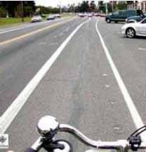
102 0
103 Technical Design Handbook, 2010 Bicycle Plan Section 9. Non-Standard Treatments Standard bicycle facility treatments do not always provide enough options when developing bikeways to retrofit the existing built environment. Narrow rights-of-way, off angled intersections, limited opportunities, and unique roadway geometry may warrant the use of context sensitive, non-standard treatments. This chapter discusses unique treatments and signage that are gaining acceptance across the nation. None of the treatments discussed in this chapter are contained within the standards set forth by the California MUTCD or Caltrans HDM. Any application of these treatments should follow the processes outlined on the following pages through the California Traffic Control Devices Committee (CTCDC) and the Federal Highway Administration (FHWA) for pilot project experimentation. Installations of non-standard treatments without going through CTCDC or FHWA process could result in additional liability for the City of Los Angeles. It is not recommended to proceed on a non-standard project without conducting an official experiment through the CTCDC and FHWA. The following is a summary of the FHWA experimentation procedure: All requests for experimentation should originate with the State/ local highway agency or toll operator responsible for managing the roadway or controlled setting where experiment will take place. That organization forwards the request to the FHWA - with a courtesy copy to the FHWA Division Office. The FHWA must approve the experiment before it begins. Requests may also be forwarded directly to the FHWA Division Office, and the Division Office can submit the request to the FHWA Headquarters Office. All requests must include: 1. A statement of the nature of the problem, including data that justifies the need for a new device or application. 2. Describe the proposed change, how it was developed, how it deviates from the current MUTCD. 3. Any illustration(s) that enhance understanding of the device or its use. 4. Supporting data that explains how the experimental device was developed, if it has been tried, the adequacy of its performance, and the process by which the device was chosen 9 103
104 or applied. 5. A legally binding statement certifying that the concept of the traffic control device is not protected by a patent or copyright (see MUTCD Section IA.10 for additional details.) 6. The proposed time period and location(s) of the experiment. 7. A detailed research or evaluation plan providing for close monitoring of the experimentation, especially in the early stages of field implementation. The evaluation plan should include before and after studies as well as quantitative date enabling a scientifically-sound evaluation of the performance of the device. 8. An agreement to restore the experimental site to a condition that complies with the provisions of the MUTCD within 3 months following completion of the experiment. The agreement must also provide that the sponsoring agency will terminate the experiment at any time if it determines that the experiment directly or indirectly causes significant safety hazards. If the experiment demonstrates an improvement, the device or application may remain in place as a request is made to update the MUTCD and an official rulemaking action occurs. 9. An agreement to provide semiannual progress reports for the duration of the experimentation and to provide a copy of the final results to the Office of Transportation Operations (HOTO) within three months of the conclusion of the experiment. HOTO may terminate approval of the experimentation if these reports are not provided on schedule

105 Technical Design Handbook, 2010 Bicycle Plan Obtaining FHWA Experimentation Approval for New Traffic Control Devices 9 105
106 Example of Process for Requesting and Conducting Caltrans Experimentations for New Traffic Control Devices in California 106 9

107 Technical Design Handbook, 2010 Bicycle Plan 9.1. Wide Bicycle Lane with Additional Pavement Markings Next to On-Street Parallel Parking Design Summary Bicycle Lane Width: 7 maximum (may encourage vehicle loading in bicycle lane) Discussion Bicycle lanes adjacent to on-street parallel parking are common in the United States. Crashes caused by a suddenly opened vehicle door are a common hazard for bicyclists using this type of facility. Wide bicycle lanes may encourage un-experienced bicyclist to ride farther to the right (door zone) to maximize distance from passing traffic. Wide bicycle lanes may also encourage vehicles to use the bicycle lane as a loading zone in busy areas where on-street parking is typically full. Encouraging bicyclists to ride farther away from parked vehicles will increase the safety of the facility. Installing smaller bicycle lane stencils placed to the left of are a method to increase separation. Minimum Design Diagonal stripes may be added to encourage bicyclists to ride to the left of the bicycle lane. This treatment is not standard and should be studied before use. Providing a buffer between parking stalls and the outside bicycle lane stripe are preferred (see Preferred Design for Bicycle Lane Next to On-Street Parallel Parking). However, the treatment at right may in used in areas where parking stalls are undesirable or otherwise cannot be used. Guidance This treatment is not currently present in any State or Federal design standards This treatment is currently included in the San Francisco Bicycle Design Guidelines
 Discussion Design Example In certain areas with high parking demand such as urban commercial")
108 9.2. Bicycle Lane Next to Back-in On-Street Diagonal Parking Design Summary Bicycle Lane Width: 5 minimum White 4-inch stripe separates bicycle lane from parking bays. Parking bays are sufficiently long to accommodate most vehicles (vehicles do not block bicycle lane) Discussion Design Example In certain areas with high parking demand such as urban commercial areas, diagonal parking can be used to increase parking supply. Conventional diagonal parking is not compatible or recommended in conjunction with high levels of bicycle traffic. Drivers backing out of conventional diagonal parking have poor visibility of approaching bicyclists. The use of back-in diagonal parking or reverse angled parking is recommended over head-in diagonal parking. This design addresses issues with diagonal parking and bicycle travel by improving sight distance between drivers and bicyclists and has other benefits to vehicles including: loading and unloading of the trunk occurs at the curb rather than in the street, passengers (including children) are directed by open doors towards the curb, vehicle headlights are not directed into homes and businesses, and there is no door conflict with bicyclists. While there may be a learning curve for some drivers, using back-in diagonal parking is typically an easier maneuver than conventional parallel parking. Guidance This treatment is not currently present in any State or Federal design standards but is now a standard configuration for angled parking in Seattle, WA

109 Technical Design Handbook, 2010 Bicycle Plan Recommended Design 9 109
 Discussion Contra-flow bicycle lanes enable bicyclists to ride in the opposite direction of vehicle traffic on one-way streets for local access.")

.")
110 9.3. Contra-Flow Bicycle Lane on One-Way Street Design Summary Bicycle Lane Width: 5 minimum when adjacent to curb and gutter 5 recommended if next to on-street parallel parking (if applicable non-contra-flow direction only) Discussion Contra-flow bicycle lanes enable bicyclists to ride in the opposite direction of vehicle traffic on one-way streets for local access. The facility is placed on the opposite side of vehicle travel lanes (to the motorists left), and separated from traffic with a double yellow line or extruded curb. This informs motorists that bicyclists are riding legally in a dedicated lane. Design Example Measures should be taken to signalize all stop-controlled intersections on streets with contra flow bicycle lanes. All leftturn-on-red movements from intersecting one-way streets onto the street with the contra-flow bicycle lane should be prohibited (R-13B). If driveways exist, exiting left turns should be prohibited if possible by relocating exit movements to other streets. If left turn out of driveways onto the street with the contra-flow bicycle lane must be permitted, special signage should be developed warning motorists to look left for approaching bicyclists before turning left. R-13B (CA) See following page for additional discussion. Guidance There is no currently adopted Federal or State guidance for this treatment. Contra-flow bicycle lanes exist in several U.S. cities, including Boise, Idaho; Boulder, Colorado; Minneapolis, Minnesota; Cambridge, Massachusetts; and Eugene and Portland, Oregon. Recommended Design 110 9
111 Technical Design Handbook, 2010 Bicycle Plan Additional Discussion - Contra-Flow Bicycle Lane on One-Way Street Contra-flow lanes may be considered where the following conditions exist: When alternate routes require excessive out-of-direction travel. When alternate routes include unsafe or uncomfortable streets with high traffic volumes and/or no bicycle facilities. When the contra-flow lane provides direct access to bicyclist destinations on the street under consideration. When few intersecting streets, alleys or driveways exist on the side of the contra-flow lane. When bicyclists can safely and conveniently re-enter the traffic stream where the contra-flow lane ends. To ensure bicyclist safety on streets with contra-flow lanes: Signs should be posted at intersecting streets, alleys and driveways informing motorists to expect two-way traffic. Example signs include a Do Not Enter or One-Way sign with an Except Bicycles sign below. Intersection traffic controls along the street (e.g., stop signs and traffic signals) should also be installed and oriented toward bicyclists in the contra-flow lane. On-street parking should be prohibited between the contraflow lane and the curb to prevent motorists from crossing the bicycle lane in the wrong direction. Advantages of a left handed bicycle lane on a one-way street: Decreases trip distance, the number of intersections encountered, and travel times for bicyclists by eliminating out-of-direction travel. Provides separate facility for bicycles traveling against motor vehicle traffic. Disadvantages / potential hazards: Motorists turning left onto one way street may not expect contra-flow bicyclists (may require prohibition of left turns on red from intersecting streets onto one-way street). Some motorists may use the bicycle lane for left-turn movements. Contra-flow bicycle lane may require the reduction in parking or vehicle through lane capacity. Conflicts of vehicles at driveways Conflicts at crossings 9 111

112 9.4. Bicycle Only Left Turn Pocket Design Summary Bicycle Lane Width: Bicycle Lane pocket should be 4 minimum in width, with 5 preferred. Discussion A left-turn pocket allows only bicycles left turn access to a Bicycle Friendly Street or designated bikeway. If the intersection is controlled the left-turn pocket may have a left arrow signal, depending on bicycle and vehicle volumes. Signs and raised median design restrictions should be provided that prohibit motorists from turning, while allowing access to bicyclists. Bicycle signal heads may also be used at busy or complex intersections. Ideally, the left turn pocket should be protected by a raised curb, but the pocket may also be defined by striping only if necessary. This treatment typically should be applied on lower volume arterials and collectors. Portland, Oregon Design Example Guidance There is no currently adopted Federal or State guidance for this treatment. This treatment is currently used in Portland, Oregon. Recommended Design 112 9
 Discussion Design Example A contrasting color for the paving of bicycle lanes can also be applied to continuous sections of roadways.")

113 Technical Design Handbook, 2010 Bicycle Plan 9.5. Colored Bicycle Lanes Design Summary Bicycle Lane Width: 5 minimum and 7 maximum. (See sections Chapter 1 and for more detailed discussion of bicycle lane widths.) Discussion Design Example A contrasting color for the paving of bicycle lanes can also be applied to continuous sections of roadways. These situations help to better define road space dedicated to bicyclists and make the roadway appear narrower to drivers resulting in beneficial speed reductions. Colored bicycle lanes require additional cost to install and maintain. Techniques include: Paint which is less durable and can be slippery when wet. Thermoplastic which is expensive, durable but slippery when worn. Colored asphalt colored medium applied to asphalt during construction is the most durable. Colored and textured sheets of acrylic epoxy coating. Guidance This treatment is not currently present in any State or Federal design standards Recommended Design Before After 9 113
114 9.6. Colored Bicycle Lanes in Conflict Areas Design Summary Bicycle Lane Width: See section 5.4. Discussion Some cities in the United States are using colored bicycle lanes to guide bicyclists through major vehicle/bicycle conflict points. Color Considerations: There are three colors being used in bicycle lanes: blue, green, and red. All help the bicycle lane stand out in merging areas. The City of Portland began using blue lanes and changed to green in April Green is the color being recommended for use at the Federal level for inclusioning the MUTLD. See following page for additional discussion: Guidance This treatment is not currently present in any State or Federal design standards Portland s Blue Bicycle Lanes shared/cfm/image.cfm?id=58842 City of Chicago - Green Pavement Markings for Bicycle Lanes (Ongoing) - FHWA Experiment No. 9-77(E) Design Example Recommended Design 114 9
115 Technical Design Handbook, 2010 Bicycle Plan Additional Discussion - Colored Bicycle Lanes in Conflict Areas Guidance: Colored bicycle lanes can be used in conflict areas or locations where motorists and bicyclists must cross each other s path (e.g., at intersections freeway ramps or merge areas). Bicyclists are especially vulnerable at locations where the volume of conflicting vehicle traffic is high, and where the vehicle/bicycle conflict area is long. Colored bicycle lanes typically extend through the entire bicycle/vehicle conflict zone (e.g., through the entire intersection, or through the transition zone where motorists cross a bicycle lane to enter a dedicated right-turn lane. Although colored bicycle lanes are not an official standard in California at this time, they continue to be successfully used around the country. Portland, Oregon, Chicago, Illinois, Philadelphia, Pennsylvania, Cambridge, Massachustts, Mammoth Lakes, California and Tempe, Arizona, have used colored bicycle lanes in select locations. This treatment typically includes accompanying signage alerting motorists of vehicle/bicycle conflict points. Portland s Blue Bicycle Lane report found that significantly more motorists yielded to bicyclists and slowed or stopped before entering the conflict area after the application of the colored pavement. In areas of high vehicle traffic, thermoplastic application with proper friction coefficient for ongoing bicycle use (as opposed to paint) is recommended. At high volume intersections, the thermoplastic treatment has shown to significantly prolong the life of the marking, thus off-setting the additional cost for the treatment by lowering the frequency of required maintenance. Advantages of colored bicycle lanes at conflict points: Draws attention to conflict areas. Results in more consistent yielding behavior by motorists. Emphasizes expectation of bicycles in the road way. Disadvantages / potential hazards: Currently non-standard treatment with increased agency liability. Maintenance to repain or replace treatment. Potential slipping hazard in wet conditions
116 9.7. Colored Bicycle Lanes at Interchanges Design Summary Bicycle Lane Width: The bicycle lane width through the interchange should be the same width as the approaching bicycle lane (minimum five feet). Additionally, bicycle lane should follow guidance in sections through Discussion On high traffic bicycle corridors non-standard treatments may be desirable over current practices outlined in Figure 9C-104 in the CA MUTCD. Dashed bicycle lane lines with or without colored bicycle lanes may be applied to provide increased visibility for bicycles in the merging area. See 9.6 Colored bicycle lanes in conflict areas. Guidance This treatment is not currently present in any State or Federal design standards City of Chicago - Green Pavement Markings for Bicycle Lanes (Ongoing) - FHWA Experiment No. 9-77(E) Portland s Blue Bicycle Lanes shared/cfm/image.cfm?id=58842 Design Example Recommended Design 116 9


117 Technical Design Handbook, 2010 Bicycle Plan 9.8. Bicycle Box Single Lane - No Vehicle Right Turns Design Summary Bicycle Box Dimensions: The Bicycle Box should be 14 deep to allow for bicycle positioning. Signage: Appropriate signage as recommended by the CA MUTCD applies. Signage should be present to prevent right turn on red and to indicate where the motorist must stop. Design Example Discussion Bicycle boxes provide additional space for bicyclists to move to the front of the vehicular queue while waiting for a green light. On a two-lane roadway, the bicycle box can also facilitate left turning movements for bicyclists as well as through bicycle traffic. Motor vehicles must stop behind the white stop line at the rear of the bicycle box and may not turn right on red. Guidance This treatment is not currently present in any U.S. State or Federal design manuals. Examples of this treatment can be found in Cambridge, (Mass.) Portland, Oregon and Vancouver, Washington. Recommended Design Bike Box - Colored 9 117


118 9.9 Shared lane Marking with Colored Pavement Design Summary A standard Shared Roadway Bicycle Marking per CAMUTCD, is used in conjunction with colored pavement to indicate optimal lane position for bicyclists on an urban, multilane roadway with parallel on-street parking. Discussion Cities such as Salt Lake City, Utah and Long Beach, California have used colored pavement in conjunction with shared lane markings to further indicate the appropriate position for bicyclists using the roadway. Increasing the distance from the curb face to the center of the shared lane marking to 11 feet at center and adding a green stripe provides the following benefits: Reduces the probability that bicyclists riding over the marking could be impacted by opening car doors. Brings the marking more directly and continuously into the line of sight of drivers. Reduces wear on the markings by placing them in a location where they will typically track between car tires. Design Example Guidance For shared lane markings only, see CAMUTCD. The combination of shared lane markings with colored pavement is not currently present in any State or Federal design standards. See the CTCDC website for a Progress report for green and shared lane marking and bikes in lane symbol sign on 2nd street in Long Beach. Recommended Design 118 9

 on streets without parking where the outside travel lane is less than 14 wide on roadways where the pooled speed is less")
119 Technical Design Handbook, 2010 Bicycle Plan Shared Lane Markings (SLM) on Streets without Parking Design Summary Design Example (Berkeley, CA) Recommended SLM placement without parking: Center of the SLM should be placed a minimum of 4 from the face of the curb (or from the edge of the pavement where there is no curb) on streets without parking where the outside travel lane is less than 14 wide on roadways where the pooled speed is less than 40 miles per hour. Discussion Shared Lane Marking stencils (also called Sharrows ) were adopted for official use by Caltrans in the 2003 MUTCD but are only currently allowed in conjunction with on-street parking. The Federal 2009 MUTCD provides guidance for shared lane marking on streets without parking. The stencil can serve a number of purposes, such as making motorists aware of bicycles potentially in the lane, and showing bicyclists the correct direction of travel. Guidance MUTCD 2009 (Federal) Recommended Design 9 119


120 9.11. Bicycle Box Multi Lane - Right Turns Allowed Design Summary Bicycle Box Dimensions: The Bicycle Box should be 14 deep to allow for bicycle positioning. Signage: Appropriate signage as recommended by the CA MUTCD applies. Discussion In some areas there may be a situation where a freeway ramp exists where bicycles are prohibited or areas where bicycles may not need to access such as parking garages. In these limited cases a vehicle right turn only lane may be provided to the outside of the bicycle box. Right turns on red are permitted in these instances. Guidance This treatment is not currently present in any U.S. or Federal design manuals Recommended Design 120 9
121 Technical Design Handbook, 2010 Bicycle Plan Bicycle Box General Discussion Guidance: A bicycle box is generally a right angle extension to a bicycle lane at the head of a signalized intersection. Bicycle boxes should be used with a separate signal phase and at intersections where left-turning bicyclists face high volumes of traffic. Bicycle Boxes should be located at signalized intersections only, and right turns on red should be prohibited unless a separate right turn pocket is provided to the right of the bicycle box. Bicycle Boxes can exist in several configurations illustrated on the following pages. Design Summary: Bicycle Boxes typically include the following features: A striped bicycle lane: Allows bicyclists to safely maneuver to the head of the line of stopped vehicles. An advanced vehicle stop bar located several feet upstream from the intersection: Provides a space for bicyclists to move directly in front of the vehicle at the head of the line, increasing motorists visibility of bicyclists. Bicycle pavement markings in the bicycle box: Advises motorists to stay out of the bicycle box. Signage: Advising motorists to stop behind the Bicycle Box (R10-6a) and if applicable, that there are no right turns on red (R10-11). Bicycle boxes offer several advantages: Bicyclists making left turns can safely position themselves in the bicycle box in front of motor vehicle traffic, as opposed to merging with vehicle traffic as they approach the intersection. Enabling bicyclists to move to the head of the line, bicycle boxes reduce bicyclist waiting time and increase the likelihood that a bicyclist can clear an intersection during the signal phase. Bicyclists at the head of the line can avoid breathing exhaust fumes from vehicles idling at the intersection. Bicycle Boxes have been installed in the United States with striping only or with colored treatments to increase visibility. Bicycle boxes are a common treatment in European cities, though their use has increased throughout North American cities, including Cambridge, Massachusetts, Eugene and Portland, Oregon, and Vancouver, British Columbia

122 9.12. Raised Bicycle Lanes Design Summary Bicycle Lane Width: 5 feet minimum. Bicycle lane should drain to street. Drainage grates should be in travel lane. Mountable Curb Design: Mountable curb should have a 4:1 or flatter slope and have no lip that could catch bicycle tires. Signage & Striping: Same as traditional Class II bicycle lanes. See section 5.4. Discussion Raised bicycle lanes are bicycle lanes that have a mountable curb separating them from the adjacent travel lanes. Raised bicycle lanes provide an element of physical separation from faster moving vehicle traffic. For drivers, the mountable curb provides a visual and tactile reminder of where the bicycle lane is. For bicyclists the mountable curb makes it easy to leave the bicycle lane if necessary, such as when passing another bicyclist, or to merge to the left for turning movements. The raised bicycle lane should return to level grade at intersections. Raised bicycle lanes cost more than traditional bicycle lanes and typically require a separate paving operation. Maintenance costs are lower may be accessed by sweaper vehicles as the bicycle lane receives no vehicle wear and resists debris accumulation. Raised bicycle lanes work well adjacent to higher speed roadways with few driveways. Guidance This treatment is not currently present in any U.S State or Federal design manuals CROW Design Manual for Bicycle Traffic Design Example Recommended Design 122 9

123 Technical Design Handbook, 2010 Bicycle Plan Cycle Tracks - Protected Bicycle Lanes Design Summary Cycle Track Width: 7 feet minimum to allow passing and obstacle avoidance 12 feet minimum for two-way facility Discussion Design Example A cycle track is a hybrid type bicycle facility that combines the experience of a separated path with the on-street infrastructure of a conventional bicycle lane. Cycle tracks have different forms, but all share common elements. Cycle tracks provide space that is intended to be exclusively or primarily for bicycles, and is separated from vehicle travel lanes, parking lanes and sidewalks. Cycle tracks can be either one-way or two-way, on one or both sides of a street, and are separated from vehicles and pedestrians by pavement markings or coloring, bollards, curbs/medians and on-street parking or a combination of these elements. Guidance This treatment is not currently present in any U.S. State or Federal design manuals 9th Avenue New York City CROW Design Manual for Bicycle Traffic - Chapter 5 Recommended Design No Parking Recommended Design On-Street Parking 9 123
124 Additional Discussion - Cycle Tracks - Protected Bicycle Lanes Separation: Cycle tracks can be separated by a barrier or by on-street parking. Cycle tracks using barrier separation are typically at-grade. Openings in the barrier or curb are needed at driveways or other access points. The barrier should be dropped at intersections to allow vehicle crossing. When on-street parking is present, it should separate the cycle track from the roadway, the cycle track should be placed with a 2-foot (min.) buffer between parking and the cycle track to minimize the hazard of opening car doors into passing bicyclists. Placement: Cycle tracks should be placed along slower speed urban/suburban streets with long blocks and few no driveway or midblock access points for vehicles. Cycle tracks located on one-way streets will have fewer potential conflicts than those on two-way streets. A two-way cycle track is desirable when there are more destinations on one side of a street or if the cycle track will be connecting to a shared use path or other bicycle facility on one side of the street. Cycle tracks should only be constructed along corridors with adequate right-of-way. Sidewalks or other pedestrian facilities should not be narrowed to accommodate the cycle track, as pedestrians will likely walk on the cycle track if sidewalk capacity is reduced. Visual and physical cues should be present that make it easy to understand where bicyclists and pedestrians should be moving. Intersections: Cycle tracks separate bicyclists and motor vehicles to a greater degree than bicycle lanes. This produces added comfort for low speed for bicyclists on the cycle track, but it creates additional considerations at intersections that must be addressed. Right and left turning motorists conflicting with cycle track users is the most common conflict. Both roadway users have to expand their visual scanning to see potential conflicts. To mitigate for this issue, several treatments can be applied at intersections: Protected Phases at Signals. This treatment MUST have separate signal phases for bicyclists and will potentially increase delay. With this treatment, left and right turning movements are separated from conflicting through movements. The use of a bicycle signal head is required in this treatment to ensure all users know which signals to follow. Demand only bicycle signals can be implemented to reduce 124 9
125 Technical Design Handbook, 2010 Bicycle Plan vehicle delay to prevent an empty signal phase from regularly occurring. With this scenario, a push button or imbedded loop within the cycle track should be available to actuate the signal. If frequent bicyclist left turns are expected incorporate a bicycle box. Bicyclists movements should be given their own signal phase and signal activation. Advanced Signal Phases. Signalization utilizing a bicycle signal head can also be set to provide cycle track users a green phase in advance of vehicle phases. The amount of time will depend on the width of the intersection. Access Management. The reduction in the number of potential conflict points can also benefit a cycle track corridor. Medians, driveway consolidations, or restricted movements reduce the potential for conflict. Advantages: Well designed facilities have been proven to increase bicycle ridership where implemented (e.g. Portland, Oregon, Minneapolis, Minnesota). Cycle tracks provide increased comfort for bicyclists and greater clarity about expected behavior on the part of both bicyclists and motorists. Properly designed cycle tracks eliminate conflicts between bicyclists and parking motorists by placing the cycle track on the inside of the parking lane. Barriers used along cycle tracks to separate parking and travel lanes from bicyclists provide adequate space to mitigate or remove the danger of car dooring. Disadvantages: Can create unusual situations at intersections for vehicles. Can be expensive to correctly implement. Can require closures/restrict vehicle access from driveways, alleys, and parking lots through access management planning. Left turns can be complicated for bicyclists and may cause delay due to bicyclist only signal phasing. May be difficult for existing street maintenance equipment to maintain cycle track (sweepers etc.) 9 125

126 9.14. Bicycle Route/BFS at Local Misaligned Unsignalized Intersections Bicycle Pockets Design Summary Bicycle Turn Pocket Width: The bicycle turn pockets should be 5 feet wide, with a total of 11 feet required for both turn pockets and center striping. Treatments should also be made to prohibit motor vehicle left turn movements. Discussion Bicycle routes or Bicycle Friendly Streets crossing major streets at offset intersections can incorporate bicycle left-turn lanes to facilitate easier bicyclist crossings Similar to medians/refuge islands, bicycle left-turn lanes allow the crossing to be completed in two phases. A bicyclist on the Bicycle Friendly Street could execute a right-hand turn onto the cross-street, and then wait in a delineated left-turn lane (if necessary to wait for a gap in oncoming traffic). If traffic volumes are moderate the prohibition of vehicle left turns may reduce conflicts between bicyclists and vehicles. Guidance This treatment is not currently covered in any established standards Design Example Recommended Design 126 9

127 Technical Design Handbook, 2010 Bicycle Plan Bicycle Route/BFS at Local/Major Misaligned Unsignalized Intersections Bicycle Pockets Design Summary Design varies: Bicycle pockets should be 5 wide minimum. Openings in median/bicycle pocket should be wide enough to accommodate two bicyclists waiting for a traffic gap. Bicycle pockets should be only delineated with paint. Discussion Misaligned intersections of local and major streets can cause discontinuity in the bicycle network and make bicycle routes/ Bicycle Friendly Streets difficult to fully implement. The concepts below are suggestions for providing bicycle facilities to close similar gaps in Los Angeles. In examples A and B below, a longer offset is represented. Road space can be taken from a median, center turn lane, or on-street parking to create a twoway bicycle pocket to better facilitate a connection for bicyclists. In example C a shorter offset allows for a narrower facility consisting of two left turn pockets. Guidance This treatment is not currently covered in any established standards Recommended Design (not to scale) 9 127


128 9.16 Bicycle Rail for Paths at Roadway Intersections Design Summary Steel or stainless steel rail placed on urban bicycle paths where the paths intersect with roadways. Discussion Bicycle friendly nations with extensive off-street bikeway networks have added to the convenience of bicyclist by adding lean rails for bicyclists who wait for clearance at the intersection. Guidance Copenhagan Design Example Copenhagan 128 9

129 Technical Design Handbook, 2010 Bicycle Plan 9.17 Bicycle Track for Staircases Design Summary Design Example Retrofit stairwells for bicycles by adding channels or ramps to the stairs. A channel can be fabricated of stock steel and has one or two sides to guide the bike s wheels and keep them from straying. Some channels are made of U shaped stock or L shaped steel angles. The upright of the L goes next to the outside and the bike leans against the bicyclist for stability. Its always is best to provide a track for bicycles by integrating the concept into the design prior to construction of Bicycle tire width. Add grit or grip tape to the steel surface to provide ease of use with rubber bicycle tires. Discussion Include in the design of new stairways or retrofit existing structures where bicycles are expected such as transit stations, under and over passes, and bicycle accessible tunnels. Should include the provision of a wheel track in order to accommodate bicycle wheels to allow bicyclists to access the location Guidance U.S. examples can be found in Denver, Chicago, San Francisco, and Los Angeles. Recommended Design Cycling England s Design Portfolio, Wheeling Ramps
130 9.18. Non-Standard Bikeway Signage In addition to the standard bikeway signage described in the MUTCD and the CA MUTCD, nonstandard signs may be useful in some situations. The following table provides some examples. Description Facility Type MUTCD CODE Graphic An alternative to Share the Road, this regulatory sign instructs vehicles that bicyclists are permitted full use of the lane travel lane when necessary. Bicycle Route Class III or other Shared Roadway R4-11 (under consideration) Another alternative to Share the Road, this warning sign instructs vehicles that bicyclists are to be expected in the lane. Bicycle Route Class III or other Shared Roadway N/A This alternative warning sign has been used in Los Angeles. Bicycle Route Class III or other Shared Roadway N/A This sign may be used where bicycle lanes are interrupted by a double right turn lane, and is currently in use in the City of Los Angeles. Bicycle Lane Class II N/A This sign may be used with a Shared Bicycle / Right Turn Lane. Bicycle Lane Class II N/A 130 9
131 Technical Design Handbook, 2010 Bicycle Plan Description Facility Type MUTCD CODE Graphic This sign instructs motorists to yield to bicyclists in a bicycle lane. The colored lane alerts motorists to the potential conflict area where motorists may merge across a bicycle lane. Bicycle Lane Class II N/A Mileage wayfinding signage specifically targeting bicyclists can be extremely helpful, helping people anticipate both distance and direction to their next destination. Wayfinding Mileage Sign D1-3c Instructional signage similar to the image at right may be used in conjunction with Bicycle Signals where movements from a bicycle path onto a roadway intersection are made during an exclusive phase. Intersections Bicycle Path Class I N/A Directional Sign for River Access these signs are used where bikeway access is currently non-existent.* Bicycle Path Class I N/A Park Entry Signs These signs provide directional wayfinding to parks or other bikeway facilities connecting to the Los Angeles River bikeway.* Bicycle Path Class I N/A Los Angeles River Bikeway Mileage Signs These signs are posted throughout the Los Angeles River bikeway and alert users of distances to popular destinations.* Bicycle Path Class I N/A *Detailed specifications for the above signs can be found in the Los Angeles River Master Plan sign guidelines


132 9.19. On-Street Bicycle Parking ( Bike Corrals ) Design Summary Bicycle corrals utilize on-street space for bicycle parking in areas otherwise used for vehicular loading or parking. Bike corrals typically provide space for 4 to10 bicycle racks and can park between 8 to 20 bicycles. They are best located in areas with high demand for bicycle parking and can be installed in parallel, perpendicular or diagonal configurations. Discussion On-street bicycle parking is typically installed at the request of the adjacent business who continually agree to maintain the facility. In Portland, the City enters into a maintenance agreement with the business owner to ensure the bicycle parking area is maintained. On-Street bicycle parking provides a number of benefits in areas where bicycle-parking demand is high or increasing: Bike corrals increase overall parking supply for local businesses. Reduces the number of bicycles parked to railings and other street furniture, improving conditions for pedestrians. Can improve visibility at intersections by eliminating large vehicles parking at street corners. The best-suited locations provide setback from travel lanes and easy access for bicyclists on surrounding streets. Guidance For general bicycle parking guidance see the APBP Bicycle Parking Guidelines. At first, Portland s bike corrals were completely enclosed by rubber curbs with flexible bollards at either end, but this design made it difficult for cyclists to enter from the street. Portland is moving toward a simplified design with a single rubber curb, a pavement marking, and stripes to delineate the space. At each end, bicycle symbols with arrows direct traffic flow entering and exiting the corral. Photo: Greg Raisman Design Examples (Portland, OR) Berkeley installed architectural bollards on a concrete pad. Design Example (Berkeley, CA) 132 9
 On-Street parking in a")


133 Technical Design Handbook, 2010 Bicycle Plan Additional Discussion On-Street Bicycle Parking ( Bike Corrals ) On-Street parking in a diagonal parking space in Berkeley, CA. Bicycle Racks parallel to curb in Palo Alto, CA. San Luis Obispo, CA uses a combined approach with the bicycle parking sharing sidewalk and onstreet space. This design provides a solution where sidewalk and roadway space is limited. Portland has also built curb extensions putting the parking at sidewalk level. This design, with covered bicycle parking, is called a Bike Oasis


134 9.20. Floating Bicycle Lane or Bicycle Accommodation with Part-time Parking Design Summary Standard bicycle lane design as recommended by the CA MUTCD, a minimum of 5 and a maximum of 7 or double row of Shared Lane Markings. Standard parking T s where required. Add appropriate signage and tapered pavement markings or striping to lead into the facility. Discussion On roadways where there is a part time parking prohibition, yet these is a demonstrated need for bicycle travel through the corridor, it may be feasible to install a floating bicycle lane or double row of Shared Lane Markings to provide bicycle accommodation. Design Example Guidance San Francisco, Vancouver B.C. Recommended Design When parking is allowed, bicyclists use the floating bicycle lane where cars were previously parked between a 4 wide white stripe and the curb. When parking is not allowed, bicyclists move to the right and share a wide travel lane or Shared Lane Marking pavement treatment
135 Technical Design Handbook, 2010 Bicycle Plan 9 135
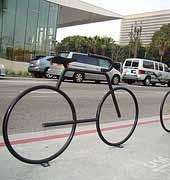
136 0
City of Oxnard Bicycle & Pedestrian Facilities Master Plan Appendices
 City of Oxnard Bicycle & Pedestrian Facilities Master Plan Appendices Approved by the City of Oxnard City Council February 2011 Prepared for: City of Oxnard Prepared by: Alta Planning + Design City of
City of Roseville Section 13 Design Standards. _Bikeways January 2016 SECTION 13 BIKEWAYS
 SECTION 13 BIKEWAYS 13-1 GENERAL The City of Roseville bikeway standards are designed to insure that transportation and recreational bikeways are constructed in a manner that would provide a safe and comfortable
4. TRAIL DESIGN GUIDELINES
 Trail Design Guidelines 4. TRAIL DESIGN GUIDELINES This chapter provides specific design guidelines for the Humboldt Bay Trail that are consistent with the guidelines currently observed in California and
General Design Factors
 Chapter 3: 3-1.0 Introduction General Design Factors Mn/DOT s goals include encouraging and accommodating safe bicycling. From a design perspective, these goals are achieved by first having an understanding
Appendix T CCMP TRAIL TRAFFIC & TRANSPORTATION DESIGN STANDARD
 Appendix T CCMP 3.3.4 TRAIL TRAFFIC & TRANSPORTATION DESIGN STANDARD 3.3.4 Trail Traffic and Transportation Design Multi-use trails have certain design standards, which vary depending on the agency that
Off-road Trails. Guidance
 Off-road Trails Off-road trails are shared use paths located on an independent alignment that provide two-way travel for people walking, bicycling, and other non-motorized users. Trails specifically along
Shared Use Path Design
 12B-2 Design Manual Chapter 12 - Sidewalks and Bicycle Facilities 12B - Bicycle Facilities Shared Use Path Design A. Accessible Shared Use Path Design 1. General: Applicable portions from the following
Off-Road Facilities Part 1: Shared Use Path Design
 Off-Road Facilities Part 1: Shared Use Path Design Presentation by: Eric Mongelli, P.E. Tom Huber October 9, 2012 FOLLOW THE CONVERSATION ON TWITTER Toole Design Group is live tweeting this webinar @tooledesign
Appendix 3 Roadway and Bike/Ped Design Standards
 Appendix 3 Roadway and Bike/Ped Design Standards OTO Transportation Plan 2040 4/20/2017 Page A3-1 Adopted Standards The adopted OTO Design Standards and Major Thoroughfare Plan are contained herein.
Chapter 4 On-Road Bikeways
 Chapter 4: 4-1.0 Introduction On-Road Bikeways This chapter provides guidelines to help select and design safe on-road bikeways. On-road bikeways include bicycle lanes, shared lanes, shoulders, and wide
Chapter 2: Standards for Access, Non-Motorized, and Transit
 Standards for Access, Non-Motorized, and Transit Chapter 2: Standards for Access, Non-Motorized, and Transit The Washtenaw County Access Management Plan was developed based on the analysis of existing
Active Transportation Facility Glossary
 Active Transportation Facility Glossary This document defines different active transportation facilities and suggests appropriate corridor types. Click on a facility type to jump to its definition. Bike
Chapter 3 DESIGN SPECIFICATIONS
 Brampton PathWays Planning and Design Guidelines 27 Chapter 3 DESIGN SPECIFICATIONS 3.1 CLASS 1 MULTI-USE PATH Off-road multi-use trails are the backbone of the Brampton PathWays Network. They are typically
Memorandum. Exhibit 60 SSDP To: Jenny Bailey, Senior Planner. From: Bill Schultheiss, P.E. (WA. P.E. #46108) Date: June 20, 2017
 Date: June 20, 2017") Memorandum To: Jenny Bailey, Senior Planner From: Bill Schultheiss, P.E. (WA. P.E. #46108) Date: June 20, 2017 Re: East Lake Sammamish Trail, Segment 2B Review King County has asked Toole Design Group
Memorandum To: Jenny Bailey, Senior Planner From: Bill Schultheiss, P.E. (WA. P.E. #46108) Date: June 20, 2017 Re: East Lake Sammamish Trail, Segment 2B Review King County has asked Toole Design Group
CURBSIDE ACTIVITY DESIGN
 5 CURBSIDE ACTIVITY DESIGN This chapter provides design guidance for separated bike lanes adjacent to curbside activities including parking, loading and bus stops. Typical configurations are presented
10.0 CURB EXTENSIONS GUIDELINE
 10.0 CURB EXTENSIONS GUIDELINE Road Engineering Design Guidelines Version 1.0 March 2017 City of Toronto, Transportation Services City of Toronto Page 0 Background In early 2014, Transportation Services
CHAPTER 1 STANDARD PRACTICES
 CHAPTER 1 STANDARD PRACTICES OBJECTIVES 1) Functions and Limitations 2) Standardization of Application 3) Materials 4) Colors 5) Widths and Patterns of Longitudinal Pavement Marking Lines 6) General Principles
INDEX. Geometric Design Guide for Canadian Roads INDEX
 Acceleration lane, see Lanes, Acceleration Access, 8.1 Access Management and Functional Classification 8.2 Access Management by Design Classification 8.3 Access Configuration 8.4 Building Set-Back Guidelines
Driveway Design Criteria
 Design Manual Chapter 5 - Roadway Design 5L - Access Management 5L-4 Driveway Design Criteria A. General For efficient and safe operations, access drives and minor public street intersections can be improved
Appendix B HDM CH 1000 BIKEWAY PLAN & DESIGN
 Appendix B HDM CH 1000 BIKEWAY PLAN & DESIGN HIGHWAY DESIGN MANUAL 1000-1 CHAPTER 1000 BIKEWAY PLANNING AND DESIGN Topic 1001 - General Criteria Index 1001.1 - Introduction The needs of non-motorized transportation
CHAPTER 16 PEDESTRIAN FACILITIES DESIGN AND TECHNICAL CRITERIA TABLE OF CONTENTS
 CHAPTER 16 PEDESTRIAN FACILITIES DESIGN AND TECHNICAL CRITERIA TABLE OF CONTENTS Section Title Page 16.1 General... 16-1 16.1.1 AASHTO Reference... 16-1 16.1.2 ADA Requirements... 16-1 16.2 Sidewalks...
5. RUNNINGWAY GUIDELINES
 5. RUNNINGWAY GUIDELINES These guidelines should be considered collectively when making runningway decisions. A runningway is the linear component of the transit system that forms the right-of-way reserved
700 Multi-Modal Considerations
 700 Multi-Modal Considerations Table of Contents 701 Railroads... 7-1 701.1 Background... 7-1 701.2 Crossing At-Grade... 7-1 701.2.1 General... 7-1 701.2.2 Railroad Parallel to Highway... 7-1 701.3 Lateral
Chapter 5 Shared-Use Paths
 Chapter 5: 5-1.0 Introduction Shared-Use Paths This chapter provides guidelines for design of bicycle transportation facilities that are separated from the roadway. In most cases, a path separated from
On Road Bikeways Part 1: Bicycle Lane Design
 On Road Bikeways Part 1: Bicycle Lane Design Presentation by: Nick Jackson Bill Schultheiss, P.E. September 04, 2012 FOLLOW THE CONVERSATION ON TWITTER Toole Design Group is live tweeting this webinar
DRAFT. Scholls Ferry Road Conceptual Design Plan Technical Memorandum Multi-Modal Examples. Multnomah County 1600 SE 190th Avenue Portland, OR 97233
 Technical Memorandum Multi-Modal Examples Prepared for 1600 SE 190th Avenue Portland, OR 97233 December 2008 CITATION This project is partially funded by a grant from the Transportation and Growth Management
DRAFT Montgomery County Bicycle Master Plan Design Toolkit
 DRAFT Montgomery County Bicycle Master Plan Design Toolkit Fall 2016 Sidepaths Sidepaths are shared use paths located parallel to and within the road right-of-way providing twoway travel for walking, bicycling,
Geometric Design Tables
 Design Manual Chapter 5 - Roadway Design 5C - Geometric Design Criteria 5C-1 Geometric Design Tables A. General The following sections present two sets of design criteria tables - Preferred Roadway Elements
Broad Street Bicycle Boulevard Design Guidelines
 Broad Street Bicycle Boulevard Design Guidelines Building from the strategies introduced in the 2013 Bicycle Transportation Plan and community input received thus far, City Transportation Staff have identified
Developed by: The American Traffic Safety Services Association (ATSSA) 15 Riverside Parkway, Suite 100 Fredericksburg, VA
 15 Riverside Parkway, Suite 100 Fredericksburg, VA") Addendum Developed by: The American Traffic Safety Services Association (ATSSA) 15 Riverside Parkway, Suite 100 Fredericksburg, VA 22406-1022 800-272-8772 This material is based upon work supported by
Addendum Developed by: The American Traffic Safety Services Association (ATSSA) 15 Riverside Parkway, Suite 100 Fredericksburg, VA 22406-1022 800-272-8772 This material is based upon work supported by
REGIONAL BICYCLE AND PEDESTRIAN DESIGN GUIDELINES
 REGIONAL BICYCLE AND PEDESTRIAN DESIGN GUIDELINES November 16, 2011 Deb Humphreys North Central Texas Council of Governments Bicycle and Pedestrian Advisory Committee Snapshot of the Guide 1. Introduction
Cycle Track Design Best Practices Cycle Track Sections
 Design Best Practices Sections It is along street segments where the separation and protection methods of cycle tracks offer more comfort than conventional bicycle lanes, and are more attractive to a wide
Designing On Road Bikeways
 Module B Learning Outcomes: Describe features of on road bikeways Select design criteria for on road bikeways in various contexts Bicycle Characteristics Height Handlebar 36 44 in Eye 60 in Operating 100
CHAPTER 6H. TYPICAL APPLICATIONS
 Section 6H.01 Typical Applications Support: CHAPTER 6H. TYPICAL APPLICATIONS Chapter 6G contains discussions of typical temporary traffic control activities. Chapter 6H presents typical applications for
Bowman-Melton Associates, Inc. june 2011
 2011 dallas bike plan ADDENDUM Bowman-Melton Associates, Inc. Complete Streets Initiative Design and policy guidance june 2011 2 2011 Dallas Bike Plan Complete Streets Initiative Design and Policy Guidance
October 2004 REVISIONS (2) SUPERELEVATION DEVELOPMENT 11.3(2)
 SUPERELEVATION DEVELOPMENT 11.3(2)") October 2004 REVISIONS (2) Chapter 11 HORIZONTAL ALIGNMENT SUPERELEVATION DEVELOPMENT 11.3(2) Chapter 12 VERTICAL ALIGNMENT VERTICAL CURVES PASSING SIGHT DISTANCE 12.5(2) VERTICAL CURVES STOPPING SIGHT
October 2004 REVISIONS (2) Chapter 11 HORIZONTAL ALIGNMENT SUPERELEVATION DEVELOPMENT 11.3(2) Chapter 12 VERTICAL ALIGNMENT VERTICAL CURVES PASSING SIGHT DISTANCE 12.5(2) VERTICAL CURVES STOPPING SIGHT
Access Location, Spacing, Turn Lanes, and Medians
 Design Manual Chapter 5 - Roadway Design 5L - Access Management 5L-3 Access Location, Spacing, Turn Lanes, and Medians This section addresses access location, spacing, turn lane and median needs, including
This page intentionally left blank.
 Appendix F. Design Guidelines County of Los Angeles Bicycle Master Plan This page intentionally left blank. F-2 Alta Planning + Design F Design Guidelines The County of Los Angeles works to implement on-and
Appendix C. Bicycle Route Signage
 Appendix C Bicycle Route Signage This page intentionally left blank. APPENDIX C - BICYCLE ROUTE AND WAYFINDING SIGNAGE Bicycle route signs are wayfinding signs that guide bicyclists along preferred, designated
WYDOT DESIGN GUIDES. Guide for. Non-NHS State Highways
 WYDOT DESIGN GUIDES Guide for Non-NHS State Highways 2014 GUIDE FOR Non-NATIONAL HIGHWAY SYSTEM (Non-NHS) STATE HIGHWAYS PRESERVATION REHABILITATION RECONSTRUCTION INTRODUCTION This Guide is directed to
CHAPTER 6H. TYPICAL APPLICATIONS
 2006 Edition Page 6H-1 CHAPTER 6H. TYPICAL APPLICATIONS Section 6H.01 Typical Applications Support: Whenever the acronym TTC is used in this Chapter, it refers to temporary traffic control. Standard: The
Who is Toole Design Group?
 2018 AASHTO Bike Guide Status Update NCHRP 15 60 Amalia Leighton Cody, PE, AICP & Kenneth Loen, PE Washington APWA October 4, 2018 Who is Toole Design Group? TDG is a full service engineering, planning
MUTCD Part 6G: Type of Temporary Traffic Control Zone Activities
 MUTCD Part 6G: Type of Temporary Traffic Control Zone Activities 6G.01 Typical Applications Each temporary traffic control (TTC) zone is different. Many variables, such as location of work, highway type,
American Railway Engineering and Maintenance of Way Association Letter Ballot. Draft
 American Railway Engineering and Maintenance of Way Association Letter Ballot 1. Committee and Subcommittee: Committee 5 Track Subcommittee 9 Road Crossings 2. Letter Ballot Number: 05-17-16 3. Assignment:
Alberta Infrastructure HIGHWAY GEOMETRIC DESIGN GUIDE AUGUST 1999
 Alberta Infrastructure HIGHWAY GEOMETRIC DESIGN GUIDE AUGUST 1999,1'(; A ACCELERATION Data on acceleration from stop D-29 Effects of grade D-35 Intersections D-97, D-99 Lanes D-97, F-5, F-7, F-15, F-21,
WYDOT DESIGN GUIDES. Guide for. NHS Arterial (Non-Interstate)
") WYDOT DESIGN GUIDES Guide for NHS Arterial (Non-Interstate) 2014 GUIDE FOR NATIONAL HIGHWAY SYSTEM (NHS) HIGHWAYS (NHS ARTERIALS, Non-Interstate) PRESERVATION REHABILITATION RECONSTRUCTION INTRODUCTION
WYDOT DESIGN GUIDES Guide for NHS Arterial (Non-Interstate) 2014 GUIDE FOR NATIONAL HIGHWAY SYSTEM (NHS) HIGHWAYS (NHS ARTERIALS, Non-Interstate) PRESERVATION REHABILITATION RECONSTRUCTION INTRODUCTION
CITY OF SARATOGA SPRINGS PEDESTRIAN CROSSING TOOLBOX
 CITY OF SARATOGA SPRINGS PEDESTRIAN CROSSING TOOLBOX This toolbox is to be used to guide pedestrian crossing improvements within the City of Saratoga Springs. Details for each crossing type are provided.
2.0 LANE WIDTHS GUIDELINE
 2.0 LANE WIDTHS GUIDELINE Road Engineering Design Guidelines Version 2.0.1 May 2018 City of Toronto, Transportation Services City of Toronto Page 0 Background In early 2014, Transportation Services initiated
Access Management Standards
 Access Management Standards Section 1: Application of Access Standards This chapter describes the Department's access management standards for access connections on the county roadway system. The standards
On-Street Bicycle Facilities
 On-Street Bicycle Facilities A. General 12B-3 Design Manual Chapter 12 - Sidewalks and Bicycle Facilities 12B - Bicycle Facilities Cyclists have similar access and mobility needs as other transportation
Appendix A: Crosswalk Policy
 Appendix A: Crosswalk Policy Appendix A: Crosswalk Policy Introduction This citywide Crosswalk Policy is aimed at improving pedestrian safety and enhancing pedestrian mobility by providing a framework
General References Definitions. (1) Design Guidance. (2) Supporting Information
 Design Guidance. (2) Supporting Information") Chapter 1240 Turning Roadways 1240.01 General 1240.02 References 1240.03 Definitions 1240.04 Turning Roadway Widths 1240.05 Documentation 1240.01 General The roadway on a curve may need to be widened to
Chapter 1240 Turning Roadways 1240.01 General 1240.02 References 1240.03 Definitions 1240.04 Turning Roadway Widths 1240.05 Documentation 1240.01 General The roadway on a curve may need to be widened to
The 2012 AASHTO Bike Guide: An Overview
 The 2012 AASHTO Bike Guide: An Overview Presentation by: Jennifer Toole, AICP, ASLA Peter Lagerwey August 10, 2012 {Enter Module Name on Master Slide} WEBINAR #1: OVERVIEW OF 2012 AASHTO BIKE GUIDE Today
OBJECTIVE: Improve safety by designing all bicycle facilities to the latest AASHTO bicycle guidelines and 2009 MUTCD Standards.
 DESIGN AND APPLICATION OF GUIDELINES AND STANDARDS The Citizen Advisory and Technical Advisory Committees identified improving safety by providing consistent bicycle facilities throughout the region as
Figure 3B-1. Examples of Two-Lane, Two-Way Marking Applications
 Figure 3B-1. Examples of Two-Lane, Two-Way Marking Applications A - Typical two-lane, two-way marking with passing permitted in both directions B - Typical two-lane, two-way marking with no-passing zones
ROUNDABOUTS/TRAFFIC CIRCLES
 GENERAL 1. Description This standard identifies minimum requirements that shall be met for Roundabouts and Neighborhood Traffic Circles in the design and construction of elements for Arlington County Horizontal
G AT E WAY PLAN. Community BRIEFING KIT GATEWAY BIKE
 G AT E WAY PLAN GATEWAY BIKE Community BRIEFING KIT PLAN August 2016 TABLE OF CONTENTS INTRODUCTION... 1 THE BENEFITS OF A BIKEABLE COMMUNITY... 2 ECONOMY...2 SAFETY...3 HEALTH...3 HOUSEHOLD SPENDING...3
Figure 1: Graphical definitions of superelevation in terms for a two lane roadway.
 Iowa Department of Transportation Office of Design Superelevation 2A-2 Design Manual Chapter 2 Alignments Originally Issued: 12-31-97 Revised: 12-10-10 Superelevation is the banking of the roadway along
3-13 UFC - GENERAL PROVISIONS AND GEOMETRIC DESIGN FOR ROADS, STREETS, WALKS, AND OPEN
 maintenance, and erosion. Stability is required to maintain the integrity of the pavement structure, and a slope stability analysis should be conducted for cuts and fills greater than 15 feet. For lower
SECTION 3 STREET DESIGN
 3.01 GENERAL SECTION 3 STREET DESIGN For purposes of geometric and structural design, streets shall be classified according to the following table. The City Engineer will determine the class of all proposed
GENERAL. 1. Description
 GENERAL 1. Description This standard identifies minimum requirements that shall be met for all Bus Stops in the design and construction of elements for Arlington County Horizontal Design Standards. This
2012 by the American Association of State Highway and Transportation Officials. All rights reserved. Duplication is a violation of applicable law.
 Table of Contents Chapter 1: Introduction... 1-1 1.1 Design Imperative... 1-1 1.2 Purpose... 1-1 1.3 Scope... 1-2 1.4 Definitions... 1-2 Chapter 2: Bicycle Planning... 2-1 2.1 Background... 2-1 2.2 Why
APPENDIX A: Complete Streets Checklist DRAFT NOVEMBER 2016
 APPENDIX A: Complete Streets Checklist DRAFT NOVEMBER 2016 Complete Streets Checklist MetroPlan Orlando s Complete Streets Checklist is an internal planning tool for staff to further implementation of
TRAFFIC CALMING GUIDE FOR TORONTO CITY OF TORONTO TRANSPORTATION SERVICES DIVISION
 TRAFFIC CALMING GUIDE FOR TORONTO CITY OF TORONTO TRANSPORTATION SERVICES DIVISION CITY OF TORONTO TRANSPORTATION SERVICES DIVISION 2016 TRAFFIC CALMING GUIDE FOR TORONTO TABLE OF CONTENTS Introduction
Toronto Complete Streets Guidelines
 88 90 5.1 Cycling Design Principles 92 5.2 Context-sensitive Cycling Facilities 96 5.3 Key Cycling Elements Cycling infrastructure provides choice in how people are able to move around the city. Cyclists
Access Management in the Vicinity of Intersections
 Access Management in the Vicinity of Intersections FHWA-SA-10-002 Technical Summary Photo: Ralph Bentley (used with permission) 0 Access Management is: The design, implementation and management of entry
PLACEMENT OF SIGNS RECOMMENDED PRACTICES SUB-SECTION
 Page 1 of 6 RECOMMENDED PRACTICES PART SECTION SUB-SECTION HIGHWAY SIGNS GENERAL General Proper positioning of signs is an important element in the overall control of traffic within a roadway network.
Report. Typical Sections. City of Middleton, WI
 Report Typical Sections City of Middleton, WI December 2006 Report for City of Middleton, Wisconsin Typical Sections repared by: Traffic Associates LLC and STRAND ASSOCIATES, INC. 910 West Wingra Drive
Appendix C. TRAFFIC CALMING PROGRAM TOOLBOX
 Appendix C. TRAFFIC CALMING PROGRAM TOOLBOX PHASE I...2 Do Not Enter Sign...3 One-Way Sign...4 Turn Prohibition...5 Pavement Markings...6 Speed Monitoring Trailer...7 Neighborhood Speed Watch...8 Police
EUCLID AVENUE PARKING STUDY CITY OF SYRACUSE, ONONDAGA COUNTY, NEW YORK
 EUCLID AVENUE PARKING STUDY CITY OF SYRACUSE, ONONDAGA COUNTY, NEW YORK CITY OF SYRACUSE DEPARTMENT OF PUBLIC WORKS 1200 CANAL STREET EXTENSION SYRACUSE, NEW YORK 13210 DRAFT REPORT DATE: November 13,
Table of Contents. Introduction. Prompt List Arterials and Streets. Prompt List Interchange. Prompt List Intersections. Prompt List Limited Access
 Table of Contents Introduction Prompt List Arterials and Streets Prompt List Interchange Prompt List Intersections Prompt List Limited Access Prompt List MOT Prompt List Pedestrian Bicyclist Prompt List
CHAPTER 2G. PREFERENTIAL AND MANAGED LANE SIGNS
 2011 Edition - Revision 2 Page 275 Section 2G.01 Scope CHAPTER 2G. PREFERENTIAL AND MANAGED LANE SIGNS 01 Preferential lanes are lanes designated for special traffic uses such as high-occupancy vehicles
Appendix A: Facility Design Guidelines
 Appendix A: Facility Design Guidelines CONNECTING OUR COMMUNITY TABLE OF CONTENTS Chapter One: Introduction and Background, p. A-1 National Guidelines, p. A-2 Local Guidelines, p. A-3 Chapter Two: User
St. Francis Drive through the City of Santa Fe Corridor Study
 VII. ENGINEERING AND ENVIRONMENTAL EVALUATION TRAIL CONNECTIVITY In the southern portion of the Corridor there is a lack of a sidewalk, trail or bicycle facility within the right-ofway. However, the City
Considerations in the Review and Approval of a Driveway in Your Jurisdiction
 Considerations in the Review and Approval of a Driveway in Your Jurisdiction So, are you the person at your agency who reviews and approves new driveways? Or, perhaps you are part of the TEAM of people
Guidance. ATTACHMENT F: Draft Additional Pages for Bicycle Facility Design Toolkit Separated Bike Lanes: Two-Way to One-Way Transitions
 ATTACHMENT F: Draft Additional Pages for Bicycle Facility Design Toolkit Separated Bike Lanes: Two-Way to One-Way Transitions This treatment provides a transition from two-way separated bike lanes to one-way
Agenda. Overview PRINCE GEORGE S PLAZA METRO AREA PEDESTRIAN PLAN
 PRINCE GEORGE S PLAZA METRO AREA PEDESTRIAN PLAN May 28, 2008 Agenda Welcome and introductions Project overview and issue identification Planning context and strengths Design challenges and initial recommendations
MARTIN LUTHER KING JR. WAY
 OCTOBER 2011 40 Vision and Goals The Martin Luther King, Jr. Way Illustrative Master Plan that follows has been developed through a process of community involvement. It expresses a long term vision for
Accommodating Pedestrians in the Work Zone
 Accommodating Pedestrians in the Work Zone Guidance for Section C Plan Preparers Some impacts cannot be avoided and those impacts apply to residents, businesses, motorists, and pedestrians alike. However,
Section 9A.07 Meaning of Standard, Guidance, Option, and Support
 2012 Edition Page 895 PART 9. TRAFFIC CONTROLS FOR BICYCLE FACILITIES CHAPTER 9A. GENERAL Section 9A.01 Requirements for Bicyclist Traffic Control Devices 01 General information and definitions concerning
Recommended Roadway Plan Section 2 - Land Development and Roadway Access
 Recommended Roadway Plan Section 2 - Land Development and Roadway Access SECTION 2 Land Development and Roadway Access 2.1 Land Use and Access Management The Federal Highway Administration (FHWA) defines
INTRODUCTION. Intersections Treatments
 Table of Contents Introduction Bikeway Facility Types Off-Street Trails Stream Valley Park Trails Sidepaths Separated Bike Lanes Buffered Bike Lanes Conventional Bike Lanes Advisory Bike Lanes Bikeable
Chapter 5: Crossing the Street
 Chapter 5: Crossing the Street Whether walking or bicycling, a student s journey to school will more than likely require crossing one or more streets. Per the Safe Routes to School Guide, maintained by
ACTIVE TRANSPORTATION
 ACTIVE TRANSPORTATION Mobility 2040 Supported Goals Improve the availability of transportation options for people and goods. Support travel efficiency measures and system enhancements targeted at congestion
March 2008 FINAL DRAFT. Supplemental Bikeway Design Guidelines
 March 2008 FINAL DRAFT Supplemental Bikeway Design Guidelines Prepared for: Marin County Department of Public Works Marin County Unincorporated Area Bicycle and Pedestrian Master Plan Prepared by: Alta
SECTION TRAFFIC REGULATIONS
 SECTION 01550 TRAFFIC REGULATIONS PART 1 - GENERAL 1.01 OBJECTIVES A. The Contractor shall provide for safe movement of vehicular, bicycle and pedestrian traffic, including persons with disabilities in
Section 3A.04 Colors. Section 3B.10 Approach Markings for Obstructions
 Section 3A.04 Colors Markings shall be yellow, white, red, or blue, or purple. The colors for markings shall conform to the standard highway colors. Black in conjunction with one of the above colors shall
INTERSECTIONS AT GRADE INTERSECTIONS
 INTERSECTIONS 1 AT GRADE INTERSECTIONS INTERSECTIONS INTERSECTIONS = INTERRUPTED FACILITIES Definitions and key elements An intersection is defined as an area where two or more roadways join or cross.
Bicycle Paths Chapter 4
 Bicycle Paths Bicycle Paths Bicycle paths consist of multiple use paths or trails, separated from motorized vehicular traffic, on which bicycle travel is anticipated and permitted. Bicycle paths may be
ADA on Construction. Guidance for Section C Plan Preparers
 ADA on Construction Guidance for Section C Plan Preparers Some impacts cannot be avoided and those impacts apply to residents, businesses, motorists, and pedestrians alike. However, good planning can minimize
Roadway Design Manual
 Roadway Design Manual Manual Notice Archive by Texas Department of Transportation (512) 302-2453 all rights reserved Manual Notice 2009-1 From: Manual: Mark A. Marek, P.E Roadway Design Manual Effective
Washington St. Corridor Study
 FIGURE 7.17 Bridge Alternatives - Cross Sections 86 Discarded Alternative: Short-Term Bridge Repair Short-term repairs and west bridge span replacement were considered during analysis. Short-term repairs
MUTCD Part 6: Temporary Traffic Control
 MUTCD Part 6: Temporary Traffic Control OMUTCD English units are preferred. OHIO MANUAL OF UNIFORM TRAFFIC CONTROL DEVICES TABLE OF CONTENTS PREFACE INTRODUCTION TABLE OF CONTENTS PART 1. GENERAL Chapter
SECTION 1A NEW JERSEY TURNPIKE GEOMETRIC DESIGN
 SECTION 1A NEW JERSEY TURNPIKE GEOMETRIC DESIGN Table of Contents Page No 1A.1 GENERAL...1 1A.1.1 DESIGN CONTROLS...1 1A.2 MAINLINE ROADWAYS...4 1A.2.1 ROADWAY DESIGNATION...4 1A.2.2 DESIGN SPEED...4 1A.2.3
Planning Guidance in the 2012 AASHTO Bike Guide
 Planning Guidance in the 2012 AASHTO Bike Guide Presentation by: RJ Eldridge Peter Lagerwey August 22, 2012 WEBINAR 2: PLANNING GUIDANCE IN THE 2012 AASHTO BIKE GUIDE Today s Webinar Significant Updates
ATTACHMENT NO. 11. RRLRT No. 2. Railroad / Light Rail Transit Technical Committee TECHNICAL COMMITTEE: Busway Grade Crossings STATUS/DATE OF ACTION
 ATTACHMENT NO. 11 RRLRT No. 2 TECHNICAL COMMITTEE: TOPIC: Railroad / Light Rail Transit Technical Committee Busway Grade Crossings STATUS/DATE OF ACTION RRLRT TC Draft: 06/23/2011 RRLRT TC Approval: 06/27/2014
This Chapter sets forth the minimum design, technical criteria and specifications to be used in the preparation of all roadway plans.
 4.1 GENERAL This Chapter sets forth the minimum design, technical criteria and specifications to be used in the preparation of all roadway plans. These Roadway Standards are for new construction and modification
Town of Mooresville, North Carolina Neighborhood Traffic Calming and Control Device Policy
 Town of Mooresville, North Carolina Neighborhood Traffic Calming and Control Device Policy Adopted January 6, 2014 Town of Mooresville Development Services Department TOWN OF MOORESVILLE NEIGHBORHOOD TRAFFIC
Chapter 3 - Local Urban Road System CHAPTER 3 LOCAL URBAN ROAD SYSTEM
 CHAPTER 3 LOCAL URBAN ROAD SYSTEM 3.0 INTRODUCTION As in Chapter 2 for the local rural road system, the local urban road system also utilizes the concepts of land use context, functional classification
Design Overview. Section 4 Standard Plans for Design. Pedestrian Access Routes. Pedestrian Access Routes. Overview. Cross Slope
 Design Overview Section 4 Standard Plans for Design Fall, 2017 Ann Johnson, PE Services Brady Rutman, SRF Consulting Group Overview Design Basics Recommendations: The Zone System Driveway Crossings Pedestrian