400 Intersection Design
|
|
|
- Jade Bruce
- 5 years ago
- Views:
Transcription
1 400 Intersection Design Table of Contents 401 Intersections At-Grade Intersection Locations Intersection Traffic Control and Operational Analysis Signals Stop Control Roundabouts Crossroad Alignment Crossroad Profile Intersection Area Drainage Profile at Stop Intersections Profile at Signalized Intersections Approach Radii Rural Urban Curbed to Uncurbed Transitions Approach Lanes Left Turn Lanes Double Left Turn Lanes Right Turn Lanes Double Right Turn Lanes Additional Through Lanes Recovery Area at Curbed Intersections Islands Characteristics Channelizing Islands Island Treatments Curbed Islands Painted Islands Nonpaved Islands Designing Roadways to Accommodate Pedestrians Curb Radii Crossing Distance Considerations Crossing Islands and Medians Turning Movements Two Way Left Turn Lanes (TWLTL) General TWLTL Justification TWLTL Design Reversible Lanes Roundabouts General Roundabout Consideration Operational Analysis Geometric Design Design Process Design Vehicle Inscribed Diameter July 2018
2 400 Intersection Design Entry and Exit Widths Development of Entry Widths for Multilane Roundabouts Exit Width Reduction of Multilane Roundabouts Circulatory Roadway Truck Apron Gore Striping Right-Turn Bypass Lanes Cross Slopes Splitter Islands List of Figures July 2018
3 400 Intersection Design 401 Intersections At-Grade Intersection Locations Care should be taken in locating new at-grade intersections. The alignment and grade on the mainline roadway should, as a minimum, provide stopping sight distance as discussed in Section The criteria for intersection sight distance (see Section 201.3) should also be met wherever possible. It is best to avoid locating an intersection on a curve. Since this is often impossible, it is recommended that intersection sites be selected where the curve superelevation is 0.04 or less. It is also recommended that intersections be located where the grade on the mainline roadway is 6 percent or less, with 3 percent being the desirable maximum Intersection Traffic Control and Operational Analysis The type of traffic control at intersections directly affects the geometric design. An early determination of the type of intersection control must be made (i.e. stop signs, signal, or roundabout). Whenever there is doubt as to the adequacy of stop control during the design life of the project, traffic signal warrants, as outlined in the Ohio Manual of Uniform Traffic Control Devices (OMUTCD) should be investigated. Intersection capacity analysis procedures of the current edition of the Highway Capacity Manual shall be used to determine the number and type of lanes at intersections. Intersections shall be analyzed and designed to accommodate traffic volumes as per Section Analyses shall be performed using Highway Capacity Software (HCS). Other software may be used to supplement the HCS analysis, depending upon intersection type. Refer to Figures a thru c for software guidance Signals In general, when performing capacity analysis of signalized intersections, the critical (worst) delay of the north/south approach should approximately equal the worst delay of the east/west approach. Approach delays are considered balanced when they are within 3 seconds. Additionally, the highest control delays should be balanced, preferably within 5 seconds. When intersections are severely over capacity, balancing the approach and control delays may not be feasible; however, the critical delays should be as close as practical. This methodology provides a common basis for comparison between the no-build and build alternatives and is not meant to provide a signal timing plan for daily operations. This methodology defines the intersection size in consideration of the 20 year design. Determination of the necessary number and type of lanes for the build condition is based upon a signal design where all individual lane v/c ratios are less than 1.0, and preferably less than Stop Control For stop controlled intersections, where signal warrants are not anticipated to be met by the design year or would not be installed due to access management controls, Figures 401-5a thru 401-6d are provided to determine the need for turn lanes. The stopped approaches may be evaluated using HCS to determine the necessary number and type of lanes to improve the Levels of Service. July
4 400 Intersection Design Roundabouts Roundabouts shall be analyzed using HCS or SIDRA. Turn lane lengths for the approach lanes of the roundabout shall be determined by accommodating the 95 th percentile queue lengths as identified by HCS or SIDRA. Refer to Figures a thru c for software guidance. While it is important to plan for future traffic volumes and capacity needs, the immediate effects on users should also be considered including costs. A roundabout constructed with a wide cross section (multilane) can negatively impact user (pedestrian, bicycle, unfamiliar drivers) movements. Therefore, a phased implementation on multilane roundabouts is required if the single lane construction of the roundabout can meet acceptable levels of service based on opening day traffic. The phased implementation should be based on the available and future funding resources and location (rural or urban, drivers familiar or unfamiliar). The current users needs will be accommodated while still providing an opportunity for the roundabout to be expected for future traffic volume growth. When using a phased approach, it is important to design the full build layout footprint to ensure right-of-way is secured for future planned improvements. It is also beneficial to plan the construction of the roundabout to potentially allow for easier expansion in the future Crossroad Alignment Intersection angles of 70 degrees to 90 degrees are to be provided on all new or relocated highways. An angle of 60 degrees may be satisfactory if: (1) the intersection is signalized; or (2) the intersection is skewed such that a driver stopped on the side road has the acute angle (at center of intersection) on his left side (vision not blocked by his own vehicle). Relocation of the crossroad is often required to meet the desired intersection location, to avoid steep crossroad profile grades and to adjust intersection angles. Horizontal curves on crossroads should be designed to meet the design speed of the crossroad. The crossroad alignment should be as straight as possible. Figure shows an example of a crossroad relocation. Both curve 1 and curve 3 may be reduced per the figure Crossroad Profile Intersection Area The portion of the intersection located within 60 ft. of the mainline edge of traveled way, measured along the crossroad centerline, is considered to be the "intersection area". The pavement surface within this "intersection area" should be visible to drivers within the limits of the minimum stopping sight distance shown on Figure By being able to see the pavement surface (height of object of 0), drivers (height of eye of 3.5 ft.) will be able to observe the radius returns, pavement markings, and recognize that they are approaching an intersection. Figure shows the "intersection area". Combinations of pavement cross slopes and profile grades may produce unacceptable edge of traveled way profiles in the "intersection area". For this reason, edge of traveled way profiles should be plotted and graphically graded to provide a smooth profile. July
5 400 Intersection Design Drainage Within the intersection area, the profile of the crossroad should be sloped wherever possible so the drainage from the crossroad will not flow across the through road pavement. For a stop condition, the 10 ft. of crossroad profile adjacent to the through pavement is normally sloped away from the through pavement, using at least a 1.6 percent grade, as shown on Figure Profile at Stop Intersections Profile grades within the "intersection area" for stop conditions are shown in Figures and The grade outside the "intersection area" is controlled by the design speed of the crossroad. Normal design practices can be used outside the "intersection area" with the only restriction on the profile being the sight distance required in Section Grade breaks are permitted at the mainline edge of traveled way for a stop condition as discussed in Note 3 of Figure If these grade breaks are exceeded, they should be treated according to Note 3 on Figure Several examples are shown on Figure of the use of grade breaks or short vertical curves adjacent to the mainline edge of traveled way Profile at Signalized Intersections Signalized intersections require a more sophisticated crossroad profile. Whenever possible, profiles through the intersection area of a signalized intersection should be designed to meet the design speed of the crossroad. Figure shows three examples of crossroad profiles at intersections. On Examples A and B (Figure 401-4), the mainline cross slopes will need to be adjusted to match the crossroad profile within the intersection area. Grade breaks shown on Examples A and C should be in accordance with Section Since the grade break across a normal crowned pavement is 3.2 percent, it should be noted that the crown must be flattened (See Example C). This will allow vehicles on the crossroad to pass through the intersection on a green signal safely without significantly adjusting their speed. The sight distance requirements of Section within the "intersection area" are also applicable for signalized intersections Approach Radii Rural Approach radii in rural areas shall normally be 50 ft., except that radii less than 50 ft. (minimum 35 ft.) may be used at minor intersecting roads if judged appropriate for the volume and character of turning vehicles. Radii larger than 50 ft., a radius with a taper, or a three center curve, should be used at any intersection where the design must routinely accommodate semi-trailer truck turning movements. Truck turning templates should be used to determine proper radii and stop bar location. When truck turning templates are used, a 2 foot clearance should be provided between the edge of traveled way and the closest tire path. Normally the approach width at the ends of the radius returns should be 24 ft. The pavement width shall be tapered back to the normal pavement width at a rate of 10:1 if the taper is adjacent to the radius returns. July
6 400 Intersection Design Urban Corner radii at street intersections should consider the right of way available, the intersection angle, pedestrian traffic, approach width and number of lanes. The following should be used as a guide: 15 to 25 ft. radii are adequate for passenger vehicles and may be provided at minor cross streets where there are few trucks or at major intersections where there are parking lanes. 25 ft. or more radii should be provided at minor intersections on new or reconstruction projects where space permits. 30 ft. radii or more should be used where feasible at major cross street intersections. Radii of 40 ft. or more, three-centered compound curves or simple curves with tapers to fit truck paths should be provided at intersections used frequently by buses or large trucks Curbed to Uncurbed Transitions Figures 401-4a and 401-4b show acceptable methods to transition from curbed to uncurbed roadways at intersections. Figure 401-4a shows two options to transition from an uncurbed mainline roadway to a curbed approach roadway. Figure 401-4b shows the transition from a curbed mainline roadway to an uncurbed approach roadway. See Section for additional information Approach Lanes Left Turn Lanes Probably the single item having the most influence on intersection operation is the treatment of left turn vehicles. Left turn lanes are generally desirable at most intersections. However, cost and space requirements do not permit their inclusion in all situations. Intersection capacity analysis procedures of the current edition of the Highway Capacity Manual should be used to determine the number and use of left turn lanes. For unsignalized intersections, left turn lanes may also be needed if they meet warrants as provided in Figures 401-5a, 401-5b, and 401-5c. The warrants apply only to the free-flow approach of the unsignalized intersection. Refer to Section and Figures a thru c for analysis criteria and software guidance. Left turn lanes should be placed opposite each other on opposing approaches to enhance sight distance. They are developed in several ways depending on the available width. The first example on Figure shows the development required when additional width must be generated. The additional width is normally accomplished by widening on both sides. However, it could be done all on one side or the other. In the second example on Figure 401-7, the median width is sufficient to permit the development of the left turn lane. Figure shows the condition where an offset left turn lane is required to obtain adequate sight distance in wide medians. In developing turn lanes, several types of tapers may be involved as shown in Figure Approach Taper - An approach taper directs through traffic to the right. Approach taper lengths are calculated using the following: July
7 400 Intersection Design Design Speed of 50 mph or more: L=WS Design speed less than 50 mph: L=WS 2 /60 Where: L = Approach taper length in feet W = Offset width in feet S = Design Speed 2.. Departure Taper - The departure taper directs through traffic to the left. Its length should not be less than that calculated using the approach taper equations. Normally, however, the departure taper begins opposite the beginning of the full width turn lane and continues to a point opposite the beginning of the approach taper. 3. Diverging Taper - The diverging taper is the taper used at the beginning of the turn lane. The recommended length of a diverging taper is 50 ft.. Figures and have been included to aid in determining the required lengths of left turn lanes at intersections. An example problem that illustrates the use of these figures is included along with the figures. After determining the length of a left turn lane, the designer should also check the length of storage available in the adjacent through lane(s) to assure that access to the turn lane is not blocked by a backup in the through lane(s). To do this, Figure may be entered using the average number of through vehicles per cycle, and the required length read directly from the table. If two or more lanes are provided for the through movement, the length obtained should be divided by the number of through lanes to determine the required storage length. It is recommended that left turn lanes be at least 100 ft. long, and the maximum storage length be no more than 600 ft. The width of a left turn lane should desirably be the same as the normal lane widths for the facility. A minimum width of 11 ft. may be used in moderate and high speed areas, while 10 ft. may be provided in low speed areas. Additional width should be provided whenever the lane is adjacent to a curbed median as discussed in Section Double Left Turn Lanes Double left turn lanes should be considered at any signalized intersection with left turn demands of 300 vehicles per hour or more. The actual need shall be determined by performing a signalized intersection capacity analysis. Refer to Section and Figures a thru c for analysis criteria and software guidance. Fully protected signal phasing is required for double left turns. When the signal phasing permits simultaneous left turns from opposing approaches, it may be necessary to laterally offset the double left turn lanes on one approach from the left turn lane(s) on the opposing approach to avoid conflicts in turning paths. All turning paths of double left turn lanes should be checked with truck turning templates allowing 2 ft. between the tire path and edge of each lane. Expanded throat widths are necessary for double left turn lanes. For details on double left turn lanes, see Figures and July
8 400 Intersection Design Right Turn Lanes Exclusive right turn lanes are less critical in terms of safety than left turn lanes. Right turn lanes can significantly improve the level of service of signalized intersections. They also provide a means of safe deceleration for right turning traffic on high-speed facilities and separate right-turning traffic at stopcontrolled intersections. To determine the need for right turn lanes, intersection capacity analysis procedures of the current edition of the Highway Capacity Manual should be used. For unsignalized intersections, right turn lanes may also be needed if they meet warrants as provided in Figures 401-6a, 401-6b, 401-6c and 401-6d. The warrants apply only to the free-flow approach of the unsignalized intersecton. Refer to Section and Figures a thru c for analysis criteria and software guidance. Figure shows the design of right turn lanes. Figure may be used in preliminary design to estimate the storage required at signalized intersections. The recommended maximum length of right turn lanes at signalized intersections is 800 ft., with 100 ft. being the minimum length. The blockage of the right turn lane by the through vehicles should also be checked using Figure With right-turn-on-red operation, it is imperative that access to the right turn lane be provided to achieve full utilization of the benefits of this type of operation. The width of right turn lanes should desirably be equal to the normal through lane width for the facility. In low speed areas, a minimum width of 10 ft. may be provided. Additional lane width should be provided when the right turn lane is adjacent to a curb Double Right Turn Lanes Double right turn lanes are rarely used. When they are justified, it is generally at an intersection involving either an off-ramp or a one-way street. Double right turn lanes require a larger intersection radius (usually 75 ft. or more) and a throat width comparable to a double left turn (See Section and Figure ) Additional Through Lanes Normally the number of through lanes at an intersection is consistent with the number of lanes on the basic facility. Occasionally, through lanes are added on the approach to enhance signal design. As a general suggestion, enough main roadway lanes should be provided so that the total through plus turn volumes does not exceed 450 vehicles per hour per lane. See Figure Recovery Area at Curbed Intersections When a through lane becomes a right turn lane at a curbed intersection, an opposite-side tapered recovery area should be considered. The taper should be long enough to allow a trapped vehicle to escape, but not so long as to appear like a merging lane. See Figure July
9 400 Intersection Design Islands Characteristics An island is a defined area between traffic lanes used for control of vehicle movement. Islands also provide an area for pedestrian refuge and traffic control devices. Islands serve three primary functions: (1) to control and direct traffic movement, usually turning; (2) to divide opposing or same direction traffic streams usually through movements; and (3) to provide refuge for pedestrians. Most islands combine functions. Although certain situations require the use of islands, they should be used sparingly and avoided wherever possible Channelizing Islands Channelizing islands control and direct traffic into the proper paths for the intended use and are an important part of intersection design. They may be of many shapes and sizes, depending on the conditions and dimensions of the intersection. A common form is the corner triangular shape that separates right turning traffic from through traffic. Figures a, b, c and d detail Channelizing Island designs for various vehicle combinations. Channelizing Islands are used at intersections for the following reasons: Separation of conflicts. Control of angle of conflict. Reduction in excessive pavement areas. Indication of proper use of intersection Favor a predominant turning movement. Pedestrian protection. Protection and storage of vehicles. Location of traffic control devices. These islands should be placed so that the proper course of travel is immediately obvious and easy for the driver to follow. Care should be given to the design when the island is on or beyond a crest of a vertical curve, or where there is a substantial horizontal curvature on the approach to or through the channelized area. Properly placed islands are advantageous where through and turning movements are heavy Island Treatments July
10 400 Intersection Design Curbed Islands Curbed islands are most often used in urban areas where traffic is moving at relatively low speeds (less than 50 mph. The smallest curbed island that should normally be considered is 50 sq. ft. in an urban area and 75 sq. ft. if used in a rural area. A 100 sq. ft. island is preferred in either case. Curb Islands are sometimes difficult to see at night, so the intersection should have fixed source lighting Painted Islands Islands delineated by pavement markings are often preferred in rural or lightly developed areas, when approach speeds are relatively high, where there is little pedestrian traffic, where fixed-source lighting is not provided, or where traffic control devices are not located within the island Nonpaved Islands Nonpaved islands are normally used in rural areas. They are generally turf and are depressed for drainage purposes Designing Roadways to Accommodate Pedestrians Designing a roadway that successfully meets the needs of both vehicular traffic and pedestrians can be a challenging task. Basic roadway design parameters such as roadway widths, corner turning radii and sight distances affect the ability of that roadway to accommodate pedestrians. For example, the wider the roadway, the more difficult it is for pedestrians to cross, and the greater the barrier effect of this roadway on the communities through which it passes. Undivided six-lane arterials, with or without parking, are not usually pedestrian friendly, while eight and ten-lane arterials create an even more formidable barrier. The size of a corner radius can also have a significant effect on the overall operation and safety of an intersection. Large corner turning radii promote higher turning speeds, as well as increasing the pedestrian crossing distance and exposure time. Large curb radii also reduce the space for pedestrians waiting to cross, move pedestrians out of the turning motorists= line of sight, and make it harder for the pedestrian to see turning cars. However, in some cases, corners with small turning radii can impact the overall operating efficiency of an arterial intersection, as well as cause the curb to be hit by a turning vehicle. The designer must keep in mind that, as important as it is for the motorist to see everything adjacent to the roadway, it is of equal importance for the pedestrian, particularly children and wheelchair users, to be able to view and react to potential conflicts. At no area is this issue more critical than at crosswalk locations. Vehicles parked near crosswalks can create a sight distance problem. July
11 400 Intersection Design Curb Radii The radius used at urban and suburban locations at both signalized and unsignalized intersections, where there may be pedestrian conflicts, must consider the safety and convenience aspects of both the motorist and pedestrian. The radius should be the smallest possible for the circumstances rather than design for the largest possible design vehicle, which often accounts for less than 2 percent of the total users. A large radius can increase the speed of turning motorists and the crossing distance for pedestrians, creating increased exposure risks. Two distinct radii need to be considered when designing street corners. The first is the radius of the street corner itself, and the second is the effective turning radius of the selected design vehicle. The effective turning radius is the radius needed for a turning vehicle to clear any adjacent parking lanes and/or to align itself with its new travel lane. Using an effective turning radius allows a smaller curb radius than would be required for the motorist to turn from curb lane to curb lane. Parking lanes should end at least 20 ft. in advance of the intersection Crossing Distance Considerations Short crosswalks help pedestrians cross streets. Excessive crossing distances increase the pedestrian exposure time, increase the potential of vehicle-pedestrian conflict, and add to vehicle delay. Curb extensions reduce the crossing distance and improve the sight distances for both the vehicle and the pedestrian. In general, curb extensions should extend the width of the parking lane, approximately 6 ft. from the curb for a minimum length of 20 ft Crossing Islands and Medians Where a wide intersection cannot be designed or timed to accommodate all the pedestrian crossing needs across one leg of the intersection at one time, a median or crossing island (often referred to as a refuge island) should be considered. Medians are raised or painted longitudinal spaces. Triangular channelization islands adjacent to right turning lanes can also act as crossing islands. Desirably, crossing islands should be at least 5 ft. wide. A width of 8 ft. is needed to accommodate bicycles, wheelchairs, scooters and groups of pedestrians. Crossing island width should be a minimum of 8 ft. on roadways with speeds of 50 mph or greater Turning Movements At both signalized and unsignalized intersections, steps should be taken to ensure that turning speeds are kept low and that sight distance is not compromised for either the motorist or pedestrian. July
12 400 Intersection Design 402 Two Way Left Turn Lanes (TWLTL) General Midblock left turns are often a serious problem in urban and suburban areas. They can be a safety problem due to angle accidents with opposing traffic as well as rear end accidents with traffic in the same direction. Midblock left turns also restrict capacity. Two way left turn lanes (TWLTL) have proven to be a safe and cost-effective solution to this problem TWLTL Justification TWLTL should be considered whenever actual or potential midblock conflicts occur. This is particularly true when accident data indicates a history of midblock left turn related accidents. Closely spaced driveways, strip commercial development or multiple-unit residential land use along the corridor are other indicators of the possible need for a TWLTL. Some guidelines which may be used to justify the use of TWLTL are listed below: 1. 10,000 to 20,000 vehicles per day for four lane highways. 2. 5,000 to 12,000 vehicles per day for two lane highways midblock turns per 1000 ft. during peak hour. 4. Left turn peak hour volume 20 percent or more of total volume. 5. Minimum reasonable length of 1000 ft. or two blocks TWLTL Design Widths for TWLTL are preferably the same as through lane widths (See Section ). A 10 ft. lane may be used in restricted areas. Care should be taken not to make a TWLTL wider than 14 ft. since this may encourage shared side-by-side use of the lane. TWLTL markings shall be in accordance with the OMUTCD. See Section for location of the crown point Reversible Lanes A reversible lane is a lane on which the direction of traffic flow can be changed to utilize maximum roadway capacity during peak demand periods. Reverse-flow operation on undivided streets generally is justified where 65 percent or more of the traffic moves in one direction during peak periods, where the remaining lanes are adequate for the lighter flow period when there is continuity in the route and width of the street, where there is no median and where left turn and parking can be restricted. Reverse flow operations require special signing and additional control devices. Refer to the federal MUTCD for further guidance. Reverse flow on a divided facility is termed contra-flow operation. While the principle of reverse-flow operation is applicable to divided arterials, the arrangement is more difficult than on an undivided roadway. July
13 400 Intersection Design 403 Roundabouts General Roundabouts are circular intersections with specific design and traffic control features. These features include yield control of all entering traffic, channelized approaches, and appropriate geometric curvature. The term modern roundabout is used in the United States to differentiate modern roundabouts from the nonconforming traffic circles or rotaries that have been in use for many years. Modern roundabouts are defined by two basic operational and design principles: Yield-at-Entry: Yield-at-entry requires that vehicles on the circulatory roadway of the roundabout have the right-of-way and all entering vehicles on the approaches have to wait for a gap in the circulating flow. To maintain free flow and high capacity, yield signs are used as the entry control. As opposed to nonconforming traffic circles, modern roundabouts are not designed for weaving maneuvers, thus permitting smaller diameters. Deflection of Entering traffic: Entrance roadways that intersect the roundabout along a tangent to the circulatory roadway are not permitted. Instead, entering traffic is deflected to the right by the central island of the roundabout and by channelization at the entrance into an appropriate curved path along the circulating roadway. Thus, no traffic is permitted to follow a straight path through the roundabout. Modern Roundabouts range in size from mini-roundabouts with inscribed circle diameters as small as 45 ft, to double lane roundabout with inscribed circle diameters around 180 ft. Roundabout design involves trade-offs among safety, operation, and accommodation of large vehicles. For additional information not detailed in this section, see FHWA s Roundabouts: An Informational Guide (NCHRP Report 672). The following information is to supplement the FHWA s Roundabouts: An Informational Guide (NCRP Report 672) for roundabout design on ODOT state maintained roadways. For roundabouts being designed on municipal roadways the following criteria may not apply Roundabout Consideration Roundabouts can be placed at an intersection under any type of operational control. Due to improved safety, operation and capacity benefits of roundabouts, a roundabout may be evaluated at any intersection considering signal control to see if a roundabout would be beneficial Operational Analysis See Section Geometric Design Design Process Horizontal and Vertical Curve design should meet the appropriate design speeds of the approach and exit July
14 400 Intersection Design roadways to the roundabout. However, curves entering the roundabout may be reduced to provide path deflection of the approach. Since the design of the roundabout requires entering vehicles to negotiate the roundabout at slow speeds, the design speed may vary within the roundabout intersection. The roundabout approach design speed range is determined by engineering judgment based on several conditions: 1. The type of roadways at each end of the roundabout and their design speeds (high speed or low speed). 2. The location of the roundabout: a. Rural or urban. b. Users familiar or unfamiliar with roundabouts. 3. The type of roundabout: single-lane roundabout or multilane roundabout. 4. Desirable maximum entry design speed: a. Single-lane roundabout (20 to 25 mph) b. Multilane roundabout (25 to 30 mph). 5. Design speed consistency: a. The relative speeds between consecutive geometric elements should be minimized. b. The relative speeds between conflicting traffic streams should be minimized. c. Maximum speed differential between movements should be no more than approximately 10 to 15 mph. Avoid designing strictly for R1/R2/R3 relationship as described in Roundabouts: An Informational Guide (NCHRP Report 672) since this can result in a very tight design for trucks to negotiate. 6. It is recommended that approach speeds immediately prior to the entry curves of the roundabout be limited to approximately 35 mph or less to minimize high-speed rear-end and entering-circulating vehicle crashes. On high-speed rural approaches, it is recommended to use successive curves to reduce speeds and slow down drivers before reaching the roundabout as shown on Exhibit 6-70 of the Roundabouts: An Informational Guide (NCHRP Report 672). When reduction of approach speeds is not provided by horizontal curvature, a longer splitter island on the approach must be provided with the use of approach tapers in advance of the splitter island design. A splitter island length of 200' or more is recommended for high-speed approaches. If this length cannot be provided due to environmental, bridge or right of way constraints then the length may be reduced but not less than the absolute minimum of 100'. The design speeds for the movements entering and within the roundabout should be designed using the following techniques: Thru Movements: Provide path deflection of the approach vehicle such that the vehicle is required to slow to mph within the circulatory roadway. R2, circulatory radius is critical for controlling thru traffic speed. Left Turn Movement: Travel speed is controlled by truck apron diameter (typically mph). July
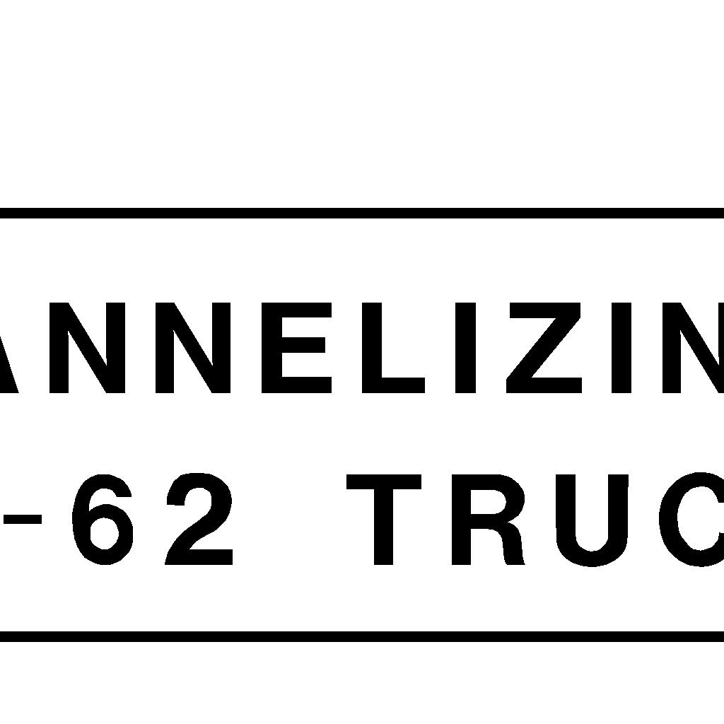
15 400 Intersection Design Right Turn Movement: Travel speed is a function of the curb radius and splitter islands between adjacent approaches Design Vehicle Another important factor determining a roundabout s layout is the need to accommodate the largest vehicle likely to use the intersection with some frequency. The turning path of this design vehicle controls many of the roundabout s dimensions. Because roundabouts are intentionally designed to slow traffic, narrow curb-to-curb widths and tight turning radii are typically used. However, if the widths and turning radii are designed too tight, difficulties for large vehicles may be created. Large trucks and buses often dictate many of the roundabout s dimensions, particularly for single-lane roundabouts. Therefore, it is very important to determine the design vehicle at the start of the design and investigative process. The choice of a design vehicle will vary depending upon the approaching roadway types and the surrounding land use characteristics. A WB-62 design vehicle should be used on roundabouts at interchanges with interstates, freeways, expressways and at intersections on arterial streets and highways. Smaller design vehicles may be chosen at local street intersections. At a minimum, fire engines, transit vehicles, and single-unit delivery vehicles should be considered in urban areas. In rural environments, school buses or farming equipment may govern design vehicle needs. Design vehicles shall traverse the roundabout without off-tracking over the outside curbing or onto the splitter island curbing. All vertical and sloped curbing shall be placed to avoid trailer off-tracking (rear axles passing over curbing). The central island curbing, the curbing outside of the roundabout and the splitter island curbing should be vertical unless mountable slope curbing is needed for specific reason Inscribed Diameter (Outside Limits of Circulatory Roadway) An engineering study (geometric, traffic operation, right-of-way) shall be performed in all cases particularly when considering less then preferred diameter as shown below. In all cases, the design vehicle shall be capable of traversing the roundabout within the circulatory roadway and using the truck apron when needed. Preferred Inscribed Diameters Single Lane: 130 feet Two Lane: 180 feet Entry and Exit Widths The entry and exit widths should accommodate the desired design vehicle and avoid off-tracking over curbing and beyond pavement limits. Preferred Entry and Exit Widths: Single Lane: 14 to 18 feet Two Lane: 28 to 30 feet July
16 400 Intersection Design Development of Entry Width for Multilane Roundabouts For locations where additional entry capacity is required, Figures and show acceptable methods of widening the roadway prior to the roundabout Exit Width Reduction of Multilane Roundabouts For locations where additional capacity is required within the roundabout but immediately reduced on the exit leg of the roundabout, the Roundabout Taper Option on Figure shows the acceptable method of reducing lanes along the roadway of the exit leg Circulatory Roadway The required width of the circulatory roadway width is determined from the width of the entries and turning requirements of the design vehicle. In general, it should be always at least as wide as the maximum entry width (up to 120 percent of the maximum entry width) and should remain constant throughout the roundabout. Preferred Circulatory Roadway Widths: Single Lane: 14 to 20 feet Two Lane: 28 to 32 feet Truck Apron A truck apron is typically used to provide additional traversable area around the central island to accommodate large vehicles. Truck apron widths should be checked with truck turning templates allowing for 2 ft. between the tire path and inside edge of the truck apron. See FHWA s Roundabouts: An Informational Guide (NCHRP Report 672) for additional truck apron details. Truck Apron Widths: 3 to 15 feet. Truck apron reveal to circulatory roadway: 2 to Gore Striping An allowable technique to maintain speed control and accommodate the design vehicle is to provide gore striping. Gore striping involves placing a striped vane island between the entry lanes to help center the vehicles within the lane and allow a cushion for off-tracking by the design vehicle Right-Turn Bypass Lanes At locations with a high volume of right-turning traffic, a right-turn bypass lane may allow a single-lane roundabout to continue to function acceptably and avoid the need to upgrade to a multilane roundabout. For additional information, see FHWA s Roundabouts: An Informational Guide (NCHRP Report 672) Cross Slopes Circulatory Roadway: 2% away from the central island. Truck Apron: 2% towards the outside. July
17 400 Intersection Design Splitter Islands Splitter islands should be provided at all roundabout approaches. Their purpose is to provide refuge for pedestrians, assist in controlling speeds, guide traffic into the roundabout, physically separate entering and exiting traffic and deter wrong-way movements. The total length of the raised island should be 50 ft. to 100 ft. On higher speed roadways, the island length should be 150 ft. to 200 ft. The minimum island width at a crosswalk should be 6 ft. July
18 400 Intersection Design Figure Date Title 401-1E October 04 Typical Crossroad Relocation July 06 Explanation of Figure E October 04 Crossroad Profile - Stop Condition - Through Road Normal Crown 401-3E July 06 Crossroad Profile - Stop Condition - Through Road Superelevated 401-4E October 04 Crossroad Profile - Signalized Intersection 401-4aE July 06 Radius Returns for Uncurbed Mainline Curbed Approach 401-4bE July 06 Radius Returns for Curbed Mainline Uncurbed Approach 401-5aE October 04 2-Lane Highway Left Turn Lane Warrant (Low Speed) 401-5bE October 04 2-Lane Highway Left Turn Lane Warrant (High Speed) 401-5cE October 04 4-Lane Highway Left Turn Lane Warrant 401-6aE October 04 2-Lane Highway Right Turn Lane Warrant (Low Speed) 401-6bE October 04 2-Lane Highway Right Turn Lane Warrant (High Speed) 401-6cE October 04 4-Lane Highway Right Turn Lane Warrant (Low Speed) 401-6dE October 04 4-Lane Highway Right Turn Lane Warrant (High Speed) 401-7E October 04 Turning Lane Design 401-8E July 18 Offset Left Turn Lane 401-9E July 18 Basis for Computing Length of Turn Lanes E July 18 Length of Storage at Intersections, and Turn Lane Design Example E October 04 Double Left Turn Lanes, and Notes E July 18 Development of Dual Left Turn Lanes aE October 04 Channelizing Island - Single Unit Truck and Passenger Car Designs bE October 04 Channelizing Island - Single Unit and Minimum WB-50 Designs cE October 04 Channelizing Island - WB-50 Truck Designs dE October 04 Channelizing Island - Typical Islands with Permitted Left Turns aE July 18 Traffic Operational Analysis Design Software bE July 13 Traffic Operational Analysis Design Software cE July 13 Traffic Operational Analysis Design Software 402-1E July 13 Add and Drop Lanes at Intersections 402-2E July 13 Add and Drop Lanes at Multilane Roundabouts 402-3E July 13 Add and Drop Lane Notes and Details * Note: For the design criteria pertaining to Collectors and Local Roads with ADT s of 400 or less, refer to the AASHTO Publication - Guidelines for Geometric Design of Very Low-Volume Local Roads ADT 400). July
19 This page is intentionally blank
20
21 Explanation of Figure Typical Crossroad Relocation 1. Curve - This portion of the crossroad can occur by itself at T type or three-legged intersections. If possible, the radius of this curve should be commensurate with the design speed of the crossroad. Often, the length of the required profile controls the work length. The horizontal curvature is then chosen so it can be accomplished within this work length. Regardless of the length of the profile adjustment, it is desirable to provide at least a 230 foot radius for this curve. When a 230 foot radius incurs high costs, it is permissible to reduce this radius to a minimum of 150 ft. 2. Tangent and Approach Radii - The crossroad in this area should have a tangent alignment. For the condition shown, the alignment between the radius returns is tangent from one side of the road to the other. However, at some intersections with a minor through movement (for example, crossroad intersections of standard diamond ramps) it may be desirable to provide different intersection angles on each side of the through road. For approach radii, see discussion in Section Curve - The statements in (1) above also apply to this curve. With the reverse curve condition shown, the radius will often not exceed 250 ft. because flatter curves make the relocation extraordinarily long. 4. Tangent - This tangent should be approximately 150 ft. in length for 30 or 40 mph design speeds on the existing road, and approximately 250 ft. for 50 or 60 mph design speeds. These lengths are generous enough to allow reasonable superelevation transitions between the reverse curves. In general, it is usually not desirable to make this tangent any longer than required. If a longer tangent can be used, the curvature or intersection angle can be improved and these two design items are more important. 5. Curve - This curve should be much flatter than the other two curves. It should be capable of being driven at the normal design speed of the existing crossroad. July 2006
22
23
24
25
26
27
28
29
30
31
32
33
34
35
36 BASIS FOR COMPUTING 401-9E LENGTH OF TURN LANES REFERENCE SECTIONS , Type of Traffic Control Signalized Unsignalized Stopped Crossroad Unsignalized Through Road Design Speed Turn Demand Volume All Low* High A ** B or C ** B or C A A A *Low is considered 10% or less of approach traffic volume **Whichever is greater A B ** B or C CONDITION A STORAGE ONLY Length = 50' (diverging taper) + Storage Length (Figure ) CONDITION B HIGH SPEED DECELERATION ONLY Design Speed Length (including 50' Diverging Taper) CONDITION C MODERATE SPEED DECELERATION AND STORAGE Design Speed Length (including 50' Diverging Taper) Storage Length (Figure ) " " " " " For explanation, see Turn Lane Design Example July 2018
37 STORAGE LENGTH E AT INTERSECTIONS REFERENCE SECTIONS , * AVERAGE * AVERAGE REQUIRED REQUIRED NO. OF NO. OF LENGTH (FT.) LENGTH (FT.) VEHICLES/CYCLE VEHICLES/CYCLE * AVERAGE VEHICLES PER CYCLE = DHV (TURNING LANE) CYCLES/HOUR IF CYCLES ARE UNKNOWN ASSUME: UNSIGNALIZED OR 2 PHASE = 60 CYCLES/HOUR 3 PHASE = 40 CYCLES/HOUR 4 PHASE = 30 CYCLES/HOUR October 2004
 = 200 veh/hr + 680 veh/hr")
38 Example - Turn Lane Design Using Figures and Problem Calculate the length of an exclusive left turn lane. Traffic Control: Signalized Design Speed: 55 mph Cycle Length: 90 sec 200 veh/hr 680 veh/hr Determine Storage and Turn Lane Lengths 200 veh/hr Turn Lane Demand (High/Low) = 200 veh/hr veh/hr Refer to the matrix in Figure = 23% = High Demand For Signalized, 55 mph, High Demand, use Method B or C, whichever is greater. Method B For 55 mph, a 285 turn lane length is required (235 storage + 50 taper). Method C For 55 mph, calculated storage length in Figure (200 veh/hr ) * (90 sec/cyc) Average Vehicles per Cycle = 3600 sec/hr Total Length = = 365 (315 storage + 50 taper) Method C = 365 > Method B = 285 Use Method C = 5 veh/cyc 200' Method C Storage Method B Storage Left Turn Storage Check Length for Thru-Block Refer to Figure to calculate thru lane(s) queue distance. 680 veh/hr / 2 lanes = 340 veh/hr/ln Thru Queue Average Vehicles per Cycle = (340 veh/hr/ln ) * (90 sec/cyc) = 9 veh/cyc/ln 350 ft/ln 3600 sec/hr Thru Block = 350 > Method C Storage = 315 Turn Lane Blocked Use 350 storage + 50 taper = 400 Turn Lane Length January 2018
39
40
41
42
43

44

45
 must use the current version of the Highway Capacity Software (HCS) by McTrans.")
46 TRAFFIC OPERATIONAL ANALYSIS DESIGN SOFTWARE aE REFERENCE SECTION Traffic operational analysis used for design purposes (i.e. determination of number and type of lanes) must use the current version of the Highway Capacity Software (HCS) by McTrans. ODOT may allow use of other traffic analysis and modeling programs when HCS is incapable of providing analysis results or when supplemental analysis is desired. Software currently used by ODOT for traffic operations analyses includes Synchro/SimTraffic, VISSIM, SIDRA, and TransModeler. Synchro/SimTraffic may be used for assessing corridor progression. However, Synchro shall not be used for design. While other programs may be considered for unique situations, it is preferred that the above identified programs be used. Default Values and Guidance The following section provides information on required input values and default values to be used for traffic analyses and methodologies. Highway Capacity Software (HCS) Streets (Signalized Intersection) Primary Input Data Traffic Storage Length, ft Enter left/right turn lane and thru lane storage, see figure to right on how values are measured. Traffic RTOR, veh/h 0 veh/h Phasing Cycle,s s, typically Phasing Uncoordinated Intersection Toggle on Phasing Field-Measured Phase Times Toggle on Timing Yellow Change, s & Red Clearance, s Minimum Y+R is 5s. Actual/calculated values may be used. Timing Minimum Green, s a) 10s for phase that includes a thru movement, b) 7s for a phase that excludes a thru movement. Note, protected lefts must have a minimum contiguous duration of 7s. Detailed Input Data General Queue Length Percentile 95 th percentile Note: A queue storage ratio (QSR) will be calculated using the storage length input and calculated queue length. If QSR exceeds 1.0, HCS will not identify that there will be spillovers into other lanes and cause unforeseen delays because HCS does not currently account for turn lane overflow and queue spillback. If possible, any QSR above 1.0 should be alleviated prior to finalizing the analysis. If not possible, microsimulation (i.e. SimTraffic) may be required. Highway Capacity Software (HCS) All Modules PHF (peak hour factor) Use HCS7 default Note: Default values shall not be used for readily available information such as acceleration/deceleration length(s), storage length(s), lane width(s), percent heavy vehicles, free-flow speed, etc. July 2018
47 TRAFFIC OPERATIONAL ANALYSIS DESIGN SOFTWARE (SIDRA) bE REFERENCE SECTION SIDRA (Limited to roundabout analyses) The settings below are for SIDRA 5.1, newer versions may be different. Parameter User selects Capacity Model In Dialogue - Tab / Section SIDRA Standard Change Setting To Level of Service Method Roundabout LOS Method Entry/Circulating Flow Adjustment HCM Delay Formula Gap-Acceptance Capacity Environmental Factor Model Settings - Options Model Settings - Roundabouts Geometry - Roundabout Data Model Settings - Options Model Settings - Options Geometry - Roundabout Data Delay (HCM 2000) Same as Signalized Intersections Medium Unchecked (HCM Delay = No) SIDRA Standard (Akçelik M3D) Opening Day Design Year January 2018
 Analysis should use a minimum of 3 simulation runs with different number seeds.")
48 TRAFFIC OPERATIONAL ANALYSIS DESIGN SOFTWARE cE REFERENCE SECTION Microsimulation software (Simtraffic/CORSIM/VISSIM) Analysis should use a minimum of 3 simulation runs with different number seeds. Refer to the FHWA Traffic Analysis Tools Program for additional guidance on using simulation software: Synchro (SimTraffic) Below is a screen capture of the minimum parameters, for the AM Peak, that must be used when running SimTraffic. These are found by selecting Options in the menu bar, then Intervals and Volumes. July 2013
400 Intersection Design
 400 Intersection Design Table of Contents 401 Intersections At-Grade... 4-1 401.1 Intersection Locations... 4-1 401.2 Intersection Traffic Control and Operational Analysis... 4-1 401.2.1 Signals. 4-1 401.2.2
400 Intersection Design. Table of Contents. 401 Intersections At-Grade Two Way Left Turn Lanes (TWLTL)... 9
... 9") 4 Intersection Design Table of Contents 41 Intersections At-Grade... 1 41.1 Intersection Locations... 1 41.2 Intersection Traffic Control and Operational Analysis... 1 41.2.1 Signals... 1 41.2.2 Stop Control...
4 Intersection Design Table of Contents 41 Intersections At-Grade... 1 41.1 Intersection Locations... 1 41.2 Intersection Traffic Control and Operational Analysis... 1 41.2.1 Signals... 1 41.2.2 Stop Control...
THE FUTURE OF THE TxDOT ROADWAY DESIGN MANUAL
 THE FUTURE OF THE TXDOT ROADWAY DESIGN MANUAL Kenneth Mora, P.E. (Design Division) 10/10/2017 Table of contents 1 2 Reduction in FHWA design controlling criteria Innovative Intersection Guidance 3-7 8-42
ROUNDABOUTS/TRAFFIC CIRCLES
 GENERAL 1. Description This standard identifies minimum requirements that shall be met for Roundabouts and Neighborhood Traffic Circles in the design and construction of elements for Arlington County Horizontal
Roundabout Prequalification Training. March 11, 2015
 Roundabout Prequalification Training March 11, 2015 Presenters American Structurepoint, Inc. Jeromy Grenard, PE, PTOE Craig Parks, PE Why Roundabouts? Everybody else is building them? They look cool? Circles
Roundabout Design Aid PREPARED BY TRAFFIC AND SAFETY
 Roundabout Design Aid PREPARED BY TRAFFIC AND SAFETY May 2018 Engineering Manual Preamble This manual provides guidance to administrative, engineering, and technical staff. Engineering practice requires
Alberta Infrastructure HIGHWAY GEOMETRIC DESIGN GUIDE AUGUST 1999
 Alberta Infrastructure HIGHWAY GEOMETRIC DESIGN GUIDE AUGUST 1999,1'(; A ACCELERATION Data on acceleration from stop D-29 Effects of grade D-35 Intersections D-97, D-99 Lanes D-97, F-5, F-7, F-15, F-21,
Update to DOTD Roundabout Design Policy
 Update to DOTD Roundabout Design Policy Roundabout In Louisiana Louisiana has 18 roundabouts in operation and 53 proposed History EDSM s or Engineering Directives and Standards set DOTD policies, procedures,
Access Location, Spacing, Turn Lanes, and Medians
 Design Manual Chapter 5 - Roadway Design 5L - Access Management 5L-3 Access Location, Spacing, Turn Lanes, and Medians This section addresses access location, spacing, turn lane and median needs, including
Traffic Academy: IJS & IMS FAQ/RULES OF THUMB
 FAQ/RULES OF THUMB HCS intersection analysis criteria See LDM Figure 401-14aE Cycle lengths between 60 to 120 seconds No impractical phases, i.e., 1 second green time Yellow + All Red must be no less than
Modern Roundabouts: a guide for application
 Modern Roundabouts: a guide for application Kentucky Community Transportation Innovation Academy 2005 The contents of this booklet reflect the views of the authors who are responsible for the facts and
Design of Turn Lane Guidelines
 Design of Turn Lane Guidelines CTS Transportation Research Conference May 24, 2012 Howard Preston, PE Minnesota Department of Transportation Research Services Office of Policy Analysis, Research & Innovation
133 rd Street and 132 nd /Hemlock Street 132 nd Street and Foster Street MINI ROUNDABOUTS. Overland Park, Kansas
 133 rd Street and 132 nd /Hemlock Street 132 nd Street and Foster Street MINI ROUNDABOUTS Overland Park, Kansas September 1, 2017 TABLE OF CONTENTS 1. INTRODUCTION... 1 2. LITERATURE REVIEW... 1 3. CONCEPT
TECHNICAL MEMORANDUM VDOT Central Region On Call Task Order
 Kittelson & Associates, Inc. T R A N S P O R T A T I O N E N G I N E E R I N G / P L A N N I N G 1850 Centennial Park Drive, Suite 130, 20191 P 703-885-8970 F 703-885-8971 TECHNICAL MEMORANDUM VDOT Central
Figure 3B-1. Examples of Two-Lane, Two-Way Marking Applications
 Figure 3B-1. Examples of Two-Lane, Two-Way Marking Applications A - Typical two-lane, two-way marking with passing permitted in both directions B - Typical two-lane, two-way marking with no-passing zones
Access Management in the Vicinity of Intersections
 Access Management in the Vicinity of Intersections FHWA-SA-10-002 Technical Summary Photo: Ralph Bentley (used with permission) 0 Access Management is: The design, implementation and management of entry
3-13 UFC - GENERAL PROVISIONS AND GEOMETRIC DESIGN FOR ROADS, STREETS, WALKS, AND OPEN
 maintenance, and erosion. Stability is required to maintain the integrity of the pavement structure, and a slope stability analysis should be conducted for cuts and fills greater than 15 feet. For lower
CHAPTER 1 STANDARD PRACTICES
 CHAPTER 1 STANDARD PRACTICES OBJECTIVES 1) Functions and Limitations 2) Standardization of Application 3) Materials 4) Colors 5) Widths and Patterns of Longitudinal Pavement Marking Lines 6) General Principles
General References Definitions. (1) Design Guidance. (2) Supporting Information
 Design Guidance. (2) Supporting Information") Chapter 1240 Turning Roadways 1240.01 General 1240.02 References 1240.03 Definitions 1240.04 Turning Roadway Widths 1240.05 Documentation 1240.01 General The roadway on a curve may need to be widened to
Chapter 1240 Turning Roadways 1240.01 General 1240.02 References 1240.03 Definitions 1240.04 Turning Roadway Widths 1240.05 Documentation 1240.01 General The roadway on a curve may need to be widened to
Course Instructions. 3 Easy Steps to Complete the Course: 1.) Read the Course PDF Below.
 Read the Course PDF Below.") Course Instructions NOTE: The following pages contain a preview of the final exam. This final exam is identical to the final exam that you will take online after you purchase the course. After you purchase
Course Instructions NOTE: The following pages contain a preview of the final exam. This final exam is identical to the final exam that you will take online after you purchase the course. After you purchase
Traffic Engineering and Highway Safety Bulletin June Overview
 Traffic Engineering and Highway Safety Bulletin 18-03 June 2018 INTERSECTION GEOMETRIC DESIGN In This Issue Overview... 1 Intersection Types... 2 Traffic Control Selection... 3 Capacity Analysis... 6 Design
Recommended Roadway Plan Section 2 - Land Development and Roadway Access
 Recommended Roadway Plan Section 2 - Land Development and Roadway Access SECTION 2 Land Development and Roadway Access 2.1 Land Use and Access Management The Federal Highway Administration (FHWA) defines
Driveway Design Criteria
 Design Manual Chapter 5 - Roadway Design 5L - Access Management 5L-4 Driveway Design Criteria A. General For efficient and safe operations, access drives and minor public street intersections can be improved
INDEX. Geometric Design Guide for Canadian Roads INDEX
 Acceleration lane, see Lanes, Acceleration Access, 8.1 Access Management and Functional Classification 8.2 Access Management by Design Classification 8.3 Access Configuration 8.4 Building Set-Back Guidelines
1.3.4 CHARACTERISTICS OF CLASSIFICATIONS
 Geometric Design Guide for Canadian Roads 1.3.4 CHARACTERISTICS OF CLASSIFICATIONS The principal characteristics of each of the six groups of road classifications are described by the following figure
October 2004 REVISIONS (2) SUPERELEVATION DEVELOPMENT 11.3(2)
 SUPERELEVATION DEVELOPMENT 11.3(2)") October 2004 REVISIONS (2) Chapter 11 HORIZONTAL ALIGNMENT SUPERELEVATION DEVELOPMENT 11.3(2) Chapter 12 VERTICAL ALIGNMENT VERTICAL CURVES PASSING SIGHT DISTANCE 12.5(2) VERTICAL CURVES STOPPING SIGHT
October 2004 REVISIONS (2) Chapter 11 HORIZONTAL ALIGNMENT SUPERELEVATION DEVELOPMENT 11.3(2) Chapter 12 VERTICAL ALIGNMENT VERTICAL CURVES PASSING SIGHT DISTANCE 12.5(2) VERTICAL CURVES STOPPING SIGHT
Figure 1: Graphical definitions of superelevation in terms for a two lane roadway.
 Iowa Department of Transportation Office of Design Superelevation 2A-2 Design Manual Chapter 2 Alignments Originally Issued: 12-31-97 Revised: 12-10-10 Superelevation is the banking of the roadway along
WYDOT DESIGN GUIDES. Guide for. Non-NHS State Highways
 WYDOT DESIGN GUIDES Guide for Non-NHS State Highways 2014 GUIDE FOR Non-NATIONAL HIGHWAY SYSTEM (Non-NHS) STATE HIGHWAYS PRESERVATION REHABILITATION RECONSTRUCTION INTRODUCTION This Guide is directed to
Chapter Twenty-eight SIGHT DISTANCE BUREAU OF LOCAL ROADS AND STREETS MANUAL
 Chapter Twenty-eight SIGHT DISTANCE BUREAU OF LOCAL ROADS AND STREETS MANUAL Jan 2006 SIGHT DISTANCE 28(i) Chapter Twenty-eight SIGHT DISTANCE Table of Contents Section Page 28-1 STOPPING SIGHT DISTANCE
Roadway Design Manual
 Roadway Design Manual Manual Notice Archive by Texas Department of Transportation (512) 302-2453 all rights reserved Manual Notice 2009-1 From: Manual: Mark A. Marek, P.E Roadway Design Manual Effective
WYDOT DESIGN GUIDES. Guide for. NHS Arterial (Non-Interstate)
") WYDOT DESIGN GUIDES Guide for NHS Arterial (Non-Interstate) 2014 GUIDE FOR NATIONAL HIGHWAY SYSTEM (NHS) HIGHWAYS (NHS ARTERIALS, Non-Interstate) PRESERVATION REHABILITATION RECONSTRUCTION INTRODUCTION
WYDOT DESIGN GUIDES Guide for NHS Arterial (Non-Interstate) 2014 GUIDE FOR NATIONAL HIGHWAY SYSTEM (NHS) HIGHWAYS (NHS ARTERIALS, Non-Interstate) PRESERVATION REHABILITATION RECONSTRUCTION INTRODUCTION
INTERSECTIONS AT GRADE INTERSECTIONS
 INTERSECTIONS 1 AT GRADE INTERSECTIONS INTERSECTIONS INTERSECTIONS = INTERRUPTED FACILITIES Definitions and key elements An intersection is defined as an area where two or more roadways join or cross.
CHAPTER 3A. GENERAL PAGE CHAPTER 3B. PAVEMENT AND CURB MARKINGS PAGE
 Virginia Supplement to the 2009 MUTCD Revision 1 Page TC-3-1 PART 3. MARKINGS CHAPTER 3A. GENERAL PAGE Section 3A.01 Functions and Limitations Section 3A.02 Standardization of Application Section 3A.03
CHAPTER 6H. TYPICAL APPLICATIONS
 Section 6H.01 Typical Applications Support: CHAPTER 6H. TYPICAL APPLICATIONS Chapter 6G contains discussions of typical temporary traffic control activities. Chapter 6H presents typical applications for
Design of Suburban Highways
 Design of Suburban Highways by David L. Heavey, P.E. TABLE OF CONTENTS Introduction...3 Design Speed, Posted Speed and Operating Speed...4 Median Types...5 Raised Medians...9 Common Suburban Roadway Typical
Truck Climbing Lane Traffic Justification Report
 ROUTE 7 (HARRY BYRD HIGHWAY) WESTBOUND FROM WEST MARKET STREET TO ROUTE 9 (CHARLES TOWN PIKE) Truck Climbing Lane Traffic Justification Report Project No. 6007-053-133, P 101 Ι UPC No. 58599 Prepared by:
Geometric Design Tables
 Design Manual Chapter 5 - Roadway Design 5C - Geometric Design Criteria 5C-1 Geometric Design Tables A. General The following sections present two sets of design criteria tables - Preferred Roadway Elements
Roadway Intersection Design Gregory J. Taylor, P.E.
 Roadway Intersection Design by Gregory J. Taylor, P.E. INTRODUCTION This course summarizes and highlights the geometric design process for modern roadway intersections. This document is intended to explain
Roundabout Design 101: Roundabout Capacity Issues
 Design 101: Capacity Issues Part 2 March 7, 2012 Presentation Outline Part 2 Geometry and Capacity Choosing a Capacity Analysis Method Modeling differences Capacity Delay Limitations Variation / Uncertainty
MUTCD Part 6G: Type of Temporary Traffic Control Zone Activities
 MUTCD Part 6G: Type of Temporary Traffic Control Zone Activities 6G.01 Typical Applications Each temporary traffic control (TTC) zone is different. Many variables, such as location of work, highway type,
TRAFFIC LINE MANUAL. June 2011 TRAFFIC-ROADWAY SECTION
 TRAFFIC LINE MANUAL TRAFFIC-ROADWAY SECTION TABLE OF CONTENTS Foreword...iv Section A: General Principles A-1 Functions and Limitations... 1 A-2 Colors... 1 A-3 Colored Pavements... 1 A-4 Functions, Widths,
BDC07MR-05. Section 6
 BDC07MR-05 Section 6 6.1 General Most highways intersect at grade. To minimize the resulting conflicts and to provide adequately for the anticipated crossings and turning movements, the geometric design
TRAFFIC LINE MANUAL Edition Revision 1 June 2012 TRAFFIC-ROADWAY SECTION
 TRAFFIC LINE MANUAL 2011 Edition Revision 1 June 2012 TRAFFIC-ROADWAY SECTION TABLE OF CONTENTS Foreword...iv Section A: General Principles A-1 Functions and Limitations... 1 A-2 Colors... 1 A-3 Colored
Designing for Pedestrian Safety. Alabama Department of Transportation Pre-Construction Conference May 2016
 Designing for Pedestrian Safety Alabama Department of Transportation Pre-Construction Conference May 2016 1 Designing for Pedestrians Marking Crosswalks at Signalized intersections High Visibility Markings
SECTION 1A NEW JERSEY TURNPIKE GEOMETRIC DESIGN
 SECTION 1A NEW JERSEY TURNPIKE GEOMETRIC DESIGN Table of Contents Page No 1A.1 GENERAL...1 1A.1.1 DESIGN CONTROLS...1 1A.2 MAINLINE ROADWAYS...4 1A.2.1 ROADWAY DESIGNATION...4 1A.2.2 DESIGN SPEED...4 1A.2.3
DEFINITIONS Activity Area - Advance Warning Area Advance Warning Sign Spacing Advisory Speed Approach Sight Distance Attended Work Space
 DEFINITIONS Activity Area - that part of a TTC zone activity area where the work actually takes place. It consists of the work space, traffic space and one or more buffer spaces. Advance Warning Area -
JUNE, 2000 ROAD DESIGN MANUAL 5-0(1) CHAPTER 5 AT-GRADE INTERSECTIONS
 CHAPTER 5 AT-GRADE INTERSECTIONS") JUNE, 2000 ROAD DESIGN MANUAL 5-0(1) CHAPTER 5 AT-GRADE INTERSECTIONS 5-1.0 INTRODUCTION 5-1.01 Definition 5-1.02 Policy 5-1.03 Design Considerations 5-1.04 Vehicle Characteristics 5-1.04.01 Turning Radii
JUNE, 2000 ROAD DESIGN MANUAL 5-0(1) CHAPTER 5 AT-GRADE INTERSECTIONS 5-1.0 INTRODUCTION 5-1.01 Definition 5-1.02 Policy 5-1.03 Design Considerations 5-1.04 Vehicle Characteristics 5-1.04.01 Turning Radii
Active Transportation Facility Glossary
 Active Transportation Facility Glossary This document defines different active transportation facilities and suggests appropriate corridor types. Click on a facility type to jump to its definition. Bike
Design of Roundabouts A SunCam online continuing education course
 Design of Roundabouts by Debra A. Kennaugh, P.E. www.suncam.com Copyright 2010 Debra A. Kennaugh Page 1 of 48 I. Introduction A. Types of Circular Intersections B. Roundabout Features C. Roundabout Dimensions
Defining Purpose and Need
 Advanced Design Flexibility Pilot Workshop Session 4 Jack Broz, PE, HR Green May 5-6, 2010 Defining Purpose and Need In your agency s project development process, when do design engineers typically get
Section 3A.04 Colors. Section 3B.10 Approach Markings for Obstructions
 Section 3A.04 Colors Markings shall be yellow, white, red, or blue, or purple. The colors for markings shall conform to the standard highway colors. Black in conjunction with one of the above colors shall
Roundabouts 101: As Easy as 1-2-3
 Roundabouts 101: As Easy as 1-2-3 APWA Monterey Bay Training Conference June 28, 2016 Watsonville, CA Brian L. Ray Kittelson & Associates, Inc. Presentation Outline Overview Roundabout Size Roundabout
City of Wayzata Comprehensive Plan 2030 Transportation Chapter: Appendix A
 A1. Functional Classification Table A-1 illustrates the Metropolitan Council s detailed criteria established for the functional classification of roadways within the Twin Cities Metropolitan Area. Table
CHAPTER 6H. TYPICAL APPLICATIONS
 2006 Edition Page 6H-1 CHAPTER 6H. TYPICAL APPLICATIONS Section 6H.01 Typical Applications Support: Whenever the acronym TTC is used in this Chapter, it refers to temporary traffic control. Standard: The
Off-road Trails. Guidance
 Off-road Trails Off-road trails are shared use paths located on an independent alignment that provide two-way travel for people walking, bicycling, and other non-motorized users. Trails specifically along
10.0 CURB EXTENSIONS GUIDELINE
 10.0 CURB EXTENSIONS GUIDELINE Road Engineering Design Guidelines Version 1.0 March 2017 City of Toronto, Transportation Services City of Toronto Page 0 Background In early 2014, Transportation Services
Practical Application of Turn Lane Design Criteria in Developing Suburban & Urban Corridors
 Practical Application of Turn Lane Design Criteria in Developing Suburban & Urban Corridors Presented by Gilmer D. Gaston, P.E., PTOE October 14, 2014 San Antonio Austin Houston Fort Worth Dallas When
TRANSPORTATION ANALYSIS REPORT US Route 6 Huron, Erie County, Ohio
 TRANSPORTATION ANALYSIS REPORT US Route 6 Huron, Erie County, Ohio December 12, 2012 Prepared for: The City of Huron 417 Main Huron, OH 44839 Providing Practical Experience Technical Excellence and Client
Developed by: The American Traffic Safety Services Association (ATSSA) 15 Riverside Parkway, Suite 100 Fredericksburg, VA
 15 Riverside Parkway, Suite 100 Fredericksburg, VA") Addendum Developed by: The American Traffic Safety Services Association (ATSSA) 15 Riverside Parkway, Suite 100 Fredericksburg, VA 22406-1022 800-272-8772 This material is based upon work supported by
Addendum Developed by: The American Traffic Safety Services Association (ATSSA) 15 Riverside Parkway, Suite 100 Fredericksburg, VA 22406-1022 800-272-8772 This material is based upon work supported by
Technical Memorandum. Subject: Interchange Ramp Terminal Configuration. Expiration. Implementation. Introduction
 Minnesota Department of Transportation Engineering Services Division Technical Memorandum To: Electronic Distribution Recipients From: Nancy T. Daubenberger, P.E. Assistant Commisioner, Engineering Services
Roundabouts. By: Nezamuddin, Valparaiso University. February 19, 2015
 Roundabouts By: Nezamuddin, Valparaiso University February 19, 2015 Outline 1. Background on Roundabouts 2. Silhavy Rd. Corridor Improvement Project in Valparaiso, IN 3. 5-points Roundabout in Valparaiso,
SECTION 12 ROAD MARKINGS AND DELINEATION
 SECTION 12 ROAD MARKINGS AND DELINEATION (Blank Page) MANUAL OF TRAFFIC SIGNS AND MARKINGS - Part III: Motorways and Expressways 12-1 12.1 GENERAL 12.1.1 INTRODUCTION The markings and delineation details
Figure 1: Vicinity Map of the Study Area
 ARIZONA TEXAS NEW MEXICO OKLAHOMA May 5, 2016 Mr. Anthony Beach, P.E. BSP Engineers 4800 Lakewood Drive, Suite 4 Waco, Texas 76710 Re: Intersection and Access Analysis along Business 190 in Copperas Cove
Technical Summary Roundabouts
 Technical Summary Roundabouts FHWA-SA-10-006 Foreword This technical summary is designed as a reference for State and local transportation officials, Federal Highway Administration (FHWA) Division Safety
Kane County Division of Transportation. Roundabout Selection and Design Guide
 Kane County Division of Transportation Roundabout Selection and Design Guide January 22, 2007 Prepared by: TranSystems 1051 Perimeter Drive, Suite 1025 Schaumburg, IL 60173-5058 Table of Contents Table
American Fork City Access Management Manual
 American Fork City Access Management Manual American Fork, Utah April 2012 UT09-181 3315 West Mayflower Way, Ste. 4 Lehi, Utah 84043 p. 801/ 766.4343 www.halesengineering.com EXECUTIVE SUMMARY As traffic
CITY OF SARATOGA SPRINGS PEDESTRIAN CROSSING TOOLBOX
 CITY OF SARATOGA SPRINGS PEDESTRIAN CROSSING TOOLBOX This toolbox is to be used to guide pedestrian crossing improvements within the City of Saratoga Springs. Details for each crossing type are provided.
Roundabout Design 101: Principles, Process, and Documentation
 Design 101: Principles, Process, and Documentation Part 1 March 7, 2012 Well designed roundabouts should minimize accidents, delay and costs for everyone using the intersection. This session covers the
JCE 4600 Transportation Engineering. Traffic Control
 JCE 4600 Transportation Engineering Traffic Control Human Factors Primary Driving Tasks NAVIGATION GUIDANCE CONTROL What makes a Traffic Control Device Effective? Fulfill a need Command Attention Convey
4.1 CONTEXT. The existing terrain and sight conditions will affect available sight lines and approach speeds of bicyclists and motorists.
 4 INTERSECTION DESIGN This chapter provides key principles that should be used to develop and evaluate design approaches and treatments that will result in intersections that support all ages and abilities
KDOT Access Management Policy (AMP)
") KDOT Access Management Policy (AMP) (January 2013 Edition) Errata KDOT intends to correct these errors during the next revision to the Policy. Corrections are denoted in red text with a solid line through
KDOT Access Management Policy (AMP) (January 2013 Edition) Errata KDOT intends to correct these errors during the next revision to the Policy. Corrections are denoted in red text with a solid line through
9.1 FUNCTIONAL HIGHWAY SYSTEMS IN URBANIZED AREAS Principal Arterial Interstate Principal Arterial Non-Interstate
 Greater Bozeman Area Transportation Plan (2007 Update) Chapter 9: Recommended Major Street Network & Roadway Typical Sections 9.1 FUNCTIONAL HIGHWAY SYSTEMS IN URBANIZED AREAS The discussion in this Chapter
DESIGN BULLETIN #66/2010
 DESIGN BULLETIN #66/2010 Highway Geometric Design Guide Chapter B, Climbing Lane Warrants for Two Lane Undivided and Four Lane Divided Highways - Revised Summary This Design Bulletin is being issued as
Best Practices for the Design and Operation of Reduced Conflict Intersections
 Best Practices for the Design and Operation of Reduced Conflict Intersections OCTOBER 2016 Prepared By: Table of Contents INTRODUCTION... 5 Purpose... 5 Definition... 5 Advantages... 6 Disadvantages...
Facilities Development Manual
 State of Wisconsin Department of Transportation Facilities Development Manual ORIGINATOR Director, Bureau of Highway Development PROCEDURE 11-26-5 CHAPTER 11 Design SECTION 26 Roundabouts SUBJECT 5 Scoping
GDOT Elements of Design. Course ID: GDOT PDH Credits
 GDOT Elements of Design Course ID: GDOT-06 3 PDH Credits Civil Engineer Educators LLC 1026 Timberwolf Lane Juneau, AK 99801 Email: support@civilpdh.com Chapter 4 Contents 4. ELEMENTS OF DESIGN 1 4.1. Sight
Chapter 4 Traffic Analysis
 Chapter 4 Traffic Analysis PURPOSE The traffic analysis component of the K-68 Corridor Management Plan incorporates information on the existing transportation network, such as traffic volumes and intersection
Acknowledgements. Mr. David Nicol 3/23/2012. Daniel Camacho, P.E. Highway Engineer Federal Highway Administration Puerto Rico Division
 Daniel Camacho, P.E. Highway Engineer Federal Highway Administration Puerto Rico Division Acknowledgements Mr. David Nicol Director, FHWA Office of Safety FHWA Office of Safety http://safety.fhwa.dot.gov/provencountermeasures/
ORANGE COUNTY PUBLIC WORKS TRAFFIC INVESTIGATIONS
 ORANGE COUNTY PUBLIC WORKS TRAFFIC INVESTIGATIONS STAFF REPORT OF: January 6, 2019 SUPERVISORIAL DISTRICT: 5 SUBJECT: LOCATION: INVESTIGATOR: O Neill Drive at Roanoke Drive; Ladera Ranch; TB 922-E6 Clever
Traffic Signal Design
 Traffic Signal Design Instructor: S. M. Mahdi Amiripour m.amiripour@gmail.com 2 Introduction Intersection is an area shared by two or more roads Designated for the vehicles to turn to different directions
Town of Mooresville, North Carolina Neighborhood Traffic Calming and Control Device Policy
 Town of Mooresville, North Carolina Neighborhood Traffic Calming and Control Device Policy Adopted January 6, 2014 Town of Mooresville Development Services Department TOWN OF MOORESVILLE NEIGHBORHOOD TRAFFIC
TRAFFIC AND SAFETY NOTE 608A. Spacing for Commercial Drives and Streets. To Promote a Uniform Practice in Determining Access Spacing
 TRAFFIC AND SAFETY NOTE 608A SUBJECT: PURPOSE: Spacing for Commercial Drives and Streets To Promote a Uniform Practice in Determining Access Spacing COORDINATING UNIT: Geometric Design Unit INFORMATION:
Appendix T CCMP TRAIL TRAFFIC & TRANSPORTATION DESIGN STANDARD
 Appendix T CCMP 3.3.4 TRAIL TRAFFIC & TRANSPORTATION DESIGN STANDARD 3.3.4 Trail Traffic and Transportation Design Multi-use trails have certain design standards, which vary depending on the agency that
This document was prepared by DLZ Michigan, Inc. under the direction of MDOT s Roundabout Committee which consists of the following individuals:
 FOREWORD With the study, design, and construction of modern roundabouts (referred to in this document as roundabouts ) becoming commonplace throughout the state of Michigan, the Michigan Department of
Intersection Geometric Design
 Course No: C04-033 Credit: 4 PDH Gregory J. Taylor, P.E. Continuing Education and Development, Inc. 9 Greyridge Farm Court Stony Point, NY 10980 P: (877) 322-5800 F: (877) 322-4774 info@cedengineering.com
2014 FHWA Aging Road User Handbook. Recommendations to Accommodate Aging Pedestrians. Lifesaver National Conference. What is the Handbook?
 2014 FHWA Aging Road User Handbook Recommendations to Accommodate Aging Pedestrians Lifesaver National Conference March 17, 2015 Revised June 2014 1 What is the Handbook? 1998 1st Edition 2001 2nd Edition
Focus of activity - The land near intersections often contains a concentration of travel destinations.
 Chapter 6 Intersection Design 6.1 Introduction An intersection is the area where two or more streets join or cross at-grade. The intersection includes the areas needed for all modes of travel: pedestrian,
PEDESTRIAN ACCOMMODATIONS DPS 201 AT INTERCHANGES
 PEDESTRIAN ACCOMMODATIONS DPS 201 AT INTERCHANGES UNDERSTANDING THE ISSUES Intersections of freeway ramp terminals at crossroads are the most critical components of an interchange Challenge: balance mobility
DISTRIBUTION: Electronic Recipients List TRANSMITTAL LETTER NO. (17-01) MINNESOTA DEPARTMENT OF TRANSPORTATION. MANUAL: Road Design English Manual
 MINNESOTA DEPARTMENT OF TRANSPORTATION. MANUAL: Road Design English Manual") DISTRIBUTION: Electronic Recipients List MINNESOTA DEPARTMENT OF TRANSPORTATION DEVELOPED BY: Design Standards Unit ISSUED BY: Office of Project Management and Technical Support TRANSMITTAL LETTER NO.
DISTRIBUTION: Electronic Recipients List MINNESOTA DEPARTMENT OF TRANSPORTATION DEVELOPED BY: Design Standards Unit ISSUED BY: Office of Project Management and Technical Support TRANSMITTAL LETTER NO.
City of Vallejo Traffic Calming Toolbox
 City of Vallejo Traffic Calming Toolbox June 1, 2013 Final Table of Contents Introduction... 1 Non-Physical Devices... 3 High-Visibility Crosswalk... 3 In Pavement Lighted Crosswalk... 4 Rapid Flashing
Chapter 2: Standards for Access, Non-Motorized, and Transit
 Standards for Access, Non-Motorized, and Transit Chapter 2: Standards for Access, Non-Motorized, and Transit The Washtenaw County Access Management Plan was developed based on the analysis of existing
Section 4 Basic Geometric Design Elements
 4.1 General Section 4 Basic Geometric Design Elements BDC07MR-01 Geometric highway design pertains to the visible features of the highway. It may be considered as the tailoring of the highway to the terrain,
Traffic Impact Analysis Chatham County Grocery Chatham County, NC
 Chatham County Grocery Chatham County, NC TABLE OF CONTENTS 1. INTRODUCTION... 1 1.1. Location and Study Area... 1 1.2. Proposed Land Use and Access... 2 1.3. Adjacent Land Uses... 2 1.4. Existing ways...
Chapter 7 Intersection Design
 hapter 7 Dr. Yahya Sarraj Faculty of Engineering The Islamic University of Gaza An intersection is an area, shared by two or more roads, whose main function is to provide for the change of route directions.
Document 2 - City of Ottawa Pedestrian Crossover (PXO) Program
 Program") 40 Document 2 - City of Ottawa Pedestrian Crossover (PXO) Program OVERVIEW The City of Ottawa Pedestrian Crossover (PXO) Program provides the basis for PXO implementation in Ottawa. The program s processes
40 Document 2 - City of Ottawa Pedestrian Crossover (PXO) Program OVERVIEW The City of Ottawa Pedestrian Crossover (PXO) Program provides the basis for PXO implementation in Ottawa. The program s processes
INDUSTRIAL BUILDING 3009 HAWTHORNE ROAD CITY OF OTTAWA TRANSPORTATION OVERVIEW REVISED. Prepared for: Canada Inc.
 INDUSTRIAL BUILDING 3009 HAWTHORNE ROAD CITY OF OTTAWA TRANSPORTATION OVERVIEW REVISED Prepared for: 7849648 Canada Inc. Octiober 1, 2015 114-598 Overview_2.doc D. J. Halpenny & Associates Ltd. Consulting
M-58 HIGHWAY ACCESS MANAGEMENT STUDY Mullen Road to Bel-Ray Boulevard. Prepared for CITY OF BELTON. May 2016
 M-58 HIGHWAY ACCESS MANAGEMENT STUDY Prepared for CITY OF BELTON By May 2016 Introduction Missouri State Highway 58 (M-58 Highway) is a major commercial corridor in the City of Belton. As development has
Subject: Use of Pull-off Areas in Work Zones Page: 1 of 13. Brief Description: Guidance for the use and placement of pull-off area in work zones.
 6 - G2 Subject: Use of Pull-off Areas in Work Zones Page: 1 of 13 MdMUTCD REF. NO. None Date Issued: 09/09 Effective Date: 09/09 Brief Description: Guidance for the use and placement of pull-off area in
METHODOLOGY. Signalized Intersection Average Control Delay (sec/veh)
") Chapter 5 Traffic Analysis 5.1 SUMMARY US /West 6 th Street assumes a unique role in the Lawrence Douglas County transportation system. This principal arterial street currently conveys commuter traffic
Chapter 5 Traffic Analysis 5.1 SUMMARY US /West 6 th Street assumes a unique role in the Lawrence Douglas County transportation system. This principal arterial street currently conveys commuter traffic
200 Horizontal and Vertical Design. Table of Contents
 200 Horizontal and Vertical Design Table of Contents 201 Sight Distance... 2-1 201.1 General... 2-1 201.2 Stopping Sight Distance... 2-1 201.2.1 Horizontal Sight Distance... 2-2 201.2.2 Vertical Stopping