HermanMiller Aeron. New Aeron Disassembly for Recycling. Materials Identification and Segregation: Tools Required. Step 1
|
|
|
- Herbert Wiggins
- 5 years ago
- Views:
Transcription

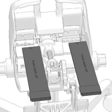
1 HermanMiller Aeron For more information about our products and services or to see a list of dealers, please visit us at or call Herman Miller, Inc., Zeeland, Michigan Printed in U.S.A. Part No. 1BHGYK - A. New Aeron Disassembly for Recycling Materials Identification and Segregation: Where possible, plastic components are marked with ASTM recycling codes. Use these codes to identify material type for recycling. Non marked components should be treated as mixed plastic. Ferrous metals can be identified using a small magnet for recycling. Non-ferrous metals should be separated and recycled separately. Tools Required Safety Glasses Electric Drill Hammer Punch T27 Torx driver Nylon cap Wrench 10 mm Flat screw driver Special punch with recess T40, T25 Torx bit 5mm, 6mm Hex bit Step Remove the four back bolts using 5mm Hex bit


2 Step Detach the Back from the chair 2.1 Remove the bolt from the right swing arm. 2.2 Right hand arm has right hand drive threads. 2.3 Follow the previous steps to remove the left arm. Left hand arm has reverse left hand drive threads. 2


3 Step Remove nut and shoulder bolt 3.2 Use T27 Torx driver and 10 mm wrench Follow previous steps to remove the right side nut and shoulder bolt 3


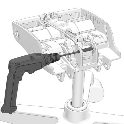
4 3.5 Use 6 mm drill bit to remove the bolt from the swing arm Follow the previous step to remove the bolt on the other side


5 Step Detach the seat from the swing arm 4.1 Remove the lower cover by releasing the 4 snaps 4.2 Squeeze the snaps as indicated below to remove the cover 4.3 Detach the lower cover from the tilt assembly. 5


6 4.4 Detach the back cover Remove the front cover


7 Step Detaching director from the tilt housing. 5.2 Release the two snaps shown below Lift the director from the tilt housing. 7


8 5.5 Release the snap shown below to lift the cable. 5.6 Lift the cable to remove from the actuator. 5.7 Slide out the cable to detach from the actuator. 5.8 Removing the handle from the swing arm. 8


9 5.9 Lift the lever up Release the bottom snap shown in the Release the bracket out of the socket. 9


10 5.13 Rotate the assembly and remove from the swing arm Step Detach the swing arms. 6.2 Pull out the swing arms from the assembly. 10


11 6.3 Rotate the knob counter clock wise to release tension 6.4 Insert the screw driver to release the knob. 6.5 Detach the knob from the assembly. 6.6 Insert the screw driver to release the knob 11


12 6.7 Detach the knob from the assembly. 6.8 Use the swing arm and pull back and hold to release the forward limit. 6.9 While holding back swing arm, lift the tab to disengage the forward limit


13 6.11 Rotate the casing to remove the leaf spring from the assembly Detach the Leaf spring from the assembly


14 6.15 Use T40 torx bit to remove the pivot pin Remove the other pivot pin joint using the previous step


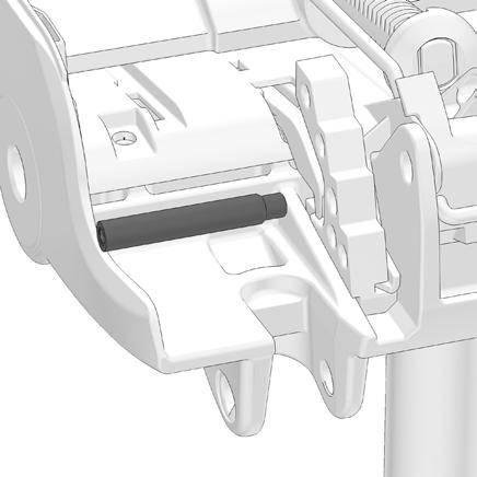
15 6.19 Remove the bushing Detach the tilt casting from assembly Use hammer and punch to tap out the bushing to remove the B-Link


16 6.23 Follow the previous step to remove the right hand side bushing Detach the B-Link from the assembly Use T25 Torx bit to remove the cassette bolts 16

17


18 After removing all the cassette bolts detach the tilt cassette Use a punch with recess and hammer to remove the tilt housing. Attention: Hold the tilt casting and lift the whole unit in the air before hammering. 18


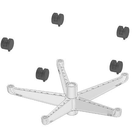
19 Step Use nylon cap and Hammer to remove the cylinder form the base Pull off the castors to disassemble from the base 19
20 7.4 20
SERIES 2 RAMP OWNER S MANUAL TOOLS REQUIRED: BEFORE YOU BEGIN... Read and understand these instructions before beginning a ramp setup.
 SERIES 2 RAMP OWNER S MANUAL BEFORE YOU BEGIN... Read and understand these instructions before beginning a ramp setup. Use caution and care for your back when lifting, pushing, pulling, folding or unfolding
VERSA BIKE RACK INSTRUCTIONS
 VERSA BIKE RACK INSTRUCTIONS Models #8, 8 Important This rack is designed for use with a or. receiver hitch. The rack is designed to hold a maximum of two bicycles. Do not use it for anything other than
Fontaine Fifth Wheel Ultra LT Rebuild Procedures
 Fontaine Fifth Wheel Ultra LT Rebuild Procedures Disassembly Assembly Adjustments 800-874-9780 2010 LT-147 January 2010 Dissassembly Cover plate removed for clarity. Refer to exploded view of assembly
Magnetic Bike. Model No: AENERGISER BODY WORX. Retain this owner s manual for future reference Read and follow all instructions in this owner s manual
 BODY WORX Magnetic Bike Model No: AENERGISER Retain this owner s manual for future reference Read and follow all instructions in this owner s manual Version A 1 EXPLODE DRAWING -02- PARTS LIST AND TOOLS
CHAPTER 5 REWIND STARTERS
 GENERAL INFORMATION CHAPTER 5 REWIND S Rewind starters used on vertical shaft Tecumseh engines are top mount horizontal pull style or side mount vertical pull style. Horizontal shaft engines use side mounted
FIRST TEAM SPORTS, INC Storm Portable Series Assembly Instructions
 FIRST TEAM SPORTS, INC Storm Portable Series Assembly Instructions WARNING! WARNING! WARNING! THIS BASKETBALL SYSTEM IS SPRING LOADED AND SHIPPED UNDER TENSION. ATTEMPTING TO ASSEMBLE OR DISASSEMBLE ANY
SECTION 2 RING MOUNT
 SECTION 2 RING MOUNT Rotax aircraft engines are manufactured and supported by Rotax GmbH of Austria. Read and understand the Rotax manuals completely before starting with the engine installation, as they
600 / 600FC OWNER'S MANUAL
 PROGRESSION 600 / 600FC OWNER'S MANUAL Issue 2 / Version E - Dec. 10, 1997 Copyright 1997 GAMMA Sports - All Rights Reserved PROGRESSION 600 / 600FC OWNER'S MANUAL TABLE OF CONTENTS PAGE 1... WARRANTY
Assembly Instructions
 CS-B-FM Assembly Instructions Thank you for purchasing a Shelti product. All of us at Shelti want you to be completely satisfied with your Pro Foos game, so feel free to contact us for help with the assembly
3 in 1 Robot Gripper Assembly Guide
 3 in 1 Robot Gripper Assembly Guide 1/ Content Part List 3 Assemble Guide of Two Finger Gripper 4 Assemble Guide of Four Cross Finger Gripper 12 Assemble Guide of Parallel Four Finger Gripper 15 2/ Part
Final Assembly Instructions Bikes with Threaded Headsets
 Final Assembly Instructions Bikes with Threaded Headsets Thank you for buying your new bicycle from L.L.Bean. Read these instructions carefully before beginning the final assembly. Prior to shipping, our
PRO1030 Bi-Directional Assembly Replacement
 PRO1030 Bi-Directional Assembly Replacement 1. Remove both side covers using the Crank and Cover Removal procedure. Fig. 1 2. Disconnect both brake cables (not shown) from the brake (S3611). (Fig. 1) 3.
SAVE THESE INSTRUCTIONS DEALER/INSTALLER: GIVE TO HOMEOWNER OCEAN BLUE ABOVE GROUND POOL LADDERS
 SAVE THESE INSTRUCTIONS DEALER/INSTALLER: GIVE TO HOMEOWNER OCEAN BLUE ABOVE GROUND POOL LADDERS ASSEMBLY AND INSTALLATION MANUAL FOR A-FRAME AND INPOOL LADDERS A-FRAME Part No. 400100 PROUDLY MADE IN
Foos 300 Assembly Instructions
 Foos 300 Assembly Instructions Thank you for purchasing a Shelti product. All of us at Shelti want you to be completely satisfied with your Foos game, so feel free to contact us for help with the assembly
Final Assembly Instructions Bikes with Threaded Headsets
 Final Assembly Instructions Bikes with Threaded Headsets Thank you for buying your new bicycle from L.L.Bean. Read these instructions carefully before beginning the final assembly. Prior to shipping, our
SAVE THESE INSTRUCTIONS. NOTE: Check all parts for shipping damage. In case of damage, DO NOT use. Contact Carrier/Invacare for further instructions.
 Walking Tutor, Installation and Operating Instructions Model No. WT 200 SAVE THESE INSTRUCTIONS NOTE: Check all parts for shipping damage. In case of damage, DO NOT use. Contact Carrier/Invacare for further
HoldUp Plus2. Safety Kit included: See additional instructions for installation. REAR WHEEL TRAY. BASE (1x) lock WASHER (1x) KEY (2x) SAFETY CLIP (1x)
 lock WASHER (1x) KEY (2x) SAFETY CLIP (1x)") HoldUp Plus2 InsTAll This product on 2" hitch version of the HoldUp Front WHEEL TRAY assembly (1x) REAR WHEEL TRAY assembly (1x) wrench (1x) BASE (1x) bolt (8X) Lock WASHER (8X) Washer (8x) KEY (2x) SAFETY
HoldUp Plus2 InsTAll This product on 2" hitch version of the HoldUp Front WHEEL TRAY assembly (1x) REAR WHEEL TRAY assembly (1x) wrench (1x) BASE (1x) bolt (8X) Lock WASHER (8X) Washer (8x) KEY (2x) SAFETY
Installation Instructions MODEL VSTI-A020 Tank Indicator Installation Model: VSTI-A020, Stainless Reverse Read System Versa Steel Inc. Guide Cables No
 Tank Indicator Installation Model: VSTI-A020, Stainless Reverse Read System Guide Cables No Guide Cables 1 August 4, 2011 Assembly Instructions: (Shown with a 2 board, 12 ft kit) ITEM NO. PART NUMBER DESCRIPTION
3190A NEO-ANGLE DOOR INSTALLATION INSTRUCTIONS. Series MODEL NO
 NEO-ANGLE DOOR INSTALLATION INSTRUCTIONS Series 30A Please read these instructions carefully to familiarize yourself with the required tools, materials, and installation sequences. The Exploded Diagram
MAGNETIC INDOOR CYCLING BIKE
 MAGNETIC INDOOR CYCLING BIKE SF-B1805 USER MANUAL IMPORTANT! Please retain owner s manual for maintenance and adjustment instructions. Your satisfaction is very important to us, PLEASE DO NOT RETURN UNTIL
Final Assembly Instructions Bikes with Quill Stems
 Final Assembly Instructions Bikes with Quill Stems Thank you for buying your new bicycle from L.L.Bean. Read these instructions carefully before beginning the final assembly. Prior to shipping, our expert
TOYOTA TACOMA 2005 TOW HITCH Preparation. Part Number: PT
 Preparation Part Number: PT791 04050 Kit Contents 1 1 Hitch Center Section 2 1 LH Frame bracket 1 RH Frame Bracket 4 2 Auxiliary Bracket Hardware Bag Contents 1 6 Hex Head Bolt, M12 x 1.2 (black) 2 6 Nut,
Paddle Bar Replacement
 This procedure is to help facilitate the replacement of the 23 Paddle Bar Assembly on the ANKOM Dietary Fiber Analyzer. Note: The following items will be sent in a replacement package as part of the 23
! WARNING. Model PFC-1-G (direct acting) PFC-1-GR (reverse acting) Modulating Pneumatic Liquid Level Controls INSTRUCTION MANUAL MM-110B
 PFC-1-GR (reverse acting) Modulating Pneumatic Liquid Level Controls INSTRUCTION MANUAL MM-110B") INSTRUCTION MANUAL MM-110B Model PFC-1-G (direct acting) PFC-1-GR (reverse acting) Modulating Pneumatic Liquid Level Controls APPLICATIONS: Use with other pneumatic devices, for liquid level sensing in
INSTRUCTION MANUAL MM-110B Model PFC-1-G (direct acting) PFC-1-GR (reverse acting) Modulating Pneumatic Liquid Level Controls APPLICATIONS: Use with other pneumatic devices, for liquid level sensing in
RUDDER KIT INSTRUCTIONS
 C I N S T R U C T I O N S RUDDER KIT INSTRUCTIONS PAMLICOS-0,0,T, T, 60T, Excel Rotomolded Pamlico 0, 0, T, T, 60T, Excel The addition of a rudder to a kayak results in additional control and efficiency,
INSTALLATION INSTRUCTIONS
 INSTALLATION INSTRUCTIONS Accessory P/N 08L07-E09-100 Application 2013 ODYSSEY Publications No. AII 13265 Issue Date AUG 2012 Put this information in the glove box with the vehicle owner s manual. PARTS
Santa Fe Cycles Assembly Guide Introduction
 Santa Fe Cycles Assembly Guide Introduction Congratulations on your purchase of your new Santa Fe bicycle. You have purchased a bicycle that has many features and qualities. Please take a few minutes and
Caliber Sled Wheels Assembly Instructions for PN and 13579
 Caliber Sled Wheels Assembly Instructions for PN 13576 and 13579 Caution: Read all instructions before assembling or using Sled Wheels. Follow the steps in order. Only use Sled Wheels as intended, following
MFI SIG 556P/2 Hand Guard Retaining Ring Installation Instructions
 MFI SIG 556P/2 Hand Guard Retaining Ring Installation Instructions 100% MADE IN THE USA! All NFA Rules Apply. First of all I would NOT even offer these parts if I did not feel that 98% of you SIG 556 owners
SETTING UP THE MODEL 210B SRA
 SETTING UP THE MODEL 210B SRA SAFETY PRECAUTIONS FOR THE MODEL 210B SRA System Under Pressure: Shut off air supply and disconnect air hose before disassembling or disconnecting parts. Flying Debris: During
Air Intake Snorkel Kit
 SSV KIT - Air Intake Snorkel Kit Part number (SKU) : 715003733 Product: Side-by-side Project no: 487802499 Instruction Sheet P/N: 487802499 Revision no: Revision date: Item covered: Air Intake Snorkel
2011 RowWing ASSEMBLY INSTRUCTIONS. Congratulations on your purchase of a RowWing!
 2011 RowWing ASSEMBLY INSTRUCTIONS Congratulations on your purchase of a RowWing! STERN BOW 1. Monorail 2. Rigger Wing 3. Port Oarlock 4. Port Stern Stay 5. Stern Stay Tower 6. Piantedosi Decal 7. Port
U.S. Patent No. 7,922,246. Patents Pending
 U.S. Patent No. 7,922,246 Patents Pending 2 Table of Contents Page General Information... 3 Warnings and Cautions... 4 Tools... 6 SmartDock Parts... 6 Initial Set-Up and Adjustment... 7 Select Valve Retaining
Cover EX Installation Instructions
 Cover EX Installation Instructions 1. Lay out all the parts and verify that they are all present according to the Cover EX Parts and Hardware List. See Fig 1. Call 800-730-7727 for all replacement and
OWNER'S MANUAL. Copyright 2003 GAMMA - All Rights Reserved
 OWNER'S MANUAL AL Issue 1 - December 2003 Copyright 2003 GAMMA - All Rights Reserved OWNER'S MANUAL TABLE OF CONTENTS PAGE 1... WARRANTY PAGE 2... ASSEMBLY INSTRUCTIONS PAGE 4... MOUNTING THE RACQUET PAGE
WEIGHT STACK ATTACHMENT. Assembly Manual (888) FOR YOUR SAFETY READ ALL INSTRUCTIONS CAREFULLY
 FOR YOUR SAFETY READ ALL INSTRUCTIONS CAREFULLY") WEIGHT STACK ATTACHMENT Assembly Manual DF835 (888) 258-0533 FOR YOUR SAFETY READ ALL INSTRUCTIONS CAREFULLY *NOTE IF YOU ARE MISSING HARDWARE OR HAVE ANY FIT UP PROBLEMS PLEASE CONTACT DELTECH FITNESS
WEIGHT STACK ATTACHMENT Assembly Manual DF835 (888) 258-0533 FOR YOUR SAFETY READ ALL INSTRUCTIONS CAREFULLY *NOTE IF YOU ARE MISSING HARDWARE OR HAVE ANY FIT UP PROBLEMS PLEASE CONTACT DELTECH FITNESS
OWNER'S MANUAL. Copyright 1999 ATS - All Rights Reserved
 OWNER'S MANUAL AL Issue 2 - August 19, 1999 Copyright 1999 ATS - All Rights Reserved OWNER'S MANUAL TABLE OF CONTENTS PAGE 1... WARRANTY PAGE 2... ASSEMBLY INSTRUCTIONS PAGE 4... MOUNTING THE RACQUET PAGE
CRUZBIKE Quest 2.0 Assembly
 CRUZBIKE Quest 2.0 Assembly CRUZBIKE Quest 2.0 Assembly... 1 General notes on assembly... 2 Un box and evaluate the frame and major parts... 2 Unfold the rear swing arm and arrange the frame... 3 Rear
USER S MANUAL QUESTIONS? CAUTION. Model No. FMEX Serial No. Write the serial number in the space above for reference. Serial Number Decal
 Model No. FMEX81110.0 Serial No. Write the serial number in the space above for reference. USER S MANUAL Serial Number Decal QUESTIONS? If you have questions, or if parts are damaged or missing, please
MODEL #7100X A-FRAME LADDER
 SAVE THESE INSTRUCTIONS DEALER/INSTALLER: GIVE TO HOMEOWNER MODEL #7100X A-FRAME LADDER LADDER MUST BE ATTACHED TO POOL FRAME... DO NOT USE WITH INFLATABLE POOLS ASSEMBLY AND INSTALLATION MANUAL The Anti-Entrapment
Boat Boat Loader Fitting Instructions
 Aerodynamic & Heavy Duty Roof Rack Systems Australian Made - Australian Owned www.rhinorack.com Boat Boat Loader Fitting Instructions CONTROLLED Balance point 3 Front eye nuts position 3 Transom eye nut
B-Too Drilling and Tapping Machine
 Material Specifications Powered by hand or with Ridgid 690 (TM-29) High strength, modular aluminum and steel components Inserts any 3 /4" to 1" corporation stop under pressure Extracts threaded corporation
TECHNICAL INFORMATION
 TECHNICAL INFORMATION Models No. TD0101, TD0101F Description Impact Driver L PRODUCT P 1/ 14 CONCEPT AND MAIN APPLICATIONS Models TD0101 and TD0101F are cost-competitive 100N.m-class impact driver developed
COLT AUTOMATIC PISTOL
 COLT AUTOMATIC PISTOL CALIBER.22 INSTRUCTIONS FOR ASSEMBLY - DISASSEMBLY CLEANING COLT AIUTOMATIC PISTOL IN 6 INCH OR 4}~2 INCH BARREL.22 Long Rifle, rim fire Cartridge Capacity of Magazine, 10 Shots Description
JARVIS. Model CPE Hock and Neck Cutter EQUIPMENT... TABLE OF
 74 Hock and Neck Cutter EQUIPMENT SELECTION... Ordering No. TABLE OF CONTENTS... Page with Control Circuit. 4304003 only... 4304004 Balancer... 1350084 Control Circuit... 3350010 Air Hose (Yellow)... 3323003
3. Align ratchet drive with female insert on assembly, and raise ratchet handle until the ratchet drive is firmly seated into the assembly.
 Remote Bung Cap Removal Tool Assembly Instructions 1. Pull collar down on ratchet to fully extend. 2. Insert ratchet head and neck under spring. 3. Align ratchet drive with female insert on assembly, and
DIRECT DRIVE DIXIE DOUBLE SEAMER Model 25D
 OPERATOR'S MANUAL DIRECT DRIVE DIXIE DOUBLE SEAMER Model 25D LUBRICATE DAILY: A. Gears inside gear housing at chuck shaft (1) Oil B. Seam rolls and cam rolls (4) - Oil C. Seam roll levers through gear
INSTALLATION INSTRUCTIONS
 INSTALLATION INSTRUCTIONS KIT CONTENTS: PART NUMBER: DESCRIPTION: E361SXA300 ROOF MOUNT BICYCLE CARRIER B9 TRIBECA Short Carriage Bolt Long Carriage Bolt 3x Over-Molded Wrench Button Head Screw 2x Washer
Parts: Included in the parts box: Inner Rear Tire Tray. Inner Front Tire Tray. Trail Doc Clamp. Pivot Assembly. Trail Doc Post.
 NV 2.0 2 Parts: Outer Front Tire Tray Inner Front Tire Tray Outer Rear Tire Tray Inner Rear Tire Tray Pivot Assembly Trail Doc Clamp Trail Doc Post Included in the parts box: 6mm Allen Wrench M6 Lock Washer
Kentucky Long Rifle.50 BMG Model: BA M-N-M Tactical. Users Guide
 Kentucky Long Rifle.50 BMG Model: BA M-N-M Tactical Users Guide Metals-N-More Bowling Green, KY 42101 Telephone 270-781-3642 Fax 270-781-3766 Email Info@Kentucky50.Com www.kentucky50.com INTRODUCTION Congratulations
Only. Gives You the TechLock. System Advantage ASSEMBLY, DISASSEMBLY AND TROUBLESHOOTING INSTRUCTIONS FOR 3000 SERIES FONTAINE
 April 00 Only Gives You the TechLock System Advantage ASSEMBLY, DISASSEMBLY AND TROUBLESHOOTING INSTRUCTIONS FOR 000 SERIES FONTAINE C o n n e c t y o u r b u s i n e s s w i t h F O N T A I N E April
INSTALLATION INSTRUCTIONS
 KIT CONTENTS: INSTALLATION INSTRUCTIONS PART NUMBER: DESCRIPTION: E361SXA302 roof MOUNT BICycle CARRIER SINGLE Short Carriage Bolt 1x Long Carriage Bolt 3x Over-Molded Wrench 1x Button Head Screw 2x Washer
Issue OWNER S MANUAL. GAMMA RACQUET SPORTS GAMMA Sports All Rights Reserved
 OWNER S MANUAL CONTENTS PARTS LIST.. 2 ASSEMBLY INSTRUCTIONS.. 3 SWING WEIGHT TEST.. 4 RACQUET BALANCE TEST.. 5 RACQUET WEIGHT TEST.. 6 CALIBRATION - SWING WEIGHT.. 7 CALIBRATION - WEIGHT SCALE.. 8 MACHINE
1911A1 45 Cal Teardown
 1911A1 45 Cal Teardown 1911A1/1911R1 Sidearm and Clones Written By: Wraithvenge ifixit CC BY-NC-SA www.ifixit.com Page 1 of 14 INTRODUCTION The 1911 Pistol, unquestionably the greatest sidearm ever made.
Lectric Cycles Mid-Drive Electric Motor Installation
 Lectric Cycles Mid-Drive Electric Motor Installation This write-up describes the installation of a Lectric Cycles electric motor. The model is the e-rad Mid-Drive 750 Watt conversion kit, installed on
E-116 Assembly Guide
 E-116 Assembly Guide Table of Contents Overview of the assembly.... 2 1. Cable housing installation.... 3 2. Front brake installation.... 4 3. Rear brake installation... 5-6 4. Seatpost installation....
Important Note: Tighten lock nuts so the support tubes still swing freely see figure 2. There must be 1 2 threads of bolt past end of lock nuts.
 Kit Contents: DESCRIPTION QTY. DESCRIPTION QTY. 2 Shank Assembly 1 Support Tube Assembly 1 Side Tube - Short 2 1-1/4 Shank 1 Center Tube - Long 1 3/8-16 x 2.0 Carriage Bolt 2 5/16-18 x 2.25 Carriage Bolt
Installation Instructions
 116-3027, 116-3017 X-Pando Adjustable Steel Protector Installation Instructions 1404 N. Marshall Ave. El Cajon CA. 92020 For technical support call us at (800) 368-3075 NB 6/28/10 607-0112 Step 1. Mounting
Syringe, Distribution Valve and Infusion Pump Removal/Replacement ATTENTION SYRINGE REPLACEMENT
 ATTENTION SYRINGE REPLACEMENT Please read through the document completely before starting any repairs. Refer to the proper section in the service manual for complete removal and replacement procedures.
ELECTRIC TOOL PARTS LIST
 Hitachi Power Tools LIST E933 ELECTRIC TOOL PARTS LIST SLIDE COMPOUND SAW Model 2004 2 13 (E2) 1 2 3 4 5 6 7 40 41 601 8 9 10 11 12 26 27 28 29 30 29 602 618 602 10 9 42 603 604 605 606 607 608 14 43 13
SANTANA STOWAWAY TANDEM WITH AIRLINER SAFECASE AND FTS FOAM TRAY SYSTEM ASSEMBLY AND DISASSEMBLY
 SANTANA STOWAWAY TANDEM WITH AIRLINER SAFECASE AND FTS FOAM TRAY SYSTEM ASSEMBLY AND DISASSEMBLY Congratulations! You are now the proud owner of the world s most travel-ready, performance tandem. The following
HYDRAULIC PALLET TRUCKS. MODEL Nos: PT550BC, PT685BC, PT550NC, PT685NC OPERATION & MAINTENANCE INSTRUCTIONS
 HYDRAULIC PALLET TRUCKS MODEL Nos: PT550BC, PT685BC, PT550NC, PT685NC OPERATION & MAINTENANCE INSTRUCTIONS 0711 WARNING! PT550NC MAXIMUM LOAD - 2000KG PT685NC MAXIMUM LOAD - 2000KG PT550BC MAXIMUM LOAD
Production Date of prod. Manufacturer number
 Brno Czech Republic Production number Date of prod. Manufacturer 2 Pos. Item name Part no. Pos. Item name Part no. 1 Magazine 5 1207.0001 47 Tripping lever 1207.0140 2 Rod 1207.0002 48 Seat - assembly
RUDDER KIT INSTRUCTIONS
 A I N S T R U C T I O N S RUDDER KIT INSTRUCTIONS TARPON 0/40/60/60i The Tarpon series is designed as a high performance sit-on-top kayak tailored for the sport paddler. Our rudder system is designed to
Row Marker OEM /
 IMPORTANT: Your new row marker is designed to attach to the Troy-Bilt Hiller-Furrower attachment. If you don t have Hiller- Furrower, call us or visit www.troybilt.com to place an order: OEM-290-250 for
(PLEASE CONTACT YOUR LOCAL DEALER or CUSTOMER SERVICE FOR WARRANTY INFORMATION)
") RUDDER KIT SOLO AND TANDEM KAYAKS IMPORTANT: For Tandem kayaks, the Supplemental Kit will be needed in addition to this kit and can be purchased through a registered dealer. The addition of a rudder to
RUDDER KIT SOLO AND TANDEM KAYAKS IMPORTANT: For Tandem kayaks, the Supplemental Kit will be needed in addition to this kit and can be purchased through a registered dealer. The addition of a rudder to
MATCHLESS BULKY PLYER FLYER HEAD
 MATCHLESS BULKY PLYER FLYER HEAD INSTALLATION AND USE FOR WHEELS BUILT BEFORE AND AFTER 1/19/2012 Find out more at schachtspindle.com Schacht Spindle Company 6101 Ben Place Boulder, CO 80301 p. 303.442.3212
SPM INDOOR TRAINING CYCLE ASSEMBLY MANUAL MODEL: SPM
 SPM INDOOR TRAINING CYCLE ASSEMBLY MANUAL MODEL: SPM Questions? As a quality exercise equipment supplier we are committed to your complete satisfaction. If you have questions, or find missing or damaged
i NOTE: This installation manual contains important information related to system
 TRx Pivot Plus Manual Elevating Legrests (ELR) Installation and Set-Up Manual i NOTE: This installation manual contains important information related to system set-up and adjustments. Please forward to
GALLIUM PRO: ASSEMBLY GUIDE
 GALLIUM PRO: ASSEMBLY GUIDE Revision 2.0-04-08-2016 GALLIUM PRO : Table of contents Assembly overview..........................2-3 1. Frame inspection........................4 2. Headset installation.......................5
KTM OM-2 SPLIT BODY FLOATING BALL VALVES INSTALLATION AND MAINTENANCE INSTRUCTIONS
 Before installation these instructions must be fully read and understood SECTION 1 - STORAGE 1.1 Preparation and preservation for storage All valves should be properly packed in order to protect the parts
MARINE CORPS INSTITUTE INSPECTION AND REPAIR OF THE M9 PISTOL
 MARINE CORPS INSTITUTE INSPECTION AND REPAIR OF THE M9 PISTOL MARINE BARRACKS WASHINGTON, DC Table of Contents Page Contents... Navigation Instructions... i iii Chapter 1 Disassembly and Assembly of the
ASSEMBLY GUIDE AROUND THE BLOCK - 1, 3, 7, & 21 SPEED SIXTHREEZERO
 ASSEMBLY GUIDE AROUND THE BLOCK - 1, 3, 7, & 21 SPEED SIXTHREEZERO OUR COMMITMENT We want you to love your bike as much as we do. If you run into any issues, no matter how small, let us know and we ll
LIQUIP DRYBREAK COUPLER. API800 Series MAINTENANCE INSTRUCTIONS
 LIQUIP DRYBREAK COUPLER API800 Series MAINTENANCE INSTRUCTIONS API LOADING COUPLER TO API RP1004 June 2015 Issue: F M:\Product-Info\API8xx\6-Service-Maintenance\API800 MAINTENANCE INSTRUCTIONS 40183.doc
SCOUT DECK ANCHOR 3 1/4" BONDING SCREW
 SCOUT DECK ANCHOR 16" 16" 1" X 4" ANCHOR BOLT (4) 10" 3 1/8" 5" 6" MIN COPPER WIRE TO ATTACH TO BONDING GRID 3 1/4" BONDING SCREW CONCRETE DECK SPECIFICATIONS: THE AQUA CREEK PRODUCTS' SCOUT DECK ANCHOR
VERTICAL SURFBOARD CARRIER READ ME! IMPORTANT WARNING!
 VERTICAL SURFBOARD CARRIER ENG RRAC09 30 min READ ME! Thank you for purchasing a Front Runner Vertical Surfboard Carrier. Before you start, take a moment to familiarize yourself with this Fitting Instruction
(PLEASE CONTACT YOUR LOCAL DEALER or CUSTOMER SERVICE FOR WARRANTY INFORMATION)
") RUDDER KIT SOLO KAYAKS IMPORTANT: Tandem models will require the Wildy Supplemental kit in addition to this kit. The Supplemental kit provides extension straps and extra footbraces that allow rudder positioning
RUDDER KIT SOLO KAYAKS IMPORTANT: Tandem models will require the Wildy Supplemental kit in addition to this kit. The Supplemental kit provides extension straps and extra footbraces that allow rudder positioning
MODEL CHEST PULLEY SYSTEM
 MODEL 9180 CHEST PULLEY SYSTEM 1 PARTS LIST FOR CHEST PULLEY Note: Check with your architect or a professional contractor for hardware required to attach the unit to the wall and floor in your facility.
Straightaway 130. Sliding & Folding Door Systems. Product Overview. Features. Technical Specifications. Coburn Product Data Sheet
 Sliding & Folding Door Systems Coburn Product Data Sheet Straightaway 0 Sliding & Folding Door Systems Product Overview The Straightaway 0 is a quiet and dependable system designed for interior and exterior
a division of Enviro Safety Products
 www.minutemanvac.com, a division of Enviro Safety Products.800.637.6606 Chassis 3 4 5 3 4 6 7 8 5 0 0 6 8 0 7 4 3 5 6 7 E 7e www.minutemanvac.com, a division of Enviro Safety Products.800.637.6606 Page
DM-RARD (English) Dealer's Manual. ROAD MTB Trekking. City Touring/ Comfort Bike. Rear Derailleur DURA-ACE RD-R9100 ULTEGRA RD-R8000
 Dealer's Manual. ROAD MTB Trekking. City Touring/ Comfort Bike. Rear Derailleur DURA-ACE RD-R9100 ULTEGRA RD-R8000") (English) DM-RARD001-03 Dealer's Manual ROAD MTB Trekking City Touring/ Comfort Bike URBAN SPORT E-BIKE Rear Derailleur DURA-ACE RD-R9100 ULTEGRA RD-R8000 CONTENTS IMPORTANT NOTICE... 3 TO ENSURE SAFETY...
(English) DM-RARD001-03 Dealer's Manual ROAD MTB Trekking City Touring/ Comfort Bike URBAN SPORT E-BIKE Rear Derailleur DURA-ACE RD-R9100 ULTEGRA RD-R8000 CONTENTS IMPORTANT NOTICE... 3 TO ENSURE SAFETY...
LAT PULLDOWN MACHINE. Assembly Manual (888) FOR YOUR SAFETY READ ALL INSTRUCTIONS CAREFULLY
 FOR YOUR SAFETY READ ALL INSTRUCTIONS CAREFULLY") DF906 LAT PULLDOWN MACHINE Assembly Manual (888) 258-0533 FOR YOUR SAFETY READ ALL INSTRUCTIONS CAREFULLY *NOTE IF YOU ARE MISSING HARDWARE OR HAVE ANY FIT UP PROBLEMS PLEASE CONTACT DELTECH FITNESS TOLL
DF906 LAT PULLDOWN MACHINE Assembly Manual (888) 258-0533 FOR YOUR SAFETY READ ALL INSTRUCTIONS CAREFULLY *NOTE IF YOU ARE MISSING HARDWARE OR HAVE ANY FIT UP PROBLEMS PLEASE CONTACT DELTECH FITNESS TOLL
Disassembling and assembling APP and APP 16-22
 MAKING MODERN LIVING POSSIBLE Instruction Disassembling and assembling APP 11-13 and APP 16-22 ro-solutions.com Table of Contents 1. Disassembling...3 2. Disassembling the pump...3 3. Assembling the pump....7
Rocky Mountain Element Technical Manual. Rev B
 Rocky Mountain Element Technical Manual Rev B 1 Table of Contents Materials Required... 3 Suspension Pivot Torque Guide... 4 Small Parts Torque Guide... 5 Assembly Instructions... 6 1) Bearing Installation...
TOOL ARMS with AUTOMATIC DOWN FORCE for LEVER-PERMIT AIR DRIVERS OWNER S MANUAL. This manual contains;
 TOOL ARMS with AUTOMATIC DOWN FORCE for LEVER-PERMIT AIR DRIVERS OWNER S MANUAL This manual contains; IMPORTANT SAFETY INFORMATION INSTALLATION INSTRUCTIONS MAINTENANCE FACTORY SERVICE REPAIR PARTS WARRANTY
602 STRINGING MACHINE OWNER'S MANUAL
 PROGRESSION 602 STRINGING MACHINE OWNER'S MANUAL AL Issue 1- April 2000 Copyright 2000 GAMMA Sports - All Rights Reserved PROGRESSION 602 STRINGING MACHINE TABLE OF CONTENTS PAGE 1... WARRANTY PAGE 2...
MUELLER. Mega-Lite Drilling Machine. Reliable Connections. table of contents PAGE. Equipment 2. Operating Instructions 3-4. Parts Information 5
 operating Instructions manual MUELLER Mega-Lite Drilling Machine table of contents PAGE Equipment 2 Operating Instructions 3-4 Parts Information 5 Travel Charts 6-11! WARNING: 1. Read and follow instructions
A A A
 Mossberg 0 GA Talon T Rear Pistol Grip with Scorpion Recoil System A.5.0.6 A.5.0.6 A.5.0.6 Extended Scorpion Material to Reduce and Discomfort to the Shooter's Hand and Thumb Sure-Grip Texture 70.0.0 Mossberg
BR-2444 ROWING MACHINE
 BR-2444 ROWING MACHINE Important Safety Information Please keep this manual in a safe place for reference. 1. It is important to read this entire manual before assembling and using the equipment. Safe
RG1200 Service and Repair Manual
 Dive Rite RG 1200 Regulator Service and Repair Manual Page 1 Text and Photography by Pete Nawrocky Copyright ( ) 1999-2000, Lamartek, Inc., dba Dive Rite RG1200 Service and Repair Manual First Stage.........................................
Import Bike Rack OEM INSTALLATION MANUAL
 Import ike Rack OEM INSTLLTION MNUL TLE OF ONTENTS System Information 2 Safety Information 2 Resources Required 3 Preparation 3 Under umper ttachment 3 Over umper ttachment 3 Installation 3 Under umper
SG-7R46 SG-7R45 BR-IM41-R CJ-7S40 WARNING CAUTION SERVICE INSTRUCTIONS. Inter-7 Hub. Inter-M Brake Cassette joint NOTE:
 t WARNING It is important to completely understand the operation of your bicycle's brake system. Improper use of your bicycle's brake system may result in a loss of control or an accident, which could
SERVICE INSTRUCTIONS
 SERVICE INSTRUCTIONS GEMINI BREATHABLE INFLATOR SR9000 INTRODUCTION The instructions set forth in this document are intended to guide the experienced scuba equipment repair technician through the standard
Assembly Tools. Assembly will take 1-2 hours
 Assembly Tools Included in your parts box: Pedals Quick release skewer Reflectors (if not already installed) Toolkit (4+5mm combo Allen wrench, 13+15mm combo open-end wrench) Helpful Tools: Scissors (for
310 SERIES TILT-TO-LOAD ROTATOR. The Specialist In Drum Handling Equipment
 OPERATOR S MANUAL FOR MORSE TILT-TO-LOAD DRUM ROTATOR SAFETY INFORMATION: While Morse Manufacturing Co. drum handling equipment is engineered for safety and efficiency, a high degree of responsibility
DM-RD (English) Dealer s Manual. ROAD Rear Derailleur RD-9000 RD-6800 RD-5800 RD-4700
 Dealer s Manual. ROAD Rear Derailleur RD-9000 RD-6800 RD-5800 RD-4700") (English) DM-RD0003-09 ROAD Rear Derailleur Dealer s Manual RD-9000 RD-6800 RD-5800 RD-4700 CONTENTS IMPORTANT NOTICE...3 TO ENSURE SAFETY...4 LIST OF TOOLS TO BE USED...6 INSTALLATION...8 Chain length...
(English) DM-RD0003-09 ROAD Rear Derailleur Dealer s Manual RD-9000 RD-6800 RD-5800 RD-4700 CONTENTS IMPORTANT NOTICE...3 TO ENSURE SAFETY...4 LIST OF TOOLS TO BE USED...6 INSTALLATION...8 Chain length...
Assembly Tools. Assembly will take about an hour
 Assembly Guide Assembly Tools Included in your parts box: Pedals Toolkit (4+5mm combo Allen wrench, 13+15mm combo open-end wrench) Touch-up paint Spare fuses (for battery) Assembly will take about an hour
M*CARBO Hi-Point Carbine Trigger Spring Kit Download or Print Instructions Contact: Page 1
 Download or Print Instructions Contact: help@mcarbo.com Page 1 Step 1: Clear your Firearm - Check the chamber, bolt face and magazine well. Step 3: Using the Hi-Point disassembly tool break the bolt loose
Bollard Light Installation Guidelines
 Bollard Light Installation Guidelines The following is provided as an overview and is not intended to be a comprehensive guide. All installations must be completed by a licensed contractor or electrician
R152SVBBC. Spare parts Ersatzteile Pièces détachées Reserve onderdelen Repuestos Reservdelar I S E R V I C E
 S E R V I C E 5 I0500103 IPL, R152SVBBC, 2005-04, 544 08 36-01 95417024202 R152SVBBC Spare parts Ersatzteile Pièces détachées Reserve onderdelen Repuestos Reservdelar 544 08 36-01 2 NO. NO. DESCRIPTION