Table 1: ForeverGlades Concrete Properties...ii Table 2: ForeverGlades Concrete Properties Compared to AcceleGator...7
|
|
|
- Zoe McBride
- 6 years ago
- Views:
Transcription
1
2 Executive Summary...ii Project Management...1 Organization Chart...2 Hull Design and Structural Analysis...3 Development and Testing...5 Construction...8 Project Schedule...10 Design Drawing...11 LIST OF FIGURES Figure 1: ForeverGlades Person-Hours...1 Figure 2: Transom Stern Flow Separation...3 Figure 3: Free Body Diagram for Men s Sprint...4 Figure 4: Free Body Diagram for Lateral Analysis...4 Figure 5: Iterative Process of Concrete Mix Design...5 Figure 6: Third-Point Flexure Test on Composite Panel Figure 7: Neoprene Caps for Compression Test.. 7 Figure 8: Cross Sections Supported and Bolted to Beam....8 Figure 9: Structural Rib Form...8 Figure 10: Initial Curing with Heated Soaker Hose.9 Figure 11: Aesthetic Alligator in Practice Canoe. 9 LIST OF TABLES Table 1: ForeverGlades Concrete Properties...ii Table 2: ForeverGlades Concrete Properties Compared to AcceleGator...7 LIST OF APPENDICES Appendix A: References....A-1 Appendix B: Mixture Proportions...B-1 Appendix C: Bill of Materials...C-1 Appendix D: Example Structural Calculation.D-1
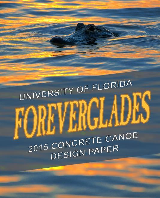
3 Aesthetic Paste Structural Ribs Outer Layer Middle Layer Inner Layer Encompassing the nation s largest subtropical wetland, Everglades National Park provides sanctuary for thirty-six protected animal species across nearly 1.5 million grassy acres in south Florida. The natural, pulsing surface water flow of the larger Everglades basin has been increasingly disrupted due to land development since the late 1800s. While it was human intervention that originally altered the flow balance, today, a more holistic engineering mentality is employed to remedy past oversights. The Comprehensive Everglades Restoration Plan (CERP) leads the effort to protect and preserve the water resources of the Everglades. Located several hundred miles to the north in Gainesville, the University of Florida (UF) has created research and extension programs to address these pressing issues. These programs aim to enhance the quality of the ecosystem and improve the abundance and diversity of native species, while also accommodating urban and agricultural water demands. As one of the most comprehensive and academically diverse public universities in the nation, UF serves more than 50,000 students annually with 16 colleges and more than 150 research centers and institutes (University of Florida (a) 2014). The UF Concrete Canoe Team, competing in one of the largest ASCE conferences, has placed 1 st in the Southeast Region the last three years and finished 12 th (AcceleGator, 2014), 3 rd (ConquistaGator, 2013), and 5 th (VindiGator, 2012) at the national level. The UF Team began its season by moving production from a satellite facility to an on-campus research laboratory. The space proved to be effective for recruitment purposes, drawing in a larger, younger team than in previous years. With youth came inexperience, prompting captains, with the help of team veterans, to formally draft best management practices to guide future teams. Proximity to numerous active research projects allowed the team to better utilize university resources. With the move, many construction and mix design techniques were improved in order to meet space constraints and ensure safety of the team members. Outside of the lab, the paddling team was committed to kneeling in all five races in an effort to maximize its competitive advantage. Accordingly, the hull design was developed to enhance paddler stability without impeding maneuverability. The concrete mix design focused on improving tensile strengths while incorporating new materials to create a low density mix. In an effort to improve upon previous teams final product scores, a schedule was created which dedicated more time to construction planning and visual display fabrication. Emphasis was placed on uniform gunwale thickness when designing the canoe form. To enhance aesthetic quality, the team integrated a threedimensional cast concrete alligator, both an Everglades native and the UF mascot, into the canoe s interior surface. To pay tribute to this marvel of nature and bring awareness to the effort to preserve the diverse ecosystem of the Everglades, UF proudly captures the beauty of this river of grass with its 2015 canoe: ForeverGlades. Maximum Maximum 22.0 ft. Length Width 26.0 in. Maximum Average 13.5 in. Height Thickness in. Weight 178 lb Colors Blue, Green, Tan, Yellow Reinforcement Carbon Fiber Mesh with Kevlar Weave Wet Unit Weight 50.5 pcf Oven Dried Unit Weight 40.6 pcf Compressive Strength 1,512 psi Tensile Strength 196 psi Wet Unit Weight 54.2 pcf Oven Dried Unit Weight 50.3 pcf Compressive Strength 2,148 psi Tensile Strength 282 psi Wet Unit Weight 49.5 pcf Oven Dried Unit Weight 40.7 pcf Compressive Strength 1,350 psi Tensile Strength 129 psi Composite Flexural Strength 1,272 psi Wet Unit Weight 55.2 pcf Oven Dried Unit Weight 52.7 pcf Compressive Strength 1,666 psi Tensile Strength 271 psi Wet Unit Weight pcf Oven Dried Unit Weight pcf Compressive Strength N/A Tensile Strength N/A Table 1: ForeverGlades Concrete Properties

4 A single head captain, acting as the project manager, took on the tasks of recruitment, budgeting, scheduling, and delegating for the ForeverGlades team. To complete the team, five captains were selected as project engineers to lead concrete mix design, hull design/structural analysis, visual design, construction, and paddling. Similar to that used by CERP, an adaptive management approach allowed the team to monitor progress and make the appropriate changes required to meet prescribed goals. Risk management was ensured by pairing veterans with inexperienced team members for construction processes, and quality control was supplemented by using external resources to help critique the design paper. Quality assurance was provided throughout the project by requiring the captains to submit progress reports and schedules at the beginning of each week to ensure that tasks followed the master schedule created by the project manager Using this master schedule, captains adhered to a critical path rooted in team historical data and planned improvements. This critical path included hull design selection, mold completion, practice canoe completion, and competition canoe completion. Major milestones not included on the critical path consisted of mix design finalization, selection of the paddling team, and completion of the design paper. These milestones were determined based on past experience and accomplished through clear and constant communication as well as timeline awareness among all captains. The ForeverGlades team understood the benefits that fabricating both a practice and a competition canoe would provide for quality assurance and educating a young team. In order to ensure there was sufficient time to design, place, and cure two concrete canoes, the schedule for structural analysis, hull design, mold construction, and mix design was rigorous and closely followed. With the donation of nearly all concrete materials and admixtures, creating a second canoe added a minimal cost of $600 to the ForeverGlades budget. The practice canoe allowed 18 newly-recruited members to become familiar with the precision required during the placement process. Additionally, the team had the opportunity to test new construction and mix design techniques to mitigate errors before the competition canoe placement one month later. Efficiency in time management and the donation of a second shotcrete gun allowed for a reduction of 75 person-hours from the placement of the practice canoe to the competition canoe. Overall, the team put in over 2,800 person-hours designing, testing, and constructing ForeverGlades (Figure 1). Figure 1: ForeverGlades Person-Hours Before using the lab, each team member was required to attend an informative, concrete canoespecific safety training session, as well as complete 12 hours of online safety courses through the University. After the initial session, the team was instructed on each tool used in the lab to ensure competence and safety at all times. Those working with concrete materials were required to read material safety data sheets for the materials and personal protective equipment was required and supplied in all areas of the lab. The team worked hand-in-hand with the laboratory staff to guarantee appropriate handling of tools and materials. The operational budget for all necessary material procurement and construction processes of the canoe was set at $4,800. Since no financial assistance is received from the University itself, the team sought to fundraise through engineering firms and UF Concrete Canoe alumni directly. Since the team was fortunate enough to receive several material donations for the concrete mix design as well as colored sealer, construction and visual display components were left to bear the brunt of the canoe completion cost. Over $9000 was raised during the year to cover project expenses, travel costs, and registration fees which allowed for a substantial sum to be allocated to the future team. Finally, a strict paddling regimen was overseen, incorporating two gym sessions and two mandatory lake practices per week beginning in the fall. The team benefitted immensely from the opportunity to practice in the chosen hull design (the practice canoe) in the months leading up to the competition.

5

6 The ForeverGlades hull design team drew upon well documented and successful hull forms from past years to maintain a tradition of excellence in design. Obtaining feedback from last year s paddlers and using AcceleGator as a baseline, the team focused on refining the hull for improved race performance. Design goals were geared toward balancing straight-line speed and maneuverability, while improving stability in order to accommodate the kneeling paddling style. The design team sought to increase straight line speed by reducing the hull s wave-making resistance. This can be achieved by maximizing waterline length; however, with the canoe length constrained at 22 ft. (ASCE/NCCC 2015), other parameters had to be altered. The bow rocker was decreased from 5.5 in. to 4 in. This decrease in curvature reduced maneuverability which, in turn, increased tracking. To compensate, the rocker curvature was maintained along the hull bottom, providing less lateral resistance and promoting boundary layer cohesion. This combination maintained sufficient maneuverability while minimizing wave-making resistance (Winters 2006). The continued use of a transom stern this year also helped to maximize waterline length. This truncation allows flow to continue as if the canoe actually extended out to a point as shown in Figure 2. The increased effective waterline length results in a decrease in form resistance. Proper separation was achieved through correct sizing of the truncation by maintaining the Froude numbers of at least 2.0 (Maki et al. 2005). Figure 2: Transom Stern Flow Separation The ForeverGlades hull profile was flattened slightly, which enhanced the initial stability of the canoe (Gullion 1994). The need for improved stability was expressed by paddlers in order to more comfortably and effectively deliver power while kneeling. Wave-making resistance tends to increase with a larger surface area; however, with a flatter bottom, the sanding process can be carried out more accurately, giving the hull a smoother finish and reducing friction drag when compared with AcceleGator (University of Florida (b) 2014). A 15 degree raked bow, added for aesthetic purposes, decreased the amount of deadwood in the bow, further reducing wetted surface area and friction drag. From previous years scale model test data, this bow angle was determined to be the most efficient (University of Florida 2007). Hulls were designed using FREE!ship (Timoshenko 2013) and compared using the fluid dynamics program, Mitchlet (Lazauskas 2013). This was done to accurately determine the designs with the least wave resistance. Resistance was analyzed for hull speeds ranging from 1 to 6 knots (1.69 to ft./s), the estimated maximum speed during the co-ed sprint race. From these results, 4 final designs were tested for straight-line speed and maneuverability. Scale models at 1:6 size were milled using a computer numerical controlled (CNC) machine at an on-campus fabrication center. This scale was chosen to best maintain model similitude, matching Froude numbers while remaining in an acceptable range of Reynolds number. Based on design criteria and scale model test performance which balanced speed and turning, a final hull was selected with a shallow arch bottom, 22-ft. length, 26-in. beam, and 2-in. transom stern. ForeverGlades improves upon last year s straightline speed while maintaining comparable turning ability and meeting all design goals. Structural analysis was performed with the purpose of determining the critical tensile and compressive strengths required for the hull to undergo various predetermined loading cases. The loading conditions considered included the twomale loading, four person loading, and the demolding, transportation, and display of the canoe. Analysis was performed longitudinally along the length of the canoe and laterally along the beam of the hull to obtain critical values. For each orientation of analysis, the canoe was assumed to be a two-dimensional beam.
7 For longitudinal analysis, the hull was divided into 3-in. sections to evaluate the location of the maximum moment. Assuming rectangular sections for ease of calculation, the moment of inertia for each was determined. A program in Excel (Microsoft 2010) was developed to find the shear forces and bending moments along the beam using the principles of Euler-Bernoulli beam theory. Figure 3 shows the free body diagram used to analyze the canoe in the longitudinal direction. Figure 3: Free Body Diagram for Men s Sprint For racing conditions, the canoe was modeled to be continuously supported by the buoyant force, which acts equal and opposite to that of the weight of water displaced. Using displacements for specific loading cases, the draft was determined from the program FREE!ship (Timoshenko 2013). From the draft, the submerged volume of each section was calculated and multiplied by specific weight of water to obtain the buoyant force. The weight of the canoe, assumed from last year s canoe as 160 lb, was uniformly distributed over its length. Point loads of 160 lb and 140 lb represented the male and female paddlers, respectively. These values were then increased by 25% to 200 lb and 170 lb. This increase accounted for dynamic load amplification during the races (Paradis and Gendron 2006). The loads were placed 4 ft. and 18 ft. from the bow, simulating paddler placement for the men s races. Two female loads were added at 8 ft. and 14 ft. for the co-ed sprint. Analysis of the display scenario resulted in the determination of the optimal placement of two stands at 4 ft. and 17 ft. from the bow. The two-male loading scenario was found to produce the critical loading case, with a maximum negative bending moment of 9,464 in.-lb located 11 ft. from the bow. Using the location of the section s neutral axis and the principle of flexure, the tensile and compressive stresses in the section were calculated to be approximately 84 psi and 258 psi, respectively. Based on the concrete properties from the previous year, the minimal acceptable tensile and compressive strengths were determined to be 100 psi and 1,300 psi. These strengths provide a longitudinal factor of safety of 1.2, sufficient capacity for tolerating the stresses induced from the considered loading cases. During bow-initiated turns, a paddler s hips often push against the top of the gunwales. A lateral analysis of the hull was required to determine these resulting stresses (Figure 4). The co-ed sprint race was the critical loading case for lateral analysis due to larger forces against the gunwales and the larger buoyant force due to the weight of the four paddlers. A force of 200 lb was assumed to act on the gunwales from a shift in the paddlers weights, causing a moment of 2,362 in.-lb located at the chine. The canoe was assumed to be in. thick with a layer of carbon fiber mesh between each of the three layers of concrete. The carbon fiber mesh reinforcement provides a tensile strength of 512 ksi and elastic modulus of 33.4 Msi (TorayCA 2014). Using the transformed area method, the moment allowed by the reinforced concrete is 294 in.-lb, significantly lower than the required strength. Figure 4: Free Body Diagram for Lateral Analysis To increase the maximum allowable moment, three 1 in. deep structural ribs were added one behind the bow paddler, one amidship, and one toward the stern providing enough room for the aftmost paddler. The added ribs raised the maximum allowable moment to 6,440 in.-lb, which increased the overall lateral factor of safety to 2.73 and assuaged concerns over paddler hip impacts.


8 As the campaign began, the mix design team resolved to further build upon the success achieved in the previous year. To this end, the ForeverGlades team looked to improve the compressive, tensile, and flexural strengths of the canoe, while simultaneously recapturing the low unit weights and smooth outer finishes of years past. In doing so, the team was able to create mixes which surpassed calculated structural requirements by a large degree. The mix design used in the inner layer of the previous year s canoe, AcceleGator, was recreated as a baseline for the mix design process as it achieved high strength and aesthetic appeal. With 14-day compressive and composite flexural strengths of 1,638 and 1,194 psi, respectively, the control mix performed satisfactorily with a wet unit weight of 47.7 pcf and a water-to-cementitious materials ratio (w/cm) of 0.40 (University of Florida (b) 2014). Nonetheless, ForeverGlades mix design team set out to make substantial improvements, designing, testing, and analyzing over four dozen mixes through the process shown in Figure 5. After initially curing at room temperature for three days, the specimens were placed in a 105ºF limewater bath for an additional 11 days. This 14-day period was chosen to maintain the timeframe desired for the number of tests to be completed during the development stage. After curing, 2 in. by 4 in. cylindrical specimens were tested in compression in general accordance with ASTM C39. Tensile briquette specimens were created and tested in accordance with ASTM C307, and composite panels were tested in third-point flexure using a modified version of ASTM C78 (Figure 6). This modified technique was employed Figure 5: Iterative Process for Concrete Mix Design since the panels were too thin to conform to the exact requirement of the standard. In order to maintain workability while improving upon AcceleGator s strength-to-weight ratio, the ForeverGlades team focused primarily upon cementitious materials and proportions. Given the lack of limitations on the proportion of portland cement in this year s competition, complete replacement of this material was considered. Portland cement content was lowered in steady increments until it constituted zero percent of the cementitious material. However, once the proportion of portland cement fell below 25% of the mix s total cementitious material, relative strength and bond properties were drastically reduced. Decreasing the amount of portland cement required the mix to utilize ground blast furnace slag. Ground blast furnace slag s propensity for strength gains under elevated curing temperatures contributed to strength increases observed during testing (Ferraro 2009). Figure 6: Third- Point Flexure Test on Composite Panel The team introduced two new cementitious materials, VCAS 160 and white portland cement to the mix design regimen for consideration. Often considered very similar to gray portland cement, white portland cement was a novel addition for ForeverGlades mix team due to its light color and its high potential for reactivity with pozzolans, which stems from its low ferrite content (Lubeck et al. 2011). VCAS 160, a recycled glass powder, was tested for its ability to lower water demand which allows for the pozzolanic material to be used in concrete with low w/cm (Hossain et al. 2008). Ultimately, VCAS 160 was selected over two alternatives, Class F fly ash and metakaolin. The three alternatives were extensively tested in several variations and the highest compressive strength resulted from a complete replacement of metakaolin and fly ash with VCAS 160. Furthermore, its white color made it an attractive candidate for the ForeverGlades team, as neither the off-white metakaolin nor the gray fly ash could foster lighter-
9 tinted mixes; which was part of the team s aesthetic strategy of creating a lighter-colored canoe for sealing purposes. Of significant concern noticed by the AcceleGator team was the continued propagation of cracks on the hull, an issue which arose late in the 2014 season. In order to increase tensile strength, the ForeverGlades team employed basalt fibers. Basalt fibers are lightweight fibers made from molten rock with a tenacity higher than that of steel. They improve flexural strength, do not absorb water, and have the same coefficient of thermal expansion as concrete (Cheng Concrete 2014). Although basalt fibers have a lower clumping risk when mixed, they still leave the shotcrete gun vulnerable to clogging. To offset this risk and remain in accordance with ASTM C1116, the well-staffed ForeverGlades team dedicated hundreds of hours to the separation of fibers from one another. Several methods, including the use of compressed air, were tested to increase the efficiency of separating fibers, but hand separation proved most effective. As a result of separation, the individual fibers assimilated themselves more fluidly into the mix, and issues with clumping and workability were largely overcome. Furthermore, the fibers lent significant tensile strength to the specimens tested, providing increases of up to 137% over control mixes. SikaLatex R was used in previous years as a polymer modifier. Styrene-butadiene rubber (SBR) latex, a newly-donated material, was tested as a potential replacement for SikaLatex R due to its popularity with other successful teams. A direct replacement of SBR latex for SikaLatex R in a control mix led to higher workability and a lower water demand, both of which were desirable properties. However, SikaLatex R was still used for the middle layer of ForeverGlades for its airentraining ability; further air entrainment was achieved through the use of Darex AEA. This middle layer mix provided desirable strengths and unit weights for this year s team. Unfortunately, SikaLatex R introduced voids and an undesirable finish. For this reason, it was replaced with SBR latex in the visible layers and structural ribs. To achieve the level of workability necessary for shotcreting, ADVA Cast 600, a superplasticizer, was used in conjunction with WRDA 60, a midrange water reducer. Varying levels of these plasticizers were employed in each layer, accounting for differences in placement method, aggregate gradation, and fiber content. Efforts to prevent drying of mixes prior to placement were aided by the use of V-MAR 3, a rheologymodifying admixture. AcceleGator s aggregate blend, developed from rigorous testing, was adopted by the ForeverGlades team in order to focus its efforts on changes in cementitious materials, fibers, and admixtures. The five aggregates, three sizes of Poraver, S38 and K15 glass microspheres allowed for superior gradation and strength-to-weight ratios. For the two surface layers, increased quantities of S38 and K15 were utilized in lieu of the largest-sized Poraver, creating a smooth, lightweight mix. Aiming to control quality and consistency of test results, the mix team decided to forgo the traditional compaction method of hand tamping specimens, employing a vibrating table during casting. Control mixes, which were produced by both manual and mechanical compaction, showed a stark contrast between the methods. Specimens created using the vibrating table, including both cylinders and briquettes, saw significant decreases in void quantity and size, leading to increased tensile and compressive strengths. Most importantly, the use of the vibration table also standardized the samples made by eliminating human error introduced by tamping previously observed. This produced better comparisons between mixes and a more accurate representation of the final concrete product used in the canoe. After setting, demolding, and curing for 14 days, the bearing surfaces of the cylindrical specimens were lightly sanded using a belt sander to remove large deformations. New for this year, unbonded neoprene caps per the specifications of ASTM 1232 were used during the compressive strength testing (Figure 7). These caps allowed for consistent comparisons between specimens by creating a smooth, parallel bearing surface perpendicular to the applied axial load during compressive strength testing (NRMCA 2014).

10 A new procedure for mixing fresh concrete was undertaken this year to increase slump and prevent mixes from drying out too quickly on long placement days. As suggested by UF faculty, all wet materials were added to the mixing bowl after dry mixing for 45 seconds, as opposed to adding water reducers after an initial wet mixing period. Fresh mixes were noticeably more workable, showing an increase in slump. Actual unit weights also proved more consistent with predicted unit weights, suggesting that Darex AEA was most efficacious when added alongside the other wet materials. Figure 7: Neoprene Caps for Compression Test The ForeverGlades team was determined to incorporate sustainability into every aspect of the project. In the past, cleaning of mixing equipment was done with a hose in a constantly draining basin using at least 5,000 gallons of water per placement day. As part of this year s effort, shop towels were replaced with cloth towels, and water usage was closely monitored and limited on both placement days. A basin containing 45 gallons of water was used for cleaning large equipment while a five gallon bucket was used to clean syringes, small buckets, and other small batching tools. It was determined that merely 140 gallons of water were used for cleaning on each placement day. The glass particles constituting all sizes of Poraver aggregate are recycled, providing a level of environmental sustainability mirrored by the recycled glass powder of VCAS 160. Ground blast furnace slag represents another sustainable material, as its use in concrete precludes its environmentally-harmful disposal as an industrial by-product. Substantial donations were secured for many of the materials, including white portland cement, slag, S38, K15, and all admixtures, save SikaLatex R. Economic sustainability was thereby maximized for the mix design phase of the project. Like many of its predecessors, ForeverGlades includes three layers of concrete. In previous years, the larger-sized aggregates would become dislodged during troweling, producing a rough surface. This year, a mix excluding larger-sized aggregates was used for both the inner and outer layers, rather than just the outermost layer of the canoe, as was the case in AcceleGator. This omission allowed for an increase in surface area and decrease in void quantity, ultimately creating a more aestheticallypleasing canoe with decreased drag. The mix design including all sizes of Poraver proved to be strongest in tension and compression; it was therefore used in the middle layer and structural ribs to provide flexural support throughout the canoe. Finally, the inner two layers and the ribs contain basalt fibers to aid in tension and flexure. Kevlar impregnated carbon fiber mesh was used as structural reinforcement and was embedded between each layer of the canoe. Strips of the mesh were also placed in between two lifts of concrete when hand-placing the structural ribs. The final mixes employed in ForeverGlades (shown in Table 2) developed strengths that exceeded the requirements set by the structural anaylsis while meeting goals set for hue and unit weight. Concrete Properties *Strengths Taken at Inner Middle Outer Structural Aesthetic AcceleGator AcceleGator 14 Days Layer Layer Layer Ribs Paste Inner Layers Outer Layer Wet Unit Weight 50.5 pcf 54.2 pcf 49.5 pcf 55.2 pcf pcf 47.7 pcf 49.3 pcf Dry Unit Weight 40.6 pcf 50.3 pcf 40.7 pcf 52.7 pcf pcf 36.1 pcf 35.2 pcf w/cm Compressive Strength* 1,512 psi 2,148 psi 1,350 psi 1,666 psi N/A 1,638 psi 1,339 psi Tensile Strength* 196 psi 282 psi 129 psi 271 psi N/A 121 psi 101 psi Basalt Chopped Fibers Yes Yes No Yes No No No Latex SBR SikaLatex R SBR SBR No SikaLatex R SikaLatex R Flexural Strength* 1,272 psi N/A N/A 1,194 psi Table 2: ForeverGlades Concrete Properties Compared to AcceleGator


11 With the move to an on-campus facility, the ForeverGlades team had to make several adjustments in order to better operate in the new space. The major change involved making the canoe form mobile in order to reduce spatial and logistical problems within the lab. This meant eliminating the table on which the form had been built in the past and constructing the form directly on a steel beam. Heavy-duty casters were attached to the beam, allowing it to be easily maneuvered. Eliminating the table surface also cut this year s plywood use in half. The form s mobility allowed sanding to be done outside of the lab, reducing respiratory concerns within the team s confined area. Additionally, this enabled the team to accommodate the everchanging research projects within the shared lab space. Based on the team s experience level and the ability to better regulate layer thickness while shotcreting, a male form was chosen for ForeverGlades. Rather than having it CNC milled, the form was crafted by hand. This method allowed the team to stay within its budget and familiarize newer team members with the level of precision that would later be required during placement. Instead of foam, the team chose to use wood as the primary material for constructing the form. This choice was motivated by the sustainable harvesting of the available lumber and the ability to reuse pieces of the previous year s form. Cross sections at 1 ft. increments were obtained from the design software, then printed and cut from ¾ in. plywood. The cross sections were cut with an added rectangular piece at their bases, allowing them to fit directly into the beam and included a lip at the gunwales. This lip was designed at the desired thickness of the canoe to ensure uniformity when troweling on placement day. The steel beam contains holes every 4 in. Figure 8: Cross Sections Supported and Bolted to Beam on-center, enabling better accuracy in placing the sections at 1 ft. increments. The rigidity of the beam also aided in keeping the cross sections aligned. Plywood spacers and wooden triangles braced each side of the sections and were bolted to the beam (Figure 8). Once every section was in place, a transit level was used to align each one along the hull s centerline. The construction team nailed ½ in. wide plywood strips to the edges of the cross sections, connecting them and forming the canoe s curved shape. A 5/16 in. thickness was chosen for these strips because it provided enough flexibility to follow the hull s contours but enough rigidity to resist deflection during sanding. Once completed, the team used a belt sander to make an initial pass over the entire form before applying Bondo to fill in gaps and depressions. Repeated sanding and Bondo applications resulted in a smooth, even form surface. The entire form was then coated in a laminating resin to waterproof the wood. When the resin was completely cured, precut adhesive foam designs were applied to the form in order to create an inlaid effect on the concrete. Insulation foam was used instead of wood to create the finer details of the hull s shape. The bow and stern sections of the hull were sculpted from layered foam using a variable speed orbital sander to achieve the shape prescribed by the FREE!ship (Timoshenko 2013) file. The three structural rib sections were carefully handsanded to achieve roughly the desired profile. A meticulous application of Bondo provided the freedom to create the preferred trapezoidal shape (Figure 9). The chamfered design was implemented to ease demolding and mitigate stress concentrations by reducing sharp inside corners. Figure 9: Structural Rib Form The ForeverGlades team made it a priority to optimize the lengthy placement day process where possible. The practice placement day was scrutinized by team captains, and changes were implemented for competition placement day. Competition placement day proved to be more efficient as a second shotcrete gun was donated and twice as many trowelers were trained to smooth the


12 fresh concrete. This allowed the team to work on larger sections of the canoe more efficiently and finish troweling before the concrete became unworkable. The team began placement day by thoroughly applying vegetable oil to the form as a natural release agent. Next, two layers of concrete were hand-placed in each rib, with a strip of carbon fiber mesh reinforcement embedded between them. Immediately thereafter, the first layer was shotcreted and troweled to a ruled thickness of 1/8 in.; marked pins were used by trowelers to ensure a consistent thickness throughout each layer. Once complete, carbon fiber mesh was placed over the entire canoe and embedded into the first layer by hand. The next layer was also applied at 1/8 in., after which a second sheet of carbon fiber was embedded into the canoe. Layer thickness was carefully monitored at the gunwale lip. A thicker, final layer was applied at 3/16 in. to allow the team to more effectively sand away exterior imperfections while maintaining the final thickness of 3/8 in. On this layer, the gunwale lip allowed team members to trowel straight up from its edge, ensuring regularity along the length of the canoe. Extra care was taken in finishing the outer layer to minimize the amount of time needed later for sanding. The canoe was then covered in plastic for the next three days to retain moisture as the concrete set. A new, modular curing tank was constructed to maximize the efficiency of the team s limited lab space. Since the tank could be easily disassembled, the side panel was removed and the entire form was rolled into the tank, while still attached to the beam. A water heater and soaker hose were used over the entire canoe to recirculate water infused with calcium hydroxide to aid in the curing process (Figure 10). A double layer of burlap ensured that the canoe s Figure 10: Initial Curing with Heated Soaker Hose surface remained moist. With the tank acting as a catch basin, there was minimal water loss during this phase of curing. At the end of the initial 14-day curing, the form was removed from the tank, and the canoe was demolded. This time frame simulates the strength and age at which specimens were tested during the design phase. Compressed air was employed for the first time this year to separate the concrete from the form, several team members were able to lift the canoe off of the wooden form. The foam sections used to shape the bow and stern were left in the canoe as flotation. The curing tank was then reassembled, filled with limewater, and the canoe was submerged for an additional two weeks at 135 ºF to complete curing. This system was able to achieve a higher temperature than first anticipated, allowing greater opportunity for strength gain than test specimens (NRMCA 2006). At the conclusion of the curing process, the canoe was removed from the tank, and concrete was handplaced to cover the flotation at the bow and stern. Minor air voids in the hull s interior were also filled in at this time. The interior and exterior of the canoe were carefully hand sanded to remove imperfections and create the optimum surface for applying sealer. Long, wooden sanding blocks were used to mitigate waviness along the outside walls of the canoe. Incrementally moving from 100 to 300 grit sandpaper helped the team achieve the finest finish for sealer. Figure 11: Aesthetic Alligator in Practice Canoe To better integrate this year s theme into the construction of ForeverGlades, the team decided to incorporate a three-dimensional alligator on the interior of the hull (Figure 11). The three portions of the alligator s body were sculpted from clay, and a corn starch and silicone mixture was used to create flexible molds. To maintain continuity with the canoe, the fine, inner layer mix was used to cast the alligator. A special mix was created to bond it to the hull. The alligator was then strategically placed in the canoe based upon aesthetics and paddler safety. ForeverGlades was then thoroughly cleaned before carefully applying colored sealer.
13 ForeverGlades Schedule ID Task Name Baseline Start Baseline Finish Actual Start Actual Finish August 1 September 1 October 1 November 1 December 1 January 1 February 1 March 1 April 1 May 1 June 1 July 1 8/3 8/17 8/31 9/14 9/28 10/12 10/26 11/9 11/23 12/7 12/21 1/4 1/18 2/1 2/15 3/1 3/15 3/29 4/12 4/26 5/10 5/24 6/7 6/21 1 Project Management Mon 8/25/14 Fri 3/20/15 Sat 8/16/14 Sun 3/22/15 2 Rules & Regulations Released Mon 9/1/14 Mon 9/1/14 Wed 9/10/14 Wed 9/10/14 3 Create Budget Mon 8/18/14 Mon 8/25/14 Sat 8/16/14 Mon 8/25/14 4 Project Scheduling Mon 8/25/14 Thu 8/28/14 Thu 8/21/14 Fri 8/29/14 5 Fundraising Mon 8/25/14 Sat 3/21/15 Wed 10/1/14 Sun 3/22/15 6 Theme Development Thu 9/18/14 Fri 10/17/14 Wed 9/17/14 Fri 11/14/14 7 Canoe Development Fri 8/29/14 Wed 3/18/15 Mon 8/25/14 Wed 3/18/15 8 Mix Design Fri 8/29/14 Tue 11/18/14 Mon 8/25/14 Wed 11/26/14 9 Procure Materials Fri 8/29/14 Thu 10/16/14 Mon 8/25/14 Fri 10/10/14 10 Test Cementitious Materials Tue 9/16/14 Sat 10/11/14 Fri 10/10/14 Fri 10/24/14 11 Test Fibers Fri 10/10/14 Fri 10/24/14 Mon 10/27/14 Fri 10/31/14 12 Adjust w/cm Mon 10/27/14Mon 11/3/14 Sat 11/1/14 Fri 11/7/14 13 Test Final Mix Choices Mon 11/17/14Fri 11/21/14 Fri 11/21/14 Fri 11/21/14 14 Select Final Mix Design Mon 11/24/14Mon 11/24/14Wed 11/26/14 Wed 11/26/14 15 Structural Analysis Mon 9/1/14 Sun 10/12/14 Wed 10/1/14 Fri 11/14/14 16 Research 2-D Methods Wed 10/1/14 Sat 10/25/14 Wed 10/1/14 Sat 10/25/14 17 Develop Analysis Method Wed 10/1/14 Sat 10/25/14 Wed 10/1/14 Sat 10/25/14 18 Complete Analysis Sat 10/25/14 Sun 11/23/14 Sat 10/25/14 Fri 11/14/14 19 Hull Design Mon 8/18/14 Sun 10/12/14 Mon 8/25/14 Mon 10/6/14 20 Research Hull Design Mon 8/18/14 Thu 9/25/14 Mon 8/25/14 Thu 9/4/14 21 Software Modeling Mon 8/18/14 Tue 9/30/14 Thu 9/11/14 Tue 9/23/14 22 CNC Scale Models Tue 9/30/14 Wed 10/1/14 Wed 9/24/14 Thu 9/25/14 23 Test Scale Models Fri 10/3/14 Sun 10/5/14 Fri 9/26/14 Sat 9/27/14 24 Hull Selection Mon 10/6/14 Mon 10/6/14 Sat 10/4/14 Mon 10/6/14 25 Hull Form Construction Mon 8/25/14 Sat 12/6/14 Mon 9/1/14 Sun 1/11/15 26 Determine Construction Methods Mon 9/1/14 Fri 10/17/14 Mon 9/1/14 Tue 10/14/14 27 Procure Materials Mon 8/25/14 Thu 1/8/15 Mon 9/1/14 Sun 1/11/15 28 Cut and Install Cross-Sections Tue 10/21/14 Sat 10/25/14 Tue 10/28/14 Tue 11/4/14 29 Install Wood Strips Tue 10/28/14 Sat 11/1/14 Wed 11/5/14 Wed 11/12/14 30 Construct Bow and Stern Sections Tue 10/14/14 Sat 10/25/14 Tue 11/11/14 Mon 12/1/14 31 Apply Automotive Body Filler Tue 11/4/14 Sat 11/15/14 Wed 11/12/14 Mon 12/1/14 32 Apply Fiberglass Resin Mon 12/8/14 Mon 12/8/14 Mon 12/8/14 Mon 12/8/14 33 Form Complete Wed 12/10/14Wed 12/10/14Wed 12/10/14 Wed 12/10/14 34 Practice Canoe Pour Mon 11/17/14Thu 12/11/14Mon 12/1/14 Fri 1/30/15 35 Batch Dry Mix Materials Mon 11/17/14Fri 12/5/14 Mon 12/1/14 Wed 12/10/14 36 Pre-Pour Day Meeting Sun 12/7/14 Sun 12/7/14 Sun 12/7/14 Sun 12/7/14 37 Pour Practice Canoe Thu 12/11/14 Thu 12/11/14 Thu 12/11/14 Thu 12/11/14 38 Soaker Hose Curing Sun 12/14/14 Sat 12/27/14 Sun 12/14/14 Sun 12/28/14 39 Remove From Form Sat 12/27/14 Sat 12/27/14 Sun 12/28/14 Sun 12/28/14 40 Cure Practice Canoe Sun 12/14/14 Sat 1/11/14 Sun 12/14/14 Wed 1/21/15 41 Sand Practice Canoe Mon 1/12/15 Fri 1/16/15 Thu 1/22/15 Tue 1/27/15 42 Seal and Stain Concrete Mon 1/19/15 Fri 1/23/15 Tue 1/27/15 Wed 1/28/15 43 Practice Canoe Complete Sun 1/11/15 Sun 1/11/15 Thu 1/29/15 Thu 1/29/15 44 Transport Practice Canoe to Lake Sun 1/25/15 Sun 1/25/15 Fri 1/30/15 Fri 1/30/15 45 Competition Canoe Pour Tue 1/6/15 Sat 1/17/15 Tue 1/6/15 Sat 1/17/15 46 Refurbish Mold Mon 1/5/15 Thu 1/15/15 Tue 1/6/15 Fri 1/16/15 47 Apply Inlays Thu 1/15/15 Thu 1/15/15 Fri 1/16/15 Fri 1/16/15 48 Batch Dry Mix Materials Tue 1/6/15 Fri 1/16/15 Tue 1/6/15 Fri 1/16/15 49 Apply Mold Release Sat 1/17/15 Sat 1/17/15 Sat 1/17/15 Sat 1/17/15 50 Cut Carbon Fiber Sat 1/17/15 Sat 1/17/15 Sat 1/17/15 Sat 1/17/15 51 Pour Competition Canoe Sat 1/17/15 Sat 1/17/15 Sat 1/17/15 Sat 1/17/15 52 Pour Samples for Testing and Submi Sat 1/17/15 Sat 1/17/15 Sat 1/17/15 Sat 1/17/15 53 Finish Competition Canoe Sat 1/10/15 Wed 3/18/15 Tue 1/20/15 Wed 3/18/15 54 Soaker Hose/Wet Burlap Curing Tue 1/20/15 Sat 1/31/15 Tue 1/20/15 Sat 1/31/15 55 Remove From Form Sun 2/1/15 Sun 2/1/15 Sun 2/1/15 Tue 2/3/15 56 Heated Water Tank Curing Sun 2/1/15 Sun 2/15/15 Wed 2/4/15 Wed 2/18/15 57 Hull Exterior Sanding Mon 2/16/15 Mon 2/23/15 Thu 2/19/15 Fri 2/27/15 58 Stain and Seal Concrete Tue 2/24/15 Sat 3/14/15 Tue 3/3/15 Sun 3/15/15 59 Competition Canoe Complete Sat 3/14/15 Sat 3/14/15 Wed 3/18/15 Wed 3/18/15 60 Display Fri 10/17/14 Mon 2/9/15 Mon 11/17/14 Sat 3/14/15 61 Design Display Fri 10/17/14 Fri 1/30/15 Mon 11/17/14 Mon 3/2/15 62 Build Canoe Stands Fri 10/17/14 Sun 2/1/15 Mon 12/1/14 Fri 3/13/15 63 Build Table Display Fri 10/17/14 Fri 1/30/15 Mon 1/12/15 Wed 2/25/15 64 Build Cutaway Section Mon 1/26/15 Sat 3/14/15 Fri 2/20/15 Sat 3/14/15 65 Academics Sun 12/14/14 Wed 3/18/15 Sat 12/20/14 Wed 3/18/15 66 Design Paper Fri 12/19/14 Fri 2/13/15 Sat 12/20/14 Thu 2/26/15 67 Write Rough Draft Sun 12/14/14 Sat 1/17/15 Sat 12/20/14 Mon 1/5/15 68 Edit Rough Draft Sat 1/17/15 Tue 2/10/15 Tue 1/6/15 Wed 2/25/15 69 Print Paper Thu 2/12/15 Thu 2/12/15 Wed 2/25/15 Wed 2/25/15 70 Submit Paper Mon 2/23/15 Mon 2/23/15 Thu 2/26/15 Thu 2/26/15 71 Oral Presentation Sat 2/14/15 Thu 3/19/15 Sun 1/18/15 Wed 3/18/15 72 Write Script Sat 2/14/15 Sat 2/28/15 Sun 1/18/15 Fri 3/6/15 73 Know Script and Study Questions Mon 3/2/15 Thu 3/19/15 Wed 3/4/15 Wed 3/18/15 74 Create Presentation Sun 1/18/15 Fri 2/27/15 Sun 1/25/15 Fri 3/6/15 75 Rehearsal Sat 2/28/15 Thu 3/19/15 Sat 3/7/15 Wed 3/18/15 76 Athletics Sun 9/7/14 Sun 3/23/14 Sun 9/7/14 Sun 3/15/15 77 Paddling Practice Sun 9/7/14 Sun 11/9/14 Sun 9/7/14 Sun 11/9/14 78 Select Paddling Team Sun 11/9/14 Sun 11/9/14 Mon 11/10/14 Mon 11/10/14 79 Team Practice Mon 11/3/14 Sun 3/15/15 Sat 11/15/14 Sun 3/15/15 80 Southeast Regional Conference Thu 3/19/15 Sat 3/21/15 Thu 3/19/15 Sat 3/21/15 81 Preparation for NCCC Mon 3/23/15 Thu 6/18/15 Sat 4/4/15 Thu 6/18/15 82 Revise Design Paper Mon 3/30/15 Fri 5/15/15 Mon 4/6/15 Tue 5/12/15 83 Submit Design Paper Tue 5/12/15 Fri 5/15/15 Tue 5/12/15 Tue 5/12/15 84 Practice Oral Presentation Mon 3/23/15 Thu 6/18/15 Thu 4/9/15 Thu 6/18/15 85 Modify Display Materials Mon 3/30/15 Thu 6/18/15 Mon 4/6/15 Thu 6/18/15 86 Team Paddling Practice Sat 4/4/15 Thu 6/18/15 Sat 4/4/15 Sun 6/14/15 87 National Concrete Canoe Competition Sat 6/20/15 Mon 6/22/15 Sat 6/20/15 Mon 6/22/15 Project: ForeverGlades Date: 07 May 2015 Team: University of Florida Task Task Milestone Baseline Baseline Milestone Critical Critical Milestone You created this PDF from an application that is not licensed to print to novapdf printer (


 R3\" 8 9 19 10 3 7 2 Bow/Stern Endcap Support 2 Cross Section Support Gunwale Lip 10 10 3 3 SECTION B-B WIDEST")
 9 1 8 8 10 7 R4\" PRODUCED BY AN AUTODESK EDUCATIONAL PRODUCT 1' 1' 9\" 1'")
14 8 3 D1 1 5 A A FORM PLAN VIEW 6 B B 4 D1 4 2 D1 PRODUCED BY AN AUTODESK EDUCATIONAL PRODUCT 2.5" C C " 8 University of Florida American Society of Civil Engineers Concrete Canoe Team Item Qty. Component Description Cross-Section 3 4 " Plywood 3 84 Gusset Recycled 2"x4" white pine 4 3 Rib Mold Blue Extruded Polystyrene Foam 5 2 Bow/Stern Section Blue Extruded Polystyrene Foam 6 71 Aesthetic Inlay Decorative Sand-Blasting Mask 7 1 Steel Beam 2 C-Channel Beams welded together 1 Covering 1 4 " Plywood Strips, Automotive Body Filler, and Resin Coating PRODUCED BY AN AUTODESK EDUCATIONAL PRODUCT 4.0" FORM ELEVATION VIEW " 5 5 D RIB DETAIL " SECTION A-A TYPICAL SECTION FORE OF MIDSHIPS (extent of mold) R3" Bow/Stern Endcap Support 2 Cross Section Support Gunwale Lip SECTION B-B WIDEST SECTION (extent of mold) 2 7 R5" 25.33" 20.50" 1 2" Plywood 1 2" Plywood 1/8" Plywood 3 3 SECTION C-C TYPICAL SECTION AFT OF MIDSHIPS (extent of mold) R4" PRODUCED BY AN AUTODESK EDUCATIONAL PRODUCT 1' 1' 9" 1' 1' 1' 1' 1' 1' 9" 1' 1' 1' 1' 1' 9" 1' 1' 1' 8 3 FORM ISOMETRIC VIEW " 3" 3" CROSS-SECTION LAYOUT PLAN VIEW Title: Project: Drawn by: Scale: FOREVERGLADES FORM DRAWINGS 2015 UNIVERSITY OF FLORIDA CONCRETE CANOE ZACHARY PRYTULA NOT TO SCALE Date: Sheet: D PRODUCED BY AN AUTODESK EDUCATIONAL PRODUCT
15 ASCE/NCCC. (2015) American Society of Civil Engineers National Concrete Canoe Competition. Rules and Regulations. < nt_pieces/nccc-rules-and-regulations.pdf> (Feb. 18, 2015). ASTM (2010). Standard Specifications for Air-Entraining s for Concrete. C260/C260M 10a, West Conshohocken, PA. ASTM (2010). Standard Specification for Fiber-Reinforced Concrete. C1116/C1116M-10a. West Conshohocken, PA. ASTM (2010). Standard Test Method for Flexural Strength of Concrete (Using Simple Beam with Third-Point Loading). C78/C78M-10el, West Conshohocken, PA. ASTM (2012). Standard Specifications for Coal Fly Ash and Raw or Calcined Natural Pozzolan for Use in Concrete. C618 12a, West Conshohocken, PA. ASTM (2012). Standard Specification for Portland Cement. C150/C150M 12, West Conshohocken, PA. ASTM (2012). Standard Test Method for Density, Relative Density (Specific Gravity), and Absorption of Fine Aggregates. C128 12, West Conshohocken, PA. ASTM (2012). Standard Test Method for Tensile Strength of Chemical-Resistant Mortar, Grouts, and Monolithic Surfacings. C307-03(2012), West Conshohocken, PA. ASTM (2013). Standard Specification for Chemical s for Concrete. C494/C494M 13, West Conshohocken, PA. ASTM (2013). Standard Specification for Concrete Aggregate. C33/ C33M - 13, West Conshohocken, PA. ASTM (2013). Standard Specification for Latex and Powder Polymer Modifiers for use in Hydraulic Cement Concrete and Mortar. C , West Conshohocken, PA. ASTM (2013). Standard Specification for Slag Cement for Use in Concrete and Mortars. C989/C989M 13, West Conshohocken, PA. ASTM (2013). Standard Terminology Relating to Concrete and Concrete Aggregates. C125 13b,West Conshohocken, PA. ASTM (2013). Standard Test Method for Density (Unit Weight), Yield, and Air Content (Gravimetric) of Concrete. C138/C138M 13a, West Conshohocken, PA. ASTM (2014). Standard Practice for Use of Unbonded Caps in Determination of Compressive Strength of Hardened Concrete Cylinders. C1231/C1231M-14. West Conshohocken, PA. ASTM (2014). Standard Test Method for Compressive Strength of Cylindrical Concrete Specimens. C39/C39M-14, West Conshohocken, PA.
16 Cheng Concrete (2014). Cheng Concrete Exchange: Chopped Basalt Fiber. < Rebar/Chopped-Basalt-Fiber> (Dec 3, 2015). Ferraro, Christopher C. (2009). Determination of Test Methods for the Prediction of the Behavior of Mass Concrete. Doctoral Dissertation, University of Florida, Gainesville, FL. Gray Line (n.d.). Allow Your Imagination to go Wild in the Everglades. Digital image. < 5864_13/>. (Feb. 20, 2015). Gullion, L (1994). Canoeing. Human Kinetics Publishers, Champaign, IL, Hossain, A.B., Shirazi, S.A., Persun, J., Neithalath, N. (2008). Properties of Concrete Containing Vitreous Calcium Aluminosilicate Pozzolan. Transportation Research Record No Washington D.C. Laine. (2011). Everglades Open Field. The Camp Host. Digital image. < (Feb. 20, 2015). Lazauskas, L. (2013) Michlet. [Software] < (Sep. 27, 2014). Lubeck, A., Gastaldini, A.L.G., Barin, D.S., Siqueira, H.C. (2011). Compressive Strength and Electrical Properties of Concrete with White Portland Cement and Blast-furnace Slag. Federal Univeristy of Santa Maria. Rio Grande do Sul, Brazil. Maki, K. J., Doctors, L. J., Beck, R. F., & Troesch, A. W. (2006). Transom-stern Flow for High-speedcraft. Australian Journal of Mechanical Engineering, 3(2), 191. Marcellini, P. (n.d.). Blue and Orange. Personal Photograph < (Feb 20, 2015). Microsoft. (2010). Microsoft Excel [Software]. Redmond, Washington: Microsoft. (Oct. 21, 2014). National Ready Mixed Concrete Association (NRMCA) (2006). CIP 39-Maturity Methods to Estimate Concrete Strength. < (Feb. 18, 2015). National Ready Mixed Concrete Association (NRMCA) (2014). Technology in Practice. < (Feb. 20, 2015). National Park Service. (2015). Everglades National Park (U.S. National Park Service). < (Feb. 23, 2015). Paradis, R. and Gendron, G. (2006) Structural Behavior Analysis of a Concrete Canoe. Concrete Canoe Magazine, Vol. 1, No.1, Spring 2006, pp Timoshenko, V. F. (2013). FREE!Ship Plus (Version 3.41) [Software]. < pisem.su/indexen.html> (Aug. 3, 2014). TorayCA (2014). T300 Data Sheet. Toray Carbon Fiber America. Santa Ana, CA.
Rice University. centurion. Concrete Canoe Design Paper 2012
 Rice University centurion RICE ` Concrete Canoe Design Paper 2012 ``` Table of Contents Executive Summary...ii Hull Design...1 Structural Analysis...2 Development & Testing...3 Construction...5 Project
FLORIDA GULF COAST UNIVERSITY
 FLORIDA GULF COAST UNIVERSITY 60057 DESIGN REPORT 2015 Table of Contents Executive Summary... ii Project Management...1 Organization Chart...2 Hull Design and Structural Analysis...3 Development and Testing...5
Night fury Night fury
 Night fury Night fury -+ Table of Contents Executive Summary...ii Project Management...1 Organization Chart...2 Hull Design and Structural Analysis...3 Development and Testing...5 Construction...7 Project
EXECUTIVE SUMMARY. It s a Trap! The University of Michigan. consistently placed fourth or fifth overall at regional competition.
 TABLE OF CONTENTS Executive Summary. i Analysis 1 Development & Testing... 2 Project Management 3 Construction 4 Innovation and Sustainability.. 6 Organization Chart.. 7 Project Schedule.. 8 Design Drawing..
Table of. Contents. Appendices Appendix A: References... A-1 Appendix B: Mixture Proportions... B-1 Appendix C: Bill of Materials...
 Table of Contents Executive Summary... i Project Management... 1 Organizational Chart... 2 Hull and Structural Analysis... 3 Development and Testing... 4 Construction... 7 Project Schedule... 9 Design
CONQUEST Quick Facts Hull Design: Table of Contents
 Table of Contents Hull Design 1 Analysis 2 Development & Testing 3 Project Management & Construction 5 Organization Chart 7 Project Schedule 8 Design Drawings w/ Bill of Materials 9 Appendix A: References
University of Michigan Drekar Design Report D R E K A R. University of Michigan Design Paper
 D R E K A R University of Michigan 2013 Design Paper TABLE OF CONTENTS Executive Summary ii Project Management 1 Organization Chart 2 Hull Design and Structural Analysis 3 Development and Testing 5 Construction
Figure 1: Canoe cross sections depicting bending moments 3. Figure 2: Plan and profile views of the canoe used for hand calculations.
 University of Southern California Concrete Canoe Design Paper 2013 Table of Contents Section Executive Summary Page Project Management 1 Organization Chart 2 Hull Design and Structural Analysis 3-4 Development
2016 NAU ASCE CONCRETE CANOE POLARIS NORTHERN ARIZONA UNIVERSITY CHELSIE KEKAULA COLTON MCCONNELL BRENT LIPAR EVAN KAICHI EMILY MELKESIAN
 2016 NAU ASCE CONCRETE CANOE NORTHERN ARIZONA UNIVERSITY CHELSIE KEKAULA COLTON MCCONNELL BRENT LIPAR EVAN KAICHI EMILY MELKESIAN 1 Project Description Design and construct a concrete canoe Maximum length/width:
A PRODUCT OF THE UNIVERSITY OF MICHIGAN CONCRETE CANOE TEAM
 A PRODUCT OF THE 2007-2008 UNIVERSITY OF MICHIGAN CONCRETE CANOE TEAM TABLE OF CONTENTS Report: Appendices: Executive Summary... i Hull Design... 1 Analysis... 2 Mix Development and Testing... 3 Project
the flying tiger Clemson Concrete Canoe Team ASCE National Concrete Canoe Competition Montreal, Quebec, Canada June 19 21, 2008
 the flying tiger ASCE National Concrete Canoe Competition Montreal, Quebec, Canada June 19 21, 2008 Table Of Contents Executive Summary i Hull Design 1 Analysis 2 Development & Testing 3-4 Construction
ULTRA DESIGN PAPER UNIVERSITY OF MIAMI 2015 ASCE CONCRETE CANOE COMPETITION
 ULTRA DESIGN PAPER 2015 ASCE CONCRETE CANOE COMPETITION UNIVERSITY OF MIAMI TABLE OF CONTENTS Table of Contents.i Executive Summary.....ii Project Management....1 Organization Chart...2 Hull Design.. 3
Dimensions of the canoe Reinforcements Concrete Properties Reinforced Concrete Properties
 Table of contents Executive summary... i Analysis... 1 Development and Testing... 2 Project Management and Construction... 4 Innovations and Sustainability... 7 Organization Chart... 8 Project Schedule...
Concrete Arrow TABLE OF CONTENTS LIST OF FIGURES
 TABLE OF CONTENTS ExecutiveSummary... ii Project Management... 1 Organization Chart... 2 Hull Design and Structural Analysis... 3 Development and Testing... 5 Construction... 8 Project Schedule... 10 Design
Extinction. University of Michigan Concrete Canoe Design Paper. Concrete Canoe. University of Michigan
 Extinction University of Michigan 2016 Concrete Canoe Design Paper Concrete Canoe University of Michigan University of Michigan EXTINCTION Design Report TABLE OF CONTENTS Executive Summary ii Project Management
RESISTANCE OF COMPACTED ASPHALT MIXTURE TO MOISTURE INDUCED DAMAGE (Kansas Test Method KT-56)
") 5.9.56 RESISTANCE OF COMPACTED ASPHALT MIXTURE TO MOISTURE INDUCED DAMAGE (Kansas Test Method ) 1. SCOPE This test covers preparation of specimens and measurement of the change of tensile strength resulting
5.9.56 RESISTANCE OF COMPACTED ASPHALT MIXTURE TO MOISTURE INDUCED DAMAGE (Kansas Test Method ) 1. SCOPE This test covers preparation of specimens and measurement of the change of tensile strength resulting
HCMTCB MATERIALS SAMPLING & TESTING PERFORMANCE CHECKLIST
 HCMTCB MATERIALS SAMPLING & TESTING PERFORMANCE CHECKLIST Release Date: January 7, 2014 Sampling Coarse Aggregate PERFORMANCE CHECKLIST AASHTO T-2 Sampling of Aggregates Sampling From A Stockpile 1 When
Table of Contents. University of California, Berkeley
 Table of Contents Executive Summary ii Hull Design 1 Table 1: Hull Design Index Structural Analysis 2 Figure 1: SAP2000 Model Figure 2: Moment Envelope Development and Testing 3 Table 2: Aggregate Proportioning
The Clemson Concrete Canoe Team is ready to. Cast Away. National Concrete Canoe Competition June 18-20, 2004 Washington, D.C.
 The Clemson Concrete Canoe Team is ready to Cast Away National Concrete Canoe Competition June 18-20, 2004 Washington, D.C. Table of Contents Executive Summary i Hull Design 1 Analysis 2 Development and
Cc: Bridget Bero, Ph.D., P.E., Wilbert Odem, Ph.D., P.E., and Alarick Reiboldt, EIT, CENE 486 Instructors
 To: Mark Lamer, P.E., CENE 486 Grading Instructor From: North Star Engineering: ASCE 2015-16 Concrete Canoe Team Date: January 25 th, 2016 Re: Technical Advising Meeting #1 Chelsie Kekaula Reinforcement
Table of Contents. List of Tables
 Table of Contents Executive Summary ii Project Management 1 Quality Assurance 2 Organization Chart 3 Hull Design and Structural Analysis 4 Development and Testing 6 Construction 9 Project Schedule 11 Construction
2004 Texas A&M. Concrete Canoe Team
 2004 Texas A&M Concrete Canoe Team Section TABLE OF CONTENTS Page Hull Design 1 Analysis 2 Development and Testing 3-4 a. Material Selection 3 b. Application Procedures 4 c. Aesthetics 4 Project Management
University of Nevada, Reno euphoria 2006
 Table of Contents Executive Summary...i Hull Design...1 Analysis...2 Development & Testing...3 Project Management & Construction...5 Organization Chart...7 Project Schedule... 8 Form Design Drawing...
Effective Mixing Method for Stability of Air Content in Fresh Mortar of Self-Compacting Concrete in terms of Air Diameter
 ORIGINAL ARTICLE Effective Mixing Method for Stability of Air Content in Fresh Mortar of Self-Compacting Concrete in terms of Air Diameter Sovannsathya RATH*, Masahiro OUCHI** *Kochi University of Technology
Method of Making and Curing Concrete Specimens in the Field for Compression and Flexural Tests
 Method of Making and Curing Concrete Specimens in the Field for Compression and Flexural Tests 1. Scope: This is the procedure for making and curing concrete specimens to be used for compression and flexural
Oklahoma State University Concrete Canoe Team. Grand Slam
 Oklahoma State University 2000 Concrete Canoe Team Grand Slam 1.0 Executive Summary Lighter, longer, faster, and stronger, Oklahoma State University introduces concrete canoe Grand Slam. It is constructed
The Vanderbilt Concrete Canoe Design Project: The Little Engine that Canoed
 The Vanderbilt Concrete Canoe Design Project: The Little Engine that Canoed Stephen Schmitt School of Engineering of Vanderbilt University The Vanderbilt s Concrete Canoe (VCC) Team has a competitive history
Effect of Moisture Content of Wet Fly Ash on Basic Properties of Mortar and Concrete
 Fourth International Conference on Sustainable Construction Materials and Technologies http://www.claisse.info/proceedings.htm SCMT4 Las Vegas, USA, August 7-11, 216 Effect of Moisture Content of Wet Fly
Tex-416-A, Air Content of Freshly-Mixed Concrete by the Pressure Method
 by the Pressure Method Contents: Section 1 Overview...2 Section 2 Apparatus...3...5 Section 4 Calculations...12 Texas Department of Transportation 1 08/99 06/08 Section 1 Overview Effective dates: August
TABLE OF CONTENTS LIST OF FIGURES LIST OF TABLES
 OLYMPIANS TABLE OF CONTENTS List of Figures... 1 List of Tables... 1 Executive Summary... 2 Project Management... 3 Hull Design and Structural Analysis... 5 Development and Testing... 7 Construction...
Utah State University
 Utah State University Canoebis Table of Contents Sections Executive Summary... ii Project Management... 1 Organization Chart... 2 Hull Design and Structural Analysis... 3-4 Development and Testing... 5-6
DESIGN PAPER PRESENTED TO THE JUDGES OF THE NATIONAL CONCRETE CANOE COMPETITION 2002 EDITION UNIVERSITY OF WISCONSIN MADISON, WISCONSIN JUNE 2002
 DESIGN PAPER PRESENTED TO THE JUDGES OF THE NATIONAL CONCRETE CANOE COMPETITION 2002 EDITION UNIVERSITY OF WISCONSIN MADISON, WISCONSIN JUNE 2002 QUEBEC CITY MAY 2002 Certification Statement We, Simon
Soling Building Tips II
 Soling Building Tips II Prepared: Arthur Deane Jan 20, 2002 adeane@ic.net Introduction The following are some lessons learned and experience gained in building a Soling kit. The plan developed is based
Executive Summary... i Hull Design... 1 Analysis... 2 Development & Testing... 3 Project Management & Construction... 5 Organization Chart...
 Executive Summary................. i Hull Design....................... 1 Analysis.......................... 2 Development & Testing.............. 3 Project Management & Construction.... 5 Organization
TEST FOR STABILOMETER VALUE OF BITUMINOUS MIXTURES
 Test Procedure for TEST FOR STABILOMETER VALUE OF BITUMINOUS MIXTURES TxDOT Designation: Tex-208-F Effective Date: February 2005 1. SCOPE 1.1 Use this test method to determine the Hveem stability value
Oral Presentation Final Product Display The Races ASCE State Section Meeting Mobilization Product Performance...
 Table of Contents Acknowledgements... 4 Abstract... 4 Introduction... 5 Problem Statement... 5 Background... 6 Scope... 6 Spring Semester Goals... 7 Project Breakdown... 7 Constraints and Limitations...
SILVERBIRCHCANOES.COM
 SILVERBIRCHCANOES.COM CONTENTS 2 BROADLAND 15 / 16 4 TAPERED FOAM TECHNOLOGY 6 DURALITE 7 DURACORE 8 OUTFITTING OPTIONS 10 COVERT 13 ABOUT US 2015 All rights reserved. Silverbirch is a trading name of
DETERMINING OPTIMUM RESIDUAL ASPHALT CONTENT (RAC) FOR POLYMER-MODIFIED SLURRY SEAL (MICROSURFACING) MIXTURES
 FOR POLYMER-MODIFIED SLURRY SEAL (MICROSURFACING) MIXTURES") Test Procedure for DETERMINING OPTIMUM RESIDUAL ASPHALT CONTENT (RAC) FOR POLYMER-MODIFIED SLURRY SEAL (MICROSURFACING) MIXTURES TxDOT Designation: Tex-240-F Effective Date: December 2004 1. SCOPE 1.1
Test Procedure for DETERMINING OPTIMUM RESIDUAL ASPHALT CONTENT (RAC) FOR POLYMER-MODIFIED SLURRY SEAL (MICROSURFACING) MIXTURES TxDOT Designation: Tex-240-F Effective Date: December 2004 1. SCOPE 1.1
UNIVERSITY OF BRITISH COLUMBIA 2015 CONCRETE CANOE COMPETITION DESIGN REPORT
 UNIVERSITY OF BRITISH COLUMBIA 2015 CONCRETE CANOE COMPETITION DESIGN REPORT TABLE OF CONTENTS Executive Summary... ii Project Management... 1 Organization Chart... 2 Hull Design and Structural Analysis...
AIR CONTENT OF FRESHLY MIXED CONCRETE BY THE PRESSURE METHOD (Kansas Test Method KT-18)
") 5.9.18 AIR CONTENT OF FRESHLY MIXED CONCRETE BY THE PRESSURE METHOD (Kansas Test Method ) 1. SCOPE 1.1. This method of test covers the procedure for determining the air content of freshly mixed concrete
5.9.18 AIR CONTENT OF FRESHLY MIXED CONCRETE BY THE PRESSURE METHOD (Kansas Test Method ) 1. SCOPE 1.1. This method of test covers the procedure for determining the air content of freshly mixed concrete
Executive Summary 1.0. Instinct 1. Hull Design 3.0. Introduction 2.0
 Executive Summary 1.0 Like an animal in the wild, The Clemson University Concrete Canoe Team (3CT), in conjunction with the Clemson student chapter of ASCE, has evolved into a competative force and has
Concrete Ladder Golf
 Concrete Ladder Golf Due Date: Paper must be received by March 1. Email your submission to ASCEConference2015@gmail.com Overview Students will compete in a single round elimination ladder golf tournament.
Glass Steel, Inc. Fiberglass Composite Troughs
 Glass Steel, Inc. Fiberglass Composite Troughs El Mira, CA Flat Bottom Curved Troughs Glass Steel, Inc. FIBERGLASS COMPOSITE TROUGHS Glass-Steel, Inc. manufactures a proprietary system of composite effluent
Log Balance Beam. Product: (4 ), (6 )
, (6 )") Log Balance Beam A naturally appearing log with a sculpted bark finish makes for a very unique Log Balance Beam. Fabricated and themed from GFRC concrete to create a great look and feel. Available in 4
Log Balance Beam A naturally appearing log with a sculpted bark finish makes for a very unique Log Balance Beam. Fabricated and themed from GFRC concrete to create a great look and feel. Available in 4
2004 Concrete Canoe Design Paper Milwaukee School of Engineering
 004 Concrete Canoe Design Paper Milwaukee School of Engineering Prepared By: John Knowles, Veronica Konieczka, and Elliot Struve Newscaster #1: Special News Bulletin... A shipment of MSOE s concrete canoe
ZIPWAKE DYNAMIC TRIM CONTROL SYSTEM OUTLINE OF OPERATING PRINCIPLES BEHIND THE AUTOMATIC MOTION CONTROL FEATURES
 ZIPWAKE DYNAMIC TRIM CONTROL SYSTEM OUTLINE OF OPERATING PRINCIPLES BEHIND THE AUTOMATIC MOTION CONTROL FEATURES TABLE OF CONTENTS 1 INTRODUCTION 3 2 SYSTEM COMPONENTS 3 3 PITCH AND ROLL ANGLES 4 4 AUTOMATIC
Reinforced Soil Retaining Walls-Design and Construction
 Lecture 32 Reinforced Soil Retaining Walls-Design and Construction Prof. G L Sivakumar Babu Department of Civil Engineering Indian Institute of Science Bangalore 560012 Example calculation An 8 m high
For more details, visit
 1 INTRODUCTION AND OBJECTIVES During the World War II, concrete was used in making warships. After this, countries like the USA, Australia, Brazil, Canada, France, Germany, Hungary, Iran, Israel, Japan,
Materials Selection Lab Report
 Roman Kyrychenko Page 1 of 8 Student Number: 997484404 Lab Practical Section: 0104 Materials Selection Lab Report by Roman Kyrychenko Faculty of Applied Science and Engineering University of Toronto Unsupervised
TABLE OF CONTENTS LIST OF FIGURES LIST OF TABLES LIST OF APPENDICES
 TABLE OF CONTENTS Executive Summary... ii Project Management... 1 Organization Chart... 2 Hull Design & Structural Analysis... 3 Development & Testing... 5 Construction... 8 Project Schedule... 10 Design
Courses of Instruction: Controlling and Monitoring of Pipelines
 Courses of Instruction: Controlling and Monitoring of Pipelines Date December 2010 Dr. Peter Eschenbacher Partner Angergraben 4 85250 Altomünster Germany Tel. +49-(0)8254 / 99 69 57 Fax +49-(0)8254 / 99
2018 Competition Rules
 2018 Competition Rules Competition Techncial Competitions Concrete Canoe Rules* Steel Bridge Rules* Geotechnical Rules* Technical Paper Rules* Environmental Rules Transportation Rules Sustainability Rules
Laminating ceramic. Faserverbundwerkstoffe Composite Technology. Technical data. Description
 Faserverbundwerkstoffe Technical data Laminating ceramic R&G laminating ceramic is a refined, synthetic hard shell plaster exhibiting great hardness Description Absolutely non-toxic and environmentally
Chapter 9 Solids and Fluids
 2/17/16 Chapter 9 Solids and Fluids Units of Chapter 9 Solids and Elastic Moduli Fluids: Pressure and Pascal s Buoyancy and Archimedes Fluid Dynamics and Bernoulli s Surface Tension, Viscosity, and Poiseuille
WEST POINT Presents TEAM AMERICA
 WEST POINT Presents TEAM AMERICA Concrete Canoe Team 2005 WEST POINT TEAM AMERICA TABLE OF CONTENTS Name Page Executive Summary i Hull Design 1 Analysis 2 Development & Testing 3 Project Management & Construction
SECTION 48 - TRAFFIC STRIPES AND PAVEMENT MARKINGS TABLE OF CONTENTS
 SECTION 48 - TRAFFIC STRIPES AND PAVEMENT MARKINGS TABLE OF CONTENTS Section Page 48-1 GENERAL...48.1 48-2 THERMOPLASTIC TRAFFIC STRIPES AND PAVEMENT MARKINGS...48.1 48-3 PAINTED TRAFFIC STRIPES AND PAVEMENT
INTERNATIONAL SKATING UNION
 INTERNATIONAL SKATING UNION Communication No. 2128 SHORT TRACK SPEED SKATING PADDING MEASURES TO INCREASE SAFETY FOR SKATERS (This Communication will replace ISU Communication No. 1726, as of June 1, 2018)
Planning and general precautions ithrust Tunnel Systems installations.
 Version 1.0 This recommendation will go through the different factors to consider when choosing where and how to fit thruster tunnels in a boat. Some of these recommendations might be difficult, or even
SECTION 48 - TRAFFIC STRIPES AND PAVEMENT MARKINGS TABLE OF CONTENTS
 SECTION 48 - TRAFFIC STRIPES AND PAVEMENT MARKINGS TABLE OF CONTENTS Section Page 48-1 GENERAL... 48.1 48-2 THERMOPLASTIC TRAFFIC STRIPES AND PAVEMENT MARKINGS... 48.1 48-3 PAINTED TRAFFIC STRIPES AND
Structural Design of Tank Weighing Systems
 Structural Design of Tank Weighing Systems 1. Initial observations Some essential rules must be followed when installing load cells in tanks. For example, tanks are frequently subject to weather conditions
Drilling Efficiency Utilizing Coriolis Flow Technology
 Session 12: Drilling Efficiency Utilizing Coriolis Flow Technology Clement Cabanayan Emerson Process Management Abstract Continuous, accurate and reliable measurement of drilling fluid volumes and densities
Gluing Guide QCS Oval & Quick Cuff
 Gluing Guide QCS Oval & Quick Cuff General information SI TECH has an extensive background and history in the development and design of premium drysuit components that dates back to the early 1960 s. This
Figure 1 Schematic of opposing air bearing concept
 Theoretical Analysis of Opposing Air Bearing Concept This concept utilizes air bearings to constrain five degrees of freedom of the optic as shown in the figure below. Three pairs of inherently compensated
PRO-ROD TM COILED ROD. Reduce Maintenance Increase Production Enhance Profit
 PRO-ROD TM COILED ROD Reduce Maintenance Increase Production Enhance Profit DOVER ARTIFICIAL LIFT Elevating the Potential of Artificial Lift Production. Dover Artificial Lift, part of Dover Energy, offers
STRIP EDGE SHAPE CONTROL
 STRIP EDGE SHAPE CONTROL Gary Boulton, Tino Domanti, Terry Gerber, Glen Wallace Industrial Automation Services The control of shape in the strip edge region remains a significant challenge for shape control
A hose layline contains important information for specifying the replacement assembly: manufacturer, hose trade name, working pressure and hose ID.
 CONTENTS Introduction Pressure Pressure Drop Temperature Rating Bend Radius Conclusion Additional Information SIDEBAR: Understanding Hydraulic Hose Reinforcement INTRODUCTION Hydraulic hose has a finite
Troxler Electronic Laboratories, Inc.
 TROXLER MODELS 3400 4640 BASIC GAUGE OPERATIONS Troxler Electronic Laboratories, Inc. 3008 Cornwallis Road P.O. Box 12057 Research Triangle Park, NC 27709 Phone: 1.877.TROXLER Outside the U.S.A.: +1.919.549.8661
Autodesk Moldflow Communicator Process settings
 Autodesk Moldflow Communicator 212 Process settings Revision 1, 3 March 211. Contents Chapter 1 Process settings....................................... 1 Profiles.................................................
List of Figures. List of Tables. Appendices
 Executive Summary. ii Project Management 1 Quality Assurance/Quality Control. 2 Organizational Chart.......3 Hull Design and Structural Analysis 4 Development & Testing...6 Construction....9 Project Schedule.11
Stability and Computational Flow Analysis on Boat Hull
 Vol. 2, Issue. 5, Sept.-Oct. 2012 pp-2975-2980 ISSN: 2249-6645 Stability and Computational Flow Analysis on Boat Hull A. Srinivas 1, V. Chandra sekhar 2, Syed Altaf Hussain 3 *(PG student, School of Mechanical
Barrier Development and Evaluation Methodology. D.S. Musgrave 1 1 Thermal Visions, Inc., Granville, USA
 Barrier Development and Evaluation Methodology D.S. Musgrave 1 1 Thermal Visions, Inc., Granville, USA 1. Introduction: Vacuum insulation is now a rapidly expanding market and technical advances are being
SHEAR PERFORMANCE OF RC FOOTING BEAMS BY CAP-TIE SYSTEM USING WELDED STIRRUPS
 The 7th International Conference of Asian Concrete Federation SUSTAINABLE CONCRETE FOR NOW AND THE FUTURE 3 Oct 2 Nov, 216, Hanoi, Vietnam www.acf216.vn SHEAR PERFORMANCE OF RC FOOTING BEAMS BY CAP-TIE
S0300-A6-MAN-010 CHAPTER 2 STABILITY
 CHAPTER 2 STABILITY 2-1 INTRODUCTION This chapter discusses the stability of intact ships and how basic stability calculations are made. Definitions of the state of equilibrium and the quality of stability
Ship Resistance and Propulsion Prof. Dr. P. Krishnankutty Ocean Department Indian Institute of Technology, Madras
 Ship Resistance and Propulsion Prof. Dr. P. Krishnankutty Ocean Department Indian Institute of Technology, Madras Lecture - 6 Bulbous Bow on Ship Resistance Welcome back to the class we have been discussing
OHD L-44 METHOD OF TEST FOR MEASUREMENT OF WATER PERMEABILITY OF COMPACTED PAVING MIXTURES
 Page 1 of 6 METHOD OF TEST FOR MEASUREMENT OF WATER PERMEABILITY OF COMPACTED PAVING MIXTURES 1. SCOPE A. This test method covers the laboratory determination of the water conductivity of a compacted asphalt
ZIN Technologies PHi Engineering Support. PHi-RPT CFD Analysis of Large Bubble Mixing. June 26, 2006
 ZIN Technologies PHi Engineering Support PHi-RPT-0002 CFD Analysis of Large Bubble Mixing Proprietary ZIN Technologies, Inc. For nearly five decades, ZIN Technologies has provided integrated products and
Design. Pompetravaini-NSB API SB Liquid Ring Compressor for Gas Processing. Working Principle
 SB Pompetravaini-NSB API SB Liquid Ring Compressor for Gas Processing A family of API liquid ring compressors has been developed and has been in the market for nearly a decade, they are specifically made
2019 FC&PA STUDENT COMPETITION Sponsored by the FC&PA Education Committee
 2019 FC&PA STUDENT COMPETITION Sponsored by the FC&PA Education Committee FIBER-REINFORCED CONCRETE BOWLING BALL Competition Date: Friday, March 1 ST, 2019 Objective The objective of this competition is
Study on Resistance of Stepped Hull Fitted With Interceptor Plate
 39 Study on Resistance of Stepped Hull Fitted With Interceptor Plate Muhamad Asyraf bin Abdul Malek, a, and J.Koto, a,b,* a) Department of Aeronautic, Automotive and Ocean Engineering, Faculty of Mechanical
IBRACON CONCREBOL 2014
 1/10 IBRACON CONCREBOL 2014 1 OBJECTIVE 1.1 This contest intends to test the competitors ability to develop construction methods and the production of lightweight homogeneous concrete with optimized strength
PRESS PACK n. 1 January 2010
 PRESS PACK n. 1 January 2010 The KIWI 40FC the birth of an iconic yacht In 2004 the first of a new breed of 40 foot yachts was launched in France. Fast and capable offshore, it could be raced hard or cruised
Pakboats PakCanoe Assembly Instructions
 Pakboats PakCanoe Assembly Instructions Note: Please read these assembly instructions carefully before assembling the canoe. a A. Assembling the canoe Note: Don't be afraid to get into the canoe while
Tex-414-A, Air Content of Freshly Mixed Concrete by the Volumetric Method
 by the Volumetric Method Contents: Section 1 Overview...2 Section 2 Apparatus...3 Section 3 Sampling Requirements...5 Section 4 Procedures...6 Section 5 Calculation...9 Section 6 Archived Versions...10
Finite Element Analysis of an Aluminium Bike Frame
 Finite Element Analysis of an Aluminium Bike Frame Word Count: 1484 1 1. Introduction Each new bike model must pass a series of structural tests before being released for public retail. The purpose of
County of Sacramento Standard Construction Specifications January 1, 2008 TECHNICAL PROVISIONS
 County of Sacramento Standard Construction Specifications January 1, 2008 TECHNICAL PROVISIONS SECTION 48 TRAFFIC STRIPES AND PAVEMENT MARKINGS 48-1 GENERAL Traffic stripes and pavement markings shall
Numerical and Experimental Investigation of the Possibility of Forming the Wake Flow of Large Ships by Using the Vortex Generators
 Second International Symposium on Marine Propulsors smp 11, Hamburg, Germany, June 2011 Numerical and Experimental Investigation of the Possibility of Forming the Wake Flow of Large Ships by Using the
CHAPTER IV FINITE ELEMENT ANALYSIS OF THE KNEE JOINT WITHOUT A MEDICAL IMPLANT
 39 CHAPTER IV FINITE ELEMENT ANALYSIS OF THE KNEE JOINT WITHOUT A MEDICAL IMPLANT 4.1 Modeling in Biomechanics The human body, apart of all its other functions is a mechanical mechanism and a structure,
h o l l o w poles for foundat i o n s
 TTT Products Limited Feb 2016. 1 of 6 The MultiPole advantage Introducing the TTT MultiPole an incredibly versatile pole due to its unique hollow core. The MultiPole is a multifunctional pole suitable
The Usage of Propeller Tunnels For Higher Efficiency and Lower Vibration. M. Burak Şamşul
 The Usage of Propeller Tunnels For Higher Efficiency and Lower Vibration M. Burak Şamşul ITU AYOC 2014 - Milper Pervane Teknolojileri Company Profile MILPER is established in 2011 as a Research and Development
Figure 1: Hydrostatic Pressure Forces Are Perpendicular to the Surface
 Pressure Hulls and Canisters 2 Cornerstone Electronics Technology and Robotics III (Notes primarily from Underwater Robotics Science Design and Fabrication, an excellent book for the design, fabrication,
Figure 1 Figure 1 shows the involved forces that must be taken into consideration for rudder design. Among the most widely known profiles, the most su
 THE RUDDER starting from the requirements supplied by the customer, the designer must obtain the rudder's characteristics that satisfy such requirements. Subsequently, from such characteristics he must
Evaluating the Design Safety of Highway Structural Supports
 Evaluating the Design Safety of Highway Structural Supports by Fouad H. Fouad and Elizabeth A. Calvert Department of Civil and Environmental Engineering The University of Alabama at Birmingham Birmingham,
International Civil Aviation Organization DANGEROUS GOODS PANEL (DGP) MEETING OF THE WORKING GROUP OF THE WHOLE. Montreal, 18 to 22 April 2005
 MEETING OF THE WORKING GROUP OF THE WHOLE. Montreal, 18 to 22 April 2005") International Civil Aviation Organization WORKING PAPER 24/3/05 DANGEROUS GOODS PANEL (DGP) MEETING OF THE WORKING GROUP OF THE WHOLE Montreal, 18 to 22 April 2005 Agenda Item 2: Development of recommendations
International Civil Aviation Organization WORKING PAPER 24/3/05 DANGEROUS GOODS PANEL (DGP) MEETING OF THE WORKING GROUP OF THE WHOLE Montreal, 18 to 22 April 2005 Agenda Item 2: Development of recommendations
Solar Boat Hydrofoils
 Solar Boat Hydrofoils Design Team Jackson Betro, Kristen Fassbender Scott Kilcoyne, Kyle Machuta Design Advisor Prof. Gregory Kowalski Sponsor NU Solar Boat Abstract The Northeastern University Solar Boat
State of Nevada Department of Transportation Materials Division METHOD OF TEST FOR DETERMINING THE LIQUID LIMIT OF SOIL
 State of Nevada Department of Transportation Materials Division METHOD OF TEST FOR DETERMINING THE LIQUID LIMIT OF SOIL SCOPE The liquid limit of a soil is that water content, as determined in accordance
CHOICES for your CANOE
 CHOICES for your CANOE We have put together the following information to help you in your canoe choice. Hopefully, it will provide some assistance. Please let us know if we need to improve by emailing
OHD L-44 METHOD OF TEST FOR MEASUREMENT OF WATER PERMEABILITY OF COMPACTED PAVING MIXTURES
 Page 1 of 7 METHOD OF TEST FOR MEASUREMENT OF WATER PERMEABILITY OF COMPACTED PAVING MIXTURES 1. SCOPE A. This test method covers the laboratory determination of the water conductivity of a compacted asphalt
Time Pressure Dispensing
 Time Pressure Dispensing by Doug Dixon, GDM Product Manager What is time pressure dispensing? Time pressure is a method of dispensing liquid materials (surface mount adhesives and gasketing materials)
INTERFELS RADIAL AND TANGENTIAL TOTAL PRESSURE CELLS
 INTERFELS RADIAL AND TANGENTIAL TOTAL PRESSURE CELLS USER S MANUAL 331.0000 CONTENTS 1. Stress Cell Design and Construction... 3 2. Specifications... 4 2.1 Radial Total Pressure Cell... 4 2.2 Tangential
Appendix A Bridge Deck Section Images
 Appendix A Bridge Deck Section Images 127 128 Figure A1. Bridge deck R13, fabricated at the FHWA NDE Validation Center. Figure A2. Bridge deck R12, fabricated at the FHWA NDE Validation Center. 129 Figure