Emergency Stop Devices/ Rope Pull Switches
|
|
|
- Ashley Nicholson
- 6 years ago
- Views:
Transcription


1 EN DE Emergency Stop Devices/ Rope Pull Switches


 Transponder-coded Safety Switches with guard locking (CET)")
2 Internationally successful the EUCHNER company Headquarters in Leinfelden-Echterdingen EUCHNER GmbH + Co. KG is a world-leading company in the area of industrial safety technology. EUCHNER has been developing and producing high-quality switching systems for mechanical and systems engineering for more than 50 years. The medium-sized family-operated company based in Leinfelden, Germany, employs more than 500 people around the world, 400 in Germany alone. In addition to the production locations in Unterböhringen and Shanghai/China, 15 subsidiaries and other sales partners in Germany and abroad work for our international success on the market. Quality and innovation the EUCHNER products Logistics center in Leinfelden-Echterdingen A look into the past shows EUCHNER to be a company with a great inventive spirit. We take the technological and ecological challenges of the future as an incentive for extraordinary product developments. EUCHNER safety switches monitor safety doors on machines and installations, help to minimize dangers and risks and thereby reliably protect people and processes. Today, our products range from electromechanical and electronic components to intelligent integrated safety solutions. Safety for people, machines and products is one of our dominant themes. Production location in Unterböhringen made in Germany We defi ne future safety technology with the highest quality standards and reliable technology. Extraordinary solutions ensure the great satisfaction of our customers. The product ranges are subdivided as follows: Transponder-coded Safety Switches (CES) Transponder-coded Safety Switches with guard locking (CET) Interlocking and guard locking systems (Multifunctional Gate Box MGB) Access management systems (Electronic-Key-System EKS) Electromechanical Safety Switches Magnetically coded Safety Switches (CMS) Enabling Switches Safety Relays Emergency Stop Devices Hand-Held Pendant Stations and Handwheels Safety Switches with AS-Interface Joystick Switches Position Switches 2
3 Contents Emergency Stop Devices/Rope Pull Switches Emergency stop devices ES... 4 General 4 Built-in devices 22 mm/30 mm 6 Devices with housing 7 Accessories 7 Technical data 8 Rope pull switches RPS General 10 Rope pull switches with plastic housing 14 Rope pull switches with metal housing 17 Accessories 18 Technical data Item index 24 Index by item designation 24 Index by order number /13 3

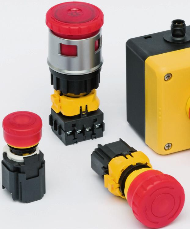
4 Emergency stop devices ES... As per EN ISO the emergency stop function is a function that is intended to avert an impending hazard for personnel, damage to the machine or work in progress, or to alleviate existing hazards, and that is to be triggered by a single user action. For this purpose controlgear is required that is equipped with a red pushbutton, that is the mushroom-head button in red; the button is to have a yellow background. The emergency stop function is generally only allowed to provide safety in addition to the directly acting safety functions. Directly acting safety functions are, for example, safety switches on safety doors that cause a hazard to be shut down without conscious action by the user. EUCHNER emergency stop controlgear features very innovative technology. All controls ES- have contact block monitoring to check whether the switching elements fitted are actually all correctly seated in the switch. If the switching elements should come loose unintentionally, an emergency stop command is triggered automatically. The controls ES-XN.. have a protective collar that makes it possible to fit a padlock when the mushroom-head button is pressed. As a result it is not possible to pull the control back out. This measure is used to provide personnel who must work in the danger area inside a machine with simple and eective protection against inadvertent power up of the machine. The reset mechanism on the EUCHNER emergency stop controlgear is very sophisticated. The majority of buttons can be reset by either turning or pulling. And this feature is not an option, but in general standard. 4
5 5
6 Emergency stop devices ES... Built-in devices 16 mm Button head red Ø 29 mm Reset by pulling or turning Short design Emergency stop device ES-XA... Head design A Dimension drawing Front panel thickness Seal Screw ring 0,8-4,5 Socket yellow Push button red 2,8 +0,2 3,2 0 3,6 15,9 20,6 Built-in devices 22 mm Button head red Ø 40 mm Contact block monitoring Reset by pulling or turning Optionally with built-in LED Emergency stop device ES-XW... Head design W Dimension drawing 32 Seal 48,7 0,5... 3,7 Front panel thickness Screw ring 37 R 0,8 max. +0,2 3, ,4 22,3 0 +0,4 24,1 0 Front panel cut-out Built-in devices 30 mm Button head red Ø 44 mm Contact block monitoring Can be locked using padlock Reset by turning Optionally with built-in LED Emergency stop device ES-XN... Head design N Dimension drawing 43 Opening for padlock Seal 61, Screw ring R 0,8 max. +0,2 4,8 0 +0,5 30,5 0 +0, , ,2 17,9 0 0,5 5,4 Front panel cut-out +0,2 16,2 0 Push button red Socket yellow Push button red Front panel thickness Front panel cut-out 6
7 Devices with housing Button head red Ø 40 mm Contact block monitoring Reset by pulling or turning Housing Optionally with built-in LED Emergency stop device ES-FB..-XW... Head design W Dimension drawing 32 Push button red Socket yellow 40 59,5,3 (2x) Bottom of housing black Top of housing yellow 15, Switching functions LED wiring diagram 2 NC Top Top 2 NC + 1 NO Top Top 4 NC Top X1 R LED LED 24V LED 24V 42 X2 Non-illuminated X X2 Non-illuminated Illuminated Non-illuminated X X2 Illuminated LED Protective diode Ordering table Series Head design Switching elements Connection Built-in LED Mushroom-head button Order No./item ES-XA (built in, 16 mm) A 2 NC Soldered connection BV without 3U02R 29 mm, red ES-XA1E-BV3U02R ES-XW (built in, 22 mm) W 2 NC + 1 NO Screw terminal 4 NC Screw terminal BV without LV with BV without LV with 412MFR 40 mm, red 412Q4MFR 40 mm, red transparent 404MFR 40 mm, red 404Q4MFR 40 mm, red transparent ES-XW1E-BV412MFR ES-XW1E-LV412Q4MFR ES-XW1E-BV404MFR ES-XW1E-LV404Q4MFR ES-FB..-XW (housing) 2 NC + 1 NO Screw terminal BV without LV with 412MFR 40 mm, red 412Q4MFR 40 mm, red transparent ES-FB1W-XW1E-BV412MFR-YO ES-FB1W-XW1E-LV412Q4MFR-YO ES-XN (built in, 30 mm) N 2 NC + 1 NO Screw terminal BL without LL with 412MFRH 44 mm, red 412Q4MFR 44 mm, red transparent ES-XN4E-BL412MFRH ES-XN4E-LL412Q4MFR Accessories for emergency stop devices ES... Ordering table Series Designation Order No./item ES-MW9Z-T1 Key for fastening the ring screw on ES-XW devices ES-MT-001 Key for fastening the ring screw on ES-XA devices ES-HWAV-27 Emergency stop label for 40 mm buttons on ES-XW devices with text Emergency Stop ES-HAAV-27 Emergency stop label for 29 mm buttons on ES-XA devices with text Emergency Stop
8 Technical data, emergency stop devices ES... Reliability values acc. to EN ISO Parameter Value Unit B10d 1 x 10 5 operating cycles Parameter Non-illuminated Value Illuminated Unit Material Mechanical life Button Housing Reinforced thermoplastic Polycarbonate 250,000 operating cycles Ambient temperature C Storage temperature C Degree of protection acc. to EN IEC ES-XA... (button) IP 65 - ES-XW... / ES-XN... (button) IP 20 - ES-FB..-XW... (housing) IP 65 Connection - ES-XA... Soldered connection - ES-XW... / ES-XN... / ES-FB..-XW... Screw terminal Contact material Silver alloy, gold flashed Positively driven According to EN Rated insulation voltage U i 250 V Utilization category acc. to EN ES-XA... DC-13 3 A 24 V - ES-XW... / ES-XN... / ES-FB..-XW... AC A 250 V (NO contacts AC A 250 V) DC-13 1 A 30 V Conventional continuous thermal current l th 1 A Switching current, min., at 24 V 10 ma Lighting data Operating voltage - 24 ± 10% V AC/DC Operating current - 15 ma 8
9 9

10 Rope pull switches In the field of safety engineering, rope pull switches belong to the category of Emergency stop devices with mechanical latching according to EN ISO The required emergency stop function must be available and functional at all times irrespective of the operating mode. After operation of the actuating element, the emergency stop device must automatically prevent or reduce the hazard in the best possible way. Type examinations To demonstrate conformity, the Machinery Directive also includes the possibility of type examination, for example. Although all relevant standards are taken into account during development, we have all our safety switches subjected to additional type examinations by a notified body. Many of the items of switchgear listed in this catalog have been tested by the German Social Accident Insurance association (DGUV), formerly the employers' liability insurance association (BG), and are given in the lists from the DGUV. Furthermore, many items of switchgear are listed by the Underwriters Laboratories (UL) and the Canadian Standards Association (CSA). These switches can be used in countries in which this listing is required. The approval symbols on the individual pages of the catalog indicate which body tested the switches. With the aid of the approval symbols listed below you can quickly see which approvals are available for the related switches: Switches with this symbol have the approval of the German Social Accident Insurance association (DGUV) formerly the employers' liability insurance association (BG). Task of rope pull switches The trip range is much larger than for switches with an emergency stop pushbutton, since operation is possible over the whole rope length and is not restricted to the small area within reach of the switch. Rope pull switches are used whenever it is necessary to protect large danger areas where it is not possible or too complex to fit a housing or cover. The advantage is that areas of an installation or machine can be shut down immediately from any point in the working area in the event of danger in cases where it would otherwise be necessary to install individual latched emergency stop buttons at short distances apart. Switches with this symbol are approved by Canadian Standards Association (CSA, Canada and USA). 10
11 Function and technology used in rope pull switches The standard EN (requirements for emergency stop pushbuttons and rope pull switches) specifies certain requirements which must be met by rope pull switches and which therefore also define the mode of operation of such switches. As such the latching device (emergency stop switch) must be reset by turning a key, by turning the pushbutton in the stated direction or by pulling. Rope pull switches are normally tripped by pulling a plastic-sheathed steel rope (known as the safety rope or pull rope). In addition, EUCHNER rope pull switches feature a latched emergency stop button on the housing which has the same eect. Upon tripping, the safety contacts are actuated and a stop signal is generated which switches o the machine. The vertical tensile force which acts on the wire or rope to generate the emergency stop signal (contact opening) must be less than 200 N and the vertical deflection of the wire or rope which is necessary for generation of the emergency stop signal must be less than 400 mm. An emergency stop signal must also be generated if the wire or rope breaks or becomes detached. This means that any fault in the safety device is noticed immediately and the safety function is not lost at any time. max. 75 m/37.5 m/25 m (246 ft/123 ft/82 ft) Installation and rope attachment Installation In accordance with EN ISO 13850: , emergency stop pushbuttons must be installed so that they can be reached easily and operated safely by persons who are at risk. It may be useful to attach marking flags to improve visibility if wires/wire ropes or ropes are used, as is the case with rope pull switches. A tensioner spring must be installed on the thrust bearing in order to ensure proper and safety-compliant implementation of the pull rope system. This is a precondition for direction-independent tripping at any point along the rope length. Rope attachment Versions RPS...SC and RPS...PC Strip the pull rope and insert into the clamping head. In order to prevent the pull rope from slipping, there must be no rope coating in the clamping head. Set the pull rope so that the lock marking is in central position and clamp the pull rope with the hexagon socket head screw. Actuate the pull rope hard several times in order to stretch the rope and then reset the rope using the clamping head. Set the lock marking in central position by turning the actuation axis. Activate the rope pull switch by turning the Reset knob in the direction of the arrow (RPS...SC) or by pulling (RPS...PC). In order to achieve this, the rope pull switch has one center position and two switch-o positions. The switch is in center position during machine operation. If the safety rope is pulled or breaks, the switch moves from the center position to one of the switch-o positions and the machine is stopped. Rope pull switches from EUCHNER have a window which allows the switch position to be seen. The direction of the safety rope can be changed using rope pulley blocks or eyebolts. Direction changes of up to max. 90 are possible. Rope pulley blocks have the advantage that the frictional forces between the safety rope and deflection points are kept low. State on delivery and position in the event of a rope break/tear Correct rope tension, switch active/can be activated Position on loading/tripping of pre-tensioned rope 11
12 Temperature dependence When planning safety installations with rope pull switches, it is necessary to take into account the temperature dependence of the installation and the safety rope so that the switch is not tripped as a result of a change in temperature. To do this, the possible rope lengths must be determined and the trip point must be readjusted regularly. The following graph shows the relationship between rope length and temperature. Installation should take place at a temperature of 20 C. Empfohlene Seillänge in Abhängigkeit von der Umgebungstemperatur 70 Seillänge [m] RPS einseitig und ohne Gegenfeder abgespannt RPS Seillänge [m] RPS Temperaturbereich [ C] RPS


13 Selection table for rope pull switches RPS Housing material K M Plastic Metal Version P S Blue reset button Emergency stop Rope attachment R C Pull lug Clamping head Actuating force 100 Actuating force 100 N 175 Actuating force 175 N 300 Actuating force 300 N LED LED left or right Switching element Four 3 NC + 1 NO or contacts Connection M BHA Thread M20 x 1.5 for cable gland Plug connector 10-pin Switching Housing material Version Rope attachment Actuating force [N] Connection element, LED Page 4 contacts Plastic Metal P S R C M MR

14 Rope pull switch with pull- or turn-to-reset button for emergency stop device Plastic housing Emergency stop device with detent mechanism according to EN ISO and EN Pull lug or clamping head for pull rope Indication of correct rope tension 3 cable entries M20 x 1.5 Switching elements with 4 contacts Cable entry M20 x 1.5 Pull-to-reset button for emergency stop, pull lug for tensioning rope Dimension drawing Pull lug Window Pull-to-reset button (blue button) ,3 33, x1,5 19,5 224 Switching elements f Slow-action switching contact 3 NC + 1 NO f Slow-action switching contact 30 42, , ,3 Cable glands, see page 20 Wiring diagrams Switch not activated For switching functions see technical data on Page 22 Ordering table Series Connection Rope attachment Version RPS Cable entry 3 x M20 x 1.5 R Pull lug P Blue reset button Actuating force [N] Switching element 3 NC + 1 NO 3 NC + 1 NO 3 NC + 1 NO Order No./item RPSPR100M RPSPR100M RPSPR175M RPSPR175M RPSPR300M RPSPR300M 14
15 Cable entry M20 x 1.5 Pull-to-reset button for emergency stop, clamping head for tensioning rope Cable entry M20 x 1.5 Turn-to-reset button for emergency stop, clamping head for tensioning rope Dimension drawing Clamping head Clamping head (adjustable via S) 5 5,3 5 5, ,4 20x1,5 19, ,5 20x1,5 S = S = Window Pull-to-reset button (blue button) (adjustable via S) Window 48 Emergency stop with turn-to-reset button (red button) 30 42, , ,3 88 Cable glands, see page 20 Cable glands, see page , ,5 45 Wiring diagrams Switch not activated For switching functions see technical data on Page 22 For switching functions see technical data on Page 22 Ordering table Series Connection Rope attachment Version RPS Cable entry 3 x M20 x 1.5 C Clamping head P Blue reset button S Emergency stop Actuating force [N] Switching element 3 NC + 1 NO 3 NC + 1 NO 3 NC + 1 NO 3 NC + 1 NO 3 NC + 1 NO 3 NC + 1 NO Order No./item RPSPC100M RPSPC100M RPSPC175M RPSPC175M RPSPC300M RPSPC300M RPSSC100M RPSSC100M RPSSC175M RPSSC175M RPSSC300M RPSSC300M 15
16 Rope pull switch with turn-to-reset button for emergency stop device Plastic housing Emergency stop device with detent mechanism according to EN ISO and EN Clamping head for pull rope Indication of correct rope tension Plug connector MR10 LED left or right Switching element with 4 switching contacts Plug connector MR10 10-pin, turn-to-reset button for emergency stop, clamping head for tensioning rope Dimension drawing LED on the right is a mirror image S = , Clamping head (adjustable via S) Window Emergency stop with turn-to-reset button (red button) Switching elements f Slow-action switching contact ,5 Ø 48 5,3 Ø ,5 For plug connectors see page 20 Wiring diagrams Switch not activated MR RD For switching functions see technical data on Page 22 Ordering table Series Connection Rope attachment Version RPS Plug connector MR10 C Clamping head S Emergency stop Actuating force [N] Switching element LED Left Right Left Right Left Right Order No./item RPSSC100BHA10LL RPSSC100BHA10RL RPSSC175BHA10LL RPSSC175BHA10RL RPSSC300BHA10LL RPSSC300BHA10RL024 16
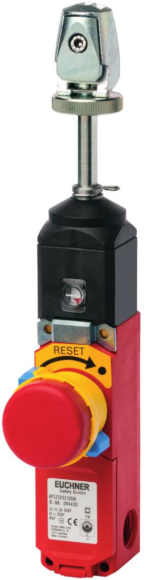
17 Rope pull switch with pull-to-reset button for emergency stop device Metal housing Emergency stop device with detent mechanism according to EN ISO and EN Clamping head for pull rope Indication of correct rope tension 3 cable entries M20 x 1.5 Switching elements with 4 contacts Pre-failure monitoring for the rope tension optional Pre-failure monitoring An additional monitoring output is used to signal that the permissible rope tension is exceeded and to indicate imminent triggering. Switching elements f Slow-action switching contact Cable entry M20 x 1.5 Pull-to-reset button for emergency stop, clamping head for tensioning rope Dimension drawing max.=282 / min.= ,5 8 Wiring diagrams Switch not activated ,5 78 5,4 M20x1,5 26 S=45 20,5 30,5 20,5 30,5 53 SW17 Clamping head 88 Emergency stop with pull-to-reset button (red button) Window Cable glands, see page 20 S2 S Pre-failure monitoring For switching functions see technical data on Page 22 Ordering table Series RPS-M Connection Cable entry 3 x M20 x 1.5 Rope attachment C Clamping head Version S Emergency stop Actuating force [N] Switching element Pre-failure monitoring with without with without Order No./item RPS-M-E-SC175M RPS-M-SC175M RPS-M-E-SC300M RPS-M-SC300M 17
18 Accessories for rope pull switches Eyebolt Rope set Pulley set Rope pulley block Turnbuckle Tensioner spring Tensioning rope Built-in LED Eyebolt Thread M8 Dimension drawings Rope set 28, Thimble Built-in LED The built-in LED is suitable for direct installation in one of the M20 x 1.5 threads of the three cable entries in the rope pull switch RPS. The built-in LED indicates to the operator whether the switch is actuated or not. The switching element can be wired individually. Operating voltage DC 24 V +10%, -15% ~ Rope clamp Pulley set RPS-PS/V5 Rope pulley block RPS-P/V1 Turnbuckle Left-handed thread 58 Ø 9 M Ø 14 M6 RPS-B-6-60 = 60 RPS-B = Rope pulley block Pulley bracket 19 Ordering table Designation Version Packaging unit Order No./item Eyebolt Thread M8 5 ea. Rope set Consisting of thimble and rope clamp 5 ea. Pulley set RPS-PS/V5 Rope pulley block RPS-P/V1 Turnbuckle Consisting of rope pulley block 9 mm and pulley bracket Rope pulley block 14 mm M6 x 60 M6 x ea. 1 ea. 5 ea. 1 ea RPS-O-8-50/V RPS-RS/V RPS-PS/V RPS-P/V RPS-B-6-60/V RPS-B
19 1 8 Emergency Stop Devices/Rope Pull Switches Tensioner spring RPS-W-100/175: L0 min. = 383 RPS-W-300: L0 min. = min. Tensioning rope Built-in LED 28,7 38,5 26,5 R11,8 ca ,5 9,5 M20x1, RPS-W-100/175: L max. = 487 RPS-W-300: L max. = 653 F Plastic sheath, red SW27 Ordering table Designation Version Packaging unit Order No./item Tensioner spring Tensioning rope Built-in LED For tensile force 110 N / 175 N For tensile force 300 N Length 50 m Length 100 m Color red for cable entry M20 x 1.5, with seal Light radiation to side Color red for cable entry M20 x 1.5, with seal light radiation to front 1 ea. 1 ea. 1 ea. 1 ea. 1 ea. 1 ea RPS-W-100/ RPS-W RPS-I-3-4/50m RPS-I-3-4/100m LED M20x LED-F M20x1.5 19
20 Female connectors/extension cables for rope pull switch RPS...MR10 Female connector with cable 10-pin Dimension drawings 64 Ø 9, Ø View on connection side, socket Female connector Cable length L Extension cable 10-pin Ø 9, Ø Cable length L View on connection side, socket Female connector Coupling plug Assignment of female connector MR10 with cable Pin Wire color Conductor cross-section 1 OG 0.82 (18 AWG) 2 BU 0.82 (18 AWG) 3 WH/BK 0.82 (18 AWG) 4 RD/BK 0.82 (18 AWG) 5 GN/BK 0.82 (18 AWG) Pin Wire color Conductor cross-section 6 OG/BK 0.82 (18 AWG) 7 RD 0.82 (18 AWG) 8 GN/YE 0.82 (18 AWG) 9 BK 0.82 (18 AWG) 10 WH 0.82 (18 AWG) Ordering table Version Material Cable length L [mm] 1,800 3,600 6,000 9,100 12,100 15,200 18,200 Female connector with cable Extension cable PVC PUR PVC PUR Cable glands M20 x 1.5 A B Cable glands Suitable for various cable diameters. Versions available in plastic and metal. Article Thread Cable [mm] A [mm] B [mm] E [mm] SW [mm] E M EKP.20/06 M20 x EKV.20/06 M20 x EKV.20/09 M20 x SW Ordering table Thread Version Cable diameter 6-12 mm Metal - Material Plastic EKPM20/06 M20 x 1.5 Cable diameter mm EKVM20/06 - Cable diameter 9-13 mm EKVM20/09-20


21 Technical data, rope pull switch RPS The technical data on switches and switching elements apply to all connections. Further technical data are given for the connection selected. Reliability values acc. to EN ISO Parameter Value Unit B10d RPS 2 x 10 4 operating cycles RPS-M 2 x 10 5 operating cycles Switch, plastic housing Parameter Value Unit Housing material Reinforced thermoplastic Actuation material Die-cast zinc, steel Mechanical life Acc. to IEC Ambient temperature C Weight Approx kg Latching device Acc. to EN ISO RPS RPS RPS Actuating force N Rope length max m Rope diameter mm Rope attachment RPS...R... Via pull lug RPS...C... Via clamping head Version RPS...P... Blue reset button RPS...S... Emergency stop Switch, metal housing Parameter Value Unit Housing material Die-cast aluminum Actuation material Die-cast zinc, steel Mechanical life Acc. to IEC Ambient temperature C Weight Approx kg Latching device Acc. to EN ISO RPS RPS Actuating force N Rope length max m Rope diameter mm Rope attachment RPS...C... Via clamping head Version RPS...S... Emergency stop Switching element 4 Parameter Switching principle Switching element with 4 switching contacts 3 NC + 1 NO Value Slow-action switching contact Contact opening gap > 2 x 2 mm Min. switching current at 24 V DC 10 ma Pre-failure monitoring Parameter Value Unit Rated insulation voltage Ui 250 V AC/DC Conventional thermal current Ith 10 A Rated operating voltage U e 240 V Utilization category according to IEC AC-15 Ie 3 A Ue 240 V / Ie 6 A Ue 120 V DC-13 Ie 0.27 A Ue 250 V DC-15 Ie 0.55 A Ue 125 V Short circuit protection acc. to IEC (control circuit fuse) 6 A DII/gG Safety class I Unit
22 Connection, cable entry M20 x 1.5 M20x1,5 Parameter Connection Screw terminal Version M20 x 1.5 Conductor cross-section mm² Degree of protection according to IEC IP 67 Rated insulation voltage Ui 250 V AC/DC Rated impulse withstand voltage Uimp 2.5 kv Conventional thermal current Ith 10 A Short circuit protection acc. to IEC (control circuit fuse) 6 A DII/gG Utilization category according to IEC AC-15 Ie 3 A Ue 240 V Value Unit Connection, plug connector MR10 10-pol Parameter Value Unit Connection Plug connector Version MR10 (10-pin) Degree of protection according to IEC IP 65 1) Rated insulation voltage Ui 50 V AC/DC Rated impulse withstand voltage Uimp 2.5 kv Conventional thermal current Ith 4 A Short circuit protection acc. to IEC (control circuit fuse) 4 A gg Utilization category according to IEC AC-15 Ie 3 A Ue 50 V DC-13 Ie 3 A Ue 24 V 1) Screwed tight with the related plug connector (see page 20) Travel diagram RPS... Travel diagram RPS... ON OFF Tensile force N ±15% 300N/175N/100N Detent mechanism ON OFF Tensile force N ±15% 300N/175N/100N Detent mechanism 240N/140N/80N 240N/140N/80N Detent mechanism 180N/105N/60N Detent mechanism 180N/105N/60N Travel diagram RPS-M-... with metal housing Travel diagram RPS-M-E-... with metal housing and pre-failure monitoring ON OFF S1 S2 Pre-failure monitoring +6mm +4,8mm +4mm +3mm Tensile force N ±15% 300N / 175N Detent mechanism 0mm 288N / 133N -3mm -4mm -4,8mm -6mm Detent mechanism 156N / 91N 22
23 Technical data, rope pull switch RPS accessories Tensioner spring Parameter Value Unit Material of rope clamp Die-cast zinc/steel Material of spring X12CrNi177 (1.4310) Eyebolt DIN 444 M12x Zn Ambient temperature C Rope diameter mm Rope attachment Quick-action clamping device RPS-W-100/175 RPS-W-300 Spring rate N/mm Maximum spring force N Weight Approx. 0.5 Approx kg Built-in LED Parameter Value Unit Material of housing ABS/PC blend, black Material of cap Transparent polycarbonate Degree of protection (fitted in rope pull switch) IP 65 Ambient temperature C Connection 2 strands Mounting M20 x 1.5 Operating voltage 24 V DC Switch-on current < 0.5 A Current consumption 45 ma 23
24 Item Index Index by item designation Item Order no. Page Item Order no. Page EKPM20/ RPSPR300M EKVM20/ RPSSC100BHA10LL EKVM20/ RPSSC100BHA10RL ES-FB1W-XW1E-BV412MFR-YO RPSSC100M ES-FB1W-XW1E-LV412Q4MFR-YO RPSSC175BHA10LL ES-HAAV RPSSC175BHA10RL ES-HWAV RPSSC175M ES-MT RPSSC300BHA10LL ES-MW9Z-T RPSSC300BHA10RL ES-XA1E-BV3U02R RPSSC300M ES-XN4E-BL412MFRH ES-XN4E-LL412Q4MFR ES-XW1E-BV404MFR ES-XW1E-BV412MFR ES-XW1E-LV404Q4MFR ES-XW1E-LV412Q4MFR Female connector with PUR cable, 1.8 m Female connector with PUR cable, 12.1 m Female connector with PUR cable, 15.2 m Female connector with PUR cable, 18.2 m Female connector with PUR cable, 3.6 m Female connector with PUR cable, 6.0 m Female connector with PUR cable, 9.1 m Female connector with PVC cable, 1.8 m Female connector with PVC cable, 12.1 m Female connector with PVC cable, 15.2 m Female connector with PVC cable, 3.6 m Female connector with PVC cable, 6.0 m Female connector with PVC cable, 9.1 m LED M20x LED-F M20x PUR extension cable, 15.2 m PUR extension cable, 6.0 m PVC extension cable, 3.6 m PVC extension cable, 9.1 m RPS-B RPS-B-6-60/V RPS-I-3-4/100m RPS-I-3-4/50m RPS-M-SC175M RPS-M-SC300M RPS-M-E-SC175M RPS-M-E-SC300M RPS-O-8-50/V RPS-P/V RPS-PS/V RPS-RS/V RPS-W-100/ RPS-W RPSPC100M RPSPC175M RPSPC300M RPSPR100M RPSPR175M RPSPR300M RPSSC100M RPSSC175M RPSSC300M RPSPC100M RPSPC175M RPSPC300M RPSPR100M RPSPR175M
25 Item Index Index by order number Order no. Item Page Order no. Item Page EKVM20/ ES-MT EKVM20/ ES-HWAV EKPM20/ ES-HAAV LED M20x1, ES-XA1E-BV3U02R RPSSC100M ES-XW1E-BV404MFR RPSSC175M ES-XW1E-LV404Q4MFR RPSSC300M RPS-M-E-SC175M RPSPC100M RPS-M-E-SC300M RPSPC175M RPS-M-SC175M RPSPC300M RPS-M-SC300M RPSPR100M RPSPR175M RPSPR300M RPS-W-100/ RPS-W RPS-O-8-50/V RPS-RS/V RPS-B-6-60/V RPS-B RPS-PS/V RPS-I-3-4/50m RPS-I-3-4/100m RPSSC100BHA10LL RPSSC100BHA10RL RPSSC175BHA10LL RPSSC175BHA10RL RPSSC300BHA10LL RPSSC300BHA10RL RPSSC100M RPSSC175M RPSSC300M RPSPR100M RPSPR175M RPSPR300M RPSPC100M RPSPC175M RPSPC300M LED-F M20x1, RPS-P/V Female connector with PVC cable, 1.8 m Female connector with PVC cable, 3.6 m Female connector with PVC cable, 6.0 m Female connector with PVC cable, 9.1 m Female connector with PVC cable, 15.2 m PVC extension cable, 3.6 m PVC extension cable, 9.1 m Female connector with PUR cable, 9.1 m PUR extension cable, 6.0 m PUR extension cable, 15.2 m Female connector with PVC cable, 12.1 m Female connector with PUR cable, 1.8 m Female connector with PUR cable, 3.6 m Female connector with PUR cable, 6.0 m Female connector with PUR cable, 12.1 m Female connector with PUR cable, 15.2 m Female connector with PUR cable, 18.2 m ES-XW1E-BV412MFR ES-XW1E-LV412Q4MFR ES-XN4E-BL412MFRH ES-XN4E-LL412Q4MFR ES-FB1W-XW1E-BV412MFR-YO ES-FB1W-XW1E-LV412Q4MFR-YO ES-MW9Z-T1 7 25
26 Representatives International Australia Micromax Sensors & Automation Unit 2, Beaconsfield Street Silverwater, NSW 28 Tel Fax info@micromaxsa.com.au Austria EUCHNER GmbH Süddruckgasse Tribuswinkel Tel Fax info@euchner.at Benelux EUCHNER (BENELUX) BV Visschersbuurt AE Papendrecht Tel Fax info@euchner.nl Brazil EUCHNER Ltda Av. Prof. Luiz Ignácio Anhaia Mello, no S. Lucas São Paulo - SP - Brasil CEP Tel Fax euchner@euchner.com.br Canada IAC & Associates Inc. 80 Fasan Drive Unit A Oldcastle, Ontario N0R 1L0 Tel Fax sales@iacnassociates.com China EUCHNER (Shanghai) Trading Co., Ltd. No. 8 Workshop A, Hi-Tech Zone 503 Meinengda Road Songjiang Shanghai Tel Fax info@euchner.com.cn Czech Republic EUCHNER electric s.r.o. Videňská 134/ Brno Tel Fax info@euchner.cz Denmark Duelco A/S Systemvej Aalborg SV Tel Fax info@duelco.dk Finland Sähkölehto Oy Holkkitie Helsinki Tel Fax oice@sahkolehto.fi France EUCHNER France S.A.R.L. Parc d Aaires des Bellevues Allée Rosa Luxembourg Bâtiment le Colorado ERAGNY sur OISE Tel Fax info@euchner.fr Hong Kong Imperial Engineers & Equipment Co. Ltd. Unit B 12/F Cheung Lee Industrial Building 9 Cheung Lee Street Chai Wan Hong Kong Tel Fax info@imperial-elec.com Hungary EUCHNER Ges.mbH Magyarországi Fióktelep 2045 Törökbálint FSD Park 2. Tel Fax info@euchner.hu India EUCHNER (India) Pvt. Ltd. 401, Bremen Business Center, City Survey No. 2562, University Road Aundh, Pune Tel Fax info@euchner.in Israel Ilan & Gavish Automation Service Ltd. 26 Shenkar St. Qiryat Arie P.O. Box Petach Tikva Tel Fax mail@ilan-gavish.com Italy TRITECNICA S.r.l. Viale Lazio Milano Tel Fax info@tritecnica.it Japan EUCHNER Representative Oice Japan Kamitsurumahoncho Minami-ku, Sagamihara-shi Kanagawa Tel Fax hayashi@euchner.jp Solton Co. Ltd , Shin-Yokohama Kohoku-ku, Yokohama Japan Tel Fax sales@solton.co.jp Korea EUCHNER Korea Co., Ltd. RM 810 Daerung Technotown 3rd #448 Gasang-Dong Gumcheon-gu, Seoul Tel Fax info@euchner.co.kr Mexico SEPIA S.A. de C.V. Maricopa # , Col. Napoles. Del. Benito Juarez Mexico D.F. Tel Fax alazcano@sepia.mx Poland ELTRON Pl. Wolności 7B Wrocław Tel Fax eltron@eltron.pl Republic of South Africa RUBICON ELECTRICAL DISTRIBUTORS 4 Reith Street, Sidwell 6061 Port Elizabeth Tel Fax sales@rubiconelectrical.com Romania First Electric SRL Str. Ritmului Nr. 1 Bis Ap. 2, Sector Bucuresti Tel Fax oice@firstelectric.ro Singapore Sentronics Automation & Marketing Pte Ltd. Blk 3, Ang Mo Kio Industrial Park 2A #05-06 Singapore Tel Fax sentronics@pacific.net.sg Slovakia EUCHNER electric s.r.o. Videňská 134/ Brno Tel Fax info@euchner.cz Slovenia SMM proizvodni sistemi d.o.o. Jaskova Maribor Tel Fax franc.kit@smm.si Spain EUCHNER, S.L. Gurutzegi 12 - Local 1 Polígono Belartza San Sebastian Tel Fax comercial@euchner.es Sweden Censit AB Box Värnamo Tel Fax info@censit.se Switzerland EUCHNER AG Grofstrasse Mels Tel Fax info@euchner.ch Taiwan Daybreak Int l (Taiwan) Corp. 3F, No. 124, Chung-Cheng Road Shihlin 11145, Taipei Tel Fax day111@ms23.hinet.net Turkey EUCHNER Endüstriyel Emniyet Teknolojileri Ltd. Şti. Hattat Bahattin Sok. Ceylan Apt. No. 13/A Göztepe Mah Kadıköy / Istanbul Tel Fax info@euchner.com.tr United Kingdom EUCHNER (UK) Ltd. Unit 2 Petre Drive, Sheield South Yorkshire S4 7PZ Tel Fax info@euchner.co.uk USA EUCHNER USA Inc Lyons Street East Syracuse, NY Tel Fax info@euchner-usa.com EUCHNER USA Inc. Detroit Oice 130 Hampton Circle Rochester Hills, MI Tel Fax info@euchner-usa.com Germany Chemnitz EUCHNER GmbH + Co. KG Ingenieur- und Vertriebsbüro Am Vogelherd Bobritzsch Tel Fax jens.zehrtner@euchner.de Düsseldorf EUCHNER GmbH + Co. KG Ingenieur- und Vertriebsbüro Sundernholz Essen Tel Fax juergen.eumann@euchner.de Essen/Dortmund Thomas Kreißl fördern - steuern - regeln Hackenberghang 8a Essen Tel Fax info@kreissl-essen.de Wiesbaden EUCHNER GmbH + Co. KG Ingenieur- und Vertriebsbüro Schiersteiner Straße Wiesbaden Tel Fax giancarlo.pasquesi@euchner.de Freiburg EUCHNER GmbH + Co. KG Ingenieur- und Vertriebsbüro Steige Breisach Tel Fax peter.seifert@euchner.de Hamburg EUCHNER GmbH + Co. KG Ingenieur- und Vertriebsbüro Bleickenallee Hamburg Tel Fax volker.behrens@euchner.de Magdeburg EUCHNER GmbH + Co. KG Ingenieur- und Vertriebsbüro Tismartraße Magdeburg Tel Fax bernhard.scholz@euchner.de München EUCHNER GmbH + Co. KG Ingenieur- und Vertriebsbüro Obere Bahnhofstraße Germering Tel Fax st.kornes@euchner.de Nürnberg EUCHNER GmbH + Co. KG Ingenieur- und Vertriebsbüro Steiner Straße 22a Oberasbach Tel Fax ralf.paulus@euchner.de Stuttgart EUCHNER GmbH + Co. KG Ingenieur- und Vertriebsbüro Kohlhammerstraße Leinfelden-Echterdingen Tel Fax oliver.laier@euchner.de uwe.kupka@euchner.de 06/13 26


27 Support hotline You have technical questions about our products or how they can be used? For further questions please contact your local sales representative. Comprehensive download area You are looking for more information about our products? You can simply and quickly download operating instructions, CAD or eplan data and accompanying software for our products at Customer-specifi c solutions You need a specifi c solution or have a special requirement? Please contact us. We can manufacture your custom product even in small quantities. EUCHNER near you You are looking for a contact at your location? Along with the headquarters in Leinfelden-Echterdingen, the worldwide sales network includes 15 subsidiaries and numerous representatives in Germany and abroad you will defi nitely also fi nd us near you. 27

28 EN EUCHNER GmbH + Co. KG Kohlhammerstraße Leinfelden-Echterdingen Germany Tel Fax info@euchner.de /13 Subject to technical modifi cations, no responsibility is accepted for the accuracy of this information. EUCHNER GmbH + Co. KG TA
Emergency Stop Devices/Rope Pull Switches
 Rope pull switch with pulltoreset button for emergency stop device Metal housing Emergency stop device with detent mechanism according to EN ISO 13850 and EN 602041 Clamping head for pull rope Indication
Operating Instructions Rope Pull Switches RPS...
 Safety rope pull switch RPS Correct use In accordance with EN 60947-5-5, EN ISO 13850, it must be ensured that parts of or complete industrial machines or installations can be stopped as quickly as possible
Operating instructions Safety Rope Emergency Stop Switches ZB0052 / ZB0053 ZB0072 / ZB0073
 Operating instructions Safety Rope Emergency Stop Switches UK ZB0052 / ZB0053 ZB0072 / ZB0073 7390878 / 02 03 / 2011 Contents 1 Safety instructions...3 2 Installation / set-up...4 2.1 Applications...4
Safety Rope Pull Switches SR and SRM
 Safety Rope Pull Switches SR and SRM Safety Rope Pull Switches For more safety on the production line Whether on the conveyor belt or on the machine when maximum safety is required, BERNSTEIN rope pull
Position switches FP series
 A Position switches FP series Selection diagram 0 08 8 9 0 0 0 Ø 8 mm Ø, mm external rubber stainless steel stainless steel fiber glass rod gasket sphere sphere adjustable lever safety adjustable lever
ERS200. Safety Command Devices. Original Phone: operating instructions - Fax: Web:
 ERS200 Safety Command Devices EN 2011/07-607330 We reserve the right to make technical changes Original Phone: operating 800.894.0412 instructions - Fax: 888.723.4773 - Web: www.clrwtr.com - Email: info@clrwtr.com
Prewired position switches FA series
 Prewired position switches Technical data Housing Made of metal, coated with baked epoxy powder 2 m wired cable with 5x0,5 mm 2 wires marked SEV and IMQ Protection degree: IP6 General data Ambient temperature:
Prewired position switches FA series
 2 Prewired position switches FA series Selection diagram 01 08 10 11 1 15 1 02 external rubber gasket external rubber gasket 1 51 52 54 55 56 5 ACTUATORS adjustable lever safety adjustable lever 41 45
TeSys protection components
 Presentation, description -pole thermal overload relays TeSys D Presentation TeSys D thermal overload relays are designed to protect a.c. circuits and motors against: b overloads, b phase failure, b excessively
Zelio Relays RSL Slim Interface Plug-In Relays
 Zelio Relays RSL Slim Interface Plug-In Relays Catalog 8501CT0901 2009 Class 8501 CONTENTS Description............................................. Page Introduction.................................................3
F series Foot Switches
 F series Foot Switches ITC presents a complete line of foot switches from Bernstein, designed to respond to the most stringent requirements for machine control and safety applications. The F series includes
TERMINAL BLOCK SUMMARY
 TERMINAL BLOCK SUMMARY TERMINAL BLOCK SUMMARY TERMINAL BLOCK SUMMARY FEEDTHROUGH TERMINALS FUSE TERMINALS DISCONNECT TERMINALS MICRO TERMINALS CIRCUIT BREAKERS PRODUCT INFORMATION Feedthrough Terminals
Water Flow Regulators. The Leading Water Flow Regulator Worldwide. Essential Equipment For every injection and blow molding machine
 The Leading Water Flow Regulator Worldwide Essential Equipment For every injection and blow molding machine Why You Should Use Wittmann Water Flow Regulators: Instant indication of blocked mold cooling
Hand lever valves VHER
 Hand lever valves VHER Hand lever valves VHER Key features Powerful Flexible Practical -M- Flow 170 3800 l/min 4/3-way valve mid-position closed mid-position exhausted mid-position pressurised Connections:
Electromechanical pressure switches
 References : pages / and / page /5 Presentation Functions Pressure switches type XMX and XMA are switches for control circuits, with an adjustable differential. They are used to control the pressure of
Electromechanical pressure switches
 Presentation Electromechanical pressure switches OsiSense XM For power circuits, type XMP Presentation Pressure switches type XMP are switches for power circuits (direct switching), with an adjustable
Actuating elements for ComEx
 Description A large number of variants and versions of actuating elements are available for the ComEx control and indicator units. All actuating elements are made of high-quality thermoplastic and conform
ASB Accumulator Safety Blocks
 ASB Accumulator Safety Blocks For working pressures up to 350 bar Catalogue HY07-1241/UK Note: In line with our policy of continuing product improvement, specifications in this catalogue are subject to
XMPA12B2142 pressure sensor XMP - 12 bar - G 1/4 female - 2 NC - without control type
 Characteristics pressure sensor XMP - 12 bar - G 1/4 female - 2 NC - without control type Main Range of product Pressure sensor type Pressure sensor name Pressure sensor size OsiSense XM Electromechanical
SCH-27. Diaphragm Pressure Switch. Setting range: mbar to bar. Temperature: max C. Material: stainless steel
 Diaphragm Pressure Switch measuring monitoring analysing SCH-27 P3 Setting range: 0.7... 6 mbar to 8... 160 bar Temperature: max. +100 C Material: stainless steel Connection: G ½ male, ½" NPT male, ¼"
Remote Control VP04 Pneumatic Proportional Remote Control Valve zrc02. Catalogue HY /UK December, 2004
 Remote Control Pneumatic Proportional Remote Control Valve zrc02 Catalogue HY17-8356/UK December, 2004 Catalogue Information Catalogue layout This catalogue has been designed to give a brief overview of
For Air Pressure. AP-30 Series. Digital Display & Digital Control. EASY-TO-SEE 2-color display. Two-color digital display pressure sensor
 Cat No AP3-KA-C Two-color digital display pressure sensor AP-3 Series Digital Display & Digital Control For Air Pressure EASY-TO-SEE 2-color display Green and red two-color LED display clearly shows abnormal
HydroCOM: High energy savings and excellent controllability
 HydroCOM: High energy savings and excellent controllability Almost all applications require efficient capacity control systems Most of them simply waste energy, are slow and inaccurate. HydroCOM, however,
1 Overview. Pressure Measurement Transmitters for basic requirements. 1/16 Siemens FI SITRANS P220 for gauge pressure
 Siemens AG 204 Overview The pressure transmitter SITRANS P220 measures the gauge pressure of liquids, gases and vapors. Stainless steel measuring cell, fully welded Measuring ranges 2.5 to 600 bar (36.3
References 6 k thermal overload relays, adjustable from 0.11 to 16 A
 s 6 k thermal overload relays, adjustable from 0.11 to 16 A 3-pole relays with screw clamp terminals These overload relays are designed for the protection of motors. They are compensated and phase failure
Compact pressure switches for gas and air
 Compact pressure es for gas and air / 5.0 Printed in Germany Edition 0.8 Nr. 9 544 6 Technical description The pressure is an adjustable compact pressure according to EN 854 for combustion plants. The
Gas density monitor With integrated transmitter Model GDM-100-TI
 SF 6 gas solutions Gas density monitor With integrated transmitter Model GDM-100-TI grid Products WIKA data sheet SP 60.05 for further approvals see page 5 Applications Gas density monitoring of closed
CFSW. Hinges with built-in safety multiple switch
 CFSW. Hinges with built-in safety multiple switch ELESA Original design Elesa Standards Main dimensions Fitting Weight Code Description L B f ±0.2 f 1 ±0.2 H h 1 h 2 d 3 d 4 C [Nm]# g 426601 CFSW.110-6-2NO+2NC-C-A
LMP 307. Stainless Steel Probe. Stainless Steel Sensor. accuracy according to IEC 60770: standard: 0.35 % FSO option: 0.25 % / 0.
 LMP 07 Stainless Steel Sensor accuracy according to IEC 60770: standard: 0.5 % FSO option: 0.5 % / 0. % FSO Nominal pressure from 0... mho up to 0... 50 mho Output signals -wire: 4... 0 ma -wire: 0...
High-performance submersible pressure transmitter For level measurement Model LH-10
 Electronic pressure measurement High-performance submersible pressure transmitter For level measurement Model LH-10 WIKA data sheet PE 81.09 Applications Level measurement in rivers and lakes Deep well
KMT. Thermal Mass Flow Meter. for Compressed Air and Gases. Measuring range: m3n/h m3 N
 Thermal Mass Flow Meter for Compressed Air and Gases measuring monitoring analysing KMT Measuring range: 0.32... 63 m3n/h... 3.5... 1400 m3 N /h Accuracy: ±2,5% of reading + 0,15% of full scale p max :
Meta-MEC Manual Motor Starters
 Leader in Electrics & Automation Meta-MEC Manual Motor Starters Electric Equipment LG Meta-MEC Manual Motor Starters provide completed ranges up to 100A 45 mm 55 mm 32AF 2 45 mm 70 mm 63AF 100AF 3 LG Meta-MEC
UPB All fluids. Full flow All stainless steel
 UPB All fluids Full flow All stainless steel High-quality, efficient... Applications Quick connections for the following circuits: - draining, - filling, - fluid transfer, - etc. Fluids Wide range of fluids,
PFH. Application example. Pneumatic 2-Finger Parallel Gripper Long-stroke Gripper. Weight 2.65 kg 12.6 kg. Gripping force 630 N 2950 N
 PFH www.comoso.com Sizes 30 50 Weight 2.65 kg 12.6 kg Gripping force 630 N 2950 N Stroke per finger 30 mm 100 mm Workpiece weight 3.15 kg 13 kg Application example Assembly unit for intermediate sleeves
Safety. Operating instructions Solenoid valve for gas VG 6 VG 15/10 DANGER. Contents WARNING CAUTION. Changes to edition 09.14
 15 Elster GmbH Edition 7.15 Translation from the German 519 D F NL I E DK S N P GR TR CZ PL RUS H www.docuthek.com Operating instructions Solenoid valve for gas VG VG 15/1 Contents Solenoid valve for gas
Tightness controls TC 1 3 and TC 4
 Tightness controls TC 1 3 and TC 4 Test of both safety valves Short test period thanks to logical decision-making in the program sequence Adjustable test period which can be adapted to different systems
Differential Pressure Control Types MP 54, MP 55 and MP 55A
 MAKING MODERN LIVING POSSIBLE Data sheet Differential Pressure Control Types MP 54, MP 55 and MP 55A MP 54 and MP 55 oil differential pressure controls are used as safety switches to protect refrigeration
Auxiliary Valve PRS6 Pressure Reducing Valve. Catalogue HY /UK June 2003
 Auxiliary Valve Pressure Reducing Valve June 2003 General Subject to alteration without prior notice. The curves and diagrams in this catalogue are typical examples only. While the contents of the catalogue
Proportional pressure regulators VPPE
 Proportional pressure regulators VPPE Proportional pressure regulators VPPE Product range overview Function Version Pneumatic connection Proportional pressure regulator Nominal size for pressurisation/
Pneumatic spool valve islands
 Pneumatic spool valve islands P7.GB.R MEGA SPOOL VALVE ISLANDS MEGA pneumatic spool valve islands offer maximum performance along with flexibility, easy installation and simple operation. Due to their
e.do Gripper Safety requirements, technical features and assembly and integration instructions
 e.do Gripper Safety requirements, technical features and assembly and integration instructions Requirements, technical features and instructions for safe installation and use of the e.do Gripper. CR00758190-en_00/2018.05
Differential pressure controls, Type MP 54, 55 and 55A
 MAKING MODERN LIVING POSSIBLE Technical brochure Differential pressure controls, Type MP 54, 55 and 55A MP 54 and oil pressure controls are used as safety switches to protect refrigeration compressors
Differential pressure switch MP 54, MP 55 and MP 55A
 Data sheet Differential pressure switch MP 54, MP 55 and MP 55A MP 54 and MP 55 oil differential pressure switches are used as safety switches to protect refrigeration compressors against low lubricating
SG33KTL-M Quick Installation Guide. 1 Unpacking and Inspection
 SG33KTL-M Quick Installation Guide This guide provides a general instruction of the installation procedures of SG33KTL-M. In no case shall this guide substitute for the user manual or related notes on
Limit switches OsiSense XC Special For material handling applications, type XC1 AC
 Presentation For material handling applications, type XC C b XC C with slow break contacts v With head for linear movement () 00_ 00_ 000_ Page / 00_ 00_ XCC XCC Page / XCC XCC / General characteristics
MUELLER. A Wall Type. Indicator Post. Reliable Connections. General Information 2. Technical Data/ Dimensions 3. Installation 4-5.
 Installation Instructions manual MUELLER table of contents PAGE A-20814 Wall Type General Information 2 Technical Data/ Dimensions Installation 4-5 Maintenance 6 Parts 7 Indicator Post! WARNING: 1. Read
Operating Instructions
 Operating Instructions Light-metal Ex d enclosures / flameproof enclosure > 8265/0 Empty enclosure > 8265/4 Control panel, integrated in Ex e enclosure > 8265/5 Control panel Table of Contents 1 Table
1 Overview. Pressure Measurement Single-range transmitters for general applications. 1/16 Siemens FI US Edition
 Siemens AG 206 Overview Design Device structure without explosion protection The pressure transmitter consists of a piezoresistive measuring cell with a diaphragm installed in a stainless steel enclosure.
THE WORLD COMPETITIVENESS SCOREBOARD 2011
 THE WORLD COMPETITIVENESS SCOREBOARD 2011 98.557 94.063 92.588 92.011 90.782 90.219 89.259 87.824 86.475 86.418 86.313 85.707 84.380 84.120 81.629 81.619 81.100 80.278 79.799 78.499 77.599 77.101 76.827
Pressure transmitter PASCAL Ci4
 Pressure transmitter PASCAL Ci4 for general application,type Series CI4100 Features Pressure transmitter for the measuring of relative and absolute pressures of gases, vapors and liquids High-resolution
Accessories for Progressive Systems
 1-0107-6-EN Accessories for rogressive Systems Cycle switches, cycle indicators, crossporting bars, overpressure indicators, spray nozzles rogressive feeder with cycle switch Electric overpressure indicator
Valves, manually operated
 Valves, manually operated Valves, manually operated Key features VHEM-P K/O-3-PK-3 H-3-¼-B KH/O-3-PK3 TH/O-3-PK3 F-3-¼-B Innovative Versatile Reliable Easy to mount Small and compact for a wide range of
DPS-400 SERIES DPH-100 SERIES
 745 Dual Display Digital Pressure Sensor For Gas DPS-400 SERIES SERIES General terms and conditions... F- guide... P.699~ Related Information Glossary of terms... P.156~ General precautions... P.1566 PHOTO
ibridge and ibridge Ultra
 2.00 mm Board to Cable Connectors ED. 06 10.2016 Catalog EA IB001 erni.com erni.cn TABLE OF CONTENTS OVERVIEW General 03 Technical Details 04 Features 05 Electrical and Mechanical Characteristics 10 Ordering
CATALOGUE EXTRACT SIRCO PV. Disconnect switches for photovoltaic applications From 100 to 2000 A, up to 1500 VDC UL 98B & IEC
 2013 2014 CATALOGUE EXTRACT SIRCO PV Disconnect switches for photovoltaic applications From 100 to 2000 A, up to 1500 VDC UL 98B & IEC 60947-3 Load break switches sirco-pv_058_a_1_cat SIRCO PV UL98B sirco-pv_059_a_1_cat
Data sheet Pressure switch type CS December 2001 DKACT.PD.P10.A B1119
 Pressure switch type CS December 2001 DKACT.PD.P10.A2.02 520B1119 Introduction Pressure switch type CS is part of the Danfoss pressure control range. All CS pressure switches have a built-in pressure-operated,
SG36KTL-M Quick Installation Guide. 1 Unpacking and Inspection
 SG36KTL-M Quick Installation Guide This guide provides a general instruction of the installation procedures of SG36KTL-M. In no case shall this guide substitute for the user manual or related notes on
Valves, manually operated
 Valves, manually operated Valves, manually operated Key features VHEM-P K/O-3-PK-3 H-3-¼-B KH/O-3-PK3 TH/O-3-PK3 VHEM-L F-3-¼-B Innovative Versatile Reliable Easy to mount Small and compact for a wide
Pressure independent control valve (PICV) FLOWMATIC
 FLOWMATIC") Pressure independent control valve (PICV) FLOWMATIC 145 series FM 21654 003 01262/19 GB replaces dp 01262/17 GB Function The pressure independent control valve is a device composed of an automatic flow
Pressure independent control valve (PICV) FLOWMATIC 145 series FM 21654 003 01262/19 GB replaces dp 01262/17 GB Function The pressure independent control valve is a device composed of an automatic flow
Pull-rope emergency stop switch Type HENEX and SEGEX OPERATING INSTRUCTIONS
 Pull-rope emergency stop switch Type OPERATING INSTRUCTIONS Legal Notice (Translation of the original) Document No.: 94.058 816.191 Pull-rope emergency stop switch, Type HENEX and SEGEX Product number:
OPERATOR ADAPTER APCITE
 OPERATOR ADAPTER APCITE Installation Instructions for I T E MAX FLEX (For parts list, see page 2) For floor mounted enclosures with disconnect on the right flange, see pages 3 6 For one through six door
CMC Series Moulded Case Circuit Breaker Cielo Electric
 Model name CMC: Series 225: mpere frame size Line side terminal In: Rated current Ue: Rated operational voltage Icu: Rated ultimate short-circuit breaking capacity Ta: mbient temperature In: 225 Icu: 55k@415V
4/2 way Pneumatic Solenoid Valve
 4/2 way Pneumatic Solenoid Valve Compact design Push-over solenoid coil Exhaust air can be regulated Tube, threaded and sub-base connections Type combined with Seat valve version Type 2508 Type 2510/11
Pressure switch Type BCP
 Data sheet Pressure switch Type BCP The BCP type is a series of dedicated switches for safety and monitoring of steam and hot water boilers. The BCP incorporates a single-pole changeover microswitch where
RTD Temperature sensor TH11
 RTD Temperature sensor TH11 Compact Instructions Measuring System General purpose RTD with connection head TH11 for process and laboratory applications. The single element RTD is specifi cally designed
Available models Devices Color White sealing bellows Black sealing bellows NDT SW NDT GB NDT RT NDT GN NDT WS NDT BL NDT GR
 Pushbuttons Left: type series N with sealing bellows, color white (standard). Right: type series N with sealing bellows, color black. Protective collar against unintentional actuation: refer to page 58
DM01. Battery Powered Precision Digital Gauge. Stainless Steel Sensor. class 0.05
 Battery Powered Stainless Steel Sensor class 0.05 Nominal pressure from 0 00 mbar up to 0... 00 bar Special characteristics modular sensor concept data logger graphic display stainless steel housing Ø
Components for Pull Rope Systems. Leaflet No. Kiepe 680
 Components for Pull Rope Systems Leaflet No. Kiepe 680 APPLICATION Pull ropes are used as actuators for operation of pull rope emergency stop switches along coveyor belts. The Kiepe pull ropes and accessories
Miniature controls. Contactors. Overload relays. Starters. Control relays
 Contactors Overload relays Starters Control relays Description General features Wiring terminations available include plugon connectors, wire pins for PC board mounting and solder connections Low power
Mass Flow Controller (MFC) for Gases
 for Gases") Mass Flow Controller (MFC) for Gases Type 8713 can be combined with... Direct flow measurement by MEMS- Technology for nominal flow rates from 1 ml N /min to 8 l N /min (N 2 ) High accuracy and repeatability
Mass Flow Controller (MFC) for Gases Type 8713 can be combined with... Direct flow measurement by MEMS- Technology for nominal flow rates from 1 ml N /min to 8 l N /min (N 2 ) High accuracy and repeatability
1000/13.02 KOBSERT. Thread inserts for metals
 1000/13.02 KOBSERT Thread inserts for metals Contents KOBSERT Thread inserts for metals Page The principle 3 The benefits 3 Product types 3 Applications in the Automotive and General industry 4 Technical
Pressure switches for air and water CS
 Data sheet Pressure switches for air and water CS CS pressure switches have a built-in pressure operated, three-pole switch. The contact position of which depends on the pressure in the connector and the
Applications. What moves your world
 Digital Control Proportional Valves Series D92 High-performance pressure control valve with high dynamics and the ability to easily and exactly tune the pressure controller gain The pq-proportional valves
OTL Universal terminals
 OTL Universal terminals 2019 Universal terminals OTL Universal terminals OTL 1000 V AC/DC Bimetal (AL/CU) Class A Certified according to standards EN 612381 and EN 6094771 2 Universal terminals OTL Universal
Pressure Switch for gas and air
 Switch for gas and air GAO-A4 GMH-A4 GML-A4 UL Listed UL 353 File # MH 16628 CSA Certified CSA C22.2 No. 13 and No. 0 Certification file # 201527 FM Approved Class 3510, 3530 File # J.I. 1Y919.AF Commonwealth
Mass Flow Controller (MFC) for Gases
 for Gases") Mass Flow Controller (MFC) for Gases Bypass MFC with capillary technology for nominal flow rates from 5 ml N /min to 15 l N /min Applicable for aggressive gases Compact design and digital communication
Mass Flow Controller (MFC) for Gases Bypass MFC with capillary technology for nominal flow rates from 5 ml N /min to 15 l N /min Applicable for aggressive gases Compact design and digital communication
Circuit breakers PR 60
 Circuit breakers PR series are mechanical switching devices able to switch, conduct and switch-off the current under normal conditions and able to switch, conduct and automatically switch-off the current
Pressure Switch for gas and air GGAO-A4
 Pressure Switch for gas and air GGAO-A4 CSA Certified CSA C22.2 No. LR 53222 Certification file # 201527 Commonwealth of Massachusetts Approved Product Approval code G3-0106-191 Gas pressure switch Codes
SITRANS P measuring instruments for pressure
 SITRANS P measuring instruments for pressure Z series for gage pressure Siemens AG 008 Overview Design The main components of the pressure transmitter are: Brass housing with silicon measuring cell and
Types and approvals. Page 1/6. Data Sheet
 Page 1/6 Panel-mounting Thermostats EM Series as: Protection temperature monitor STW (STB) Protection temperature limiter STB tested to DIN 3440 and Pressure Equipment Directive 97/23/EC Brief description
SPG. Application example. Pneumatic 2-Finger Parallel Gripper Heavy-load Gripper. Weight 35 kg. Stroke per finger 100 mm.
 SPG Size 100 Weight 35 kg 10,000 N Stroke per finger 100 mm Workpiece weight 50 kg Application example Gripper unit for heavy V8 engine blocks. SPG 100 2-Finger Heavy-load Gripper 446 www.schunk.com SPG
PSH (inch version) Application example. Pneumatic 2-Finger Parallel Grippers Long-stroke Grippers. Stroke per finger 14 mm.. 64 mm. Sizes 22..
 Application example. Pneumatic 2-Finger Parallel Grippers Long-stroke Grippers. Stroke per finger 14 mm.. 64 mm. Sizes 22..") PSH (inch version) Sizes 22.. 52 Weight 0.77 kg.. 8.05 kg Gripping force 320 N.. 1760 N Stroke per finger 14 mm.. 64 mm Workpiece weight 1.60 kg.. 8.80 kg Application example Rapid loading and unloading
PSH (inch version) Sizes 22.. 52 Weight 0.77 kg.. 8.05 kg Gripping force 320 N.. 1760 N Stroke per finger 14 mm.. 64 mm Workpiece weight 1.60 kg.. 8.80 kg Application example Rapid loading and unloading
OPTIBAR P 1010 C Technical Datasheet
 Technical Datasheet Pressure transmitter with recessed diaphragm for general applications Wide variety thanks to modular design Measuring ranges up to 250 bar / 3750 psi High overload and temperature stability
Pneumatic Grippers Swivel Modules
 Pneumatic Grippers Swivel Modules Pneumatic Grippers Swivel Modules ROTARY GRIPPERS MODULES Series Size Page GSM 748 Parallel Grippers GSM-P 750 GSM-P 32 754 GSM-P 40 760 GSM-P 50 766 GSM-P 64 772 Centric
better measurement Simply a question of SCHMIDT Flow Sensor SS The cost-effective alternative in pressurised systems up to 10 bars.
 Simply a question of better measurement SCHMIDT Flow Sensor SS 20.261 The cost-effective alternative in pressurised systems up to 10 bars. Compressed air technology Industrial processes A cost analysis
AREA TOTALS OECD Composite Leading Indicators. OECD Total. OECD + Major 6 Non Member Countries. Major Five Asia. Major Seven.
 Reference series Composite leading indicators OECD Composite Leading Indicators AREA TOTALS 7-03- 19 OECD Total 19 OECD + Major 6 Non Member Countries 19 Major Seven 19 Major Five Asia 19 Euro area 19
Conductor Bushings Series 8174
 > Current lead-in for Ex d enclosures > 1 to 72 conductors combined in one current lead-in > Series screw-in plug-in > For voltages up to max. 1 V > For size conductor up to 7 mm 2 www.stahl.de 3163E The
Type Operating Instructions. Bedienungsanleitung Manuel d utilisation
 2/2- and 3/2-way cartridge solenoid valve 2/2- und 3/2-Wege-Cartridge-Magnetventil Électrovanne cartridge à 2/2 ou 3/2 voies Operating Instructions Bedienungsanleitung Manuel d utilisation We reserve the
Valve Proving System VDK 200 A S06*
 Valve Proving System VDK 200 A S06* Valve proving system with the following approvals. UL Recognized File # MH17004 CSA Certified File # 1637485 CSA Requirement No. 4-01 (USA) Technical Information Letter
Max Sort Sortation Option - Letters
 Max Sort Sortation Option - Letters Western Europe Prices Product Code PS5 PS6 Austria* 0.330 7.550 0.330 7.400 Belgium* 0.370 3.700 0.370 3.540 Denmark* 0.620 5.350 0.620 4.215 Finland* 0.385 4.400 0.385
CFSW. Hinges with built-in safety multiple switch
 CFSW. Hinges with built-in safety multiple switch ELESA Original design technical informations Material - Hinge body: self-extinguish high-rigidity SUPER-technopolymer, black colour. Resistant to solvents,
Technical Data. Dimensions
 0102 Model Number Features Comfort series 15 mm flush Accessories MHW 01 Modular mounting bracket MH 04-2057B Mounting aid for VariKont and +U1+ V1-G-N-2M-PUR Female cordset, M12, 2-pin, NAMUR, PUR cable
Update of trade weights data underlying the EERs and HCIs
 August 2017 Update of trade weights data underlying the EERs and HCIs The trade weights underlying the calculation of the effective exchange rates (EERs) of the euro and the harmonised competitiveness
High-performance submersible pressure transmitter For level measurement Model LH-10
 Electronic pressure measurement High-performance submersible pressure transmitter For level measurement Model LH-10 WIKA data sheet PE 81.09 Applications Level measurement in rivers and lakes Deep well
UPA All fluids. Full flow All stainless steel
 UPA All fluids Full flow All stainless steel High-quality, efficient... Applications Quick connections for fluid circuits: - on distribution manifolds, - on fillers, - in your washing plants, - for your
German Machine Tool Industry - Key Figures
 German Machine Tool Industry - Key Figures Mill. EUR %-Change 1-2Q 1-2Q 1-2Q 2014 2015 2016 2017 2017 2018 2016 2017 2018 Production total 14.486 15.087 15.007 16.006 7.062 7.820-1 +7 +11 Metal working
Service Test Unit for ROSS Proportional Valves RESK
 Service Unit for Proportional Valves Page 1 Technical Description ROSS 04.08.2015 Service Test Unit for ROSS Proportional Valves Technical Description V 1.0 / 2015 RESK 4591.40 For all Prop Valve Models
Relative pressure switch type 521
 Relative pressure switch type 521 Pressure range 0... 2.5 600 bar The compact type 521 pressure switch is based upon the Huba Control developed thick film technology where the pressure measuring cell is
DMK 458. Pressure Transmitter for Marine and Offshore. Ceramic Sensor. accuracy according to IEC 60770: standard: 0.25 % FSO option: 0.
 Pressure Transmitter for Marine and Offshore Ceramic Sensor accuracy according to IEC 60770: standard: 0.5 % FSO option: 0. % FSO Nominal pressure from 0... 40 mbar up to 0... 0 bar Output signals -wire:
Aquamantys System Generator Verification
 Aquamantys System Generator Verification Table of Contents Test Leads Required... 1 Aquamantys Generator Adjustments... 1 RF Activation... 2 RF Leakage Current... 4 Pump Head Rotation to Verify Flow Rate