MAINTENANCE DREDGING COMBINED-PROJECTS BIOLOGICAL ASSESSMENT
|
|
|
- Madison Lyons
- 6 years ago
- Views:
Transcription


1 MAINTENANCE DREDGING COMBINED-PROJECTS BIOLOGICAL ASSESSMENT Fiscal Year 2017 through 2042 Maintenance Dredging of Selected Federal Authorized Navigation Channels, with Disposal of Dredged Material at Designated Disposal Sites December 2016 (Photo credit: Washington Department of Ecology)
2 Blank page for duplex printing ii
3 EXECUTIVE SUMMARY This document is a combined projects biological assessment (BA) that evaluates the effects of the U.S. Army Corps of Engineers Seattle District s (USACE) maintenance dredging program and beneficial use disposal of dredged material from USACE maintenance dredging and disposal activities on Endangered Species Act (ESA) listed species and their designated and proposed critical habitat. This BA will initiate Section 7 consultation with the National Marine Fisheries Service (NMFS) and the U.S. Fish and Wildlife Service (USFWS) (hereafter referred to as the Services ). The maintenance dredging program encompasses periodic removal of accumulated material from Federal authorized navigation channels. Disposal encompasses a variety of alternatives for placement of dredged material, including in authorized multi user open water disposal sites, such as Dredged Material Management Program (DMMP) managed sites. These sites include both non dispersive (where dredged material remains in the disposal site) and dispersive (material is dispersed via currents). Disposal of dredged material derived from Federal navigation channel maintenance in multi user aquatic sites is the subject of an independent BA and consultation, previously concluded. This BA describes the dredging techniques, maintenance dredging sites, placement at beneficial use disposal sites, baseline conditions, effects of maintenance dredging of navigation channels, effects of material placement at beneficial use disposal sites, and effects to ESA listed species and designated or proposed critical habitat in authorized navigation channels and disposal sites. In addition, the BA evaluates effects of maintenance dredging and disposal on essential fish habitat (EFH) under Public Law (the Sustainable Fisheries Act of 1996), which amended the Magnuson Stevens Fisheries Conservation and Management and Act of The majority of maintenance dredging in Western Washington is conducted with mechanical (clamshell) dredges. Other techniques are used under narrow circumstances; examples include the outer Grays Harbor reaches (hopper dredge) and the placement of material for beneficial use (hydraulic cutterhead). Taking into consideration the effects of maintenance dredging, disposal, baseline conditions, and interrelated, interdependent, and cumulative effects, the USACE s effect determination for the maintenance dredging program and dredged material disposal for Federal navigation projects is may affect, not likely to adversely affect ESA listed species and their designated or proposed critical habitat. There are potential adverse effects to EFH, but proposed conservation measures will minimize and mitigate those adverse effects. The USACE intends for this consultation to cover a term of 25 years of Federal action. iii
4 Table of Contents 1 INTRODUCTION Scope of Consultation Navigation Program Mission Program Jurisdiction and Responsibilities Purpose and Analytical Approach of the Combined Projects Biological Assessment Action Area Endangered Species and their Designated Critical Habitat Found in Western Washington Navigation Channels and Disposal Sites MAINTENANCE DREDGING PROGRAM OVERVIEW Program Goals Hydrographic Evaluation Evaluation of Maintenance Dredged Material PROPOSED ACTION: DREDGING METHODS Mechanical Dredge Hydraulic Pipeline Dredge Hopper Dredge PROPOSED ACTION: MAINTENANCE DREDGING SITES Swinomish Federal Navigation Channel Keystone Harbor Snohomish River Navigation Channel Duwamish Waterway Port Townsend Navigation Channel Quillayute River Grays Harbor Navigation Channel Westhaven Cove Small Boat Basin Entrance Channels PROPOSED ACTION: BENEFICIAL USE DREDGED MATERIAL DISPOSAL SITES Snohomish River Beneficial Use Disposal Sites Keystone Beach Beneficial Use Disposal Site Quillayute River Beneficial Use Disposal Sites Grays Harbor Beneficial Use Disposal Sites CONSERVATION MEASURES ENVIRONMENTAL BASELINE Environmental Baseline for Maintenance Dredging Projects Environmental Baseline for Beneficial Use Disposal Sites Environmental Baseline for Designated and Proposed Critical Habitat EFFECTS OF THE MAINTENANCE DREDGING PROGRAM ON THE ENVIRONMENT Maintenance Dredging Projects Disposal Sites EFFECTS OF THE MAINTENANCE DREDGING PROGRAM ON ENDANGERED SPECIES ACT LISTED SPECIES Coastal/Puget Sound Bull Trout iv
5 9.2 Lower Columbia River Chinook Salmon, Upper Willamette River Chinook Salmon, and Columbia River Chum Salmon Puget Sound Steelhead Puget Sound Chinook Salmon Hood Canal Summer Run Chum Salmon Western Snowy Plover and their Critical Habitat Marbled Murrelet and their Critical Habitat Streaked Horned Lark and their Critical Habitat Eulachon North American Green Sturgeon Southern Resident Killer Whale Humpback Whale Leatherback Sea Turtle Other Marine Mammals and Sea Turtles Bocaccio, Canary, and Yelloweye Rockfish Interrelated and Interdependent Effects Cumulative Effects Summary ESSENTIAL FISH HABITAT Effects of Maintenance Dredging and Disposal on EFH Conservation Measures POTENTIAL CHANGES TO PROJECTS Changes to Disposal Sites Changes in Dredging Techniques Changes to Navigation Channels Changes in Sediment Suitability Determinations REFERENCES FIGURES Figure 1. Navigation channels in Washington State with authorized USACE maintenance dredging within the scope of this BA Figure 2. Rendering of a mechanical dredge barge and bottom dump barge, with photographs of a mechanical (clamshell) dredge bucket and an operating mechanical dredge barge Figure 3. Photograph of a small hydraulic dredge and its barge with the machinery that powers the hydraulic dredge. The cutterhead is the red object at left Figure 4. Drawing of a cutterhead in operation including the major components Figure 5. Diagrammatic picture of a hopper dredge with drag arms deployed. Note: the hopper dredges used in Western Washington are large vessels several hundred feet long Figure 6. Location of Swinomish Channel between Skagit Bay and Padilla Bay Figure 7. Authorized length of Swinomish Federal Navigation Channel with station locations.. 21 v
6 Figure 8. Keystone Harbor authorized Federal Navigation Channel and Washington State Ferry terminal Figure 9. Littoral drift cells along the shoreline of the project area (USACE 1973) Figure 10. Everett Harbor and Snohomish River Federal Navigation Channel Figure 11. Upper Duwamish Waterway navigation channel and turning basin Figure 12. Port Townsend Federal Navigation Channel at the entrance to Boat Haven Marina. 37 Figure 13. Quillayute River Navigation Channel routine maintenance dredging and disposal project area configuration as of Figure 14. Federally authorized navigation features at the Quillayute River estuary, La Push, Washington Figure 15. Grays Harbor Navigation Channel and surrounding cities Figure 16. Inner harbor reaches of Grays Harbor Channel Figure 17. Outer harbor reaches of Grays Harbor Channel Figure 18. Navigation channels at Westhaven Cove Marina in Westport, Washington Figure 19. Beneficial use disposal sites used during maintenance dredging in Western Washington Figure 20. Port Gardner (Everett) beneficial use disposal site locations. The Jetty Island disposal site is generally the southern half of the island Figure 21. Everett waterfront in 1902 showing the jetty before it was buried with dredge material creating Jetty Island, which protects the exposed waterfront Figure 22. Dredged material placement area on Jetty Island Figure 23. Keystone Harbor and the adjacent Keystone Beach beneficial use disposal site Figure 24. Dredged material disposal area for beach nourishment to protect park infrastructure at risk of damage from shoreline erosion Figure 25. Location, footprint, and grading profile of material placed at First Beach Figure 26. Grays Harbor Beneficial Use Sites TABLES Table 1. Endangered Species Act listed species and designated or proposed critical habitat found in the action area of the maintenance dredging and beneficial use disposal sites Table 2. Authorized maintenance dredging sites in Western Washington and associated water bodies falling within the scope of this BA Table 3. Beneficial use disposal sites falling within the scope of this BA, including site type and associated water bodies vi
7 Table 4. Details of Grays Harbor Navigation Channel maintenance dredging organized by reach Table 5. Beneficial use dredged material disposal site locations, disposal type, and disposal technique Table 6. Amount of material placed in each Western Washington beneficial use dredged disposal site from 2003 through Table 7. The occurrence of Endangered Species Act listed species found in each maintenance dredge and beneficial use disposal site. A in a box indicates presence Table 8. The designated or proposed critical habitat for ESA listed species found in each maintenance dredge and beneficial use disposal site: D designated and in the project area. 87 Table 9. EFH use in Puget Sound and Strait of Juan de Fuca by species and life history stage based on the NMFS EFH habitat data base Table 10. EFH use in Washington coastal estuaries by species and life history stage based on the NMFS EFH habitat data base APPENDICES APPENDIX A APPENDIX B APPENDIX C APPENDIX D APPENDIX E APPENDIX F APPENDIX G Endangered Species Act Species and Critical Habitat Descriptions, Including References U.S Army Corps of Engineers, Seattle District: Channel Maintenance and Dredging Program Management Plan Dredged Material Management Program User Manual Overview of Dredged Material Evaluation and Disposal Site Monitoring under the Dredged Material Management Program Dredged Material Management Program Monitoring Plan Work Windows for Marine Environments Consideration of Puget Sound Dredged Material Management Program (DMMP) Actions in Terms of Effects on Biomagnification of Persistent Organic Pollutants in Southern Resident Killer Whales and Steller Sea Lions vii
8 ACRONYMS AND ABBREVIATIONS BA C CFR cm cy db DMMP DO DPS Ecology EPA EFH ESA ESU F FR Hz khz km m MHHW MLLW μpa MSA NMFS NTU ODFW PBDE PBT PCB PCDD/F PCE PSDDA RM Services TSS USACE USCG USFWS WDFW Biological Assessment Celsius Code of Federal Regulations centimeter cubic yards decibel Dredged Material Management Program Dissolved Oxygen Distinct Population Segment Washington State Department of Ecology Environmental Protection Agency Essential Fish Habitat Endangered Species Act Evolutionarily Significant Unit Fahrenheit Federal Register Hertz kilohertz kilometer meter Mean Higher High Water Mean Lower Low Water micropascal Magnuson Stevens Fishery Conservation and Management Act National Marine Fisheries Service Nephelometric Turbidity Unit Oregon Department of Fish and Wildlife Polychlorinated Diphenyl Ethers Persistent Bioaccumulative Toxin Polychlorinated Biphenyl Polychlorinated 2,3,7,8 substituted Dioxins and Furans Primary Constituent Element Puget Sound Dredged Disposal Analysis River Mile National Marine Fisheries Service and U.S. Fish and Wildlife Service Total Suspended Solids U.S. Army Corps of Engineers U.S. Coast Guard U.S. Fish and Wildlife Service Washington Department of Fish and Wildlife viii
9 1 INTRODUCTION In accordance with Section 7(a)(2) of the Endangered Species Act (ESA) of 1973, as amended, and Section 305 of the Magnuson Stevens Fishery Conservation and Management Act (MSA) of 1976, as amended in 1996 with the Sustainable Fisheries Act and reauthorization in 2006, this Combined Projects Biological Assessment (BA) examines the effects of conducting maintenance dredging of congressionally authorized Federal navigation channels and associated disposal of dredged material in designated placement sites by the U.S. Army Corps of Engineers, Seattle District (USACE). Maintenance dredging and disposal will to continue throughout the 25 year period examined by this Combined Projects BA. The BA focuses on the effects of maintenance dredging and disposal of dredged material on ESA listed species, their designated and proposed critical habitat, and essential fish habitat (EFH) in the project areas. The purpose of this BA is to streamline the ESA Section 7 and the EFH consultation processes, reduce paperwork for the Federal agencies involved, and consequently reduce the amount of time necessary to complete environmental coordination for individual dredging projects. 1.1 Scope of Consultation The scope of this Section 7 consultation encompasses periodically recurring maintenance dredging of sediments from eight Federal navigation channels in Western Washington, as described in section 4 of this BA. The scope also encompasses the associated placement of dredged material for beneficial use purposes, derived from the eight maintenance dredging projects, into sites described in section 5 of this BA. Excluded from the scope of this BA is disposal of dredged material from Federal navigation channel projects in multi user unconfined aquatic sites, which is the subject of an independent consultation. Other items that are not included in this consultation, but that generally involve the navigation features at the Federal projects, are actions such as jetty or breakwater repair, land based sediment excavation, or other structural maintenance. 1.2 Navigation Program Mission The USACE Navigation Program s mission is to provide safe, reliable, efficient, cost effective, and environmentally sustainable waterborne transportation systems for movement of commerce, national security needs, and recreation in federally authorized navigation projects. The objective of the USACE s maintenance dredging program is to maintain authorized navigation channels to facilitate safe vessel access to port facilities. To accomplish this task, the USACE periodically removes sediment from various navigation projects (channels) throughout Western Washington. Material to be dredged is tested according to Dredged Material Management Program (DMMP) protocols and is typically deposited in designated disposal sites located in reasonable proximity to maintenance dredging project sites. Dredged material is disposed of not only in dispersive and non dispersive open water sites, but also is placed for a variety of beneficial use purposes in designated locations in or adjacent to the marine environment. 1.3 Program Jurisdiction and Responsibilities The USACE is authorized to maintain over 40 Federal navigation projects in Western Washington. The USACE navigation program conducts maintenance dredging at projects in the Puget Sound 1

 to up to three million cy per maintenance dredging event.")
10 basin, the Quillayute River, and Grays Harbor. Eight of these navigation channel projects undergo maintenance on a routine schedule and fall within the scope of this BA (Figure 1). The navigation channels vary widely in their characteristics such as length, depth maintained, quantities dredged, and intervals for dredging. Navigation channel lengths range from several hundred yards to over 23 miles with depths ranging from 8 feet below ( 8) mean lower low water (MLLW) to 46 feet MLLW. The amount of material removed during a maintenance dredge event ranges from thousands of cubic yards (cy) to up to three million cy per maintenance dredging event. The interval between maintenance dredging events ranges from annual to over 10 years. Figure 1. Navigation channels in Washington State with authorized USACE maintenance dredging within the scope of this BA. The USACE Navigation Section exercises the authority to maintain the authorized dimensions of each legislatively authorized navigation channel in Western Washington. The frequency and amount of material removed is dependent on prioritization considerations that can include 2
11 sedimentation rates and funding. The USACE itself does not conduct most of the maintenance dredging with its own facilities, but contracts with commercial dredging companies to perform the work. The USACE determines the amount and location of the material to be dredged using hydroacoustic survey methods (typically sidescan sonar) and oversees the commercial dredge companies once dredge contracts are awarded. Prior to dredging, the material to be dredged is tested according to DMMP requirements and guidelines to determine its suitability for unconfined aquatic disposal in the marine environment. Any removal of unsuitable dredged material and its subsequent disposal that triggers Section 7 obligations would be subject to separate consultation and therefore does not fall within the scope of this BA. This BA addresses only the dredging and disposal of material derived from Federal navigation projects deemed suitable for aquatic disposal under the DMMP s protocols and standards. 1.4 Purpose and Analytical Approach of the Combined-Projects Biological Assessment The purpose of combining the eight maintenance dredging projects described in this BA is to streamline the ESA Section 7 and EFH consultation processes by grouping similar actions, methods, species, and impacts to reduce the work of the action agency as well as the work for the National Marine Fisheries Service (NMFS) and the U.S. Fish and Wildlife Service (USFWS; collectively, the Services). Paperwork reduction is another benefit achieved by combining the projects and the environmental impacts analyses. Each maintenance dredging and disposal site is described individually, but the effects of maintenance dredging and disposal on ESA listed species and their designated or proposed critical habitat, which are similar in nature regardless of the site, are evaluated collectively for all maintenance dredging and disposal activities that are within the scope of this BA. Disposal at multi user aquatic sites is the subject of independent consultation. 1.5 Action Area The action area relevant to ESA Section 7 consultations is defined as all areas to be affected directly or indirectly by the Federal action and not merely the immediate area involved in the action (50 CFR ). Each navigation project in this document has been analyzed for the area of effects. Effects analyzed are primarily the extent of sediment, turbidity, noise, and disturbance due to the presence of machinery and disposal operations. Action areas are described for each project in Chapter Endangered Species and their Designated Critical Habitat Found in Western Washington Navigation Channels and Disposal Sites There are 25 ESA listed species and their designated or proposed critical habitat occurring in areas where maintenance dredging and disposal are conducted or in nearby areas of Western Washington (Table 1). Species life histories and status of each listed species appear in Appendix A. Most of the whales and sea turtle species listed in Table 1 typically occur only along the Washington coast offshore of the maintenance dredging projects and are not found in coastal embayments, Puget Sound, the Strait of Juan de Fuca, or the San Juan Islands. They are included because on rare occasions they can occur near the outer extreme extension of the Grays Harbor 3
12 and Chehalis River Navigation Channel, or enter coastal embayments. The major exception to this is the Southern Resident killer whale, which occurs in Puget Sound and on occasion in the coastal estuaries, and thus may traverse maintenance dredging and disposal sites. Table 1. Endangered Species Act listed species and designated or proposed critical habitat found in the action area of the maintenance dredging and beneficial use disposal sites. Common Name Scientific Name Designated Critical Habitat Coastal/Puget Sound Bull Trout Salvelinus confluentus Yes Lower Columbia River Chinook salmon Oncorhynchus tshawytscha Yes* Upper Willamette River Chinook salmon Oncorhynchus tshawytscha Yes* Puget Sound steelhead Oncorhynchus mykiss Yes Puget Sound Chinook salmon Oncorhynchus tshawytscha Yes Columbia River chum salmon Oncorhynchus keta Yes* Hood Canal summer run chum salmon Oncorhynchus keta Yes Bocaccio rockfish Sebastes paucispinis Yes Yelloweye rockfish Sebastes ruberrimus Yes Canary rockfish Sebastes pinniger Yes Southern DPS Pacific Eulachon Thaleichthys pacificus Yes Southern DPS North American Green Sturgeon Acipenser medirostris Yes Western Snowy Plover Charadrius alexandrius nivosus Yes Marbled Murrelet Brachyramphus marmoratus Yes* Streaked horned lark Eremophila alpestris strigata Yes Southern Resident Killer Whale Orcinus orca Yes Humpback Whale Megaptera novaeangliae No Blue Whale Balaenoptera musculus No Fin Whale Balaenoptera physalus No Sei Whale Balaenoptera borealis No Sperm Whale Physeter macrocephalus No Leatherback Sea Turtle Dermochelys coriacea Yes Loggerhead Sea Turtle Caretta caretta No Green Sea Turtle Chelonia mydas Yes* Olive Ridley Sea Turtle Lepidochelys olivacea No * Critical habitat is designated for this species, but does not occur in the action area of this BA. 4
13 2 MAINTENANCE DREDGING PROGRAM OVERVIEW The USACE s Seattle District Navigation Section is responsible for conducting the channelmaintenance mission for the USACE. The following sections give a brief description of the maintenance dredging program. For a complete description of the maintenance dredging program, please see Appendix B. The USACE s navigation mission is to provide safe, reliable, efficient, cost effective, and environmentally sustainable waterborne transportation systems for movement of commerce, national security needs, and recreation in federally authorized navigation projects. The Navigation Section maintains channels and other structural features for safe navigation. Maintaining navigation channels requires maintaining serviceable and reliable depths and widths by dredging and other means (such as channel re alignment). The maintenance dredging program conducts preliminary activities such as hydrographic surveys and testing of material to be dredged. The dredging, disposal sites, and their associated pre and post dredging activities are essential parts of the dredging program. In addition to dredging, maintenance work includes removing navigation hazards and underwater obstructions incidental to scheduled maintenance dredging, using dredged material for beneficial uses (e.g. beach nourishment, shoreline stabilization, erosion protection, containment of contaminated substrate, creation of shallow water habitat, placing material in longshore drift cells, etc.), and conducting hydrographic surveys of navigation channels (these data are used by the navigation community and public). 2.1 Program Goals The intent of the program is to maintain federally authorized navigation channels to meet the following goals: There are no delays in commercial navigation due to channel maintenance in USACEmaintained harbors, rivers, and inland waterways if full project funding is appropriated. There are reliably no significant draft restrictions if full project funding is appropriated. There is increased competition among contractors to achieve a fair and reasonable price for dredging contracts. To improve and maintain the waterways suitability for navigation and other purposes, the USACE shall dredge in an efficient, cost effective, and environmentally acceptable manner consistent with Federal laws and regulations. The USACE shall, after taking into consideration economics, engineering, and environmental requirements in accordance with applicable Federal laws and regulations (33 CFR Parts ), seek the maximum practicable beneficial uses of materials dredged from authorized Federal navigation projects in accordance with Federal laws. In accordance with 33 USC 628, dredging shoreward of harbor lines shall not use funds appropriated for navigation projects. 5
14 2.2 Hydrographic Evaluation Hydrographic surveys conducted prior to dredging determine the amount of material, if any, that needs to be dredged to ensure continuing vessel operation in authorized navigation channels. The USACE uses several small vessels specifically equipped with hydroacoustic technology for surveying navigation channels. For consistency, the hydrographic surveys strictly adhere to the procedures, policies and guidelines established in accordance with the USACE s Engineering Manual , Hydrographic Surveying and Engineering Procedure , Navigation and Dredging Operations and Maintenance Guidance and Procedures. Strict procedures and activities include the following: Surveying active waterways and harbor projects at a frequency sufficient to maintain adequate information on project dimensions. Performing pre dredge and post dredge surveys to ensure the work is performed in accordance with the contract plans and specifications. Pre dredging surveys are conducted as close to the start of dredging as possible, typically within two weeks prior to commencement of maintenance dredging in the reach to be dredged. After the contractor indicates the work is complete, the USACE conducts acceptance surveys as soon as possible, usually within five days after completion of maintenance dredging. 2.3 Evaluation of Maintenance Dredged Material All material that the USACE dredges undergoes evaluation for suitability for open water disposal prior to dredging. The suitability determination process is conducted so as to cover a prescribed period encompassing several dredging episodes, to evaluate the characteristics of the dredged material that will be discharged into waters of the United States, and the sediment surface that will be left exposed to marine waters once maintenance dredging is complete. The DMMP agencies document the outcome of the dredged material evaluation process in a suitability determination for each proposed disposal episode. The suitability determination is a memorandum for record that provides the DMMP agencies consensus evaluation of all chemical and biological testing data relative to the suitability/unsuitability of dredged material for openwater disposal (See Appendix D for a description of the sampling approach to determine the substances and level of testing for each site). The suitability determination is signed by all four DMMP agencies. All suitability determinations are subsequently posted on the USACE s Dredged Material Management Office website. Through the suitability determination process, the DMMP agencies assess whether sediments to be dredged have potential to adversely affect biological resources. Based on this analysis, if materials are determined to have potential to adversely affect biological resources, the material is considered unsuitable for open water disposal and must be disposed of by other means (e.g., disposal at licensed landfills). Most of the eight dredging projects in this BA include one or more disposal alternatives in which all or part of the dredging material is placed at unconfined aquatic sites; this open water disposal is addressed in an independent BA. Many of the eight projects also involve beneficial use disposal alternatives in which dredged sediments are placed in upland or nearshore sites and the water 6
15 contained in the dredged material is decanted and returns to marine waters. The term nearshore zone refers to elevations along the shoreline that are supratidal (i.e. the splash zone above Mean Higher High Water [MHHW]) and inundated only in extreme tides, intertidal as in wet and dry once per day, and subtidal (below MLLW to a depth of approximately 30 meters). Any material designated for removal that is not suitable for open water disposal is subject to separate Section 7 consultation. Sediment testing typically occurs every six years in any given location, but intervals may vary based on historical findings (i.e. areas previously found to have unsuitable material will undergo testing prior to each dredge event). 7
16 3 PROPOSED ACTION: DREDGING METHODS Three different dredge types (technologies) accomplish the majority of maintenance dredging in the Federal navigation channels in Western Washington: (1) mechanical (also known as a clamshell) dredge, (2) hydraulic pipeline dredge, and (3) hopper dredge. One additional dredge technique occasionally used is an excavator or backhoe operated from a barge for breaking up consolidated material for removal by a clamshell dredge, or direct removal by the excavator onto a barge. The dredge type selected for use is generally the best suited and most economical for the specific requirements of each navigation project. 3.1 Mechanical Dredge One method of mechanical dredging is the bucket, or clamshell dredge. The mechanical dredge uses a bucket attached to cables deployed by a barge mounted crane (dredge barge). The crane can execute other tasks such as loading and offloading operations. The dredge bucket has two jaws hinged in such a fashion that the bucket is open while descending through the water column (Figure 2). The bucket hangs beneath the crane boom by a winch cable allowing the bucket to be raised or lowered. The dredger suspends the bucket over the dredge position and lowers it to the substrate. Because the bucket is only suspended by a cable, gravity is the only downward force exerted on the bucket. The dredger cannot force the bucket into the substrate. The controlled lowering of the bucket reduces turbulence and the amount of suspended sediment generated. The bucket is sufficiently heavy to cause the bucket to sink into the substrate or weights can be added to the bucket if needed. After the bucket penetrates the substrate, the bucket is closed, taking a bite out of the substrate. Once closed, the top portion of the bucket remains open as the bucket is retrieved. With the top and/or bottom of the bucket open, the probability of catching and retaining mobile organisms is minimal. The dredger retrieves the bucket and swings it over to a transport barge where the sediment is placed for transport to a disposal site. The dredge barge is equipped with vertical steel pipes, called spuds. The spuds are driven into the substrate, anchoring the dredge barge in one location. To move the dredge barge, the spuds are retrieved and a tug moves the dredge barge to a new location. The spuds are driven into the substrate and dredging continues. Dredge barges are not self propelled, but some dredge barges can move short distances by setting the dredge bucket into the substrate, retrieving the one or more spuds, then pulling on the dredge bucket cable. Longer distance movements require tug assist. Once repositioned, the spuds are lowered in the new location. During active dredging, the transport barge is tied to the dredge barge. When the transport barge is full, a tug takes it to the disposal site where the sediment is released or to an offload site for transloading to an upland facility. For open water disposal, the transport barge releases its load by opening the bottom along the long dimension of the barge (split hull barge) or opening bottom hatches (bottom dump barge). In both cases, the material is released below the surface of the water. Another type of mechanical dredge uses a barge mounted excavator. Excavators are heavy construction equipment consisting of a boom, dipper (or stick), bucket and cab on a rotating platform known as the "house." The house sits atop an undercarriage with tracks or wheels. The excavator reaches down to the substrate, where the bucket provides the digging force needed 8
 dredge bucket and an operating mechanical dredge barge.")
17 to remove the sediment. Similar to the clamshell dredge, the barge utilizes spuds, and occasionally anchors, for positioning. Dredged material is placed in a transport barge. Figure 2. Rendering of a mechanical dredge barge and bottom dump barge, with photographs of a mechanical (clamshell) dredge bucket and an operating mechanical dredge barge. Transport barges have seals on the operable surfaces to minimize sediment loss during transport. The USACE does not allow dredge contractors to fill transport barges to the point where dredged material and water are spilling over the sides of the transport barge or allow excessive loss through faulty seals. Thus, the dredge contractor has an incentive to maintain the seals on operable surfaces for two reasons: (1) to minimize the amount of water that enters the transport barge before dredged material is put into the barge; and (2) minimize loss of sediment to the water during transport via faulty seals. Transporting water back and forth between the dredge site and the disposal site adds to the number of transport round trips and thus increases the cost of the operation. To summarize, a mechanical dredge operation includes a barge with crane and clamshell bucket, or a barge mounted excavator, at least one tugboat, and at least one sediment transport barge. 9
18 3.2 Hydraulic Pipeline Dredge A hydraulic pipeline dredge (Figure 3) consists of a suction pipe, typically outfitted with some kind of sediment cutting implement or agitator (Figure 4) at the intake end of the pipe attached to an A frame that supports the intake pipe (the industry terms the A frame as a ladder). The cutter or agitator and intake pipe are lowered to, and in some cases, into the substrate; thus the ladder length and the pumping (lifting) capability determine the depth a hydraulic pipeline dredge can reach. The size of a hydraulic dredge is determined by the inside diameter of the outlet pipe of the dredge. Hydraulic dredges come in sizes from 8 inch to 36 inch. A 12 inch dredge might have a 36 inch to 48 inch diameter cutterhead. The hydraulic dredge uses sediment cutting or agitation mechanisms at the suction inlet. The three main types are cutterhead, hydraulic water jets, and auger head. These mechanisms loosen bed material and transport it to the suction mouth. The dredged material is sucked up through a wear resistant centrifugal pump and discharged either through a pipeline or to a barge. The machinery that powers the hydraulic pipeline dredge is located in the support barge (Figure 3). The cutter suction dredger is equipped with a rotating, conical (basket) type cutter device (cutterhead) with several teeth that cut through the sediment before it is sucked up by the flow of the dredge pump. The cutterhead is generally three to four times the diameter of the intake to the pipeline. As the cutterhead rotates and cuts into the substrate, the dredged material is forced toward the intake pipe. Cutterhead dredges work best with hard and consolidated material such as hard clay, hard silt, and sand and gravels. Auger dredges function like a cutter suction dredger, but the cutting tool is a rotating Archimedean screw set at right angles to the suction pipe. The turbidity shroud on auger dredge systems creates a strong suction vacuum, causing much less turbidity than conical (basket) type cutterheads. However, the auger dredge does not cut through hard sediment such as clay, consolidated sands and gravels and rock. Hydraulic water jets use concentrated high speed streams of water to pull the nearby water and bed material into the intake pipe. These dredges work best on loose, unconsolidated sediment. Dredge material is pumped through the pump and out the discharge pipe to the disposal location. The distance the material can be pumped is determined by the sediment type and number of intermediate pumps in the outlet pipeline. Distances of several miles can be achieved and the material can be pumped to an upland location. Sediment alone cannot be forced through the pipeline. To function properly, the hydraulic pipeline dredge must take in a slurry of water and sediment. The slurry can be pumped about a mile without additional pumps, but pumps are needed at intervals of about 1 mile to move the slurry greater distances. 10

19 Hydraulic dredges can deposit dredged material upland or in the nearshore zone and therefore can place dredged material without re handling the material from a transport barge used in mechanical dredging operations. If material is placed upland, the slurry is decanted into a settling basin where the solid fraction is allowed to settle out before the water fraction returns to local receiving waters (this minimizes the amount of turbidity in the receiving waters). The dredge barge is not self propelled but can move short distances using anchors and spuds. Depending on the size of the dredge barge, transportation to a dredge site is by truck or tug. A small tender vessel sets the anchors. A spud at the opposite end of the support barge from the intake pipe is set and the anchor winches retrieve the anchor lines in such a way that the cutterhead is swept across the area to be dredged by pivoting on the set spud. At the end of the sweep, another spud is set, the first spud is retrieved, and the anchor line process is repeated, sweeping the cutterhead across the work area in the opposite direction. In this fashion, the dredge moves forward. A tender vessel redeploys the anchors as needed, again facilitating forward movement of the support dredge. A variation on this theme is a barge with a walking spud. In this case, a spud is located in a slot along the centerline of the barge at the end opposite the cutterhead. To move the barge forward or backward, the spud serves as a stationary point and the barge pushes or pulls against the spud. The anchors and anchor lines are still necessary to pivot the support barge during maintenance dredging. Figure 3. Photograph of a small hydraulic dredge and its barge with the machinery that powers the hydraulic dredge. The cutterhead is the red object at left. 11
20 Figure 4. Drawing of a cutterhead in operation including the major components. The discharge pipeline carrying the dredged material can float with the assistance of attached flotation or sit on the bottom. Bottom deployment can keep the pipeline from being hit by passing vessels. At an upland outlet of the pipeline, one or more settling ponds are constructed to capture the sediment and minimize the amount of suspended sediment that gets into the adjacent aquatic environment. Settling ponds are typically constructed from native material where the dredged material, usually sand, will be deposited by using a bulldozer or excavator to push up perimeter berms. The water fraction in the slurry filters through the berms surrounding the settling basin, often equipped with engineered weirs, and flows into the adjacent water body. In situations where environmental risk is low, the dredger may do direct placement in the nearshore zone. To summarize, a hydraulic pipeline dredge operation includes a support barge with an A frame (ladder), a tender vessel, and a tugboat to move the support barge into position. Dredged material transports continuously to a specified site located up to several miles from the dredging operation. 12
21 3.3 Hopper Dredge Hopper dredging in the Seattle District is typically with USACE owned and operated hopper dredges. Occasionally, the USACE contracts with a private hopper dredge operator. A hopper dredge is a self propelled ocean going vessel designed and constructed with powerful vacuum pumps that apply suction force to sediment (Figure 5). The intakes to the vacuum system, called drag arms, descend from each side of the ship. The ship travels in a specific direction and vacuums material to a specific depth. The drag arm heads lift a specific thickness of material depending on type of material, the water depth, and power of the vacuum system. Once material is collected, it is deposited in the hopper, a series of large tanks located in the central portion of the ship. When the hopper is full, the ship lifts the drag arms and proceeds to a disposal site. Subsurface doors in the bottom of the ship split a portion of the vessel hull open and deposit the material in the disposal location. Some hopper dredges have the auxiliary equipment to pump dredged material from the hopper via a pipeline, to a nearshore and/or upland destination. However, none of the USACE s hopper dredges stationed on the U.S. West Coast has this capability. A hopper dredge is used in situations where the sea state requires a large vessel and/or the capability to operate in the ocean. Hopper dredges typically are deep draft and cannot operate in shallow waters, unlike hydraulic pipeline or mechanical dredges. A hopper dredge has characteristics that make it desirable under certain conditions: (1) the intake is located on the substrate and acts like a vacuum, resulting in little or no suspended sediment at the intake; and (2) the vessels are large and can operate in sea states far heavier than a clamshell barge or hydraulic pipeline dredge. In the Seattle District, hopper dredges are used only in outer Grays Harbor where the sea state mandates a vessel with ocean going capabilities. A hopper dredge has sufficient vacuum power to pick up debris such as bottles, garbage, etc. Much of this debris is mechanically sorted from the incoming stream and not returned to the aquatic environment. 13


22 Figure 5. Diagrammatic picture of a hopper dredge with drag arms deployed. Note: the hopper dredges used in Western Washington are large vessels several hundred feet long. To summarize, a hopper dredge is a large, self propelled, ocean going vessel that acts as an enormous vacuum that lifts sediment from the substrate via drag arms and disposes of the material in designated in water disposal locations. 14
23 4 PROPOSED ACTION: MAINTENANCE DREDGING SITES The sections below describe each of the eight maintenance dredging projects and disposal site(s) used, volumes dredged, consultation history, maintenance dredging history, and project area for assessment of environmental effects. To assess effects of maintenance dredging on the pelagic species, the spatial and temporal scales of analysis are adjusted according to the specific life histories, home ranges, and habitat needs of each species under analysis. To assess effects of maintenance dredging on the benthic community, the area of each navigation channel was compared to the surrounding area using a 1 mile radius. Navigation channel depths for the included projects do not exceed 50 feet MLLW in maintained depth. The assessment area in each case was defined by the upper intertidal (upper limit) out to 50 feet MLLW and laterally to nearby headlands or 1 mile distant. The rationale for this spatial scale is based on evidence that the infauna and epifauna are generally similar throughout the defined depth range in Western Washington, and the larval life history stages of infauna and epifauna move with currents and can arrive in a navigation channel by water currents, migration, and/or settlement of planktonic larvae. Although the actual distance that larvae can be transported could be greater than 1 mile, the USACE chose 1 mile as a reasonable estimate. Re colonization of dredged areas by infauna and epifauna has been shown to be complete within six months (Desprez 2000). The larger members of the demersal (epibenthic) community are highly mobile and will move into newly dredged areas within hours to days (R. Burkle, pers. comm., 2013). Maintenance dredging sites that are the subject of this BA are all located within authorized Federal navigation channels. Table 2 lists the authorized maintenance dredging sites addressed in this BA. Each of these channels has an authorized depth associated with its specific project authorization. Since there is inherent imprecision in a typical maintenance dredging process, the USACE may dredge, or authorize its contractor to dredge, up to two feet of allowable overdepth beyond the authorized depth in coastal regions (ER ). Additionally, a USACE District office may request approval from their Division office for up to two feet of advance maintenance dredging for a given project. Advance maintenance is dredging to a specified depth and/or width beyond the authorized channel dimensions, typically occurs in critical and fast shoaling areas, and may occur during each dredge cycle. Advance maintenance allows the USACE to avoid frequent re dredging, and ensures the reliability and least overall cost of maintaining projects to meet authorized and implemented dimensions. Table 3 lists the beneficial use disposal sites, which are covered in detail in Chapter 5. Transportation to, and placement at, multi user openwater disposal sites are covered by a separate consultation. 15
24 Table 2. Authorized maintenance dredging sites in Western Washington and associated water bodies falling within the scope of this BA. Federal Navigation Channel Maintenance Dredge Site Water Body or Basin Swinomish Navigation Channel Puget Sound Keystone Harbor Puget Sound Snohomish River Navigation Channel Puget Sound Upper Duwamish Waterway Puget Sound Port Townsend Navigation Channel Puget Sound Quillayute River Navigation Channel Pacific Coast Grays Harbor Navigation Channel Grays Harbor Westhaven Cove Entrance Channels Grays Harbor Table 3. Beneficial use disposal sites falling within the scope of this BA, including site type and associated water bodies. Disposal Site Site Type Water Body Associated Federal Navigation Channel Jetty Island Upland and Puget Sound Snohomish River nearshore zone Site O Upland Puget Sound Snohomish River Riverside Upland Puget Sound Snohomish River Keystone Beach Upland and Puget Sound/Admiralty Keystone Harbor nearshore zone Bay Site A Upland Pacific Ocean nearshore Quillayute River Site B Upland and Pacific Ocean nearshore Quillayute River nearshore zone First Beach Upland and Pacific Ocean nearshore Quillayute River nearshore zone Half Moon Bay Nearshore zone Grays Harbor Grays Harbor and Chehalis River South Beach Nearshore zone Pacific Ocean adjacent to Grays Harbor and Point Chehalis Revetment Extension Mitigation Site Grays Harbor Chehalis River Upland Grays Harbor Grays Harbor and Chehalis River 16
25 4.1 Swinomish Federal Navigation Channel PROJECT NAME Swinomish Federal Navigation Channel AUTHORIZATION The Swinomish Channel project and maintenance dredging by the Army Corps of Engineers were authorized by the River and Harbor Act of 13 July 1892 (House Document 31, 52 nd Congress, 1 st Session), as amended by the River and Harbor Improvement Act of 30 August 1935 (74 th Congress, 1 st Session, Ch. 831) LOCATION The Swinomish Channel is located on the western side of the Skagit River Delta in Skagit County, Washington and forms the eastern border of the Swinomish Indian Reservation and Island County. The channel connects Padilla Bay and Skagit Bay. State Highway 20 crosses the channel at the north end (Figure 6) PROJECT DESCRIPTION Project Area and Action Area The Swinomish Channel is an 11 mile long human made canal that connects Saratoga Passage in Skagit Bay to Padilla Bay in northern Puget Sound. This channel separates Fidalgo Island from mainland Skagit County. Shoaling material in the Swinomish Channel originates in the Skagit River and Padilla Bay filling the south and north ends, respectively. Before dredging, the area was primarily shallow tidal sloughs, salt marshes, and mudflats known as Swinomish Slough. Today, fishing boats, tug boats, recreational craft, and shallow draft freight vessels heavily use the Channel. In some areas, the channel is closer to shore and with banks reinforced with riprap and bulkheads for erosion protection. The saltwater channel is surrounded by areas of farmland, small communities, and the town of La Conner. Marinas and associated boat repair operations are based in La Conner. The affected action area is the entire length of the channel and a onemile radius at each outlet of the channel. This distance is the maximum distance for underwater sound attenuation of dredging equipment, and potential effects of sediment in a transit area for listed salmon and rockfish. Intertidal areas found near the shore of Padilla Bay and northern Skagit Bay consist of marshlands, sandflats, and mudflats, and contain a diverse assemblage of infaunal and epibenthic organisms. Purpose The Swinomish Channel provides a sheltered route for vessels transiting from central Puget Sound to Anacortes, Bellingham, and other locations north and east of Guemes Channel. In addition to its commercial value, the channel provides safe passage between Puget Sound and the San Juan Islands for fishing vessels and pleasure boaters who wish to avoid heavy seas that prevail, at times, in the waters west of Whidbey Island. When shoaling creates shallow areas within the channel, it presents a safety hazard to deep draft vessels, or deep draft vessels must wait for high tide to transit. Pleasure craft moored in Shelter Bay and the marinas in La Conner, depending on vessel draft, may only be able to leave and return during high tides. The purpose 17
26 of dredging this channel is to maintain the safe access for vessels to transit between Skagit and Padilla Bays and points along the channel. Navigation Features The navigation channel is 11 miles long, feet wide, and 12 feet MLLW. Two feet of allowable overdepth may occur during dredging; routine maintenance dredging may include an additional two feet of advance maintenance. The authorized navigation channel dimensions allow safe navigation during all tide levels. A jetty and dike system was constructed and improved between 1897 and 1973 to reduce siltation of the channel from the Skagit River delta and to protect the southern entrance from high waves DREDGE AND DISPOSAL METHODS, QUANTITIES, FREQUENCY, AND DURATION Dredging removes sediments that accumulate along the length of the channel. Dredgers execute the work with a mechanical (clamshell) dredge and transport the material via barge for placement. Once arriving at the disposal site, a bottom dump barge drops the material into its intended location. The project consists of removing up to 230,000 cy of material dredged from station 0+00 to station (Figure 7); however, typical volumes are around 90,000 cy depending on accumulation of sediments and funding available. The USACE has been dredging the Swinomish Channel every four to seven years. If the entire navigation channel were dredged at one time, over 230,000 cy of material would be removed to address an accumulation of up to seven years. Over the course of the project period, maintenance dredging is expected on four to seven year intervals with 10 to 30 percent of the channel dredged in any given year depending on funding and the amount of shoaling that has occurred. Dredging may take up to 150 days, depending on total quantity of material removed during each dredge event, mechanical breakdowns, and weather conditions. Quantities have been estimated conservatively for environmental impacts analysis and would include the amount dredged for two feet of advance maintenance in any dredging episode in which the need is executed DISPOSAL SITES The maintenance dredging substrate is composed of clean sandy material and is ideal for capping contaminated bottom sediments, for habitat creation, and longshore drift system placement. Any proposed beneficial use of dredged material would be the subject of reinitiated supplemental consultation. Any dredged material not identified for a beneficial use will be placed at one of the DMMP open water disposal sites, such as the Rosario Strait dispersive site and/or in the Port Gardner disposal site IN-WATER WORK WINDOW The in water work window in the Swinomish Channel is 16 July through 15 February. Other timing constraints include avoidance of tribal fisheries, which is coordinated each year prior to dredging. One example is a smelt fishery that can occur 15 November through 15 February. 18
27 4.1.8 CONSULTATION HISTORY The maintenance dredging was originally covered under a consultation that was completed in 1999 (USFWS Reference # ). The consultation was revised in 2000 (USFWS Reference # IR 0150) and renewed in 2003 (FWS Reference # ; NMFS #2002/01374). A memorandum was added in 2005 (USFWS Reference # I 0061; NMFS #2005/06920). Consultation was renewed again in 2008 for a 5 year period (USFWS Reference # I 0368; NMFS #2008/03628). The last consultations were informal and occurred with NMFS on 24 February 2012 (NMFS #2012/00354) and with the USFWS on 11 April 2012 (USFWS # I 0368 R001). The results of these consultations are that the Services concur with the USACE determination of may affect, not likely to adversely affect bull trout (Salvelinus confluentus) and its critical habitat, marbled murrelet (Brachyramphus marmoratus), Puget Sound Chinook salmon (Oncorhynchus tshawytscha) and its critical habitat, Puget Sound steelhead (O. mykiss), Southern Resident killer whale (Orcinus orca) and its critical habitat, and the eastern Distinct Population Segment (DPS) of Steller sea lions (Eumetopias jubatus). The EFH consultations occurred concurrently with the ESA consultations; the conclusion is that ESA conservation measures are adequate to avoid, minimize, or otherwise offset potential adverse effects to the EFH of the species protected by the MSA ACTION CONSULTED UPON The USACE is consulting on routine maintenance dredging of the Swinomish Channel prism as described above at an interval of as little as two years but typically approximately four to seven years. The volume may be up to 230,000 cy per year and removed via clamshell dredge with dredged material placed at one of the DMMP multi user open water disposal sites, such as the Rosario Strait dispersive site. 19


28 Figure 6. Location of Swinomish Channel between Skagit Bay and Padilla Bay. 20
29 Figure 7. Authorized length of Swinomish Federal Navigation Channel with station locations. 21
30 4.2 Keystone Harbor PROJECT NAME Keystone Harbor Federal Navigation Channel AUTHORIZATION The Keystone Harbor Project is authorized by several acts that together created the current authorized project scope. The Lake Crockett navigation project and maintenance dredging by the Department of the Army was authorized by the River and Harbor Act of March 2, 1945 (House Document 303, 77 th Congress, 1 st Session). In 1971, the project was widened under authority of Section 107 of the 1960 Water Resources Development Act. In 1993, the project was deepened by authority of Section 107 of the 1960 Water Resources Development Act as amended by Section 915 of the Water Resources Development Act of November 17, 1986 (Public Law ). The finished project is named Keystone Harbor LOCATION Situated at the north end of Admiralty Bay on the west side of Whidbey Island, Keystone Harbor is immediately west of Lake Crockett and surrounded by Fort Casey State Park in Island County, Washington. It lies to the northeast across Puget Sound from Port Townsend. The Washington State Ferry terminal within Keystone Harbor provides access to State Highway 20 (Figure 8) PROJECT DESCRIPTION Project Area and Action Area Keystone Harbor is on the central western shore of Whidbey Island, which forms the eastern border of Admiralty Inlet, the strait between Puget Sound and the Strait of Juan de Fuca. Port Townsend and Marrowstone Island form the western landmasses creating the entrance to Puget Sound. The landward portion of the project area is located within the 25 square mile Ebey s Landing National Historic Reserve. The Reserve encompasses a mixture of Federal, state, county, and private property, which are all managed in a way that preserves the Reserve s historic essence. Offshore from Keystone Harbor and Fort Casey State Park are the Fort Casey Underwater Park popular with divers and the Admiralty Head Marine Preserve to the northwest. A bull kelp bed stands just offshore to the east of the jetty/diving area. Construction of the navigation channel and the associated jetty interrupted sediment transport in the littoral drift cell that moves sediment from west to east along this shoreline (Figure 9); therefore, the channel fills with sediment and erosion occurs to the west of the channel. The affected action area is the area within a roughly 1 mile radius around Keystone Harbor and the drift cell along the shore to the southeast. One mile is the expected distance for underwater sound attenuation of dredging equipment, and the maximum distance that effects of sediment can be detected within the affected transit area for listed salmon, rockfish, and killer whales. Purpose Keystone Harbor provides a terminal (known as the Coupeville ferry terminal) for the Washington State ferry run between the city of Port Townsend and Whidbey Island, a refuge for boaters from rough seas, and a boat launch ramp. Construction of the harbor, entrance channel, and adjacent 22
31 rock jetty interrupted the natural eastward transport of beach material. Consequently, shoaling of the entrance channel requires maintenance dredging to ensure safe navigation. When the channel and ferry slip have become too shallow, the ferry has run aground during landings at low tide, which limits service on the Port Townsend/Coupeville run. The purpose of this project is to provide safe navigation conditions for the Washington State Ferry System vessels to dock at Keystone Harbor for uninterrupted service on the Port Townsend/Coupeville ferry route, and to ensure continuity of the sediment transport processes along the shoreline in the project area. The purpose of the beach disposal component of the project is to prevent erosion to the point of undermining the jetty and losing park infrastructure. Navigation Features This artificial inlet consists of the six acre keystone shaped harbor and entrance channel. The channel is designed to be 1,800 feet long, 200 feet wide from Station 0+00 to Station 10+00, and 25 feet MLLW with two feet allowable overdepth during dredging as authorized (Figure 8); routine maintenance dredging may include an additional two feet of advance maintenance. This allows safe navigation for the ferries to dock during tides as low as 4.5 feet MLLW. A breakwater stands on the east side of the entrance channel to protect the ferry from strong currents when entering the channel and harbor DREDGE AND DISPOSAL METHODS, QUANTITIES, FREQUENCY, AND DURATION Dredging will occur either by a mechanical (clamshell) dredge from a barge or by a hydraulic dredge (cutterhead with a pipeline). The type of dredge employed is the choice of the dredging contractor. Disposal of dredged material occurs on the adjacent designated beach disposal site to re nourish a section of the beach east of the breakwater (See section 5.2). The method used to deposit material on the beach depends on the dredge equipment. Hydraulic pipeline dredging pumps material from the channel to the beach area behind temporary berms constructed of local material. This prevents effluent from flowing directly into receiving water without first filtering through the berms. This minimizes effects to water quality and protects the offshore diving park. The berms are then pushed down and graded to match the beach profile when material placement is complete. With mechanical dredging, sediment is excavated by a clamshell bucket from a derrick barge and loaded onto a flatdeck barge. For placement, both barges move as close to the harbor s shoreline as possible without running aground. The derrick barge offloads the sediment from the flatdeck barge onto high ground at the parking lot. Bucket loaders on shore scoop up the sediment, travel along the edge of the parking area to the beach placement area, and place the sand on the beach to the east of the jetty. Berms are not required in this case because the material decants primarily on the flatdeck barge before being rehandled to the shore and then transported to the beach for placement and final grading to match the beach profile. The USACE anticipates removing up to 75,000 cy per dredging episode. Quantities have been estimated conservatively for environmental impacts analysis and would include the amount dredged for two feet of advance maintenance in any dredging episode in which the need is executed. Keystone Harbor typically requires maintenance dredging every 5 years; however, 23
32 execution is dependent on funding. Dredging may take 60 to 120 days, depending on total dredged quantity DISPOSAL SITES Disposal of all the dredged material occurs on the adjacent designated beach disposal site to nourish a section of the beach just to the east of the breakwater. This area provides a recreational beach area for Fort Casey State Park and protects park infrastructure from erosion. The beach deposition area is approximately 600 feet long and centered in front of the restroom building on the east side of Fort Casey State Park IN-WATER WORK WINDOW The in water work window in Keystone Harbor is 16 July through 15 February. The USACE does not anticipate any other timing constraints CONSULTATION HISTORY The USACE conducted informal consultation with USFWS and NMFS in 2006 (USFWS # I 0303; NMFS #2006/01974). The most recent consultation occurred for the 2011 maintenance dredging and concluded with letters of concurrence from the USFWS on 24 June 2011 (USFWS # I 0125) and from NMFS on 18 August 2011 (NMFS #011/01689). The EFH consultations occurred concurrently with the ESA consultations; the conclusion is that ESA conservation measures are adequate to avoid, minimize, or otherwise offset potential adverse effects to the EFH of the species protected by the MSA ACTION CONSULTED UPON The USACE is consulting on routine maintenance dredging within the channel prism and boat basin at an interval of approximately every 5 years, of a volume of up to 75,000 cy, via clamshell or hydraulic dredge with dredged material placed at the adjacent designated beach site immediately east, as described above. 24

33 Figure 8. Keystone Harbor authorized Federal Navigation Channel and Washington State Ferry terminal. 25

34 Figure 9. Littoral drift cells along the shoreline of the project area (USACE 1973). 4.3 Snohomish River Navigation Channel PROJECT NAME Everett Harbor and Snohomish River Project AUTHORIZATION The Everett Harbor and Snohomish River Navigation Channel were authorized by the Rivers and Harbors Act of June 25, 1910 (House Document 1108, 60 th Congress, 2 nd Session) and subsequently modified by more than a dozen Acts LOCATION The Everett Harbor and Snohomish River Navigation channel is located around the north end of the City of Everett in Snohomish County, Washington. The maintained channel extends from between the Highway 2 Bridge and the Interstate 5 Bridge downstream to the mouth of the river at Port Gardner Bay (Figure 10 below and Figure 20 in Chapter 5) PROJECT DESCRIPTION Project Area and Action Area The Snohomish River estuary starts in Possession Sound and continues to river mile (RM) 9, the extent of saltwater influence. It is nearly 4.5 miles wide at the edge of the river delta in Possession Sound. The shoreline along the lower Snohomish River is moderately developed with maritime 26
35 industry, commercial recreation, and undeveloped areas of intertidal and freshwater wetlands and associated uplands. The Snohomish River navigation channel is the downstream reach of the Snohomish River system. The Pilchuck, Skykomish, and Snoqualmie Rivers are the largest tributaries. The area of the navigation channel is approximately 162 acres of the approximately 600 acres of aquatic habitat in this reach. Creation of Jetty Island with dredged materials placed at the mouth of the estuary began in 1903 and now covers 15 acres with a 19 acre mudflat that formed within the protected embayment. A natural sand spit and area of saltmarsh formed off the northern tip and eastern side of the island. An eelgrass meadow has established off the western shore of Jetty Island. The proposed dredging project encompasses the lower 6.6 miles of the river channel and includes the entire navigation channel and the upstream and downstream settling basins within the channel. Beneficial use disposal occurs at Jetty Island as well as two upland disposal sites along the shoreline of the lower Snohomish River; these are the Port of Everett s Riverside Business Park and the City of Everett s Parcel O site. Material is placed at the DMMP managed Port Gardner non dispersive disposal site when material is not needed for beneficial use. The affected action area is the Snohomish River estuary (approximately 9 miles long to the upstream extent of tidal influence), and Jetty Island with its surrounding mudflats and saltmarsh. This area represents the maximum likely area for underwater sound attenuation of dredging equipment, the area that turbidity effects can be detected, and the area of potential disturbance to listed salmon and rockfish. Purpose The purpose of the proposed project is to maintain safe and reliable navigation within the lower Snohomish River by reducing the potential risks associated with shoaling in the navigation channel. Without annual maintenance dredging, shoaling would lead to a reduction of depths in the navigation channel limiting the capacity of vessel traffic to enter and leave the various water dependent facilities associated with the project. Maintenance dredging of the two settling basins reduces sedimentation rates in the navigation channel, limiting the quantity and frequency of dredging. Navigation Features The authorized project features include the following: (1) A channel from Puget Sound up the Snohomish River, 1 mile long, 150 to 425 feet wide, and 15 feet MLLW; (2) An upper channel extending to RM 6.3, 150 feet wide (and wider at the turns), 8 feet MLLW; and (3) Two settling basins in the navigation channel: a. the downstream basin at 700 feet wide, 1,200 feet long, 20 feet MLLW, with 500,000 cy capacity, and b. the upstream basin at 150 feet wide and 1,740 feet long 40 feet MLLW, with 1,000,000 cy capacity. Two feet of allowable overdepth may occur during dredging; routine maintenance dredging may include an additional two feet of advance maintenance. The authorized project also includes the 27
36 East waterway, but it will not be included within the scope of this BA. The East Waterway has not been dredged for many decades and the USACE does not anticipate dredging for the near future. In addition, there is a State clean up activity planned DREDGE AND DISPOSAL METHODS, QUANTITIES, FREQUENCY, AND DURATION Maintenance dredging occurs with hydraulic pipeline dredge when placing material for beneficial use, or clamshell dredge when placing material in an aquatic disposal site. The USACE typically performs maintenance dredging and disposal operations annually, and alternates between the upstream settling basin (Sta to ) and channels ( to ) and downstream settling basin (Sta to 90+00) and channels (0+00 to and to ) so each area is dredged at least every other year (Figure 10). When dredging cannot be performed in any given year (which may be due to funding, weather, or other limitations), then both basins and channels would be dredged in the next maintenance event, again if funding allows. Based on dredging history at this project, the USACE may dredge up to 500,000 cy from each settling basin and 200,000 cy from the navigation channel for 1,200,000 cy as a maximum. Quantities have been estimated conservatively for environmental impacts analysis and would include the amount dredged for two feet of advance maintenance in any dredging episode in which the need is executed. Maintenance dredging occurs between 16 October and 14 February each year and work typically takes 60 to 90 days for each upstream and downstream episode DISPOSAL SITES The disposal sites include the DMMP Port Gardner open water disposal site, addressed in a separate Section 7 consultation, as well as the three beneficial use disposal sites: Jetty Island, Parcel O, and Riverside IN-WATER WORK WINDOW The in water work window at the mouth of the Snohomish River is 16 July through 14 February for the tidal area. Other timing constraints the USACE adheres to include a conservation measure of limiting dredging to 16 October through 14 February for avoidance of bull trout CONSULTATION HISTORY Informal consultation occurred in 2003 and NMFS provided a letter dated 31 October 2003 (NMFS #2003/01258) with amendments dated 15 December 2003 and 22 July 2004; these letters remained in effect for work that occurred in USFWS provided a letter of concurrence dated 31 August 2005 (USWFS # IR 0557 and IC 0558) for the 2006 work. Reinitiation occurred with NMFS in 2007 after Puget Sound steelhead were listed and NMFS provided a letter of concurrence with the determination of may affect, not likely to adversely affect Puget Sound steelhead (NMFS #2007/06114). Informal consultation with the Services occurred in 2009 with the USACE receiving a concurrence letter from NMFS on 23 November 2009 (NMFS #2009/05451) and from USFWS on 19 November 2009 (USFWS # I 0001). The last consultations were informal with both Services; consultation with NMFS concluded on 11 October 2011 (NMFS #2011/03310) and with USFWS on 23 August 2011 (USFWS # I 0383). 28
37 The EFH consultations occurred concurrently with the ESA consultations; the conclusion is that ESA conservation measures are adequate to avoid, minimize, or otherwise offset potential adverse effects to the EFH of the species protected by the MSA ACTION CONSULTED UPON The USACE proposes annual maintenance dredging via clamshell or hydraulic up to 1,200,000 cy from the channel and settling basins, and placing dredged material placed at one of the DMMP multi user open water disposal sites, such as the Port Gardner non dispersive site, and at one or more beneficial use sites, all as described above. 29


38 Figure 10. Everett Harbor and Snohomish River Federal Navigation Channel. 30
39 4.4 Duwamish Waterway PROJECT NAME Seattle Harbor Federal Navigation Project, Duwamish Waterway AUTHORIZATION The Seattle Harbor Federal Navigation Project and maintenance dredging is authorized by the Rivers and Harbors Act of 2 March 1919 (65 th Congress, 3 rd Session) and modified by the Rivers and Harbors Acts of 3 March 1925 (68 th Congress, 2 nd Session) and 3 July 1930 (71 st Congress, 2 nd Session) LOCATION The maintained Federal navigation channel is in the Duwamish Waterway located in the industrial area south of downtown Seattle and connects to the Port of Seattle and Elliott Bay in King County, Washington PROJECT DESCRIPTION Project Area and Action Area The Duwamish Waterway is upstream from the Port of Seattle container terminal facilities and in an area containing dense industrial, commercial, and residential development. The shoreline along the Duwamish Waterway is developed for industrial and commercial operations and the adjacent upland areas are heavily industrialized. This is a major shipping route for containerized and bulk cargo, consequently subject to high volumes of marine traffic. There is little aquatic vegetation in the upper Duwamish Waterway; most of the shoreline is armored with riprap. The aquatic area is a migration corridor for juvenile and adult salmonids with small pockets of rearing habitat along the shore. The Turning Basin can host adult salmon that pause here on their upstream migration. The action area affected by dredging is the routinely maintained reach of the Upper Duwamish Waterway and Turning Basin with indirect effects extending downstream no more than one mile. Project effects may extend a short distance upstream due to tidal action that influences the saltwater wedge and fine suspended sediment. Purpose The purpose of dredging the Duwamish Waterway is to maintain navigable depths for the commercial and recreational vessels that require access to points along the shore in this reach, providing substantial regional economic benefits. Annual or biennial maintenance dredging of the Turning Basin (which acts as a settling basin) removes sufficient material to keep sediment from moving downstream and necessitating maintenance dredging of the lower Duwamish Waterway. These downstream areas typically contain material unsuitable for open water disposal; therefore, the purpose of maintaining the Turning Basin as a settling basin is to reduce the required dredge areas by concentrating sediments to a confined area. Navigation Features Although the total length of the Duwamish Waterway navigation channel is 5.3 miles, the length of channel that the USACE routinely maintains is at the upstream reach of the channel and is 31
40 approximately 3,300 feet long from station to station (Figure 11). The authorized dimension for the channel bottom width is 150 feet. The area typically dredged includes a settling basin that extends from the natural bend in the river at RM 5.5 (known as the Turning Basin). The authorized depth in the channel and Turning Basin is 15 feet MLLW with two feet allowable overdepth during dredging; routine maintenance dredging may include an additional two feet of advance maintenance. The authorized dimensions for the Turning Basin are 250 feet wide by 500 feet long located at station to (Figure 11); the capacity for sediment is approximately 50,000 cy. The total area of the turning basin and channel is approximately 8 acres. Areas of the Duwamish Waterway that contain material determined unsuitable for aquatic disposal are excluded from this consultation. Additionally, the USACE is excluding from this consultation any dredging of capped Superfund sites even though the surface layer may contain sediments determined suitable for aquatic disposal. The authorized project also includes the East and West Waterways at the Port of Seattle, but they will not be included in this BA. There is no routine dredging of these waterways, as sediment accumulation is unpredictable and infrequent DREDGE AND DISPOSAL METHODS, QUANTITIES, FREQUENCY, AND DURATION Typically, a clamshell dredges and loads the dredged materials onto bottom dump barges for placement at an open water site. The typical volume of material removed during maintenance dredging is approximately 100,000 cy when executed annually. The USACE proposes to remove up to 250,000 cy in any dredging event, which may occur every one to three years. Quantities have been estimated conservatively for environmental impacts analysis and would include the amount dredged for two feet of advance maintenance in any dredging episode in which the need is executed. Maintenance dredging in the Duwamish Waterway is required every one to three years to remove accumulations of shoaling river sediment. Scheduled dredging occurs between 1 October and 15 February each year dredging occurs and the work requires approximately 45 days to complete DISPOSAL SITES The USACE typically places the dredged material at the DMMP managed Elliott Bay open water non dispersive disposal site. Any material that does not meet the DMMP criteria for open water disposal would be subject to a separate Section 7 consultation and deposited in an approved upland disposal site. Some suitable material may be available for beneficial use if an opportunity arose. The USACE would conduct independent supplemental consultation if there is any proposed disposal of dredged material from the Duwamish Waterway for beneficial use in a manner that triggers Section 7 obligations IN-WATER WORK WINDOW The in water work window for the Duwamish Waterway is 1 October through 15 February CONSULTATION HISTORY The USACE received a Biological Opinion from NMFS on 21 September 2006 for maintenance of the Turning Basin in the Duwamish Waterway (NMFS #2005/06457). USFWS provided a letter of concurrence for this action on 12 January 2006 (USFWS # I 0081). The last consultation 32
41 was informal resulting in letters of concurrence from NMFS on 10 August 2011 (NMFS # 2011/02973) and the UFSWS on 19 August 2011 (USFWS # I 0340) ACTION CONSULTED UPON Maintenance dredging of the channel prism and settling basin described above at an interval of approximately one to three years, of a volume of up to 250,000 cy, via clamshell dredge with dredged material placed at one of the DMMP multi user open water disposal sites, such as the Elliott Bay non dispersive site. 33
42 Figure 11. Upper Duwamish Waterway navigation channel and turning basin. 34
43 4.5 Port Townsend Navigation Channel PROJECT NAME Port Townsend Harbor AUTHORIZATION The Rivers and Harbors Act of 3 July 1958 (85th Congress, 1st Session) authorized the Port Townsend Harbor project and associated maintenance dredging by the Department of the Army LOCATION Port Townsend Harbor is located at the north end of Puget Sound at the mouth of Port Townsend Bay adjacent to Admiralty Inlet, which is the connection between Puget Sound and the east end of the Strait of Juan de Fuca in Jefferson County, Washington PROJECT DESCRIPTION Project Area and Action Area The Port Townsend Harbor navigation channel is at the entrance to the public marina on the south shore of the town of Port Townsend (Figure 12). The 1 mile of shoreline eastward from Boat Haven marina is 25 percent residential and 75 percent commercial entities (Nightingale 2002). The marina itself is largely public usage with a small amount of privately owned area. Boat Haven Industrial Park occupies several acres that are immediately adjacent to the marina to the north and west. The primary uses in the industrial area are dry dock boat storage, boat building and repair, commercial fish processing, marine related offices, and manufacturing (Port Townsend 2007). The shoreline to the west of the marina is open to public recreation. Port Townsend Bay experiences a high degree of mixing between the Strait of Juan de Fuca and Puget Sound due to the sill that creates the mixing forces in Admiralty Inlet (Nightingale 2000). For this reason, Port Townsend bay typically has higher dissolved oxygen (DO) levels than the smaller bays in the area. Shallow nearshore marine habitats provide migration corridors for juvenile salmonids. The shoreline in the action area is more natural and less disturbed at the southeast end toward Glen Cove, then becomes highly industrialized and urban from Port Townsend Paper mill moving eastward across the waterfront to Point Wilson on the eastern edge. The Washington State Ferry Terminal is in the downtown waterfront area of Port Townsend. Many other piers and overwater structures stand along this reach of Port Townsend Bay, and the shoreline is a mix of some sand and some armoring with riprap. The affected action area includes the aquatic habitat for an approximately one mile radius surrounding the entrance of the boat basin. The area of the navigation channel is approximately 2.7 acres. Purpose The Port of Port Townsend uses the federally authorized navigation channel to provide commercial and recreational vessels with access to the mooring basin. The U.S. Coast Guard (USCG) uses the harbor for mooring rescue, security, and support vessels. Without periodic maintenance dredging, shoaling would lead to an increasingly shallower channel, reducing the ability of vessels to enter and leave Port Townsend Harbor safely. The purpose of maintenance 35
44 dredging is to maintain the authorized width and depth of the channel to allow vessels to continue using Port Townsend Harbor. Navigation Features The authorizing document provides for a mooring basin of 14 acres, 12 feet MLLW in the inner part and 15 feet MLLW in the outer part, protected by a breakwater 1,550 feet long, including a 950 foot rock and earth fill section and a 600 foot rock and pile section. A 4 acre commercial vessel basin was added and the breakwater was lengthened to 2,285 feet in The USCG moors the 87 foot vessel Osprey in the outer basin. The inner basin includes a public boat ramp. Two feet of allowable overdepth may occur during dredging; routine maintenance dredging may include an additional two feet of advance maintenance DREDGE AND DISPOSAL METHODS, QUANTITIES, FREQUENCY, AND DURATION A clamshell dredges and loads the dredged sediment onto barges for transport to the DMMP Port Townsend open water disposal site. Maintenance dredging includes the entire mooring basin and the full length of the navigation channel. The entrance reach of the Federal navigation channel has three segments with a total length of 616 feet and a 40 foot width; the remainder of the channel is 1,300 feet long inside the marina along the breakwater. The USACE may also remove sediment from the USCG slip for the Cutter Osprey, comprising an area of approximately 2,100 square feet. The quantity dredged from the navigation channel and boat basin is up to 50,000 cy per episode. Quantities have been estimated conservatively for environmental impacts analysis and would include the amount dredged for two feet of advance maintenance in any dredging episode in which the need is executed. Dredging is required roughly every 8 to 10 years. Dredging this project with a 6 to 9 cy clamshell bucket will take approximately 45 days DISPOSAL SITES The USACE typically transports the dredged material via bottom dump barge to the DMMPmanaged Port Townsend open water dispersive disposal site located to the northwest of the Quimper Peninsula in the Strait of Juan de Fuca IN-WATER WORK WINDOW The in water work window for Port Townsend Navigation Channel is 16 July through 15 February to protect salmon and bull trout in Marine Tidal Reference Area CONSULTATION HISTORY The most recent consultation with the Services was informal. Consultation with NMFS was completed on 5 August 2008 (NMFS # 2008/04477) and with the USFWS on 7 August 2008 (USFWS # I 0466) ACTION CONSULTED UPON Maintenance dredging of the channel prism and USCG slip described above at an interval of approximately 10 years, of a volume of up to 50,000 cy, via clamshell dredge with dredged material placed at one of the DMMP multi user open water disposal sites, such as the Port Townsend dispersive site. 36


45 Figure 12. Port Townsend Federal Navigation Channel at the entrance to Boat Haven Marina. 37
46 4.6 Quillayute River PROJECT NAME Quillayute River Navigation Channel AUTHORIZATION The Quillayute River Navigation Channel project and maintenance dredging by the Department of the Army was authorized by the Rivers and Harbors Act of 3 July 1930 (House Document 290, 71st Congress, 2nd session) and modified by the Rivers and Harbors Acts of 2 March 1945 (79 th Congress, 1 st Session) and 3 September 1954 (83 rd Congress, 2 nd Session) LOCATION The Quillayute River Navigation Channel project is located on the northwest coast of the Olympic Peninsula in Clallam County, Washington. The channel and small boat basin are located in the town of La Push, about 50 miles southwest of Port Angeles and 15 miles west of Forks, Washington. The navigation channel provides access to the small boat basin that hosts the Quileute Tribe s marina, the only harbor of refuge in the area and only USCG station along the 120 miles of coastline between Neah Bay and Grays Harbor, Washington (Figure 13) PROJECT DESCRIPTION Project Area The Quillayute River extends 5.6 river miles west from the confluence of the Bogachiel and Sol Duc Rivers, which drain a portion of the northwest slope of the Olympic Mountains in Clallam County, Washington. The Quillayute is joined by the Dickey River at Mora, flows a mile westward where an armored spit turns the river south, and flows another mile southward before entering the Pacific Ocean at La Push. The mouth of the river lies among rocky islands and sea stacks. The Quillayute River forms the north boundary of the Quileute Indian Reservation The area of analysis includes all of the lower half mile of the Quillayute estuary, the marina and waterfront area of La Push including disposal sites, the southern end of Quillayute Spit on the river and the ocean sides, and First Beach sediment placement area. Purpose The overall purpose of this work is to provide for safe navigation and moorage by returning the navigation channel and boat basin to its authorized depth of 10 feet MLLW plus two feet of allowable overdepth. This work is needed so that vessels may safely transit the channel for entry into and exit from the marina, and so that the USCG can keep their rescue boats stationed effectively in the current location. La Push is the only rescue station between Neah Bay and Grays Harbor and is, therefore, an important location for timely response to distressed mariners in nearby Pacific Ocean. The marina at La Push offers a livelihood for approximately 325 Tribal members and 50 non Tribal citizens including USCG personnel. The primary commercial activity is fishing and fish processing. During the summer, a significant number of recreational and transient commercial fishing vessels use the basin for moorage and re fueling. 38
47 Navigation Features The project was constructed in 1932; Federal maintenance began in 1949 and has continued to the present. The purpose of the continuing maintenance of the various project features is to protect the navigational channel and the infrastructure and property of the community of La Push. The current project features were developed in Authorized features of the Federal navigation project include the following (Figure 14): 1. A small boat basin 1,070 feet long, 313 feet wide, and 10 feet MLLW, with a 1,500 foot timber training wall constructed to elevation +16 feet MLLW plus an authorized overdepth of two feet along the west side to reduce shoaling inside the boat basin, and a timber seawall at the downstream end to protect against ocean waves; 2. A rubble mound jetty 1,400 feet long at the east side of the river mouth at +15 feet MLLW; 3. A rubble mound dike 1,050 feet long, +8 feet MLLW, along the west side of the river between Quillayute Spit and James Island; 4. A navigation channel varying from 75 to 275 feet wide and 10 feet MLLW with an entrance channel southeast of James Island and extending 3,500 feet upstream ending with a stilling basin alongside the marina s training wall. 5. Maintenance of Quillayute Spit, 2,080 feet long and +20 feet MLLW, a naturally occurring spit that is artificially maintained with armoring to provide protection to the marina and town from ocean waves. Two feet of allowable overdepth may occur during dredging; routine maintenance dredging may include an additional two feet of advance maintenance DREDGE AND DISPOSAL METHODS, QUANTITIES, FREQUENCY, AND DURATION The components of the Federal project that are within the scope of this consultation are the navigation channel ranging from 75 to 275 feet wide and 3,500 feet long and the small boat basin that is 1,070 feet long and 313 feet wide (Figure 13). The channel and basin are maintained at 10 feet MLLW. The volume of sediment anticipated to be dredged in each episode is up to 100,000 cy. Dredging occurs with a hydraulic pipeline dredge. Dredged material is transported via hydraulic pipeline to one of the following beneficial use placements: Site B (formerly Sites 1 and 2A) on Quillayute Spit, Site A, and First Beach. The disposal method is direct outfall onto upper elevations of the beach and riprap armoring at what had been labeled as Sites 1 and 2A; the USACE has combined and lengthened these two sites to become Site B (see section 5.3.2). The contractor transports an excavator from Mora Road and offloads the equipment at the auxiliary parking area at the north end of Quillayute Spit. The excavator places the pipeline at the designated location in Site B disposal area. Disposal at Site A allows the material to decant with controlled clean run off water to the river and eventual transport of the decanted sediments to First Beach to control erosion. If erosion control is unnecessary, sediment placed at Site A shall be available for beneficial use by the Quileute Tribe. The regular dredging cycle is every two years, but actual execution may be less frequent due to funding availability or low interest from dredging contractors. The maintenance dredging can take up to 60 days with some interruptions 39
48 due to weather; dredging has taken the entire fish work window of five months due to various circumstances presented by the dredging site and project that have occurred over the years. Dredging will occur during a work window based on an agreement between the USACE and the Washington Department of Fish and Wildlife (WDFW), National Park Service, the Environmental Protection Agency (EPA), and the Quileute Tribal Natural Resource Managers. The proposed start date for dredging is 1 September for material dredged from the outer channel, with temporary placement of up to 15,000 cy of the material at Site A, an upland site immediately east of the Federal channel, for approximately two months and eventual placement onto First Beach on or after 1 November. Dredging of the inner channel and boat basin will commence 1 October with placement of up to 85,000 cy at Site B. Disposal of material at Site B may not begin until after 1 October of any year due to the work window that protects spawning surf smelt. This start date was initially agreed upon for the fall 2009 dredging. For subsequent years, the USACE considered the results of a surf smelt study conducted in 2009 that provided guidance on the impacts of beach disposal to the surf smelt population that spawns on Rialto Beach. Results from this study showed no surf smelt eggs present during the timing of proposed material placement on the beach. Furthermore, the beach profile analysis shows that massive amounts of beach material moves with each higher high tide and especially in storm events. The USACE infers from this data that the quantity of material disposed from dredging is a minor fraction of all material transported in this drift cell. Additional studies conducted by WDFW and local tribes have contributed some information regarding timing and location of surf smelt spawning activity. Based on two years of results reported by WDFW, spawning activity does not appear to be substantial enough to conclude the September 1 and October 1 start dates pose a risk to surf smelt at this time. Quantities have been estimated conservatively for environmental impacts analysis and would include the amount dredged for two feet of advance maintenance in any dredging episode in which the need is executed DISPOSAL SITES All disposal sites at Quillayute are located in the nearshore zone or adjacent upland. The material dredged from the inner channel and the boat basin will be disposed on the ocean side of Quillayute Spit at new disposal Site B, replacing Sites 1 and 2A. The material that accumulates in the inner navigation channel and boat basin is deemed appropriate grain size distribution to help maintain the surf smelt spawning habitat, and to cover the riprap of the Quillayute Spit. USACE coastal engineers have determined that the coarse grained material plays a critical role in protecting the spit and sea dike structures from wave damage and erosion. Historically, dredged material placed on the spit has been in two separate locations; sites 1 and 2A are located near the southern terminus of the spit. Each site was selected due to ongoing erosion issues threatening the structural integrity of the spit. As of 2016, the USACE is proposing to expand the length of the disposal area and rename it as Site B (see section 5.3 for a full description). Site A is an upland disposal site at the west corner of town adjacent to the navigation channel. Material from the outer channel reach is disposed at Site A for decanting. This material may be placed after 1 November onto First Beach to protect the root of the south jetty that erodes during coastal storm events at the discretion of the USACE. Material not placed onto First Beach is typically available for the Quileute Tribe s reuse in upland areas. 40
49 4.6.7 IN-WATER WORK WINDOW The in water work window for the Quillayute Navigation Channel and small boat basin begins 1 September with upland disposal and 1 October for disposal on Quillayute Spit. The work window is open through 28 February. Extending the work window into March has been considered when dredging could not be completed within the established work window; however, dredging in March has not been approved because it may interfere with the Tribe s access to the halibut fishery, and because the three hatcheries upstream in the system begin releasing juvenile Chinook salmon. Dredging beyond the end of the fish work window is outside the scope of this BA and would trigger reinitiation of consultation CONSULTATION HISTORY The USACE conducted informal consultation in 2004 for a 5 year period and received concurrence letters from NMFS on 19 October 2004 (NMFS #2004/01099) and USFWS on 22 December 2004 (USFWS # I 0026). Consultation occurred again in 2009 for another 5 year period and the USACE received a concurrence letter from NMFS on 23 July 2009 (NMFS #2009/02967). Based on results of informal conversations between USACE and USFWS staff, the USACE determined dredging would have no effect to ESA listed species that are under the jurisdiction of USFWS and wrote a no effect memo for the project record in An analysis of project effects in 2014 resulted in the USACE writing a no effect memo for all ESA listed species. The USACE maintains the conclusion of no potential effects on any listed species or designated critical habitat PROPOSED ACTION Maintenance dredging of the Federal navigation channel prism and small boat basin described above at an interval of approximately two years, of a volume of up to 100,000 cy, via hydraulic pipeline dredge with dredged material placed at the beneficial use Site B as described above, as well as transport and placement at First Beach following dewatering at Site A. 41
50 Figure 13. Quillayute River Navigation Channel routine maintenance dredging and disposal project area configuration as of
51 Figure 14. Federally authorized navigation features at the Quillayute River estuary, La Push, Washington. 43
52 4.7 Grays Harbor Navigation Channel PROJECT NAME Grays Harbor and Chehalis River Federal Navigation Project AUTHORIZATION Improvements at Grays Harbor and the bar entrance were first authorized in the Rivers and Harbors Act of 1896 (54 th Congress, Session 1). The Grays Harbor and Chehalis River project was adopted 30 August 1935 (74 th Congress, Session 1). The 1935 Rivers and Harbors Act combines former projects "Grays Harbor and Bar entrance" and Grays Harbor, Inner Portion and Chehalis River, adopted by Acts of 3 June 1896, 2 March 1907, 25 June 1910, 8 August 1917, 21 January 1927, and 3 July 1930, and modified 2 March 1945, 30 June 1948, and 3 September More recently, dredging the navigation channel to 38 feet MLLW was authorized as the Naviga on Improvement Project by Congress in Section 202 of the Water Resources Development Act of 1986 (Public Law ). However, only three outer reaches were deepened to their authorized depths at that time; execution of deepening of the remainder of the reaches was initiated in 2016 after a Limited Reevaluation Report and Supplemental Environmental Impact Statement (LRR SEIS) was completed in LOCATION Grays Harbor is located 50 miles west of the city of Olympia on the southwest coast of Washington, approximately 110 miles south of the entrance to the Strait of Juan de Fuca and 45 miles north of the mouth of the Columbia River. The cities of Aberdeen, Hoquiam, Ocean Shores, and Westport are located within Grays Harbor (Figure 15) PROJECT DESCRIPTION Project Area and Action Area Grays Harbor is a large estuary and the Chehalis River flows into its eastern end where the city of Aberdeen sits on the north bank with the city of Hoquiam immediately to the northwest. The Hoquiam and Humptulips Rivers also flow into Grays Harbor. Two long peninsulas ending at Point Brown on the north and Point Chehalis on the south separate the estuary from the Pacific Ocean. The Federal navigation channel traverses Grays Harbor, providing shipping access between the Pacific Ocean and the lower reaches of the Chehalis River where the cities of Aberdeen, Hoquiam, and Cosmopolis are located. The 23.5 mile channel is divided into nine distinct reaches with two turning basins (Figure 16 and Figure 17). The affected action area includes the maintained navigation channel in the lower mainstem Chehalis River and transecting Grays Harbor, an area extending laterally 1,500 feet from each edge of the navigation channel to allow for underwater noise attenuation (Clarke et al. 2002), and a one mile radius into the Pacific Ocean off the entrance to Grays Harbor. Turbidity effects typically dissipate within 600 feet downcurrent from the dredging operation; this affected area is therefore much smaller than the potential underwater noise effects. The channel is approximately 940 acres and occupies about 1.3 percent of the approximately 74,000 acres of the Grays Harbor estuary, which is dominated by mudflats and shallow water habitats. 44
53 Purpose The purpose of the project is to maintain congressionally authorized project depths to provide safe navigation and wide turning areas for large ships while they traverse Grays Harbor from the Pacific Ocean to the Port of Grays Harbor. This project maintains the ability of large ocean going vessels to enter and leave the Port of Grays Harbor safely. Operations at the Port of Grays Harbor are important to the local economy directly and indirectly providing hundreds of local jobs. The local economy is historically tied to forest products shipped to domestic and international markets. More recently, the Port of Grays Harbor has improved rail access and terminal facilities for grain exports and other bulk cargo. Navigation Features The authorized project at Grays Harbor includes the following navigation features: Navigation channel from deep water including an entrance across the bar in Grays Harbor to Cow Point; the maintained length is 23.5 miles Cow Point and Elliott Slough Turning basins South jetty 13,374 feet long, elevation +16 feet MLLW North jetty 17,200 feet long, elevation +16 feet MLLW Point Chehalis revetment and groins The breakwater at Westhaven Cove Marina Two feet of allowable overdepth may occur during dredging; routine maintenance dredging may include an additional two feet of advance maintenance DREDGE AND DISPOSAL METHODS, QUANTITIES, FREQUENCY, AND DURATION Maintenance dredging has been conducted with mechanical (clamshell), hopper, and hydraulic pipeline dredges. A clamshell dredges the inner harbor (Outer Crossover Reach and eastward). A hopper dredges the outer harbor (Outer Crossover Reach and westward) because rough water conditions preclude the use of a clamshell dredge. A hopper dredge with pump ashore capability may place material if needed in the Point Chehalis Revetment Extension Mitigation Site. Table 4 provides the average quantities, frequency, and duration for dredging each reach of the channel; it also provides the channel prism dimensions, including applicable allowable overdepth and advance maintenance depth dimensions. The average volume anticipated to be dredged annually is up to 3,700,000 cy, the maximum volume is 4,400,000 cy. Quantities have been estimated conservatively for environmental impacts analysis and would include the amount dredged for two feet of advance maintenance in any dredging episode in which the need is executed. The seven reaches dredged annually include Cow Point and the Cow Point Turning Basin, Hoquiam, North Channel, Inner and Outer Crossover, South Reach, and Entrance/Point Chehalis Reach. 45
54 Table 4. Details of Grays Harbor Navigation Channel maintenance dredging organized by reach. Volume Sediment Dredge Channel Disposal Work Work Reach (cubic Type Type Dimensions yards) 1 Area(s) Closures Scheduled S. Aberdeen Elliott Slough Turning Basin Aberdeen Cow Point Cow Point Turning Basin Hoquiam North Channel Inner Crossover Outer Crossover South Reach Entrance/ Point Chehalis Bar Channel ~150,000 Semi decadal ~60,000 biennially ~200,000 Semi decadal ~800,000 annually ~300,000 annually ~500,000 annually ~300,000 annually ~300,000 annually ~300,000 annually ~300,000 annually ~900,000 annually ~300,000 annually silt / sand clamshell silt / sand clamshell silt / sand clamshell sandy silt clamshell sandy silt clamshell sandy silt clamshell silty sand clamshell silty sand clamshell silty sand sand sand sand hopper or clamshell hopper hopper hopper 32 MLLW wide 32 MLLW wide 32 MLLW wide 38 MLLW wide 38 MLLW wide 38 MLLW 350 wide 38 MLLW 350 wide 38 MLLW wide 38 MLLW 350 wide 38 MLLW wide 40 to 46 MLLW wide 46 MLLW 900 wide South Jetty or Point Chehalis 2 South Jetty or Point Chehalis 2 South Jetty or Point Chehalis 2 South Jetty or Point Chehalis 2 South Jetty or Point Chehalis 2 South Jetty or Point Chehalis 2 Point Chehalis Point Chehalis Point Chehalis Point Chehalis or Half Moon Bay South Jetty, or Half Moon Bay or Point Chehalis South Beach or South Jetty or 3.9 mile ocean site 15 Feb to 15 July 15 Feb to 15 July 15 Feb to 15 July 15 Feb to 15 July 15 Feb to 15 July 15 Feb to 15 July 15 Feb to 31 July 15 Feb to 31 July hopper: 1 June to 31 March clamshell: 15 February to 31 July 1 July to 31 March 1 June to 31 March 1 June to 31 March 16 July to 14 Feb 16 July to 14 Feb 16 July to 14 Feb 16 July to 14 Feb 16 July to 14 Feb 16 July to 14 Feb 1 August to 14 Feb 1 August to 14 Feb hopper: April and May clamshell: 1 August to 14 February April to June April and May April and May 1 Depths are authorized depths and do not include 2 advance maintenance or 2 overdepth allowance, except at South Aberdeen reach with 0 advance maintenance and 1 overdepth allowance and Elliott Slough Turning Basin with 3 advance maintenance for half of the channel. Widths are at channel bottom and do not include extra width at channel bends. 2 Adverse weather/wave relief site. 3 Volumes are based on historic shoaling rates and most recent condition surveys. Actual volumes dredged may be less than those in the table. Quantities have been added to the channels that are being deepened in 2016 based on those reported in the June 2014 LRR SEIS. 46
55 4.7.6 DISPOSAL SITES Disposal occurs at two open water placement sites, two nearshore aquatic sites, and one upland site. The Point Chehalis and South Jetty Open Water Placement sites are multi user aquatic sites and are the subject of independent consultation. The nearshore aquatic sites are the Half Moon Bay site and the South Beach site. The Point Chehalis Revetment Extension Mitigation site is an upland site. The purpose of placement at the Half Moon Bay and Mitigation sites is to maintain a stable beach profile west of the Point Chehalis revetment extension constructed in 1999 and to ensure that the armor stone toe of the revetment extension is not exposed to wave action. The Mitigation site is located above the mean higher high water (MHHW) elevation (+9 feet MLLW at this location), but sand from the site erodes into Half Moon Bay during high tide and storm events. Following placement, the material erodes through natural processes and enters the nearshore zone and thus the littoral system. Material is placed in the South Beach nearshore aquatic site for beneficial use to return material to the nearby longshore drift system. The purpose of placement at this site is to slow beach erosion on the south side of the South Jetty resulting from the interruption of longshore sediment transport by the two jetties at the mouth of Grays Harbor. Section 5.4 describes the use of these sites in detail IN-WATER WORK WINDOW The in water work windows vary by reach and method of dredging and occur as follows: Inner Harbor Reaches (clamshell) South Aberdeen, Cow Point, Cow Point Turning Basin, Elliott Slough Turning Basin, and Hoquiam window is 16 July through 14 February North Channel and all of Crossover window is 1 August to 14 February Outer Harbor Reaches (hopper) Outer Crossover, Entrance, Point Chehalis, and Bar Channel window is 1 April to 31 May South Reach window is 1 April through 30 June Outer Crossover Reach may be dredged by either clamshell or hopper dredge depending on the timing of execution of the dredging, the quantity of shoaling since the last maintenance event, and the availability of specific dredging equipment when needed. Whichever equipment is employed, it would adhere to the applicable work window as listed above CONSULTATION HISTORY The USACE conducted ESA Section 7 consultations with the Services for the maintenance dredging program in 2006 (NMFS #NWR ; USFWS # I 0469), and in 2011 (NMFS #NWR ; USFWS # ). The Services concurred with the USACE s determinations of may affect, not likely to adversely affect for all listed species and critical habitat covered by this consultation. The 2011 consultation covered maintenance dredging of the GHNIP from 2011 through 2026 (USACE 2011b); however, there have been project modifications since In 2012, the USACE proposed to make alternative use of clamshell dredging in the Outer Crossover Reach, an area previously hopper dredged, and the Services 47
.")


56 concurred with the USACE determinations of may affect, not likely to adversely affect for designated critical habitat and all the listed species covered by the previous consultation (NMFS #2011/02093; USFWS # R001). In 2013, the USACE reinitiated consultation on maintenance dredging for a minor realignment of the navigation channel that represents decreased quantities of dredging and disposal. The Services concurred with the USACE s determination of may affect, not likely to adversely affect for all of the species in the previous consultations as well as for the recently listed streaked horned lark (NMFS #WCR ; USFWS # I 0274 R002). In March 2014, the USACE consulted the Services on effects of the Navigation Improvement Project; the Services concurred with the USACE s determination of may affect, not likely to adversely affect for all listed species and critical habitat covered by this consultation (NMFS #WCR ; USFWS #01EWFW ). This consultation applies to the deepening construction as well as maintenance of these reaches at the deepened depths through Therefore, the deepened navigation channel is part of the baseline conditions analyzed in this consultation. Consultation in this document is intended to extend the post deepening consultation coverage from 2026 through ACTION CONSULTED UPON Maintenance dredging of the 23.5 mile channel prism described above at an annual interval, of a volume of up to 4,400,000 cy, via clamshell and hopper dredge with dredged material placed at one of the multi user or beneficial use sites described above. Figure 15. Grays Harbor Navigation Channel and surrounding cities. 48


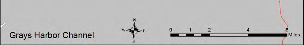
57 Figure 16. Inner harbor reaches of Grays Harbor Channel. 49


58 Figure 17. Outer harbor reaches of Grays Harbor Channel. 50
59 4.8 Westhaven Cove Small Boat Basin Entrance Channels PROJECT NAME Westhaven Cove Small Boat Basin AUTHORIZATION Breakwater facilities enclosing the Westhaven Cove Small Boat Basin were authorized by the Rivers and Harbors Act of 30 June 1948 (Pub. Law , 80 th Congress, 2 nd Session). Once the Port of Grays Harbor completed construction of the initial (northwest) entrance channel and the first component of berthing facilities within the boat basin in 1952, the United States assumed thereafter the obligation to maintain that 100 foot wide entrance channel to a depth of 16 feet MLW. Under the authority of Section 107 of the Rivers and Harbors Act of 1960 (Pub. Law , 86 th Congress, 2 nd Session), as amended, in 1979 the Corps constructed a second (southeast) entrance channel, a central access channel within the boat basin, and a turning basin, along with additional improvements to the breakwater facilities. All channel segments and the turning basin footprint are maintained to an authorized depth of 16 feet MLLW LOCATION Westhaven Cove is located near Point Chehalis on the east shore of Westport, Grays Harbor County, Washington. The harbor is home to Westport Marina and USCG Station Grays Harbor (Figure 18) PROJECT DESCRIPTION Project Area and Action Area The project area of the navigation channel is approximately 9 acres. The action area is Westhaven Cove Marina and extending one mile into Grays Harbor adjacent to the entrance channels in all directions. Purpose The purpose for the project is to maintain authorized depths at the two entrance channels to the Westport Marina and USCG station for safe transit of vessels. Maintenance of safe navigation through the entrance channels, single access channel, and turning basin is important because the fishing fleet moored in this marina is critical to the local economy. Navigation Features Westhaven Cove includes the Northwest Entrance Channel, Southeast Entrance Channel, an access channel to marina slips, and a turning basin in the southeast corner of the marina at the USCG station. The entrance channels are 100 to 200 feet wide and 16 feet deep plus two feet allowable overdepth during dredging; routine maintenance dredging may include an additional two feet of advance maintenance DREDGE AND DISPOSAL METHODS, QUANTITIES, FREQUENCY, AND DURATION Dredging may be conducted by either clamshell or hydraulic dredging method at this site. Hydraulic transport of material to the open water Point Chehalis aquatic disposal site would be 51
60 conducted via either a floating or submerged pipeline. The USACE estimates a need for removing up to 75,000 cy of sediment from both entrance and access channels and turning basin over each 10 year dredging interval. For each dredging event, the work would take approximately 14 to 21 days DISPOSAL SITES Material dredged from Westhaven Cove that is suitable for unconfined open water disposal would be placed at either the Point Chehalis or the South Jetty dispersive open water disposal sites IN-WATER WORK WINDOW The in water work window for the Westhaven Cove Small Boat Basin is 16 July through 31 January for Tidal Reference Area 15 at Westport CONSULTATION HISTORY This project has no ESA consultation history ACTION CONSULTED UPON Maintenance dredging of the channel prism described above at an interval of approximately 10 years, of a volume of up to 75,000 cy, via clamshell or hydraulic pipeline dredge with dredged material placed at one of the Grays Harbor aquatic multi user sites described above. 52
61 Figure 18. Navigation channels at Westhaven Cove Marina in Westport, Washington. 53
62 5 PROPOSED ACTION: BENEFICIAL USE DREDGED MATERIAL DISPOSAL SITES There are 10 beneficial use disposal sites in Western Washington (Table 5, Figure 19). There are two upland and one nearshore disposal sites in the Snohomish River delta at Everett, one nearshore disposal site adjacent to Keystone Harbor, three upland and nearshore sites adjacent to the mouth of the Quillayute River, and one upland and two nearshore disposal sites at the entrance to Grays Harbor. Locations are covered in detail in the following sections. Table 5. Beneficial use dredged material disposal site locations, disposal type, and disposal technique. Location Disposal Site Disposal Site Type Disposal Technique Everett Jetty Island Upland and nearshore zone; beneficial use for beach nourishment Hydraulic Pipeline, place onshore Everett Riverside Upland beneficial use Hydraulic Pipeline, place onshore Everett Site "O" Upland beneficial use Hydraulic Pipeline, place onshore Keystone Keystone Beach Upland and nearshore zone; beneficial use for beach nourishment Transport barge and front end loader; or hydraulic pipeline, place onshore Quillayute Site A Upland beneficial use Hydraulic Pipeline, place onshore Quillayute Quillayute Grays Harbor Site B (formerly sites 1 and 2A) First Beach Half Moon Bay Upland and nearshore zone; beneficial use for beach nourishment Upland and nearshore zone; beneficial use for beach nourishment Nearshore placement; beneficial use for shoreline nourishment Hydraulic Pipeline, place onshore Material moved from Site A via bulldozer Hopper Dredge Grays Harbor South Beach Nearshore placement; beneficial use for shoreline nourishment Hopper Dredge Grays Harbor Point Chehalis Revetment Extension Mitigation Site Upland beneficial use Pump ashore via Hopper Dredge 54

63 Figure 19. Beneficial use disposal sites used during maintenance dredging in Western Washington. Some navigation channels contain material that is unsuitable for open water disposal. This consultation only extends to suitable dredge material and any required dredging of unsuitable material will trigger a separate Section 7 consultation obligation. Some disposal sites are situated so that placement of clean dredged material contributes to the environment (beneficial use of dredged material). Possible uses include placing material to enhance beaches, replace eroded shoreline, soften armored shoreline, etc. Some dredged material is sufficiently clean that it is useful in 1) containing (capping) contaminated material; 2) nourishment of beaches and drift cells; and 3) creation of shallow water habitat. Sediment used for capping of contaminated material is not a part of this proposed action and would be addressed in a separate consultation. 55
64 Table 6. Amount of material placed in each Western Washington beneficial use dredged disposal site from 2003 through 2015 Location Disposal site Volume in cy Keystone Harbor Keystone Beach nearshore zone and upland 119,251 Snohomish Jetty Island nearshore zone and upland 423,317 Snohomish Riverside upland 125,000 Snohomish Site "O" upland 256,389 Quillayute Site 1 nearshore zone and upland 88,672 Quillayute Site 2A nearshore zone and upland 134,406 Quillayute Site A upland 32,575 Quillayute First Beach nearshore zone 5,000 Grays Harbor Half Moon Bay nearshore zone 1,481,845 Grays Harbor South Beach nearshore zone 2,049,484 Grays Harbor Point Chehalis Revetment Extension Mitigation Site upland 135,705 Quillayute sites 1 and 2A will be combined into one large site, renamed site B, for future disposal actions. 5.1 Snohomish River Beneficial Use Disposal Sites There are three beneficial use disposal sites at Port Gardner in the Snohomish River delta area adjacent to the City of Everett. These include Jetty Island, Riverside, and Site O (Figure 20). Table 6 lists the amount of material placed in each disposal site since Jetty Island is an example of beneficial use of dredge material. Jetty Island was artificially created by disposing material on the western side of a rock and wood revetment that protected the Everett shoreline. The sandy dredged material that constitutes Jetty Island is indistinguishable from the material that makes up the Snohomish River delta, thus Jetty Island provides increased natural habitat Jetty Island Beneficial Use Disposal Site The location of Jetty Island appears in Figure 20. Jetty Island was created by placing dredged material on the west side of a wood jetty originally constructed to protect the Everett commercial waterfront from storm waves (Figure 21). Based on available records, the USACE constructed a wood pile jetty in 1901 (some of the wood jetty was later replaced with rock) seaward of the portion of the Port of Everett that was exposed to the open waters of Port Gardner. Dredged material removed from the adjacent navigation channel between the Port of Everett and the jetty was placed on the west side of the wood/rock jetty as a disposal site; this began in about Subsequently Jetty Island grew from these beginnings and eventually buried most of the jetty, except for the southern end, which is still exposed. Thus, Jetty Island came about because of disposal of maintenance dredged material. Figure 21 is a picture of the Everett waterfront taken in 1902 showing the jetty. 56

65 Figure 20. Port Gardner (Everett) beneficial use disposal site locations. The Jetty Island disposal site is generally the southern half of the island. Placement of material on Jetty Island is considered beneficial use of dredged material. The primary purposes for placing material on Jetty Island are for stabilization of the jetty and for suppression of the nonnative, invasive Scot s broom (Cytisus scoparius). Additionally, the sediment is beneficial for salmon habitat. Nearshore habitat has been identified as a limiting factor for salmon recovery in this basin; therefore, material is occasionally placed at Jetty Island as beneficial use in the nearshore zone. Dredged material (typically sand) is placed on the island via a hydraulic pipeline dredge. The USACE and the Port of Everett placed approximately 323,000 cy of clean sediment along the western portion of the island in 1989 as a 1,500 foot long berm to balance erosion losses from the west side of the island and to create protected intertidal marsh and mudflat habitat as well as a lagoon to enhance species diversity and provide salmon habitat. Monitoring has shown the berm has created valuable mudflat habitat for benthic invertebrates that improved the food supply and habitat value of Jetty Island for juvenile salmon, forage fish, and shore birds (Pentec 2000). However, since there is no natural source of sediment to nourish the berm, continued nourishment of the berm will be necessary to prevent its gradual erosion and to maintain the habitats created by the berm and adjacent areas of Jetty Island. 57

66 Figure 21. Everett waterfront in 1902 showing the jetty before it was buried with dredge material creating Jetty Island, which protects the exposed waterfront. The project area is Jetty Island, the shoreline out to 30 feet MLLW on the marine side, and the adjacent mouth of the Snohomish River. Placement of dredged materials occurs from the top of the existing beach at an approximate elevation of +15 downslope to +1 feet MLLW with a 10:1 slope tying into the existing grade of adjacent beach (Figure 22). Placement is unconfined in the nearshore zone and materials are allowed to settle out and naturally disperse. Up to about 1,250,000 cy could be placed in the disposal site over the next 25 years. Jetty Island disposal is typically conducted biennially, although the frequency could vary based on factors such as shoaling rates and available budget. Up to 40,000 cy is expected to be placed at Jetty Island per episode. The in water work window as approved by NMFS is 16 October through 14 February to protect juvenile Chinook salmon and bull trout. The pipeline placed across Jetty Island normally runs along a public path to minimize effects to vegetation. The pipeline route avoids the high salt marsh located several hundred feet to the north. Dredged material is placed only on uplands dominated by grasses, as well as the supratidal and upper intertidal zones, and the grasses are replanted following placement of the dredged material. However, the path is often flooded under several feet of water and requires placing the pipe farther north through the uplands dominated by Scot s broom. No impacts to aquatic vegetation or other habitats in the nearshore zone will result from placement of dredged material on Jetty Island. 58


67 Figure 22. Dredged material placement area on Jetty Island. 59
68 5.1.2 Riverside Disposal Site The Riverside Disposal site is located on the left bank of the Snohomish River at about river mile 4.8 (Figure 20). Sediment hydraulically dredged from the upstream settling basin and adjacent portion of the channel would be placed directly onto the 8 acre southern portion of the Riverside Business Park. The material is subsequently collected and moved via truck by the Port for use at the Riverside site or other regional sites in need of fill material. Up to about 350,000 cy could be placed in the disposal site over the next 25 years. Disposal at the Riverside site is typically biennial, although the frequency can vary based on factors such as shoaling rates and available budget. Up to 40,000 cy is expected to be placed at the Riverside site per episode. A small work vessel tows a plastic pipeline to the site during high tide. A wire rope or strap attached to the pipe allows a dozer to pull the pipe up and over the containment berm, which has been constructed with on site materials. The hydraulic pipeline extends from the dredge positioned in the upper settling basin, runs along the left bank river channel, over the salt marsh and riparian berm, and into the Riverside site. Dredged material composed of a slurry of sediment and water is pumped from the dredge to the site. Turbidity levels of discharged decant water are monitored and managed in accordance with the conditions of the CWA Section 401 water quality certification issued by the Washington Department of Ecology. Dredgers take great care during placement of the pipeline to minimize impacts to intertidal salt marsh and riparian vegetation along the shoreline to the greatest extent feasible. The salt marsh plants will be in winter dormancy during the approximately three to four week period when the pipeline would be resting on the marsh and the pipeline does not move once in place. Berms of sand surrounding the basin separate the dredged material from the riparian edge of the river by containing the water/sediment slurry. The disposal site is devoid of vegetation except for upland grasses, slopes gradually downward to the north. The slurry slowly flows downgradient toward the outlet weirs. As the sediment settles out, the water continues flowing until the water flows through a system of weirs and returns to the river. The Port of Everett determines the ultimate fate of the material. The project area for this disposal site is the 8 acre Riverside beneficial use disposal site and the adjacent river for one mile downstream of the disposal site Site O Disposal Site This site is located on the upland shore adjacent to the Snohomish River (Figure 20) at approximately river mile four. Sediment hydraulically dredged from the upstream settling basin in the Snohomish River and adjacent portion of the channel is placed directly onto the southeastern corner 9 acre portion of Site O (formerly known as Kimberly Clark log yard) site. The sediment is subsequently re handled (collected and moved via truck) by the City or Port for use at other regional sites in need of fill material. Up to 650,000 cy could be placed in the disposal site over the next 25 years. The method of placement is similar to the sediment placement at Riverside Business Park site (please see the Riverside section above); although Site O has no salt marsh. Site O disposal is typically conducted biennially, although the frequency could vary based on factors such as shoaling rates and available budget. Up to 150,000 cy is expected to be placed at the Site O per episode. The City or Port of Everett determines the fate of the material placed in Site O. 60
69 The project area is the 9 acre portion of the Parcel O disposal site and the adjacent river for one mile downstream of the disposal site. 5.2 Keystone Beach Beneficial Use Disposal Site Disposal of dredged material occurs on the previously used Keystone Beach disposal site (Figure 23), located on the shoreline just east of the jetty protecting the east side of the entrance channel to Keystone Harbor. The disposal site is approximately 2.5 acres in the supratidal and upper intertidal zone. All dredged material beneficially re nourishes the section of the beach to the east of Keystone Harbor (Figure 24). The project area for the Keystone Beach disposal site is the area of the 2.5 acre disposal site, the shoreline out to 30 feet MLLW and continuing down current for one mile. The dredged material is placed during low tide to replace lost intertidal material when no ESA listed species are present. The method used to deposit material on the beach depends on the dredge equipment. With hydraulic dredging, the material is pumped to the beach area. To minimize effects to water quality from the discharge from hydraulic dredge, berms created from local material preclude effluent from flowing directly into Puget Sound before the water fraction filters through the berm. Dredged material is graded mechanically to match the natural beach profile and remove any mounds and depressions that may cause injuries to the public. With mechanical dredging, the sediment is loaded onto flat deck barges. Once filled, the barges are pushed near the beach (grounding is not permitted), and the dredged material offloaded using the clamshell bucket to move the material onto the high ground staging area where any water remaining in the material quickly seeps into the porous substrate. Material is subsequently transported with terrestrial equipment (e.g. front end loader) to the nearby beach disposal site where no berms or dewatering methods are required due to the prior decanting on the barge and on shore. The approved in water construction window is 16 July through 15 February. Up to 165,000 cy could be placed in the disposal site over the next 25 years, with up to 50,000 cy expected to be placed per episode. 61


70 Figure 23. Keystone Harbor and the adjacent Keystone Beach beneficial use disposal site. Figure 24. Dredged material disposal area for beach nourishment to protect park infrastructure at risk of damage from shoreline erosion. 62
71 5.3 Quillayute River Beneficial Use Disposal Sites All disposal sites at Quillayute are located in the nearshore zone or adjacent upland (Figure 13 in Chapter 4). Dredging is by hydraulic dredge allowing direct placement of material onto beneficial use disposal sites. Dredged material is used beneficially to maintain the spit that separates the lower portion of the Quillayute River from the Pacific Ocean. The Quillayute Spit runs parallel along the west bank of the lower Quillayute River, maintains the river in its current channel, and prevents Pacific Ocean waves from flooding the La Push boat basin and village. The beneficial placement of dredged material helps maintain the spit by replenishing the eroded sand adjacent to the structure. The dredged material placed onto the spit maintains the sediment balance within the system, maintaining spawning habitat for surf smelt and an additional benefit of providing protection to the navigation structures by reducing the erosive effects from ocean waves undermining the structures. No ESA listed species or designated critical habitat occur in the disposal sites. There are no potential effects from disposal on any listed species or designated critical habitat. These disposal sites are included in this BA for information only and provide a record of deposited dredged material. The established work windows for the disposal sites at the Quillayute River are 1 September through 28 February for Site A, 1 October through 28 February for new disposal Site B (formerly Sites 1 and 2A), and material cannot be placed on First Beach until after 1 November continuing through 28 February Former Disposal Sites 1 and 2A Former Site 1 is located on the western side of Quillayute spit and is used in conjunction with former Site 2A for placement of material on the spit (Figure 13). This location is used to keep riverborne material within the nearshore environment and to enhance the integrity of Quillayute Spit. The two existing sites are approximately 300 feet apart and near the southern terminus of the spit. Site 1 is 1.2 areas and 2A is 1.61 acres. Dredged material placement is typically via hydraulic pipeline dredge with the outlet just over the crest of the jetty armoring and above MHHW (+8.45 feet MLLW at this location) to minimize suspended sediment in the water. Material that enters the water directly, primarily during higher tides, moves along by longshore currents and deposits in the intertidal zone further down current to the north. The names of these two sites are now obsolete as the USACE is proposing to combine and lengthen the disposal areas to become disposal Site B Disposal Site B Wave action continues to damage various areas along the entire Quillayute spit, eroding material from the toe of the riprap. The USACE is proposing to merge Sites 1 and 2A, and increase the overall footprint to stretch from the northern end to the southern end of the riprapped spit. The new disposal site is designated Site B. Site B will be approximately 3,000 feet long, 75 feet wide, with an area of approximately 6 acres. Up to 75,000 cy per dredge episode placed in various locations within Site B and up to 975,000 cy over the next 25 years assuming dredging occurs every two years. The focus for 63
72 each placement event will be limited to those areas identified in need of nourishment. The method of placement will continue to be that described for former Sites 1 and 2A. Site B will keep riverborne material within the nearshore environment. The fate of the material will enhance the shoreline in the drift cell down current of the disposal site and buttress the protective spit. The area of analysis includes the 6 acre Site B, the marine shoreline out to 30 feet MLLW and continuing down current (northward) of the disposal site for 1 mile Disposal Site A Site A is a 1.75 acre site on the Quileute Tribe s reservation at the southwest corner of the town of La Push (Figure 25). The portion of the area used for material placement has capacity for approximately 15,000 cy per placement episode. Up to 180,000 cy could be placed in the disposal site over the next 25 years. Dredged material is typically placed via hydraulic pipeline dredge. The contractor uses a dozer and/or excavator to create a suitably sized basin and then uses the onsite material to surround the basin with a berm. The basin inside the berm will be of sufficient size to allow turbid water to settle, before allowing the water to return to the Quillayute River through an outfall weir that directs the clean water onto riprap to prevent shoreline erosion. Turbidity levels of discharged decant water are monitored and managed in accordance with the conditions of the CWA Section 401 water quality certification issued by the Washington Department of Ecology. The material has been used by the Quileute Tribe for construction purposes in the past, but in recent years has been used at First Beach to protect the jetty root as described in the following section. Material at Site A may be placed after 1 November onto First Beach to protect the root of the south jetty that erodes during coastal storm events at the discretion of the USACE. Material that is not placed onto First Beach may be available for tribal reuse in upland areas. The area of analysis for the Site A disposal site is the area of the 1.75 acre disposal site and the Quillayute River down current for one mile First Beach Disposal Site Up to 15,000 cy of dredged material placed per episode in upland Site A is pushed onto the sloped bank at First Beach (Figure 25) with a dozer. The area of the First Beach site is 1.51 acres. Once fully decanted, the dredged material is transported over the top of the bank at First Beach down to where it intersects the shoreline, not to extend below MLLW. A dozer grades the material to a slope varying between 5:1 and 20:1 depending on height of the bank and quantity of available material. This placement is usually done during the month of November. Once in place, the material moves with natural erosive forces (wave action and longshore currents) to assume its final contours and sediment gradations. The material placed consists of sand with a small fraction of gravel and cobble from the outer river channel. The purpose of delaying the material placement until early November is twofold: 1) it will avoid surf smelt spawning and emergence, and 2) it will allow the material to dry for approximately one to two months. Placing dry material on the beach will prevent elevated levels of turbidity in the waters surrounding First Beach. In 2012, 5,000 cy was placed at this site. Up to 180,000 cy could be placed in this site over the next 25 years. The purpose for placement is to protect the south jetty at First Beach. The area of analysis for the First Beach disposal site is the 1.51 acre disposal site and into the adjacent ocean waters out to 30 feet MLLW and continuing down current for one mile. 64

. Material placed in these sites is outer harbor material derived from marine sources (Figure 26).")

73 Figure 25. Location, footprint, and grading profile of material placed at First Beach. 5.4 Grays Harbor Beneficial Use Disposal Sites The USACE places material at three beneficial use disposal sites in Grays Harbor. Two of these sites are subtidal nearshore zone (Half Moon Bay and South Beach) and one is upland at the Point Chehalis Revetment Extension Mitigation Site (Mitigation Site). Material placed in these sites is outer harbor material derived from marine sources (Figure 26). Disposal at these locations was discussed in the completed consultation document through 2026 (USACE 2011b) and a supplemental biological assessment with letters of concurrence for deepening and postdeepening maintenance in Consultation in this document is intended to extend the postdeepening consultation coverage from 2026 through


74 Figure 26. Grays Harbor Beneficial Use Sites. Dredged material placed in the Half Moon Bay beneficial use site enhances the nearshore area of Half Moon Bay. South Beach beneficial use site is located in the Pacific Ocean adjacent to the South Jetty and just offshore of the beach in that area. Material placed in the South Beach site enters the littoral transport system and helps maintain the local beaches. The Mitigation Site is an upland site, located adjacent to the Half Moon Bay Beach. It is intended to maintain a stable beach profile and to ensure that the armor stone of the revetment extension is not exposed to wave action. The determination of which disposal site will be used during the course of maintenance dredging is based on several factors, including the following: weather and wave conditions at the time of disposal; presence of commercial crab pots in a disposal site and/or access lane; and dredge capability to place material upland. Dredged material placed in the beneficial use disposal sites is typically dredged and transported via hopper dredge, but could on occasion be dredged and transported via bottom dump barge where tugs move the bottom dump barges to and from the aquatic beneficial disposal sites. 66
Introduction Proposed Action
 Introduction The United States Navy s Naval Special Warfare Group THREE of the Naval Special Warfare Command proposes to conduct training at multiple Western Washington locations. The purpose of the training
Ocean Structures and Material Prof. Dr. Srinivasan Chandrasekaran Department of Ocean Engineering Indian Institute of Technology, Madras
 Ocean Structures and Material Prof. Dr. Srinivasan Chandrasekaran Department of Ocean Engineering Indian Institute of Technology, Madras Module - 2 Lecture - 5 Dredging II In the fifth lecture we discussed
The Blue Heron Slough Conservation Bank
 1 The Blue Heron Slough Conservation Bank CONSERVATION BANKING July 19-23, 2010 CASE STUDY SERIES The Blue Heron Slough Conservation Bank (Washington) I. OVERVIEW & BACKGROUND: Location: Snohomish River
Dredging Keeping Our Underwater Highways Open
 Dredging Keeping Our Underwater Highways Open Sedimentation Material that falls to the bottom of a liquid is called sediment. If enough sediment deposits to build a shallow spot on the river or ocean bottom,
Nome Harbor Page 2 of 12
 Nome Harbor Nome Harbor Page 2 of 12 Condition of Improvements 30 December 2015 Nome Harbor, Alaska (CWIS No. 010422, 012270, 072742, 087755) Authorization (1) Rivers and Harbors Act, 8 August 1917 (House
30 DAY PUBLIC NOTICE MAINTENANCE DREDGING OF THE 8-FOOT CHANNEL OF THE FEDERAL NAVIGATION PROJECT IN KENNEBUNK RIVER KENNEBUNK & KENNEBUNKPORT, ME
 fr.iiif.i ~ US Anny Corps of Engineers New England District 696 Virginia Road Concord, MA 01742-2751 Public Notice In Reply Refer to: Mr. Jack Karalius nae-pn-nav@usace.army.mil Programs/Project Management
1-32 NOME HARBOR, ALASKA (CWIS NOS , 87755, 12270, & 10422) Condition of Improvement 30 September 2012
 Condition of Improvement 30 September 2012") NOME HARBOR 1-32 NOME HARBOR, ALASKA (CWIS NOS. 72742, 87755, 12270, & 10422) Condition of Improvement 30 September 2012 AUTHORIZATION: (1) Rivers and Harbors Act, 8 August 1917 (House Doc. 1932, 64th
NOME HARBOR 1-32 NOME HARBOR, ALASKA (CWIS NOS. 72742, 87755, 12270, & 10422) Condition of Improvement 30 September 2012 AUTHORIZATION: (1) Rivers and Harbors Act, 8 August 1917 (House Doc. 1932, 64th
Ninilchik Harbor Page 2 of 11
 Ninilchik Harbor Ninilchik Harbor Page 2 of 11 Condition of Improvements 31 December 2017 Ninilchik Harbor, Alaska (CWIS No. 012640, 087345) Authorization Rivers and Harbors Act, 3 July 1958 (P.L. 85-500
APPENDIX M DREDGED MATERIAL MANAGEMENT PLAN (DMMP) FINAL INTEGRATED FEASIBILITY REPORT AND ENVIRONMENTAL ASSESSMENT
 FINAL INTEGRATED FEASIBILITY REPORT AND ENVIRONMENTAL ASSESSMENT") APPENDIX M DREDGED MATERIAL MANAGEMENT PLAN (DMMP) Brazos Island Harbor, Texas Channel Improvement Study FINAL INTEGRATED FEASIBILITY REPORT AND ENVIRONMENTAL ASSESSMENT This page is intentionally left
APPENDIX M DREDGED MATERIAL MANAGEMENT PLAN (DMMP) Brazos Island Harbor, Texas Channel Improvement Study FINAL INTEGRATED FEASIBILITY REPORT AND ENVIRONMENTAL ASSESSMENT This page is intentionally left
Grays Harbor O&M and Deepening Dredging
 Grays Harbor O&M and Deepening Dredging Elizabeth Chien Project Manager Seattle District 28 January 2016 US Army Corps of Engineers Grays Harbor Navigation Channel Inner Harbor O&M Dredging Summer 2015:
Condition of Improvements 30 December 2014 Wrangell Harbors, Alaska (CWIS No , )
") Wrangell Harbors Condition of Improvements 30 December 2014 Wrangell Harbors, Alaska (CWIS No. 010435, 021500) Authorization (1) Rivers and Harbors Act, 22 September 1922 (House Doc. 161, 67th Congress,
Wrangell Harbors Condition of Improvements 30 December 2014 Wrangell Harbors, Alaska (CWIS No. 010435, 021500) Authorization (1) Rivers and Harbors Act, 22 September 1922 (House Doc. 161, 67th Congress,
MOREHEAD CITY HARBOR, NC. Dredged Material Management Plan (DMMP)
") MOREHEAD CITY HARBOR, NC Dredged Material Management Plan (DMMP) Public Meeting/Info Session 15 January 2014 US Army Corps of Engineers Morehead City Harbor DMMP Presentation Topics Morehead City Harbor
MOREHEAD CITY HARBOR, NC Dredged Material Management Plan (DMMP) Public Meeting/Info Session 15 January 2014 US Army Corps of Engineers Morehead City Harbor DMMP Presentation Topics Morehead City Harbor
Listed species under the jurisdiction of NOAA Fisheries that occur in the geographic area of responsibility of the Wilmington District are:
 Information to assist in compliance with Nationwide Permit General Condition 18, Endangered Species Required Reporting via Pre-Construction Notification The purpose of this document is to provide information
Public Notice U.S. Army Corps In Reply to Application Number CENAB-OP-RMS (NATIONAL HARBOR (FORMERLY PORT Baltimore District AMERICA])
![Public Notice U.S. Army Corps In Reply to Application Number CENAB-OP-RMS (NATIONAL HARBOR (FORMERLY PORT Baltimore District AMERICA])](/thumbs/89/100795623.jpg "Public Notice U.S. Army Corps In Reply to Application Number CENAB-OP-RMS (NATIONAL HARBOR (FORMERLY PORT Baltimore District AMERICA])") Public Notice U.S. Army Corps In Reply to Application Number of Engineers CENAB-OP-RMS (NATIONAL HARBOR (FORMERLY PORT Baltimore District AMERICA]) 88-01361 PN 14-05 Comment Period: January 16, 2014 to
Public Notice U.S. Army Corps In Reply to Application Number of Engineers CENAB-OP-RMS (NATIONAL HARBOR (FORMERLY PORT Baltimore District AMERICA]) 88-01361 PN 14-05 Comment Period: January 16, 2014 to
Essential Fish Habitat Consultation
 1 Essential Fish Habitat Consultation Marine Shoreline Development Workshop February 21, 2007 John H. Stadler Washington State Habitat Office National Marine Fisheries Service Magnuson-Stevens Fishery
Admiralty Inlet Pilot Tidal Project FERC No Appendix C. Derelict Gear Monitoring Plan
 Appendix C Derelict Gear Monitoring Plan ADMIRALTY INLET PILOT TIDAL PROJECT FERC PROJECT NO. 12690 DERELICT GEAR MONITORING PLAN (submitted with the Final Application for a New Pilot Project License)
1-32 NOME HARBOR, ALASKA (CWIS NOS , 87755, & 10422) Condition of Improvement 30 September 2009
 Condition of Improvement 30 September 2009") NOME HARBOR 1-32 NOME HARBOR, ALASKA (CWIS NOS. 72742, 87755, & 10422) Condition of Improvement 30 September 2009 AUTHORIZATION: (1) Rivers and Harbors Act, 8 August 1917 (House Doc. 1932, 64th Congress,
NOME HARBOR 1-32 NOME HARBOR, ALASKA (CWIS NOS. 72742, 87755, & 10422) Condition of Improvement 30 September 2009 AUTHORIZATION: (1) Rivers and Harbors Act, 8 August 1917 (House Doc. 1932, 64th Congress,
Grays Harbor Federal Project
 Grays Harbor Federal Project Elizabeth Chien Coastal Navigation Program Manager Seattle District 27 October 2016 US Army Corps of Engineers Grays Harbor Navigation Channel Inner Harbor Dredging Summer
Cordova Harbor Page 2 of 9
 Cordova Harbor Cordova Harbor Page 2 of 9 Condition of Improvements 30 December 2017 Cordova Harbor, Alaska (CWIS No. 087136, 087186, 087711) Authorization Rivers and Harbors Act, 30 August 1935 (R & H
ST. LOUIS SECTION PROJECT OF THE YEAR AWARD
 ST. LOUIS SECTION PROJECT OF THE YEAR AWARD Originality and Innovation The St. Louis Harbor Project is located in the Upper Mississippi River between the entrance to the Chain of Rocks Canal at River
Planning Considerations for Nearshore Placement of Mixed Dredged Sediments
 Planning Considerations for Nearshore Placement of Mixed Dredged Sediments PURPOSE: Dredging planning and management decisions are based on a combination of engineering and economic factors tempered by
Juneau Douglas Harbor
 Juneau Douglas Harbor Douglas Harbor Page 2 of 8 Condition of Improvements 31 December 2015 Douglas Harbor, Alaska (CWIS No. 072789, 180942) Authorization Rivers and Harbors Act, 3 July 1958 (House Doc.
Information To Assist In Compliance With Nationwide Permit General Condition 18, Endangered Species
 Information To Assist In Compliance With Nationwide Permit General Condition 18, Endangered Species This document implements one of the protective measures identified in the November 24, 2014 programmatic
APPROVED WORK WINDOWS FOR FISH PROTECTION FOR ALL MARINE/ESTUARINE AREAS. excluding THE MOUTH OF THE COLUMBIA RIVER (BAKER BAY)
") APPROVED FOR FISH PROTECTION FOR ALL MARINE/ESTUARINE AREAS excluding THE MOUTH OF THE COLUMBIA RIVER (BAKER BAY) BY August 21, 2017 (1) The general work window is given by Tidal Reference Area. Figure
APPROVED FOR FISH PROTECTION FOR ALL MARINE/ESTUARINE AREAS excluding THE MOUTH OF THE COLUMBIA RIVER (BAKER BAY) BY August 21, 2017 (1) The general work window is given by Tidal Reference Area. Figure
APPENDIX G DREDGING STUDIES. G.1: Fish Related Dredgi g I pacts a d Mitigatio
 APPENDIX G DREDGING STUDIES G.1: Fish Related Dredgi g I pacts a d Mitigatio A acis Isla d WWTP Ne Outfall Syste Va cou er Fraser Port Authority Project a d E iro e tal Re ie Applicatio This page intentionally
Puget Sound Shorelines. Waves and coastal processes. Puget Sound shorelines: Effects of beach armoring
 Puget Sound Shorelines Puget Sound shorelines: Effects of beach armoring Waves and coastal processes Factors affecting wave energy hitting the coast Processes transporting sediment along coastlines What
Ocean Structures and Materials Prof. Dr. Srinivasan Chandrasekaran Department of Ocean Engineering Indian Institute of Technology, Madras
 Ocean Structures and Materials Prof. Dr. Srinivasan Chandrasekaran Department of Ocean Engineering Indian Institute of Technology, Madras Module - 2 Lecture - 4 Dredging I (Refer Slide Time: 00:22) The
Shoalwater Bay Shorline Erosion Dredging
 Shoalwater Bay Shorline Erosion Dredging ROSS ISLAND SAND & GRAVEL CO. Saving the Tokeland Penninsula Willapa Bay & Tokeland Penninsula Southwestern Washington Coast Shoalwater Bay Historic View Settlements
Charlottetown Marine Terminal Pipeline Decommissioning Project Description
 Charlottetown Marine Terminal Pipeline Decommissioning Project Description 69 Marr Road Unit B Rothesay NB, E2E 3J9 Tel (506) 848-1920 Fax (506) 848-1929 Charlottetown Marine Terminal Pipeline Decommissioning
Species Conclusions Table
 Conclusions Table Project Name: Chesapeake Landing HOA- Breakwaters (NAO-14-0283) Date: February 25, 2014 /Resource Name Loggerhead sea turtle (Caretta caretta) Conclusion ESA Section 7 / Eagle Act Determination
Union Pacific Railroad
 Input Questions: 404/401 Pre Application Meeting, December 18, 2013, Portland, Oregon 1. What is the project purpose and need? The purpose of the project is to improve the efficiency and average velocity
United States Department of the Interior
 United States Department of the Interior John Kennelly, Chief Planning Branch Department of the Army New England District U.S. Army Corps of Engineers 696 Virginia Rd Concord, Massachusetts 01742 FISH
CLARIFICATION PAPER DREDGED MATERIAL VOLUME ESTIMATES
 CLARIFICATION PAPER DREDGED MATERIAL VOLUME ESTIMATES Prepared by Hiram Arden (Corps of Engineers), David Fox (Corps of Engineers) and Ted Benson (DNR) for the PSDDA agencies. INTRODUCTION In a PSDDA sediment
Protectingpipelinesfor
 24 Protectingpipelinesfor Michael Paulin, Damien Humby and Joseph Cocker, INTECSEA Canada, and Glenn Lanan, INTECSEA Inc., describe the process of trenching for the protection of pipelines in ice environments.
Essential Fish Habitat
 Pacific Fishery Management Council Fact sheet: Essential Fish Habitat Habitat is the environment where an animal lives, feeds, and reproduces. Identifying fish habitat is complex because fish move through
Nearshore Dredged Material Placement Pilot Study at Noyo Harbor, CA
 1 Nearshore Dredged Material Placement Pilot Study at Noyo Harbor, CA Noyo Cove N 2011 National Conference on Beach Preservation Technology 9-11, February 2011 Lihwa Lin, Honghai Li, Mitchell Brown US
SACO RIVER AND CAMP ELLIS BEACH SACO, MAINE SECTION 111 SHORE DAMAGE MITIGATION PROJECT APPENDIX F ECONOMIC ASSESSMENT
 SACO RIVER AND CAMP ELLIS BEACH SACO, MAINE SECTION 111 SHORE DAMAGE MITIGATION PROJECT APPENDIX F ECONOMIC ASSESSMENT Department of the Army New England District, Corps of Engineers 696 Virginia Road
CORPS FACTS. Harbor Dredging U.S. ARMY CORPS OF ENGINEERS BUILDING STRONG
 CORPS FACTS Harbor Dredging U.S. ARMY CORPS OF ENGINEERS BUILDING STRONG Disaster Response Sedimentation in the channel is caused by the normal cycle of silt movement, erosion from high water or heavy
14 NOISE AND VIBRATION
 14 NOISE AND VIBRATION 14.1 EXISTING ENVIRONMENT 14.1.1 The noise environment within Poole Harbour is generally characterised by low to medium noise levels depending on location. For example, certain areas
Assateague Island National Seashore North End Restoration Project Timeline
 Assateague Island National Seashore North End Restoration Project Timeline Date Event Some information provided in the Project Introduction document. Detailed events are available in a timeline compiled
Blakely Island, N Thatcher Bay. Restoration Recommendation: Rank Score (total score)
") Soft Shore Protection/Structure Removal Blueprint for San Juan County Forage Fish Beaches Appendix 2: Recommendations for sites scoring below the top ten, sorted by island (east to west) Blakely Island,
Soft Shore Protection/Structure Removal Blueprint for San Juan County Forage Fish Beaches Appendix 2: Recommendations for sites scoring below the top ten, sorted by island (east to west) Blakely Island,
New Jersey Coastal Zone Overview. The New Jersey Beach Profile Network (NJBPN) 3 Dimensional Assessments. Quantifying Shoreline Migration
 3 Dimensional Assessments. Quantifying Shoreline Migration") New Jersey Coastal Zone Overview The New Jersey Beach Profile Network (NJBPN) Objectives Profile Locations Data Collection Analyzing NJBPN Data Examples 3 Dimensional Assessments Methodology Examples Quantifying
New Jersey Coastal Zone Overview The New Jersey Beach Profile Network (NJBPN) Objectives Profile Locations Data Collection Analyzing NJBPN Data Examples 3 Dimensional Assessments Methodology Examples Quantifying
Unalaska Navigation Channel Improvements
 1 237 237 237 255 255 255 0 0 0 Unalaska Navigation Channel Improvements 217 217 217 200 200 200 163 163 163 131 132 122 239 65 53 80 119 27 252 174.59 110 135 120 112 92 56 62 102 130 102 56 48 130 120
La Quinta Channel Extension Port of Corpus Christi Ingleside, Texas. Mark Coyle
 La Quinta Channel Extension Port of Corpus Christi Ingleside, Texas Mark Coyle Corpus Christi Navigation Channel PCCA La Quinta Expansion Project History Corpus Christi Ship Channel Improvement Projects
CHAPTER 4: BEST MANAGEMENT PRACTICES FOR EROSION AND SEDIMENTATION CONTROL
 Figure 4.4m. Type III Floating Turbidity Barrier Source: American Boom and Barrier Corporation and Virginia Department of Transportation (DOT) Standard Sheets 71 4.4.6 Floating Turbidity Barrier Definition
CHAPTER 4 DESIRED OUTCOMES: VISION, GOALS, AND OBJECTIVES
 CHAPTER 4 DESIRED OUTCOMES: VISION, GOALS, AND OBJECTIVES Vision One of the first steps in developing this Plan was articulating a vision - a clear statement of what the Plan strives to achieve and what
Delaware Chapter Surfrider Foundation - Indian River Inlet Monitoring
 Delaware Chapter Surfrider Foundation - Indian River Inlet Monitoring In 2012, the Delaware Surfrider Foundation Chapter formed the Surf Quality and Access Committee to focus on issues such as surf spot
3.9 Marine Transportation
 3.9 Marine Transportation 3. Affected Environment and Environmental Analysis 3.9 Marine Transportation 3.9.1 Introduction This section describes existing marine vessel transportation within the Port, the
SPECIALISED SERVICES. Kris Vlaeminck, Jan De Nul Group, Luxembourg, explains the use of dredging vessels on the Macedon Project in Australia.
 SPECIALISED SERVICES Kris Vlaeminck, Jan De Nul Group, Luxembourg, explains the use of dredging vessels on the Macedon Project in Australia. Figure 1. Shore approach for the Macedon project in Australia.
TABLE OF CONTENTS LEGAL NOTICE
 Closure Plan for Existing CCR Rev. 0 Surface Impoundments Page No. i TABLE OF CONTENTS 1. INTRODUCTION AND PURPOSE... 1 2. CLOSURE PLAN NARRATIVE DESCRIPTION... 2 3. FINAL COVER SYSTEM DESCRIPTION... 3
APPLICANT: Pacific Northwest National Laboratory Attention: Mr. Charles Brandt 1529 West Sequim Bay Road Sequim, Washington 98382
 US Army Corps of Engineers Seattle District Joint Public Notice Application for a Department of the Army Permit and a Washington Department of Ecology Water Quality Certification and/or Coastal Zone Management
Feasibility Study for Restoration of Titlow Lagoon Fish Passage. South Puget Sound Salmon Enhancement Group
 Feasibility Study for Restoration of Titlow Lagoon Fish Passage South Puget Sound Salmon Enhancement Group January 2010 Feasibility Study for Restoration of Titlow Lagoon Fish Passage Prepared for South
Sediment Management Plan Rehoboth Bay
 Sediment Management Plan Rehoboth Bay STAC Meeting November 16, 2007 Goals of the Study Improve planning for future dredging needs Reduce the dependency on dredging Study Tasks Environmental data Historical
Maltester Channel Dredging. Shoreline Marina Committee. November 18, 2008
 Maltester Channel Dredging Shoreline Marina Committee November 18, 2008 Shoaling Study Summary Report Completed in October 2008 Analyzed siltation rates at Marina Rate of siltation is dynamic ranging from
1-44. SITKA HARBOR, ALASKA (Western Channel, Crescent Bay Basin, Channel Rock Breakwaters) (CWIS NOS , 16840, 10322, 55030, 13787)
 (CWIS NOS , 16840, 10322, 55030, 13787)") SITKA 1-44 SITKA HARBOR, ALASKA (Western Channel, Crescent Bay Basin, Channel Rock Breakwaters) (CWIS NOS. 72845, 16840, 10322, 55030, 13787) Condition of Improvement 30 September 2011 AUTHORIZATION:
SITKA 1-44 SITKA HARBOR, ALASKA (Western Channel, Crescent Bay Basin, Channel Rock Breakwaters) (CWIS NOS. 72845, 16840, 10322, 55030, 13787) Condition of Improvement 30 September 2011 AUTHORIZATION:
NATIONAL MARINE FISHERIES SERVICE REPORT ON PACIFIC HALIBUT CATCH SHARING PLAN CHANGES FOR 2015
 Agenda Item G.1.b Supplemental NMFS Report 1 November 2014 NATIONAL MARINE FISHERIES SERVICE REPORT ON PACIFIC HALIBUT CATCH SHARING PLAN CHANGES FOR 2015 Table of Contents Purpose of the document... 2
DRAFT TECHNICAL MEMORANDUM
 DRAFT TECHNICAL MEMORANDUM From: File No.: 213.001 Re: Beaux Arts Village Shoreline - 2016 Introduction The Washington Academy of Beaux Arts (WABA) completed shoreline habitat restoration at three locations
X.B WETLANDS ROGUE RIVER ESTUARY
 X.B WETLANDS ROGUE RIVER ESTUARY The Rogue River has a drainage area of 5,100 square miles, yet the estuary of the Rogue River is one of the smallest in Oregon, measuring approximately 1,880 acres during
Proposed Terrestrial Critical Habitat for the Northwest Atlantic Loggerhead Sea Turtle Population. U.S. Fish and Wildlife Service
 Proposed Terrestrial Critical Habitat for the Northwest Atlantic Loggerhead Sea Turtle Population U.S. Fish and Wildlife Service History of Loggerhead Listing (joint responsibility USFWS and NOAA Fisheries)
World Shipping Council. National Oceanographic and Atmospheric Administration
 Comments of the World Shipping Council Submitted to the National Oceanographic and Atmospheric Administration In the matter of Endangered and Threatened Species; Petition for Rulemaking to Establish a
Navarre Beach & Dune Restoration Project Status Report to be regularly updated June 17, 2016 Report
 Navarre Beach & Dune Restoration Project Status Report to be regularly updated June 17, 2016 Report Work Completed (June 11 to June 17) Weeks Marine Inc. (Contractor): o continued filling Segment 4 including
Annex E Bridge Pier Protection Plan
 Annex E Bridge Pier Protection Plan Table E1 Bridge Types and Locations Table E2 Flow Conditions For River Sections Figure E1 Bridge Abutment Protection Figure E2 Bridge Pier Protection Figure E3 Central
RE: Hurricane Matthew Beach Damage Assessment and Recommendations [CSE 2416]
![RE: Hurricane Matthew Beach Damage Assessment and Recommendations [CSE 2416]](/thumbs/83/87675702.jpg "RE: Hurricane Matthew Beach Damage Assessment and Recommendations [CSE 2416]") October 25, 2016 Iris Hill Town Administrator Town of Edisto Beach 2414 Murray St Edisto Beach SC 29438 RE: Hurricane Matthew Beach Damage Assessment and Recommendations [CSE 2416] Dear Iris, Hurricane
October 25, 2016 Iris Hill Town Administrator Town of Edisto Beach 2414 Murray St Edisto Beach SC 29438 RE: Hurricane Matthew Beach Damage Assessment and Recommendations [CSE 2416] Dear Iris, Hurricane
DEPARTMENT OF THE ARMY GALVESTON DISTRICT, CORPS OF ENGINEERS P.O. BOX 1229 GALVESTON, TEXAS CESWG-CDR (1145)
") DEPARTMENT OF THE ARMY GALVESTON DISTRICT, CORPS OF ENGINEERS P.O. BOX 1229 GALVESTON, TEXAS 77553-1229 REPLY TO ATTENTION OF CESWG-CDR (1145) TBD MEMORANDUM FOR All Galveston District Personnel. SUBJECT:
DEPARTMENT OF THE ARMY GALVESTON DISTRICT, CORPS OF ENGINEERS P.O. BOX 1229 GALVESTON, TEXAS 77553-1229 REPLY TO ATTENTION OF CESWG-CDR (1145) TBD MEMORANDUM FOR All Galveston District Personnel. SUBJECT:
Coastal Harbors and Waterways, NC (Shallow Draft Navigation) (O&M)
 (O&M)") Coastal Harbors and Waterways, NC (Shallow Draft Navigation) (O&M) Shallow draft coastal harbors include a subsistence harbor at Silver Lake CONGRESSIONAL DISTRICT: NC 3, 7 DATE: 23 April 2018 1. AUTHORIZATION:
Coastal Harbors and Waterways, NC (Shallow Draft Navigation) (O&M) Shallow draft coastal harbors include a subsistence harbor at Silver Lake CONGRESSIONAL DISTRICT: NC 3, 7 DATE: 23 April 2018 1. AUTHORIZATION:
PNWA Conference Update
 PNWA Conference Update COLONEL Jose Aguilar District Commander Portland District 2 October, 2014 US Army Corps of Engineers Projects Mouth of the Columbia (MCR) Jetties Columbia River Status Coastal Dredging
Strategies for mitigating ecological effects of hatchery programs
 Strategies for mitigating ecological effects of hatchery programs Some case studies from the Pacific Northwest Kathryn Kostow Oregon Department of Fish and Wildlife Ecological risks occur when the presence
Eelgrass Survey PARADISE CAY BELVEDERE, MARIN COUNTY CALIFORNIA. Prepared For:
 Eelgrass Survey PARADISE CAY BELVEDERE, MARIN COUNTY CALIFORNIA Prepared For: Radford (Skid) Hall, Ph.D. Land Planning and Permitting Consultant 500 Airport Blvd., Suite 350 Burlingame, CA 94010 (650)
Dry Hydrants. The installation of a non-pressurized pipe system into local water sources provides a ready means of supplying water to fire engines.
 Dry Hydrants What is a Dry Hydrant? A dry hydrant is a non-pressurized pipe system permanently installed in existing lakes, ponds and streams that provides a suction supply of water to a fire department
Magnuson-Stevens Fishery Conservation and Management Act Essential Fish Habitat Assessment
 Endangered Species Act Biological Assessment for Anadromous Salmonids, Green Sturgeon, Pacific Eulachon, Marine Mammals, & Marine Turtles and Magnuson-Stevens Fishery Conservation and Management Act Essential
Caltrans compendium of underwater sound data from pile driving 2014 update
 Caltrans compendium of underwater sound data from pile driving 2014 update Richard RODKIN 1 ; Keith POMMERENCK 2 1 Illingworth & Rodkin, Inc., United States 2 Illingworth & Rodkin, Inc., United States
APPENDIX C. Fluvial and Tidal Hydraulics Report
 APPENDIX C Fluvial and Tidal Hydraulics Report BUENA VISTA LAGOON ENHANCEMENT PROJECT FLUVIAL AND TIDAL HYDRAULICS ANALYSES Prepared for: SANDAG 401 B Street, Suite 800 San Diego, California 92101 Contact:
***This summary does not include shad and herring net requirements.***
 South Carolina Department of Natural Resources Marine Resources Division Summary of Seine and Gill Net Laws (Saltwater) 2013-2014 This document should be kept on board all vessels using seines or gill
Shorelines Earth - Chapter 20 Stan Hatfield Southwestern Illinois College
 Shorelines Earth - Chapter 20 Stan Hatfield Southwestern Illinois College The Shoreline A Dynamic Interface The shoreline is a dynamic interface (common boundary) among air, land, and the ocean. The shoreline
FINAL ENVIRONMENTAL IMPACT STATEMENT ON BROWARD COUNTY SHORE PROTECTION PROJECT SEGMENTS II AND III BROWARD COUNTY, FLORIDA
 FINAL ENVIRONMENTAL IMPACT STATEMENT ON BROWARD COUNTY SHORE PROTECTION PROJECT SEGMENTS II AND III BROWARD COUNTY, FLORIDA 1. PROJECT PURPOSE AND NEED 1.1. PROJECT AUTHORITY. 1.1.1. INITIAL AUTHORIZATION.
VIDEO AUDIO Slide 1. Slide 2 Old timey 18 th century map of east coast
 VIDEO AUDIO Slide 1 1A Welcome to the Cooper River Rediversion Project at St. Stephen, Montage of exteriors of facility, South Carolina! Since 1985, this boating, fish runs, fishing, facility has served
R. Randall Center for Dredging Studies Texas A&M University
 R. Randall Center for Dredging Studies Texas A&M University i Glory (Caisson) holes for subsea installations Pipeline trenches Deep ocean mining LNG ports & ship channels Summary WEDA 33 & TAMU 44 2 WEDA
Inlet Management Study for Pass-A-Grille and Bunces Pass, Pinellas County, Florida
 Inlet Management Study for Pass-A-Grille and Bunces Pass, Pinellas County, Florida Final Report Submitted By Ping Wang, Ph.D., Jun Cheng Ph.D., Zachary Westfall, and Mathieu Vallee Coastal Research Laboratory
EFFECTS ON CUTTER SUCTION DREDGE PRODUCTION WHILE DREDGING SIMULATED DEBRIS IN THE LABORATORY
 EFFECTS ON CUTTER SUCTION DREDGE PRODUCTION WHILE DREDGING SIMULATED DEBRIS IN THE LABORATORY R. Randall 1, M. Warwick 2, J. Henriksen 3, D. Young 4, and A. Manikantan 5 ABSTRACT The cutter suction dredge
Coastal Harbors and Waterways, NC (Shallow Draft Navigation) (O&M)
 (O&M)") Coastal Harbors and Waterways, NC (Shallow Draft Navigation) (O&M) Shallow draft coastal harbors include a subsistence harbor at Silver Lake CONGRESSIONAL DISTRICT: NC 3 and 7 DATE: 23 February 2015 1.
Coastal Harbors and Waterways, NC (Shallow Draft Navigation) (O&M) Shallow draft coastal harbors include a subsistence harbor at Silver Lake CONGRESSIONAL DISTRICT: NC 3 and 7 DATE: 23 February 2015 1.
Ennore Coal Port Project: Port Basin and Entrance Channel
 Ennore Coal Port Project: Port Basin and Entrance Channel André Luypaert Ennore Coal Port Project: Port Basin and Entrance Channel Abstract The Chennai Port on the eastern coast of India is the main port
Concept for a Whale Protection Zone for the Endangered Southern Resident Killer Whale
 Concept for a Whale Protection Zone for the Endangered Southern Resident Killer Whale Supported (in part) by the Charlotte Martin Foundation and the Norcliffe Foundation The concept described in this document
Oceans and Coasts. Chapter 18
 Oceans and Coasts Chapter 18 Exploring the oceans The ocean floor Sediments thicken and the age of the seafloor increases from ridge to shore The continental shelf off the northeast United States Constituent
Public Notice of Application for Permit
 US Army Corps of Engineers Honolulu District Public Notice of Application for Permit Regulatory Branch (1145b) Building 230 Fort Shafter, Hawaii 96858-5440 Public Notice Date: October 14, 2014 Expiration
Final Bull Trout Genetics Monitoring Plan for the Wallowa Falls Hydroelectric Project. (FERC No. P-308) June 2017
 June 2017") Final for the Wallowa Falls Hydroelectric Project (FERC No. P-308) June 2017 Prepared by: Jeremiah Doyle PacifiCorp 825 NE Multnomah Street Portland, OR 97232 June, 2017 Page 1 of 8 Table of Contents 1.0
Final for the Wallowa Falls Hydroelectric Project (FERC No. P-308) June 2017 Prepared by: Jeremiah Doyle PacifiCorp 825 NE Multnomah Street Portland, OR 97232 June, 2017 Page 1 of 8 Table of Contents 1.0
Juneau Aurora Harbor
 Juneau Aurora Harbor Aurora Harbor Page 2 of 6 Condition of Improvements 31 December 2017 Aurora Harbor Juneau, Alaska (CWIS No. 020960) Authorization Rivers and Harbors Act, 3 July 1958 (House Doc. 286,
Response of a Newly Created Marsh-Wetland Affected by Tidal Forcing, Upland Discharge, and Groundwater Interaction
 Response of a Newly Created Marsh-Wetland Affected by Tidal Forcing, Upland Discharge, and Groundwater Interaction Mouth of Columbia River, Cape Disappointment State Park, Washington 12 Hans R. Moritz
BEACH NOURISHMENT BY RAINBOWING FOR THE VISAKHAPATNAM PORT TRUST BY DCI. Capt. MVR MURTHY ABSTRACT
 BEACH NOURISHMENT BY RAINBOWING FOR THE VISAKHAPATNAM PORT TRUST BY DCI Capt. MVR MURTHY ABSTRACT The coastal city of Visakhapatnam had a long wide beach. Over past three decades, this beach has progressively
Warm-up # 7 A day 5/17 - B day 5/18 UPDATE YOUR TABLE OF CONTENTS
 Warm-up # 7 A day 5/17 - B day 5/18 UPDATE YOUR TABLE OF CONTENTS Question: List all examples of surface water on Earth. Answer: Rivers and streams, lakes and reservoirs, (ponds) wetlands, estuaries and
Essential Fish Habitat OCNMS Advisory Council July 13, 2013
 Essential Fish Habitat OCNMS Advisory Council July 13, 2013 John Stadler Habitat Conservation Division NMFS Northwest Region Essential Fish Habitat (EFH) What is it, where did it come from, and what does
Feasibility Report and Environmental Impact Statement. Coastal Storm Damage Reduction SURF CITY AND NORTH TOPSAIL BEACH, NORTH CAROLINA.
 Feasibility Report and Environmental Impact Statement on Coastal Storm Damage Reduction SURF CITY AND NORTH TOPSAIL BEACH, NORTH CAROLINA Appendix H Correspondence Appendix H Correspondence This appendix
Coastal and marine recreation in New England is ingrained in the region s economic and
 RECREATION Coastal and marine recreation in New England is ingrained in the region s economic and social fabric. Recreation on the ocean and coast includes many of New Englanders most time-honored and
EVALUATION OF BEACH EROSION UP-DRIFT OF TIDAL INLETS IN SOUTHWEST AND CENTRAL FLORIDA, USA. Mohamed A. Dabees 1 and Brett D.
 EVALUATION OF BEACH EROSION UP-DRIFT OF TIDAL INLETS IN SOUTHWEST AND CENTRAL FLORIDA, USA Mohamed A. Dabees 1 and Brett D. Moore 1 The paper discusses the analysis of up-drift beach erosion near selected
145 FERC 62,070 UNITED STATES OF AMERICA FEDERAL ENERGY REGULATORY COMMISSION
 145 FERC 62,070 UNITED STATES OF AMERICA FEDERAL ENERGY REGULATORY COMMISSION Public Utility District No. 1 of Douglas County, Washington Project No. 2149-163 ORDER APPROVING BULL TROUT STRANDING, ENTRAPMENT,
Volume and Shoreline Changes along Pinellas County Beaches during Tropical Storm Debby
 Volume and Shoreline Changes along Pinellas County Beaches during Tropical Storm Debby Ping Wang and Tiffany M. Roberts Coastal Research Laboratory University of South Florida July 24, 2012 Introduction
DUNE STABILIZATION AND BEACH EROSION
 DUNE STABILIZATION AND BEACH EROSION CAPE HATTERAS NATIONAL SEASHORE NORTH CAROLINA ROBERT DOLAN PAUL GODFREY U. S. DEPARTMENT OF INTERIOR NATIONAL PARK SERVICE OFFICE OF NATURAL SCIENCE WASHINGTON, D.
Good Mooring to You! Jensen Beach Mooring Field. Kathy Fitzpatrick, P.E. Coastal Engineer, Martin County
 Good Mooring to You! Kathy Fitzpatrick, P.E. Coastal Engineer, Martin County Penny Cutt Regional Manager, Coastal Systems International Mooring Field Advantages Provide a safe and secure anchorage at a
(Sent via Electronic Mail)
") April 1, 2015 F/SER47:JD/pw (Sent via Electronic Mail) Lt. Col. John Litz, Commander Charleston District, Corps of Engineers 69A Hagood Avenue Charleston, South Carolina 29403-5107 Attention: Debra King
April 1, 2015 F/SER47:JD/pw (Sent via Electronic Mail) Lt. Col. John Litz, Commander Charleston District, Corps of Engineers 69A Hagood Avenue Charleston, South Carolina 29403-5107 Attention: Debra King
The Salmonid Species. The Salmonid Species. Definitions of Salmonid Clans. The Salmonid Species
 The Salmonid Species The Salmonid Species N. American salmon (2 more Asian species) Chinook ( King ) Coho ( Silver ) Sockeye Chum ( Dog ) Pink ( Humpy ) Sea-run trout Steelhead, Cutthroat, Dolly Varden
DUAL-VORTEX SEPARATOR. Inspection and Maintenance Guide
 DUAL-VORTEX SEPARATOR Inspection and Maintenance Guide Description The Dual-Vortex Separator (DVS) is a hydrodynamic stormwater treatment device used to remove pollutants from urban runoff. Impervious