Of Shafts with Keyways;
|
|
|
- Samuel Eaton
- 5 years ago
- Views:
Transcription


1 ' Cmig & Lund I Study of tk Str i;;^,u :; Of Shafts with Keyways; Mechanical Engineering B.S,....i 9 9 ''''mi- OF


2 UNIVERSITY OF ILLINOIS LIBRARY Book Volume Ja09-20M

3
4

5 A STUDY OF THE STRENGTH OF SHAFTS WITH KEYWAYS.if?^ (J BY OLLISON CRAIG JAMES CHARLES LUND THESIS FOR THE DEGREE OF BACHELOR OF SCIENCE IN MECHANICAL ENGINEERING IN THE COLLEGE OF ENGINEERING OF THE UNIVERSITY OF ILLINOIS Presented June, 1909


6 Digitized by the Internet Archive in


7 est UNIVERSITY OF ILLINOIS June 1, 1909 THIS IS TO CERTIFY THAT THE THESIS PREPARED UNDER MY SUPERVISION BY OLLISOK GiiAIG JAllES CHARLES LUKD.. ENTITLED A STUDY OF THE STfiENGTH CP SHAFTS WITH _KEYWAYS IS APPROVED BY ME AS FULFILLING THIS PART OF THE REQUIREMENTS FOR THE DEQREE OF BACHELOR OF SGISNGE / Instructor in Charge. APPROVED:-. HEAD OF DEPARTMENT OF MECIIAHIGAL EMINMR.IM.
8


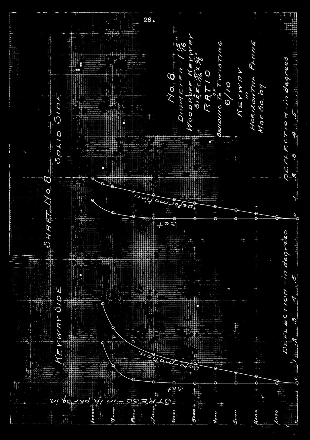
9 1. CONTENTS. Page. Introduction.2. General Discussion of Tests and Test Pieces Description of Apparatus 6. Method of Procedure 8. Formulae and Sample Calculations 10. Drawings and Photos 12. Tables 17. Sample Data 24. Curves 26. Conclusions ^2.
10


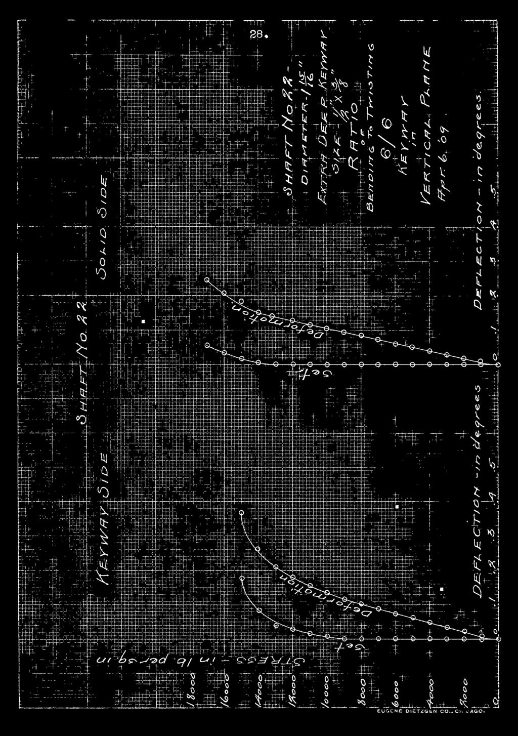
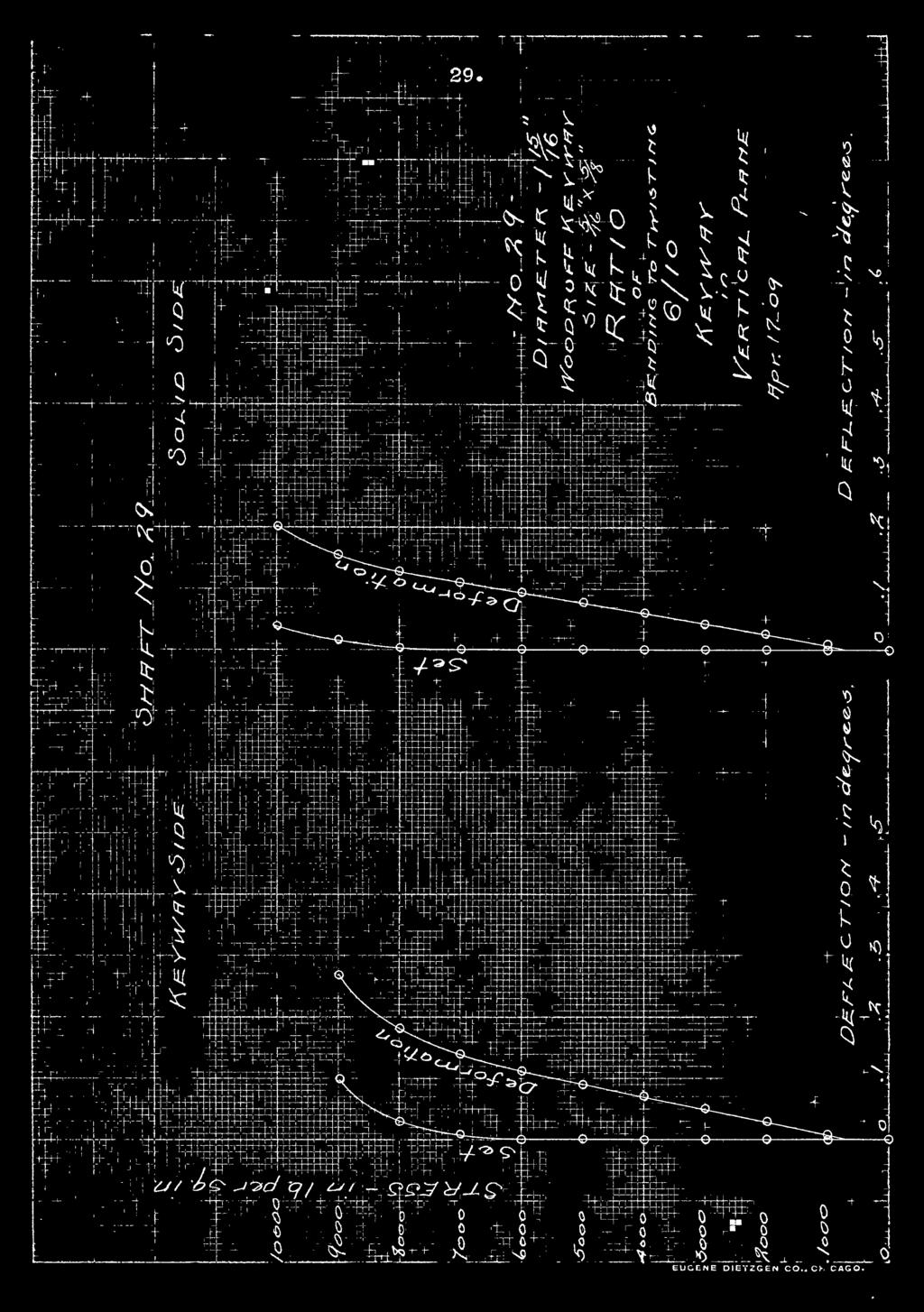
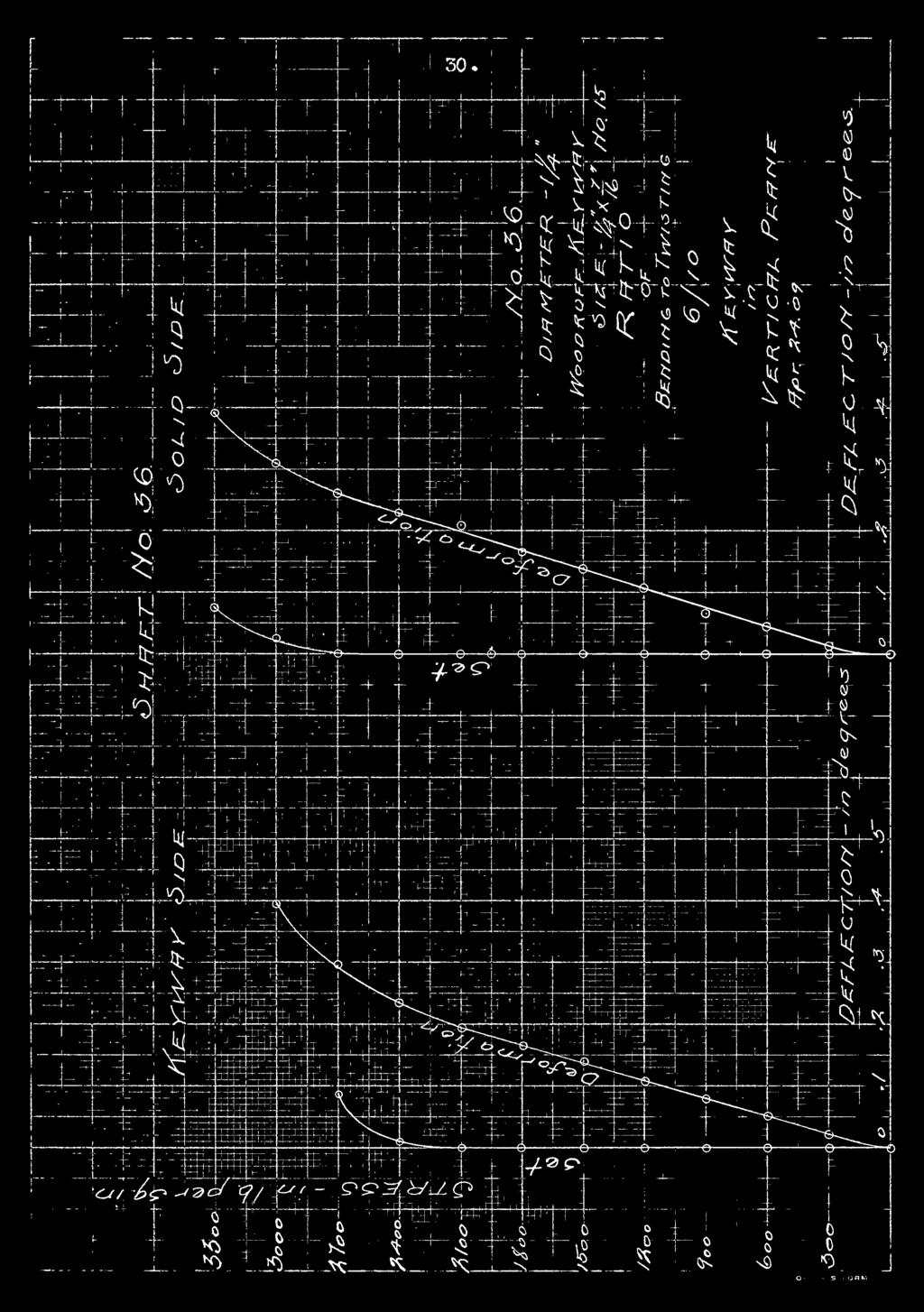
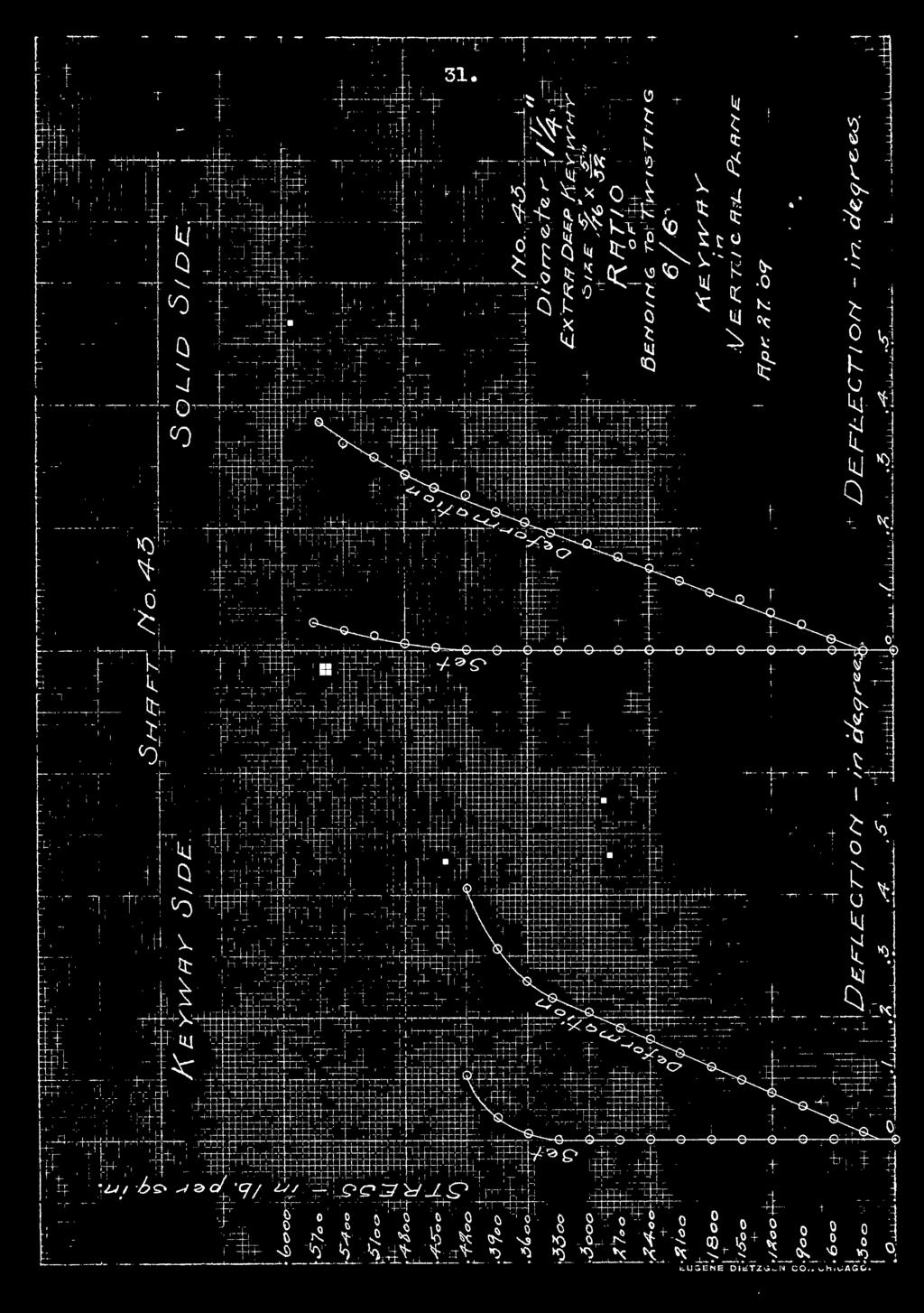
11 2. Introduction * There has been very little done on the subject of the "Effect of Keyways on the Strength of Shafts'*. Mr. Leidendecker of the Glass of 1908 of the University of Illinois, performed a series of tests on shafts, the tests being in simple torsion alone, and taking no account of the bending effect that comes on the shaft. His work is embodied in his graduating thesis. In the series of tests described in this thesis, combined torsion and bending were applied to the shafts tested. It is of some importance to a designer to know the effect of keyways on the strength of shafts, so that he may allow for the loss of strength thus incurred, in the designing of shafts met with, in machine construction. The tests included tests on shafts with four kinds of keyways; "standard", Extra wide. Extra Deep and keyways to take Woodruff keys. Two sizes of shafts, 1 15/16 inches, and 1 l/4 inches in diameter, were tested in duplicate with above in both combined twisting and bending. Two ratio of bending to twisting were used, one, with a ratio of 6/6 and the other, 6/10, In actual practice shafts are very frequently subjected to a combined torsion and bending which stresses the shaft to a greater degree than if subjected to simple torsion. This may be illustrated by a pulley midway between bearings on a cotint er- shaft, driving a machine below. That is the reason that these tests were made, and that the

12


13 I 3, relative amount of twisting moments applied, were varied during the series of tests. According to modem practice, there are two methods commonly used for fastening pulleys to shafts^by set screws and by keys. The set screw is convenient where the power to be transmitted is small but otherwise the use of keys is far more satisfactory. There are several ways in which keys are used. In some cases they are put in merely for the purpose of keeping the pulley from rotating on the shaft, thus driving by shearing action alone. In other cases the keys are used to prevent pulleys from sliding along the shaft as well as for the transmission of power. In the latter case they are machined all over so that they fit on all sides. This necessitates a taper and they must be driven in tightly, often eauses a severe bursting strain in the hufc of the pulley. But the fitting of taper keys is expensive so they are not used as much as the square keys, which are made to bear tightly on tv/o sides with a slight clearance on the top and bottom. Where shafts are made for sliding bearings as in the case of Drilling Machine Spindles, the depth of the keyway is generally made greater than in cases in which the pulley does not slide and when there is a heavy twisting moment to be transmitted, two keys are sometimes placed at right angles to each on the shaft. During later years the V/oodruff key has come into prominence and for many purposes is eminently satisfactory. These keys shown on page 12 Fig. 4. But it has some disadvantages, one of 1^ I

14

15 4. which is the great amount of trouble required to remove a key after it has once been fitted into place.
16


17 General Discussion of Tests and T_est Pieces, In the series of tests performed, a standard was assumed. This was done, because different Manufacturers use different standards and it was thought best to assume a keyway, fairly well averaging the dimensions of the different standards. The keyway assumed as a standard was based on the general formula; l/4 d in breadth, by 1/8 d in depth, in which "d" represents the diameter of the shaft. This would provide for a square key, the dimensions, of which, would be one-fourth of the diameter of the shaft. The sizes of the Woodruff keyways were selected by computing the twisting force at the s\irface of the shaft for thie maximum loads, and selecting Woodruff keys which were strong enough in shear to resist this force. The keys were selected by dividing the twisting force at the surface of the shaft by the allowable unit shearing stress of the material of which Woodruff keys are made, and choosing keys, v^hose cross-sectional area at the surface of the shafts equaled those quotients. The general appearance of Woodruff keyways is shown in the drawings page 12 Fig. 4 The different variations of tests were as follows 1. Shafts having a diameter of 1 15/16 inche. keyways in horizontal plane, ratio of twisting to bending 10 to Shafts having a diameter of 1 15/16 inch, keyways in horizontal plane, ratio of twisting to bonding 6 to 6.
18


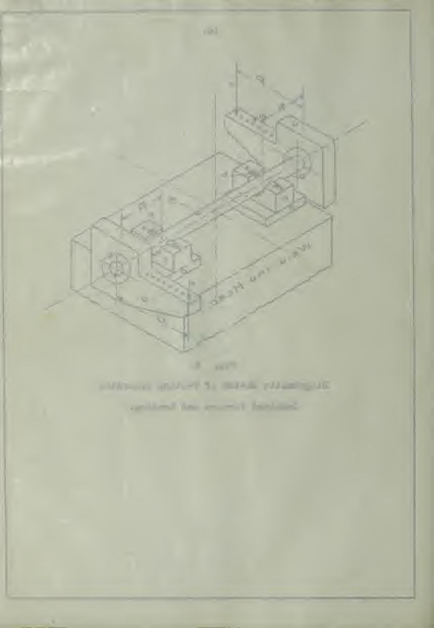
19 6. 3. Shafts having a diameter of 1 15/16 inch, keyways in vertical plane, ratio of twisting to bending 10 to 6, 4. Shafts having a diameter of 1 15/16 inch, keyways in vertical plane, ratio of twisting to bending 6 to 6, 5. Shafts having a diameter of 1 l/4 inch, keyways in vertical plane, ratio of twisting to bending 10 to Shafts having a diameter of 1 1/4 inch, keyways in vertical plane, ratio of twisting to bending 6 to 6, All variations of keyways used in each of the six series. All test ii made in duplicate. All shafts 30 inches in length. Description of App aratu s. The machine used in all the combined stress tests was the Philadelphia, 100,000 pounds capacity, in the Laboratory of Applied Mechanics at the University of Illinois. A special apparatus designed and built in the laboratory was attached to this machine which made it possible to secure combined stress. Such an apparatus is shown on page 15,and diagramatically on page 14. The shaft with keyways in the ends, is keyed to the rocker arm "a" as shown. The apparatus is then rested in bearings "b" which are supported by steel ball bearings in a race in the block "c". These blocks in turn are placed on plates "d" which are supported by two small I beams which rest on the weighing head of the testing machine. The blocks "c" with plates **d" are movable so as to vary the bending moment for the different ratios of

20


21 bending to twisting. The twisting moment is varied by shifting the tension! rods **e" along the rocker arms "a". These arms have spherical recesses *m" which give different arm lengths into which the spherical pointed projections on the tension rods fit. All other parts are rigidly fixed. Over the ends of the rocker arms "a" are hung the tension rods "e" Y/hich at their lower ends support an I Beam "f** fastened to the movable head "g" of the machine. In measuring the twist deflections indicators "h" were arrange[l as shown in the photograph Pig. 10 These indicators were specially designed for this particular series of tests performed in this thesis. They consisted of three long arms clamped on to the shaft and equally spaced along the shaft. One arm v/as clamped at the center, and the other two at equal distances as to span with the center arm, the part of the shaft including the keyway and a solid part, respectively. At the extreme end of the last two arms mentioned were placed scales glued ^to mirrors. The center arm held pointers, that these scales passed under as the shaft twisted* Readings were taken fron the scale in fiftieths of an inch and by reading the instrument when the pointer covered its own reflection, errors due to paralla? were avoided. The approximate length of the indicator arms necessary, was computed from the degrees twist, that was expected; and the distance between arms which was 5.5 inches. When the testing of the 1 l/4 inch shafts was begun, it was noticed that the machine was too inaccurate for close work, the

22


23 8» balance beam being too sluggish for the,* applied load, A needle beam was attached to the machine, immediately above the regular beam. This proved to be very satisfactory and the sensitiveness of the machine was such that the load on the specimen could be determined to within 10 pound load. Load was applied in increments of 1000 pounds, for the 1 15/l(i inch shaft and of 300 pounds for the 11/4 inch shafts. After readings were taken the load was taken off, until the initial load was reached. This gave a means of determining whether there had occurred any set or deformation in the shaft. This was continued until a set was obtained. Prom the readings so taken, we were able to plot curves showing relation between the stress applied and the set and the deformation suffered by the shaft, for both keyway and solid side of each shaft. All data taken during the test were recorded in a log book which is on file at the Research Office of the Laboratory of Appliedl Mechanics. A sample of notes taken is shown on page 24, also the calculated value as computed and used in working up results. Method of Procedure. 1i\e test pieces used 30 inches long and of two different sizes in diameter, 1 15/16 inches and 1 1/4 inches. In the series of tests, the ratio of bending to twisting was 6 to 10. At first, some of these shafts were tested with the keyv/ay in a horizontal plane, but owing to the fact that the neutral axis was in the same

24


25 j 9. plane, the keyway was not subjected to the maximum bending stress so that the later tests were all made with the keyway s in the vertical plane. When the apparatus was rigged up a load of 500 pounds was applied and was regarded as the initial or zero reading. The initial reading on the keyway side and on the solid side were noted, and the deflectometer "M** placed under the center of the shaft, its dial hand pointing to zero. The deflectometer readings gave approw imately the amount of bending. The shafts were tested in such a manner as to get the points i of set. In order to do this, an initial load was taken, and each time, after the load increment was added, the machine was reversed and the load brought to the initial load. In this manner a series of points were obtained. As long as the readings of twist were the same at the initial load, there was no set in the shaft, but when the readings began to increase at the initial load, the shaft was beginning to take a set. The point at which a set first took place is called " The point of first set", and this point would correspond to a given load. The load corresponding to the point of first set in the load, up to which, the shaft may be stressed, without causing it to take a set, that is it locates approximately the elastic limit. The material in the different shafts used, was not uniform, but that fact was judged to not effect, seriously, the results, as the strength of one shaft was not compared to that of another but rather the strength of a portion of a shaft, containing a

26


27 10. keyway, was compared to that of a portion of the same shaft, which did not contain a keyway. Preliminary calculations were reduced to constants. Thus, in mailing calculations for the degrees twist; knowing the length of the indicator arm, the distance the indicator arms were apart on the shafts, and the length of the spaces in inches, on the scale, a constant was found, which, when multiplied by the scale readings, gave the degrees twist per inch of shaft. Similarly a constant was found, knowing the length of the twisting arm and the size of the shaft, which, when mulitiplied by the load, gave the unit stres in the metal. Formulae and Sample Calculations. ( a ) = P-T = SJ. which 2 c M = Twisting moment in pound-inches. P = Load on scales. T = Length of twisting arm in inches. S = Unit stress in metal. J = Polar moment of inertia of shaft, c = Distance from neutral axis to extreme fiber or, in this case, the radius of the shaft. Substituting in the preceding formula for case of shaft 1 15/16 inches in diameter, ratio of bending to twisting 6 to 10. ^ ^ ^ - ^ ^ T0688 * S P
28


29 11. ( b ) Derivation of constants for degrees twist per inch. - L -0- = \ -, m which Li -9- = Angle of twist in radians. A = Scale readings in spaces. L = Distance from center of shaft to scale. Substituting for case of shaft 1 15/16 inches in diameter. L = inches. = radians. 37!375 X 5.5 ' 5.5 indicates the distance apart in inches the indicators were set on the shafts. 50 divisions on scale = 1 inch. in degrees per inch = ^ of length, of shaft = A.
30


31 12. Pig Diam. of Shaft, 1 inches. Woodruff Keyway No. S, 5/l6 in. x 5/8 in.
32


33 13 Fig. 7. Diam. Shaft, 1 ^ inches. Extra V7ide Keyway, in* x in. 8 Pig. 8. Diam. Shaft, 1 t inches. 1 7 Woodruff Keyway No. 15, ^ inch, x ^ inches.

34 V


35 14. Pig, 9. Diagramatic Sketch of Testing Apparatus Combined Torsion and Bending.
36


37 Fig, IC, Apparatus for Testing Shafts in Combined Torsion and Bending,
38


39 16, Figa 11* Shafts after having been Tested in Combined Torsion mid Bending*

40


41 17 Table No. 1. Diameter of Shaft = 1 i& inches. Horizontal Plane. Ratio = rr Dimensions of Keyway i x i 2 4 inches. Standard Extra Wide Extra Deep V/oodruff X i 4 1 x No. S. Stress at point of 1 first Set lb. per sq. 2 in. Keyway Side Stress at point of first Set lb. in. Solid Side. 1 per sq Loss of Strength Percent Average loss of Strength, Percent.

42


43 18. Table No Diameter of Shaft = 1 TB" inches. Horizontal Plane. Ratio = g. Standard Extra Wide Extra Deep Woodruff Dimensions of Keywayinches. 1 X X 1 1 X No. S. Stress at point of 1 first Set lb. per sq. 2 in. Keyway Side Stress at point of 1 first Set lb. per sq. 2 in. Solid Side Loss of Strength Percent Average loss of Strength, Percent.
44


45 19. 1 laole wo. L>iainst.er oi onait J. inches. Vertical Plane. Ratio = ot* anclara Extra Wide Extra Deep V/oodruff Dimensions of Key ways inches* X No. S. Stress at point of first Set lb. per sq. m. xveyway oicie. Stress at point of first Set lb. per sq. m. Solid Side f57no O P750 JjOSS 01 otrengtn Percent Average loss of olreng ^n Percent.

46


47 20. Table No Diameter of Shaft = 1 "Jg inches. Vertical Plane. Ratio = g Standard Extra Wide Extra Deep Woodruff Dimensions of P^eyways inches No. S Stress at point of first Set lb. per sq. in. Keyway Side P P Stress at point of first Set lb. per sq. in. Solid Side Loss of Strength Percent Average loss of Strength Percent.
48


49 21. Table No Diameter of Shaft = 1 t ir^ches. Vertical Plane. Ratio = Standard Extra Wide Extra Deep Woodruff Dimensions of Keyway inches. 5x x X N Stress at point of 1 first Set lb. per sq, 2 in. Keyway Side Stress at point of 1 first Set lb. per sq. 2 in. Solid Side Loss of Strength Percent Average loss of Strength Percent.
50


51 22. Table No. 6. Diameter of Shaft = 1 ^ inches. Vertical Plane. Ratio =. Standard Extra Wide Kxtra Deep Woodruff Dimensions of Keyway inches X 5 5 ^ No. 15 Stress at point of first Set lb. per sq. in. Keyway Side Stress at point of first Set lb. per sq. in. Solid Side Loss of Strength Percent Average loss of Strength Percent.
52


53 23. Table NO. 7. General Averages of Loss of Strength. ( in percent ) Standard Keyway Double Width " ^ Stranded Depth " 26. Woodruff * 14.8 Table No. 8. Loss of Strength in Percent. Standard Key ways. Combined Stresses. Simple Torsion. Size of Shaft Ratio of Ratio of 6 to 10 6 to 6 ^ Yq inches. ( Leidendecker ) Size of Shaft 1 i inches

54


55 24. Sample Data Shaft No. 6 Load A B C Unit Stress Twist Degrees per lb* lb. per sq.iq. incvi > A B

56
 B. - Right hand scale -( Solid shaft ) C.")
57 Sample Data. ( continued ) Duplicate Extra Wide Length 30 inches Diameter 1 15/16 inches Size of Keyway 1 in. x l/4 in. Twisting Arm 10 inches Bending Arm 6 inches. Ratio A. - Left hand scale - ( Keyway ) B. - Right hand scale -( Solid shaft ) C. - Deflectometer - ( Center of shaft ) KeywEy set in Horizontal Plame.

58


59

60


61 EUGENE DIETZCEN CO.. CHICAGO.

62

63
64


65

66


67

68

69

70


71 ' 32. Conclusions,! The first set, in almost every case, took place under the load corresponding to the yield point. 2. The shafts were materially weakened by having the keyways in the vertical plane rather than in the horizontal plane. When in the vertical position the keyway was in that part of the shaft subjected to the greatest stress due to bending, but when it was in the horizontal position it was practically in the neutral axis. 3. There was considerable loss in stiffness as indicated in the following table. The table gives the loss of stiffness in percent. Ratio of Twisting 1 inch. Diam. 1^ inch. Diam. to Bending 10 to to In general the keyway s had a weakening effect in the following order J- Extra wide 29 percent. Extra deep 26 " " Woodruff 14.8 " " Standard The extra wide keyv;ays had the greatest weakening effect, due th the fact that the most metal was removed from the part of
72


73 33. the shaft that was subjected to the greatest torsional stress. Contrary to general opinion, the V/oodruff keyways, next to the standard keyways, showed the least weakening effect, because in cutting a Woodruff keyway, more metal is taken from nearer the axis of the shaft, and not so much from the outer fibres, which are undei' the greatest torsional stress. 5. In comparing the results of this series of tests with those obtained by Mr. P. E. Leidendecker, of the Glass of 1908 of the University of Illinois, in a series of tests in torsion alone, it is plainly shown that a keyway has a greater weakening effect if the shaft is subjected to both torsion and bending. 6. It would be well, when selecting a shaft, to make allowance for the weakening effect of keyways. This could be done by assuming a working stress of 15 percent or 20 percent lower than that used in usual calculations.

74

75


76
TEST FOR STABILOMETER VALUE OF BITUMINOUS MIXTURES
 Test Procedure for TEST FOR STABILOMETER VALUE OF BITUMINOUS MIXTURES TxDOT Designation: Tex-208-F Effective Date: February 2005 1. SCOPE 1.1 Use this test method to determine the Hveem stability value
METROLOGY LAB. I DEVICES BASED ON VERNIER SCALE
 METROLOGY LAB. I DEVICES BASED ON VERNIER SCALE Indirect Measurement; two balls 2 Lab6: Roundness Test 12/1/2017 Indirect Measurement; four balls 3 Lab6: Roundness Test 12/1/2017 Angle measurement using
A Low Cost Digital Angle Gage, version 3
 A Low Cost Digital Angle Gage, version 3 By R. G. Sparber Copyleft protects this document. 1 Sometimes re-inventing the wheel has advantages. What you see here is just a variation on a sine bar. The accuracy
Certified Accuracy. Ring Force Gauge. Models and Capacities Available. Design and Principle of Operation
 Certified Accuracy Ring Force Gauge The accurate measurement of mechanical forces is required in hundreds of applications from a simple weighing procedure to the calibration of testing machines and load
CHAIN DRIVE Introduction Merits and demerits of chain drives Merits Demerits
 70 CHAIN DRIVE Introduction Chain is used to transmit motion from one shaft to another shaft with the help of sprockets. Chain drives maintain a positive speed ratio between driving and driven components,
EEF. Fatigue Testing Unit PROCESS DIAGRAM AND UNIT ELEMENTS ALLOCATION. Engineering and Technical Teaching Equipment
 Engineering and Technical Teaching Equipment Fatigue Testing Unit EEF PROCESS DIAGRAM AND UNIT ELEMENTS ALLOCATION ISO 9001: Quality Management (for Design, Manufacturing, Commercialization and After-sales
for Cold-Formed Steel Framing Products
 Technical Guide for Cold-Formed Steel Framing Products Technical Data in this publication is applicable to the following SFIA Member Company: For a complete directory of SFIA Members who are certified
for Cold-Formed Steel Framing Products
 Technical Guide for Cold-Formed Steel Framing Products The data in this guide is based upon the 2007 American Iron and Steel Institute s S00-07 North American Specification for the Design of Cold-Formed
Western Lumber SPAN TABLES. Western Wood Products Association. for Floor and Ceiling Joists and Roof Rafters. computed with
 Western Wood Products Association computed with BASE VALUES for dimension lumber Western Lumber SPAN TABLES for Floor and Ceiling Joists and Roof Rafters TABLE OF CONTENTS About WWPA.......................................
Sprocket Selection Guidelines
 Sprocket Selection Guidelines Table 1 Information Necessary to Order Sprockets 1. Chain Size Number, type, or drawing number of the chain to be used on the sprocket. (The suitability of a sprocket depends
Engineering Practice on Ice Propeller Strength Assessment Based on IACS Polar Ice Rule URI3
 10th International Symposium on Practical Design of Ships and Other Floating Structures Houston, Texas, United States of America 2007 American Bureau of Shipping Engineering Practice on Ice Propeller Strength
OPENINGS AND REINFORCEMENTS 26
 ASME BPVC.VIII.1-2015 UG-35.2 UG-36 (4) It is recognized that it is impractical to write requirements to cover the multiplicity of devices used for quick access, or to prevent negligent operation or the
G238. G238 Family 3 & 4 Point Bend Fixtures Modular & Configurable. Features
 G238 G238 Family 3 & 4 Point Bend Fixtures Modular & Configurable The G238 features a unique modular design enabling it to expand to a variety of test scenarios from a standard 3 point bend test to 4 point
Product Identification
 Product Identification All SCAFCO products have a four part identification code which identifies the size (both depth and flange width), style, and material thickness of each member. Example: Member Depth:
DX2/DXX Operating Instructions
 CHECK LINE BY ELECTROMATIC DX2/DXX Operating Instructions CHECK LINE INSTRUMENTS ELECTROMATIC E Q U I P M E N T C O., I N C. 600 Oakland Ave., Cedarhurst, NY 11516 U.S.A. TEL: 516-295-4300 FAX: 516-295-4399
GEOL 106: Earthquake Country Activity 08: Discharge Measurements. Name: Date:
 Name: Date: Discharge Calculation Discharge = Velocity X Area or Q = VA Calculate the Discharge for the measurements shown at the right. Q = Discharge Measurement Do not collect water samples in the area
Unit for Determining the Gauge Factor of Strain Gauges
 Engineering and Technical Teaching Equipment Unit for Determining the Gauge Factor of Strain Gauges MFGE PROCESS DIAGRAM AND UNIT ELEMENTS ALLOCATION ISO 9001: Quality Management (for Design, Manufacturing,
INTRODUCTION TABLE OF CONTENTS
 2 INTRODUCTION Thank you for choosing Servometer to design and manufacture your unique, new electrodeposited bellows for your particular application. The definitions, formulas and design parameters inside
INTRODUCTION. Disclaimer
 3 INTRODUCTION The Steel Framing Industry Association (SFIA) was formed with the objective of assisting companies having interests in the cold-formed steel framing industry to be more successful by unifying
915 MEASUREMENT OF STRUCTURAL STRENGTH OF SEMISOLIDS BY PENETROMETRY
 BRIEFING 915 Measurement of Structural Strength of Semisolids by Penetrometry. This proposed chapter describes empirical methods of measuring the structural strength or consistency of a semisolid raw material
L-header Testing, Evaluation and Design Methodology
 Missouri University of Science and Technology Scholars' Mine International Specialty Conference on Cold- Formed Steel Structures (2000) - 15th International Specialty Conference on Cold-Formed Steel Structures
Scissor Mechanisms. Figure 1 Torero Cabin Service Truck. Scissor Mechanism was chassis mounted and lifted the cabin to service aircraft
 Scissor Mechanisms Scissor mechanisms are very common for lifting and stabilizing platforms. A variety of manlifts, service platforms and cargo lifts utilize this visually simple but structurally complex
GERMAN ENGINEERED INNOVATIONS
 GERMAN ENGINEERED INNOVATIONS D E S I G N E D B Y W E R N E R N I C K E L DESIGN CONSTRUCTION This face balanced putter design offers two lateral stainless steel counterweights that extend from the back
OP CHECKLIST FOR 1D CONSOLIDATION LABORATORY TEST
 Page 1 of 5 WORK INSTRUCTIONS FOR ENGINEERS NHB Compiled by : LSS Checked by : GSS Approved by : OP-3-31. CHECKLIST FOR 1D CONSOLIDATION LABORATORY TEST Page 2 of 5 31.0 CHECKLIST ITEMS *(refer to respective
Other Si min/max. Cr min/max. 0.4/ / / / Bal.
 178.46 Specification 3AL seamless aluminum cylinders. (a) Size and service pressure. A DOT 3AL cylinder is a seamless aluminum cylinder with a imum water capacity of 1000 pounds and minimum service pressure
Copyright ASTM International, 100 Barr Harbor Drive, PO Box C700, West Conshohocken, PA , United States.
 LastD 4429 93 standard and is intended only to provide the user of an ASTM standard an indication of what changes have been made to the previous version. Because it may not be technically possible to adequately
Modeling of Hydraulic Hose Paths
 Mechanical Engineering Conference Presentations, Papers, and Proceedings Mechanical Engineering 9-2002 Modeling of Hydraulic Hose Paths Kurt A. Chipperfield Iowa State University Judy M. Vance Iowa State
- a set of known masses, - four weight hangers, - tape - a fulcrum upon which the meter stick can be mounted and pivoted - string - stopwatch
 1. In the laboratory, you are asked to determine the mass of a meter stick without using a scale of any kind. In addition to the meter stick, you may use any or all of the following equipment: - a set
SERIES A24 RAISED RIB
 SERIES A24 RAISED RIB Eurobelt Series A24 Raised Rib conveyor belt has been designed mainly to be used with finger plates. It has ribs that, sticking out 6 mm above the module, provide a greater resistance
Tex-414-A, Air Content of Freshly Mixed Concrete by the Volumetric Method
 by the Volumetric Method Contents: Section 1 Overview...2 Section 2 Apparatus...3 Section 3 Sampling Requirements...5 Section 4 Procedures...6 Section 5 Calculation...9 Section 6 Archived Versions...10
Analysis of dilatometer test in calibration chamber
 Analysis of dilatometer test in calibration chamber Lech Bałachowski Gdańsk University of Technology, Poland Keywords: calibration chamber, DMT, quartz sand, FEM ABSTRACT: Because DMT in calibration test
Hatch cover securing and tightness
 (1986) (Rev 1 1996) (Corr.1 June 2000) (Rev.2 July 2005) (Corr.1 Oct 2005) Hatch cover securing and tightness 1. Application 1.1 The following recommendations apply to steel hatch covers that are fitted
Stress evaluation of a bicycle crank arm connection using BEM
 Stress evaluation of a bicycle crank arm connection using BEM C. J. Hoff, R. E. Dippery & 3. Knapp Department of Mechanical Engineering Kettering University, USA Abstract An interesting problem encountered
Now with SUPREME FRAMING SYSTEM! PRODUCT TECHNICAL GUIDE. Steel Stud Manufacturers Association
 Now with SUPREME FRAMING SYSTEM! PRODUCT TECHNICAL GUIDE Steel Stud Manufacturers Association 2507 3064P Product Identification "S" and "SFS" - C-STUD/JOIST S and SFS-SECTIONS* * For "S" and "SFS" members,
(fig. 3) must be at the same temperature as the water in this chamber CALORIMETRIC STUDIES OF THE EXTREMITIES
 must be at the same temperature as the water in this chamber CALORIMETRIC STUDIES OF THE EXTREMITIES") CALORIMETRIC STUDIES OF THE EXTREMITIES II. EXPERIMENTAL APPARATUS AND PROCEDURES' By ROY KEGERREIS (Received for publication July 1, 1926) The calorimeter used in these experiments is a modification of
CALORIMETRIC STUDIES OF THE EXTREMITIES II. EXPERIMENTAL APPARATUS AND PROCEDURES' By ROY KEGERREIS (Received for publication July 1, 1926) The calorimeter used in these experiments is a modification of
COURSE NUMBER: ME 321 Fluid Mechanics I Fluid statics. Course teacher Dr. M. Mahbubur Razzaque Professor Department of Mechanical Engineering BUET
 COURSE NUMBER: ME 321 Fluid Mechanics I Fluid statics Course teacher Dr. M. Mahbubur Razzaque Professor Department of Mechanical Engineering BUET 1 Fluid statics Fluid statics is the study of fluids in
(12) Patent Application Publication (10) Pub. No.: US 2012/ A1
 Patent Application Publication (10) Pub. No.: US 2012/ A1") (19) United States US 201201 00965A1 (12) Patent Application Publication (10) Pub. No.: US 2012/0100965 A1 Dreissigacker et al. (43) Pub. Date: Apr. 26, 2012 (54) EXERCISING (52) U.S. Cl.... 482/72 (76)
(19) United States US 201201 00965A1 (12) Patent Application Publication (10) Pub. No.: US 2012/0100965 A1 Dreissigacker et al. (43) Pub. Date: Apr. 26, 2012 (54) EXERCISING (52) U.S. Cl.... 482/72 (76)
Rig Math. Page 1.
 Page 1 The Calculator and Main Keyboard Display Numerical 10-key pad used for entering numerical values Trigonometric Functions These keys will be used where wellbore angle is an issue These are the keys
Rules for the Installation, Inspection and Testing of Air Reservoirs (Other than on Locomotives)
") Rules for the Installation, Inspection and Testing of Air Reservoirs (Other than on Locomotives) December 5, 1994 TM Rules for the Installation, Inspection and Testing of Air Reservoirs (Other than on
Rules for the Installation, Inspection and Testing of Air Reservoirs (Other than on Locomotives) December 5, 1994 TM Rules for the Installation, Inspection and Testing of Air Reservoirs (Other than on
Irrigation &Hydraulics Department lb / ft to kg/lit.
 CAIRO UNIVERSITY FLUID MECHANICS Faculty of Engineering nd Year CIVIL ENG. Irrigation &Hydraulics Department 010-011 1. FLUID PROPERTIES 1. Identify the dimensions and units for the following engineering
MODEL WEIGH MODULE
 MODEL 65082 WEIGH MODULE INSTALLATION & OPERATING MANUAL P.O. Box 775 - Farmington, NH 03835 Tel: 603-755-3885 email: cands_nh@msn.com www.candscontrols.com Model 65023 Cantilever Beam Transducer Nickel-Plated
AIRMOUNT VIBRATION ISOLATION
 MOUNT VIBRATION ISOLATION SELECTION AND ISOLATION FORMULA Refer to the selection guide on page 33 for Airmount load and isolation capabilities. Follow this procedure: 1. LOAD CAPACITY Select one or two
Design and Analysis of Rotary Lawn Mower
 Design and Analysis of Rotary Lawn Mower Vivek P Revi Vishnu N V Akhil K A Rohith P Kevin Rozario Abstract- KAMCO Industries, Athani, India is a reputed industry undertaken by Kerala state government producing
(Received 9 September 1940)
") 257 J. Physiol. (I 94I) 99, 257-264 6I2.2II A METHOD OF RECORDING THE RESPIRATION BY J. H. GADDUM From the College of the Pharmaceutical Society, 17 Bloomsbury Square, London, W.C. 2 (Received 9 September
257 J. Physiol. (I 94I) 99, 257-264 6I2.2II A METHOD OF RECORDING THE RESPIRATION BY J. H. GADDUM From the College of the Pharmaceutical Society, 17 Bloomsbury Square, London, W.C. 2 (Received 9 September
V393.R46. NalupwL UNITED STATES EXPERIMENTAL MODEL BASIN NAVY YARD, WASHINGTON, D.C. BILGE KEEL CAVITATION J. G. THEWS SEPTEMBER REPORT NO.
 V393.R46 NalupwL 3 9080 02753 9680 UNITED STATES EXPERIMENTAL MODEL BASIN NAVY YARD, WASHINGTON, D.C. BILGE KEEL CAVITATION BY J. G. THEWS SEPTEMBER 1933 REPORT NO. 371 MWIF- _ BILGE KEEL CAVITATION By
tbs TDC8(5630)P 3 Draft Tanzania Standard Textiles Ropes Specifications: Part 2. Ropes made from Man-made fibres (First edition)
P 3 Draft Tanzania Standard Textiles Ropes Specifications: Part 2. Ropes made from Man-made fibres (First edition)") tbs TDC8(5630)P 3 Draft Tanzania Standard Textiles Ropes Specifications: Part 2. Ropes made from Man-made fibres (First edition) TANZANIA BUREAU OF STANDARDS 0. FOREWORD 0.1 The range of man-made fibre
tbs TDC8(5630)P 3 Draft Tanzania Standard Textiles Ropes Specifications: Part 2. Ropes made from Man-made fibres (First edition) TANZANIA BUREAU OF STANDARDS 0. FOREWORD 0.1 The range of man-made fibre
Torsional rigidity of structural sections, Civil Engineering, Vol. 5, (1935), p. 698
, p. 698") Lehigh University Lehigh Preserve Fritz Laboratory Reports Civil and Environmental Engineering 1935 Torsional rigidity of structural sections, Civil Engineering, Vol. 5, (1935), p. 698 B. G. Johnston Follow
Lehigh University Lehigh Preserve Fritz Laboratory Reports Civil and Environmental Engineering 1935 Torsional rigidity of structural sections, Civil Engineering, Vol. 5, (1935), p. 698 B. G. Johnston Follow
Hoisting Equipment Cable puller & Accessories
 Yale hoists and trolleys are not ed for Cable puller model Yaletrac Pulling force 800-3200 It has a light weight, compact, high tensile aluminium alloy housing with a large flat bottom surface for increased
CEILING JOISTS ROOF RAFTERS
 TABLE OF CONTENTS About WWPA......................................... 3 Groupings..................................... 3 Design Values........................................ 3 Mechanical Properties..................................
σ = force / surface area force act upon In the image above, the surface area would be (Face height) * (Face width).
 * (Face width).") Aortic Root Inflation Introduction You have already learned about the mechanical properties of materials in the cantilever beam experiment. In that experiment you used bending forces to determine the Young
Aortic Root Inflation Introduction You have already learned about the mechanical properties of materials in the cantilever beam experiment. In that experiment you used bending forces to determine the Young
Chain Drives. Chain Drives 759 C H A P T E R
 Chain Drives 759 C H A P T E R 21 Chain Drives 1. Introduction. 2. Advantages and Disadvantages of Chain Drive over Belt or Rope Drive. 3. Terms Used in Chain Drive. 4. Relation Between Pitch and Pitch
Everything you need to know about flatteners and levelers for coil processing
 http://www.thefabricator.com/xp/fabricator/articles/fabricating/fabricating03/02web56 9.xml Provided by: Welded Tube Pros LLC, www.weldedtubepros.com Doylestown, OH. Tel: 330-658-7070 Email contact for
Lifecycle Performance of Escape Systems
 Lifecycle Performance of Escape Systems A look at laboratory vs field conditioning of aramid fiber based escape systems. By James Hunter, Cedric Smith, Ole Kils and Tyler Mayer for ITRS 2018 1.1 Introduction
Davorin Matanović DRILLING LINE (ROPE) AND BLOCKS
 AND BLOCKS") Davorin Matanović DRILLING LINE (ROPE) AND BLOCKS DRILLING LINE (ROPE) AND BLOCKS The term drilling line pertain to the wire rope made from steel wires. It is spooled onto the drum of the draw works hoist,
Davorin Matanović DRILLING LINE (ROPE) AND BLOCKS DRILLING LINE (ROPE) AND BLOCKS The term drilling line pertain to the wire rope made from steel wires. It is spooled onto the drum of the draw works hoist,
Lab 7 Rotational Equilibrium - Torques
 Lab 7 Rotational Equilibrium - Torques Objective: < To test the hypothesis that a body in rotational equilibrium is subject to a net zero torque and to determine the typical tension force that the biceps
SERIES E30 RAISED RIB
 SERIES E30 RAISED RIB Eurobelt Series E30 Raised Rib conveyor belt has been designed mainly for making product transfers by using finger plates. Due to its smooth surface of projecting ribs, it is recommended
Mini Channel & Fittings
 Our mini channels and fittings provide for an economical method of supporting light load requirements on a strut system. Channel Channels are cold formed on our modern rolling mills from 18 Ga. (1.2 mm)
Alternative Methods For Making CoCoRaHS Snow Water Content Measurements. Prepared by: Rick Fleetwood Environment Canada Updated Feb 2015
 Alternative Methods For Making CoCoRaHS Snow Water Content Measurements Prepared by: Rick Fleetwood Environment Canada Updated Feb 2015 Introduction This document will cover off two alternate methods for
The Mechanics of Friction in Rope Rescue
 The Mechanics of Friction in Rope Rescue Stephen W. Attaway, Ph.D. attaway@highfiber.com International Technical Rescue Symposium (ITRS 99) Frictional forces play an important role in rope rescue. Friction
LAB 7. ROTATION. 7.1 Problem. 7.2 Equipment. 7.3 Activities
 LAB 7. ROTATION 7.1 Problem How are quantities of rotational motion defined? What sort of influence changes an object s rotation? How do the quantities of rotational motion operate? 7.2 Equipment plumb
Chain Drives. 1. As no slip takes place during chain drive, hence perfect velocity ratio is obtained
 1. Introduction Chain Drives In Belt and Rope drives slipping may occur. In order to avoid slipping, steel chains are used. The chains are made up of a number of rigid links which are hinged together by
Serving. Petrochemicals Power Semiconductor Waste Treatment Oil & Gas Transmission Lines Bulk Gas Plants
 Serving Petrochemicals Power Semiconductor Waste Treatment Oil & Gas Transmission Lines ulk Gas Plants Mining & Metals Pharmaceuticals Pulp & Paper Mills Sugar Mills Nuclear Desalinization Plants NOTES:
S0300-A6-MAN-010 CHAPTER 2 STABILITY
 CHAPTER 2 STABILITY 2-1 INTRODUCTION This chapter discusses the stability of intact ships and how basic stability calculations are made. Definitions of the state of equilibrium and the quality of stability
machine design, Vol.6(2014) No.3, ISSN pp
 No.3, ISSN pp") machine design, Vol.6(04) No.3, ISSN 8-59 pp. 79-84 ANALYSIS OF CLEARANCES AND DEFORMATIONS AT CYCLOID DISC Mirko BLAGOJEVIĆ * University of Kragujevac, Faculty of Engineering, Kragujevac, Serbia Preliminary
machine design, Vol.6(04) No.3, ISSN 8-59 pp. 79-84 ANALYSIS OF CLEARANCES AND DEFORMATIONS AT CYCLOID DISC Mirko BLAGOJEVIĆ * University of Kragujevac, Faculty of Engineering, Kragujevac, Serbia Preliminary
Serving. Petrochemicals Power Semiconductor Waste Treatment Oil & Gas Transmission Lines Bulk Gas Plants
 Serving Petrochemicals Power Semiconductor Waste Treatment Oil & Gas Transmission Lines ulk Gas Plants Mining & Metals Pharmaceuticals Pulp & Paper Mills Sugar Mills Nuclear Desalinization Plants NOTES:
MAE 322 Machine Design Lecture 5 Fatigue - 2. Dr. Hodge Jenkins Mercer University
 MAE 322 Machine Design Lecture 5 Fatigue - 2 Dr. Hodge Jenkins Mercer University Returning to Stress-Life Fatigue Modeling Fatigue Stress-Life: S f -N Diagram for steels Stress levels below S e (Endurance
Prof. B V S Viswanadham, Department of Civil Engineering, IIT Bombay
 43 Module 3: Lecture - 5 on Compressibility and Consolidation Contents Stresses in soil from surface loads; Terzaghi s 1-D consolidation theory; Application in different boundary conditions; Ramp loading;
Equation 1: F spring = kx. Where F is the force of the spring, k is the spring constant and x is the displacement of the spring. Equation 2: F = mg
 1 Introduction Relationship between Spring Constant and Length of Bungee Cord In this experiment, we aimed to model the behavior of the bungee cord that will be used in the Bungee Challenge. Specifically,
River Bridge - Test Shaft-1 Clarke County, MS, 4/2/2012
 Page 1 of 9 The enclosed report contains the data and analysis summary for the SoniCaliper shaft caliper, performed at River Bridge (Test Shaft-1), Clarke County, MS on Monday, April 02, 2012 by Dave Jakstis.
Impact Test Equipment Ltd & User Guide. User Guide
 SL Impact Test Equipment Ltd www.impact-test.co.uk & www.impact-test.com User Guide User Guide Impact Test Equipment Ltd. Building 21 Stevenston Ind. Est. Stevenston Ayrshire KA20 3LR T: 01294 602626 F:
FOR MORE INFORMATION CONTACT OUR NEAREST BRANCH OFFICE
 1 SECTION 1 - Wire Rope WIRE ROPE General Information Terminology & Properties Terminology With precise, moving parts, designed and manufactured to bear definite relationship to one another, Wire Rope
Analysis of Shear Lag in Steel Angle Connectors
 University of New Hampshire University of New Hampshire Scholars' Repository Honors Theses and Capstones Student Scholarship Spring 2013 Analysis of Shear Lag in Steel Angle Connectors Benjamin Sawyer
WHEELING IN MARCHING, OR ON A MOVABLE PIVOT. At drill day we tried to reconcile the instructions for the maneuver for wheeling while being in motion.
 14 March 2012 WHEELING IN MARCHING, OR ON A MOVABLE PIVOT POC: Steve Giovannini, Don Miskey At drill day we tried to reconcile the instructions for the maneuver for wheeling while being in motion. 1. Right
STRESS ANALYSIS OF BICYCLE PADDLE AND OPTIMIZED BY FINITE ELEMENT METHOD. S. Abeygunasekara 1, T. M. M. Amarasekara 2
 - 96 - STRESS ANALYSIS OF BICYCLE PADDLE AND OPTIMIZED BY FINITE ELEMENT METHOD S. Abeygunasekara 1, T. M. M. Amarasekara 2 1 Faculty of Engineering & Technology, Colombo International Nautical Engineering
M CLASS RATING RULES
 M CLASS RATING RULES The following are the freesail M Class building rules, originally adopted by M.Y.R.A.A. (Model Yacht Racing Association of America) on April 14, 1932 and by I.M.Y.R.U (International
Vessel Weighing. Load Cells and Weigh Modules VPG TRANSDUCERS. Technical Note VPGT-06. Scope. Accuracy. Mode of Operation. Mechanical Considerations
 VPG TRANSDUCERS Load Cells and Weigh Modules Technical Note VPGT-06 Scope Load cells may be used to weigh vessels in various installation configurations. The installation of load cells into a practical
Fluid Machinery Introduction to the laboratory measurements
 Fluid Machinery Introduction to the laboratory measurements Csaba H s (csaba.hos@hds.bme.hu) Ferenc Hegedus (hegedusf@hds.bme.hu) February 21, 2014 1 Requirements related to the measurement part of the
Structural Design of Tank Weighing Systems
 Structural Design of Tank Weighing Systems 1. Initial observations Some essential rules must be followed when installing load cells in tanks. For example, tanks are frequently subject to weather conditions
5. STRUCTURAL ANALYSIS
 5. STRUCTURAL ANALYSIS The skeletal structure of the experiment casing is constructed from UNISTRUT with all experiment equipment mounted by UNISTRUT provided fasteners. All maximum loads for nuts, bolts,
Homework of chapter (3)
") The Islamic University of Gaza, Civil Engineering Department, Fluid mechanics-discussion, Instructor: Dr. Khalil M. Al Astal T.A: Eng. Hasan Almassri T.A: Eng. Mahmoud AlQazzaz First semester, 2013. Homework
The Islamic University of Gaza, Civil Engineering Department, Fluid mechanics-discussion, Instructor: Dr. Khalil M. Al Astal T.A: Eng. Hasan Almassri T.A: Eng. Mahmoud AlQazzaz First semester, 2013. Homework
SET OF EUROLEAGUE BACKSTOP UNITS (Reference PK120)
") SET OF EUROLEAGUE BACKSTOP UNITS (Reference PK120) DESCRIPTION The EUROLEAGUE backstop unit is mainly designed for multi-sports pavilions and installations where the highest-level basketball competitions
SET OF EUROLEAGUE BACKSTOP UNITS (Reference PK120) DESCRIPTION The EUROLEAGUE backstop unit is mainly designed for multi-sports pavilions and installations where the highest-level basketball competitions
Vessel Weighing. Load Cells VPG TRANSDUCERS. Application Note VPG-06 TECH NOTE. Scope. Accuracy. Mode of Operation. Mechanical Considerations
 VPG TRANSDUCERS Load Cells Application Note VPG-06 Scope Load cells may be used to weigh vessels in various installation configurations. The installation of load cells into a practical field application
3 1 PRESSURE. This is illustrated in Fig. 3 3.
 P = 3 psi 66 FLUID MECHANICS 150 pounds A feet = 50 in P = 6 psi P = s W 150 lbf n = = 50 in = 3 psi A feet FIGURE 3 1 The normal stress (or pressure ) on the feet of a chubby person is much greater than
AUSTRALIAN ARROW AND ARAFURA CADET ASSOCIATION ARROW CATAMARAN RESTRICTIONS AND MEASUREMENT CERTIFICATE
 AUSTRALIAN ARROW AND ARAFURA CADET ASSOCIATION ARROW CATAMARAN RESTRICTIONS AND MEASUREMENT CERTIFICATE 1 NOTE: The object of these restrictions is to provide uniform specifications and restrictions for
ENGINEERING DESIGN GUIDE. D-M-E Hydraulic Unscrewing Device
 ENGINEERING DESIGN GUIDE D-M-E Hydraulic Unscrewing Device ENGINEERING DESIGN GUIDE D-M-E Hydraulic Unscrewing Device Hydraulic Unscrewing Device Without guiding thread with cam Safety Considerations Mold
Concave and Flat Expander Anti-Wrinkle Rollers:
 Concave and Flat Expander Anti-Wrinkle Rollers: For Better or For Worse? Timothy J. Walker tjwalker@tjwa.com (651) 686-5400 Office (651) 249-1121 Mobile (866) 572-3139 Fax NEW WWW.TJWA.COM 164 Stonebridge
Wooden Canoe. Building a One-Off Wood & Canvas Canoe. Ray Arcand: A Living Link to the Past. Issue 134, April 2006 Volume 29, No.
 Wooden Canoe Issue 134, April 2006 Volume 29, No. 2 Building a One-Off Wood & Canvas Canoe Courses, Classes, Early Summer Ray Arcand: A Living Link to the Past WCHA Annual Report Building a One-Off Wood
E02 Rigid hinged stinger with piggyback line
 E02 Rigid hinged stinger with piggyback line This model represents a rigid stinger hinged off the back of a lay vessel using the pipelay supports feature. In addition to the lay pipe, another line is included
Multihull Preliminary Stability Estimates are Fairly Accurate
 Multihull Design (Rev. A) 45 APPENDIX A ADDITIONAL NOTES ON MULTIHULL DESIGN MULTIHULL STABILITY NOTES Multihull stability is calculated using exactly the same method as described in Westlawn book 106,
CONE PENETRATION TESTS
 February 25, 2015 John Doe, P.E. Acme Engineering and Testing 1234 Test Avenue, Suite 204 Lake Wales, FL 33853 Re: Sample CPT Soundings Dear Mr. Doe, Direct Push Services, LLC (DPS) was retained by Acme
SECOND ENGINEER REG III/2 NAVAL ARCHITECTURE
 SECOND ENGINEER REG III/2 NAVAL ARCHITECTURE LIST OF TOPICS A B C D E F G H I J Hydrostatics Simpson's Rule Ship Stability Ship Resistance Admiralty Coefficients Fuel Consumption Ship Terminology Ship
Heat Engine. Reading: Appropriate sections for first, second law of thermodynamics, and PV diagrams.
 Heat Engine Equipment: Capstone, 2 large glass beakers (one for ice water, the other for boiling water), temperature sensor, pressure sensor, rotary motion sensor, meter stick, calipers, set of weights,
SHEAR PERFORMANCE OF RC FOOTING BEAMS BY CAP-TIE SYSTEM USING WELDED STIRRUPS
 The 7th International Conference of Asian Concrete Federation SUSTAINABLE CONCRETE FOR NOW AND THE FUTURE 3 Oct 2 Nov, 216, Hanoi, Vietnam www.acf216.vn SHEAR PERFORMANCE OF RC FOOTING BEAMS BY CAP-TIE
important information
 important information Use and installation Installation of metal hose connections is mainly determined by direction of movements, size of movements and frequency of movements. The ways of installation,
THIN CYLINDERS AND SHELLS
 CHAPTR 9 THIN CYLINDRS AND SHLLS Summary The stresses set up in the walls of a thin cylinder owing to an internal pressure p are: circumferential or hmp stress ah = longitudinal or axial stress al = -
Design Guide MSW from M20 to M70. Original version of the design guide
 Page 1 of 11 Original version of the design guide For Series Components Spieth locknuts (precision locknuts) MSW 20.28 MSW 20.40 MSW 25.28 MSW 25.40 MSW 30.28 MSW 30.44 MSW 35.28 MSW 35.44 MSW 40.28 MSW
EXAMPLE MICROLIGHT AIRCRAFT LOADING CALCULATIONS
 1. Introduction This example loads report is intended to be read in conjunction with BCAR Section S and CS-VLA both of which can be downloaded from the LAA webpage, and the excellent book Light Aircraft
Stadium Project - DP-70 Atlanta, GA, 9/30/2014
 Page 1 of 13 The enclosed report contains the data and analysis summary for the SoniCaliper shaft caliper, performed at Stadium Project (DP-70), Atlanta, GA on Tuesday, September 30, 2014 by Chris Kohlhof.
Presented to the International Technical Rescue Symposium, November Abstract
 Presented to the International Technical Rescue Symposium, November 21 Presented by: Chuck Weber, PMI Quality Manager Abstract This paper presents the results of 162 individual drop tests performed at
METHODS EMPLOYED IN LOCATING SOUNDINGS
 METHODS EMPLOYED IN LOCATING SOUNDINGS The soundings are located with reference to the shore traverse by observations made (i) entirely from the boat, (ii) entirely from the shore or (iii) from both. The