GROB. GROB-FLUGZEUGBAU 8939 Mattsfes Flugplatz Mlndelhelm-Mattsies Telefon 08268/411. This handbook must be carried on board at atl times.
|
|
|
- Buddy Harper
- 5 years ago
- Views:
Transcription
1 GROB GROB-FLUGZEUGBAU 8939 Mattsfes Flugplatz Mlndelhelm-Mattsies Telefon 08268/411 FLIGHT HANDBOOK -,-""-' I IV - 1-~J:::':I}, I 11? This handbook must be carried on board at atl times. Jt refers to the TWIN ASTIR Sailplane Registration: Factory Serial Number: Owner: German edition of operating instructions are approved under 12/2. of LuftGerPO. Published Approval of translation has been done by beat knowledge and judgement - original text In German language Is authoritative. In any case the
2 GROB GRO~-FLUGZEUGBAU 8939 Matts!es FJugplatz Mindelheim-Mattsies Terefon 08268/411 FLI"GHT HANDBOOK -.--~I I'J - I I.!*S I... <~1 TRAINER ThJs handbook must be carried on board at all times. lt refers to the TWIN-ASTIR TRAINER Sailplane Registration: Factory Serial Number: Owner: German edition of operating instructions are approved under 12/2. of LuftGerPO. Pub fished Approval of translation has been done by beat knowledge and judgement - original text In German languag& Is authoritative. In any caea the
3 FLIGHT HANDBOOK TW~N ASTIR 1 Updates LBA- Approval Current number Page Reference Date Signature 1 Sa TWIN ASTIR TRAINER New Control Levers \ 3 18 New Control Levers Check of wing a Fittings , 28 Service Butletin ,25,25a TM , 7, 1"1 As a Envelope Limitations MSB /3 9 1, 7, 11 Revised Limits of Operation - ~ / t(_~ /.~~ _.. ~ t DKr. 2aa~ f2\ ~ 14 September 2004
4 FLIGHT HANDBOOK TWIN ASTIR 2 Contents I. General I. 1 Updates 1 I. 2 Contents Photograph 4 I. 4 Drawing 5 I. 5 Description Operating limits ll. 1 Airworthiness Group Permitted operating conditions Minimum equipment Maximum Speeds Flight envelope Weight limits Centre of gravity position Load scheme Tow hooks Weak link strength Tire pressure Cros:swlnds Required placards Symbols 13 Ill. Emergency procedures Ill. 1 Exit from a spin 15 Ill. 2 Emergency canopy jettisoning and exit 15 Ill. 3 Landing with a retracted undercarriage 15 Ill. 4 Others (Rain, ice, stall, groundloops} 15 Ill. 5 Instruments specifications 16
5 FLIGHT HANDBOOK TWIN ASTIR 3 IV. Normal operation IV. 1 Cockpit and controls (Picture) 17 IV. 2 Daily preflight inspection 19 IV 3 Control checks before take off 21 IV. 4 Take off 21 IV. 5 Free Flight 22 IV. 6 Slow flying and stalls 22 IV. 7 High speed flight 22 IV.. 8 Cloud flying 22 IV. 9 Simpre Aerobatics 23 IV. 10 Approach and landing 24 IV. 11 Flying with waterballast 24 V. Rigging and derigging V. 1 Rigging, derigging 25 V. 2 Storage 26 V. 3 Transport 27 V. 4 Maintenance of the glider 27 VI. Appendices VI. 1 Flight performance 29 VI. 2 Service and Maintenance instructions 30 VI. 3 _ Reference to repairs 31 Vl. 4 - Reference to release hooks 31 VI. 5 Determination of the center of gravity 31
6
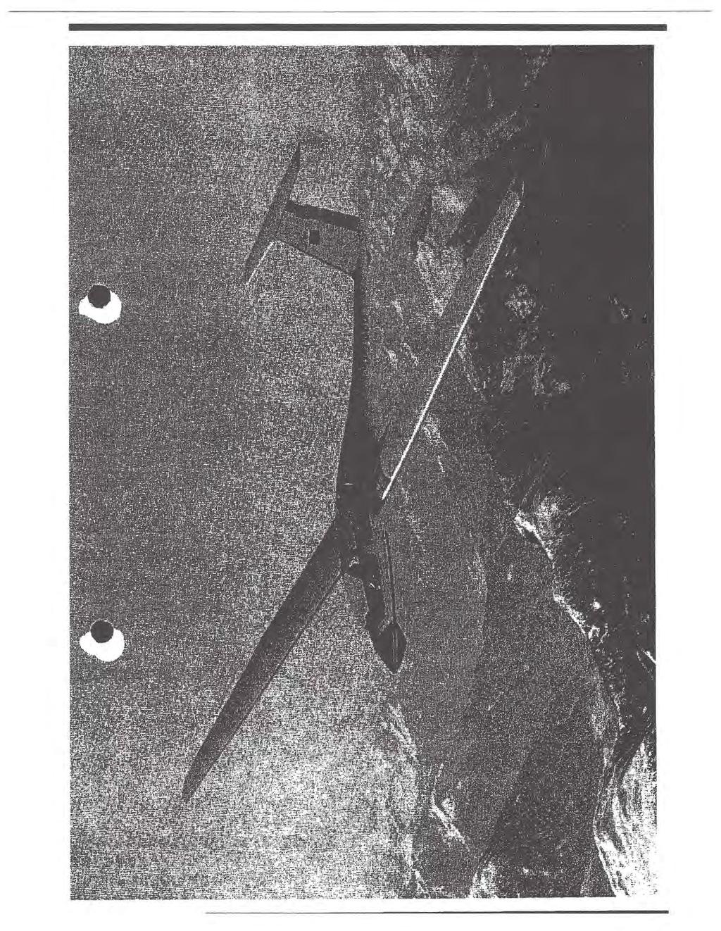
7 FLIGHT HANDBOOK TWIN ASTIR 5 I '
8 FLIGHT HANDBOOK TWIN ASTIR 5a The sailplane TWIN-ASTIR TRAINER is derived from the TWIN-ASTIR. The differences are fixed sprung undercarriage with disc brake, and the deletion of the wing ballast tanks. Therefore, the remarks In the flight handbook and the maintenance handbook concerning retractable undercarriage and water tanks do not apply to the TWIN-ASTIR TRAINER. The wheel brake of the TWIN-ASTIR TRAINER is a disc brake. The brake cylinder with the storage tank for brake fluid Is mounted on the undercarriage box. The marks for minimum and maximum reserve must be observed. For refilling use brake fluid DOT 3 (amber)
9 FLIGHT HANDBOOK TWIN ASTIR 6 I. 5 Description The TWIN ASTIR Is a high performance two seater sailplane with a T-tail, fitted with a retractable undercarriage, upper surface airbrakes and water ballast tanks in the wings. This sailplane is manufactured using the latest techniques in industrial Glass fibre construction. it is designed for training, high performance and simple aerobatic flying. Technical Data: Span 17.5 m (57.4 ft.) Length 8.1 m (26.6 ft.) Height 1.6 m (5.2 ft.) Aspect Ratio Operating Limits Airworthiness Group Wing Area 17.8 m (191.6ft. 2 } Maximum Flying Weight 650 kg (14351bs) Maximum Wing Loading 36.5 kg/m 1 (7.841bs/ft. 2 ) (U, Utility, LFSM} The LFSM (Lufttuchtigkeitsforderung fur Segelflugzeuge und Motorsegler) published are the basic rules and requirements for the licensing of a new type of glider or motor glider in Germany Permitted operating conditions. The plane is licensed for: 1 Flight in VMC 2. Simple Aerobatics (Loops, Stall turns, Lazy eight, Chandelle and SpiA). 3. Cloud flying {When fitted with suitable Instrumentation as defined in section 11. 3) Minimum equipment 1. 2 Air speed Indicators reading to 300 km/hr (162 kts, 187 mph) 2. 2 Altimeters. 3. Full Harness Straps in front and back cockpit. 4. Parachute or back cushion at least 7 cm (3 inch) thick. 5. Loading limit plaque in front and back cockpit. 6. Flight Limits plaque. 7. Flight Handbook.
10 FLIGHT HANDBOOK TW-IN ASTIR 7 Cloud Flying. For cloud flying the additional instruments listed below must be installed. 1. Variometer. 2. Electric turn and slip indicator. 3. Magnetic Compass (Compensated inside the glider) Maximum -Speeds Maximum permitted speed in calm air Maximum permitted speed in rough air Maximum Manoeuvring speed Maximum winch launch speed Maximum Aerotow speed VNE = 250 km/h ( 135 kts, 155 mph} I Vs = 170 km/h ( 92-kts, 105 mph) VM = 170 km/h ( 92 kts, 1-05 mph) Vw = 120 km/h ( 65 kts, 74 mph) VT = 170 km/h ( 92 kts, _105 mph) Conditions in rough air are similar to those encountered in rotors, cjouds, whirlwinds and when overflying mountain ranges. Manoeuvring speed is the maximum speed at which full control deflections may be used. At maximum speed (VNE) the control deflections should be restricted to 1/3 of the full range. Air speed indicator markings mph = kts = km/h -Green arc mph == kts = km/h -Yellow arc I at 155 mph = 135 kts = 250 km/h (MSB315-64/3}-- Red line at 65 m ph = 55 kts = 102 km/h - Yellow triangle (recommended minimum appr. speed} Position Errors The airspeed indicator must be connected to the fouowing sources: Pitot head in the tail fin. static vents side of the fuselage between the two seats. Using a cal-ibrated ASI the posaion error is not greater than ± 2 km/h or 1 kt or 1.2 mph. A calibration curve is therefore not necessary. If. 5 Flight envelope. The sailplane design limit load factors are as follows: At manoeuvring speed At VNE (Brakes closed and calm air} 14. September 2004
11 FLIGHT HANDBOOK TWIN ASTIR Welghtllmlts Maximum permitted weight without water ballast Including water ballast. Maximum permitted weight of non lifting parts 650 kg (1435 lbs) 650 kg {1435 lbs) 470 kg (1036 lbs) Centre of gravity position The approved range of centre of gravity positions during flight is 260 mm {10.24 inches) to 460 inm (18.11 inches) behind the reference point, equivalent to 24.7% to 43.6% of the M.A.C. of the wing. The reference point is the front edge of the wing at the wing root. The approved centre of gravity range does not get exceeded by the payload distribution specified in the loading plan The exact position of the centre of gravity at flying weight can be calculated according to VI Load scheme TWIN ASTIR Minimum load in the front seat for all flight. Maximum load in the front seat Maximum load in the back seat Maximum load ln both seats Maximum load in the baggage compartment. 70 kg (154 lbs) 110 kg (242 lbs) 110 kg {242 lbs) 220 kg (485 lbs) 10 kg ( 22 lbs) Ballast must be used on the front seat to compensate If the front seat load is lower than 70 kg (154 lbs). The maximum flying weight of 650 kg {1435 lbs) must not be exceeded. Waterballast may only be taken on until the maximum flying weight is reached. Water ballast can not be used to compensate lf the load in the front seat Is too low
12 F LIG H T HANDBOOK TWI N ASTIR 9 Date of wetghlng: carried out by. Equipment list used for weighing (dale) Empty (Weight} kg!lb9 Position of cg empty behind refe- rence mm/ inches Maximum total payload kg/lbs ~ r "- -,-... ~._...,_ - - -
13 FLIGHT H A ND BOOK TWIN ASTIR Tow hooks For Aerotow: Nose hook "E 75''. For Winch launch : Safety back release hook "G 73". The E 75 and the G 73 Tost hooks are limited to 36 months after installation or 2000 launches which ever occurs first, at which time they are to be recertified by the manufacturer Wuk link ttrength recomme~~~~~ if'f,).!.:ai /t~ )"ZJ t.a:; Winch launch and aerotow ~0 kg 1323 ± 66 lbs (ie. Tost weak link colour code black-red) rrt- 1 ~~)-- :1'/ ll. 11 Tire Pressure Tire size ,5-2.8 atm ,8 PSI Crosswinds The maximum crosswind component approved for fake off and landing, Is 20 km/h {11 kts, 12 mph).
14 FLIGHT HANDBOOK TWIN ASTIR 11 U ~ 13 Required placards front and rear cockpit Maximum flying weight Without Waterballast With Waterballast 650 kp 1435 lbs 650 kp 1435 lbs Airspeed limits. Never exceed V Ne In Rough Air Vs On Airotow Vr On Winch or Auto Launch Vw Airbrakes Open V of Manoeuvring VA km/hr knots " m ph Payload (Pilot and Parachute). Minimum in Front cockpit for all flight. Less must be compensated with ballast secured in the seat Maximum load front Maximum load back 70 kg 110 kg 110 kg 154 lb 242 lb 242 lb Simple aerobatics air speeds Recommended entry speed Loop Stall turn Spin Chandelle.km/hr knots aerobatics with waterballast is not allowed m ph September 2004
15 FLIGHT HANDBOOK TWIN ASTIR 12 Required placards Check before launch Full and free movement of controls? Parachute secured? Straps tight and locked? Pedals adjusted and locked? Brakes closed and locked? Trim correctly adjusted? Altimeter adjusted? Canopy locked? Cable on correct hook? Beware: - Crosswind! - Cable breakt Front Cockpit Canopy Jettison and Emergency Exit - Pull red handles on right and left of canopy fully back together - Push canopy up and away with the left hand - Release safety harness - Stand up and get out over left or right side depending on the altitude - When using a manual parachute grip release and pull firmly to full extent after 1-3 seconds By canopy release front and back Tire Pressure 39,8 PSI 2,8 atm Maximum weak link strength 1323 lbs 600 kg Left undercarriage door. Baggage maximum 22 lbs 10 kg Baggage compartment
16 F L J G HT HA N D K TW J N AS T I R Symbols Undercarriage retract Canopy open CanopyJeUson Waterballaat Jetlson.Trim Airbrakes IOJ) Wheel brake
17 F Ll G HT HA N D B 0 0 K TW I N AS T t R 14 Symbols t i Cable release Air-vent. Top left of front Instrument panel QQ Pe~al adjustment Top right of front Instrument panel Total energy compensation tube
18 FLIGHT HANDBOOK TWIN ASTIR 15 Ill. Emergency procedures Ill. 1 Exit from a spin Exit from a spin can be accomplished by - Full opposite Rudder -- Neutralise Stick - Ailerons should be central - When rotation stops centralise rudder and pull out gently Ill. 2 Emergency canopy Jettisoning and exit. The spacious cockpit allows unhindered exit in an emergency. lt Is advisable to keep to the following order: a) Pull red handles on left and right back together and push canopy upwards and away with the left hand. b) unlock safety belts c) Stand up and get out over left or right side depending on the attitude. d) When using a manual parachute grip release handle and pull firmly" to full extent after 1-3 seconds. Ill. 3 Landing with retracted undercarriage lt is possible on hard and soft ground without risk of overturning. Approach as normal and touch down on two points. Ill. 4 Others Flying In rain Wet or lightly iced wings have little noticeable effect on flying. Thick ice deposits on the wing increase the stalling speed by about 10 km/h = 6 kts. Stall Stall out of straight flight or a turn: Neutralise stick and opposite rudder to any turn. Ground Loops The glider has no tendency to ground loop whilst taking off. However if a wing touches or the direction changes by.more than 15 degrees during a take off release immediately.
19 FLIGHT HANDBOOK TWIN ASTIR 16 Ill. 5 Instruments specifications Basic equipment: Airspeed The installation error of an airspeed Indicator Is not greater than 2 km/h or 1 kt. or 1,2 mph using the pitot tube In the tail fin and the static vents side of"the cockpit. The original certification was carried out using a Winter 6FMS4-2 and a PZL PR 400 S Airspeed indicator. A similiar FAA approved airspeed indicator to meet TSO C 2 reading to 300 km/h (162 kts, 187 mph) may be used. Altimeter The original certification was carried out using a Winter 4FGH 10 and. a PZL 12 S Altimeter. A simillar FAA approved altimeter to meet TSO C 10 with a range to feet may be used. Nur USA-Export

20 FLIGHT HANDBOOK TWIN ASTIR 17 IV. Normal operation VI. 1 Cockpit and controls Front Seat. 1 Stick 5 Undercarriage lever 2 Rudder pedals 6 Release knob 3 Airbrake lever and wheelbrake 7 Canopy jettison 4 Trim -lever 8 Water ballast jettison Ventilator top of Instrument panel left side Rudder pedal adjustment top of instrument panel right side.

21 '. FLIGHT HANDBOOK TWIN ASTIR 18 IV. 1 Cockpit and controls Back seat. 1 Stick 4 Trim lever 2 Rudder pedals 5 Undercarriage lever 3 Airbrake lever and wheelbrake 6 Release knob 7 Canopy jettison
22 F L I G H T H A N 0 B 0 0 K T W l N AS T I R 19 IV. 2 Daily preflight Inspection 1. a) Open canopy. b) Check the 4 wing fastenlngs Inside the fuselage If locked. c) Visually check all controls inside the cockpit. d) Check for foreign bodies. e) Te~t controls for full and free movement. f) Check tire pressure atm. = PSI g) Check condition of both hooks. h) Check functioning of releases and wheelbrake. 2. a) Check top and bottom of wing for damage b) Check ailerons for condition, freedom of movement and play. c) Check alrbrakes for condition, locking and fit. 3. Check fuselage for damage especially on the underside. 4. Check tall unit for correct assembly and that safety lock Is in position. 5. Check condition of the tailskid. 6. Check the pitot tube, total energy venturi and static vents are clean. 7. Repeat step 2 for right wing. B. Check static vents. After heavy landings or excessive flight loads the entire glider should be checked. The wings and tailplane should be removed for these checks and if any damage is found an inspector should be consulted. The plane should not be flown before any damage is repaired.
23 FLIGHT HANDBOOK TWIN ASTIR 20 Preflight Inspection Checkpoints compare IV. - 2 \ I N
24 FLIGHT HANDBOOK TWIN ASTIR 21 IV. 3 Control checks before take off 1. Check all the controls for full and free movement. 2. Check undercarriage lever Is fully forward and locked down. 3. Check that the ballast limitations are being adhered to. 4. Check safety straps and parachute are firmly fastened. 5. Check altimeter is adjusted to zero or airfield height. 6. Check that transmitter is switched on and set to airfield frequency. 7. Check trim is neutral. 8. Check canopy is closed and locked. 9. Check airbrakes are closed and locked. IV. 4 Take off Winch launch Trim lever should be in central position. Maximum winch launch speed is 120 km/h (65 kts, 74 mph). The glider has a release hook in front of the wheel. Winch launches cause no difficulties at all allowed centre of gravity positions and wing loadlngs. The plane has no tendency to balloon up or to swing on the ground. One should push forward slightly on the stick below about 100 metres (330 ft) in the case of fast launches from a powerful winch. When the cable slackens pull the release firmly to its limit. The undercarriage should not be retracted during a winch launch. Aerotow Trim lever should be in central position. Maximum aerotow speed is 170 km/h {92 kts, 105 mph). Aerotow should preferably use the nose hook. The recommended length of tow rope is m ( ft.). The glider can be controlled with coordinated rudder and aileron using full movements if required. There is no tendency to swing In a strong crosswind. The glider can be lifted off at about 70 km/h (38 kts, 44 mph). The glider lifts off without ass.lstance at a speed of about 80 km/h (43 kts, 50 mph) if the stick Is kept in the neutral position. The undercarriage can be retracted during aerotow at a reasonable height.. The yellow release handle is mounted on the Instrument panel a.nd must be pulled to its limit when releasing.
25 FLIGHT HANDBOOK TWIN ASTIR 22 IV. 5 Free flight lt Is possible to fly the glider over the entire speed range in all attitudes. Full co11trol movements are only allowed up to the manoeuvring speed 170 km/h (92 kts, 105 mph). At higher speeds the controls should be used with the appropriate care. IV. 6 Slow flying and stalling The glider gives clear warning when about to stall by a distinct shaking of the elevator. The stalling speed depends on the wing loading and the condition of the plane. The following are guidelines: Single seater Weight 470 kg = 1034 lbs Double seater Weight 650 kg = 1430 lbs Without Airbrakes 66 km/h {36 kts, 41 mph) Without Airbrakes 80 km/h (43 kts, 50 mph) With Airbrakes 75 km/h (40,5 kts, 47 mph) With Airbrakes 90 km/h {49 kts, 46 mph) If the stick is.pulled back further the glider goes into a controllable high rate of sink, during which rudder and aileron turns can be flown at up to 15 degrees of bank. When the stick is released the glider returns to a normal flying attitude immediately. After the stick Is pulled back quickly the glider pitches nose down and the bank can still be controued with aileron. IV. 7 High speed flight There is no tendency for flutter to develope within the permitted speed range. Above 170 km/h (92 kts, 105 mph) control movements should be restf1icted to 1/3 of full range. The airbrakes limit the speed to under VNE In a 45 dive even at maximum flying weight. IV. 8 Cloud flying The minimum Instrumentation required for flying In cloud is: Air speed indicator Variometer Turn and Slip Altimeter Compass
26 FLIGHT HANDBOOK TWIN ASTIR 23 Experience to date shows that the ASJ does not get affected by icing. If the manouvering speed is exceeded unintentjonajiy, puij out the airbrakes to avoid overstressing. In emergency open brakes and leave cloud at about 170 km/h (92 kts, 105 mph). IV. 9 Simple Aerobatics The gjider is licenced for the following aerobatics (no waterbauast): 1. Loop Entry speed Maximum g exit speed 180 km/h (97 kts, 111 mph) ea. 3 g ea. 180 km/h (97 kts, 111 mph) 2. Stall turn Entry speed 180 km/h (97 kts, 111 mph} At 140 km/h (76 kts, 87 mph) slowly apply rudder. Shortly before the top apply opposite aileron. Note: The stall turn is difficult to carry out because of the high moment of inertia. If a. tallslide Is accidently Initiated during the climb lock all controls in the centre position. 3. Spin (possible in aft e.g. positions only} Preparation. Decrease speed slowly to 80 km/h (43 kts, 50 mph) pull stick back and give full rudder. Glider spins slowly. Rotation rate is one turn every 3 seconds with a height loss of about 100 m (300ft.) per turn. Exit Rudder fully opposite against direction of turn, neutr~lise stick then pull out slowly after rotation has stopped.
27 FLIGHT HANDBOOK TWIN ASTIR ChandeiJe Entry speed * 170 km/h (92 kts, 105 mph) Pull up to fly 90 turn. During turn decrease speed and exit from turn with rudder and aileron. Chandelle should be completed heading in opposite direction. NB: For twoseater configuration increase entry speed by 20 km/h (12 mph, 11 kts). IV. 10 Approach and landing Normal flying practice Is to approach at 100 km/h = 54 kts. The airbrakes are sufficiently powerful for steep approaches. The use of brakes causes the glider to be slightly nose heavy, so that the glider holds the required speed by itself. Avoid changing the alrbrake setting during the roundout to avoid heavy landing. IV. 11. Flight with waterballast The water tanks are In the front of the wings and can hold about 50 I (11 gal.) per wing. The tanks are filled through the openings on the top of the Wings. The cap can be removed with a pin. There is no noticeable water movement when the tanks are partially filled because of baffles installed within the t~nks. There must always be equal amounts of water in each tank to avoid affecting the stability in roll. The white lever on the right hand side of the cockpit should be pulled back to empty the tanks. The outlet Is underneath the fuselage behind the wheel. lt takes about 4 minutes to empty the tanks. it Is strongly recommended that the tanks are emptied before landing out of field.
28 FLIGHT HANDBOOK TWIN ASTIR 25 V. Rigging and derlgglng V. 1 Rigging The fuselage must" be held firmly In a horizontal position when rigging. lt is recommended to use a fuselage stand or the trailer fittings are used. The glider can be rigged by 4 people. 1. Wings Unlock the 4 main wing fittings in the fuselage. Unlock the airbrakes on the wings. Guide the right wing into the fuselage. The safety catches on the fuselage fittings should now be released, and on gently moving the wing to and. fro will be heard to snap into place. Next guide the left wing l"nto the fuselage. Move the wing tips up or down so that the pin on the end of the spar stub Is lined up with the appropriate hole in the opposite wing root and slide into place. Next release the safety catches on the left hand fuselage fittings and by gently moving the wing to and fro they too can be made to snap into place. Original wing-fuselage connection: To secure the wing fittings the safety catches (1) have to be turned so that the pins (2} are pressed to the angled slots. Moving the wing tip strongly to and fro enables the safety catches to be sufficiently turned (4). They should be hand tight and should not reach the end of the angled slot. Wing-fuselage connection according to SB : To secure the wing-fuselage connection in the closes position, the knurled nut { 1) must be turned into the threaded socket (2) so that the socket is drawn against the red rings which are held by the guide pins (3). By means of moving the wing tips for and aft, the knurled nut can be secured tight (4) while securing the guide pins however, must not strike against the end of the milled selector of the shaft guide Rev. 7
29 FLIGHT HANDBOOK TWIN ASTIR 25a Original wing-fuselage connection: a r--mv;m opened Wing-fuselage connection according to SB : a geoffnet r-~~~~~~~opened 2 b closed c sured max. position Check: The red rings at the fuselage connection rods must be covered by the threaded sockets. the socket (or the knurled nut ace. to SB } must be tightened hand tight. In the closed, but not secured position {b), the wing bolt cannot be removed from. the locking. 2. The aileron and brake connections lie behind the spar. The.short connecting rods in the fuselage are fitted with quick lock fasteners which must be coupled onto the balls on the linkages that move inside the wings. After rigging the connections should be examined to check that the sprung catches are properly inserted $0 that they project some mm out of the locks. Also after coupling the quick-lock fasteners, check that the ball can not be extracted by twisting the lock back and forth. Do this gently with not more than 10 lbs pull. Check all the control connecting rods and locks in a methodical order Rev. 7
30 FLIGHT HANDBOOK TWIN ASTIR Tailplane Before assembly is commenced the front cover must be opened and the rotating wing bolt pulled out to the limit. The tailplane can be positioned by standing behind the rudder. The tailplane can be rested on top of the fin with the elevator angled upwards so that the snap lock fastener on the elevator push rod can be attached to the ball on the elevator horn. The front of the tailplane can then be lowered and pushed back onto the three pins. lt Is then necessary to tighten the wing bolt clockwise to secure the tailplane. The assembly is complete when the wing bolt is sufficiently tight that there is no play in any direction. The cover provides a safety measure as it can only be attached with the wing bolt horizontal. If necessary the wing bolt has to be turned a 1/4 turn to suit. Derigging is carried out in the opposite order and the wing bolt is turned anticlockwise and pulled fully out. Checks to be made after assembly 1. Check that the 4 main wing fittings are locked. 2. Check that aileron and brake quick-actions locks are properly located on the knobs. 3. Ensure that the tow hook is functioning correctly. 4. Test the operation of the wheelbrake and the pressure of the air in the tire. 5. Check that the tailplane is securely seated and that the elevator push-rod is connected. 6. Rudder movement. Oerlgglng Derigglng is carried out in the opposite order and this case it does not matter which wing is removed first. Excessive fore and aft rocking of the wing tips should be avoided. V. 2 Storage When the glider Is stored the canopy should be locked. To tie down the wi11g, a rope can be pulled through the wing tip skidso' For ground handling the rotating tall wheel should be used.

31 FLJG.HT HANDBOOK TWIN ASTIR 27 V. 3 Transport We recommend the use of a closed trailer for transporting the glider. The parts must be carefully supported and secured so they cannot slide. 1. Fuselage A fuselage trolley moulded to the shape of the fuselage and positioned in front of the main wheel The mlnimum length of the trolley should be 400 mrn and it can be attached to the wing fittings if required. The tail skid should be secured so that it cannot slide sideways. 2. Wings The minimum length for the spar support should be 200 mm and should start at the face of the root rib. The mounting must be padded well with foam rubber or felt. The mounting under the aileron Inboard end should be a shaped mounting block with a minimum length of 300 mm and height of 400 mm. The mounting must be padded with felt. 3. Tailplane Either horizontal on padded supports with the upper surface downwards and secured with straps or vertical supported on the leading edge in shaped mounting blocks. Profile drawings are avaitable for the manufacture of f-uselage, wing and tailplane fittings. V. 4 Maintenance of the glider The entire surface of the glider is coated with weather resistant white polyester gelcoat. The greatest care should be taken in maintainln g the fibre glass surface of the glider. Luke warm water should be used to wash off dust, grease, dead flies and other dirty marks. More resistant dirt shquld be removed by using a mild cleaning agent. Only special silicon-tree preparations should be used in maintaining the painted surfaces. 0 Z-Spezialreiniger..., D 2, Fa. W. Sauer and Co., 5060 Bensb~rg or Reinigungspolish Fa. Lesonal).
32 F L I'G HT HA N D B 0 0 K T W I N AS T I R 28 Although very resistant the glider should be protected as much as possible against rain and dampness. Water that has seeped in should be dealt with by storing the glider in a dry place, frequently turning over the dismantled parts. The most effective way to clean the canopy is to use a special perspex cleaner but if necessary iuke warm water can be used. A soft, clean cloth or chamois-jeather should be employed to wipe the canopy down. Never rub perspex with anything dry. The Safety harness should be regularly checked for damage and general wear. The metal parts of the harness should be frequently checked for corrosion. Because of its position, the winch launch hook is susceptible to getting very grimy and muddy. lt must therefore be frequently inspected tor damage, cleaned and greased. When the seat-well Is removed the hook can easily be taken out. Remove the connecting wire from the. lever and take out the retaining screws. For reconditioning, the tow hook should be sent with the record card to the tow hook manufacturer, Tost. For further details the manufacturers manuals should be consulted. The cables.and pulley for the nose and belly hooks should be checked tor wear during the yearly inspection. The main wheel tire pressure should be kept at 2.5 to 2.8 atmospheres "( psi). The wheelbrake Is of a dru~ type (tor SIN's optional as a hydraulic disc brake). Drum brake: The bowden cab)e can be adjusted. The adjustment Is canied out by moving the Bowden cable at the drum end. Disc brake: The main b(&ke cylinder and th~ brake fluid reservoir are located under the rear seat. Use only brake fluid according to specification OOT3/ OOT4. During removing the main wheel for cleaning, greasing or changing the tire the Bowden cable must be disconnected from the brake lever (drum brake} or the brake cylinder must be removed (disc brake). Do not open the brake fluid hose. Screw the M 6 threaded special tool. onto one side of the axle and take out the screws and the spindle. Remove the screws that hold the brake-lever in place. Take the wheel out by pulling it downwards. Clean all the parts and before reassembly smear all of them with grease. Before assembling the glider the pins and sockets at the joints between wings and fuselage, and tailplane and fuselage, should be cleaned and greased TM
33 FLIGHT HANDBOOK TWIN ASTIR 29 VI. Appendices VI. 1 Flight Performance Flying weight 470 (1036) 560 (1234} 650 (1435) kg {lbs) Wing loading 26.4 (5.4) 31.5 (6.5) 36.5 {7.5) kg/m 1 (I bs/ft. 2 ) Best glide Angle at a speed of 95 (51) 105 (57) 110 (60) km/hr (kts) Minimum sink 0.62 (2.03) 0.68 (2.23) 0.73 (2.3) m/sec {ft./sec) at a speed of 75 (40) 80 (43) 90 (49) km/hr (kts) Vl E o VELOciTY J kts) 0 10 ~ ~ ~ ~ w ~ oo oo m m m m FLUGGESCHWINDIGKEIT [ km/hj r- 1 ~. m ~ E (.!) - "" =1/XJ 0 UJ a z 2 ~ ~000 3 (.) ill 4 ~ z 5 (./) ~ - If ~... ~ ~~' f ' -..>... ~', " GESCHWINDIGKEI1SPOLARE TWIN -ASTIR FLIGHT POLAR --~Bso~ ~''Vi> v1b
34 FLIGHT HANDBOOK TWIN ASTIR 30 VI. 2 Service and Maintenance instructions Regular service. The following schedule of service should be carried out every 100 hours or at the annual inspection, which occurs first. 1. The entire glider should be checked for cracks, holes and bumps. 2. All fittings should be inspected for satisfactory condition (play, scores and corrosion). 3. All metal parts should be examined for corrosion, cracks, deformation and If necessary reconditioned and freshly protected. 4. Check that there is no play in the wing and tailplane to fuselage fittings. 5. The control linkages (Bearings, stops, fittings, hinges and control cables) should be inspected and replaced if there Is evidence of bending or corrosion. 6. The controls Including the brakes should be submitted to a functional test and the control deflections checked. 7. If the controls do not move free throughout their range, search for the cause and correct. 8. The undercarriage should be Inspected and the wheel and brake checked to be in good condition. 9. The tow hooks should be treated in accordance with their appropriate maintenance manual. 10. Check the pitot for the ASI is clear and that the tubing to an instruments is in good condition and free of leaks or kinks. 11. The condition and calibration of all instruments should be checked and any other equipment inspected. 12. Equipment and Instruments should be checked against the equipment list. 13. Check markings and placards. 14. After repair or change of equipment, the weight table should be updated with the new empty weight and Center of Gravity py weighing or calculation.
35 FLIGHT HANDBOOK TWIN ASTIR 31 After extended storage check accordingly to regular service pos. 1 to 11 and inspect for evidence of rodents and birdness. VI. 3 Reference to Repairs The attached repair instructions give information for the execution of minor repairs. Major repairs, in accordance with the glider information sheet are only permitted to be carried out by an authorised aircraft works. Grob will name a company with the appropriate qualifications in any individual case. VI. 4 Installation, maintenance and examination of the release hooks One Is bound by the Maintenance Manuals for the nose hooks 'E 72' and 'E 75' published In May 1975 and the Maintenance Manual for the belly hooks 'Europa G 12: and 'Europa G 73' published In May VI. 5 Determination of the Center of Gravity The determination of the center of gravity Is made with the undercarriage lowered and the glider supported on two scales at heights such that an Incidence board of 600 : 24 angle is set horizontal on the back of the fuselage. The. reference plane lies at the front of the wing at the root. The distances a and b are measured with the help of a plumb line. The empty weight is the sum of the two weights G1 and G2.
36 F L 1 G H T H A N D K T W I N.A. S T I R 32 Procedure tor determlnlg C. of G. empty 600.2[, GL = G1 + G2 ~.G.,, b Datum Lme: Front edge of the wing at the root :_evei Means. With a 600:24 Incidence Board set up horizontal on the top of the rear fuselage. Weigt-~t on main-wheel Weight on tail-skid -~ Empty Weight Gl "" Gt Dtstance to main-wheel Distance-to tail-sl<id Gt - G2 ~..:. G2 = a= b -- kg I lbs kg /lbs kg I lbs mm 1 inches mm/ inches Empty Weight C. of G. X - j- mm.'inches behind Datum Line 'he ;1ea3urements to determine the empty weight, the empty weight G JI G. and the loading limitations must always be taken with the ;:J i,(1er A:nply of waterballast Con11ertio;, frnrn Kg to lbs inches multiply with
37 FLJGHT HANDBOOK TWIN ASTIR 33 If the limits of the empty weight C. of G. positions and the loading limitations chart are adhered to the C. of G. of the loaded glider will be within the permitted range. Empty Weight Range of C. of G. behind Datum Forward Aft kg lbs mm inches mm inches lt should be noted that to make use of the maximum load the maximum admissable load for non-lifting parts must not be exceeded. The weight of the non-liftlng parts Is the sum of the fuselage, tailplane and maximum load In the fuselage and must not exceed 470 kgs (1036 lbs) or the maximum load permitted in the fuselage must be correspondingly decreased. The Centre of Gravity should be recalculated after repair, repainting, the installation of additional equipment or when a period of 4 years he.s elapsed after the last weighing. The empty weight, empty weight C. of G. posiuon anct maximum load, should be recorded after each weighing on page 9 of the. Flight Han.dbook.
38
LS7 WL, VH-XJB INFORMATION FOR PILOTS
 LS7 WL, VH-XJB INFORMATION FOR PILOTS John Hudson (Revised April 2017) TABLE OF CONTENTS 1. General Information/Specifications 2. Handling Notes 3. Technical Details 4. Daily Inspection 5. Water Ballast
LS4-a VH-XOK INFORMATION FOR PILOTS
 LS4-a VH-XOK INFORMATION FOR PILOTS John Hudson (Revised April 2017) TABLE OF CONTENTS 1. General Information/Specifications 2. Rigging 3. Handling Notes 4. Water Ballast System 5. Radio The LS4a XOK is
SAILPLANE FLIGHT MANUAL
 WSK "PZL-ŚWIDNIK" S.A. Al. Lotników Polskich 1, 21-045 Świdnik, POLAND SAILPLANE FLIGHT MANUAL Type: PW-6U Serial No.: Registration: Document No.: PW-6U / IUL / I / 03 US M Date of Issue: November 18,
SAILPLANE FLIGHT MANUAL
 WSK "PZL-ŚWIDNIK" S.A. Al. Lotników Polskich 1, 21-045 Świdnik, POLAND SAILPLANE FLIGHT MANUAL Type: PW-6U Serial No.: Registration: Document No.: PW-6U / IUL / I / 03 US M Date of Issue: November 18,
Pilot Handling Guide
 Pilot Handling Guide Puchacz SZD-50-3 VH- GRI + WQX These notes are a conversion guide only and not a substitute for the Manufacturer s Flight Manual. General notes on conversions.2 Basic overview.2 External
Ops Manual 05 Page 40
 Ops Manual 05 Page 40 Ops Manual 05 Pg 41 I. PRE -FLIGHT PREPARATION. (a) EXTERNAL CHECKS --Before entering the cockpit, a detailed inspection of the sailplane for proper condition should be carried out
PILOT S NOTES FOR THE BLANIK L-13 SAILPLANE
 Czechoslavak Aeronautical Works PILOT S NOTES FOR THE BLANIK L-13 SAILPLANE 2nd REVISED EDITION - 1967 AERONAUTICAL WORKS - LET KUNOVICE - CZECHOSLOVAKIA PILOT S NOTES FOR THE BLANIK L-13 SAILPLANE 2 FOREWORD
DISCLAIMER: This scanned version of the Schweizer 2-33A Sailplane manual is provided without warranty of completeness or accuracy.
 DISCLAIMER: This scanned version of the Schweizer 2-33A Sailplane manual is provided without warranty of completeness or accuracy. It is solely as a service to builders of scale model aircraft who are
FLIGHT MANUAL. for a sailplane. Allstar PZL Glider Sp. z o.o. SZD-54-2 Perkoz. Serial No: Registration:
 Allstar PZL Glider Sp. z o.o. for a sailplane Model: Serial No: Registration: SZD-54-2 THIS SAILPLANE IS TO BE OPERATED IN COMPLIANCE WITH INFORMATION AND LIMITATIONS CONTAINED HEREIN. THIS DOCUMENT SHOULD
Flight Manual LS1-f. 0 Amendments, list of effective pages, table of contents
 0 Amendments, list of effective pages, table of contents 0.1 Amendments Any revision of the present manual, except actual weighing data, must be recorded in the following table and in case of approved
HIGH PERFORMANCE SAILPLANE ENDORSEMENT
 HIGH PERFORMANCE SAILPLANE ENDORSEMENT ENGINEERING, DATA AND PERFORMANCE TYPE Name : Instructor: GFA: GFA: (Signature/Name) Satisfactorily Completed on: / / 1 THE ENDORSEMENT QUESTIONNAIRE In order to
Southern Eagles Soaring
 Southern Eagles Soaring N56LS Standard Cirrus Disassembly / Assembly Procedure. Version 2, 2017 You landed out so what now? First, hopefully you made arrangements with someone who has a hitch on their
Brief Maintenance Manual DAR-Solo
 Brief Maintenance Manual DAR-Solo Sofia 2009 Page: 1 TABLE OF CONTENTS Introduction 3 Limitations and safety information 4 General view of DAR-Solo prototype 7 Technical Data 8 Inspection before and after
Annex E(M) - Final inspection checklist - monowheel
 - Final inspection checklist - monowheel") Annex E(M) - Final inspection checklist - monowheel A/C Reg... Owner...Kit S/N...Date... (U.K. Only) L.A.A No...Inspector...Insp. No... Note: This check list only covers specific items for inspection of
Annex E(M) - Final inspection checklist - monowheel A/C Reg... Owner...Kit S/N...Date... (U.K. Only) L.A.A No...Inspector...Insp. No... Note: This check list only covers specific items for inspection of
Pre Solo Written For Schweizer 2-33 Glider. Eagles Sport Aviation Club
 Pre Solo Written For Schweizer 2-33 Glider Eagles Sport Aviation Club Student Date: Instructor 1) What is the maximum gross weight for the 2-33? Empty Weight? 2) What position should the trim level be
BASIC AIRCRAFT STRUCTURES
 Slide 1 BASIC AIRCRAFT STRUCTURES The basic aircraft structure serves multiple purposes. Such as aircraft aerodynamics; which indicates how smooth the aircraft flies thru the air (The Skelton of the aircraft
Darling Downs Soaring Club Inc
 Darling Downs Soaring Club Inc Rigging and De-Rigging Instructions LS7 XOW Overview Page 2 Rigging page 3 De-Rigging page 19 Overview It is the pilot s responsibility to make sure that the trailer is fully
L-23 Super Blanik Rigging (assembly/disassembly) Guide Maj Carl Kerns
 Guide Maj Carl Kerns") L-23 Super Blanik Rigging (assembly/disassembly) Guide Maj Carl Kerns The L-23 Blanik is a difficult Sailplane to rig (assemble). The wings are heavy and are secured via a single
L-23 Super Blanik Rigging (assembly/disassembly) Guide Maj Carl Kerns The L-23 Blanik is a difficult Sailplane to rig (assemble). The wings are heavy and are secured via a single
Flight Manual Schleicher ASK 21 3
 Flight Manual Schleicher ASK 21 3 I.3 Contents I. General I.1 Log of revisions I.2 Pages included I.3 Contents I.4 3-Side-View I.5 Description (Beginning of JAR22-required and LBA-approved part.) II. Operating
FLIGHT MANUAL SUPPLEMENT
 FLIGHT MANUAL SUPPLEMENT HUSKY / RF 8001 SKIS This supplement is valid for The Husky A-1. The following derivates of the Husky may use this Supplement after the approval of a minor change to operate the
SCHEMPP-HIRTH FLUGZEUGBAU GmbH., KIRCHHEIM/TECK FLUGHANDBUCH / FLIGHT MANUAL
 SCHEMPP-HIRTH FLUGZEUGBAU GmbH., KIRCHHEIM/TECK Discus-2a Discus-2b FLUGHANDBUCH / FLIGHT MANUAL 0.1 Erfassung der Berichtigungen / Records of revisions Lfd. Nr. der Berichtigung Abschnitt Seiten Datum
LAA TYPE ACCEPTANCE DATA SHEET TADS 315 EV-97 AND EV-97A EUROSTAR. Issue 6 SB EV97-UK-08 and 09 added dated
 Issue 6 SB EV97-UK-08 and 09 added dated 26.3.08 1. UK contact Nigel Beale, Cosmik Aviation, Burnside, Deppers Bridge, Southam, Warks, CV47 2SU. Tel: 07940 266521. E-mail: cosmik@skydrive.co.uk 2. Description
Principles of glider flight
 Principles of glider flight [ Lecture 2: Control and stability ] Richard Lancaster Email: Richard@RJPLancaster.net Twitter: @RJPLancaster ASK-21 illustrations Copyright 1983 Alexander Schleicher GmbH &
Логотип. Hangglider PHANTOM. Manual
 Логотип Hangglider PHANTOM Manual Kiev, Ukraine 2005 TABLE OF CONTENTS Section 1. General information 1.1. Introduction 1.2. Main data 1.3. Operation limitations 1.4. Flying tests Section 2. Set up procedure
Weighing your Seabee
 Weighing your Seabee Note: The following procedure must be supervised and signed off by a qualified A&P and the final paperwork must be included in the Aircraft Records. The actual weights must be included
SF 25 C - F A L K E. F L I G H T M A N U A L and Maintenance Manual S C H E I B E A I R C R A F T G M B H ROTAX 912 A ( ) ROTAX 912 S ( ) motorglider
 ROTAX 912 S ( ) motorglider") S C H E I B E A I R C R A F T G M B H D - 7354 Heubach, Am Flugplatz 5 Tel.: ()7173 / 184 286 Fax: ()7173 / 185 587 e-mail: info@scheibe-aircraft.de F L I G H T M A N U A L and Maintenance Manual SF 25
S C H E I B E A I R C R A F T G M B H D - 7354 Heubach, Am Flugplatz 5 Tel.: ()7173 / 184 286 Fax: ()7173 / 185 587 e-mail: info@scheibe-aircraft.de F L I G H T M A N U A L and Maintenance Manual SF 25
Flight Control Systems Introduction
 Flight Control Systems Introduction Dr Slide 1 Flight Control System A Flight Control System (FCS) consists of the flight control surfaces, the respective cockpit controls, connecting linkage, and necessary
CIRCLING THE HOLIGHAUS WAY -
 CIRCLING THE HOLIGHAUS WAY - OR DO YOU REALLY WANT TO KEEP THE YAW STRING CENTERED? BY RICHARD H. JOHNSON ANSWERS: 1. During Straight Flight - YES, that minimizes drag and maximizes the sailplane's performance.
Maintenance Schedule for Gliders and Powered Gliders
 Aircraft Mfr Model S/N Rego Total Hours Total Launches Engine Hours Date Inspecting Engineer GNZ Rating Job No Section 1: Required Documents, Manuals and Data 1.1 Documents Carried in Aircraft: DI Book
REPLACING THE AFT RUDDER CABLES
 REPLACING THE AFT RUDDER CABLES Note: You must have the assistance of a qualified Aircraft Mechanic to perform this procedure. A logbook entry with the mechanics signature is required. Please read these
SUPPLEMENT TO AIRCRAFT FLIGHT MANUAL FOR MOTOR-DRIVEN ROPE WINCH TYPE RPM 11/01
 SUPPLEMENT TO AIRCRAFT FLIGHT MANUAL FOR MOTOR-DRIVEN ROPE WINCH TYPE RPM 11/01 (Langenthaler-Winch) Aircraft-Manufacturer: Avions Robin SA Type of Aircraft: Robin DR 300-180R DR400-180R DR 400-200R DR
CIRRUS AIRPLANE MAINTENANCE MANUAL MODELS SR22 AND SR22T CHAPTER 55-40: RUDDER GENERAL. Rudder 55-40: RUDDER. 1. General
 CIRRUS AIRPLANE MAINTENANCE MANUAL Rudder CHAPTER 55-40: RUDDER GENERAL 55-40: RUDDER 1. General The rudder provides airplane directional (yaw) control and includes a rudder trim tab used for yaw trim
Tecnam Eaglet Standard Operating Procedures and Maneuvers Supplement
 Tecnam Eaglet Standard Operating Procedures and Maneuvers Supplement Normal Takeoff Flaps Take Off Trim set Fuel pump on Check for traffic Line up on white stripe Full power Stick should be located in
Pre-Paint>Fuselage>Empennage>Fit vertical tail fin. Objectives of this task: Materials and equipment required: Fit the spar extender
 Pre-Paint>Fuselage>Empennage>Fit vertical tail fin Objectives of this task: To fit the vertical tail fin to the fuselage, including fitting the static probe, static tube, optional strobe light wiring and
CIRRUS AIRPLANE MAINTENANCE MANUAL
 RUDDER 1. GENERAL The rudder provides airplane directional (yaw) control and includes a rudder trim tab used for yaw trim adjustment. The rudder is of conventional design with skin, spar and ribs manufactured
C-130 Reduction in Directional Stability at Low Dynamic Pressure and High Power Settings
 C-130 Reduction in Directional Stability at Low Dynamic Pressure and High Power Settings The C-130 experiences a marked reduction of directional stability at low dynamic pressures, high power settings,
CIVIL AVIATION AUTHORITY SAFETY REGULATION GROUP MICROLIGHT TYPE APPROVAL DATA SHEET (TADS) NO: BM47 ISSUE: 11
 NO: BM47 ISSUE: 11") TYPE: MAINAIR BLADE (1) MANUFACTURER: P & M Aviation Ltd, Unit B, Crawford Street, Rochdale, Lancashire, OL16 5NU (2) UK IMPORTER: - (3) CERTIFICATION: BCAR Section, Advance Issue as amended October 1988
TYPE: MAINAIR BLADE (1) MANUFACTURER: P & M Aviation Ltd, Unit B, Crawford Street, Rochdale, Lancashire, OL16 5NU (2) UK IMPORTER: - (3) CERTIFICATION: BCAR Section, Advance Issue as amended October 1988
GUIDE TO CS-VLA FLIGHT REQUIREMENTS. TL 1.13 Issue 4 1 Jan 2008
 The full content of CS VLA, the design requirements for certified very light aircraft, can be downloaded from the EASA website at http://www.easa.eu.int/home/certspecs_en.html This Technical Leaflet has
robart HOW-TO Series Model Incidence Meter
 robart HOW-TO Series Model Incidence Meter The term incidence is something of a misnomer since this highly versatile tool is capable of measuring or comparing angles other than incidence of a wing or tail.
Thruster T600 (N) & (T) 390kg
 & (T) 390kg") TYPE: Thruster T600 (N) & (T) 390 (1) MANUFACTURER Thruster Aircraft (UK) Continued Support: Thruster Aircraft LLP North Hanger Wickenby Airfield Langworth, Lincs LN3 5AX (2) UK IMPORTER: N/A (3) CERTIFICATION:
TYPE: Thruster T600 (N) & (T) 390 (1) MANUFACTURER Thruster Aircraft (UK) Continued Support: Thruster Aircraft LLP North Hanger Wickenby Airfield Langworth, Lincs LN3 5AX (2) UK IMPORTER: N/A (3) CERTIFICATION:
The following is a walk-around that should be done on each day of use before starting the airboat.
 Do not enter the cage area for any reason unless the key switch and battery switch are both in the off position. Audibly alert and visually check for people in the cage area, path of the propellers or
Tiger Moth basic handling notes
 Tiger Moth basic handling notes by David Phillips To move the aeroplane, lift the tail by the tailplane strut, gripping as close as possible to the fuselage. The aeroplane will be neutrally balanced when
- Single Seat Sport Sailplane - C 30 EDELWEISS
 FLIGHTANDOPERATIONALMANUAL For - Single Seat Sport Sailplane - C 30 EDELWEISS Serial Number : 11 Registration: 4X-GJA Certified by Republic of France General Secretariat of Civil Aviation Edition i Certified
CIVIL AVIATION AUTHORITY SAFETY REGULATION GROUP MICROLIGHT TYPE APPROVAL DATA SHEET (TADS) NO: BM - 26 ISSUE: 6
 NO: BM - 26 ISSUE: 6") TYPE SNOWBIRD MK IV (1) MANUFACTURER: Original: Noble Hardman Aviation Ltd Continued Airworthiness: BMAA (2) UK IMPORTER: Parts may be obtained from Snowbird Aviation, Bremia, Stagshead, Llangeitho, Tregaron,
TYPE SNOWBIRD MK IV (1) MANUFACTURER: Original: Noble Hardman Aviation Ltd Continued Airworthiness: BMAA (2) UK IMPORTER: Parts may be obtained from Snowbird Aviation, Bremia, Stagshead, Llangeitho, Tregaron,
Mandatory Bulletin BO
 Zakład Szybowcowy Jeżów EASA No. AP 4 MANDATORY BULLETIN BO-78-0-0 Page: Pages: Mandatory Bulletin BO-78-0-0 Aircraft Type / Model: PW-6U Glider Serial Numbers: 78.0.08 78.0.0, 78.04.0 78.04.09, as well
II.E. Airplane Flight Controls
 References: FAA-H-8083-3; FAA-8083-3-25 Objectives Key Elements Elements Schedule Equipment IP s Actions SP s Actions Completion Standards The student should develop knowledge of the elements related to
ASW 27 Flight Manual. 8. The "Multiprobe" must be installed into its socket in the nose of the fin.
 NOTE: Integrated (wet inner surface) water ballast tanks are vented at the wing tip below the winglet to wing intersection. That port must never be taped over! 8. The "Multiprobe" must be installed into
WIPLINE 3450 SEAPLANE FLOATS
 FOUND SUPPLEMENT M400-S08 Transport Canada Approved Flight Manual Supplement For WIPLINE MODEL 3450 SEAPLANE FLOATS This supplemental manual is applicable to Wipline Model 3450 seaplane float equipped
AIRCRAFT PRIMARY CONTROLS A I R C R A F T G E N E R A L K N O W L E D G E
 1.02.02 AIRCRAFT PRIMARY CONTROLS 1. 0 2 A I R C R A F T G E N E R A L K N O W L E D G E CONTROLLING AIRCRAFT AIRCRAFT CONTROL SYSTEM In general, we use control inputs of the following devices in cabin:
BRAKE WINCH RUP 503-[T/BT] EQUIPMENT FOR LIFTING LOADS. AT 053-[T/BT] xx
![BRAKE WINCH RUP 503-[T/BT] EQUIPMENT FOR LIFTING LOADS. AT 053-[T/BT] xx](/thumbs/88/115945274.jpg "BRAKE WINCH RUP 503-[T/BT] EQUIPMENT FOR LIFTING LOADS. AT 053-[T/BT] xx") Reference number: BRAKE WINCH RUP 503-[T/BT] EQUIPMENT FOR LIFTING LOADS DESIGNATED USE The brake winch RUP 503-[...]T series is a load lifting / lowering device. Device is equipped with safety brake for
Reference number: BRAKE WINCH RUP 503-[T/BT] EQUIPMENT FOR LIFTING LOADS DESIGNATED USE The brake winch RUP 503-[...]T series is a load lifting / lowering device. Device is equipped with safety brake for
NORMAL TAKEOFF AND CLIMB
 NORMAL TAKEOFF AND CLIMB CROSSWIND TAKEOFF AND CLIMB The normal takeoff is one in which the airplane is headed directly into the wind or the wind is very light, and the takeoff surface is firm with no
Series D-D PILOT S NOTES
 CFM-Aircraft SHADOW Series D-D PILOT S NOTES These Pilot s Notes are relevant excerpts from the original CFM-Aircraft manufacturer s Pilot s Notes / Service Manual (PN SH/D and SM SH/D first issued on
User Guide. Tripod. flowtech 75 / 100 Tripod. Part No. S S
 User Guide flowtech 75 / 100 Tripod Tripod Part No. S2051-0001 S2052-0001 EN www.sachtler.com TM Copyright 2018 All rights reserved. Original Instructions: English All rights reserved throughout the world.
Building Instructions ME 163 B 1a M 1:5 Turbine
 Building Instructions ME 163 B 1a M 1:5 Turbine Thank you for choosing our kit of the Me-163B. We ask you to read the instruction once in advance before building this kit in order to avoid mistakes. Make
CRYOGENIC TANK SERVICES - CHART RECORDER MANUAL
 CRYOGENIC TANK SERVICES - CHART RECORDER MANUAL Pressure Chart Recorder / Temperature Chart Recorder / Dual Recorder Portable Mechanical Chart Recorder for the accurate measurement and recording of Pressure
Single Engine Complex Training Supplement PA28R-201 Piper Arrow III (Spring 2016 Revision)
") Single Engine Complex Training Supplement PA28R-201 Piper Arrow III (Spring 2016 Revision) V-speed Quick Reference V-Speed KIAS Description Airspeed Indicator Marking VSO 55 Stall speed in landing configuration
Single Engine Complex Training Supplement PA28R-201 Piper Arrow III (Spring 2016 Revision) V-speed Quick Reference V-Speed KIAS Description Airspeed Indicator Marking VSO 55 Stall speed in landing configuration
Chapter 2 Rigging. Cutting Wire Rope. Anchoring Wire Rope to Drum. Winding Wire Rope Onto Drum
 Chapter 2 Rigging Cutting Wire Rope The wire rope must be tightly seized on both sides of the point where the wire rope will be cut, as shown in Figure 2-1. Seize the wire rope with either seizing wire
Winnipeg Headingley Aero Modellers. Things About Airplanes.
 Winnipeg Headingley Aero Modellers Things About Airplanes. Table of Contents Introduction...2 The Airplane...2 How the Airplane is Controlled...3 How the Airplane Flies...6 Lift...6 Weight...8 Thrust...9
CSSna HIAWK FLOATPLANE WNER'S MANUAL SUPPLEMENT D CES-100-3/73
 CSSna HIAWK FLOATPLANE WNER'S MANUAL SUPPLEMENT D709-13-CES-100-3/73 2220 108 PERFORMANCE - SPECIFICATIONS FLOATPLANE 1620ft 148 GROSS WEIGHT lbs SPEED: Top Speed at Sea Level mph u Cruise, 75% Power at
Lectric Cycles Mid-Drive Electric Motor Installation
 Lectric Cycles Mid-Drive Electric Motor Installation This write-up describes the installation of a Lectric Cycles electric motor. The model is the e-rad Mid-Drive 750 Watt conversion kit, installed on
Ottawa Remote Control Club Wings Program
 + Ottawa Remote Control Club Wings Program Guide line By Shahram Ghorashi Chief Flying Instructor Table of Contents Rule and regulation Quiz 3 Purpose of the program 4 Theory of flight Thrust 4 Drag 4
Assembly Instructions. -Cantilever Boat Lifts
 Assembly Instructions -Cantilever Boat Lifts Winch Instruction Page Safety Information 1. The winch is built for the multipurpose of hauling and lifting operations. It is not to be used as a hoist for
LIGHTWEIGHT TRIWALKER OWNER S HANDBOOK
 LIGHTWEIGHT TRIWALKER OWNER S HANDBOOK Triwalker Owner s Handbook (Z25987 Rev A) Page 1 of 12 CONTENTS 1. Contents 2. Introduction 3. Parts Description 4. Personal Safety 5. Adjustments for Comfort 6.
Operation Manual Guillotine Cutter RC-5
 Operation Manual Guillotine Cutter RC-5 Technical Specifications General Safety/Operating Instructions Using the Guillotine Cutter/Crimper Blade Change Instructions Maintenance Instructions This is a detailed
Aviation Merit Badge Knowledge Check
 Aviation Merit Badge Knowledge Check Name: Troop: Location: Test Score: Total: Each question is worth 2.5 points. 70% is passing Dan Beard Council Aviation Knowledge Check 1 Question 1: The upward acting
BlueArrow. Venus DLG. Construction and Flight Manual. Note: Read this manual carefully before construction and flight!
 BlueArrow Venus DLG Construction and Flight Manual Note: Read this manual carefully before construction and flight! 1 1. Introduction Thank you for choosing this fantastic Venus DLG brought to you by BlueArrow
STOL CH rd Edition Drawings, dated April 16, 2012 Summary of changes from Edition 2 Revision 1 to Edition 3.
 STOL CH 750 3 rd Edition Drawings, dated April 16, 2012 Summary of changes from Edition 2 Revision 1 to Edition 3. Page Date Drawing Title 75-G-0 04/12 Three View Drawing 1. Edition 3 75-G-1 04/12 Drawings
3/8" Dr. Air Butterfly Impact Wrench
 8192106 3/8" Dr. Air Butterfly Impact Wrench Owner s Manual Read and understand all instructions before use. Retain this manual for future reference. Specifications Construction: Polished aluminum and
Improvement of an Artificial Stall Warning System for Sailplanes
 Improvement of an Artificial Stall Warning System for Sailplanes Loek M. M. Boermans and Bart Berendsen Delft University of Technology, Faculty of Aerospace Engineering P.O.Box 5058, 2600 GB Delft, The
ANNEX TO TYPE CERTIFICATE No. ULL - 07 / 2003 a
 Letecká amatérská asociace ČR, Light Aircraft Association CR Ke Kablu 289, 102 00 Praha 10, Hostivař tel: sekretariát 271 085 270 fax: 27 10 85 596 e-mail: laacr@laacr.cz http://www.laacr.cz Type certificate
MAGNETIC INDOOR CYCLING BIKE
 MAGNETIC INDOOR CYCLING BIKE SF-B1805 USER MANUAL IMPORTANT! Please retain owner s manual for maintenance and adjustment instructions. Your satisfaction is very important to us, PLEASE DO NOT RETURN UNTIL
CSA 2018 ANNUAL QUIZ. 1. List the following speeds for each ship you fly. Assume single person. Solitaire Grob103 SGS 232 LS-4.
 CSA 2018 ANNUAL QUIZ Name: Address: Pilot Certificate Number: Phone Number: E-Mail: 1. List the following speeds for each ship you fly. Assume single person. Solitaire Grob103 SGS 232 LS-4. Vs L/D Min
MAINTENANCE PROCEDURE FOR X 650
 MAINTENANCE PROCEDURE FOR X 650 X 650 25. juli 2005-1/6 MAINTENANCE PROCEDURE FOR X 650 2 ND STAGE WARNING: This maintenance procedure is only for appointed Scubapro technicians that completed a course
LOAD CHARTS RT540E 85% STABILITY ON OUTRIGGERS 75% STABILITY ON RUBBER
 LOAD CHARTS RT540E 85% STABILITY ON OUTRIGGERS 75% STABILITY ON RUBBER SERIAL NUMBER 1 2 TABLE OF CONTENTS GENERAL NOTES... 4 WT. REDUCTIONS / LINE PULLS & REEVING INFO / HOIST PERFORMANCE. 5 LIFTING AREA
A. TO PREPARE THE MACHINE FOR USE.
 INSTRUCTION MANUAL FOR THE ML120 STRINGING MACHINE. CONTENTS: A. TO PREPARE THE MACHINE FOR USE. 1. The assembly of frame with console and tooltray. 2. Fixing the lever of the tension unit. 3. Putting
FAA-S-ACS-6 June 2016 Private Pilot Airplane Airman Certification Standards. Task ACS Settings
 FAA-S-ACS-6 June 2016 Private Pilot Airplane Airman Certification Standards Cessna 172: mixture rich, carb heat out if below the green arc. Clearing Turns all manuevers! Task ACS Settings Traffic Pattern
Front Cover Picture Mark Rasmussen - Fotolia.com
 Flight Maneuvers And Stick and Rudder Skills A complete learn to fly handbook by one of aviation s most knowledgeable and experienced flight instructors Front Cover Picture Mark Rasmussen - Fotolia.com
CIVIL AVIATION AUTHORITY SAFETY REGULATION GROUP MICROLIGHT TYPE APPROVAL DATA SHEET (TADS) NO: BM14 ISSUE: 9
 NO: BM14 ISSUE: 9") TYPE: (1) MANUFACTURER: Mainair Sports Ltd now supported by P & M Aviation Ltd, Unit B, Crawford Street Rochdale, Lancashire, OL16 5NU. (2) UK IMPORTER: N/A (3) CERTIFICATION: BCAR Section S, Advance Issue
TYPE: (1) MANUFACTURER: Mainair Sports Ltd now supported by P & M Aviation Ltd, Unit B, Crawford Street Rochdale, Lancashire, OL16 5NU. (2) UK IMPORTER: N/A (3) CERTIFICATION: BCAR Section S, Advance Issue
XI.B. Power-On Stalls
 XI.B. Power-On Stalls References: AC 61-67; FAA-H-8083-3; POH/AFM Objectives Key Elements Elements Schedule Equipment IP s Actions SP s Actions Completion Standards The student should develop knowledge
SKI SPECIFICATIONS INSTALLATION, MAINTENANCE, SERVICE INSTRUCTIONS & ILLUSTRATED PARTS LIST
 SKI SPECIFICATIONS INSTALLATION, MAINTENANCE, SERVICE INSTRUCTIONS & ILLUSTRATED PARTS LIST AIRGLAS MANUAL NO. L 44000-105 (Rev C) FOR SKI SERIAL NO. S 1 THRU 1000 AIRGLAS MODEL L 44000-11 FSN 1630-912-3166
Tru Trak Sulky Proline Mid Size Mower Attachment
 Form No. -7 Tru Trak Sulky Proline Mid Size Mower Attachment Model No. 00 000000 and Up Operator s Manual Domestic English (EN) Contents Page Introduction................................ Safety.....................................
INSTRUCTION AND MAINTENANCE HANDBOOK. Wing Type MILD 16. II) Technical specifications - Performances
 Technical specifications - Performances") INSTRUCTION AND MAINTENANCE HANDBOOK Wing Type MILD 16 I) Drawings II) Technical specifications - Performances III) Instructions for use IV) Maintenance Instruction and Maintenance Handbook MILD 16 EDITION
INSTRUCTION AND MAINTENANCE HANDBOOK Wing Type MILD 16 I) Drawings II) Technical specifications - Performances III) Instructions for use IV) Maintenance Instruction and Maintenance Handbook MILD 16 EDITION
Whisper 1400 Glider Operation Manual
 Whisper 1400 Glider Operation Manual Specifications: Wingspan: 55 (1400mm) Length: 32.5 (825mm) Wing area: 323 sq. in. Weight: 16 oz.(453g) Ace R/C Whisper 1400 Glider R/C Sailplane (4104-F) Distributed
LOAD CHARTS RT890E METRIC DIN / ISO / 75%
 LOAD CHARTS RT89E METRIC DIN / ISO / 75% 232729 SERIAL NUMBER RT89E - S/N 232729 1 RT89E - S/N 232729 2 TABLE OF CONTENTS GENERAL NOTES...4 WEIGHT REDUCTIONS / LINE PULLS & REEVING INFO / RIGGING CHART
Operator s Manual. All-Terrain Wheelchair
 Operator s Manual All-Terrain Wheelchair By Brandon Calavan Ana Groff Steve Benn Dylan Rinker Sebastian Pineo Team 1 Faculty Advisor: John Enderle Teaching Assistant: Sarah Brittain Client: Melody Kettle
LAA TYPE ACCEPTANCE DATA SHEET TADS 206. Issue 4 Correction to Max Coolant Temps Dated 27/2/09
 Issue 4 Correction to Max Coolant Temps Dated 27/2/09 1. UK contact Manufacturers defunct. Spares and advice available from Raymond Proost or Fiona Luckhurst, Shadow Flight Centre, Hangar 4, Old Sarum
Falcon 3 145, 170, 195 and Tandem Owner / Service Manual
 Falcon 3 145, 170, 195 and Tandem Owner / Service Manual January 2007 - Second Edition Removing The Sail From The Airframe And Short Packing The Glider Many maintenance and repair procedures will require
Aerodynamic Terms. Angle of attack is the angle between the relative wind and the wing chord line. [Figure 2-2] Leading edge. Upper camber.
![Aerodynamic Terms. Angle of attack is the angle between the relative wind and the wing chord line. [Figure 2-2] Leading edge. Upper camber.](/thumbs/82/86661300.jpg "Aerodynamic Terms. Angle of attack is the angle between the relative wind and the wing chord line. [Figure 2-2] Leading edge. Upper camber.") Chapters 2 and 3 of the Pilot s Handbook of Aeronautical Knowledge (FAA-H-8083-25) apply to powered parachutes and are a prerequisite to reading this book. This chapter will focus on the aerodynamic fundamentals
Chapters 2 and 3 of the Pilot s Handbook of Aeronautical Knowledge (FAA-H-8083-25) apply to powered parachutes and are a prerequisite to reading this book. This chapter will focus on the aerodynamic fundamentals
VIII.A. Straight and Level Flight
 VIII.A. Straight and Level Flight References: FAA-H-8083-3; FAA-H-8083-25 Objectives Key Elements Elements Schedule Equipment IP s Actions SP s Actions Completion Standards The student should develop the
ANGEL 2000 glider ARF ASSEMBLY MANUAL. Specifications: MS: 129
 WWW.SEAGULLMODELS.COM ASSEMBLY MANUAL ANGEL 2000 glider Graphics and specifications may change without notice. MS: 129 ARF Specifications: Wingspan---------------78.7 in ( 200cm). Wing area---------------582.8sq.in
Visualized Flight Maneuvers Handbook
 Visualized Flight Maneuvers Handbook For High Wing Aircraft Third Edition For Instructors and Students Aviation Supplies & Academics, Inc. Newcastle, Washington Visualized Flight Maneuvers Handbook for
LAPL(A)/PPL(A) question bank FCL.215, FCL.120 Rev PRINCIPLES OF FLIGHT 080
/PPL(A) question bank FCL.215, FCL.120 Rev PRINCIPLES OF FLIGHT 080") PRINCIPLES OF FLIGHT 080 1 Density: Is unaffected by temperature change. Increases with altitude increase. Reduces with temperature reduction. Reduces with altitude increase. 2 The air pressure that acts
PRINCIPLES OF FLIGHT 080 1 Density: Is unaffected by temperature change. Increases with altitude increase. Reduces with temperature reduction. Reduces with altitude increase. 2 The air pressure that acts
USER GUIDE TO POWER ASSISTED BIKES
 USER GUIDE TO POWER ASSISTED BIKES 1 PAGE CONTENTS Page. 3 Unpacking Page. 3-4 Easy steps to get started Page. 5 General Assembly Instructions Page. 6 Aligning H/Bars, Page. 7 Tightening pedals onto Crank
XI.C. Power-Off Stalls
 References: FAA-H-8083-3; POH/AFM Objectives Key Elements Elements Schedule Equipment IP s Actions SP s Actions Completion Standards The student should develop knowledge of stalls regarding aerodynamics,
Semi Freddo Snow kite [Ram Air]
![Semi Freddo Snow kite [Ram Air]](/thumbs/89/97639710.jpg "Semi Freddo Snow kite [Ram Air]") User manual Semi Freddo Snow kite [Ram Air] This manual gives you detailed instructions on how to use your new Semi Freddo kite. We recommend you take your time to read the instructions. In case you have
User manual Semi Freddo Snow kite [Ram Air] This manual gives you detailed instructions on how to use your new Semi Freddo kite. We recommend you take your time to read the instructions. In case you have
Use this key to determine which sections of this Product Manual apply to your job.
 R710 Product Manual Contents Warnings and Important Information 3 Recommended Use 4 Product Information 5 Technical Data 5 Before & During Every Transfer 6 Inspection 6 SoloLift Scale (optional) 6 SoloVest
PF30 Inspection & Maintenance Manual
 PF30 Inspection & Maintenance Manual Version 1.4 (September 2011) 1 Contents 1. Warning!!!!!!!!!! 3 2. Terminology! Figure 1: POWERFAN PF30 and Drope!!!! 4! Figure 2: POWERFAN PF30 with belt guard retracted!!
Build This World Record Fuselage Model
 Build This World Record Fuselage Model Here You Have Complete Instructions and Plans to Build a Plane of Sure-fire Performance that Established a World Record at the 1932 National Airplane Model Competition
600 / 600FC OWNER'S MANUAL
 PROGRESSION 600 / 600FC OWNER'S MANUAL Issue 2 / Version E - Dec. 10, 1997 Copyright 1997 GAMMA Sports - All Rights Reserved PROGRESSION 600 / 600FC OWNER'S MANUAL TABLE OF CONTENTS PAGE 1... WARRANTY
RIDE Inc. Rigscape Service Rig Procedures
 2016 RIDE Inc. Rigscape Service Rig Procedures Special Instructions/Conditions of Use Reading user procedure manual prior to use is essential Only persons that have been deemed competent in the operation