Fighter aircraft design. Aerospace Design Project G. Dimitriadis
|
|
|
- Priscilla Gardner
- 6 years ago
- Views:
Transcription


1 Fighter aircraft design Aerospace Design Project G. Dimitriadis
2 General configuration The elements of the general configuration are the following: Wing Wing placement Airfoil Number of engines Number and placement of engine air intakes Horizontal tail Canards Number of fins Other control surfaces
3 Wings Modern high performance fighters have one of three wing types: Trapezoidal Delta Sweptback with low aspect ratio Lower performance fighters (trainers, ground attack aircraft etc) can also have high aspect ratio sweptback wings, just like transport aircraft. Trapezoidal, Delta and low aspect ratio sweptback wings can fly at subsonic or supersonic speeds. Such wings have low aspect ratios and are thin in order to minimize wave drag (drag due to shock waves). Aircraft with high aspect ratio sweptback wings cannot fly supersonic, except under special circumstances (e.g. powered dives). Such wings have high aspect ratios and are thicker in order to accommodate a thick main spar.


4 Shock waves All wings must lie inside the conical shock wave generated by the fuselage nose of an aircraft flying at supersonic conditions.
5 Delta wings Advantages: Delta wings have a long root chord and therefore can have a thick main spar while retaining a low thickness- to- chord ratio. They also have larger wing area than trapezoidal wings with the same aspect ratio. This means low wing loading even during maneuvers. There is a lot internal volume for fuel and landing gear. At low speed conditions they can produce a lot of additional lift when placed at high angle of attack, thanks to the leading edge vortices. Delta wing aircraft do not require a horizontal tail. Disadvantages: Higher viscous drag due to the large wing area. High induced drag at subsonic conditions due to low aspect ratio. Bad deep stall. Pitch control is achieved by deflecting upwards the trailing edge control surfaces in order to produce a nose up moment. This reduces the total amount of lift generated by the wing. This problem can be overcome by incorporating a horizontal tail or lifting canards.


6 Aircraft with Delta wings MiG- 21: Cropped Delta with tail Eurofighter Typhoon: Cropped Delta with canards JAS 39 Gripen: Cropped Delta with canards Mirage III, IV, V, 2000: Tailless cropped Delta IAI Kfir: Upgraded Mirage V with canards F- 102 Delta Dagger and F- 106 Delta Dart: Tailless cropped Delta
 Chengdu J-")


7 Aircraft with Delta wings (2) Chengdu J- 10: Cropped Delta with canards Dassault Rafale: Cropped Delta with canards Saab 37 Viggen: Compound Delta with canards Saab 35 Draken: Compound Delta Shenyang J- 8: Delta wing with tail Concorde: Ogive Delta
8 More on Delta wings The pitch control and bad deep stall disadvantages of Delta wings led to several variations: Compound Delta or Ogive Delta: the inboard sweep is generally higher so as to create even stronger leading edge vortices and delay stall to even higher angles. Exception: Saab 37 Viggen. The Ogive Delta also reduces supersonic drag. Horizontal tail: Provides additionally stability in pitch and therefore the wing can produce more lift. Tail elevator provides pitch control Canards: They are usually all- moveable and provide additional pitch control. The aircraft is usually statically unstable. Note also that flaps are difficult to use with a tailless Delta configuration. Delta wings are generally cropped. The pointy wingtip is difficult to manufacture and structurally weak. Furthermore, cropped Delta wings delay vortex bursting. The centre of lift lies aft on a Delta wing. This means that the horizontal tail can only be effective if it lies even further aft. Usually the tail is highly swept and can be placed on a highly swept fin.
9 Specifications of some delta wing aircraft Aircraft Aspect Ratio Maximum Mach Service Range Sea level High altitude Ceiling MiG ,400 ft 1,470 km Eurofighter ,000 ft 2,900 km Typhoon JAS ,000 ft 1,600 km Grippen Mirage ,000 ft 1,550 km F ? ,000 ft 2,900 km Chengdu J ,055 ft 550 km Dassault ,000 ft 1,852 km Rafale Saab ,100 ft 2,000 km Viggen Concorde 1.7? ,000 ft 7,222 km
10 Trapezoidal wings In trapezoidal wings, the leading edge sweeps back but the trailing edge sweeps forward. Some Delta wings also feature a slight sweep forward angle at the trailing edge. Advantages Better performance than Delta wings at transonic speeds and during transition to and from supersonic conditions. They do not require upwards deflection of the trailing edge control surfaces for pitch control and therefore do not lose lift. Their centre of lift lies further forward and therefore the tail must not lie too far back on the fuselage. They are preferred for stealth applications. Flaps can be easily used. Disadvantages: High wing loading. They stall at much lower angles of attack than Delta wings. This problem is overcome using Leading Edge (Root) extensions (LEX or LERX) and/or canards.


: with tail F-")

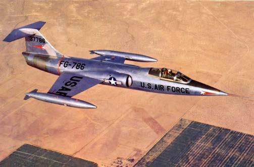
11 Aircraft with trapezoidal wings F- 18: Trapezoidal wing with tail F- 16: Trapezoidal wing with tail F- 22: Trapezoidal wing with tail Su- 57 (T- 50): Trapezoidal wing with tail F- 35: Trapezoidal wing with tail F- 104: Trapezoidal wing with T- tail
12 Specifications of some trapezoidal wing aircraft Aircraft Aspect Ratio Maximum Mach Service Range Sea level High altitude Ceiling F ? ,000 ft 2,017 km F- 18 Super?? 1.8 >50,000 ft 2,346 km Hornet F >50,000 ft 550 km F ? 2.25 >65,000 ft 2,960 km with external fuel tanks Su ? 2 65,000 ft 3,500 km F ? ,000 ft 2,200 km F ? ,000 ft 1,600 km
13 More on trapezoidal wings Trapezoidal wings are mostly used by the US. They are nearly always combined with a conventional horizontal tail and single or twin fin. They are nearly always combined with LEX. Some trapezoidal wings look like highly cropped Delta wings (F- 16 for example). Modern trapezoidal wings have very highly swept leading edges, approaching the sweep of Delta wings.
14 Sweptback wings Both the leading and trailing edges are swept back. Sweptback wings have very similar characteristics to trapezoidal wings but have larger wing area. Advantages: Higher wing area and hence lower wing loading. The centre of lift lies between that of trapezoidal and Delta wings. They have the trapezoidal wing advantages compared to Delta wings. Disadvantages: They require LEX, just like trapezoidal wings. They create higher viscous drag than trapezoidal wings.


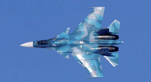
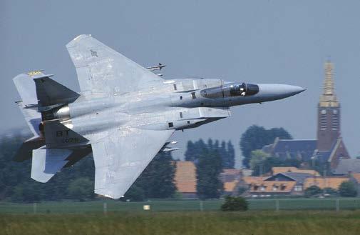
15 Aircraft with swept wings MiG- 29, 35: Swept wing with tail MiG- 25, 31: Swept wing with tail Mirage F1: Swept wing with tail Su- 27, Su- 35: Swept wing with tail Su- 30, Su- 34: Swept wing with tail and canard F- 15: Swept wing with tail
16 Specifications of some swept wing aircraft Aircraft Aspect Ratio Maximum Mach Service Range Sea level High altitude Ceiling MiG ,100 ft 1,430 km MiG- 35? ,340 ft 2,000 km MiG ,915 ft 1,730 km MiG ,600 ft 3,000 km with external fuel tanks Su ,523 ft 3,530 km Su ,100 ft 3,540 km Su ? ,800 ft 3,000 km Su >1.8 49,200 ft 1,100 km Mirage F1? ,600 ft 1,400 km Super? ,900 ft 2,000 km Etendard F ,000 ft 1,967 km
17 More on swept wings Swept wings are mostly associated with the Soviet design tradition. The leading edges of swept wings are highly swept, more than those of previous generation trapezoidal wings. All aircraft with swept wings have a conventional but several modern Sukhoi fighters also have canards. Most of these aircraft are heavy fighters with two engines and twin fins.
18 Wing aspect Ratio Statistical data from Raymer Jet fighters and trainers have Aspect Ratios ranging from 4 to 5.5.
19 Wing placement High- wing: Stable in roll and therefore anhedral is generally required to reduce stability. Affords good ground clearance for external stores/engine pods/propellers. Short landing gear. High wings can block upwards pilot visibility (bad for turning and climbing). Low- wing: Unstable in roll and therefore dihedral is generally required to increase stability. Very bad ground clearance for external stores/engine pods/propellers. Long landing gear if external stores/engine pods/propellers are necessary. Mid- wing: Neutral roll stability, the dihedral can be zero. OK ground clearance for external stores/engine pods/propellers. Short landing gear. NB: Sweep can have an effect similar to dihedral. According to Raymer, 10 degrees of sweep have the same effect as 1 degree of dihedral. Supersonic aircraft have sweep angles up to 60 degrees, i.e. effective dihedral of up to 6 degrees.
20 Wing aerodynamic centre Position of trapezoidal and swept wing aerodynamic centre: Subsonic conditions: ¼ of the mean aerodynamic chord Supersonic conditions: 0.4 of the mean aerodynamic chord (Raymer). For Delta wings, the aerodynamic centre lies at 2/3 of the root chord from the apex of the wing. Cropping the wing tends to move the aerodynamic centre forward More details: J.E. Lamar and W.J. Alford, Jr., Aerodynamic- centre considerations of wings and wing- body combinations, NASA TN D- 3581, October 1966 J.H.B Smith, J.A. Beasly and A. Stevens, Calculation of the lift slope and aerodynamic centre of cropped Delta wings at supersonic speeds, Aeronautical Research Council Current Papers, C.P. No. 562, 1961
21 Airfoil thickness Airfoil thickness ratio as a function of Mach number (from Raymer) Subsonic aircraft: 12-16% Supersonic aircraft: 4-6%

22 Supersonic airfoils Most supersonic airfoils are variations of two shapes: Double wedge (or diamond) Biconvex (or circular arc) More examples: W.F. Lindsey, B.N. Daley and M.D. Humphries, The flow and force characteristics of supersonic airfoils at high subsonic speeds, NACA TN 1211, March 1947
23 Number of engines and intakes For modern aircraft, the choice of engine number is relatively simple: Heavy fighter aircraft: 2 engines. Light fighter aircraft and trainers: 1 engine. There are several possibilities for intake placement: A single intake in the fuselage nose. A single or double intake under the fuselage. Two intakes on the side of the fuselage. Above the wing for a low- wing configuration. Below the wing for a high- wing configuration. In front of or below the wing for a mid- wing configuration. Note that the inlet shape, number and placement depends not only on the engine flow requirements but also on the flight Mach number (due to shock waves).
 can rotate around its root axis.")
24 Tail and canards In modern fighter aircraft both tails and canards are generally all- movable. There is no elevator, the entire tail (or canard) can rotate around its root axis. An all- movable tail is often referred to as a stabilator. Deflected stabilator of a F- 16
25 Mach tuck and buzz Aircraft flying at high transonic and supersonic speeds experience a severe nose- down moment known as Mach tuck. The aerodynamic centre of the wing moves backwards; the moment of the lift around the centre of gravity increases in the nose down direction. The downwash of the wing decreases; the effective angle of attack of the tail increases and so does the tail lift. All- movable tails are much better at dealing with this phenomenon than fixed tails with elevators. If a shock wave forms on a fixed tail behind the elevator hinge it can cause elevator buzz. All- movable tails can overcome this phenomenon but aileron buzz is still common in fighter aircraft at transonic conditions.
26 Canards Modern fighter canards are always all- movable and their function is pitch control only. They are known as control- canards In steady level flight their angle of attack is zero and, as they are symmetric, they do not create any lift. They do not contribute to pitch stability, in fact their role is often to destabilize an otherwise stable aircraft. As they are all- movable they cannot stall even at very high angles of attack. The flight computer controls the canards, not the pilot. Lifting canards also exist but not for fighter applications. They may have a fixed part and they are also known as foreplanes. Canards also generate trailing vortices that fall on the main wing and delay stall, just like LEX.
27 Freeplay The support and actuation mechanisms for all- movable control surfaces are heavy and very expensive. Nearly zero freeplay is tolerated. MIL- A- 870C(AS) Limits on total freeplay: Outboard trailing edge control surfaces: 0.13 o Mid- board trailing edge control surfaces: 0.57 o Inboard trailing edge control surfaces: 1.15 o All- moveable control surfaces: o Short tabs: 1.15 o Long tabs: 0.57 o Leading edge flaps: 0.25 o Wing fold: 0.25 o
28 Fin(s) Fins in fighter aircraft have all the functions of fins in transport aircraft: Fins ensure yaw stability. Rudders can control yaw during take- off and landing. Rudders can also stabilize the aircraft in the engine- out case. However, fighter aircraft fins have additional functions: If an aircraft has double fins that are not vertical (i.e. they are canted, i.e. they lean outward or inward), the rudders can contribute to pitch control, in concert with the elevators. The rudders can deflect both in unison and in opposition (toe- in or toe- out). Rudder toe- in or toe- out is also used to brake, just like airbrakes.


29 Rudder toe- in and toe- out Rudder toe- in during take- off for the F- 18 Rudder toe- out in- flight for braking for the F- 22 The horizontal tail is in the wake of the wing with flaps deflected, therefore less effective. Rudder toe- in provides additional pitch control.
30 More fin(s) Fighter aircraft fly regularly at very high angles of attack. A single fin can find itself in the wake of the fuselage at such conditions and lose effectiveness. This means that single- fin fighters generally have very large fins. Twin fins are placed over the engines on either side of the fuselage and are therefore clear of the main fuselage wake. In contrast they can find themselves in the wake of the LEX. If the LEX vortices burst, the flow over twin fins can be very turbulent and cause buffeting. Highly canted twin fins have lower radar cross- section and are therefore stealthier. Twin fins also provide a certain amount of redundancy in case of battle damage.


31 Single vs twin fin In general, single fins are bigger. F- 18 Eurofighter Typhoon Note that the Russian fighters with both tail and canards do not have canted fins. The canards+tailplane combination may be intended to play the same role in pitch control as toe- in/out+tailplane in aircraft with canted fins.
32 Control surfaces F- 18 Stabilators (all- moveable tailplane). Trailing edge flaps that operate as flaperons. Leading edge flaps that can also be used during maneuvers. Ailerons. Rudders that can also toe in or toe out. F- 22 Same as F- 18. Thrust vectoring (range ±20 o ). All these control surfaces are not operated directly by the pilot. The flight computer operates them using pre- programmed settings, depending on the mission and on the flight condition. Many fighter aircraft have two different mission for which the controls must be used in a different manner: Air superiority. Ground attack.
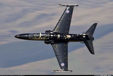
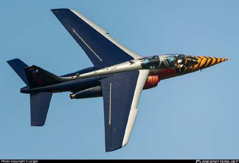
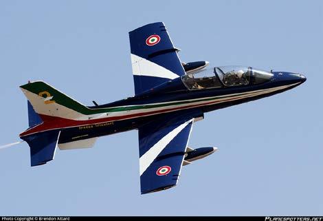
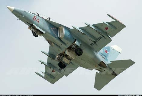
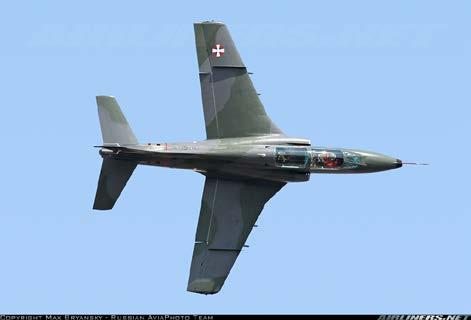
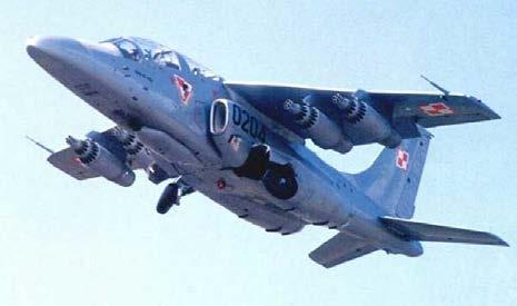
33 Trainers/light attack aircraft Bae Systems Hawk Dassault/Dornier Alpha Jet Aermacchi MB- 339 Yak- 130 Soko G- 4 Super Galeb PZL I- 22 Iryda
34 Specifications of some trainer/light attack aircraft Aircraft Aspect Ratio Maximum Mach Service Range Sea level High altitude Ceiling Alpha Jet?? ,000 ft 2,600 km Hawk 5.3? 1.2 (dive) 44,500 ft 2,520 km Aermacchi? ,000 ft 1,760 km MB- 339 Yak- 130?? ,550 ft 2,100 km Soko G- 4?? ,160 ft 1,900 km Super Galeb PZL I- 22 Iryda?? ,936 ft 1,200 km
Stability and Flight Controls
 Stability and Flight Controls Three Axes of Flight Longitudinal (green) Nose to tail Lateral (blue) Wing tip to Wing tip Vertical (red) Top to bottom Arm Moment Force Controls The Flight Controls Pitch
Aerodynamics Principles
 Aerodynamics Principles Stage 1 Ground Lesson 3 Chapter 3 / Pages 2-18 3:00 Hrs Harold E. Calderon AGI, CFI, CFII, and MEI Lesson Objectives Become familiar with the four forces of flight, aerodynamic
Aero Club. Introduction to Flight
 Aero Club Presents Introduction to RC Modeling Module 1 Introduction to Flight Centre For Innovation IIT Madras Page2 Table of Contents Introduction:... 3 How planes fly How is lift generated?... 3 Forces
ROAD MAP... D-1: Aerodynamics of 3-D Wings D-2: Boundary Layer and Viscous Effects D-3: XFLR (Aerodynamics Analysis Tool)
") Unit D-1: Aerodynamics of 3-D Wings Page 1 of 5 AE301 Aerodynamics I UNIT D: Applied Aerodynamics ROAD MAP... D-1: Aerodynamics of 3-D Wings D-: Boundary Layer and Viscous Effects D-3: XFLR (Aerodynamics
Unit D-1: Aerodynamics of 3-D Wings Page 1 of 5 AE301 Aerodynamics I UNIT D: Applied Aerodynamics ROAD MAP... D-1: Aerodynamics of 3-D Wings D-: Boundary Layer and Viscous Effects D-3: XFLR (Aerodynamics
DIRECCION DE PERSONAL AERONAUTICO DPTO. DE INSTRUCCION PREGUNTAS Y OPCIONES POR TEMA
 MT DIREION DE PERSONL ERONUTIO DPTO. DE INSTRUION PREGUNTS Y OPIONES POR TEM 1 TEM: 0292 FLT/DSP - (HP. 03) ERODYNMIS OD_PREG: PREG20084823 (8324) PREGUNT: When are inboard ailerons normally used? Low-speed
DIRECCION DE PERSONAL AERONAUTICO DPTO. DE INSTRUCCION PREGUNTAS Y OPCIONES POR TEMA
 MT DIREION DE PERSONL ERONUTIO DPTO. DE INSTRUION PREGUNTS Y OPIONES POR TEM 1 TEM: 0114 TP - (HP. 03) ERODYNMIS OD_PREG: PREG20078023 (8358) PREGUNT: What is the safest and most efficient takeoff and
Principles of glider flight
 Principles of glider flight [ Lecture 2: Control and stability ] Richard Lancaster Email: Richard@RJPLancaster.net Twitter: @RJPLancaster ASK-21 illustrations Copyright 1983 Alexander Schleicher GmbH &
Related Careers: Aircraft Instrument Repairer Aircraft Designer Aircraft Engineer Aircraft Electronics Specialist Aircraft Mechanic Pilot US Military
 Airplane Design and Flight Fascination with Flight Objective: 1. You will be able to define the basic terms related to airplane flight. 2. You will test fly your airplane and make adjustments to improve
Flight Control Systems Introduction
 Flight Control Systems Introduction Dr Slide 1 Flight Control System A Flight Control System (FCS) consists of the flight control surfaces, the respective cockpit controls, connecting linkage, and necessary
The subsonic compressibility effect is added by replacing. with
 Swept Wings The main function of a swept wing is to reduce wave drag at transonic and supersonic speeds. Consider a straight wing and a swept wing in a flow with a free-stream velocity V. Assume that the
PEMP ACD2501. M.S. Ramaiah School of Advanced Studies, Bengaluru
 Aircraft Performance, Stability and Control Session delivered by: Mr. Ramjan Pathan 1 Session Objectives Aircraft Performance: Basicsof performance (t (steadystateand tt d accelerated) Performance characteristics
Airframes. Chapter 5: Wings & Tailplane
 Airframes Chapter 5: Wings & Tailplane 1 2 Learning Objectives The purpose of this chapter is to discuss in more detail, 2 of the 4 major components, the Wing (or mainplane) and the Tailplane. By the end
Aircraft Design: A Systems Engineering Approach, M. Sadraey, Wiley, Figures
 Aircraft Design: A Systems Engineering Approach, M. Sadraey, Wiley, 2012 Chapter 5 Wing Design Figures 1 Identify and prioritize wing design requirements (Performance, stability, producibility, operational
Learning Objectives 081 Principles of Flight
 Learning Objectives 081 Principles of Flight Conventions for questions in subject 081. 1. The following standard conventions are used for certain mathematical symbols: * multiplication. > = greater than
Stability & Control Aspects of UCAV Configurations
 Stability & Control Aspects of UCAV Configurations Paul Flux Senior Aerodynamicist BAE SYSTEMS Air Programmes Report Documentation Page Form Approved OMB No. 0704-0188 Public reporting burden for the collection
It should be noted that the symmetrical airfoil at zero lift has no pitching moment about the aerodynamic center because the upper and
 NAVWEPS -81-8 and high power, the dynamic pressure in the shaded area can be much greater than the free stream and this causes considerably greater lift than at zero thrust. At high power conditions the
II.E. Airplane Flight Controls
 References: FAA-H-8083-3; FAA-8083-3-25 Objectives Key Elements Elements Schedule Equipment IP s Actions SP s Actions Completion Standards The student should develop knowledge of the elements related to
PRIMARY FLIGHT CONTROLS. AILERONS Ailerons control roll about the longitudinal axis. The ailerons are attached to the outboard trailing edge of
 Aircraft flight control systems are classified as primary and secondary. The primary control systems consist of those that are required to safely control an airplane during flight. These include the ailerons,
Aerodynamic Terms. Angle of attack is the angle between the relative wind and the wing chord line. [Figure 2-2] Leading edge. Upper camber.
![Aerodynamic Terms. Angle of attack is the angle between the relative wind and the wing chord line. [Figure 2-2] Leading edge. Upper camber.](/thumbs/82/86661300.jpg "Aerodynamic Terms. Angle of attack is the angle between the relative wind and the wing chord line. [Figure 2-2] Leading edge. Upper camber.") Chapters 2 and 3 of the Pilot s Handbook of Aeronautical Knowledge (FAA-H-8083-25) apply to powered parachutes and are a prerequisite to reading this book. This chapter will focus on the aerodynamic fundamentals
Chapters 2 and 3 of the Pilot s Handbook of Aeronautical Knowledge (FAA-H-8083-25) apply to powered parachutes and are a prerequisite to reading this book. This chapter will focus on the aerodynamic fundamentals
Winnipeg Headingley Aero Modellers. Things About Airplanes.
 Winnipeg Headingley Aero Modellers Things About Airplanes. Table of Contents Introduction...2 The Airplane...2 How the Airplane is Controlled...3 How the Airplane Flies...6 Lift...6 Weight...8 Thrust...9
C-130 Reduction in Directional Stability at Low Dynamic Pressure and High Power Settings
 C-130 Reduction in Directional Stability at Low Dynamic Pressure and High Power Settings The C-130 experiences a marked reduction of directional stability at low dynamic pressures, high power settings,
Homework Exercise to prepare for Class #2.
 Homework Exercise to prepare for Class #2. Answer these on notebook paper then correct or improve your answers (using another color) by referring to the answer sheet. 1. Identify the major components depicted
A103 AERODYNAMIC PRINCIPLES
 A103 AERODYNAMIC PRINCIPLES References: FAA-H-8083-25A, Pilot s Handbook of Aeronautical Knowledge, Chapter 3 (pgs 4-10) and Chapter 4 (pgs 1-39) OBJECTIVE: Students will understand the fundamental aerodynamic
Lift for a Finite Wing. all real wings are finite in span (airfoils are considered as infinite in the span)
") Lift for a Finite Wing all real wings are finite in span (airfoils are considered as infinite in the span) The lift coefficient differs from that of an airfoil because there are strong vortices produced
Lift for a Finite Wing all real wings are finite in span (airfoils are considered as infinite in the span) The lift coefficient differs from that of an airfoil because there are strong vortices produced
No Description Direction Source 1. Thrust
 AERODYNAMICS FORCES 1. WORKING TOGETHER Actually Lift Force is not the only force working on the aircraft, during aircraft moving through the air. There are several aerodynamics forces working together
Preliminary Design Review (PDR) Aerodynamics #2 AAE-451 Aircraft Design
 Aerodynamics #2 AAE-451 Aircraft Design") Preliminary Design Review (PDR) Aerodynamics #2 AAE-451 Aircraft Design Aircraft Geometry (highlight any significant revisions since Aerodynamics PDR #1) Airfoil section for wing, vertical and horizontal
Preliminary Design Review (PDR) Aerodynamics #2 AAE-451 Aircraft Design Aircraft Geometry (highlight any significant revisions since Aerodynamics PDR #1) Airfoil section for wing, vertical and horizontal
The canard. Why such a configuration? Credit : Jean-François Edange
 The canard Why such a configuration? Credit : Jean-François Edange N obody doubtless knows that a great majority of light or heavy planes share a common design. Schematically, we find a fuselage, wings
LAPL(A)/PPL(A) question bank FCL.215, FCL.120 Rev PRINCIPLES OF FLIGHT 080
/PPL(A) question bank FCL.215, FCL.120 Rev PRINCIPLES OF FLIGHT 080") PRINCIPLES OF FLIGHT 080 1 Density: Is unaffected by temperature change. Increases with altitude increase. Reduces with temperature reduction. Reduces with altitude increase. 2 The air pressure that acts
PRINCIPLES OF FLIGHT 080 1 Density: Is unaffected by temperature change. Increases with altitude increase. Reduces with temperature reduction. Reduces with altitude increase. 2 The air pressure that acts
The Metric Glider. By Steven A. Bachmeyer. Aerospace Technology Education Series
 The Metric Glider By Steven A. Bachmeyer Aerospace Technology Education Series 10002 Photographs and Illustrations The author wishes to acknowledge the following individuals and organizations for the photographs
XI.C. Power-Off Stalls
 References: FAA-H-8083-3; POH/AFM Objectives Key Elements Elements Schedule Equipment IP s Actions SP s Actions Completion Standards The student should develop knowledge of stalls regarding aerodynamics,
AIRCRAFT PRIMARY CONTROLS A I R C R A F T G E N E R A L K N O W L E D G E
 1.02.02 AIRCRAFT PRIMARY CONTROLS 1. 0 2 A I R C R A F T G E N E R A L K N O W L E D G E CONTROLLING AIRCRAFT AIRCRAFT CONTROL SYSTEM In general, we use control inputs of the following devices in cabin:
X-29 Canard Jet. A Simple Depron Foam Build.
 X-29 Canard Jet. A Simple Depron Foam Build. Two full sized X-29 s were built and the first flew in 1984. They were experimental aircraft, testing this unusual configuration of a canard jet with swept
Low-Speed Wind-Tunnel Investigation of the Stability and Control Characteristics of a Series of Flying Wings With Sweep Angles of 50
 NASA Technical Memorandum 464 Low-Speed Wind-Tunnel Investigation of the Stability and Control Characteristics of a Series of Flying Wings With Sweep Angles of 5 Scott P. Fears Lockheed Engineering & Sciences
IMPACT OF FUSELAGE CROSS SECTION ON THE STABILITY OF A GENERIC FIGHTER
 IMPACT OF FUSELAGE CROSS SECTION ON THE STABILITY OF A GENERIC FIGHTER Robert M. Hall NASA Langley Research Center Hampton, Virginia ABSTRACT Many traditional data bases, which involved smooth-sided forebodies,
Theory of Flight Stalls. References: FTGU pages 18, 35-38
 Theory of Flight 6.07 Stalls References: FTGU pages 18, 35-38 Review 1. What are the two main types of drag? 2. Is it possible to eliminate induced drag? Why or why not? 3. What is one way to increase
AERODYNAMIC CHARACTERISTICS OF SPIN PHENOMENON FOR DELTA WING
 ICAS 2002 CONGRESS AERODYNAMIC CHARACTERISTICS OF SPIN PHENOMENON FOR DELTA WING Yoshiaki NAKAMURA (nakamura@nuae.nagoya-u.ac.jp) Takafumi YAMADA (yamada@nuae.nagoya-u.ac.jp) Department of Aerospace Engineering,
Anna University Regional office Tirunelveli
 Effect of Tubercle Leading Edge Control Surface on the Performance of the Double Delta Wing Fighter Aircraft P Sharmila 1, S Rajakumar 2 1 P.G. Scholar, 2 Assistant Professor, Mechanical Department Anna
Ottawa Remote Control Club Wings Program
 + Ottawa Remote Control Club Wings Program Guide line By Shahram Ghorashi Chief Flying Instructor Table of Contents Rule and regulation Quiz 3 Purpose of the program 4 Theory of flight Thrust 4 Drag 4
Chapter 5 Wing design - selection of wing parameters - 3 Lecture 21 Topics
 Chapter 5 Wing design - selection of wing parameters - 3 Lecture 21 Topics 5.3.2 Choice of sweep ( ) 5.3.3 Choice of taper ratio ( λ ) 5.3.4 Choice of twist ( ε ) 5.3.5 Wing incidence(i w ) 5.3.6 Choice
XI.B. Power-On Stalls
 XI.B. Power-On Stalls References: AC 61-67; FAA-H-8083-3; POH/AFM Objectives Key Elements Elements Schedule Equipment IP s Actions SP s Actions Completion Standards The student should develop knowledge
HIGH ALTITUDE AERODYNAMICS
 HIGH ALTITUDE AERODYNAMICS CRITICAL ASPECTS OF MACH FLIGHT In recent years, a number of corporate jet airplanes have been involved in catastrophic loss of control during high-altitude/high-speed flight.
Aircraft Stability and Control Prof. A. K. Ghosh Department of Aerospace Engineering Indian Institute of Technology-Kanpur. Lecture- 25 Revision
 Aircraft Stability and Control Prof. A. K. Ghosh Department of Aerospace Engineering Indian Institute of Technology-Kanpur Lecture- 25 Revision Yes, dear friends, this is the mann ki baat session for lateral
External Tank- Drag Reduction Methods and Flow Analysis
 External Tank- Drag Reduction Methods and Flow Analysis Shaik Mohammed Anis M.Tech Student, MLR Institute of Technology, Hyderabad, India. G. Parthasarathy Associate Professor, MLR Institute of Technology,
Flying Wings. By Henry Cole
 Flying Wings By Henry Cole FLYING WINGS REPRESENT THE THEORETICAL ULTIMATE IN AIRCRAFT DESIGN. USE THESE IDEAS, AVAILABLE AFTER A YEAR, OF RESEARCH, TO DEVELOP PRACTICAL MODELS. The rubber version of this
PRINCIPLES OF FLIGHT
 CHAPTER 3 PRINCIPLES OF FLIGHT INTRODUCTION Man has always wanted to fly. Legends from the very earliest times bear witness to this wish. Perhaps the most famous of these legends is the Greek myth about
LAPL/PPL question bank FCL.215, FCL.120 Rev PRINCIPLES OF FLIGHT 080
 LAPL/PPL question bank FCL.215, FCL.120 Rev. 1.7 11.10.2018 PRINCIPLES OF FLIGHT 080 1 Density: Reduces with temperature reduction. Increases with altitude increase. Reduces with altitude increase. Is
JAA Administrative & Guidance Material Section Five: Licensing, Part Two: Procedures
 INTRODUCTION Conventions for questions in subject 081. 1. The following standard conventions are used for certain mathematical symbols: * multiplication. >= greater than or equal to.
Aerodynamics. A study guide on aerodynamics for the Piper Archer
 Aerodynamics A study guide on aerodynamics for the Piper Archer Aerodynamics The purpose of this pilot briefing is to discuss the simple and complex aerodynamics of the Piper Archer. Please use the following
air cadet publication
 air cadet publication ACP 33 flight volume 2 - principles of flight No Amendment List Date Amended by Date Incorporated 1 2 3 4 5 6 7 8 9 10 11 12 13 14 15 16 i ACP 33 FLIGHT CONTENTS Volume 1... History
ANALYSIS OF AERODYNAMIC CHARACTERISTICS OF A SUPERCRITICAL AIRFOIL FOR LOW SPEED AIRCRAFT
 ANALYSIS OF AERODYNAMIC CHARACTERISTICS OF A SUPERCRITICAL AIRFOIL FOR LOW SPEED AIRCRAFT P.Sethunathan 1, M.Niventhran 2, V.Siva 2, R.Sadhan Kumar 2 1 Asst.Professor, Department of Aeronautical Engineering,
Aircraft Stability and Performance 2nd Year, Aerospace Engineering. Dr. M. Turner
 Aircraft Stability and Performance 2nd Year, Aerospace Engineering Dr. M. Turner Basic Info Timetable 15.00-16.00 Monday Physics LTA 16.00-17.00 Monday Physics LTA Exam 2 1 2 hour exam 6 questions 2 from
FUSELAGE-MOUNTED FINS ON THE STATIC DIRECTIONAL STABILITY. By M. Leroy Spearman, Ross B. Robinson, and Cornelius Driver
 RESEARCH MEMORANDUM THE EFFECTS OF THE ADDITION OF SMALL FUSELAGE-MOUNTED FINS ON THE STATIC DIRECTIONAL STABILITY CHARACTERISTICS OF A MODEL OF A 45' SWEPT-WING AIRPLANE AT ANGLES OF ATTACK UP TO 15.3?
XI.D. Crossed-Control Stalls
 References: FAA-H-8083-3; POH/AFM Objectives Key Elements Elements Schedule Equipment IP s Actions SP s Actions Completion Standards The student should understand the dynamics of a crossed-control stall
Analysis of the Z-wing configuration
 School of Innovation, Design and Engineering BACHELOR THESIS IN AERONAUTICAL ENGINEERING 15 CREDITS, BASIC LEVEL 300 Analysis of the Z-wing configuration Author: Joakim Avén Report code: MDH.IDT.FLYG.0231.2011.GN300.15HP.Ae
Chapter 3: Aircraft Construction
 Chapter 3: Aircraft Construction p. 1-3 1. Aircraft Design, Certification, and Airworthiness 1.1. Replace the letters A, B, C, and D by the appropriate name of aircraft component A: B: C: D: E: A = Empennage,
Aerobatic Trimming Chart
 Aerobatic Trimming Chart From RCU - Chip Hyde addresses his view of Engine/Motor thrust. I run almost no right thrust in my planes and use the thottle to rudd mix at 2% left rudd. to throttle at idle.
ATPL Principles of Flight - deel 2
 ATPL Principles of Flight - deel 2 1. If flaps are deployed at constant IAS in straight and level flight, the magnitude of tip vortices will eventually: (flap span less then wing span) A decrease B remain
BASIC AIRCRAFT STRUCTURES
 Slide 1 BASIC AIRCRAFT STRUCTURES The basic aircraft structure serves multiple purposes. Such as aircraft aerodynamics; which indicates how smooth the aircraft flies thru the air (The Skelton of the aircraft
Aerodynamics: The Wing Is the Thing
 Page B1 Chapter Two Chapter Two Aerodynamics: The Wing Is the Thing The Wing Is the Thing May the Four Forces Be With You 1. [B1/3/2] The four forces acting on an airplane in flight are A. lift, weight,
Tim Lee s journal publications
 Tim Lee s journal publications 82. Lee, T., and Tremblay-Dionne, V., (2018) Impact of wavelength and amplitude of a wavy ground on a static NACA 0012 airfoil submitted to Journal of Aircraft (paper in
C-1: Aerodynamics of Airfoils 1 C-2: Aerodynamics of Airfoils 2 C-3: Panel Methods C-4: Thin Airfoil Theory
 ROAD MAP... AE301 Aerodynamics I UNIT C: 2-D Airfoils C-1: Aerodynamics of Airfoils 1 C-2: Aerodynamics of Airfoils 2 C-3: Panel Methods C-4: Thin Airfoil Theory AE301 Aerodynamics I : List of Subjects
WHAT IS GLIDER? A light engineless aircraft designed to glide after being towed aloft or launched from a catapult.
 GLIDER BASICS WHAT IS GLIDER? A light engineless aircraft designed to glide after being towed aloft or launched from a catapult. 2 PARTS OF GLIDER A glider can be divided into three main parts: a)fuselage
Uncontrolled copy not subject to amendment. Principles of Flight
 Uncontrolled copy not subject to amendment Principles of Flight Principles of Flight Learning Outcome 2: Understand how the stability of an aeroplane is maintained in flight and how manoeuvrability is
Conceptual Aerodynamic Design of Delta-type Tailless Unmanned Aircraft
 IJUSEng 2014, Vol. 2, No. S2, 1-15 http://dx.doi.org/10.14323/ijuseng.2014.4 Technical Note Conceptual Aerodynamic Design of Delta-type Tailless Unmanned Aircraft Alexander S. Goodman Marques Aviation
V mca (and the conditions that affect it)
") V mca (and the conditions that affect it) V mca, the minimum airspeed at which an airborne multiengine airplane is controllable with an inoperative engine under a standard set of conditions, is arguably
V mca (and the conditions that affect it) V mca, the minimum airspeed at which an airborne multiengine airplane is controllable with an inoperative engine under a standard set of conditions, is arguably
PILOT S HANDBOOK of Aeronautical Knowledge AC61-23C
 PILOT S HANDBOOK of Aeronautical Knowledge AC61-23C Revised 1997 Chapter 1 Excerpt Compliments of... www.alphatrainer.com Toll Free: (877) 542-1112 U.S. DEPARTMENT OF TRANSPORTATION FEDERAL AVIATION ADMINISTRATION
ME 239: Rocket Propulsion. Forces Acting on a Vehicle in an Atmosphere (Follows Section 4.2) J. M. Meyers, PhD
 J. M. Meyers, PhD") ME 239: Rocket Propulsion Forces Acting on a Vehicle in an Atmosphere (Follows Section 4.2) J. M. Meyers, PhD 1 Commonly acting forces on a vehicle flying in a planetary atmosphere: Thrust Aerodynamic
ME 239: Rocket Propulsion Forces Acting on a Vehicle in an Atmosphere (Follows Section 4.2) J. M. Meyers, PhD 1 Commonly acting forces on a vehicle flying in a planetary atmosphere: Thrust Aerodynamic
Flight Corridor. The speed-altitude band where flight sustained by aerodynamic forces is technically possible is called the flight corridor.
 Flight Corridor The speed-altitude band where flight sustained by aerodynamic forces is technically possible is called the flight corridor. The subsonic Boeing 747 and supersonic Concorde have flight corridors
The effect of back spin on a table tennis ball moving in a viscous fluid.
 How can planes fly? The phenomenon of lift can be produced in an ideal (non-viscous) fluid by the addition of a free vortex (circulation) around a cylinder in a rectilinear flow stream. This is known as
HOW AND WHY DO GLIDERS FLY - WHAT SHAPE SHOULD THEY BE?
 HOW AND WHY DO GLIDERS FLY - WHAT SHAPE SHOULD THEY BE? What is flight? We all understand that air is a fluid, not dissimilar to, if lighter than, water, and we can all appreciate that an immerse body
CHAPTER 1 - PRINCIPLES OF FLIGHT
 CHAPTER 1 - PRINCIPLES OF FLIGHT Reilly Burke 2005 INTRODUCTION There are certain laws of nature or physics that apply to any object that is lifted from the Earth and moved through the air. To analyze
POWERED FLIGHT HOVERING FLIGHT
 Once a helicopter leaves the ground, it is acted upon by the four aerodynamic forces. In this chapter, we will examine these forces as they relate to flight maneuvers. POWERED FLIGHT In powered flight
Big News! Dick Kline Inventor of the KF AirFoil Contacts rcfoamfighters.
 Big News! Dick Kline Inventor of the KF AirFoil Contacts rcfoamfighters. (Copy of Email from Dick Kline to rcfoamfighters on 3/28/09) --------------------------------------------------------------------------------
Reduction of Skin Friction Drag in Wings by Employing Riblets
 Reduction of Skin Friction Drag in Wings by Employing Riblets Kousik Kumaar. R 1 Assistant Professor Department of Aeronautical Engineering Nehru Institute of Engineering and Technology Coimbatore, India
Detailed study 3.4 Topic Test Investigations: Flight
 Name: Billanook College Detailed study 3.4 Topic Test Investigations: Flight Ivanhoe Girls Grammar School Questions 1 and 2 relate to the information shown in the diagram in Figure 1. z Question 1 y Figure
LESSONS 1, 2, and 3 PRACTICE EXERCISES
 LESSONS 1, 2, and 3 PRACTICE EXERCISES The following items will test your grasp of the material covered in these lessons. There is only one correct answer for each item. When you complete the exercise,
Flight Controls. Chapter 5. Introduction
 Chapter 5 Flight Controls Introduction This chapter focuses on the flight control systems a pilot uses to control the forces of flight, and the aircraft s direction and attitude. It should be noted that
Aircraft Stability and Control Prof. A.K.Ghosh Department of Aerospace Engineering Indian Institute of Technology-Kanpur. Lecture-01 Introduction
 Aircraft Stability and Control Prof. A.K.Ghosh Department of Aerospace Engineering Indian Institute of Technology-Kanpur Lecture-01 Introduction Wish you all very, very happy New Year. We are on the tarmac
DEFINITIONS. Aerofoil
 Aerofoil DEFINITIONS An aerofoil is a device designed to produce more lift (or thrust) than drag when air flows over it. Angle of Attack This is the angle between the chord line of the aerofoil and the
Gleim Private Pilot Flight Maneuvers Seventh Edition, 1st Printing Updates February 2018
 Page 1 of 11 Gleim Private Pilot Flight Maneuvers Seventh Edition, 1st Printing Updates February 2018 If you are tested on any content not represented in our materials or this update, please share this
THE AIRCRAFT IN FLIGHT Issue /07/12
 1 INTRODUCTION This series of tutorials for the CIX VFR Club are based on real world training. Each document focuses on a small part only of the necessary skills required to fly a light aircraft, and by
A COMPUTATIONAL STUDY ON THE DESIGN OF AIRFOILS FOR A FIXED WING MAV AND THE AERODYNAMIC CHARACTERISTIC OF THE VEHICLE
 28 TH INTERNATIONAL CONGRESS OF THE AERONAUTICAL SCIENCES A COMPUTATIONAL STUDY ON THE DESIGN OF AIRFOILS FOR A FIXED WING MAV AND THE AERODYNAMIC CHARACTERISTIC OF THE VEHICLE Jung-Hyun Kim*, Kyu-Hong
11-1. Horizontal tailplane sizing according to control requirement
 11-1 11 Empennage izing In ection Empennage General Design, the areas of the horizontal and vertical tailplanes were calculated merely with the aid of tail volume coefficients. The tail lever arms were
Jet Propulsion. Lecture-17. Ujjwal K Saha, Ph. D. Department of Mechanical Engineering Indian Institute of Technology Guwahati
 Lecture-17 Prepared under QIP-CD Cell Project Jet Propulsion Ujjwal K Saha, Ph. D. Department of Mechanical Engineering Indian Institute of Technology Guwahati 1 Lift: is used to support the weight of
LEADING-EDGE VORTEX FLAPS FOR SUPERSONIC TRANSPORT CONFIGURATION -EFFECTS OF FLAP CONFIGURATIONS AND ROUNDED LEADING-EDGES-
 ICAS 2002 CONGRESS LEADING-EDGE VORTEX FLAPS FOR SUPERSONIC TRANSPORT CONFIGURATION -EFFECTS OF FLAP CONFIGURATIONS AND ROUNDED LEADING-EDGES- Kenichi RINOIE*, Dong Youn KWAK**, Katsuhiro MIYATA* and Masayoshi
BRONZE LECTURES. Slides on bayriver.co.uk/gliding
 BRONZE LECTURES 2014 Slides on bayriver.co.uk/gliding 1 STUDY Lectures only meant to be a stimulus and provide an opportunity for questions EXAM paper is multi-choice with x sections. 2 READING BOOKS?
FORCES ACTING ON THE AIRPLANE
 CH 03.qxd 10/24/03 6:44 AM Page 3-1 FORCES ACTING ON THE AIRPLANE In some respects at least, how well a pilot performs in flight depends upon the ability to plan and coordinate the use of the power and
Induced Drag Reduction for Modern Aircraft without Increasing the Span of the Wing by Using Winglet
 International Journal of Mechanical & Mechatronics Engineering IJMME-IJENS Vol:10 No:03 49 Induced Drag Reduction for Modern Aircraft without Increasing the Span of the Wing by Using Winglet Mohammad Ilias
The Fly Higher Tutorial IV
 The Fly Higher Tutorial IV THE SCIENCE OF FLIGHT In order for an aircraft to fly we must have two things: 1) Thrust 2) Lift Aerodynamics The Basics Representation of the balance of forces These act against
Bugatti 100P Longitudinal Stick Forces Revision A
 Bugatti 1P Longitudinal Stick Forces Revision A Stick-free static longitudinal stability (stick force-per-knot) and stick-free longitudinal maneuvering stability (stick force-per-g) were computed for the
Aircraft Design Prof. A.K Ghosh Department of Aerospace Engineering Indian Institute of Technology, Kanpur
 Aircraft Design Prof. A.K Ghosh Department of Aerospace Engineering Indian Institute of Technology, Kanpur Lecture - 12 Design Considerations: Aerofoil Selection Good morning friends. The last lecture
Aerodynamic Analysis of Blended Winglet for Low Speed Aircraft
 , July 1-3, 2015, London, U.K. Aerodynamic Analysis of Blended Winglet for Low Speed Aircraft Pooja Pragati, Sudarsan Baskar Abstract This paper provides a practical design of a new concept of massive
The Effect of Canard Configurations to the Aerodynamics of the Blended Wing Body
 Vol:7, No:5, 213 The Effect of Canard Configurations to the Aerodynamics of the Blended Wing Body Zurriati Mohd Ali, Wahyu Kuntjoro, and Wirachman Wisnoe International Science Index, Aerospace and Mechanical
JOURNAL PUBLICATIONS
 1 JOURNAL PUBLICATIONS 71. Lee, T., Mageed, A., Siddiqui, B. and Ko, L.S., (2016) Impact of ground proximity on aerodynamic properties of an unsteady NACA 0012 airfoil, submitted to Journal of Aerospace
EFFECT OF GURNEY FLAPS AND WINGLETS ON THE PERFORMANCE OF THE HAWT
 Chapter-6 EFFECT OF GURNEY FLAPS AND WINGLETS ON THE PERFORMANCE OF THE HAWT 6.1 Introduction The gurney flap (wicker bill) was a small flat tab projecting from the trailing edge of a wing. Typically it
Investigation and Comparison of Airfoils
 AENG 360 Aerodynamics Investigation and Comparison of Airfoils Rocie Benavent Chelseyann Bipat Brandon Gilyard Julian Marcon New York Institute of Technology Fall 2013 2 Executive Summary Airfoil design
Aircraft - Very Heavy Lift at Very Low Cost
 Aircraft - Very Heavy Lift at Very Low Cost Stephen Funck This is a span loader for standard shipping containers. The design goal is the lowest cost per ton / mile. Low wing loading allows for low flight
THE ELEMENTS OF TAILLESS AIRPLANE DESIGN
 THE ELEMENTS OF TAILLESS AIRPLANE DESIGN By A. A. Backstrom (EAA 1162) Rt.l Frisco, TX 75034 J. HERE HAS BEEN over the years a tendency to classify tailless airplane design as an area of mystique practiced
AF101 to AF109. Subsonic Wind Tunnel Models AERODYNAMICS. A selection of optional models for use with TecQuipment s Subsonic Wind Tunnel (AF100)
") Page 1 of 4 A selection of optional models for use with TecQuipment s Subsonic Wind Tunnel (AF100) Dimpled Sphere Drag Model (from AF109) shown inside the TecQuipment AF100 Wind Tunnel. Cylinder, aerofoils,
Page 1 of 4 A selection of optional models for use with TecQuipment s Subsonic Wind Tunnel (AF100) Dimpled Sphere Drag Model (from AF109) shown inside the TecQuipment AF100 Wind Tunnel. Cylinder, aerofoils,
Basic Fluid Mechanics
 Basic Fluid Mechanics Chapter 7B: Forces on Submerged Bodies 7/26/2018 C7B: Forces on Submerged Bodies 1 Forces on Submerged Bodies Lift and Drag are forces exerted on an immersed body by the surrounding