STABILITY INFORMATION BOOKLET REGINA LASKA. Category 1 under MGN 280 (M) with up to 6 persons on board. Document Ref: YPDS/RL/
|
|
|
- Cody Lane
- 5 years ago
- Views:
Transcription
 1489-583346 Eail. info@yacht-designer.")
1 STABILITY INFORMATION BOOKLET REGINA LASKA Category 1 under MGN 280 (M) with up to 6 persons on board Approval Stap Docuent Ref: YPDS/RL/ th June 2013 Stuart M Roy, Naval Architect Yacht & Powercraft Design Services Ltd 9 Upper Spinney, Warsash, Southapton, SO31 9JW Tel. 44 (0) Eail. info@yacht-designer.co.uk
2 Contents Page No. General Particulars... 2 Arrangeent of Sections.. 3 Section 1: Operational Inforation... 4 Arrangeent of Tanks and Ballast... 5 Sail Plan... 6 Angles of Deck Edge Iersion and Downflooding. 7 Notes on Stability for the Guidance of the Master... 8 Maxiu Steady Heel Angle to Prevent Downflooding in Gusts.. 9 Curves of Maxiu Steady Heel Angle to Prevent Downflooding in Squalls.. 10 Exaples Showing the Use of the Maxiu Steady Heel Angle Curves 11 Section 2: Technical Data and Loading Conditions.. 12 Freeboard Marks Tank Capacities. 13 Loading Condition 1 - Depart Port Stability Curve for Condition 1 15 Stability Data for Condition Loading Condition 2 - Arrive Destination Stability Curve for Condition 2 18 Stability Data for Condition Section 3: Reference Inforation Hydrostatic Curves & Tabulated Data Cross Curves & Tabulated Data. 24 Notes on the Use of Cross Curves.. 27 Inclining Experient & Lightship Deterination. 28 Tank Calibrations.. 31 Notes on the Use of Free Surface Moents.. 36 Appendices: 1. Beaufort Scales of Wind Speeds and Corresponding Pressures Metric/Iperial Conversions Calculation Software Details
3 General Particulars Vessel s Nae: REGINA LASKA Class: Hallberg-Rassy 46 HIN Nuber: Official Nuber: Port of Registry: Owner s Nae Owner s Address: Builder: SE-HRM-46099L697 TBA Lerwick Karolina Örn Schulz and Leon Schulz High Ridge 43, Triq F. Vidal Ibragg, SWQ 2472 Malta E-ail: leon@reginasailing.co Phone: Mob: Hallberg-Rassy S Ellös Sweden Date of Construction: 1997 Classification Society: Geranischer Lloyd 100 A5 Diensions (taken fro Designer s Lines Plan): Length Overall: Length BP: Maxiu Bea: Depth aidships to u/s of bulwark capping Displaceent Fully Laden: Draught Fully Laden: Miniu Freeboard aidships to u/s capping: Gross Tonnage (if registered): kg TBA tonnes Area of operation: MCA Category 1 Up to 150 iles fro a safe haven Standard of Survivability: Intact Stability only Maxiu Nuber of persons on board: 6 (when in coercial use) 2
4 Arrangeent of Sections This booklet is arranged in sections so that the ost essential ites are brought to the user s attention first. Section 1 Operational Inforation This section contains guidance intended to ensure that the level of stability ay be judged with reference to a recoended axiu steady angle of heel to prevent downflooding in gusts and squalls. Section 2 Technical Data and Loading Conditions This section shows detailed loading conditions upon which the recoended heeling angles are based. Section 3 Reference Inforation This section contains basic inforation, which is necessary for the calculations in Sections 1 and 2. Appendices It is not necessary for the skipper to refer to this part except that the Beaufort Scale and the etric/iperial conversion table ay be found to be useful. 3
5 SECTION 1 Operational Inforation 4
6 Arrangeent of Tanks and Ballast Tankage and Ballast No. Ite Aount Units 1 FW Tank 920 litres 2 Fuel Tank 660 litres 3 Hot Water Tank 40 litres 4 Sewage Holding Tank Fwd Heads 57 litres 5 Sewage Holding Tank Aft Heads 57 litres 6 Fixed Ballast 6.6 tonnes Datu Positions Draughts are referred to the Baseline (USK). All other vertical locations are also referred to the Baseline. All longitudinal locations are referred to the FP, aft Ste, positive forward, negative aft. FP is at the intersection of the bow and DWL. The DWL is parallel to the base at above. AP is at the intersection of the underside of the hull aft and the DWL. Tri is defined as: Draught Aft Draught Forward Design Tri = rake of keel = zero. 5
7 Sail Plan Ref. Sail Area ( 2 ) Height of Centroid above BASE () M Full Mainsail M1 Main Reef M2 Main Reef M3 Main Reef G Full Genoa G1 Genoa Reef G2 Genoa Reef G3 Genoa Reef S Staysail SS Stor Staysail Note: This yacht has in-ast roller furling for the ainsail and roller furling for the genoa, aking the sail areas infinitely variable to suit the conditions. The Sail Plan shows typical exaples of the sail sets that could be used. 6
8 Angles of Deck Edge Iersion and Downflooding No. DESCRIPTION AREA OF CLEAR OPENING ANGLES OF IMMERSION (deg.) ANGLES OF IMMERSION (deg.) c 2 100% Consuables 10% Consuables 1 Deck Edge at aft FP 2 Copanionway Hatch * Forward Edge 3 Copanionway Door Botto of Sill 4 Engine Air Intakes 10.5 N/A N/A Critical downflooding is deeed to occur when the lower edges of openings having an aggregate area (in 2 ) greater than: displaceent (in tonnes) /1500 are iersed. i.e. departure /1500 = = 139 c 2 arrival /1500 = = 129 c 2 Thus ite 4 in the list above is not regarded as critical and it is the iersion of the Copanionway Hatch Forward Top Edge (ite 2 above * ) which defines the critical downflooding angles referred to in this booklet. The aster should note that the presence of the vents as listed above significantly reduces the ability of this vessel to withstand downflooding and with these openings securely closed the safety of the vessel is enhanced considerably. While the engine air inlet needs to reain open, any extractor vents fro the galley, accoodation and the heads copartents should be closed at sea, except in the ost settled conditions. Also please note: All opening portlights and hatches should be closed and locked at sea. 7
9 Notes on Stability for the Guidance of the Master 1. The stability characteristics of this vessel qualify it for operation in Category 1 with up to 6 persons on board. This category is defined as Up to 150 iles fro a Safe Haven. 2. Copliance with the stability criteria indicated in this booklet does not ensure iunity against capsizing regardless of the circustances or absolve the aster fro his responsibilities. Masters should therefore exercise prudence and good seaanship having regard to the season of the year, experience of the crew, weather forecasts and navigational zone, and should take appropriate action as to the speed, course and sail setting warranted by the prevailing conditions. 3. Before a voyage coences care should be taken to ensure that sizeable ites of equipent have been properly stowed to iniize the possibility of both longitudinal and transverse shifting under the effect of accelerations caused by pitching and rolling, or in the event of a knockdown to 90 degrees. 4. In adverse weather conditions and when there is the possibility of encountering a severe gust, squall or large breaking wave, all exposed doors, hatches, skylights, vents, etc. should be closed and securely fastened to prevent the ingress of water. Stor boards etc. should be erected and fitted. 5. The aount of sail carried is at the discretion of the Master and his decision will have to take into account any factors. In assessing the risks of downflooding, the Master should be guided by Figures 1 and a) Figure 1 shows the axiu recoended steady heel angle to prevent downflooding in gusts. Operation of the vessel at a greater heel angle would result in downflooding if it were to encounter the strongest possible gust in the prevailing turbulent airstrea, which could exert a heeling oent equal to twice that of the ean wind. b) Figure 2 shows the axiu recoended steady heel angle to prevent downflooding in squalls. Operation of the vessel at a greater heel angle would result in downflooding if it were to encounter the heeling effects of a squall arising fro a stor cell or frontal syste which ay result in a heeling oent any ties greater than that of the ean wind. For this reason the Master should have regard to the axiu steady heel angle curves presented for a range of squall speeds. 7. By using the readings fro his inclinoeter and aneoeter a Master is able to deterine the degree of risk of capsize in gusts or squalls which ay occur in the prevailing weather syste. He ay then decide to shorten sail together with other actions he considers necessary. 8. Additional care should be taken when sailing with the wind fro astern as, in the event of the vessel broaching or a gust striking the vessel on the bea, the heeling effects of the wind ay be increased to a dangerous level when the preceding heel angle was sall. 8
10 ` MCA Stability Inforation Booklet Maxiu Steady Heel Angle to Prevent Downflooding in Gusts Angle of equilibriu - derived wind heeling ar (gust) GZ Angle of equilibriu - derived wind heeling ar (steady) Max GZ = at 76.4 deg. Hatch Fwd Top S = 109 deg GZ f Heel to Starboard deg. Maxiu recoended steady heel angle 39.5 degrees Figure 1 GUSTING CONDITIONS When sailing in a steady wind the vessel heels to the angle at which the heeling ar curve intersects the GZ curve. When struck by a gust the heel angle will increase to the intersection of the gust heeling ar curve with the GZ curve. The heeling oent increases in proportion to the square of the apparent wind speed. Operation of the vessel at a ean heel angle not greater than 39.5 degrees ensures significant downflooding openings would not be iersed if it were to encounter the strongest gust in the prevailing turbulent airstrea which could exert a heeling oent equal to twice that of the ean wind. i.e. ean apparent wind has increased in velocity by 1.4. Note: The 100% consuables (Departure) condition is shown above, as it is the slightly ore onerous one. 9
11 Curves of Maxiu Steady Heel Angle to Prevent Downflooding in Squalls Figure 2 SQUALL CONDITIONS Curves of axiu steady heel angle indicate the range of ean or steady heel angles beyond which the vessel will suffer downflooding in the event of a squall. Operation of the vessel in cyclonic conditions particularly in the hours of darkness, where severe squalls are iinent requires the recoended axiu steady heel angle to be reduced depending on the ean apparent wind speed in accordance with the curves presented above. 10
12 Exaples showing the use of the Maxiu Steady Heel Angle Curves Exaple A The yacht is reaching, with a steady apparent wind speed of 13 knots. The ean heel angle is 15 degrees. Forecasts and visible cuulo-nibus clouds suggest squalls ay be iinent. By plotting the heel angle and wind speed (point A in diagra above) the indication is that the vessel will be in danger of heeling to the downflooding angle in squalls of 30 knots. In order to increase safety fro downflooding, say, to withstand squalls of up to 45 knots, sails should be handed or reefed to reduce the ean heel angle to 6.4 degrees (point A above) or less. Exaple B The yacht is beating in gusty conditions with a ean apparent wind speed of 27 knots. The ean heel angle is 20 degrees. No squalls are expected. The heel angle is significantly less than 39.5 degrees, the axiu recoended steady heel angle, and there is therefore a good safety argin against downflooding in a strong gust. Plotting these values of wind speed and heel angle (point B above) also indicates that the vessel would not be vulnerable to downflooding in a squall unless it resulted in a wind speed in excess of about 50 knots. There is thus no need to reduce sail area on the grounds of stability. 11
13 SECTION 2 Technical Data and Loading Conditions 12
14 Freeboard Mark Depth fro underside of keel to top of ain deck aidships (LBP/2) Maxiu fully laden draught aidships (LBP/2) Miniu freeboard aidships (LBP/2) A Freeboard Mark, with diensions 300*25, is on the side of the hull at aidships, with the top of the ark at below the underside of the teak capping, as shown in the following diagra: Tank Capacities For locations, see diagra on page 5. For calibration tables see Section 3. No. TANK Capacity 3 Weight kg LCG fro Ste () VCG above BASE () Max. FSM kg. 1 FW Tank Fuel Tank Hot Water Tank Sewage Holding Tank Fwd Heads 5 Sewage Holding Tank Aft Heads
15 Condition 1 - Depart Port, 100% Consuables Daage Case - Intact Free to Tri Specific Gravity = Fluid analysis ethod: Use corrected VCG Ite Nae Quantity Unit Mass Total Mass Long. Ar Trans. Ar Vert. Ar Total FSM FSM Type kg kg kg..fixed Ites Coplete Yacht - Unladen User Specified Lead Ballast 100% User Specified Total Fixed Ites Tankage Fuel Tank 96% Maxiu FW Tank 96% Maxiu Hot Water Tank 100% Maxiu Fwd Sewage Tank 10% Maxiu Aft Sewage Tank 10% Maxiu Total Tanks 90.18% Load Ites when on Charter Skipper and Crew User Specified Personal Luggage User Specified Stores User Specified Bottled Drinks User Specified Dinghy User Specified Additional Gear User Specified Total Load Ites Total Loadcase FS correction VCG fluid Draught Aft Draught Forward Mean Draught Tri GM Solid GM Fluid by the stern N.B. As the tank volues are not syetrical about the centreline of the vessel (due to the hot water and sewage tanks on the starboard side) there is a sall difference between the port and starboard stability characteristics. As heeling to starboard gives the ost onerous situation, the Loading Conditions presented in this booklet are for the vessel heeled to STARBOARD. 14
16 Stability Curve for Condition Angle of equilibriu - derived wind heeling ar (gust) GZ Angle of equilibriu - derived wind heeling ar (steady) Max GZ = at 76.4 deg. Hatch Fwd Top S = 109 deg Max. Recoended Steady Heel Angle Heel to Starboard deg. Range of stability Critical downflooding angle Maxiu recoended steady heel angle degrees (Required: > degrees) degrees (Required: > 60 degrees) 39.5 degrees (Required: > 15 degrees) Stability Data for Condition 1 Heel to Starboard (deg) GZ Area under GZ curve.rad Displaceent kg Draft at FP n/a Draft at AP n/a Tri (+ve by stern) n/a WL Length Bea ax extents on WL Wetted Area ^ Waterpl. Area ^ Prisatic coeff. (Cp) Block coeff. (Cb) LCB fro zero pt. (+ve fwd) LCF fro zero pt. (+ve fwd) Max deck inclination deg Tri angle (+ve by stern) deg Stability Data for heel angles degrees follow on next page: 15
17 Heel to Starboard (deg) GZ Area under GZ curve fro zero heel.rad Displaceent kg Draft at FP Draft at AP Tri (+ve by stern) WL Length Bea ax extents on WL Wetted Area ^ Waterpl. Area ^ Prisatic coeff. (Cp) Block coeff. (Cb) LCB fro zero pt. (+ve fwd) LCF fro zero pt. (+ve fwd) Max deck inclination deg Tri angle (+ve by stern) deg Key Points Key point Type Iersion angle Eergence angle deg deg Margin Line (iersion pos = ) 29.1 n/a Deck Edge (iersion pos = ) 31.1 n/a Hatch Fwd Top S Downflooding point Hatch Fwd Top P Downflooding point Copanionway Sill S Downflooding point Copanionway Sill P Downflooding point
18 Condition 2 - Arrive Destination, 10% Consuables Daage Case - Intact Free to Tri Specific Gravity = Fluid analysis ethod: Use corrected VCG Ite Nae Quantity Unit Mass Total Mass Long. Ar Trans. Ar Vert. Ar Total FSM FSM Type kg kg kg..fixed Ites Coplete Yacht - Unladen User Specified Lead Ballast 100% Maxiu Total Fixed Ites Tankage Fuel Tank 10% Actual FW Tank 10% Actual Hot Water Tank 100% Actual Fwd Sewage Tank 96% Actual Aft Sewage Tank 96% Actual Total Tanks 18.13% Load Ites when on Charter Skipper and Crew User Specified Personal Luggage User Specified Stores User Specified Bottled Drinks User Specified Dinghy User Specified Additional Gear User Specified Total Load Ites Total Loadcase FS correction VCG fluid Draught Aft Draught Forward Mean Draught Tri GM Solid GM Fluid by the stern
19 Stability Curve for Condition Angle of equilibriu - derived wind heeling ar (gust) G Z Angle of equilibriu - derived wind heeling ar (steady) Max GZ = at 74.5 deg. Hatch Fwd Top S = deg Max. Recoended Steady Heel Angle Heel to Starboard deg. Range of stability Critical downflooding angle Maxiu recoended steady heel angle degrees (Required: > degrees) degrees (Required: > 60 degrees) 39.9 degrees (Required: > 15 degrees) Stability Data for Condition 2 Heel to Starboard (deg) GZ Area under GZ curve.rad Displaceent kg Draft at FP n/a Draft at AP n/a Tri (+ve by stern) n/a WL Length Bea ax extents on WL Wetted Area ^ Waterpl. Area ^ Prisatic coeff. (Cp) Block coeff. (Cb) LCB fro zero pt. (+ve fwd) LCF fro zero pt. (+ve fwd) Max deck inclination deg Tri angle (+ve by stern) deg Stability Data for heel angles degrees follow on next page: 18
20 Heel to Starboard (deg) GZ Area under GZ curve fro zero heel.rad Displaceent kg Draft at FP Draft at AP Tri (+ve by stern) WL Length Bea ax extents on WL Wetted Area ^ Waterpl. Area ^ Prisatic coeff. (Cp) Block coeff. (Cb) LCB fro zero pt. (+ve fwd) LCF fro zero pt. (+ve fwd) Max deck inclination deg Tri angle (+ve by stern) deg Key Points Key point Type Iersion angle Eergence angle deg deg Margin Line (iersion pos = ) 30.3 n/a Deck Edge (iersion pos = ) 32.4 n/a Hatch Fwd Top S Downflooding point Hatch Fwd Top P Downflooding point Copanionway Sill S Downflooding point Copanionway Sill P Downflooding point
21 SECTION 3 Reference Inforation 20
22 Hydrostatic Curves & Data S.G. = K is at under side of keel aidships. Draught is to underside of keel aidships. 1. Level Tri: Fixed Tri = 0 (+ve by stern) MTc 2.13 Iersion (TPc) KML Draft 2.1 KMt 2.07 KB 2.04 LCF LCB 2.01 Displaceent Displaceent kg Long. centre fro zero pt. (+ve fwd) KB KM trans KM long Iersion tonne/c Moent to tri tonne. Draught Aidships Displaceent kg Wetted Area ^ Waterpl. Area ^ LCB fro zero pt. (+ve fwd) LCF fro zero pt. (+ve fwd) KB BMt BML GMt GML KMt KML Iersion (TPc) tonne/c MTc tonne
23 Hydrostatic Curves & Data (cont.) S.G. = K is at under side of keel aidships. Draught is to underside of keel aidships. 2. Tri by the Stern: Fixed Tri = 0.3 (+ve by stern) MTc 2.13 Iersion (TPc) KML Draft 2.1 KMt 2.07 KB 2.04 LCF LCB 2.01 Displaceent Displaceent kg Long. centre fro zero pt. (+ve fwd) KB KM trans KM long Iersion tonne/c Moent to tri tonne. Draught Aidships Displaceent kg Wetted Area ^ Waterpl. Area ^ LCB fro zero pt. (+ve fwd) LCF fro zero pt. (+ve fwd) KB BMt BML GMt GML KMt KML Iersion (TPc) tonne/c MTc tonne
24 Hydrostatic Curves & Data (cont.) S.G. = K is at under side of keel aidships. Draught is to underside of keel aidships. 3. Tri by the Bow: Fixed Tri = -0.3 (-ve by the bow) MTc 2.13 Iersion (TPc) KML Draft 2.1 KMt 2.07 KB 2.04 LCF LCB 2.01 Displaceent Displaceent kg Long. centre fro zero pt. (+ve fwd) KB KM trans KM long Iersion tonne/c Moent to tri tonne. Draught Aidships Displaceent kg Wetted Area ^ Waterpl. Area ^ LCB fro zero pt. (+ve fwd) LCF fro zero pt. (+ve fwd) KB BMt BML GMt GML KMt KML Iersion (TPc) tonne/c MTc tonne
25 Cross Curves and Tabulated Data Specific gravity = 1.025; (Density = 1025 kg/^3); VCG = 0 ; TCG = 0 1. Level Tri: Fixed Tri = 0 (+ve by stern) deg. 80 deg. 90 deg. 60 deg. 100 deg. 50 deg. 110 deg deg. 120 deg deg. 130 deg deg deg deg. 140 deg. 150 deg. 160 deg. 170 deg. 180 deg Displaceent (intact) kg Displaceent (intact) kg 10.0 deg deg deg deg deg deg deg deg deg Displaceent (intact) kg deg deg deg deg deg deg deg deg deg
26 Cross Curves and Tabulated Data (cont.) Specific gravity = 1.025; (Density = 1025 kg/^3); VCG = 0 ; TCG = 0 2. Tri by the Stern: Fixed Tri = 0.3 (+ve by stern) deg. 80 deg. 90 deg. 60 deg. 100 deg. 50 deg. 110 deg deg. 120 deg deg. 130 deg deg deg deg. 140 deg. 150 deg. 160 deg. 170 deg. 180 deg Displaceent (intact) kg Displaceent (intact) kg 10.0 deg deg deg deg deg deg deg deg deg Displaceent (intact) kg deg deg deg deg deg deg deg deg deg
27 Cross Curves and Tabulated Data (cont.) Specific gravity = 1.025; (Density = 1025 kg/^3); VCG = 0 ; TCG = 0 3. Tri by the Bow: Fixed Tri = -0.3 (-ve by the bow) deg. 70 deg. 90 deg. 60 deg. 100 deg. 50 deg. 110 deg deg. 30 deg. 120 deg. 130 deg deg deg deg. 140 deg. 150 deg. 160 deg. 170 deg. 180 deg Displaceent (intact) kg Displaceent (intact) kg 10.0 deg deg deg deg deg deg deg deg deg Displaceent (intact) kg deg deg deg deg deg deg deg deg deg
 are assued to be watertight at all angles of heel. The ast has not been included.")
28 Notes on the Use of Cross Curves curves for displaceents of to kg are presented for angles of heel at intervals between 10 and 180 degrees. The hull, ain deck, superstructure, coachroof and enclosed deck structures (see Figure 1 below) are assued to be watertight at all angles of heel. The ast has not been included. To obtain righting ar (GZ) curves at a given displaceent, the following equation should be used: GZ = - KG x sin(heel angle) (See Figure 2 below) This enables the value of GZ to be calculated at each of the heel angles presented, and subsequently plotted as in the loading conditions presented herein. Figure 1 Figure 2 27
29 Inclining Experient & Lightship Deterination (Worksheet) 28
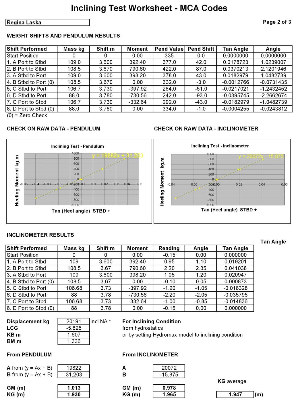
30 29
31 Flotation Data for Inclining Test Draft Aidships Displaceent kg Heel deg -0.2 Draft at FP Draft at AP Draft at LCF Tri (+ve by stern) WL Length Bea ax extents on WL Bea on WL of station with ax area Iersed depth aidships Wetted Area ^ Waterpl. Area ^ LCB fro zero pt. (+ve fwd) LCF fro zero pt. (+ve fwd) Iersion (TPc) tonne/c MTc tonne RM at 1deg = GMt.Disp.sin(1) kg Max deck inclination deg Tri angle (+ve by stern) deg
32 Tank Calibrations 1. FW Tank Fluid Type = Fresh Water Specific gravity = 1 Pereability = 95 % Tri = 0 (+ve by stern) FW Tank % Full LCG Capacity Ullage Sounding Soundings & Ullage Capacity kg Centre of Gravity Free Surface Moent kg. TCG FSM VCG Sounding Ullage % Full Capacity ^3 Capacity kg LCG TCG VCG FSM kg
33 2. Fuel Tank Fluid Type = Diesel Specific gravity = 0.84 Pereability = 95 % Tri = 0 (+ve by stern) ` Fuel Tank % Full TCG LCG 40 Capacity 30 Ullage 20 Sounding 10 FSM VCG Soundings & Ullage Capacity kg Centre of Gravity Free Surface Moent kg. Sounding Ullage % Full Capacity ^3 Capacity kg LCG TCG VCG FSM kg
34 3. Hot Water Tank Fluid Type = Fresh Water Specific gravity = 1 Pereability = 95 % Tri = 0 (+ve by stern) Hot Water Tank % Full 100 FSM 80 VCG 60 TCG LCG 40 Capacity 20 Ullage Sounding Soundings & Ullage Capacity kg Centre of Gravity Free Surface Moent kg. Sounding Ullage % Full Capacity ^3 Capacity kg LCG TCG VCG FSM kg
35 4. Sewage Holding Tank Fwd Heads Fluid Type = Sewage Specific gravity = 1 Pereability = 95 % Tri = 0 (+ve by stern) Fwd Sewage Tank % Full LCG 40 Capacity Ullage 20 Sounding FSM VCG TCG Soundings & Ullage Capacity kg Centre of Gravity Free Surface Moent kg. Sounding Ullage % Full Capacity ^3 Capacity kg LCG TCG VCG FSM kg
36 5. Sewage Holding Tank Aft Heads Fluid Type = Sewage Specific gravity = 1 Pereability = 95 % Tri = 0 (+ve by stern) Aft Sewage Tank % Full 100 FSM 80 VCG 60 TCG LCG 40 Capacity 20 Ullage Sounding Soundings & Ullage Capacity kg Centre of Gravity Free Surface Moent kg. Sounding Ullage % Full Capacity ^3 Capacity kg LCG TCG VCG FSM kg
37 Notes on the Use of Free Surface Moents Provided a tank is copletely filled with liquid no oveent of the liquid is possible and the effect on the ship s stability is precisely the sae as if the tank contained solid aterial. Iediately a quantity of liquid is withdrawn fro the tank the situation changes copletely and the stability of the ship is adversely affected by what is known as a free surface effect. This adverse effect on the stability is referred to as a loss in GM or as a virtual rise in VCG and is calculated as follows: Loss in GM due to = Free Surface Inertia ( 4 ) x Density of Liquid in Tank (Tonnes/ 3 ) Free Surface Effect Displaceent of Vessel (Tonnes) = Free Surface Moent (Tonne.) Displaceent of Vessel (Tonnes) The free surface oents listed in the Tank Capacities Table refer to isolated tanks. If tanks are cross-coupled the free surface oents will be considerably greater. Cross connection valves should therefore reain closed when the vessel is at sea. 36
38 APPENDICES 37
39 Appendix 1 Beaufort Scale of Wind Speeds and Corresponding Pressures Beaufort General Liits of Pressure Nuber Description Speed in Knots kg. per sq. etre 1 Light Air 1 to Light Breeze 4 to Gentle Breeze 7 to Moderate Breeze 11 to Fresh Breeze 17 to Strong Breeze 22 to Near Gale 28 to Gale 34 to Strong Gale 41 to Stor 48 to Violent Stor 56 to Hurricane 64 and over 68 and over 38
40 Appendix 2 Metric/Iperial Conversion Unit Conversion Tables MULTIPLY BY TO CONVERT FROM TO OBTAIN inches c inches feet kg lbs kg Tons (2240 lbs) Tonnes (1000 KG) Tons (2240 lbs) Tonnes per c Tons per inch Tonnes etres units (MCTC) Ton feet units (MCTI) Metre Radians Foot Deg MULTIPLY BY TO CONVERT FROM TO OBTAIN 25.4 inches 2.54 inches c feet lbs kg Tons (2240 lbs) kg Tons (2240 lbs) Tonnes (1000 KG) Tons per inch Tonnes per c Ton feet units (MCTI) Tonnes etres units (MCTC) Foot Deg Metre Radians 10 cubed = 1 cubic centietre 1 cubic centietre F.W. S.G. 1.0 = 1 grae 1000 cubic centietres F.W. S.G. 1.0 = 1 kilograe 1 cubic etre F.W. S.G. 1.0 = 1 tonne (1000 kilos) 1 cubic etre S.W. S.G = tonnes 1 tonne S.W. S.G = cubic etres 1 cubic etre = cubic feet 1 cubic foot = cubic etres 39

41 Appendix 3 Software Version and Settings The data and plots for this vessel were calculated using the following software: Maxsurf Stability Advanced 18.02, build: 22 Model file: C:\Docuents and Settings\Owner\My Docuents\Leon Schulz HR46\Maxsurf and Stability\HR46 - Stability Model Highest precision: Triing: Skin thickness: 509 sections on applied. Longitudinal datu: User defined at FP, aft Ste Vertical datu: Baseline, at USK projected. Analysis tolerance - ideal (worst case): Disp.%: (0.100) Tri% (LCG-TCG): (0.100) Heel% (LCG-TCG): (0.100) 3D Stability Model: 40
Stability Information Booklet. Priority Pontoon
 Stability Information Booklet Priority Pontoon Lightship Index General Particulars...3 General Details...4 Plan - GA...5 Plan - Frames...6 General Precautions against capsizing...7 Special Notes Regarding
Report on inclining test and light ship survey
 Report 79 Report on inclining test and light ship survey Nae of ship (Yard no. and yard): Signal letters: Carried out, place and date: Suary of results: Light ship weight: tonnes Vertical centre of gravity,
CLASS 1E 8 SMOOTH WATERS OPERATIONS 8
 Table of Contents INSTRUCTION TO MASTERS SAFETY INFORMATION 3 STABILITY BOOK TO BE KEPT ON VESSEL 3 LOADING CONDITIONS 3 ASPECTS OF LOADING 3 PASSENGER PARTICULARS 3 HYDROSTATIC AND KN VALUES 4 EXCESS
Trim and Stability Report for M.V. Storm Warning
 Pacific Motor Boat Design/R. W. Etsell, P.E. Naval Architecture and Marine Engineering Trim and Stability Report for M.V. Storm Warning for Kimberlin s Water Taxi Valdez, Alaska Prepared by Richard W.
S0300-A6-MAN-010 CHAPTER 2 STABILITY
 CHAPTER 2 STABILITY 2-1 INTRODUCTION This chapter discusses the stability of intact ships and how basic stability calculations are made. Definitions of the state of equilibrium and the quality of stability
ANNEX 5 IMO MARINE CASULATY AND INCIDENT REPORT DAMAGE CARDS* AND INTACT STABILITY CASUALTY RECORDS
 ANNEX 5 IMO MARINE CASUATY AND INCIDENT REPORT DAMAGE CARDS* AND INTACT STABIITY CASUATY RECORDS Statistics of damaged ships and of intact stability casualties are important to the work of the Organization
OFFSHORE RACING CONGRESS World Leader in Rating Technology
 OFFSHORE RACING CONGRESS World Leader in Rating Technology ORC SY MEASUREMENT GUIDANCE 2017 1. INTRODUCTION This paper must be taken as guidance for the process of boat measurement to allow for the issuance
Chapter 3 Hydrostatics and Floatation
 Chapter 3 Hydrostatics and Floatation Naval Architecture Notes 3.1 Archimedes Law of Floatation Archimedes (born 287 B.C) Law states that An object immersed in a liquid experience a lift equivalent to
MSC Guidelines for Review of Stability for Sailing Catamaran Small Passenger Vessels (T)
") K.B. FERRIE, CDR, Chief, Hull Division References: a. 46 CFR Subchapter T, Parts 178, 179 b. 46 CFR Subchapter S, Parts 170, 171 c. Marine Safety Manual (MSM), Vol. IV d. Navigation and Vessel Circular
K.B. FERRIE, CDR, Chief, Hull Division References: a. 46 CFR Subchapter T, Parts 178, 179 b. 46 CFR Subchapter S, Parts 170, 171 c. Marine Safety Manual (MSM), Vol. IV d. Navigation and Vessel Circular
G.L.M. : the on-board stability calculator... DEMONSTRATION OPERATOR S MANUAL
 General Load Monitor G.L.M. : the on-board stability calculator... DEMONSTRATION OPERATOR S MANUAL Distributed by: DESIGN SYSTEMS & TECHNOLOGIES 150 Rue de Goa, 06600 Antibes, France tel +33.4.92 91 13
Ship Stability. Ch. 8 Curves of Stability and Stability Criteria. Spring Myung-Il Roh
 Lecture Note of Naval Architectural Calculation Ship Stability Ch. 8 Curves of Stability and Stability Criteria Spring 2016 Myung-Il Roh Department of Naval Architecture and Ocean Engineering Seoul National
National Maritime Center
 National Maritime Center Providing Credentials to Mariners (Sample Examination) Page 1 of 7 Choose the best answer to the following Multiple Choice Questions. 1. The sailing drafts are: FWD 14'-08", AFT
SEMI-SUBMERSIBLE YACHT CONCEPT RETHINKING BEHAVIOUR AT ANCHOR AND GENESIS OF THE COMFORT DRAFT
 24th International HISWA Syposiu on Yacht Design and Yacht Construction 14 and 15 Noveber 2016, Asterda, The Netherlands, Asterda RAI Convention Centre SEMI-SUBMERSIBLE YACHT CONCEPT RETHINKING BEHAVIOUR
Marine Kit 4 Marine Kit 4 Sail Smooth, Sail Safe
 Marine Kit 4 Marine Kit 4 Sail Smooth, Sail Safe Includes Basic ship Terminologies and Investigation Check list Index 1. Ship Terminology 03 2. Motions of a Floating Body...09 3. Ship Stability.10 4. Free
SEMI-SUBMERSIBLE YACHT CONCEPT: RETHINKING BEHAVIOUR AT ANCHOR AND GENESIS OF THE COMFORT DRAFT
 24 th International HISWA Syposiu on Yacht Design and Yacht Construction 14 and 15 Noveber 2016, Asterda, The Netherlands, RAI Asterda SEMI-SUBMERSIBLE YACHT CONCEPT: RETHINKING BEHAVIOUR AT ANCHOR AND
Final KG plus twenty reasons for a rise in G
 Chapter 3 Final KG plus twenty reasons for a rise in G hen a ship is completed by the builders, certain written stability information must be handed over to the shipowner with the ship. Details of the
SECOND ENGINEER REG III/2 NAVAL ARCHITECTURE
 SECOND ENGINEER REG III/2 NAVAL ARCHITECTURE LIST OF TOPICS A B C D E F G H I J Hydrostatics Simpson's Rule Ship Stability Ship Resistance Admiralty Coefficients Fuel Consumption Ship Terminology Ship
Visit Us:
 Visit Us: www.officerofthewatch.co.uk www.officerofthewatch.co.uk JUL-Y 2005 STABILITY AND STRUCTURE Attempt ALL questions Marks for each part question are shown in brackets 1. A vessel is to transit
Chapter 2 Hydrostatics and Control
 Chapter 2 Hydrostatics and Control Abstract A submarine must conform to Archimedes Principle, which states that a body immersed in a fluid has an upward force on it (buoyancy) equal to the weight of the
Tall Ships America Safety Under Sail Forum: Sailing Vessel Stability, Part 2: MCA Squall Curves
 Tall Ships America Safety Under Sail Forum: Sailing Vessel Stability, Part 2: MCA Squall Curves Moderator: Captain Rick Miller, MMA Panelists: Bruce Johnson, Co-Chair Working Vessel Operations and Safety
Fishing Vessel Stability
 Fishing Vessel Stability Or How To Stay Upright Fishing Vessel Stability What It Is? How Does It Work? What is Adequate Stability? What Happens During Typical Fishing Operations? 1 What is Stability? Stability
MSC Guidelines for the Submission of Stability Test (Deadweight Survey or Inclining Experiment) Results
 Results") S. E. HEMANN, CDR, Chief, Hull Division References a. 46 CFR 170, Subpart F Determination of Lightweight Displacement and Centers of Gravity b. NVIC 17-91 Guidelines for Conducting Stability Tests c. ASTM
S. E. HEMANN, CDR, Chief, Hull Division References a. 46 CFR 170, Subpart F Determination of Lightweight Displacement and Centers of Gravity b. NVIC 17-91 Guidelines for Conducting Stability Tests c. ASTM
National Maritime Center
 National Maritime Center Providing Credentials to Mariners Master TV to Master Less than 500 Gross Registered Tons Oceans or Near Coastal (Sample Examination) Page 1 of 6 Master TV to Master Less than
RESOLUTION MSC.141(76) (adopted on 5 December 2002) REVISED MODEL TEST METHOD UNDER RESOLUTION 14 OF THE 1995 SOLAS CONFERENCE
 (adopted on 5 December 2002) REVISED MODEL TEST METHOD UNDER RESOLUTION 14 OF THE 1995 SOLAS CONFERENCE") MSC 76/23/Add.1 RESOLUTION MSC.141(76) THE MARITIME SAFETY COMMITTEE, RECALLING Article 38(c) of the Convention on the International Maritime Organization concerning the functions of the Committee, RECALLING
MSC 76/23/Add.1 RESOLUTION MSC.141(76) THE MARITIME SAFETY COMMITTEE, RECALLING Article 38(c) of the Convention on the International Maritime Organization concerning the functions of the Committee, RECALLING
MSC Guidelines for Review of Stability for Towing Vessels (M)
") S. E. HEMANN, CDR, Chief, Hull Division References Contact Information a. 46 CFR Subchapter M, Part 144 b. 46 CFR Subchapter S, Parts 170, 173 c. Navigation and Vessel Circular No. 17-91, CH 1, Guidelines
S. E. HEMANN, CDR, Chief, Hull Division References Contact Information a. 46 CFR Subchapter M, Part 144 b. 46 CFR Subchapter S, Parts 170, 173 c. Navigation and Vessel Circular No. 17-91, CH 1, Guidelines
Understanding How Excessive Loading Lead to a Capsize with Loss of Life Can Help Avoid Future Tragedies
 Understanding How Excessive Loading Lead to a Capsize with Loss of Life Can Help Avoid Future Tragedies By Dave Gerr, CEng FRINA 2012 Dave Gerr fter sailing out to watch the fireworks on July 4th, 2012,
Investigation of the Intact Stability Accident of the Multipurpose Vessel MS ROSEBURG
 Proceedings of the 12th International Conference on the Stability of Investigation of the Intact Stability Accident of the Multipurpose Vessel MS ROSEBURG Adele Lübcke, Institute of Ship Design and Ship
Stability Booklet (simplified) M/V Sea Breeze. 1 Ships Particulars Stability KGc-max curves according IMO Resolution A.749(18)...
 M/V Sea Breeze. 1 Ships Particulars Stability KGc-max curves according IMO Resolution A.749(18)...") Stability Booklet (simplified) M/V Sea Breeze Inhaltsverzeichnis 1 Ships Particulars...3 2 Stability...3 3 KGc-max curves according IMO Resolution A.749(18)...5 4 General Arrangement...6 5 Freeboard Mark...7
Stability Booklet (simplified) M/V Sea Breeze Inhaltsverzeichnis 1 Ships Particulars...3 2 Stability...3 3 KGc-max curves according IMO Resolution A.749(18)...5 4 General Arrangement...6 5 Freeboard Mark...7
CERTIFICATES OF COMPETENCY IN THE MERCHANT NAVY MARINE ENGINEER OFFICER
 CERTIFICATES OF COMPETENCY IN THE MERCHANT NAVY MARINE ENGINEER OFFICER EXAMINATIONS ADMINISTERED BY THE SCOTTISH QUALIFICATIONS AUTHORITY ON BEHALF OF THE MARITIME AND COASTGUARD AGENCY STCW 95 CHIEF
SCANTLING AND EQUIPMENT TABLES (STEEL AND ALUMINIUM ALLOY)
") PART 6 SCANTLING AND EQUIPMENT TABLES (STEEL AND ALUMINIUM ALLOY) SECTION SUBJECT 6.1 Scantling nueral diensions for steel onohull vessels 6.2 Keel and ste 6.3 Stern frae 6.4 Shell plating 6.5 Transverse
PART 6 SCANTLING AND EQUIPMENT TABLES (STEEL AND ALUMINIUM ALLOY) SECTION SUBJECT 6.1 Scantling nueral diensions for steel onohull vessels 6.2 Keel and ste 6.3 Stern frae 6.4 Shell plating 6.5 Transverse
MSC Guidelines for the Review of OSV Stability
 MSC Guidelines for the Review of OSV Stability Procedure Number: C1-06 Revision Date: February 13, 2013 R. J. LECHNER, CDR, Tank Vessel and Offshore Division Purpose To establish a procedure for reviewing
U.S. COAST GUARD MARINE SAFETY CENTER PLAN REVIEW GUIDELINE
 U.S. COAST GUARD MARINE SAFETY CENTER PLAN REVIEW GUIDELINE REVIEW OF STABILITY TEST PROCEDURES Procedure Number: GEN-05 Revision Date: October 16, 2018 Purpose: S. E. HEMANN, CDR, Chief, Hull Division
Note to Shipbuilders, shipowners, ship Managers and Masters. Summary
 MARINE GUIDANCE NOTE MGN 301 (M+F) Manoeuvring Information on Board Ships Note to Shipbuilders, shipowners, ship Managers and Masters This note supersedes Marine Guidance Note MGN 201 (M+F) Summary The
Tall Ships America Safety Under Sail Forum: Sailing Vessel Stability, Part 1: Basic Concepts
 Tall Ships America Safety Under Sail Forum: Sailing Vessel Stability, Part 1: Basic Concepts Moderator: Captain Rick Miller, MMA Panelists: Bruce Johnson, Co-Chair Working Vessel Operations and Safety
Projectile Motion Lab (2019)
") Nae: Date: Partner(s): Period: Projectile Motion Lab (2019) Object: Measure the velocity of a ball using two Photogates and coputer software for tiing. Apply concepts fro two-diensional kineatics to predict
Nae: Date: Partner(s): Period: Projectile Motion Lab (2019) Object: Measure the velocity of a ball using two Photogates and coputer software for tiing. Apply concepts fro two-diensional kineatics to predict
This lesson will be confined to the special case of ships at rest in still water. Questions of motions resulting from waves are not considered at
 STATIC STABILITY When we say a boat is stable we mean it will (a) float upright when at rest in still water and (b) return to its initial upright position if given a slight, temporary deflection to either
STABILITY OF MULTIHULLS Author: Jean Sans
 STABILITY OF MULTIHULLS Author: Jean Sans (Translation of a paper dated 10/05/2006 by Simon Forbes) Introduction: The capsize of Multihulls requires a more exhaustive analysis than monohulls, even those
MSC Guidelines for the Review of Oil Spill Response Vessels (OSRV), Lightship and Stability
, Lightship and Stability") R. J. LECHNER, CDR, Chief, Tank Vessel and Offshore Division Purpose This Plan Review Guidance (PRG) explains the requirements for seeking plan approval for stability plans and calculations from the Marine
R. J. LECHNER, CDR, Chief, Tank Vessel and Offshore Division Purpose This Plan Review Guidance (PRG) explains the requirements for seeking plan approval for stability plans and calculations from the Marine
An Experimental Study of the Behaviour of Small Vessels When Run Down
 An Experimental Study of the Behaviour of Small Vessels When Run Down Barry Deakin Wolfson Unit MTIA, University of Southampton. Southampton, UK Abstract This paper describes model tests to study the behaviour
Ship Stability September 2013 Myung-Il Roh Department of Naval Architecture and Ocean Engineering Seoul National University
 Planning Procedure of Naval Architecture and Ocean Engineering Ship Stability September 2013 Myung-Il Roh Department of Naval Architecture and Ocean Engineering Seoul National University 1 Ship Stability
RULES PUBLICATION NO. 94/P SUBDIVISION AND DAMAGE STABILITY OF NEW OIL TANKERS, CHEMICAL TANKERS AND GAS CARRIERS January
 RULES PUBLICATION NO. 94/P SUBDIVISION AND DAMAGE STABILITY OF NEW OIL TANKERS, CHEMICAL TANKERS AND GAS CARRIERS 2016 January Publications P (Additional Rule Requirements) issued by Polski Rejestr Statków
Multihull Preliminary Stability Estimates are Fairly Accurate
 Multihull Design (Rev. A) 45 APPENDIX A ADDITIONAL NOTES ON MULTIHULL DESIGN MULTIHULL STABILITY NOTES Multihull stability is calculated using exactly the same method as described in Westlawn book 106,
RULES FOR THE CLASSIFICATION AND CONSTRUCTION OF SMALL SEA-GOING SHIPS
 RULES FOR THE CLASSIFICATION AND CONSTRUCTION OF SMALL SEA-GOING SHIPS PART IV STABILITY, SUBDIVISION AND FREEBOARD 2015 January GDAŃSK RULES FOR THE CLASSIFICATION AND CONSTRUCTION OF SMALL SEA-GOING
NAVAL ARCHITECTURE 1. Class Notes
 NAVAL ARCHITECTURE 1 Class Notes d G G 1 W tonnes d G 1 G w tonnes d G 1 G w tonnes Omar bin Yaakob Chapter 1 Introduction Naval Architecture Notes Introduction To carry out various activities at sea,
RULES FOR THE CONSTRUCTION AND CLASSIFICATION OF SHIPS IDENTIFIED BY THEIR MISSIONS CHAPTERS SCOPE
 PART II RULES FOR THE CONSTRUCTION AND CLASSIFICATION OF SHIPS IDENTIFIED BY THEIR MISSIONS TITLE 12 CONTAINER SHIPS SECTION 1 NAVAL ARCHITECTURE CHAPTERS A SCOPE B DOCUMENTS, REGULATIONS AND STANDARDS
OPERATIONS SEAFARER CERTIFICATION GUIDANCE NOTE SA MARITIME QUALIFICATIONS CODE
 Page 1 of 8 Compiled by Chief Examiner Approved by Qualifications Committee: 27 September 2013 OPERATIONS SEAFARER CERTIFICATION GUIDANCE NOTE SA MARITIME QUALIFICATIONS CODE Page 2 of 8 KNOWLEDGE, UNDERSTANDING
High Speed Connector. LT Fragiskos Zouridakis, HN LT Daniel Wang, USN
 High Speed Connector LT Fragiskos Zouridakis, HN LT Daniel Wang, USN 1 Initial Requirement Part of System of Systems Intra-theater Connector within the Sea Basing Concept High Speed, Agile, Versatile Platform
Comparative Stability Analysis of a Frigate According to the Different Navy Rules in Waves
 Comparative Stability Analysis of a Frigate According to the Different Navy Rules in Waves ABSTRACT Emre Kahramano lu, Technical University, emrek@yildiz.edu.tr Hüseyin Y lmaz,, hyilmaz@yildiz.edu.tr Burak
A guide to. fishing vessel stability
 A guide to fishing vessel stability 2017 This work has been republished with the permission of Maritime New Zealand. Contents Introduction 2 1. The importance of stability 2 The basics of stability: buoyancy
Stability Regulation of Very Large Sailing Yachts
 10 th International Conference 171 Stability Regulation of Very Large Sailing Yachts Barry Deakin, Wolfson Unit MTIA, University of Southampton b.deakin@soton.ac.uk ABSTRACT The effects of size on the
The Physics of Water Ballast
 The Physics of Water Ballast Nick Newland recently wrote an informative article on water ballast for Water Craft magazine (Newland 2015). Following a discussion on the Swallow Boats Association Forum,
STABILITY & TRIM (MT4241)
") MASSACHUSETTS MARITIME ACADEMY DEPARTMENT OF MARINE TRANSPORTATION STABILITY & TRIM (MT4241) I. LEARNING OBJECTIVES FALL 2015 This course is designed to meet all stability, knowledge based assessments,
MASSACHUSETTS MARITIME ACADEMY DEPARTMENT OF MARINE TRANSPORTATION STABILITY & TRIM (MT4241) I. LEARNING OBJECTIVES FALL 2015 This course is designed to meet all stability, knowledge based assessments,
ISO NON-SAILING BOATS OF LENGTH GREATER THAN OR EQUAL TO 6 m CALCULATION WORKSHEET No. 1 Design:
 ISO 12217-1 NON-SAILING BOATS OF LENGTH GREATER THAN OR EQUAL TO 6 m CALCULATION WORKSHEET No. 1 Design: Design Category intended: Monohull / multihull: Item Symbol Unit Value Ref. Length of hull as in
Hydrostatics and Stability Dr. Hari V Warrior Department of Ocean Engineering and Naval Architecture Indian Institute of Technology, Kharagpur
 Hydrostatics and Stability Dr. Hari V Warrior Department of Ocean Engineering and Naval Architecture Indian Institute of Technology, Kharagpur Module No. # 01 Lecture No. # 22 Righting Stability II We
REPORT OF INSPECTION OF PLEASURE YACHT (ENGAGED IN COMMERCIAL TRADE)
") REPORT OF INSPECTION OF PLEASURE YACHT (ENGAGED IN COMMERCIAL TRADE) INITIAL RENEWAL ANNUAL Nae of yacht Official nuber Year built Type of yacht Class Yacht s Builder Place where built Tonnage Length Breadth
REPORT OF INSPECTION OF PLEASURE YACHT (ENGAGED IN COMMERCIAL TRADE) INITIAL RENEWAL ANNUAL Nae of yacht Official nuber Year built Type of yacht Class Yacht s Builder Place where built Tonnage Length Breadth
RULES FOR CLASSIFICATION. Ships. Part 3 Hull Chapter 15 Stability. Edition July 2016 Amended January 2017 DNV GL AS
 RULES FOR CLASSIFICATION Ships Edition July 2016 Amended January 2017 Part 3 Hull Chapter 15 The content of this service document is the subject of intellectual property rights reserved by ("DNV GL").
STABILITY GUIDE FOR SMALLER VESSELS
 STABILITY GUIDE FOR SMALLER VESSELS The EU s Fisheries Fund Ministry of Food, Agriculture and Fisheries The project is funded by the Ministry of Food, Agriculture and Fisheries and the EU 2 All photos
RULES FOR CLASSIFICATION Ships. Part 3 Hull Chapter 15 Stability. Edition October 2015 DNV GL AS
 RULES FOR CLASSIFICATION Ships Edition October 2015 Part 3 Hull Chapter 15 The content of this service document is the subject of intellectual property rights reserved by ("DNV GL"). The user accepts that
OFFSHORE RACING CONGRESS World Leader in Rating Technology
 OFFSHORE RACING CONGRESS World Leader in Rating Technology Secretariat: UK Office: c/o Vivian Rodriguez Marlborough House Casella Postale 21 Victoria Road South, Chelmsford 07026 Porto Rotondo (OT), Italy
MSC Guidelines for Review of Cargo and Miscellaneous Vessel Stability (Subchapter I)
") S. E. HEMANN, CDR, Chief, Hull Division Purpose The purpose of this Plan Review Guideline is to provide the submitter with general guidance and information for the preparation and submission of stability
S. E. HEMANN, CDR, Chief, Hull Division Purpose The purpose of this Plan Review Guideline is to provide the submitter with general guidance and information for the preparation and submission of stability
Have you seen a truck weighing bridge? Do you know how it works?
 Have you seen a truck weighing bridge? Do you know how it works? Weigh bridge It weighs the empty weight of the truck and then the loaded weight. The difference is the weight of the cargo on that truck.
MSC Guidelines for Review of Passenger Vessel Stability (Subchapters K & H)
") S. E. HEMANN, CDR, Chief, Hull Division References Contact Information a. 46 CFR 170: Stability requirements for all inspected vessels b. 46 CFR 171: Special Rules pertaining to Passenger vessels c. Marine
S. E. HEMANN, CDR, Chief, Hull Division References Contact Information a. 46 CFR 170: Stability requirements for all inspected vessels b. 46 CFR 171: Special Rules pertaining to Passenger vessels c. Marine
ANNEX 4 ALTERNATIVE TEXT FOR OPERATIONAL GUIDELINES FOR VERIFICATION OF DAMAGE STABILITY REQUIREMENTS FOR TANKERS
 Annex 4, page 1 ANNEX 4 ALTERNATIVE TEXT FOR OPERATIONAL GUIDELINES FOR VERIFICATION OF DAMAGE STABILITY REQUIREMENTS FOR TANKERS GUIDELINES FOR VERIFICATION OF DAMAGE STABILITY FOR TANKERS PART 2 OPERATIONAL
Load lines and freeboard marks
 Chapter 8 Load lines and freeboard marks The link Freeboard and stability curves are inextricably linked. With an increase in the freeboard: Righting levers (GZ) are increased. GM T increases. Range of
Some Design Criteria in Basic Ship Design
 Soe Design Criteria in Basic Ship Design Prof. Manuel Ventura Ship Design I MSc in Marine Engineering and Naval Architecture Design Criteria Depending on the type and ission of the ships, during the initial
Hydrostatics and Stability Prof. Dr. Hari V Warrior Department of Ocean Engineering and Naval Architecture Indian Institute of Technology, Kharagpur
 Hydrostatics and Stability Prof. Dr. Hari V Warrior Department of Ocean Engineering and Naval Architecture Indian Institute of Technology, Kharagpur Module No. # 01 Lecture No. # 23 Trim Calculations -
Definitions 13 FREE SURFACE EFFECT
 Definitions 13 FREE SURFACE EFFECT When a vessel with a full tank is heeled, the liquid within the tank acts like a solid mass. Its centre of gravity, being the centre of its volume, remains constant and
STABILITY AND WATERTIGHT INTEGRITY
 RULES FOR CLASSIFICATION OF SHIPS NEWBUILDINGS HULL AND EQUIPMENT - MAIN CLASS PART 3 CHAPTER 4 STABILITY AND WATERTIGHT INTEGRITY JULY 1995 CONTENTS PAGE Sec. 1 General... 5 Sec. 2 General Requirements...
ISO INTERNATIONAL STANDARD
 INTERNATIONAL STANDARD ISO 12217-3 First edition 2002-05-01 AMENDMENT 1 2009-06-15 Small craft Stability and buoyancy assessment and categorization Part 3: Boats of hull length less than 6 m AMENDMENT
T. O. PHILLIPS, CDR, Tank Vessel and Offshore Division
 T. O. PHILLIPS, CDR, Tank Vessel and Offshore Division Purpose: To establish a process for reviewing stability calculations for an Oceangoing Tank Barge regulated under 46 CFR Subchapters D, I, O, and/or
Rules for Classification and Construction Additional Rules and Guidelines
 VI Rules for Classification and Construction Additional Rules and Guidelines 11 Other Operations and Systems 6 Guidelines for the Preparation of Damage Stability Calculations and Damage Control Documentation
Stability analysis of semi-trimaran flat hull ship for a sea transportation model
 Communications in Science and Technology 2(2) (2017) 42-46 COMMUNICATIONS IN SCIENCE AND TECHNOLOGY Homepage: cst.kipmi.or.id Stability analysis of semi-trimaran flat hull ship for a sea transportation
STCW 1974, as amended, Regulation II: Written Assessment Syllabus for Bahamas Deck Officer Certificate of Competency:
 STCW 1974, as amended, Regulation II: Written Assessment Syllabus for Bahamas Deck Officer Certificate of Competency: Contents 1. Officer in Charge of Navigation Watch (OICNW) STCW Regulation II/1 (unlimited)
TRUTH OPINION KNOWLEDGE IDEAS AND EXPERT INDUSTRY ANALYSIS
 ISSUE 143 MAY 2013 TRUTH OPINION KNOWLEDGE IDEAS AND EXPERT INDUSTRY ANALYSIS CONVERSIONS The transformation of Enigma XK from a military vessel into a superyacht, and the issues involved in such conversions.
RESOLUTION MSC.415(97) (adopted on 25 November 2016) AMENDMENTS TO PART B OF THE INTERNATIONAL CODE ON INTACT STABILITY, 2008 (2008 IS CODE)
 (adopted on 25 November 2016) AMENDMENTS TO PART B OF THE INTERNATIONAL CODE ON INTACT STABILITY, 2008 (2008 IS CODE)") MSC 97/22/Add.1 Annex 7, page 1 ANNEX 7 RESOLUTION MSC.415(97) THE MARITIME SAFETY COMMITTEE, RECALLING Article 28(b) of the Convention on the International Maritime Organization concerning the functions
MSC 97/22/Add.1 Annex 7, page 1 ANNEX 7 RESOLUTION MSC.415(97) THE MARITIME SAFETY COMMITTEE, RECALLING Article 28(b) of the Convention on the International Maritime Organization concerning the functions
SCV2 DOCUMENT OF COMPLIANCE. The Safety of Small Commercial Motor and Sailing Vessels - Codes of Practice
 T E C H N I C A L How to coplete this docuent This for includes a foral declaration which ust be signed by the owner or anaging agent. Please coplete this docuent using block capitals and a black pen or
EN400 LAB #2 PRELAB. ARCHIMEDES & CENTER of FLOTATION
 EN400 LAB #2 PRELAB ARCHIMEDES & CENTER of FLOTATION Instructions: 1. The prelab covers theories that will be examined experimentally in this lab. 2. The prelab is to be completed and handed in to your
SCV2 DOCUMENT OF COMPLIANCE. The Safety of Small Commercial Motor and Sailing Vessels Codes of Practice
 TECHNICAL SCV2 DOCUMENT OF COMPLIANCE Royal Yachting Association RYA House Ensign Way, Hable Southapton SO31 4YA Tel: 0845 345 0383 Eail: scvcert@rya.org.uk The Safety of Sall Coercial Motor and Sailing
MODEL TESTS TO STUDY CAPSIZE AND STABILITY OF SAILING MULTIHULLS
 MODEL TESTS TO STUDY CAPSIZE AND STABILITY OF SAILING MULTIHULLS Barry Deakin Wolfson Unit MTIA, University of Southampton, UK ABSTRACT Sailing multihull cruising yachts cannot be righted from a capsize
Lab test 4 Seakeeping test with a model of an oil tanker
 Lab test 4 Seakeeping test with a model of an oil tanker The response amplitude operators (RAO) in head seas of a 1:100 scale model of a 257 m long oil tanker shall be determined by model testing in the
SHIP STABILITY IN PRACTICE
 SHIP STABILITY IN PRACTICE JAN BABICZ Consulting Naval Architect & Ship Surveyor BAOBAB NAVAL CONSULTANCY www.betterships.com GDAŃSK 2011 Foreword The main purpose of the present publication is first of
OVERALL STABILITY 4.1 External Forces Acting on a Vessel In Chapter 4 we will study five areas:
 OVERALL STABILITY 4.1 External Forces Acting on a Vessel In Chapter 4 we will study five areas: 1. The concept of a ship s Righting Moment (RM), the chief measure of stability. 2. KG and TCG changes and
RULES PUBLICATION NO. 86/P EXPLANATORY NOTES TO SOLAS CONVENTION AND DIRECTIVE 2003/25/EC STABILITY AND SUBDIVISION REQUIREMENTS
 RULES PUBLICATION NO. 86/P EXPLANATORY NOTES TO SOLAS CONVENTION AND DIRECTIVE 2003/25/EC STABILITY AND SUBDIVISION REQUIREMENTS 2011 Publications P (Additional Rule Requirements) issued by Polski Rejestr
An Investigation into the Capsizing Accident of a Pusher Tug Boat
 An Investigation into the Capsizing Accident of a Pusher Tug Boat Harukuni Taguchi, National Maritime Research Institute (NMRI) taguchi@nmri.go.jp Tomihiro Haraguchi, National Maritime Research Institute
SHIP FORM DEFINITION The Shape of a Ship
 SHIP FORM DEFINITION The Shape of a Ship The Traditional Way to Represent the Hull Form A ship's hull is a very complicated three dimensional shape. With few exceptions an equation cannot be written that
GUIDELINES ON OPERATIONAL INFORMATION FOR MASTERS IN CASE OF FLOODING FOR PASSENGER SHIPS CONSTRUCTED BEFORE 1 JANUARY 2014 *
 E 4 ALBERT EMBANKMENT LONDON SE1 7SR Telephone: +44 (0)20 7735 7611 Fax: +44 (0)20 7587 3210 MSC.1/Circ.1589 24 May 2018 GUIDELINES ON OPERATIONAL INFORMATION FOR MASTERS IN CASE OF FLOODING FOR PASSENGER
Stability Guidance Booklet
 Stability Guidance issued Booklet on: version date 2002-10-29 FOR MASTERS AND WATCH KEEPERS for Powered Vessels Contents 1 Information specific to this vessel 1 2 General cautions 3 3 Stability check lists
ClubSwan 50 the revolution is here
 ClubSwan 50 ClubSwan 50 the revolution is here Nautor s Swan has always offered high performance racing yachts to complement its classic range of cruising Swans, yachts such as the 39, the 441 in Racing
Marine Safety Center Technical Note
 Marine Safety Center Technical Note MARINE SAFETY CENTER TECHNICAL NOTE (MTN) NO. 1-17 MTN 1-17 16715 December, 2017 Subj: GUIDANCE ON DESIGN VERIFICATION FOR SUBCHAPTER M TOWING VESSELS Ref: (a) Navigation
RULES FOR THE CLASSIFICATION AND CONSTRUCTION OF SEA-GOING SHIPS
 RULES FOR THE CLASSIFICATION AND CONSTRUCTION OF SEA-GOING SHIPS PART IV STABILITY AND SUBDIVISION 2015 July GDAŃSK RULES FOR THE CLASSIFICATION AND CONSTRUCTION OF SEA-GOING SHIPS prepared and edited
REPORT MV Estonia Bow ramp flooding tests with complete car deck. Björn Allenström. Björn Allenström VINNOVA
 REPORT Subject MV Estonia Bow ramp flooding tests with complete car deck Report 4006 4100-2 Project manager Customer/Contact VINNOVA Author Order VINNOVA Dnr. 2005-02852, proj. No. P27987-1 of 2006-02-24
Unit Activity Answer Sheet
 Geoetry Unit Activity Answer Sheet Unit: Extending to Three Diensions This Unit Activity will help you eet these educational goals: Matheatical Practices You will use atheatics to odel real-world situations.
Stability Is The Key Part 2
 Dave Gerr, CEng FRINA, Naval Architect www.gerrmarine.com Stability Is The Key Part 2 Understanding Stability and Sailboat Performance and Safety Reserve Stability By Dave Gerr, 2007 Dave Gerr In the previous
SAFETY. Facile et confortable
 SAFETY The width of NEEL trimaransis an important factor for safety on the high seas because it is a guarantee of stability On a catamaran the maximum righting moment occurs at 12 heeling, as shown on
Guideline for Scope of Damage Stability Verification on new oil tankers, chemical tankers and gas carriers
 (Nov 2009) Guideline for Scope of Damage Stability Verification on new oil tankers, chemical tankers and gas carriers 1 Application This recommendation applies for new oil tankers, chemical tankers and
CARPET BOWLING m
 Rules of the Gaes Carpet Bowling CARPET BOWLING 1. These rules, as published by R.W. Hensall & Sons Ltd. of Victoria, Australia, shall be considered the official rules for the Alberta 55 Plus Gaes and
Large container ships Builder s and operational risks John Martin, Managing Director, Gard (Singapore) Pte Ltd. 12 January 2016
 Pte Ltd. 12 January 2016") Large container ships Builder s and operational risks John Martin, Managing Director, Gard (Singapore) Pte Ltd 12 January 2016 Builder s risk on container ships the issues Container ships growing in size
Large container ships Builder s and operational risks John Martin, Managing Director, Gard (Singapore) Pte Ltd 12 January 2016 Builder s risk on container ships the issues Container ships growing in size
Subj: Explanation of Upper Level Capacity and Stability Characteristics for Rolling Boat, Inc. Vessels.
 23 Apr, 2009 From: Tullio Celano III P.E. To: Underwriters of Rolling Boat, Inc. Via: Phil Kazmierowicz, President, Rolling Boat, Inc. Subj: Explanation of Upper Level Capacity and Stability Characteristics
WATERTIGHT INTEGRITY. Ship is divided into watertight compartments by means of transverse and longitudinal bulkheads bulkheads.
 Damage Stability WATERTIGHT INTEGRITY Ship is divided into watertight compartments by means of transverse and longitudinal bulkheads bulkheads. When a watertight compartment (or a group of compartments)
Part 3 Pressure hull and structures Chapter 7 Stability and buoyancy
 RULES FOR CLASSIFICATION Underwater technology Edition December 2015 Part 3 Pressure hull and structures Chapter 7 The content of this service document is the subject of intellectual property rights reserved