Fact Sheet Oil Sands hoses Trelleborg Engineered Products The Netherlands
|
|
|
- Arline Peters
- 5 years ago
- Views:
Transcription


1 Fact Sheet Oil Sands hoses Trelleborg Engineered Products The Netherlands
2 INDEX Page: Dimensional range / options and parameters. 3 Pressure ratings. 4 Construction. 5 Flange options. 6 Safety factors. 8 Quality assurance, inspection and testing. 9 ITP (example). 21 Production schedule. 27 Shipment report (example). 28 Data book. 36 Pictures of applications. 38 Contact 48 2(47)
3 DIMENSIONAL RANGE / OPTIONS AND PARAMETERS Straight hoses diameter range: ø 50 ø 2200 mm. (ø2 87 ). Preformed elbow diameter range: ø150 ø 1000 mm. (ø6 40 ). Straight hose length limits: mm (40 ) mm (38.7 ) is our standard length. For shipment of a 40 hose you will need a 45 container, for shipment of our standard length you will need a 40 container. 3(47)
4 PRESSURE RATINGS The Maximum Pressure Rating is dependent on the inner diameter (ID) of the hose. Trelleborg manufactures a big range of diameters in combination with different pressure ratings. Up to 650 psi (48 bar) design pressure for a 30 hose is possible. Design Conditions 1. Design pressure: slurry line design pressure. 2. Burst pressure: 3 slurry line design pressure. 3. Design for partial vacuum, 80 kpa absolute pressure (21 kpa vacuum). 4. Design Temperature: 95 C. 5. Ambient Temperature Range: -50 C to 40 C. 6. Liner and/or cover thickness is not considered in design calculations for pressure containment. 7. Hose accommodates expansion under pressure with both ends fixed. Internal pressure may cause expansion of rubber hoses in both axial and circumferential ways and too much axial movement can cause buckling with fixed ends. The hoses are designed so that buckling is prevented during the operation. If the service stream requires higher vacuum rating than partial vacuum this must be clearly mentioned in the purchase description. The rubber hose will be designed and constructed suitably for this application, without causing collapse or buckling of the rubber hose under the specified vacuum conditions. 4(47)

 being considered standard for hydro-transport and coarse tailings.")
5 CONSTRUCTION Wear liner: Reinforcement: 1785 Trelleborg Oil Sands Compound (NR/NBR/BR) Thicknesses of up to 100 mm (4 ). The design requirements determines the liner thickness. Liner is manufactured from a hydrocarbon resistant elastomer that maintains the required physical properties throughout the design temperature range. Liner has good resistance to cutting and wear by solid particles in the slurry. Liner is thick enough to provide the required wear performance with a nominal thickness of 50 mm (2 ) being considered standard for hydro-transport and coarse tailings. For the applications having mild wear issues (i.e., middlings, fine tailings) or requiring more flexibility of rubber hoses, thinner liner will be used with a nominal thickness of 12.7 mm (0.5 ) being considered as minimum. Liner shows no evidence of blisters or delamination in oil sands applications. Liner has smooth bore surface: surface irregularities may cause slurry turbulence and the resultant accelerated wear. Polyester-, Aramide- and Rayon cord are options for reinforcement materials. Reinforcement material and thickness depending on the pressure rating and application and will be determined by Trelleborg A unique feature is that the reinforcement cord layers are rubberized to prevent inter cord rubbing and wear. Most of the cord layers are rubberized in house. Outer cover: 1192 Trelleborg Oil Sands Compound (EPDM/NR) Thickness standard mm for oil sands applications. Cover has good resistance to weathering, sunlight, abrasion, bitumen, and mechanical damage common to outdoor pipeline service. Cover is thick enough to provide the required protection of the reinforcement from mechanical damage. 5(47)


6 FLANGE OPTIONS Built-in Rubber Flange Built-in Nipple Flange Victaulic BIRF BIN VIC BIRF Built-in Rubber Flange Double Action flange in two designs The Double Action flange is Trelleborg s most recent development. The main feature of this flange is the superior axial strength due to integrated locking flange. This flange is able to accept high bending loads due to thick integrated flange and backing flange and will not fall apart due to rust. Thick integrated flange and backing flange allow for a large radius in flange neck which eliminates cutting forces on the cords. The Double Action flange comes in two designs: the Double Action flange and the Double Action flange XA (Extreme Application) with steel gasket flange. The latter gives even better sealing at high pressures and offers protection to the reinforcement cords when mounted to sharp edged raised face flanges. We recommend this flange for applications where a very short hose is needed with a relative big angle of curvature and high working pressure. The bold circle diameter must be big enough to accommodate the cord layers and rubber. This will be determined by Trelleborg with the proposed design. Double Action flange Double Action flange XA Flange material: A 105 (N) or per end user s requirement Design Code: ASME B31.3 ASME B16.47 and B16.5 Tolerances 6(47)

 or per end user s requirements Pipe material: API 5L Grade B or per end user s requirements Design Code: ASME B31.3 ASME B16.47 and B16.")
7 BIN Built-in Nipple Flange Steel couplings vulcanized in for extreme working conditions Our solid steel couplings are suitable for heavy and very heavy duty applications. They can be made with the smallest possible pitch circle diameters and are vulcanised into the hose. These couplings are secured with our safety strap system for extra safety. This system makes the hose suitable for high loads and bending moments and prevents the hose / nipple connection to fail under extreme circumstances. Flange material: A 105 (N) or per end user s requirements Pipe material: API 5L Grade B or per end user s requirements Design Code: ASME B31.3 ASME B16.47 and B16.5 Tolerances VIC Victaulic coupling Flange material: Pipe material: A 105 (N) or per end user s requirements API 5L Grade B or per end user s requirements 7(47)
8 SAFETY FACTORS Standard for oil sands application the safety factor is 3 times the design pressure. Depending on the risk of the area. In most of the Trelleborg hoses and rubber applications you can choose for conductivity wires in the hose at certain levels for extra safety. Trelleborg recommends: Wear Indicating Wire System Hoses can be equipped with a wear indicating system consisting of a wire conductor embedded in the liner at specific depths. In case of single wire system, the wire conductor is embedded at a nominal depth of 75% wear life (at the depth corresponding to 75% of total liner thickness from the internal surface). In case of double wire system, the wire conductor is embedded at a nominal depth of 50% and 75% wear life. A wear indicator check point is provided to perform scheduled continuity tests. The wear indicator check point is designed not to be vulnerable to the mechanical or environmental (e.g., water) damage during installation, handling and pipe rotation. The above requirements will be waived if the liner thickness is 12.7 mm (0.5 ) or less. 8(47)
9 QUALITY ASSURANCE QUALITY ASSURANCE, INSPECTION AND TESTING Trelleborg maintains traceable quality assurance records on each rubber product throughout the manufacturing process, from raw material, inspection and testing, hose assembly, to final testing and inspection. Responsibility The responsibility to properly manufacture and inspect material or equipment prior to its delivery rests solely with Trelleborg The fact that material or equipment has been inspected by the end user does not relieve Trelleborg of the responsibility to meet all requirements specified. Definitions Verification Point A step in manufacturing where verification must confirm compliance with quality requirements. Trelleborg will advise the end user when these points are reached, a reasonable time in advance as shown on ITP. Trelleborg may proceed past a Verification Point providing permission to proceed is obtained from the end user. Hold Point A step in manufacturing where witnessing by end user is mandatory. Fabrication or testing must not proceed past a hold point without end users approval. Trelleborg will advise the end user of reaching this point a sufficient time in advance as provided in the ITP. Trelleborg is responsible for the development of the ITP. The ITP lists the minimum hold points required, and types of tests that require witnessing or verification by end user. Trelleborg shall consult the end users QA/QC to discuss these requirements prior to developing the plan. The end users QA/QC must review and accept Trelleborg s ITP prior to the start of production. Trelleborg can provide the end user unprized copies of our purchase orders for plates, forgings, pressure containing parts and fabricated sub-assemblies if needed. Trelleborg QC Manual and procedures are available for review and approval. Trelleborg can provide records of all personnel qualified in welding and NDE if needed. Trelleborg can provide mill test certificates for all pipes and flanges if needed. 9(47)
10 INSPECTION AND TESTING (HYDROSTATIC TEST) TRELLEBORG RUBBER HOSE TEST PROCEDURE TABLE OF CONTENTS 1.0 FOREWORD 2.0 ISO 1402: GENERAL 4.0 DEVICE AND MEASUREMENT INSTRUMENTS 5.0 HOSE TESTING 6.0 APPLICATION OF HYDROSTATIC PRESSURE 7.0 HYDROSTATIC PRESSURE TESTS 8.0 TEST REPORT 10(47)
11 1. Foreword The International Standard ISO 1402:1994 was used as referenced document for this test procedure. 2. ISO 1402 :1994 Rubber and plastics hoses and hose assemblies Hydrostatic testing This International Standard specifies methods for the hydrostatic testing of rubber and plastics hoses and hose assemblies, including methods for the determination of dimensional stability. 3 General Unless otherwise specified, all tests shall be carried out at ambient temperature. The defined and accepted drawing of the product will always be leading. 11(47)
12 4 Device and measuring instruments 4.1 A water pressure device, capable of applying pressure at rate specified, up to the required test pressure. 4.2 Calibrated pressure gauge and pressure transmitter with digital readout are chosen for each test so that the test pressure is between 15 % and 85 % of the full-scale reading. 4.3 In the interest of accuracy, calibrated pressure gauges or pressure transmitters with digital readouts are checked at frequent intervals (minimum once a year). 4.4 The water hose inlet and the hose pressure measure connection mounted on the hose blind flanges are separated as far as possible to minimize shock damage from pump pulsations and to measure only static pressure without influence of the dynamic pressure (Fig. 1). 1/2" HOSE 3/4" 3/4" 1/2" PUMPUNIT 3/4" PRESSURE MEASURE UNIT Fig Calibrated sliding vernier calipers or micrometers, and measuring tapes are used for measurements. 12(47)
13 5 Hose Testing 5.1 Straight hose The hydrostatic pressure tests and burst tests shall be carried out on a hose with blind flanges and with the hose ends unrestricted. 5.2 Rubber bends and elbows The hydrostatic pressure tests and burst tests shall be carried out on a bend or elbow mounted in a test framework with fixed length and dimensions including blind flanges. 5.3 Inter stage offset spool The hydrostatic pressure tests and burst tests shall be carried out on an inter stage spool mounted in a test framework with fixed length and dimensions including blind flanges. 6 Application of hydrostatic pressure 6.1 General Potable water shall be used as the test medium. WARNING A pressurized hose can fail in a potentially dangerous manner and for this reason, the test must be performed in a protected and safe area. 6.2 Procedure Mount special test blind flanges on the hose to plug the ends. Mount when applicable on the test framework Fill the hose with potable water, expelling all air, and connect to the test equipment. Open the valve and apply the hydrostatic pressure at a uniform rate of increase. (6.2.3) Measure the pressure using a calibrated pressure gauge and with digital readout The rate of pressure increase and measurement intervals shall be constant and chosen to reach the final pressure and shall be decided between the manufacturer and end-user. 13(47)
14 7 Hydrostatic pressure tests 7.1 Proof pressure hold test When proof pressure tests are used to determine leakage of hoses, apply the specified proof pressure in accordance with and hold it for not less than 10 minutes or more, unless otherwise specified in the drawing of Trelleborg. Examining the test hose during this period for evidence of leakage, cracking, abrupt distortions indicating irregularity in material or manufacture, or other signs of failure. Unless otherwise specified for the hose, the proof pressure shall be related to the design operating pressure by the ratio given in ISO 7751 or decided between the manufacturer and user. Criteria for failure There shall be no leakage or evidence of failure. Leakage at the end fitting, fitting blow-off or rupture of the hose adjacent to the fitting shall be considered as failures in the performance of the hose. 7.2 Measurement of deformation under pressure General procedure When tests for determining change in length and change in internal diameter are required, straighten the hose, lay it out horizontally for inspection and apply a hydrostatic pressure of 0,0 MPa (and when it is necessary 0,07 Mpa) to stabilize the hose. For the circumference measurements make reference mark(s) on the outer surface of the hose and maintain measuring tapes. For the length measurements maintain measuring tapes between the hose frontal flanges. Maintain the initial pressure of 0,0 MPa and make the appropriate measurements (see 7.2.2, and 7.2.4) at the reference marks. Apply the specified test pressure at the rate specified in and maintain it for 1 min before making the test measurements, which shall then be made as quickly as possible to avoid prolonging the test period. NOTE: The test pressure, the design Operating pressure and burst pressure will be specified in the appropriate hose product specification. Below the test pressure the hose deformation characteristics are to be measured. 14(47)
15 7.2.2 Change in length Measure the length between the frontal flange surfaces, with an accuracy of ±5 mm, using the measuring tape, at the initial pressure (0,0 MPa) and at the specified test pressure. Calculate the change in length, mm 1, expressed as a percentage of the original length, from the equation: l 1 - l 0 l = x 100 l 0 where l 0 l 1 is the distance, mm 1, between the hose frontal flange surfaces measured at the initial pressure; is the distance, mm 1, between the same the hose frontal flange surfaces measured at the specified test pressure. L0 L1 Δ L % Change in external diameter General The external diameter should preferably be determined from measurements of circumference made with an accuracy of 1 mm using a measuring tape Determination by measuring the change in external circumference Using the measuring tape, measure the circumference at the reference mark(s) at the initial pressure (0,0 MPa) and at the specified test pressure. Calculate the change in diameter, expressed as a percentage of the original diameter, from the equation: C 1 - C 0 D = x 100 C 0 Where: C 0 is the circumference at reference mark(s) measured at the initial pressure; C 1 is the circumference at reference mark(s) measured at the specified test pressure. D0 D1 Δ D % 15(47)
16 7.3 Burst pressure test Increase the pressure at a rate in accordance with until the hose fails. The position and mode of failure shall be recorded in the test report. This is not a standard test. 8 Test report The test report shall include the following particulars for each test undertaken: a) a full description of the hose tested; b) a reference to this International Standard, i.e. ISO 1402; c) the method used; d) the number of test hoses tested and the length of each test hose; e) the test pressure and rate of pressure increase and pressure intervals; f) the results obtained for each test hose; g) if the test hose fails, the position and mode of failure; h) any unusual features noted during the test; j) the date of the test. NOTE: Trelleborg can perform tests to ensure that the hose conforms to the requirements of the end user. 16(47)
17 INSPECTION AND TESTING (COMPOUNDS) All of the compounds are produced at a mixing facility in The Netherlands. The compounds that we use have been tested and approved before delivery and the test results reported according NEN-EN B. All testing of physical properties were carried out according ISO 47 (ASTM D-1349) and below mentioned standards. MDR-Rheometer data ISO 6502 (ASTM D-5289) amplitude 0.5, frequency 1.7 Hz Mooney viscosity ISO (ASTM D-1646) Specific gravity ISO 2781 (ASTM D-297-1) Hardness [Sh.A/D] ISO 7619 / DIN (ASTM D-2240) Hardness [IRHD] ISO 48 / DIN (ASTM D-1415) Tensile strength ISO 37 (type 2) (ASTM D-412A) Elongation at break ISO 37 (type 2) (ASTM D-412A) Tear strength (Delft) ISO 34-2 Tear strength (Cresent) ISO 34-1C (ASTM D-624B) Tear strength (Trouser) ISO 34-1A Compression set ISO 815 B (ASTM D-395B) Trelleborg 1785: Specific gravity [kg/m 3 ] 1130±30 Test method ASTM D Hardness [Sh.A] 57±3 Test method ASTM D2240 Tensile strength [MPa] >15 Test method ASTM D-412A Elongation at break [%] >400 Test method ASTM D-412A Tear strength (Delft) [N] >30 Test method ISO 34-2 Every batch will have its own test report: 17(47)
18 INSPECTION AND TESTING (QUALIFICATION TEST) Trelleborg qualified the liner material and adhesion system by performing the following tests. The qualification tests were required one time, prior to the commercial production. This test is not a standard test. Adhesion Test Adhesion Test Method Trelleborg has provided the end user with two adhesion sample plates per liner material / adhesive system. The adhesion sample plates had the elastomer layer bonded to steel plate as shown below. Adhesion test has been performed by end user or a approved 3rd party laboratory. Test coupons with 25 mm width were cut from the plates using a water-cooled band saw or similar equipment. 18(47)
 days Water at 70 C for seven (7) days The coupons were withdrawn from the test media and immediately tested")
19 The coupons were tested by means of a 90 stripping method using a test fixture as shown below. The coupons has been totally immersed in the following media: Bitumen at 70 C for seven (7) days Water at 70 C for seven (7) days The coupons were withdrawn from the test media and immediately tested in the fixture maintaining the immersion temperature as close as possible. The test rate: 100 mm/min. Adhesion Test Criteria The liner and adhesive system has met the following minimum values for adhesion / tear strength. Initial adhesion strength of 8.8 kn/m width (50.0 lbs/inch width) tested at 20 C (no immersion). Adhesion strength of 4.4 kn/m width (25 lbs/inch width) after 7 days total immersion in bitumen at 70 C, and tested immediately after removal from immersion. Adhesion strength of 4.4 kn/m width (25 lbs/inch width) after 7 days total immersion in water at 70 C, and tested immediately after removal from immersion. 19(47)
20 ASTM D 746 Brittleness Test Trelleborg has performed a brittleness test per ASTM D 746 on all elastomeric hose components and submitted the results to the end user. All elastomeric hose components did not fail in a brittle manner when tested at -40 C. Slurry Jet Erosion (SJE) Test Trelleborg has provided the end user with one test plate per liner material. The test plate had a elastomer layer of 6.4 mm (0.25 ) thickness fully bonded to steel plate of 6.4 mm (0.25 ) thickness, with a dimension of 152 mm x 152 mm (6 x 6 ). Test coupons of 25.4 mm in width, 76.2 mm in length, and 12.7 mm in total thickness (1 x 3 x 0.5 ) was cut from the plate using a water-cooled band saw or similar equipment. SJE test has been performed by the end user or approved 3rd party laboratory. The wear data has been reviewed and approved. (by Materials Research department.) Burst Test Trelleborg has proven 3:1 safety factor by performing a burst test. A prototype rubber hose has been used for this purpose. The burst test was witnessed and certified by a 3rd party inspector. 20(47)
21 1. ITP (TEMPLATE) 21(47)
22 Inspection & Test Plan Doc.no. Customer PRODUCT MR NO: TRELLEBORG BV PO NO: Product: Flexible Hose Date : PIF NO: Size: Revision : JOB NO Tag: Revision date : Trelleborg project NO : Trelleborg Order NO : First Issue Date Latest Revision Approval Date Client Prepared by Checked by Approved by Customer - Revised by - - TE = Trelleborg H = Hold R = Review TEFM= ISO 9001 Trelleborg Factory Manual C = Customer W = Witness S = Surveillance POC = Production Order Card E = End-user PCC = Production Confection Card 22(47)
23 Inspection & Test Plan Doc.no. Customer PRODUCT MR NO: TRELLEBORG BV PO NO: Product: Flexible Hose Date : PIF NO: Size: Revision : JOB NO Tag: Revision date : Trelleborg project NO : Trelleborg Order NO : No: Description Control Document DESIGN Verification Document / Acceptance Criteria Trelleborg Customer 1 Design hose E-xx-xxx-xxx Datasheet H H 2 Design coupling E-xx-xxx-xxx Datasheet H R PREPARATION & PRODUCTION 4 Flange materials Supplier certificates SCL LF2 app B R R TE = Trelleborg H = Hold R = Review TEFM= ISO 9001 Trelleborg Factory Manual C = Customer W = Witness S = Surveillance POC = Production Order Card E = End-user PCC = Production Confection Card 23(47)
24 Inspection & Test Plan Doc.no. Customer PRODUCT MR NO: TRELLEBORG BV PO NO: Product: Flexible Hose Date : PIF NO: Size: Revision : JOB NO Tag: Revision date : Trelleborg project NO : Trelleborg Order NO : 5 Certificate Rubber Materials Batch number rubber Batch number rubber H R 6 Certificate Cord Materials Batch number Batch number H R 7 Production hose PCC POC H No: Description Control Document TESTING Verification Document / Acceptance Criteria Trelleborg Customer 11 Hydrostatic test hose PCC H R 12 Measurement report AS BUILT Drawing E-xx-xxx-xxx AS BUILT H R TE = Trelleborg H = Hold R = Review TEFM= ISO 9001 Trelleborg Factory Manual C = Customer W = Witness S = Surveillance POC = Production Order Card E = End-user PCC = Production Confection Card 24(47)
25 Inspection & Test Plan Doc.no. Customer PRODUCT MR NO: TRELLEBORG BV PO NO: Product: Flexible Hose Date : PIF NO: Size: Revision : JOB NO Tag: Revision date : Trelleborg project NO : Trelleborg Order NO : 13 Hose preparation painting H R 14 Final inspection visual & dimensional (with third party) AS BUILT Drawing E-xx-xxx-xxx AS BUILT H H 15 Final review of tagging/identification/marking H H 16 All NCR s closed H H 17 Shipping Bill of Materials H H 18 Ready for transport Release note H H SHIPMENT TE = Trelleborg H = Hold R = Review TEFM= ISO 9001 Trelleborg Factory Manual C = Customer W = Witness S = Surveillance POC = Production Order Card E = End-user PCC = Production Confection Card 25(47)
26 Inspection & Test Plan Doc.no. Customer PRODUCT MR NO: TRELLEBORG BV PO NO: Product: Flexible Hose Date : PIF NO: Size: Revision : JOB NO Tag: Revision date : Trelleborg project NO : Trelleborg Order NO : 19 Packaging POC H R 20 Documents Data book H R Remarks: - Hose assembly not registered for ABSA. TE = Trelleborg H = Hold R = Review TEFM= ISO 9001 Trelleborg Factory Manual C = Customer W = Witness S = Surveillance POC = Production Order Card E = End-user PCC = Production Confection Card 26(47)
27 PRODUCTION SCHEDULE After approval of the drawings, Trelleborg will provide a production schedule 27(47)

")
28 SHIPMENT REPORT (EXAMPLE) SHIPMENT REPORT (EXAMPLE) PRODUCT : DIMENSIONS : REF: M.R. # : REF: P.O. # : END USER Job # : REF: DWG. #: TAG HOSE #: TAG COUPLING #: TRELLEBORG ORDER# Flexible Rubber Hose 28(47)
29 INDEX Page: Frontpage 28 Index 29 Inspection and testplan 30 ABSA Documentation 32 Pressure test certificate 33 Handling 34 Storage 35 29(47)
30 INSPECTION AND TEST PLAN 30(47)
31 31(47)
32 ABSA DOCUMENTATION ABSA registration is not required (See point 2.8 of the MR) 32(47)
33 PRESSURE AND DIMENSIONAL TEST CERTIFICATE 33(47)

34 HANDLING The preformed rubber bend is placed on a skid Lift the skid and hose together with the supplied green flat straps. 34(47)
35 Pay attention to the next points: STORAGE Store in a cool (10 20 C) (50 68 F) and dry area. Prevent exposure to direct sunlight, ultra-violet (UV) light, or strong fluorescent lights. Do not store any volatile solvents, fuels or other chemicals simultaneously in the same space. Before installation/start up operation check the hoses for damages and cracks. In case of uncertainty, if the hose is suitable for installation, please contact Trelleborg. 35(47)
")
36 DATA BOOK DATA BOOK PRODUCT : PREFORMED RUBBER BEND DIMENSIONS : Ø724 x R= REF: M.R. # : REF: P.O. # : Job # : Job # : REF: DWG. #: TAG HOSE #: TAG COUPLING #: TRELLEBORG ORDER# /11 36(47)
37 INDEX Chapter: Fabrication drawings - Hose - Built-in Nipple flange 1 ITP 2 Built-in Nipple fange - Partlist - Welding procedures - NDE - Welder - Material certificates - Dimensional control - Blasting & painting couplings Certificates - Seller - Rubber & Cord materials - Pressure gauge - Pressure test NCR report 5 Trelleborg will provide a data book together with every product we manufacture and deliver. This data book index is an example how it will look like. 37(47)
 340 psi (23,5 bar) Bursting pressure: 609 psi (42 bar) 609 psi (42 bar) Design temperature: 90 C (194 F) 90 C (194 F) Compression: 1,2 (30 mm) 1,2 (30 mm) Elongation / Expansion:")
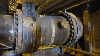
38 2. Pictures of applications Stage 2-3 Stage 1-2 Interstage offset spools between pumps (tailings) Stage 1-2 Stage 2-3 Operating pressure: 150 psi (10,3 bar) 170 psi (11,75 bar) Test pressure (2x WP): 300 psi (20,6 bar) 340 psi (23,5 bar) Bursting pressure: 609 psi (42 bar) 609 psi (42 bar) Design temperature: 90 C (194 F) 90 C (194 F) Compression: 1,2 (30 mm) 1,2 (30 mm) Elongation / Expansion: 1,6 (40 mm) 1,6 (40 mm) Offset: 5,31 (135 mm) 6,10 (155 mm) 38(47)
 Operating pressure: Test pressure: Bursting pressure: 145 psi (10 bar) 225 psi (15 bar) 435 psi")
39 Expansion Joint with 3" branch (tailings) Expansion joint ø26,5 x 40,5 (ø673 x 1075 mm.) Operating pressure: Test pressure: Bursting pressure: 145 psi (10 bar) 225 psi (15 bar) 435 psi (30 bar) 39(47)
 Operating pressure: Design pressure:")
 971 psi (67 bar) 2030 psi (140 bar) 40(47)")
40 High pressure hose with adapter flanges (tailings) ø26 x13 (ø660x4064 mm) Operating pressure: Design pressure: Test pressure : Bursting pressure: 348 psi (24 bar) 508 psi (35 bar) 971 psi (67 bar) 2030 psi (140 bar) 40(47)
 x 49 ) Operating pressure : Test")

41 T-Joint (hydro-transport) ø572 (3x): (23 (3x) x 49 ) Operating pressure : Test pressure: Bursting pressure : 7 bar / 100 psi 21 bar / 305 psi 70 bar / 1015 psi 41(47)

42 Preformed Elbows ø24 5D 90 (tailings) ø585 x R=3018 mm Operating pressure: Test pressure: Bursting pressure: 10 bar / 150 psi 18 bar / 260 psi 62 bar / 900 psi 42(47)
 ø724 x 11800 (28,5 x 38-8 ) Operating pressure: Test pressure: Bursting")
43 Straight hose 30" x 38.7' (coarse tailings) ø724 x (28,5 x 38-8 ) Operating pressure: Test pressure: Bursting pressure: 33 bar / 480 psi 33 bar / 480 psi 100 bar / 1450 psi 43(47)

44 Preformed elbow 30" 5D 90 (coarse tailings) ø724 x R=3810 mm (28,5 x 38-8 ) Operating pressure: 36,2 bar / 525 psi Test pressure: Bursting pressure: 36,2 bar / 525 psi 110 bar / 1595 psi 44(47)
")
45 30 and 45 preformed elbows (hydro-transport) 45(47)

")

46 hoses 30" - 36" (RCW & MFT) 46(47)


47 Expansion Barrel 30" (Coarse tailings) In service since September Inspected after 5 months and 2500 hours, no wear. ø724 x 3300 (28,5 x10⁻⁹ ) Operating pressure: Bursting pressure: 38 bar / 550 psi 114 bar / 1650 psi 47(47)
Guide for Evaluating Your Hose Assembly Supplier
 Guide for Evaluating Your Hose Assembly Supplier Supplier Evaluation Checklist, and How to Clearly Define Application Requirements Safe, reliable hose assemblies require appropriate specification work
P-04 Stainless Steel Corrugated Hoses and Metal Bellows Expansion Joints
 Guideline No.P-04 (201510) P-04 Stainless Steel Corrugated Hoses and Metal Bellows Expansion Joints Issued date: 20 th October 2015 China Classification Society Foreword This Guideline is a part of CCS
ISO 4081 INTERNATIONAL STANDARD. Rubber hoses and tubing for cooling systems for internal-combustion engines Specification
 Provläsningsexemplar / Preview INTERNATIONAL STANDARD ISO 4081 Third edition 2010-06-01 Rubber hoses and tubing for cooling systems for internal-combustion engines Specification Tubes et tuyaux en caoutchouc
F-08 HIGH-PRESSURE HOSE USED IN CO2 SYSTEM
 Guideline No.: F-08(201510) F-08 HIGH-PRESSURE HOSE USED IN CO2 SYSTEM Issued date: October 20,2015 China Classification Society Foreword: This Guide is a part of CCS Rules, which contains technical requirements,
INTERLOCKED METAL HOSE
 INTERLOCKED METAL HOSE HOSE FUNDAMENTALS Penflex interlocked metal hoses are made for a variety of specialized industrial applications and are available in a wide range of metals, styles and sizes. Interlocked
STANDARD SPECIFICATION FOR SPLIT TEES (HOT TAP MATERIAL)
") STANDARD SPECIFICATION FOR SPLIT TEES (HOT TAP MATERIAL) TEE (HOT TAPPING MATERIAL) S-04-02-040 Page 1 of 7 1.0 SCOPE This specification covers the basic requirements for the design, manufacture and supply
STANDARD SPECIFICATION FOR SPLIT TEES (HOT TAP MATERIAL) TEE (HOT TAPPING MATERIAL) S-04-02-040 Page 1 of 7 1.0 SCOPE This specification covers the basic requirements for the design, manufacture and supply
Rubber Dock Hose care, Use & Maintenance
 Rubber Dock Hose care, Use & Maintenance Prepared by: Thomas J. Wise VP Corporate Development Contents Revised - July. 2014 1. Novaflex Rubber Dock Hose Testing & Inspection Program 1.1 Introduction -
Flexible Metal Hose Products
 Flexible Metal Hose Products Specialty Flexible Hose Solutions of Stainless Steel The AEROCOM Advantage Aerocom offers engineered solutions that address specific flexible piping challenges such as vibration,
Material Handling Hose
 Novaflex 5000 Slurry King Hose Pure Gum Liner Tough, versatile alternative to inflexible, cumbersome steel tubing. The easy handling and reusable quick-fastening flange system make installation a snap.
IAPMO GUIDE CRITERIA FOR BALL VALVES IAPMO IGC PURPOSE
 INTERNATIONAL ASSOCIATION OF PLUMBING AND MECHANICAL OFFICIALS IAPMO GUIDE CRITERIA FOR BALL VALVES IAPMO IGC 157-20067 1 PURPOSE 1.1 The purpose of this standard is to establish an acceptable standard
Flexible hoses - Non-metallic materials
 CLASS PROGRAMME Type approval DNVGL-CP-0183 Edition December 2015 The electronic pdf version of this document, available free of charge from http://www.dnvgl.com, is the officially binding version. FOREWORD
ISO 6804 INTERNATIONAL STANDARD. Rubber and plastics inlet hoses and hose assemblies for washing-machines and dishwashers Specification
 INTERNATIONAL STANDARD ISO 6804 Third edition 2009-09-15 Rubber and plastics inlet hoses and hose assemblies for washing-machines and dishwashers Specification Tuyaux et flexibles en caoutchouc et en plastique
Fluid Sealing Association
 Fluid Sealing Association STANDARD FSA-PSJ-701-06 PIPING SYSTEMS NON-METALLIC EXPANSION JOINT HYDROTESTING AND VACUUM TESTING 994 Old Eagle School Road, Suite 1019 Wayne, Pennsylvania 19087-1866 Phone:
DREDGING & MINING MEDIUM DUTY ABRASIVES HANDLING HOSE
 MEDIUM DUTY ABRASIVES HANDLING HOSE A16, A17, A18, A25, A32, A39 Hand-built hard wall suction hose. Animal feeds, grains, flours, powders, cement, sand, dry waste, rubble. 51mm (2 ) to 254mm (10 ) 12 metres.
SUPPLY OF ISOLATION AND APPLIANCE VALVES PTS - APPLIANCE BALL VALVE
 PTS - APPLIANCE BALL VALVE 2 30.06.17 Issued for Tender AS ADE GS 1 12.04.17 Issued for Tender AS AD GS 0 06.03.17 Issued for Client s Comments AS AD GS Rev. Date Subject of revision Author Checked Approved
Unit 1, Fullerton Road Rotherham S60 1DJ. Tele: Fax:
 Unit 1, Fullerton Road Rotherham S60 1DJ Tele: 0845 601 333 6 Fax: 0845 601 333 7 info@fabricatedproducts.co.uk www.fabricatedproducts.co.uk Data Sheet 6.0 Rubber Pump Flexes All rubber bellows are suitable
INSTALLATION, OPERATION AND MAINTENANCE GUIDE
 INSTALLATION, OPERATION AND Placement in Pipeline System When installing Process Development & Control s ElastoTITE Elastomer-Hinged Check Valves in a pipeline, a minimum of five pipe diameters should
Hydrostatic Pressure Testing
 General An experienced or qualified person will be put in charge of hydro and should meet with the supervisor in charge of the job prior to test. Customer expectations should be clarified prior to beginning
Inspection and Test Plan for Gas Circuit Breaker
 Inspection and Test Plan for Gas Circuit Breaker No. Inspection and Test Plan Reference Document Acceptance Criteria Verifying Document Activity By Remark Manuf. TPI Client 1 Pre Inspection Meeting Spec.
PIP PNE00012 Piping Examination and Leak Test Guide
 October 2017 Piping PIP PNE00012 Piping Examination and Leak Test Guide PURPOSE AND USE OF PROCESS INDUSTRY PRACTICES In an effort to minimize the cost of process industry facilities, this Practice has
ACCREDITATION OF ON-LINE LEAK SEAL ORGANIZATIONS
 ACCREDITATION OF ON-LINE LEAK SEAL ORGANIZATIONS TSSA GUIDE FOR SURVEY TEAMS The Technical Standards and Safety Authority Boilers and Pressure Vessels Safety Division 3300 Bloor Street West 14th Floor,
Guideline No.M-05(201510) M-05 AIR COMPRESSOR. Issued date: 20 October China Classification Society
 M-05 AIR COMPRESSOR. Issued date: 20 October China Classification Society") Guideline No.M-05(201510) M-05 AIR COMPRESSOR Issued date: 20 October 2015 China Classification Society Foreword This Guideline constitutes the CCS rules, and establishes the applicable technical requirements
Guideline No.M-05(201510) M-05 AIR COMPRESSOR Issued date: 20 October 2015 China Classification Society Foreword This Guideline constitutes the CCS rules, and establishes the applicable technical requirements
Flange Bolt Torquing. for Resistoflex Plastic-Lined Piping Products. Torquing. Retorquing. Hydrotesting. Annual retorquing
 Flange Bolt Torquing for Resistoflex Plastic-Lined Piping Products Torquing When assembling flange connections, always use a full complement of clean, new high strength A193-B7 bolting. If using stainless
Translation Principles of testing and certification for insulating hose assemblies on cable cutting devices
 Translation Principles of testing and certification for insulating hose assemblies on cable cutting devices Status as of 2014-01 Principles of testing Insulating hose assemblies on cable cutting devices
ISO/TC 131/SC Hydraulic fluid power Test methods for hoses and hose assemblies
 DRAFT INTERNATIONAL STANDARD ISO/DIS 6605 ISO/TC 131/SC 4 Secretariat: ANSI Voting begins on: Voting terminates on: 2016-02-03 2016-05-03 Hydraulic fluid power Test methods for hoses and hose assemblies
Materials : Dichromate zinc plated steel flanges
 Size : Ends : Min Temperature : Max Temperature : DN 25 to 300 Flanges PN10/16-35 C + 130 C Max Pressure : 16 Bars up to DN150, 10 bars over Specifications : Absorb vibrations and noise Linear and angular
SABERINDO PACIF SABERINDO PACIFIC CIFIC SABERINDO PA. A Tyco International Company
 CIF A Tyco International Company 1 Foam Concentrate CIF 3% AFFF -UL Listed -UL Canada Listed 6% AFFF 6 parts AFFF concentrate to 94 parts water -UL Listed- Foam Liquid -UL Canada Listed 3% FLUOROPROTEIN
A hose layline contains important information for specifying the replacement assembly: manufacturer, hose trade name, working pressure and hose ID.
 CONTENTS Introduction Pressure Pressure Drop Temperature Rating Bend Radius Conclusion Additional Information SIDEBAR: Understanding Hydraulic Hose Reinforcement INTRODUCTION Hydraulic hose has a finite
BIMBAR INFLATABLE PACKERS AND ACCESSORIES
 BIMBAR INFLATABLE PACKERS AND ACCESSORIES Geopro supplies a complete range of inflatable packers in nine different diameters from 28 up to 170mm. All our packers made of BIMBAR rubber technology are reinforced
Spilt body Flange ball valve. TC-205MFF-PN1640 User Manual English Version. Document No: TC-205MFF-PN1640.Ur-manual. Date: 2007/04/2617. Version: 1.
 Spilt body Flange ball valve TC-205MFF-PN1640 Series PED Category I,II TC-205MFF-PN1640 User Manual English Version Use for company in Europe who will place the product on the market, please amend which
ISO 3996 INTERNATIONAL STANDARD. Road vehicles - Brake hose assemblies for hydraulic braking Systems used with non-petroleum-base brake fluid
 Provläsningsexemplar / Preview INTERNATIONAL STANDARD ISO 3996 Third edition 1995-02-01 Road vehicles - Brake hose assemblies for hydraulic braking Systems used with non-petroleum-base brake fluid Vkhicules
A Rationale for Pressure Relief Device(s) Qualification Requirements (LH2)
 Qualification Requirements (LH2)") UN-GTR PART A INSERTION Stand 09.02.2011, 17:20 Uhr A.3.3 HYDROGEN STORAGE SYSTEM The hydrogen storage system consists of all components that form the primary pressure boundary of the stored hydrogen in
UN-GTR PART A INSERTION Stand 09.02.2011, 17:20 Uhr A.3.3 HYDROGEN STORAGE SYSTEM The hydrogen storage system consists of all components that form the primary pressure boundary of the stored hydrogen in
INSTALLATION & MAINTENANCE INSTRUCTIONS - ORIGINAL VERSION AVK KNIFE GATE VALVES
 1. INTRODUCTION The AVK knife gate valve is a unique, patented, bi-directional on-off valve that ensures a bubble-tight shut off. The valve is available with body of ductile iron and seat of nitrile, viton,
TRZ 03-K Volumeter. Proven Technology. Superior Performance. TRZ 03-K Volumeter is a Turbine Gas Flowmeter for Secondary Gas Metering.
 TRZ 0-K Volumeter TRZ 0-K Volumeter is a Turbine Gas Flowmeter for Secondary Gas Metering. TRZ 0-K Turbine Gas Flowmeter continues the tradition of Honeywell s field-proven turbine meter technology, delivering
New! ProFlow. Sliding Vane Meters DN (½ - 2 ) _ 142. Product Bulletin
 _ 142. Product Bulletin") New! ProFlow Sliding Vane Meters DN 15-5 (½ - 2 ) _ 142 Product Bulletin WWW.VAF.NL 1 Introduction VAF Instruments ProFlow positive displacement sliding vane type liquid flowmeters are used in continuous
New! ProFlow Sliding Vane Meters DN 15-5 (½ - 2 ) _ 142 Product Bulletin WWW.VAF.NL 1 Introduction VAF Instruments ProFlow positive displacement sliding vane type liquid flowmeters are used in continuous
SUPPLY OF ISOLATION AND APPLIANCE VALVES PTS - ISOLATION BALL VALVE
 PTS - ISOLATION BALL VALVE 2 30.06.17 Issued for Corrigendum#1 AS ADE GS 1 12.04.17 Issued for Tender AS AD GS 0 06.03.17 Issued for Client s Comments AS AD GS Rev. Date Subject of revision Author Checked
ASME and PED Requirements for Drum Level Instrumentation. Presented by: Amir Hedayatnia Clark-Reliance Corp.
 ASME and PED Requirements for Drum Level Instrumentation 2017 Presented by: Amir Hedayatnia Clark-Reliance Corp. Topics Gage Glasses and Remote Reading Instruments ASME Code Section I Requirements for
ASSE International Product (Seal) Listing Program
 Listing Program") ASSE International Product (Seal) Listing Program ASSE 1070-2015 / ASME A112.1070-2015 / CSA B125.70-15 Performance Requirements for Water Temperature Limiting Devices Manufacturer: Contact Person: E-mail:
ASSE International Product (Seal) Listing Program ASSE 1070-2015 / ASME A112.1070-2015 / CSA B125.70-15 Performance Requirements for Water Temperature Limiting Devices Manufacturer: Contact Person: E-mail:
RESISTANCE OF COMPACTED ASPHALT MIXTURE TO MOISTURE INDUCED DAMAGE (Kansas Test Method KT-56)
") 5.9.56 RESISTANCE OF COMPACTED ASPHALT MIXTURE TO MOISTURE INDUCED DAMAGE (Kansas Test Method ) 1. SCOPE This test covers preparation of specimens and measurement of the change of tensile strength resulting
5.9.56 RESISTANCE OF COMPACTED ASPHALT MIXTURE TO MOISTURE INDUCED DAMAGE (Kansas Test Method ) 1. SCOPE This test covers preparation of specimens and measurement of the change of tensile strength resulting
Standard Pneumatic Test Procedure Requirements for Piping Systems
 the pressure equipment safety authority Standard Pneumatic Test Procedure Requirements for Piping Systems AB-522 Edition 2, Rev. 1 Issued 2016-10-24 Table of Contents FOREWORD... 1 1.0 INTRODUCTION...
Material Handling Hose
 Novaflex 5000 Slurry King Pure Gum Liner Tough, versatile alternative to inflexible, cumbersome steel tubing. The easy handling and reusable quick-fastening flange system make installation a snap. Absorbs
Dredging hoses and applications. Trelleborg Velp
 Dredging hoses and applications Trelleborg Velp Introduction Trelleborg Velp is made up of a team of professionals specializing in rubber material handling hoses, so that development, production, advertising
Horizontal Bladder Tanks
 DATA SHEET Horizontal Bladder Tanks Features UL Listed and FM Approved for use with various ANSUL proportioners and foam concentrates 175 psi (12.1 bar) maximum allowable working pressure (design pressure)
General Performance Data Hose Ref Minimum Bend. Safety Pressure at 20 C (BAR) Working Pressure at. Flow Rate at 3 bar (lit/min) Working Pressure
 Working Pressure at. Flow Rate at 3 bar (lit/min) Working Pressure") The Classic range provides a safe and taint free conveyance of potable water supplies for Domestic and Commercial plumbing applications. The range is designed to achieve robust and flexible solutions with
The Classic range provides a safe and taint free conveyance of potable water supplies for Domestic and Commercial plumbing applications. The range is designed to achieve robust and flexible solutions with
HYDROSTATIC LEAK TEST PROCEDURE
 This information is proprietary and shall not be disclosed outside your organization, nor shall it be duplicated, used or disclosed for purposes other than as permitted under the agreement with Kinetics
Date of Issue: July 2016 Affected Publication: API Specification 16C, Choke and Kill Equipment, Second Edition, March 2015 ADDENDUM 1
 Date of Issue: July 2016 Affected Publication: API Specification 16C, Choke and Kill Equipment, Second Edition, March 2015 ADDENDUM 1 Page 16, Section 4.6, delete the entire section and renumber all subsequent
ASYBCO 90 O ELBOW LONG RADIUS O.D. I.D.
 90 O ELBOW LONG RADIUS Standard weight Extra strong Schedule 160 Double extra strong ASTM A-234 ASME / ANSI B16.9 Carbon and ferritic alloy steel Produced from X-rayed, stress-relieve welded pipe. Welds
Standard Test Methods for Rubber Hose 1
 Designation: D 380 94 (Reapproved 2000) Standard Test Methods for Rubber Hose 1 This standard is issued under the fixed designation D 380; the number immediately following the designation indicates the
BUTTERFLY VALVES. Toll Free (877) - ICFLUID -2-
 - ICFLUID -2-") BUTTERFLY VALVES 1. General HyrdoWer is a globally recognized manufacturer of power unit accessories. They have become specialists in the design of Butterfly Valves and Hydraulic Compensators. The shut
BUTTERFLY VALVES 1. General HyrdoWer is a globally recognized manufacturer of power unit accessories. They have become specialists in the design of Butterfly Valves and Hydraulic Compensators. The shut
GUKO FDA. einfach. gut. beraten.
 GUKO FDA Size : Ends : Min Temperature : Max Temperature : DN 25 to 300 Flanges PN10/16-25 C + 90 C Max Pressure : 16 Bars Specifications : Absorb vibrations and noise Linear and angular compansion Inner
Materials : Dichromate zinc plated steel flanges or AISI 316
 Size : Ends : Min Temperature : Max Temperature : DN 25 to 300 Flanges PN10/16-35 C + 90 C Max Pressure : 16 Bars (10 bars at 90 C) Specifications : Absorb vibrations and noise Linear and angular compansion
AWWA C504 COMPLIANT VALVES FROM 3 THRU 108
 AWWA C504 COMPLIANT VALVES FROM 3 THRU 108 PO Box 411 Berwick PA 18603 800-247-VALV www.crispinvalve.com 500 SERIES: Sizes 3-20 Available The K-Flo 500 Series is a heavy-duty resilient seated butterfly
1 Exam Prep. Tabs and Highlights
 1 Exam Prep NFPA 14: Standard for the Installation of Standpipe and Hose Systems Tabs and s These 1 Exam Prep tabs are based on the NFPA 14: Standard for the Installation of Standpipe and Hose Systems,
Instruction Manual Pressure Relief Valve and Rupture Disc Chlorine or Sulfur Dioxide, Series 869
 Instruction Manual Pressure Relief Valve and Rupture Disc Chlorine or Sulfur Dioxide, Series 869-1 - 115.6020.15 These instructions describe the installation, operation and maintenance of the subject equipment.
Hose Manufacturing Data
 Hydraulic & Offshore Supplies Hose Manufacturing Data YOUR GATEWAY TO GLOBAL SUPPLY HOSE ASSEMBLIES PRESSURE TESTING WALFORM EQUIPMENT PACKAGES FLANGES PIPE & TUBE HOSE MANUFACTURING DATA STORAGE Detailed
Vertical and Horizontal Bladder Tanks
 DATA SHEET Vertical and Horizontal Tanks Application The ANSUL bladder tank is one component in a balanced pressure proportioning system. Its operation requires no external power other than a pressurized
USA (Bartlett, IL) Division
 Division") USA (Bartlett, IL) Division USA (Bartlett, IL) Division 100+ years Manufacturing Experience Six Sigma Black Belt (2) 350,000 Sq. Ft. Manufacturing & Office Total Program Development & Management Product
USA (Bartlett, IL) Division USA (Bartlett, IL) Division 100+ years Manufacturing Experience Six Sigma Black Belt (2) 350,000 Sq. Ft. Manufacturing & Office Total Program Development & Management Product
HDPE. Dredging Pipeline
 HDPE Dredging Pipeline R Ace Flowtech Co., Ltd Office address: No.2, 2-1601, Rongyuan Road, Huayuan Industrial Park, Tianjin Binhai Hi- Tech Area, Tianjin City, China, 300384 Factory address: No.51 Lutai
17J Third Edition, January 2008 Specification for Unbonded Flexible Pipe
 API Specification 17J Third Edition, January 2008 National Adoption of ISO 13628:2006(Identical) Petroleum and natural gas industries Design and operation of subsea production systems Part 2: Unbonded
DR.ING. CARLO AVANZINI PROFESSIONAL ENGINEER GRIP TEST REPORT NOVA SIRIA, ROLETTO, Premise
 GRIP TEST REPORT NOVA SIRIA, ROLETTO, 07.10.2013 1. Premise The present report covers the witnessing of the test conducted in the Nova Siria Factory in Roletto (Torino, Italy) to verify the behavior of
THE PROCESS OF JOINT INTEGRITY
 BOLTED JOINTS A.333 THE PROCESS OF JOINT INTEGRITY To assist in managing a process, ask yourself the following questions: why, what, who, and how? Why do we need a Flange Joint Integrity program? This
Vertical Bladder Tanks
 DATA SHEET Vertical Bladder Tanks Features UL Listed and FM Approved for use with various ANSUL proportioners and foam concentrates 175 psi (12.1 bar) maximum allowable working pressure (design pressure)
DETAIL SPECIFICATION HOSE ASSEMBLIES, ELASTOMERIC HYDRAULIC FLUID, FUEL, AND OIL RESISTANT, GENERAL SPECIFICATION FOR
 INCH-POUND MIL DTL 8795E 22 September 2000 SUPERSEDING MIL H 8795D 14 October 1985 DETAIL SPECIFICATION HOSE ASSEMBLIES, ELASTOMERIC HYDRAULIC FLUID, FUEL, AND OIL RESISTANT, GENERAL SPECIFICATION FOR
Model 130M Pneumatic Controller
 Instruction MI 017-450 May 1978 Model 130M Pneumatic Controller Installation and Operation Manual Control Unit Controller Model 130M Controller is a pneumatic, shelf-mounted instrument with a separate
Model MTB-ASME Vertical Bladder Tanks
 DATA SHEET Model MTB-ASME Vertical Bladder Tanks Features n UL Listed for use with various proportioners and foam concentrates n 175 psi (12.1 bar) maximum allowable working pressure (design pressure)
Model MTB-ASME Horizontal Bladder Tanks
 DATA SHEET Model MTB-ASME Horizontal Bladder Tanks Features n UL Listed and FM Approved for use with various proportioners and foam concentrates n 175 psi (12.1 bar) maximum allowable working pressure
PLEASE NOTE: Pressures for 200mm (8ins) and 250mm (10ins) are based on the use of METALFLEX Braided Braid
 and 250mm (10ins) are based on the use of METALFLEX Braided Braid") METCONAB B-FLEX Stainless Steel Annular Convoluted Hose. A close pitch hose with a high degree of flexibility suitable for most applications and normally supplied. BRAID Single or double layers of Stainless
METCONAB B-FLEX Stainless Steel Annular Convoluted Hose. A close pitch hose with a high degree of flexibility suitable for most applications and normally supplied. BRAID Single or double layers of Stainless
v. Size shall be specified on drawings.
 SPECIFICATION FOR VACUUM INSULATED PIPING Part 1 General 1. Submittals a. After award of contract and before executing any manufacturing, shop drawings and specifications shall be submitted to the customer
Technical Standard. API6D Ball & Plug Valve. Inspection & Test Procedure
 Technical Standard API6D Ball & Plug Valve Inspection & Test Procedure 1 Scope This standard provides specific inspection items to be performed on all ball & plug valves. The valves shall be provided with
Model MTB-ASME Vertical Bladder Tanks
 DATA SHEET Model MTB-ASME Vertical Bladder Tanks Features n UL Listed for use with various proportioners and foam concentrates n 175 psi (12.1 bar) maximum allowable working pressure (design pressure)
Hoses and Lances 20,000 PSI
 Jetstream provides a full arrangement of hoses and flex lances for ultra high pressure waterblasting. The hoses and lances are designed to be durable and reliable for any 20,000 psi application. A large
Tex-616-J, Construction Fabrics
 Contents: Section 1 Overview... Section s...3 Section 3 Archived Versions...10 Texas Department of Transportation 1 06/00 1/07 Section 1 Overview Effective dates: June 000 December 007. Section 1 Overview
CLASS D - SENSITIVE LEAK TEST GAS AND BUBBLE METHOD. 1.1 To provide definitive requirements for PNEUMATIC pressure testing of piping systems.
 Page 1 of 7 CLASS D - SENSITIVE LEAK TEST GAS AND BUBBLE METHOD 1. SCOPE 1.1 To provide definitive requirements for PNEUMATIC pressure testing of piping systems. 1.2 The piping system as used herein is
Telefon (+45) Telefax (+45)
 Telefax (+45)") Uni-Valve A /S VENTILER & INSTRUMENTER Telefon (+45) 43 43 82 00 Telefax (+45) 43 43 74 75 mail@uni-valve.com www.uni-valve.com UNI-S83 / S84 3/4-way ball valve Installation and Operating manual 3/4-WAY
Uni-Valve A /S VENTILER & INSTRUMENTER Telefon (+45) 43 43 82 00 Telefax (+45) 43 43 74 75 mail@uni-valve.com www.uni-valve.com UNI-S83 / S84 3/4-way ball valve Installation and Operating manual 3/4-WAY
1 Scope... 2 Functions of cementing float equipment... 3 Definitions... 4 Calibration... 5 Test Categories... 6 General...
 American Petroleum Institute Contents Page 1 Scope... 2 Functions of cementing float equipment... 3 Definitions... 4 Calibration... 5 Test Categories... 6 General... 7 Apparatus and Materials... 8 High-temperature/high-pressure
Wafer Check Valve. Contents. User s Manual. (1) Be sure to read the following description of our product warranty 1
 Be sure to read the following description of our product warranty 1") Serial No. H-V066-E-3 Wafer Check Valve User s Manual Contents (1) Be sure to read the following description of our product warranty 1 (2) General operating instructions 2 (3) General instructions for
Serial No. H-V066-E-3 Wafer Check Valve User s Manual Contents (1) Be sure to read the following description of our product warranty 1 (2) General operating instructions 2 (3) General instructions for
TECHNICAL DATA. Q = C v P S
 Page 1 of 13 1. DESCRIPTION The Viking 6 Model G-6000 Dry Valve Riser Assembly consists of a small profile, light weight, pilot operated valve that is used to separate the water supply from the dry sprinkler
Inspection and Approval of Asphalt Mix Design Laboratories
 Supplemental Technical Specification for Inspection and Approval of Asphalt Mix Design Laboratories SCDOT Designation: SC-M-405 (06/07) 1. SCOPE 1.1 This method covers the process for inspection and approval
CERTIFICATION OF COMPLIANCE OF THE USER S DESIGN SPECIFICATION
 CERTIFICATION OF COMPLIANCE OF THE USER S DESIGN SPECIFICATION I, the undersigned, being experienced and competent in the applicable field of design related to pressure vessel requirements relative to
This document is a preview generated by EVS
 INTERNATIONAL STANDARD ISO 6605 Third edition 2017-06 Hydraulic fluid power Test methods for hoses and hose assemblies Transmissions hydrauliques Méthodes d essai pour les tuyaux et flexibles Reference
WHEATLEY WHEATLEY SERIES 500 SWING CHECK VALVE. Installation, Operation and Maintenance Manual
 WHEATLEY SERIES 500 SWING CHECK VALVE STANDARD INTEGRAL SEAT & OPTIONAL REMOVABLE SEAT 2" FP - 6" FP 150# - 1500# 8" FP - 12" FP 150# - 900# API 6D and B16.34 2" FP - 4" FP 5000# DRILLING PRODUCTION VALVE
WHEATLEY Series 500 Swing Check Valve
 Document Number: TC003001-13 Revision: 02 WHEATLEY Series 500 Swing Check Valve Installation, Operation, and Maintenance Manual TABLE OF CONTENTS BILL OF MATERIALS...3 SCOPE...5 INSTALLATION AND OPERATION
SCOPE OF ACCREDITATION TO ISO/IEC 17025:2005
 SCOPE OF ACCREDITATION TO ISO/IEC 17025:2005 CORPORATE CONSULTING, SERVICE, & INSTRUMENTS, INC. University Park, 221 Beaver Street Akron, OH 44304 Michael Kent Warner Phone: 330 376 3600 CALIBRATION Valid
M-14 Stern Shaft Sealing Apparatus
 Guideline No.M-14 (201705) M-14 Stern Shaft Sealing Apparatus Issued date: May 9,2017 China Classification Society Foreword This Guideline is a part of CCS Rules, which contains technical requirements,
Quick reference. Quick reference
 Quick reference Quick reference Measurement methodology for frequently occurring hose fittings Hose size ight series Heavy series Fine thread Banjo French (pipe in inches) French ( pipe light) French (
Corrugated Hose Loop Calculations
 Corrugated Hose Loop Calculations The loop installation is one of the most common application for metal hoses. It allows the flexible hose assembly to work properly. Care must always be exercised to ensure
DNVGL-CP-0187 Edition March 2016
 CLASS PROGRAMME Type approval DNVGL-CP-0187 Edition March 2016 The electronic pdf version of this document, available free of charge from http://www.dnvgl.com, is the officially binding version. FOREWORD
CONTENTS Article NC-1000 Introduction Figures Article NC-2000 Material
 CONTENTS Foreword... xv Statements of Policy... xvii Personnel... xix Organization of Section III... xxxi Summary of Changes... xxxiii List of Changes in BC Order... xxxiv Article NC-1000 Introduction...
Other Si min/max. Cr min/max. 0.4/ / / / Bal.
 178.46 Specification 3AL seamless aluminum cylinders. (a) Size and service pressure. A DOT 3AL cylinder is a seamless aluminum cylinder with a imum water capacity of 1000 pounds and minimum service pressure
Safety relief valves Type SFV 20-25
 Data sheet Safety relief valves Type SFV 20-25 SFV 20-25 are standard, back pressure dependent safety relief valves in angle-way execution, specially designed for protection of vessels and other components
OVERVIEW LOADING & DISCHARGE HOSES FOR OFFSHORE MOORINGS
 Hose range in accordance with OCIMF Guide to Purchasing, Manufacturing and Testing of Loading and Discharge Hoses for Offshore Moorings, Fourth Edition 1991 OVERVIEW LOADING & DISCHARGE HOSES FOR OFFSHORE
ISO INTERNATIONAL STANDARD. Hydraulic fluid power Hose assemblies Part 1: Dimensions and requirements
 INTERNATIONAL STANDARD ISO 17165-1 First edition 2007-10-15 Hydraulic fluid power Hose assemblies Part 1: Dimensions and requirements Transmissions hydrauliques Flexibles de raccordement Partie 1: Dimensions
Product Technical Data and Certification PASSPORT OF GOODS. Q-SEAL SYSTEM (multiple seal) Ruma Products BV. Hoogeveen Holland.
 Ruma Products BV. Hoogeveen Holland.") Product Technical Data and Certification PASSPORT OF GOODS Q-SEAL SYSTEM (multiple seal) Ruma Products BV. Hoogeveen Holland. PASSPORT OF GOODS Content Background Information... 2 Composition... 2 Function
Product Technical Data and Certification PASSPORT OF GOODS Q-SEAL SYSTEM (multiple seal) Ruma Products BV. Hoogeveen Holland. PASSPORT OF GOODS Content Background Information... 2 Composition... 2 Function
Perform Pressure & Leak Test, Tubing & Piping. Module 12306
 Perform Pressure & Leak Test, Tubing & Piping Module 12306 Instrumentation Trainee Task Module 12306 PERFORM PRESSURE AND LEAK TEST, TUBING AND PIPING Objectives Upon completion of this module, the trainee
TIGHTNESS. Glass sealing Thanks to our glass-sealing technology, ODU products can meet the most demanding tightness requirements.
 TIGHTNESS Glass sealing Thanks to our glass-sealing technology, ODU products can meet the most demanding tightness requirements. ODU has the necessary expertise for developing and manufacturing connectors
ASSESSMENT AND ANALYSIS OF PIPELINE BUCKLES
 ASSESSMENT AND ANALYSIS OF PIPELINE BUCKLES GE Oil & Gas PII Pipeline Solutions Inessa Yablonskikh Principal Consultant Aberdeen, November, 14 th 2007 Assessment And Analysis Of Pipeline Buckles Introduction
OPENINGS AND REINFORCEMENTS 26
 ASME BPVC.VIII.1-2015 UG-35.2 UG-36 (4) It is recognized that it is impractical to write requirements to cover the multiplicity of devices used for quick access, or to prevent negligent operation or the
TEST BENCH SAFETY VALVES ¼ - 5 DN10 DN125
 TEST BENCH SAFETY VALVES ¼ - 5 DN10 DN125 Model: VC-40-VYC Table of contents 1. - Installing the test bench 1.1.1- Connecting the compressed air / nitrogen source 1.1.2- Maximum test pressure according
Shri Krishna Test House, B-70/1, Gali No. 8, New Modern Shahdara, Mansarover Park, Delhi. Discipline Mechanical Testing Issue Date
 Last Amended on - Page 1 of 14 I. PERFORMANCE TEST 1. Domestic gas Stove for use with L.P.G. General Cl. 4, IS:5116 & Cl.4.1.1 of IS:4246 Material Cl. 5 of IS:5116 Design for Maintenance Cl. 6.2, 6.3,
RS Pro 300mm Long EPDM 15bar Braided Stainless Steel Hose RS Stock No
 Datasheet RS Pro 300mm Long EPDM 15bar Braided Stainless Steel Hose RS Stock No.711-8476 Description: The Elite range provides robust and flexible solution for the safe conveyance and distribution of water