Atlas Copco Compressed Air Piping System
|
|
|
- Alexandra Cooper
- 5 years ago
- Views:
Transcription


1 Atlas Copco Compressed Air Piping System Catalog Ordering and Installation Guide


2 QUALITY AIR WHERE YOU NEED IT SYSTEM SAVINGS HIGH COMPATIBILITY QUICK TO INSTALL 1
 and variety of specialized tools, brackets and")


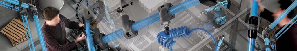
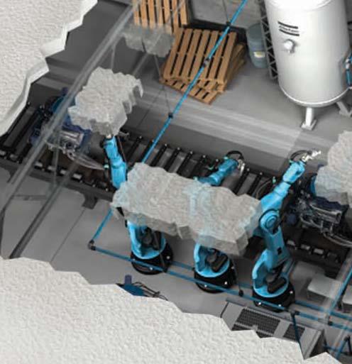
3 A COMPLETE SOLUTION The AIRnet compressed air piping system is a complete solution from source to production thanks to its high quality aluminium pipes, its range of aluminium and polymer fittings from Ø20-80 mm (¾ - 3 ) and variety of specialized tools, brackets and bushing. HIGH MATERIAL RESISTANCE The AIRnet piping system is resistant to corrosion, mechanical shocks, thermal variations and outdoor weather conditions. THE FLEXIBLE FIT AIRnet s thread assembly, system cleanness and easy disassembly mean full reusability, fast extension possibilities, and full control over the network. MINIMUM LEAKAGE O-ring ensures an airtight fit. Resistant to vibration. No risk of corrosion. Easy system maintenance. No energy waste. AIRnet PLANNER VIRTUAL INSTALLATION AIRnet Planner creates a 3D installation diagram using real-size equipment and real-life environments. It also calculates the pressure drop and estimates the time needed for assembly. Other handy features include a bill of material and a detailed quotation file. Keep your eye out for this icon and learn some interesting facts! 2


4 GENERAL INFORMATION AIRnet 10 year guarantee In line with the high quality performance of our AIRnet product range, we offer our customer a 10 year guarantee on AIRnet fittings and aluminium pipes against any damages resulting from material defect. WARRANTY COVERAGE TERMS Use only genuine parts. Perform installation according to our instructions and guidelines. Never use the components below or in excess of its limit ratings. Protect your installation against shocks or vibrations, corrosive environments. Damaged parts and/or site conditions must be submitted for inspection, prior to the settlement of any claim. AIRnet warranty is restricted to component replacement only. Claims should be addressed to any Atlas Copco Customer Center or Authorized Atlas Copco distribution network according to the standard procedure. This 10 year guarantee is limited to providing you with a new AIRnet fitting or pipe and is subject to our determination that the fitting or pipe failed exclusively due to a defect in the material at the time of manufacture. 3


5 TABLE OF CONTENTS TABLE OF CONTENTS A. General Information... P 1-8 B. Product Catalog... P 9-32 To inform you on all items needed to install a complete compressed air piping system, the AIRnet product catalog is divided into 6 chapters. 1. Piping... P Fittings...P Accessories...P Installation Material... P Gripple... P Tools...P 34 C. Installation Guide...P

 absolute pressure. Operating temperature limits: -20 C (-4 F) / +70 C (158 F). Lowest allowable pressure dewpoint: -70 C (-94 F).")

6 GENERAL INFORMATION General specifications COMPLIANCY EN / Directive 97/23/EC and ASME B31.1 Complies with Common Pressure related approvals PED CE ASME MOL UDT SQL CRN DIR MOM-ASME Ø mm Ø63-80 mm Ø mm 3/ /2-2 21/2-3 3/ / /2-3 PERFORMANCE CRITERIA Compatible with compressed air, vacuum and inert gasses such as Nitrogen. Maximum working pressure PN13 for temperatures between -20 C (-4 F) and +70 C (158 F). Vacuum level 0.13 bar (1.88 psi) absolute pressure. Operating temperature limits: -20 C (-4 F) / +70 C (158 F). Lowest allowable pressure dewpoint: -70 C (-94 F). Resistant to the effect of compressor oils (mineral oil / PAO based / Esther based oils). The AIRnet range is fire-resistant (according to UL94 HB). AIRnet pipes are resistant to direct UV radiation and fittings are resistant to indirect UV radiation. Corrosion-free. Leakage-free. Silicone-free. Oil-free applications. Material PA6 with 30% fiberglass injection. Grip ring: stainless steel. Seal NBR 70SH rubber. Body color RAL Nut color RAL AIRnet logotype embossed. Part number. Nominal DN diameter. Date of manufacture (year / month) in casting data clock. Aluminium alloy EN-AB47100-EX Grip ring: stainless steel. Seal NBR 70SH rubber. Body color RAL Nut color RAL AIRnet logotype embossed. Part number. Nominal DN diameter. Date of manufacture (year / month) in casting data clock. Extruded aluminium ANSI B241 UNS alloy A96063 T5. Color RAL 5012 for air. Color RAL 6018 for inert gasses, e.g. Nitrogen. AIRnet logotype marking. Part number. Maximum design pressure indication. Nominal outside and inside diameter marked, e.g. Ø50 x 46 mm (2 x 1¾ ). Date of manufacture (year / week). TESTING PERFORMANCES We have applied the most severe testing conditions to our product to simulate the highest industrial standards. High pressure resistance during one hour. Burst pressure to extreme high pressure. Leakage-free test based on vibration cycle at different frequencies. Leakage-free test based on pressure pulsation test. 5
 2: Outlet AIRnet fitting diameter Ø25 mm (1 ) 21: Reducing socket 03: Lot size: pack of 3 pieces (The lot size indicates the minimum quantity")
 9 63 Air pipe 3m (10 ft) 9 61 N2 pipe 6m (20 ft) 10 01 S-bend 10 02 Equal socket")

7 GENERAL INFORMATION PRODUCT IDENTIFICATION 2810 A B C D E A: AIRnet range family index B: Inlet pipe diameter (OD) C: Thread OD or reduced AIRnet fitting diameter D: Fitting code E: Lot size Example: : AIRnet 4: Pipe diameter Ø40 mm (1½ ) 2: Outlet AIRnet fitting diameter Ø25 mm (1 ) 21: Reducing socket 03: Lot size: pack of 3 pieces (The lot size indicates the minimum quantity available for ordering.) Ø CODE Ø (inch/mm) / ½ 1 20 / ¾ 2 25 / / 1½ 5 50 / / 2½ 7 80 / 3 FITTING CODE FITTING PAGE NUMBER 00 Air pipe 6m (20 ft) 9 63 Air pipe 3m (10 ft) 9 61 N2 pipe 6m (20 ft) S-bend Equal socket elbow elbow Equal tee End cap Reducing tee / 09 Threaded reducing tee Quick drop / 12 Threaded quick drop / 14 Adaptor union / 16 Nipple socket male polymer / 18 Nipple socket male alu / 20 Nipple socket female alu Reducing socket / 27 Pipe clip & spacer 27 / / 24 Wall mounted bracket / 26 Threaded wall mounted nipple Valve / 53 Threaded valve / 50 Brackets 27 / / 29 / Tools Inner parts / 66 O-ring / 00 / 01 Flanges 21 All fittings are available in NPT and BSP threaded standards. 6


8 GENERAL INFORMATION AIRnet fitting design STRONG-GRIP INTERNAL DESIGN New design increasing grip, strength and safety (with stainless steel clinch ring) SPECIFIC NUT DESIGN Notches enable you to tightly secure the AIRnet spanner, without damaging the nut itself. SPECIFIC BODY DESIGN Very large inner body diameter eliminates the flow resistance and pressure drop. Flow guide reduces the pressure drop. PARTS IDENTITY Part number and diameter are embossed. AIRnet uses a single assembly method for all diameters, ensuring the shortest possible assembly time, from 1.5 minutes for the smallest to 4 minutes for the largest diameters. UNIQUE ASSEMBLY SYSTEM STEP STEP STEP Push the pipe into the fitting. Tighten the fitting by hand. Secure the connection with a spanner (only necessary for >Ø40 mm (>1½ ) fittings). 7
 pipes with P = 7 bar, the pressure drop (ΔP) equals 0.2 bar.")
 Aluminium and polymer fittings are corrosion-free. Corrosion protection depends on galvanization quality. No risk of corrosion when cutting the aluminium.")


9 GENERAL INFORMATION AIRnet vs. traditional galvanized pipes AIRnet PIPES GALVANIZED PIPES Smooth surface. Rough surface. Low friction factor. Friction factor is almost double of an aluminium pipe. Low initial pressure drop. (E.g. In a system with an air demand of 110 l/s, designed as a 400 m long ring of Ø50 mm (2 ) pipes with P = 7 bar, the pressure drop (ΔP) equals 0.2 bar.) High initial pressure drop. (E.g. In a system with an air demand of 110 l/s, designed as a 400 m long ring of Ø50 mm (2 ) pipes with P = 7 bar, the pressure drop (ΔP) equals 0.37 bar.) Aluminium and polymer fittings are corrosion-free. Corrosion protection depends on galvanization quality. No risk of corrosion when cutting the aluminium. Very low risk of leakage, which is not related to corrosion. When cutting the pipe, the galvanization is removed. The connection poses a high risk of corrosion at low level points where water can stagnate, resulting in a high risk of leakage. Lightweight pipes: a standard Ø50 mm (2 ) diameter pipe weighs less than 5 kg (11 lbs). Heavy pipes: a standard Ø50 mm (2 ) pipe weighs more than 25 kg (55 lbs). Short manual cutting time. Very long manual cutting time, electrical cutter may generate some metallic dust. Fast deburring of the pipe. Pipes can be simply pushed into the fitting. Threading the pipe requires a certain level of experience to avoid future leakage. The fittings can be tightened by hand and secured with a spanner. The galvanized fittings need to be tightened using a spanner. The risk of leakage depends on the quality of the thread. Modifying the network is easy: the fittings and pipes can be simply disassembled and re-used. Modifying the network is often difficult: after disassembly, the pipes have to be cut, changed, threaded and re-assembled. Standard painted blue (compressed air) or green (inert gases) for easy network identification. Pipes need to be painted in the appropriate color, adding to the total cost. 8

 Temperature limits: -20 C (-4 F) to +50 C (122 F) ambient temperature -20 C (-4 F) to +70 C (158 F) operating temperature 2810 1000 00 - DN 20 - PN 13 BAR To ensure a leakage-free and safe")

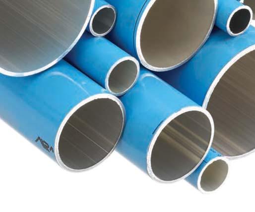
10 PRODUCT CATALOG PIPING PIPING ALUMINIUM PIPES Calibrated pipe / Color RAL 5012 for air pipes / Color RAL 6018 for Nitrogen pipes Qualicoat label / Fire resistant Operating limits: Maximum pressure: 13 bar (188 psi) Vacuum level = 0.13 bar (1.88 psi) Temperature limits: -20 C (-4 F) to +50 C (122 F) ambient temperature -20 C (-4 F) to +70 C (158 F) operating temperature DN 20 - PN 13 BAR To ensure a leakage-free and safe installation, only Atlas Copco s aluminium pipes have been calibrated, tested and approved for the assembly of AIRnet fittings. In most industrial standards, compressed air networks can be identified by their blue color. To optimize your installation costs, their standard length is 6 m (20 ft), which also is the standard industrial length. Aluminium pipe for air (6 m / 20 ft) OUTSIDE Ø INSIDE Ø LENGTH (m / ft) WEIGHT (kg / lbs) / ¾ 17.4 / / / / / / / / 1½ 36.4 / / / / / / / / 2½ 59.0 / / / / / / / m (10 ft) pipes are especially suitable for a short network extension or for an installation requiring a short length of a certain diameter. The 3 meter packs are available in different quantities. Aluminium pipe for air (3 m / 10 ft) OUTSIDE Ø INSIDE Ø LENGTH (m / ft) WEIGHT (kg / lbs) / ¾ 17.4 / / / / / / / / 1½ 36.4 / / / / / / / / 2½ 59.0 / / / / / / /


 long, rigid, pre-curved section of aluminium pipe, often used to fix drop legs closer to the wall when the main ring is")
11 PIPING PRODUCT CATALOG In most industrial standards, networks for inert gases, such as nitrogen, can be identified by their green color. The green AIRnet pipes can be used to assemble a network after GN compressors. Aluminium pipe for inert gases (6 m / 20 ft) OUTSIDE Ø INSIDE Ø LENGTH (m / ft) WEIGHT (kg / lbs) / ¾ 17.4 / / / / / / / DOUBLE S-BEND The double S-bend is a 50 cm (19.7 ) long, rigid, pre-curved section of aluminium pipe, often used to fix drop legs closer to the wall when the main ring is installed further away from the wall. Double S-bend LENGTH drop leg Ø 20 mm (¾ ) drop leg Ø 25 mm (1 ) (cm / inch) /


12 Design of the main ring and distribution lines The main ring is often the main skeleton of a network. This loop is located close to the main point of use, with drop legs connecting the main ring to your point of use, ensuring a minimal pressure drop. Using a main ring, the pressure drop is twice as low as when using a straight distribution line of the same length. In general, the main ring s diameter is based on the capacity of all compressors connected to the network, and should take possible future extensions into account. A distribution line is usually preferred to connect the main ring to a single point of use which is isolated in a remote location. The diameter of the distribution line should be based on the air demand at this specific point of use. Cross ring lines are distribution lines which connect the opposite sections of the main ring to guarantee a minimal pressure drop in other locations than the main point of use. 11


13 FITTINGS PRODUCT CATALOG FITTINGS EQUAL DIAMETERS Equal socket PART NUMBER Ø DIMENSIONS L W H / ¾ 102 / 4 36 / / / / / / / 1½ 199 / / / / / / / / 2½ 186 / / / / / / / elbow PART NUMBER Ø DIMENSIONS L W H / ¾ 82 / / / / / / / / 1½ 160 / / / / / / / / 2½ 168 / / / / / / / elbow Ø DIMENSIONS L W H / ¾ 106 / / / / / / / / 1½ 205 / / / / / / / Equal tee PART NUMBER Ø DIMENSIONS L W H / ¾ 127 / 5 82 / / / / / / / 1½ 249 / / / / / / / / 2½ 247 / / / / / / /


14 PRODUCT CATALOG FITTINGS REDUCING DIAMETERS Reducing socket Ø REDUCED Ø DIMENSIONS L W H / 1 20 / ¾ 115 / / / / 1½ 25 / / / / / 2 40 / 1½ 215 / / / Reducing tee Ø REDUCED Ø DIMENSIONS L W H / 1 20 / ¾ 155 / / / / 1½ 25 / / / / / 2 40 / 1½ 286 / / 7 89 / BALL VALVES AIRnet is compatible with standard industrial ball valves, using nipple sockets to connect the valves to the system. Please refer to the section Connection equipment on page 18 for more information on the nipple socket range. Ball valve (BSP thread) Ø DIMENSIONS L W H / ½ 127 / / / / ¾ 129 / / / / / / / / 1¼ 200 / / / / 1½ 204 / / / / / / / / / / / AIRnet valve Ø DIMENSIONS L W H / ¾ 140 / / / / / / / / 1½ 260 / / / / / / / / 2½ 220 / / / / / / /


15 FITTINGS PRODUCT CATALOG VALVES ARE USED FOR VARIOUS PURPOSES: To isolate a main ring, a distribution line or a drop leg. This facilitates possible future modifications of the system. To bypass air treatment equipment in order to perform service without stopping the air production. 14


. Quick drops are usually standardized to a single diameter all over the plant.")
 and Ø25 mm (1 ), matching standard drop leg sizes.")
16 PRODUCT CATALOG FITTINGS QUICK DROP Quick drops are specifically designed to connect a distribution line or a main ring to a drop leg from the middle of the pipe. This unique fitting design makes it possible to create a new drop leg extension in minimum time. As the connection is made from the side section, the risk of condensate pollutant is eliminated. 1 DRILLING HOLE Positioned at an exact 180 angle from the connecting hole, the drilling hole facilitates the preparation of the pipe. 2 CLAMP FIXTURE Loosen and tighten to adjust your quick drop around the pipe MARKINGS Indicate the optimum position of the pipe when drilling in order to match the final position. O-RING Ensures a leakage-free assembly. CONNECTED Ø Ranging from Ø25 mm (1 ) to Ø80 mm (3 ). 1 6 OUTLET Ø Available in two diameters: Ø20 mm (¾ ) and Ø25 mm (1 ) BRASS OUTLET Ø Robust; resistant to several assemblies (for threaded quick drops only). Quick drops are usually standardized to a single diameter all over the plant. The selected diameter should be based on the air demand at the point of use with the highest consumption. The quick drop range is available in two outlet diameters, Ø20 mm (¾ ) and Ø25 mm (1 ), matching standard drop leg sizes. A quick drop can be assembled in less than 5 minutes and does not require any specific tools. Quick drop MAIN Ø DIMENSIONS drop leg Ø 20 mm (¾ ) drop leg Ø 25 mm (1 ) L W H / / / / / 1½ 125 / / / / / / / / 2½ 148 / / / / / / /

 or Ø20 mm (¾ ) male inlets and have multiple purposes: Used as drop")


 2810 12 drop leg thread outlet Ø12.")

17 FITTINGS PRODUCT CATALOG THREADED QUICK DROP Threaded quick drops are designed to divert a distribution line or a main ring from the middle of the pipe. They can be connected to Ø12.5 mm (½ ) or Ø20 mm (¾ ) male inlets and have multiple purposes: Used as drop legs In combination with a rubber hose, the threaded quick drop outlets can be used to create drop legs. Connect point of use equipment A threaded quick drop almost instantly provides an additional point of use from the existing pipe, and can be used to hook up a spray air gun or air gun. Connect instrumentation devices Conveniently add pressure sensors or a pressure gauge to the network. Threaded quick drop (NPT thread) drop leg thread outlet Ø12.5 mm (½ ) drop leg thread outlet Ø20 mm (¾ ) MAIN Ø DIMENSIONS L W H / 1 90 / / / / 1½ 102 / 4 94 / / / / / / / 2½ 128 / / / / / / /


18 PRODUCT CATALOG FITTINGS THREADED REDUCING TEE Also a threaded reducing tee can be used to divert a distribution line or a main ring from the middle of the pipe in order to bypass an obstacle or avoid a difficult geometry. A threaded reducing tee is often used to connect a rubber hose to the system. Threaded reducing tee (NPT thread) Ø REDUCED THREAD OUTLET Ø DIMENSIONS L W H / ¾ 12.5 / ½ 127 / 5 85 / / / / ½ 155 / / / / 2½ 50 / / / / / 3 63 / 2½ 314 / / / / 3 80 / / / / NIPPLE SOCKET Nipple sockets are used to connect any sort of equipment to or from the inlet or outlet thread. Nipple sockets are key fittings which guarantee compatibility with any existing network or piece of equipment. A large range of nipple sockets is available to ease the connection to any existing thread. For each diameter, the thread outlet is available in 2 sizes: to connect to the same diameter, to connect to a smaller diameter (one size smaller). This limits the use of additional galvanized bushes and nipples to make both systems compatible. The range of nipple sockets is available in a polymer or aluminium body. For larger diameters, it is recommended to use the aluminium body thread. Polymer nipple socket male (NPT thread) AIRnet Ø MALE OUTLET Ø DIMENSIONS L W H / ¾ 12.5 / ½ 69 / / / / ¾ 20 / ¾ 71 / / / / 1 25 / 1 85 / / / / 1½ 40 / 1½ 124 / / / / 2 50 / / / /


19 FITTINGS PRODUCT CATALOG Aluminium nipple socket female (NPT thread) AIRnet Ø FEMALE OUTLET Ø DIMENSIONS L W H / ¾ 20 / ¾ 71 / / / / 1 25 / 1 85 / / / / 1½ 40 / 1½ 124 / / / / 2 50 / / / / / 2½ 63 / 2½ 122 / / / Aluminium nipple socket male (NPT thread) AIRnet Ø MALE OUTLET Ø DIMENSIONS L W H / ¾ 12.5 / ½ 69 / / / / ¾ 20 / ¾ 71 / / / / 1 20 / ¾ 82 / / / / 1 25 / 1 85 / / / / 1½ 32 / 1¼ 124 / / / / 1½ 40 / 1½ 124 / / / / 2 40 / 1½ 140 / / / / 2 50 / / / / / 2½ 50 / / / / / 2½ 63 / 2½ 141 / / / / 3 63 / 2½ 148 / / / / 3 80 / / / / ADAPTOR UNION In most geometries, AIRnet pipes provide enough flexibility to easily disconnect them from the fittings. In some exceptions, however, the pipe might not provide enough flexibility for easy dismantling. The adaptor union is a handy alternative to disconnect a pipe from the network without the need to bend the pipe. Adaptor union female (NPT thread) AIRnet Ø FEMALE OUTLET Ø DIMENSIONS L W H / 1 25 / / / / / 1½ 40 / 1½ 163 / / / / 2 50 / / / / / 2½ 63 / 2½ 199 / / / / 3 80 / / / /

 or Ø20 mm (¾ ), they can be connected to any device.")
 or Ø25 mm (1 ) to match the drop leg diameter.")

 2810 24 AIRnet Ø FEMALE OUTLET Ø DIMENSIONS L W H 2810 1024 00 20 / ¾ ½ 100 / 3.")
 2810 26 AIRnet Ø FEMALE OUTLET Ø DIMENSIONS L W H 2810 0026 00 12.")

20 PRODUCT CATALOG FITTINGS While also nipple sockets can be used to end your network, this usually requires more appropriate point of use connectors of a smaller diameter. WALL MOUNTED NIPPLE Wall mounted nipples are specifically designed to end your distribution line with 2 threaded outlets. Available in female outlets of Ø12.5 mm (½ ) or Ø20 mm (¾ ), they can be connected to any device OUTLET ORIENTATION Not horizontal, but pointed towards the floor for security reasons in case a coupler is dislocated under pressure. CONNECTED Ø Available in Ø20 mm (¾ ) or Ø25 mm (1 ) to match the drop leg diameter. BRASS OUTLETS Ø Robust; resistant to several assemblies. OUTLETS Ø Available in 1/2 BSP or 1/2 NPT DRAIN VALVE The lowest point requires a frequent, simple check for condensate contamination. QUICK ASSEMBLY 4 screws against a wall. Wall mounted bracket (NPT thread) AIRnet Ø FEMALE OUTLET Ø DIMENSIONS L W H / ¾ ½ 100 / / / / 1 ½ 100 / / / Threaded wall mounted nipple (NPT thread) AIRnet Ø FEMALE OUTLET Ø DIMENSIONS L W H / ½ ½ 100 / / / / ¾ ½ 100 / / / END CAP End caps are often used to temporarily end a network section in anticipation of a future extension. End cap Ø DIMENSIONS L W H / ¾ 59 / / / / 1 72 / / / / 1½ 109 / / / / / / / / 2½ 149 / / / / / / /

21 FITTINGS PRODUCT CATALOG THREADED AIRnet BALL VALVE A network can also be ended by means of a threaded valve. AIRnet is compatible with standard industrial ball valves, using a nipple socket to connect the valve to the AIRnet installation. To maintain equipment, it is advised to isolate the equipment from the compressed air system. Threaded AIRnet valve (NPT thread) Ø DIMENSIONS L W H / ¾ 120 / / / / / / / / 1½ 200 / / / / / / / / 2½ 170 / / / / / / / FLANGES Flanges Description Ø (mm) H (mm) Flange diam Flange diam Flat Gasket diam Flat Gasket diam SPARE PARTS Inner Parts O-ring / Ø / ¾ / / 1½ / / 2½ / 3 05 Ø / ¾ / / 1½ / / 2½ / Quick drop 20 / ¾ Quick drop 25 /


22 PRODUCT CATALOG ACCESSORIES ACCESSORIES FLEXIBLE HOSES Flexible hoses are high quality hoses for compressed air, which comply with industrial standards. Their PN16 complies with the operating limits of AIRnet equipment. AIRnet hose outlets are fully compatible with AIRnet fittings. Hoses can be used for many purposes: to bypass obstacles, to absorb vibration, or to create an expansion loop. AIRnet hose NPT LENGTH (m / ft) Ø CONNECTION TYPE / / 3/4" straight / / 3/4" straight / / 1" straight / / 1" straight / / 11/2" elbow / / 11/2" straight / / 2" elbow / / 2" straight 01 Protection strap against whiplash The strap prevents the flexible hose from lashing should it become disconnected. Conform to ISO 4414 safety standards. TYPE For Ø mm (½ -1¼ ) hoses For Ø40-80 mm (1½ -3 ) hoses 01 CONNECTIONS The BSP connectors are made of brass, and are mostly used to make the wall mounted bracket and quick drop threaded outlets (also made of brass) compatible with various types of equipment. As the anodization of aluminium fitting prevents any risk of corrosion, also aluminium nipple sockets can be used to make the connection. It is highly recommended to use appropriate sealing material to ensure that the system remains leakage-free. 21


23 ACCESSORIES PRODUCT CATALOG AIRLINE ACCESSORIES We have selected the most popular airline accessories from the Atlas Copco Tool Catalog. The below sequence provides examples to typical assembly parts to fulfill the major application requirements. Please note the distinction we make with regard to the type of application of your plant, being heavy or low duty. Feel free to select only certain items from the sequence, as items are individually available and delivered separately. NPT accessories From AIRnet male nipple socket to a pneumatic tool via FRL (Filter Regulator Lubricator) for heavy duty application (Max. 30 l/s) PART NUMBER FRL ASSEMBLY FOR HEAVY DUTY APPLICATION (Max. 30 l/s) INLET Ø (inch) OUTLET Ø (inch) Complete FRL air Prep unit - FRD 15CU-B 1/2" f 1/2" f ErgoQIC 10 M15U Quick coupling for connection for ready made hose 1/2" m 1/2" Ready made hose 5m (Heavy Duty) 1/2" 1/2" m ErgoNIP 10 M15U 1/2" 01 * Only when connected to a male nipple socket Ø20 mm (¾ ) outlet. From AIRnet male nipple socket to a pneumatic tool via FRL (Filter Regulator Lubricator) for low duty application (Max. 22 l/s) PART NUMBER FRL ASSEMBLY FOR LOW DUTY APPLICATION (Max. 22 l/s) INLET Ø (inch) OUTLET Ø (inch) Complete FRL air Prep unit - FRD 15CU-B 1/2" f 1/2" f ErgoQIC 10 M15U Quick coupling for connection for ready made hose 1/2" m 1/2" Ready made hose 5m (Low Duty) 1/2" 3/8" m ErgoNIP 10 M10U 1/2" 01 * Only when connected to a male nipple socket Ø20 mm (¾ ) outlet. FRL description & characteristics Temperature range (at 10 bar): Max. working pressure (up to +25 C): Outlet connection thread: Total FRL weight: 0 C to +50 C 16 bar inlet ½ BSP 1.85 kg Flow capacity at 8 bar inlet pressure and with a 6.3 bar outlet pressure: Inlet pressure (min. / max.): Outlet pressure (min. / max.): Lowest differential pressure: 32 l/s 0 / 16 bar 0.5 / 8 bar 0.2 bar Filter - Water separation Semi-automatic drainage Separation of particles larger than about 15 μm as standard. Flow capacity at 6.3 bar inlet pressure and with a pressure drop of 0.2 bar: 38 l/s Maximum condensate in the bowl: 6 cl Pressure drop (bar) Inlet pressure 4, 6.3, 8 bar ~ 253 BSP ½ Ø48 BSP ½ Oil fog lubricator with plastic bowl for tools in long time operation. Constant rate of oil drop per minute. Oil refilling under pressure through the filler plug. Flow capacity at 6.3 bar inlet pressure and with a pressure drop of 0.15 bar: 38 l/s Maximum oil capacity in the bowl: 12 cl Pressure drop (bar) Inlet pressure 4, 6.3, 8 bar Air flow (l/s) Air flow (l/s) 22
 The below sequence is connected to either a Ø12.5 mm (½ ) or Ø20 mm (¾ ) threaded quick drop outlet or a Ø12.5 mm (½ ) wall mounted bracket outlet.")
24 0.6 PRODUCT CATALOG ACCESSORIES NPT accessories From AIRnet threaded quick drop or wall mounted bracket to a pneumatic tool via a 20 m (65.6 ft) PVC hose for low duty application (Max. 22 l/s) The below sequence is connected to either a Ø12.5 mm (½ ) or Ø20 mm (¾ ) threaded quick drop outlet or a Ø12.5 mm (½ ) wall mounted bracket outlet. PART NUMBER POINT OF USE CONNECTION WITH PVC HOSE FOR LOW DUTY APPLICATION (Max. 22 l/s) Inlet Ø (inch) Outlet Ø (inch) Bushing connection 3/4" m 1/2" f Hose clamp for above 1/2" 1/2" Rubber Hose 20m - 30l/s - 30l/s 1/2" 1/2" Hose clamp for above 1/2" 1/2" ErgoQIC 10 1/2" 1/2" ErgoNIP 10 nipple 1/2" 1/2" m 01 * Only when connected to a quick drop Ø20 mm (¾ ) outlet. From AIRnet threaded quick drop or wall mounted bracket to a pneumatic tool via a 20 m (65.6 ft) PVC hose for low duty application (Max. 22 l/s) The below sequence is connected to either a Ø12.5 mm (½ ) or Ø20 mm (¾ ) threaded quick drop outlet or a Ø12.5 mm (½ ) wall mounted bracket outlet. PART NUMBER POINT OF USE CONNECTION WITH PVC HOSE FOR LOW DUTY APPLICATION (Max. 22 l/s) Inlet Ø (inch) Outlet Ø (inch) Bushing connection 3/4" m 1/2" f Hose clamp for above 1/2" 1/2" Rubber Hose 20m - 30l/s - 22l/s 1/2" 1/2" Hose clamp for above 1/2" 1/2" ErgoQIC 10 1/2" 1/2" ErgoNIP 10 nipple 3/8" 3/8" m 01 * Only when connected to a quick drop Ø20 mm (¾ ) outlet. ErgoQIC & QIC S description & characteristics ErgoQIC is effective in operation, safe and easy to handle. Its unique design eliminates flow resistance, resulting in an extremely low pressure drop. The ball valve swivels through 75 for quick connection / disconnection and safe operation. Flow capacity at 6 bar inlet pressure and with a pressure drop of 0.2 bar: 48 l/s Max. pressure: 16 bar Temperature range: -10 C to +70 C Nominal flow diameter: 9.4 mm Connection 1. Slot in 2. Straighten up Disconnection 3. Press together 4. Bend back ΔP (bar) Air flow (l/s) QIC S couplings are the perfect solution to change hoses from one air tool to another, or to make fast connections to an air outlet. Flow capacity at 6 bar inlet pressure and with a pressure drop of 0.2 bar: 20 l/s Max. pressure: 16 bar Temperature range: -20 C to +80 C Nominal flow diameter: 7.1 mm 0.6 ΔP (bar) Air flow (l/s) 23
 threaded quick drop outlet or a Ø12.5 mm (½ ) wall mounted bracket outlet. PART NUMBER PVC HOSE ASSEMBLY FOR LOW DUTY APPLICATION (Max.")
 BSP ½ m ¼ f 01 ¼ m ¼ m 01 0657 5764 00 Gasket for above. Ø6 mm (¼ ) BSP ¼ m ¼ m 01 OR 8202 0508 72 8202 1005 51 Long spiral hose for blow gun.")
 f* ¼ m ¼ m 01 ¼ f 01 * The safety nozzle deflects the air sideways if the forward air flow is blocked, with a maximum of 2 bar in case of direct contact (compliant with US OSHA Standards).")
25 0.5 m 0.1 m b ACCESSORIES PRODUCT CATALOG From AIRnet threaded quick drop or wall mounted bracket to a blow gun via a spiral hose (Max. 7 l/s) The below sequence is connected to either a Ø12.5 mm (½ ) threaded quick drop outlet or a Ø12.5 mm (½ ) wall mounted bracket outlet. PART NUMBER PVC HOSE ASSEMBLY FOR LOW DUTY APPLICATION (Max. 22 l/s) INLET Ø (inch) OUTLET Ø (inch) Bushing to connect a Ø12.5 mm (½ ) m to a Ø6 mm (¼ ) f Short spiral hose for blow gun. Male threaded Ø6 mm (¼ ) BSP ½ m ¼ f 01 ¼ m ¼ m Gasket for above. Ø6 mm (¼ ) BSP ¼ m ¼ m 01 OR Long spiral hose for blow gun. Male threaded Ø6 mm (¼ ) BSP Blow GUN F06 A-S. With safety nozzle. Ø6 mm (¼ ) f* ¼ m ¼ m 01 ¼ f 01 * The safety nozzle deflects the air sideways if the forward air flow is blocked, with a maximum of 2 bar in case of direct contact (compliant with US OSHA Standards). Spiral hose description & characteristics D INSIDE Ø MAX. FLOW (l/s / cfm / m 3 /h) MAX.LENGTH (m / ft) INLET AND OUTLET Ø / / 14.8 / 25.2 <2.0 / <6.6 6 / ¼ / / 10.6 / 18.0 <4.0 / < /¼ Balancer to connect the hose to lighten the use of the pneumatic tool PART NUMBER PVC HOSE ASSEMBLY FOR LOW DUTY APPLICATION (Max. 22 l/s) RIL 5 balancer allows setting of weight at desired height / capacity kg ( lbs) / wire length 2.4 m (7.9 ft) 01 PRESSURE GAUGE Use a threaded quick drop to install pressure gauges at any point in your network to inform the end user on the system pressure. Pressure gauge MALE INLET Ø * 6 / ¼ 01 * Use a bushing to connect from a Ø12.5 mm (½ ) threaded quick drop outlet. 24


26 PRODUCT CATALOG INSTALLATION MATERIAL INSTALLATION MATERIAL HANGING BRACKETS The AIRnet range includes a large variety of hanging brackets to facilitate all possible assembly alternatives. It is important to select the appropriate brackets to reduce the required installation time. A beam clamp, for example, can be installed much faster than cantilever arms fixed to concrete walls. Three items are essential to hang pipes efficiently. All are available in this catalogue: the AIRnet pipe clip with integrated nuts; M8 threaded rod or T-bolts; hanging brackets. It is recommended to fix pipes of standard length onto a minimum of two hanging points. PROFILE CHANNEL ARMS Please respect the maximum weight allowed for a specific arm length. Profile channel arms TYPE DIMENSIONS L W H Profile channel (2 m / 6.6 ft) 2000 / / / Profile wall bracket 50 / / / / / Cantilever arm / / / / T-bolt / / Protection cap 30 / /


27 INSTALLATION MATERIAL PRODUCT CATALOG PIPE CLIP & CLIP SPACER Atlas Copco s pipe clips are designed to secure the pipes, which slide into the clip to compensate for any possible movement. The pipe clip s design also facilitates dismantling the system, when needed. Only AIRnet pipe clips should be used to secure AIRnet pipes. Pipe clip Ø C DIMENSIONS JDJDJ W H / ¾ M8 56 / / / / 1 M8 60 / / / / 1½ M8 101 / 4 40 / / / 2 M8 108 / / / / 2½ M8 118 / / / / 3 M8 162 / / / ød 6 m / 20 ft MIN 150 mm / 6 D max = 3 meter A minimum of two pipe clips is required to secure a pipe length. The clip spacer compensates for the gap which is created when connecting pipes of a different diameter, and makes sure the network remains perfectly aligned. Clip spacer PART NUMBER Ø 20 / ¾ 25 / 1 40 / 1½ 50 / 2 63 / 2½ DIMENSIONS L W H 30 / / / / / /


 2810 0235 00 36 / 1.")


28 PRODUCT CATALOG INSTALLATION HANGING TO A BEAM I OR H PROFILE Hanging to a beam I or H profile DIMENSIONS TYPE L W H (beam thickness) / / / / / / Push-in beam clamp (1) / / / / / / Screw beam clamp (2) 36 / / / / / / Hang clamp (3) / / / OTHER HANGING SOLUTIONS Other hanging solutions TYPE DIMENSIONS L W H U-bolt beam clamp (1) 70 / / Roof clamp (2) 25 / Canalis hanger (3) 200 / / /


29 GRIPPLE PRODUCT CATALOG The Gripple hanger range is a safe, efficient and fast alternative to hanging brackets. It is perfectly designed to suspend AIRnet piping and is compatible with the complete line of AIRnet pipes, regardless of diameter, length of pipe or suspension distance required. The Gripple range can be suspended from beams and purlins, trusses, concrete, metal and wooden structures and can be easily configured to suspend multiple lines from one fastener. LOOP HANGER Applications The loop end fixing is an ideal method for choking around: Bar joists Purlins Beams Roof trusses Unistrut channel Other accessible building features Product Advantages Quick and safe choke knot installation No need for nuts, bolts, beam clamps, purlin clips or other accessories Up to 6 times faster installation compared with threaded rod, strap or chain Loop End Fixing Size Loop Specifications Size No. 2 Weight range holds up to 100 lbs The above size has a 5:1 safety factor. Available in lengths of 5ft or 15ft as standard. Kit Contents: 5' or 10' hanger Gripple Gripple key D C B A A (Nominal) inches B (Nominal) inches C inches No / / 8 ½ D inches 5 / 16 How to Use AIRnet piping installed with Gripple hanger. 28


30 PRODUCT CATALOG GRIPPLE STUD HANGER Applications The stud end fixing provides a quick method for installing services into: Concrete structures Metal decking structures Metal brackets using nuts Clamps and clevis hangers with ¼ or ³ 8 female threads Product Advantages Quick installation into concrete using drop-in anchors or nuts Drop-in-anchors or nuts supplied free as part of the kit Available in ¼ size Stud End Fixing Size Stud Specifications Size Weight range Thread No lbs ¼ The above size has a 5:1 safety factor. Available in lengths of 5ft or 15ft as standard. All standard Gripple studs are manufactured from mild steel which is zinc coated for maximum anti-corrosion properties. A B Kit Contents: 5' or 10' hanger Gripple Gripple key Expansion nut Size A inches B inches C inches No. 2 ¼ 1 2 C How to Use All stud products can be attached to the suspended service by using either nuts or inserting into a female thread on the service. AIRnet piping installed with Gripple hanger. 29


31 GRIPPLE PRODUCT CATALOG 90 O EYELET HANGER Applications Designed for fixing into concrete, steel and wood: Suitable for suspending all types of services 9 32 hole allows any suitable ¼ fastener or anchor to be used in concrete Product Advantages Versatile can be attached to concrete using a variety of ¼ anchors or fasteners Designed for shot firing into concrete, steel and wood using gas and powder actuated tools Quick and safe saving time on installation 90 o Eyelet Fixing Size 90 o Eyelet Specification Size No. 2 Weight range lbs The above size has a 5:1 safety factor. Available in lengths of 5ft or 15ft as standard. Kit Contents: 5' or 10' hanger Gripple Gripple key Screw The 90º Gripple eyelet end fixing is made from zinc plated steel. Size A inches B inches C inches A B C No ½ How to Use Light fixing Pre-fabricated module systems AIRnet piping installed with Gripple hanger. 30


32 PRODUCT CATALOG GRIPPLE BARREL HANGER Applications Designed to work with a ¼ male thread, this ¼ female threaded barrel unit is suitable for: Fixing signage and light fixtures to ¼ T-bar twist clip on suspended ceilings. ¼ bolts or screws Product Advantages Aesthetic finish provides a clean look Quick installation Screw onto ¼ T-bar twist clip or ¼ bolt Cable is an integral part of barrel fixing with an end stop Barrel End Fixing Size Size No. 2 Weight range lbs Barrel Specification The Gripple barrel end fixing is made from zinc plated steel. The above size has a 3:1 safety factor. Available in lengths of 5ft or 15ft as standard. Kit Contents: 5' or 10' hanger Gripple Gripple key Barrel end fi xing Does Not Include: Tools AIRnet pipe clip Size A inches B inches C inches No. 2 ¼ ½ C B A How to Use 1 2 Image For use with AIRnet pipe clips. AIRnet piping installed with Gripple barrel fixing. 31


33 GRIPPLE PRODUCT CATALOG Y-FIT PIPE HANGER Applications Y-Fit pipe hanger provides a quick and easy way to suspend pipework or conduit without the need for traditional supports and bearers Supplied as a complete kit which consists of a barrel Y-Fit hanger with metal support plate. Designed to support two pipes/conduit 3 8"-2 1 2". Spacing allows insulation to be fitted Y-Fit accessory suitable for long drops with standard Gripple hanger kits. Product Advantages Quick attachment of pipe/conduit brackets to barrel fixing Provides easy access to fit insulation to piping 50% less drilling with one single anchoring point Replaces conventional supports which require cutting and preparation on-site Ready to use kit Two legs provide support improving the center of gravity Y-Fit Pipe Hanger Fixing Size Y-Fit Pipe Hanger Specification Available in Gripple Hanger size No.2 Available in standard lengths of 5ft and 15ft Leg lengths 8" Y Fit bar can hold up to 5 pipe clips and can be made to order. Kit Contents: 5' or 10' hanger Gripple Gripple key Barrel fi xing (x2) Y Bar Nut & bolt 8" 8" Y-Fit Pipe Hanger Y-Fit Pipe Hanger with 2 Airnet pipe lips. How to Use Shown with a third AIRnet pipe clip, nut & bolt. To install, insert bolt through pipe clip and Y Bar. Secure with nut. 32
 15 ft 0-100 lbs 5 2810 0338 10 Loop 10 2810 0438 05 1/4 Stud 5 ft No.")
 90 Degree Eyelet 10 2810 1038 05 Single")
 15 ft 22-100 lbs 5 2810 1138 10 Single Barrel 10 2810 0838 05 5 ft No.")
34 PRODUCT CATALOG GRIPPLE INFORMATION (1) (2) (3) (4) (5) (6) TYPE DIMENSIONS WORKING LOAD Loop 5 ft No Hangers Working Load Limit (1) 15 ft lbs Loop /4 Stud 5 ft No Hangers Working Load Limit (2) 15 ft lbs /4 Stud Degree 5 ft No Eyelet Working Load Limit Hangers 15 ft lbs (3) 90 Degree Eyelet Single Barrel 5 ft No Hangers Working Load Limit (4) 15 ft lbs Single Barrel ft No. 2 Y-Fit Pipe Hanger (5) Working Load Limit ft lbs Barrel Fixing Tools N/A A purpose made tool for 1 (6) cutting wire rope. 33

 2810 4047 00 AIRnet spanner Ø40 mm (1½ ) 2810 5047 00 AIRnet spanner Ø50 mm (2 ) 2810 0048 00")
 For Ø19 mm (¾ ) / for quick drops reduced to Ø25 mm (1 ) 2810")
35 TOOLS PRODUCT CATALOG TOOLS Regardless of the diameter, installing an AIRnet pipe takes less than 5 minutes and does not require training. AIRnet INSTALLATION CD-ROM The AIRnet Assembly Video demonstrates the best practices to assemble AIRnet fittings in the shortest possible time Order your AIRnet Installation CD-ROM to assist you. AIRnet TOOLBOX Order your complete AIRnet ToolBOX to assemble Ø20-50 mm (¾ - 2 ) pipes and quick drops. AIRnet ToolBOX PART NUMBER TYPE DESCRIPTION AIRnet spanner Ø20-25 mm (¾" - 1 ) AIRnet spanner Ø40 mm (1½ ) AIRnet spanner Ø50 mm (2 ) L key Quick drop assembly AIRnet pipe marker For all diameters Aluminium pipe cutter The pipe cutter for large diameters ( ) is supplied individually Aluminium pipe deburrer Hole deburrer Drill bit Only heavy duty model to cover all diameters up to Ø50 mm (2 ) For Ø19 mm (¾ ) / for quick drops reduced to Ø25 mm (1 ) Drill bit For Ø12.5 mm (½ ) / for quick drops reduced to Ø20 mm (¾ ) Drill bit holder TOOLSET To assemble Ø63-80 mm (2½ - 3 ) pipes. Toolset PART NUMBER TYPE DESCRIPTION AIRnet spanner Ø63 mm (2½ ) AIRnet spanner Ø80 mm (3 ) AIRnet pipe marker For all diameters Aluminium pipe cutter Only for diameters larger than Ø40 mm (½ ) Aluminium pipe deburrer Ø63 (2½ ) / To be used with an electrical driller Aluminium pipe deburrer Ø80 mm (3 ) / To be used with an electrical driller Side Fluid Water-based 34


36 INSTALLATION GUIDE INSTALLATION GUIDE Cut the pipe Ø20-25 mm / ¾ - 1 Ø40-50 mm / 1½ - 2 Ø63-80 mm / 2½ Deburr the pipe Ø20-25 mm / ¾ - 1 Ø40-50 mm / 1½ - 2 Ø63-80 mm / 2½ * ** 01 * For Ø63 mm / 2½ only, to be used with a driller. ** For Ø80 mm / 3 only, to be used with a driller. Mark the pipe Ø20-25 mm / ¾ - 1 Ø40-50 mm / 1½ - 2 Ø63-80 mm / 2½


37 INSTALLATION GUIDE Prepare the pipe with side fluid Push the tube into the fitting Ø20-25 mm / ¾ - 1 Ø40-50 mm / 1½ - 2 Ø63-80 mm / 2½ * 01 * Water-based / grease-free. Tighten the fitting Ø20-25 mm / ¾ - 1 Ø40-50 mm / 1½ - 2 Ø63-80 mm / 2½ * ** **** *** ***** 02 * Tighten by hand. ** For Ø40 mm / 1½ only, one spanner required. *** For Ø50 mm / 2 only, one spanner required. **** For Ø63 mm / 2½, two spanners required. ***** For Ø80 mm / 3, two spanners required. 36


38 INSTALLATION GUIDE Quick drop assembly ITEM DESIGNATION Ø20-25 mm / ¾ - 1 Ø40-50 mm / 1½ - 2 Ø63-80 mm / 2½ - 3 Drill bit Drill bit holder Deburrer L key


39 INSTALLATION GUIDE Things to consider before installation What do you want to achieve with your compressed air distribution network? Bring the required pressure to the exact point of use with a minimal pressure drop. The pressure drop is the pressure loss between the point of generation (compressor outlet) and the point of use (pneumatic equipment). Transport the air to the exact point of use to increase the efficiency of the manufacturing process. Make sure the air quality remains the same at the quality air equipment outlet as at the various points of use, and this over time. Use safe installation material and safe fixture systems. Perform the installation with minimum downtime. The system can be pressurized immediately after assembly. Anticipate future requirements, and provide the necessary flexibility for future evolution. To reduce downtime, the selected installation material should enable an extension or maintenance of the network in minimum time. To reduce investment costs, the selected installation material should be reusable. AIRnet meets all of the above requirements. What is the furthest point pressure drop? The furthest point pressure drop is the difference in pressure between the point of generation and the furthest point in your installation. A high pressure drop means the regulating pressure on the compressor needs to be set higher to compensate for the pressure drop. As a 1 bar (15 psi) additional operating pressure results in about 7% higher energy consumption, pressure drops drastically increase the electrical bill. 38


 -0.05 bar (-0.72 psi) Regulating P 7.5 > 7.0 bar (108.8 psi > 101.5 psi) -0.2 bar (-2.9 psi) -0.35 bar / Filter (x2) (-5.")
40 INSTALLATION GUIDE The pressure drop is influenced by various factors which we can classify from highest to lowest impact: The pipes inner diameter Increasing the pipes inner diameter reduces the pressure drop but increases the investment. Free air delivery The air demand of all downstream equipment connected to the portion of network. The friction factor Related to the pipe s material. Aluminium has a very low friction factor as opposed to galvanized pipes. The length of the network The longer the network, the higher the pressure drop. The structure It is recommended to build a ring in order to reduce your pressure drop. Working pressure When the working pressure is lower, the pressure drop increases. How do you evaluate the pressure drop in a typical installation? Base your calculation on the loading pressure of the compressor. ΔP before service for filters Each fitting has a ΔP. A simple geometry reduces ΔP. Initial ΔP of dryers -0.2 bar (-2.9 psi) bar (-0.72 psi) Regulating P 7.5 > 7.0 bar (108.8 psi > psi) -0.2 bar (-2.9 psi) bar / Filter (x2) (-5.07 psi / Filter (x2)) -0.2 bar (-2.9 psi) bar (-0.72 psi) bar (84.84 psi) ΔP = 1.15 bar (16.66 psi) Always design your network so that the loading pressure at the compressor (7.0 bar) is minimized in order to reduce energy consumption. Always anticipate some pressure flexibility, e.g. if the furthest point pressure requirement is 5.9 bar (85.57 psi), the network specification of the above example would have to be reviewed. These data are only valid when the network consists solely of Atlas Copco equipment designed to guarantee a low pressure drop. 39


41 INSTALLATION GUIDE Step by step installation specifications Get your plant dimension drawing Identify the major air demand locations ///////////////////////////////////////////////////////////////////////////////////////////////////////////////////////////////////////// /////////////////////////////////////////////////////////////////////////////////////////////////////////////////////////////////////////////////////////////////////////////////////////////////////////////////////////////////////////////////////////////////////////////////////////////////////////////////////////////////////////////////////////////////////////////////////////////////////////////////////////////////////////////////////////////////////////////////////////////////////////////////////////////////////////////////////////////////////////////////////////////////////////////////////////////////////////////////////////////////////////////////// /////////////////////////////////////////////////// /////////////////////////////////////////////////// /////////////////////////////////////////////////// /////////////////////////////////////////////////// ////////////////////////////////////////////////////////////////////////////// Parts Storage LCD Panel Manufacturing Compressor Room Clean Room Air Lock Frame Assembly Quality Control Area Final Assembly Plastic Injection Molding Shipping Packaging Clean Room Machinery Compressed Air Equipment Storage Bay Identify the major air demand locations, including the location of the compressor. Evaluate the consumption level of these locations to make a distinction between high volume consumers (requiring a distribution line) and low volume, point of use consumers (requiring a quick drop). 40


42 INSTALLATION GUIDE Create a network skeleton main ring distribution line cross ring lines drop legs For more information regarding the main ring, distribution lines, and cross ring lines, please refer to pages 11. Drop legs are connected to the main ring, and supply air to the exact point of use. Available in a 20 mm (3/4 ) or 25 mm (1 ) diameter, they are typically short: between 5 to 20 m (16.5 to 65.6 ft). Validate the hanging solution for your network layout Make sure that the construction of your plant allows you to install the network layout you create. Keep in mind that the selected hanging solution should be safe, and should require the least possible installation time. Atlas Copco offers multiple hanging systems to fit any plant construction. Define the diameters of your network sections The diameter of the main ring is generally based on the capacity of all compressors connected to the network. The diameter of the distribution line or quick drop is usually based on the total air demand of all users connected to the system. Always keep possible future network extensions in mind. This way, it s possible to anticipate the network diameter needed to absorb future requirements. At this point, you have validated the furthest pressure drop of the system. We also recommend standardizing the diameters to limit the number of references used to build the network. This increases efficiency and facilitates future extensions. The diameters of the network depend on the system s pressure drop, which in turn depends on multiple parameters. The air demand is often the most critical criterion to evaluate. 41
43 INSTALLATION GUIDE DIAMETER SECTION TABLE Based on network length, excluding fitting equivalent length. How to select your main ring diameter? A few examples. STRAIGHT LENGTH or TOTAL RING LENGTH /2 Working pressure 7 bar (101.5 psi) Pressure drop 0.4 bar (5.8 psi) feet meter Given: The total air demand is 105 l/s (at 7 bar / psi) with a total ring length of 420 m (1378 ft). Solution: The above table recommends using pipes with a 63 mm (2½ ) diameter. The crossing is located in the starting zone of the Ø63 mm (2½ ) section, which means the pressure drop is probably below 0.2 bar (2.9 psi). Selecting a 50 mm diameter (2 ) would result in a pressure drop exceeding 0.5 bar (7.3 psi) Given: A customer would like to know the maximum air demand allowed in an existing distribution line of 670 m (2198 ft) designed in a 63 mm (2½ ) diameter Solution: The above table recommends using a maximum air consumption of 150 l/s for a pressure drop of 0.4 bar (5.8 psi). Ø80 mm / 3 Ø63 mm / 2½ Ø50 mm / Ø40 mm / 1½ Ø25 mm / 1 Ø20 mm / ¾ l/s cfm m3/min AIR DEMAND 42


44 INSTALLATION GUIDE Evaluate special network configurations Bypassing major obstacles may require hoses in order to limit the pressure drop in a complex AIRnet geometry. Can the quick drops length and design be standardized or should they be customized to each point of use? Valves can be used to isolate network sections. Long straight lines may require expansion loops in order to absorb the dilatation. Long straight pipes can expand or contract due to temperature variations. To compensate for this effect, expansion loops are required. The number of expansion loops depends on the total length of the straight line and the maximum temperature variation. ΔL ΔL Fixed hanging point Fixed hanging point H Long straight length ΔL ΔL H Long straight length Fixed hanging point ΔL is the variation in length. H is the maximum distance between fixed points as determined by the numbers of pipe clips required to hang a pipe (Ø20-25 mm (¾ - 1 ): H = <1.5 m / Ø40-80 mm (1½ - 3 ): H = <2 m). Provided that the hanging point matches the maximum H distance, the below table clarifies the maximum possible straight distance vs. the temperature variation. DT Ø20 mm / ¾ Ø25 mm / 1 Ø40 mm / 1½ Ø50 mm / 2 Ø63 mm / 2½ Ø83 mm / 3 5 C / 41 F 211 m / 692 ft 168 m / 551 ft 187 m / 614 ft 150 m / 492 ft 119 m / 390 ft 94 m / 308 ft 10 C / 50 F 159 m / 522 ft 127 m / 417 ft 141 m / 463 ft 113 m / 371 ft 90 m / 295 ft 71 m / 233 ft 20 C / 68 F 107 m / 351 ft 85 m / 279 ft 95 m / 312 ft 76 m / 249 ft 60 m / 197 ft 47 m / 154 ft 30 C / 86 F 80 m / 262 ft 64 m / 210 ft 71 m / 233 ft 57 m / 187 ft 45 m / 148 ft 36 m / 118 ft 40 C / 104 F 64 m / 210 ft 52 m / 171 ft 57 m / 187 ft 45 m / 148 ft 36 m / 118 ft 29 m / 95 ft When the length of the straight line exceeds the maximum, expansion loops are required to compensate for the variation in length. > L max 43


45 INSTALLATION GUIDE Connection manufacturing processes Inventory the numbers of thread inlets and outlets in your compressor room to define the nipple sockets requirements. What type of connection will you use to connect your system to the various points of use? Can these be standardized to wall mounted connections? Finalize the bill of material Tick off the below checklist to make sure nothing is forgotten: Do you have all necessary equipment for a smooth and successful installation? AIRnet pipes AIRnet fittings Pipe clips S-bend to reduce the distance between the pipe and the wall Special equipment, like hoses and valves Nipple sockets to connect from and to the manufacturing process Bushing or reducing equipment Hanging brackets Assembly tools Lifting equipment Additional quick drops for possible future extensions Have you calculated the required assembly and hanging time? The standard length of an AIRnet pipe is 6 m or 20 ft. As some pipes need to be cut, the required number of pipes does not equal the total length of the network divided by 6 (when calculated in meters) or 20 (when calculated in feet). 44


46 INSTALLATION GUIDE The AIRnet Planner Since most customers like to visualize their future installation, and because we want to offer them the flexibility to adjust, modify and validate their future installation, Atlas Copco has developed unique 3D software to quote installation jobs. More than just a presentation tool for our end-users, the AIRnet Planner provides a detailed network structure and calculates the pressure drop in the system. Starting from the 3D design, the AIRnet Planner creates the bill of material, specifies the exact number of pipes needed, lists all required AIRnet fittings and calculates the assembly time. Ask for your own 3D quotation! 45


47 Atlas Copco has a focus on exceeding customer needs with a culture built on ongoing interaction, long-term relationships, and a commitment to understanding each customer s process and objectives. As a result, every compressed air solution we create helps a cus- To better serve our customers, we have operations where our customers do business. Our Eastern, Central, Southern and Western regions each have their own direct Atlas Copco sales and service team, plus we have a nationwide network of Atlas Copco customer centers and authorized contracted independent distributors. We have four manufacturing facilities in the USA, including one in Wisconsin, two in Texas, and our state of the art Hill, South Carolina. Satisfying customer needs with ground-breaking integrated compressed air technology, quality air accessories and 24/7 service support enhanced with remote monitoring tools positions Atlas Copco as a leading global compressor manufacturer. Our unwavering commitment is to be First in Mind First in Choice for all your compressed air requirements. We are committed to your superior productivity through interaction and innovation. Central Region Eastern Region Western Region Atlas Copco Compressors Corporate Headquarters Southern Region SPONSOR FAB 12/09 1M Danger: Compressed air should never be supplied as breathing air unless air liability related to the purchaser s/user s breathing system Atlas Copco Compressors LLC. All rights reserved. Atlas Copco is a registered trademark of Atlas Copoc AB The information contained herein is general in nature and is not intended for
SIMPLAIR PIPING TOOL. JXT Company
 SIMPLAIR PIPING INGERSOLL-RAND SIMPLAIR PIPING With push-in fittings and lightweight anodized aluminum pipe, a SimplAir system provides ideal connection throughout your entire air distribution system.
Rapidmain Installation Guide
 Rapidmain Installation Guide Aluminium Compressed Air Pipe Work Installation Guide Trafalgar Court, Waterloo Ind Estate, Widnes Cheshire. UK. Ref: Rapidmain installation guide 4b Index 1. Rapidmain fittings:
COMPRESSED AIR DISTRIBUTION SYSTEMS
 Series COMPRESSED AIR DISTRIBUTION SYSTEMS 18 DESIGNING AN EFFICIENT COMPRESSED AIR DISTRIBUTION The main source of inefficiencies and problems affecting compressed air distribution systems is often the
ATD LB PRESSURE BLASTER INSTRUCTION MANUAL
 ATD-8402 90LB PRESSURE BLASTER INSTRUCTION MANUAL SAVE THESE INSTRUCTIONS SAFETY INSTRUCTIONS FOR SANDBLASTER 1. Before opening the tank release the air pressure on the sand tank. To do this, turn off
Type 4708 Supply Pressure Regulator
 Type 478 Pressure Regulator Application pressure regulators used to provide pneumatic measuring and control equipment with a constant air supply Set point ranges. to. bar ( to 4 psi). to bar (8 to 9 psi)
VERTICAL BLADDER TANK
 Balanced Pressure Proportioning System Reliable Foam System Requiring Only Water Power Perfect For Tight Spaces UL Listed, ASME, National Board Registered Bladder-UL162 Approved, High Tensile Pressure
Mounting and Operating Instructions EB EN. Type Supply Pressure Regulator. with increased air capacity
 Type 4708-45 Supply Pressure Regulator with increased air capacity Translation of original instructions Mounting and Operating Instructions EB 8546-1 EN Edition March 2016 Note on these mounting and operating
Type 4708 Supply Pressure Regulator
 Type 478 Pressure Regulator Application pressure regulator used to provide pneumatic measuring and control equipment with a constant air supply Set point ranges. to.6 bar ( to 4 psi) or. to 6 bar (8 to
TECHNICAL DATA. Q = C v P S
 Page 1 of 13 1. DESCRIPTION The Viking 6 Model G-6000 Dry Valve Riser Assembly consists of a small profile, light weight, pilot operated valve that is used to separate the water supply from the dry sprinkler
Booster Regulator/Air Tank
 Booster Regulator/Air Tank Increase factory air pressure by up to 4 times! Air-only operation requires no power supply, reduces heat generation, and Boost pressure allows easy installation. NEW Renewed
Piloted Non-Return Valves
 ed Non-Return Valves ed non-return valves are designed to protect installations: if the compressed air supply is removed, they lock the air supply to the cylinder, thus maintaining it in position. Product
3/8" Dr. Air Butterfly Impact Wrench
 8192106 3/8" Dr. Air Butterfly Impact Wrench Owner s Manual Read and understand all instructions before use. Retain this manual for future reference. Specifications Construction: Polished aluminum and
Model PSI Compressor with 3-Gallon Air Tank 12VDC
 Model 6350 150 PSI Compressor with 3-Gallon Air Tank 12VDC IMPORTANT: It is essential that you and any other operator of this product read and understandd the contents of this manual before installing
Gas Welding Hoses and connections, the weak link
 Gas Welding Hoses and connections, the weak link By Leif Andersen, Technical Product Manager Welding, WSS Regulators with flashback arrestors and the shank with its welding or cutting attachment are made
HORIZONTAL BLADDER TANK
 Balanced Pressure Proportioning System Reliable Foam System Requiring Only Water Power Perfect For Low Ceilings UL Listed, ASME, National Board Registered Bladder-UL162 Approved, High Tensile Pressure
TECHNICAL HANDBOOK nvent CADDY Speed Link Manual. SLS Locking Device
 TECHNICAL HANDBOOK nvent CADDY Speed Link Manual SLS Locking Device Contents 1. WIRE ROPE SUPPORT OVERVIEW 3 A. Using Wire Rope 3 B. The nvent CADDY Speed Link Manual 3 C. SLS Features 4 D. SLS Mechanism
Pipe threads for tubes and fittings where pressure-tight joints are not made on the threads. (requires PTFE sealing tape or liquid sealant).
.") Fittings for CO 2 Pipe Threads Pipe thread references quoted in this catalogue conform with the requirements specified in the latest issue and amendments of the following ISO Standards: ISO 7-1 (BS21)
Fittings for CO 2 Pipe Threads Pipe thread references quoted in this catalogue conform with the requirements specified in the latest issue and amendments of the following ISO Standards: ISO 7-1 (BS21)
TECHNICAL DATA ANTI-FLOOD DEVICE MODEL B-1 1. DESCRIPTION
 Page 1 of 6 1. DESCRIPTION The Model B-1 Anti-flood Device is required when Viking accelerators are installed on dry systems according to Viking Model E-1 Accelerator Trim Charts. In the SET condition,
Anti-flood device Model B-1
 December 4, 2009 Dry Systems 123a 1. DESCRIPTION The Anti-flood Device is required when Viking accelerators are installed on dry systems according to Viking Model E-1 Accelerator Trim Charts. In the SET
TECHNICAL DATA 3 MODEL G-3000 DRY VALVE RISER ASSEMBLY
 Page 1 of 13 1. DESCRIPTION The Viking 3 Model G-3000 Dry Valve Riser Assembly is equipped with a small profile, light weight, pilot operated valve that is used to separate the water supply from the dry
FIREFIGHTING EQUIPMENT
 FIREFIGHTING EQUIPMENT User Manual ANTENOR 3000 Base or portable Trailer DOC 1974 En Rev.B - 22/10/13 Tel : 03 25 39 84 78 - Fax : 03 25 39 84 90 - Email : france@pok.fr - Web : www.pok.fr Identification
List of Contents vma. Compressed Air Conditioning 2. System description 2. Individual Units Pre-Filters 3. Combinations 6
 Úprava stlačeného vzduchu EWO VMA List of Contents System description Individual Units Pre-Filters 3 Micro-Filters 4 Activated-Charcoal-Filters 5 Combinations 6 Accessories and Main spare parts 6 Service
PN LINE. Technical remarks PN 11 PN 13 PN 14 PN 15 PN 17 PN 18 PN 20 PN 23 PN 25 PN 26 PN 27 PN 28 PN 29 PN 37 PN 38 PN 39 PN 40 PN 43 PN 10 8_9 10_12
 PN LINE PN 11 PN 13 PN 14 PN 15 PN 17 PN 18 PN 20 PN 23 PN 25 PN 26 PN 27 PN 28 PN 29 PN 37 PN 38 PN 39 PN 40 PN 43 PN 10 Technical remarks PN 11 PN 13 PN 14 PN 15 PN 17 PN 18 PN 20 PN 23 PN 25 PN 26 PN
Aquor House Hydrant V2
 Aquor House Hydrant V2 IN-WALL OUTDOOR FAUCET SYSTEM FLUSH-MOUNT QUICK-CONNECT SELF-DRAINING ANTI-SIPHON NON-FREEZE VBH-SERIES AQUOR HOUSE HYDRANT V2: WALL HYDRANT / FREEZELESS SILLCOCK Freezeless sillcock
// ADapters GUIDelines
 // ADapters GUIDelines ADAPTER SELECTION Selection of an appropriate ALFAGOMMA adapter for a given application depends on the fluid system operating parameters listed below and the tube material and wall
Encore PE 50-lb Feed Hopper
 Instruction Sheet P/N 160429-01 Encore PE 50-lb Feed Hopper WARNING: Allow only qualified personnel to perform the following tasks. Follow the safety instructions in this document and all other related
Type Pressure Regulator. for increased air capacity. Fig. 1: Type Pressure Regulator. Mounting and Operating Instructions EB EN
 Type 4708-45 Pressure Regulator for increased air capacity Fig. 1: Type 4708-45 Pressure Regulator Mounting and Operating Instructions EB 8546-1 EN Edition March 2010 Definition of the signal words used
Mounting and Operating Instructions EB 8546 EN. Supply Pressure Regulator Type Fig. 1 Supply pressure regulators
 Supply Pressure Regulator Type 4708 Type 4708-5352 on Type 3730 Positioner Type 4708-52 with filter receptacle Type 4708-6252 on Type 3372 ctuator Fig. Supply pressure regulators Mounting and Operating
4-7 kw/ hp. Dual Output Compressors (Air/Nitrogen) Driving Nitrogen Forward
 Driving Nitrogen Forward") GN 4-7 kw/5.5-10 hp Dual Output Compressors (Air/Nitrogen) Driving Nitrogen Forward Total capability, total responsibility Right at the heart of your business, Atlas Copco delivers quality compressed air
GN 4-7 kw/5.5-10 hp Dual Output Compressors (Air/Nitrogen) Driving Nitrogen Forward Total capability, total responsibility Right at the heart of your business, Atlas Copco delivers quality compressed air
Engineering Data Sheet
 Page 1 of 6 CE MARKING AND THE PRESSURE EQUIPMENT DIRECTIVE 97/23/EC Valves must be installed into a well designed system and it is recommended that the system be inspected in accordance with the appropriate
Direct Operated Precision Regulator Modular Style. Standard Specifications
 1 Direct Operated Precision Regulator Modular Style Series P3 Courtesy of Steven Engineering, Inc.-23 Ryan Way, South San Francisco, CA 948-637-Main Office: (65) 588-92-Outside Local Area: (8) 258-92-www.stevenengineering.com
better measurement Simply a question of SCHMIDT Flow Sensor SS The cost-effective alternative in pressurised systems up to 10 bars.
 Simply a question of better measurement SCHMIDT Flow Sensor SS 20.261 The cost-effective alternative in pressurised systems up to 10 bars. Compressed air technology Industrial processes A cost analysis
Mounting and Operating Instructions EB 3007 EN. Self-operated Pressure Regulators. Differential Pressure Regulators (opening) Type Type 42-25
 Type Type 42-25") Self-operated Pressure Regulators Differential Pressure Regulators (opening) Type 42-20 Type 42-25 Type 42-20 Differential Pressure Regulator Type 42-25 Differential Pressure Regulator Mounting and Operating
Self-operated Pressure Regulators Differential Pressure Regulators (opening) Type 42-20 Type 42-25 Type 42-20 Differential Pressure Regulator Type 42-25 Differential Pressure Regulator Mounting and Operating
TECHNICAL DATA CAUTION
 Page 1 of 6 1. DESCRIPTION The Viking Model D-2 Accelerator is a quick-opening device, with an integral anti-flood assembly, used to increase the operating speed of a differential type dry pipe valve.
VACUUM REGULATORS CONTENTS
 CAD drawing data catalog is available. ACCESSORIES GENERAL CATALOG AIR TREATMENT, AUXILIARY, VACUUM, AND FLUORORESIN PRODUCTS CONTENTS Small Regulators Features 759 Specifications, Order Codes, Flow Rate
patented standards SAFETY QUICK COUPLINGS EXPERTISE AT THE SERVICE OF SAFETY AND PERFORMANCE a n d ot h e r p e n di n g
 SAFETY QUICK COUPLINGS EXPERTISE AT THE SERVICE OF SAFETY AND PERFORMANCE PREVO S1 couplings represent the latest generation of pneumatic connection mechanisms. They provide a fully safe response to the
Neotecha SAPRO - Aseptic sampling valve SV Installation, operation and maintenance instructions
 Before installation these instructions must be fully read and understood 2 Safety Please read these instructions carefully. 2.1 General danger potential Not paying attention to this instruction Incautious
Type 4708 Supply Pressure Regulator
 Type 708 Pressure Regulator Application pressure regulator used to provide pneumatic measuring and control equipment with a constant air supply Set point range 0.5 to bar (8 to 90 psi) The pressure regulator
Pilot Check Valve: Metal Body Type
 INFORMATION Pilot Check Valve: Metal Body Type The use of a metal body improves strength and environmental resistance. Temporary intermediate stops are possible. *1 *1 Precise intermediate stops are not
Series MG Mixing Tubes
 Series MG Mixing Tubes Fuel gas / air mixers 30-60.8-1 Air/fuel gas mixing devices for use with all MAXON premix burner systems to provide thorough blending of air/gas mixture. Mixing tubes available for
FILTER REGULATORS MODEL NO: CAT155 & CAT156 FITTING & MAINTENANCE INSTRUCTIONS PART NO: & ORIGINAL INSTRUCTIONS
 FILTER REGULATORS MODEL NO: CAT155 & CAT156 PART NO: 3120169 & 3120170 FITTING & MAINTENANCE INSTRUCTIONS ORIGINAL INSTRUCTIONS GC0117 INTRODUCTION Thank you for purchasing this CLARKE Filter/Regulator.
TECHNICAL DATA. Q= Cv S
 Page 1 of 13 1. DESCRIPTION The Viking 4 inch Model G-4000 Dry Valve Riser Assembly consists of a small profile, light weight, pilot operated valve that is used to separate the water supply from the dry
INSTRUCTION MANUAL. Thanks for purchasing our airbrush compressor and please read this
 INSTRUCTION MANUAL AIRBRUSH COMPRESSOR AS-48A Thanks for purchasing our airbrush compressor and please read this Instruction Manual carefully and thoroughly before operating the tool to get best performance.
TRAVSMART permanent single-cable horizontal lifeline system
 The Travsmart single-line system provides a smooth travel. It allows the traveler to move freely over the intermediate anchors, minimizing wear and eliminating user assistance. The user s hands remain
TECHNICAL DATA Q = C. v P S. 2 Model G-2000 Dry valve. Page 1 of 13
 Page 1 of 13 1. Description The Viking 2 Model G-2000 Dry Valve Riser Assembly consists of a small profile, light weight, pilot operated valve that is used to separate the water supply from the dry sprinkler
Barcol-Air BRM Radiant Module
 Barcol-Air BRM Radiant Module General The high capacity Radiant Cooling Module BRM is based on the principles of the radiant cooling technology. Due to the purpose designed profile and the geometry of
AVK SERIES 601, 602, 603 & 605 UNIVERSAL COUPLINGS, ADAPTORS & END CAPS INSTALLATION, OPERATION & MAINTENANCE MANUAL
 Instruction for use Thank you for selecting an AVK product. With correct use, the product is guaranteed to deliver a long and reliable service. This manual has been prepared to assist you with the installation,
Section 3000 CONVEYOR CHAIN LUBRICATION SCHEMATIC...39 AIR OPERATED SPRAY DISPENSERS - CENTRAL ACRYLIC RESERVOIR Section 3000 Index
 Section 3000 AIR OPERATED SPRAY DISPENSERS - CENTRAL ACRYLIC RESERVOIR...36 Versatile type of lubrication able to feed liquid to elevated, distant or inaccessible points. CONVEYOR CHAIN LUBRICATION SCHEMATIC...39
Series SFD. Clean Air Filter. Variations. Made to Order. Type. Cartridge (replaceable element) Disposable (non-replaceable element) Up to 100
 Disposable (non-replaceable element) Up to 100") Clean Air Filter Variations SFD SFD SFD SFD Made to Order Type Disposable (non-replaceable element) Cartridge (replaceable element) Flow rate L/min (ANR) (at inlet pressure.7 MPa) Up to 6 Up to 8 Up to
Clean Air Filter Variations SFD SFD SFD SFD Made to Order Type Disposable (non-replaceable element) Cartridge (replaceable element) Flow rate L/min (ANR) (at inlet pressure.7 MPa) Up to 6 Up to 8 Up to
Pressure Measurement Single-range transmitters for general applications
 Siemens A 207 Overview Application The SITRANS P Compact pressure transmitter is designed for the special requirements of the food, pharmaceutical and biotechnology industries. The use of high-grade materials
Vertical Bladder Tanks
 DATA SHEET Vertical Bladder Tanks Features UL Listed and FM Approved for use with various ANSUL proportioners and foam concentrates 175 psi (12.1 bar) maximum allowable working pressure (design pressure)
Discontinued. Powers Controls. Technical Instructions Document No P25 RV Rev. 1, May, RV 201 Pressure Reducing Valves.
 Powers Controls RV 201 Pressure Reducing Valves Description Features Product Numbers Dual Pressure PRV Technical Instructions Document No. 155-049P25 RV 201-1 Single Pressure PRV The RV 201 Pressure Reducing
400H HARDMOUNT AIR COMPRESSOR KIT PART NO H HARDMOUNT AIR COMPRESSOR KIT PART NO
 400H HARDMOUNT AIR COMPRESSOR KIT PART NO. 40042 450H HARDMOUNT AIR COMPRESSOR KIT PART NO. 45042 400H 450H IMPORTANT: It is essential that you and any other operator of this product read and understand
NHR-X-X Encore Feed Hoppers
 Instruction Sheet P/N 60986-0 NHR-X-X Encore Feed Hoppers WARNING: Allow only qualified personnel to perform the following tasks. Follow the safety instructions in this document and all other related documentation.
Manual Actuated Boiler Blowdown Valves
 Manual Actuated Boiler Blowdown Valves Installation and Maintenance Instructions 1. Safety information 2. General product information 3. Installation 4. Operation 5. Maintenance 6. Spare parts p.1 1. Safety
Components for air preparation and pressure adjustment. OUT port position ( ) connected Rear side. of IN port. Air tank. directly.
 connected Rear side. of IN port. Air tank. directly.") Components preparation and pressure adjustment ABP Overview ABP is a component that enables boosting by s only up to twice primary pressure (.0MPa max.) in combination with using air tank but not using
Components preparation and pressure adjustment ABP Overview ABP is a component that enables boosting by s only up to twice primary pressure (.0MPa max.) in combination with using air tank but not using
Differential Pressure Regulator Type Type 45-6 (0.1 to 1 bar, DN 15) Mounting and Operating Instructions EB 3226 EN
 Mounting and Operating Instructions EB 3226 EN") Differential Pressure Regulator Type 45-6 Type 45-6 (0.1 to 1 bar, DN 15) Mounting and Operating Instructions EB 3226 EN Edition March 2008 Contents Contents Page 1 Design and principle of operation...................
Differential Pressure Regulator Type 45-6 Type 45-6 (0.1 to 1 bar, DN 15) Mounting and Operating Instructions EB 3226 EN Edition March 2008 Contents Contents Page 1 Design and principle of operation...................
CAST IRON SAFETY VALVE TYPE 6301
 CHARACTERISTICS The 6301 safety valve is dedicated to protect the equipment from potential overpressure. This is an automatic device that closes when the pressure conditions are back to normal. It is a
FITTINGS THREAD LUBRICANTS. Fittings 20,000 PSI
 Jetstream offers a wide variety of fittings with various connection types to fit your 20,000 psi application needs. The standard connection types, Type M, MP, and MP Tube lance, are available in standard
Materials : Carbon steel ASTM A216 WCB
 Certificate 3.1 Size : Ends : Min Temperature : Max Temperature : DN 50 to DN 400 ( NPS 2" to 16" ) Flanges R.F. Class 150 (PN20) - 29 C + 425 C Max Pressure : 20 Bars Specifications : Removable stainless
Size : Ends : Min Temperature : Max Temperature : Materials : Cast iron body
 Size : Ends : Min Temperature : Max Temperature : DN 15 to DN 400 Flanges GN10/16-10 C + 120 C Max Pressure : 16 Bars up to DN 200 ( 10 bars over ) Specifications : Removable stainless steel filter Bolted
TECHNICAL HANDBOOK. nvent CADDY Speed Link Manual Overview of Wire Rope Hanging
 TECHNICAL HANDBOOK nvent CADDY Speed Link Manual Overview of Wire Rope Hanging Contents 1. WIRE ROPE SUPPORT OVERVIEW...3 A. Using Wire Rope...3 B. The nvent CADDY Speed Link Manual...3 2. OVERVIEW OF
2-port seat valves PN25 with externally threaded connections
 4 379 2-port seat valves PN25 with externally threaded connections VVG55.. Valve body bronze CC491K (Rg5) DN 15...25 (½...1 ") kvs 0.25...6.3 m3/h Stroke 5.5 mm Sets of ALG.. with threaded and ALS.. with
INDUSTRIAL HOSE REEL suitable also for out-door workplaces. Made in Italy
 technology, functionality, safety FLUIDS AND LUBRICATION EQUIPMENT in painted steel or in AISI 304 stainless steel ABS shock proof drum Made in Italy INDUSTRIAL HOSE REEL suitable also for out-door workplaces
TECHNICAL DATA MAINTENANCE AIR COMPRESSOR MODEL G-1
 Dry 131h 1. DESCRIPTION The Viking Model G-1 Maintenance Air Compressor is an electric motor-driven, aircooled, single-stage, oil-less compressor. The unit is equipped with a check valve and provides a
Horizontal Bladder Tanks
 DATA SHEET Horizontal Bladder Tanks Features UL Listed and FM Approved for use with various ANSUL proportioners and foam concentrates 175 psi (12.1 bar) maximum allowable working pressure (design pressure)
Pneumatic spool valve islands
 Pneumatic spool valve islands P7.GB.R MEGA SPOOL VALVE ISLANDS MEGA pneumatic spool valve islands offer maximum performance along with flexibility, easy installation and simple operation. Due to their
Model MTB-ASME Vertical Bladder Tanks
 DATA SHEET Model MTB-ASME Vertical Bladder Tanks Features n UL Listed for use with various proportioners and foam concentrates n 175 psi (12.1 bar) maximum allowable working pressure (design pressure)
![[Graphic Division] 10](/thumbs/89/99951971.jpg "[Graphic Division] 10")
Mounting and Operating Instructions EB 8546 EN. Type 4708 Supply Pressure Regulators. Translation of original instructions. Type Type
 Type 4708 Supply Pressure Regulators Translation of original instructions Type 4708-53 Type 4708-64 Type 4708-12 Mounting and Operating Instructions Edition March 2018 Note on these mounting and operating
NHR Powder Feed Hopper
 Instruction Sheet P/N 0804A0 NHR-8-50 Powder Feed Hopper Description This instruction sheet provides specifications, installation and operation instructions, and parts lists for the NHR-8-50 powder feed
100C Air Compressor Kit
 10010 100C Air Compressor (standard mounting bracket, CE Spec) 10014 100C Air Compressor (no leader hose or check valve, CE Spec) 10016 100C Air Compressor (with Omega Bracket, CE Spec) IMPORTANT: It is
Pressure Dump Valve Service Kit for Series 3000 Units
 Instruction Sheet Pressure Dump Valve Service Kit for Series 000 Units. Overview The Nordson pressure dump valve is used to relieve hydraulic pressure instantly in Series 00, 400, 500, and 700 applicator
Model MTB-ASME Vertical Bladder Tanks
 DATA SHEET Model MTB-ASME Vertical Bladder Tanks Features n UL Listed for use with various proportioners and foam concentrates n 175 psi (12.1 bar) maximum allowable working pressure (design pressure)
IMPORTANT SAFETY INSTRUCTIONS
 IMPORTANT SAFETY INSTRUCTIONS CAUTION - To reduce risk of electrical shock: - Do not disassemble. Do not attempt repairs or modifications. Refer to qualified service agencies for all service and repairs.
MSC-P and MSC-N Manifolds for Steam Distribution and Condensate Collection
 1170850/1 IM-P117-36 ST Issue 1 MSC-P and MSC-N Manifolds for Steam Distribution and Condensate Collection Installation and Maintenance Instructions 1. Safety information 2. General product information
Atlas Copco Tools & Assembly Systems. Air Line Accessories Optimizers- FRL
 Atlas Copco Tools & Assembly Systems Air Line Accessories Optimizers- FRL MIDI Optimizer FRL Why use an Atlas Copco FRL? Atlas Copco filters, regulators, and lubricators are designed to help you get maximum
Fluid Dispensing Systems H O S E R E E L S H O S E S HOSE REELS
 Fluid Dispensing Systems H O S E R E E L S H O S E S HOSE REELS HOSE REELS SIGNATURE SERIES H O S E S R E E L S FEATURES & BENEFITS Eight position locking precision die cast latch mechanism, with secure
250C-IG COMPRESSOR KIT 12V PART NO C-IG COMPRESSOR KIT 24V PART NO
 250C-IG COMPRESSOR KIT 12V PART NO. 25050 250C-IG COMPRESSOR KIT 24V PART NO. 25058 IMPORTANT: It is essential that you and any other operator of this product read and understand the contents of this manual
Tank Blanketing Pressure Regulators RHPS Series
 www.swagelok.com Tank Blanketing Pressure Regulators RHPS Series Types: pressure reducing and vapor recovery 16L stainless steel construction 1/2, 1, and 2 in. end connections Working pressures up to 22
Inflatable Packer Single & Double. Single & Double Packer Dimension. Wireline Packer. Water Testing Packer (WTP) Packer
 Packer") Inflatable Packer Single & Double Single & Double Packer Dimension Wireline Packer Water Testing Packer (WTP) Packer Packer Working Pressure & Depth Chart Packer Water Hand Pump Packer Air Driven Pump
Inflatable Packer Single & Double Single & Double Packer Dimension Wireline Packer Water Testing Packer (WTP) Packer Packer Working Pressure & Depth Chart Packer Water Hand Pump Packer Air Driven Pump
SERIES 500 VARIABLE RANGE PNEUMATIC DIFFERENTIAL PRESSURE TRANSMITTER
 Man500e 09/2006 Installation Operation and Maintenance Instructions SERIES 500 VARIABLE RANGE PNEUMATIC DIFFERENTIAL PRESSURE TRANSMITTER INDEX 1. INSTALLATION 2. COMPRESSED AIR SUPPLY 3. FLOW MEASURE
Workshop Compressors CLASSIC Series
 www.kaeser.com Workshop Compressors CLASSIC Series Displacement: 210 to 40 l/min Pressure: 10 bar What do you expect from your Classic workshop compressor? Quality results can be achieved only by using
Technical Datasheet. Rigid & Retractable Pendants. Rigid Pendant
 Rigid & Retractable Pendants Rigid Pendant Description Rigid pendants are intended for use operating theatres, anaesthetic rooms and similar medical locations. They are an ergonomic solution for the provision
J138RSH and J150RSH 3/8" J138RSH 1/2" J150RSH. 3/8" Drive Sealed Head Ratchet 1/2" Drive Sealed Head Ratchet. Operation and Maintenance Manual WARNING
 J138RSH and J150RSH Operation and Maintenance Manual 3/8" J138RSH 1/2" J150RSH WARNING To reduce the risk of injury, read and understand these safety warnings and instructions before using the tool. Keep
Coiling Tube with Twist-Proof Fitting
 http://www.pisco.co.jp FITTING CONTROLLER VALVE TUBE MAKE-TO-ORDER PRODUCTS Push-In Fitting Type Anti-Twisting Coiling Tube for Air Tool Coiling Tube with Twist-Proof Fitting 306 Avoid Twisted Tube Problem
Installation Operating Instructions for Simple Duplex Manual Manifolds PX-TSD Series
 Introduction Powerex manifolds are cleaned, tested and prepared for the indicated gas service and are built in accordance with the Compressed Gas Association guidelines. The manifold consists of a regulator
200 PSI COMPRESSORS - MODEL NUMBERS
 200 PSI COMPRESSORS - MODEL NUMBERS 380C AIR COMPRESSOR KIT PART NO. 38033 480C AIR COMPRESSOR KIT PART NO. 48043 380C 480C IMPORTANT: It is essential that you and any other operator of this product read
Unit 1, Fullerton Road Rotherham S60 1DJ. Tele: Fax:
 Unit 1, Fullerton Road Rotherham S60 1DJ Tele: 0845 601 333 6 Fax: 0845 601 333 7 info@fabricatedproducts.co.uk www.fabricatedproducts.co.uk Data Sheet 6.0 Rubber Pump Flexes All rubber bellows are suitable
SEALED CONNECTORS FOR THE LIMIT SWITCHES
 SEALED CONNECTORS FOR THE LIMIT SWITCHES LIST OF MODELS / Sealed connectors are used at the cable-connecting section of limit switches. Type and appearance Materials Features Target market Applications
IX1 Spirax-Monnier International Compressed Air Filter Installation and Maintenance Instructions
 0575050/2 IM-P057-04 CH Issue 2 IX1 Spirax-Monnier International Compressed Air Filter Installation and Maintenance Instructions 1 Safety information 2 General product information 3 Installation and commissioning
INSTRUCTION MANUAL. January 23, 2003, Revision 0
 INSTRUCTION MANUAL Model 810A In-Vitro Test Apparatus for 310B Muscle Lever January 23, 2003, Revision 0 Copyright 2003 Aurora Scientific Inc. Aurora Scientific Inc. 360 Industrial Parkway S., Unit 4 Aurora,
List of Contents VMA. System description 2. Individual Units Pre-Filters 3. Combinations 6. Accessories and Main spare parts 6
 List of Contents VMA System description Individual Units Pre-Filters 3 Micro-Filters Activated-Charcoal-Filters 5 Combinations Accessories and Main spare parts Service Units G 1 / Pre-Filter Micro-Filter
Installation and commissioning instructions 255 series and 256 series
 Installation and commissioning instructions 255 series and 256 series Table of contents 1 General information... 3 1.1 About these instructions... 3 1.2 About this product... 3 1.3 Appropriate usage...
BUTTERFLY VALVES. Toll Free (877) - ICFLUID -2-
 - ICFLUID -2-") BUTTERFLY VALVES 1. General HyrdoWer is a globally recognized manufacturer of power unit accessories. They have become specialists in the design of Butterfly Valves and Hydraulic Compensators. The shut
BUTTERFLY VALVES 1. General HyrdoWer is a globally recognized manufacturer of power unit accessories. They have become specialists in the design of Butterfly Valves and Hydraulic Compensators. The shut
Pneumatic valve islands
 Pneumatic valve islands The MEGA solenoid air operated spool valve JOUCOMATIC offers a concept of solenoid air operated spool valves which can be fitted together to form islands. Due to its new patented
Locator Locator-D-Lux Air-Saver G1 Air-Saver G2
 170663_air_saving_products 17-02-2011 16:42 Pagina 1 Locator Locator-D-Lux Air-Saver G1 Air-Saver G2 AIR SAVING PRODUCTS 170663_air_saving_products 17-02-2011 16:42 Pagina 2 170663_air_saving_products
Size : Ends : Min Temperature : Max Temperature : Materials : Cast iron body
 Size : Ends : Min Temperature : Max Temperature : DN 40 to DN 300 Flanges R.F. PN10/16-10 C + 80 C Max Pressure : 16 Bars up to DN200 Specifications : Removable stainless steel filter Bolted bonnet with
Pressure Dump Valve Service Kit for Series 2300 Units
 Instruction Sheet Pressure Dump Valve Service Kit for Series 00 Units. Overview The Nordson pressure dump valve is used to relieve hydraulic pressure instantly in Series 00 applicator tanks when the unit
420C AIR COMPRESSOR KIT PART NO C AIR COMPRESSOR KIT PART NO
 420C AIR COMPRESSOR KIT PART NO. 42042 460C AIR COMPRESSOR KIT PART NO. 46043 420C 460C IMPORTANT: It is essential that you and any other operator of this product read and understand the contents of this