US WATER DENTAL OFFICE PURIFICATION SYSTEM
|
|
|
- Evan Watkins
- 5 years ago
- Views:
Transcription


1 Visit us online at US WATER DENTAL OFFICE PURIFICATION SYSTEM Owners Manual Models: 200-SENTRY-IX REVISION # 1.0 REVISION DATE June 6, 2018 US Water Systems Corporate Office 1209 Country Club Road Indianapolis, IN info@uswatersystems.com


2 Parts Check List RO AND DI MODULE RO Module DI Module, UV and Monitor Tubing Bundle Filter Wrench Drain Saddle Tank Valve Angle Stop Feed Valve Tank and Side Mount Tank Stand Pre and Post Filters Membrane Installation Instructions POST CARBON PRE SEDIMENT PRE CARBON DI Cartridges PRE CHLORAMINE FILTER MEMBRANE TUBING FILTER WRENCH FEED WATER ANGLE STOP TANK VALVE DRAIN SADDLE


3 PRE-FILTER (sediment filter) removes larger particles such as sand, silt, rust and scale, (activated carbon filters) remove chlorine and chloramine in the feed water to protect the reverse osmosis membrane. Components of the RO System Installation Instructions REVERSE OSMOSIS MEMBRANE reduces dissolved minerals, metals and salts. During the process, harmful compounds are separated by the membrane and the reject water goes to waste (drain). An activated carbon POST-FILTER is provided for a final polish and to remove foul tastes, odors and to provide great tasting drinking water. FILTER HOUSINGS and R/O MODULE hold pre-filters and membranes. A BRACKET is provided so they may be mounted, typically below sink. There is a dual filter housing systems which holds the DI filters cartridges. DI Filter Housings are used to store the DI cartridges and clean the water to DI quality. There is a conductivity meter on the DI system to help monitor the DI quality being produced. STORAGE TANK holds filtered water, ready for use. AUTOMATIC SHUT-OFF VALVE (ASO) senses when the storage tank is full and closes the water supply to conserve water. (not used in permeate pump system) FEED WATER ANGLE STOP VALVE is connected to the cold water line to supply water to the R/O system. WASTE WATER SADDLE VALVE is connected to the drain to remove reject water from the R/O system. DI Cartridge is used to treat the water to DI quality. Page 3


4 Tools The following tools may be necessary, depending on each particular installation: Phillips head and flat blade screwdrivers Adjustable wrench Crescent wrench Teflon tape Plastic tube cutter The RO/DI system may be installed under a sink, in a basement or other location, depending on available space. Do not install unit where temperatures fall below freezing; otherwise, damage will result. Guidelines for component placement are as follows: Location STORAGE TANK may be placed where it is convenient, within five feet of the RO module. Under the sink or in a nearby cabinet are excellent choices. Full tanks may weigh more than thirty pounds, so a sturdy shelf is required. RO MODULE may be mounted on either side of the sink, in a cabinet or heated basement, with nearby access to a potable, cold water line and a sanitary drain. DI MODULE should be mounted close to the RO module and storage tank. Page 4
5 FEED WATER CONNECTION is accomplished with an angle stop feed water valve. This valve will be installed in the cold water line between the sink cold water shutoff valve and the sink faucet tubing. Connect to a potable, cold water supply line only. NOTE: Softened water is preferred since it will extend the life of your R/O membrane. DRAIN CONNECTION is accomplished using a waste water saddle valve which is designed to fit around a standard 1-1/2 OD drain pipe. The drain saddle valve should always be installed above (before) the trap and on the vertical or horizontal tailpiece. Do not install the drain saddle valve near a garbage disposal; otherwise, plugging of the waste water line may occur. If discharging into a utility sink or standpipe, an air gap may be needed. (Air gaps must be 1 or greater above the floor or pipe rim). US Water offers other drain line connection options on NOTE: Plumbing codes may require the use air gaps. Please check with your local municipality. Do not connect the R/O system drain line to the dishwasher drain line due to the fact back pressures may cause the air gap to overflow. NOTE: All plumbing must be completed in accordance with state and local plumbing codes. Some municipalities may require the installation be performed by a licensed plumber. Check your local authority prior to installation. Fig. 1 A. Faucet installation If the sink has a sprayer it may be disconnected for faucet installation. A pipe cap or plug will be necessary to seal the sprayer connection. To make the faucet mounting hole (if sprayer or second hole is not used), check below to make sure the drill does not interfere with anything below. Drill a 7/8 minimum 1 1/8 maximum hole for air gap faucet installations and a 7/16 hole for non-air gap faucets. Be sure to use a bit compatible with your surface. Clean up sharp edges. The faucet should be positioned so it empties into the sink and the spout swivels freely for convenience. If sink has a hole that can accommodate the RO faucet, no drilling is required. Proceed with mounting the faucet. Page 5


6 B. Mounting the faucet 1. Install the faucet as shown in Fig. 1 on the previous page. Assistance may be needed to hold the faucet in place while the nut is tightened. 2. Once the faucet is secure, install the 7/16 UNS x 3/8 QC faucet connector on the threaded nipple. This fitting doesn t require sealant. This fitting will seal at the beveled surface. Tighten the fitting hand tight then an additional ½ turn with a wrench or pliers. 3. Now push the black tube into the faucet connector. Leave the other end of the 1/4 black tube unconnected for now, it will be connected later in the installation. Page 6


. Now open the sink shutoff valve and check the angle stop connections for leaks.")
7 B. Feed Water Angle Stop Valve and Tubing Installation 1. To install the John Guest angle stop valve, turn off the cold water supply valve for the sink faucet. Open the sink faucet cold water and relieve the pressure. Remove the sink faucet whip hose or tubing from the shutoff valve. There will be residual water spilled when this tube is removed. Be sure to have a towel to dry the water that is spilled. Now install the angle stop valve on the sink faucet shutoff valve and tighten it. Don t worry about the angle stop valve position because it will swivel and can be positioned later. 3. Be sure the blue handle on the angle stop valve is in the closed position (as pictured). Now open the sink shutoff valve and check the angle stop connections for leaks. If there are leaks repair them now. If there are no leaks connect the orange tubing to the angle stop valve. Leave the other end of this tubing unconnected for now, it will be connected later in the installation. 2. Now install the whip hose or tubing on the angle stop valve and tighten. Page 7


8 C. Drain Saddle Installation Prior to drain saddle installation it is important to inspect the condition of drain pipes to make sure they are not thin and frail. Drain saddle valves are designed to be installed on standard 1-1/2 OD drain pipe. Install the drain saddle valve above the trap (between the sink and trap) and on the vertical or horizontal tailpiece. Never install a drain saddle valve close to the outlet of a garbage disposal or plugging of the RO drain line may result. Procedures 1. Position the port side of the drain saddle valve at selected location and mark for the opening. Never position the opening at the bottom. A side or top position is recommended. Install rubber gasket on this half of the drain saddle. Be sure the gasket hole is lined up with the port hole. 4. Secure drain saddle clamp on valve with bolts and nuts provided. (Do not over tighten and make sure there is equal space between saddle halves on each side.) 5. Install the black drain line to the port on the drain saddle. Leave the other end of this line loose to be connected later. 2. Drill 1/4 hole at mark through one side of pipe. BE CAREFUL not to drill through both sides of the pipe. D. Tank Installation 1. Apply Teflon tape to the Tank outlet threads. About 3-4 wraps will be sufficient. 3. Position both halves of drain saddle on drain pipe so threaded opening lines with hole. A screwdriver may be used to keep the holes oriented during the tightening process. 2. Install the tank valve by turning it clockwise. Tightening it hand tight is usually adequate but additional tightening may be required. Page 8


9 3. Once the valve is installed, connect the green 3/8 tubing to the tank valve install the locking clip. Leave the other end of the tubing loose for now, it will be connected later in the installation. NOTE: Tanks are pre-pressurized at 7 psi. Prior to installation, check, add or release as required. E. RO Filters and Membrane Installation 1. Install the sediment filter in the first sump. When facing the unit, this would be the far right sump. 2. Remove the first sump from the system and install the sediment filter in the sump. 3. Tighten the far right sump hand tight and secure it with the supplied filter wrench by turning it an additional 1/4-1/2 turn. Page 9


 in")


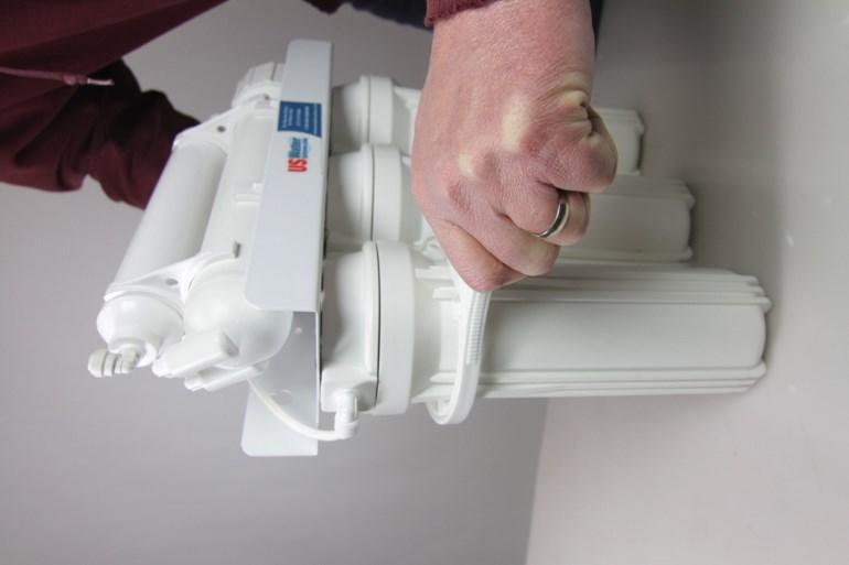
10 4. Remove the center sump and install the carbon filter in the sump. BE SURE that the rubber gasket is in place on BOTH sides of the carbon filter. 6. Remove the far left sump and install the chloramine filter (not pictured/yellow ends) in the sump. BE SURE that the rubber gasket is in place on BOTH sides of the carbon filter. 5. Tighten the center sump hand tight and secure it with the supplied filter wrench by turning it an additional 1/4-1/2 turn. 7. Tighten the far left sump hand tight and secure it with the supplied filter wrench by turning it an additional 1/4-1/2 turn. Page 10
11 F. Membrane Installation 1. Remove the 1/4 tubing from the membrane housing cap by pressing the collet on the elbow fitting toward the fitting. When the collet is flush with the fitting, the tubing will pull out of the fitting with little effort. Refer to connections instructions on Page Remove the membrane from the protective packaging and install it in the membrane housing. There are two O-rings on end of the middle membrane tube. Lightly lubricate these O-rings with the supplied silicone grease. 2. Use the supplied wrench to remove the membrane housing cap. 4. BE SURE the membrane is fully seated in the housing. If the membrane is fully seated, it will about 1/8-1/4 inset from being flush with the housing. Page 11

12 5. Lubricate the O-ring on the membrane housing and install the cap hand tight. Tighten the cap an additional 1/8-1/4 turn. Installation Instructions G. RO unit installation The RO unit is normally mounted to the sink cabinet sidewall, depending on where supply tank is to be located. Generally the unit is installed at the front of the cabinet and the tank at the rear. To mount the unit, elevate it at least 2 off the floor, level it and mark the location of mounting holes needed. Drill holes for mounting screws and install screws, allowing the mounting bracket slots to slip over them. NOTE: If the cabinet sidewalls are not solid, unit may sit on the floor with screws to keep it against the cabinet in a vertical position. The system doesn t have to be secured to the wall but it is a good practice. If the system is not mounted to the cabinet wall and the tubing is not cut short, the module and be removed from the cabinet during filter changes. 6. Push the 1/4 tubing back into the elbow fitting. BE SURE it is fully seated in the fitting or a leak could occur. H. Final tubing connections With all components in place, complete final tubing connections using these guidelines: Tubing should follow contour of the cabinets. Cut tubing to desired length using square cuts or a proper cutting devise. Make no sharp bends Under sink installations following installation diagram and the following procedures: 1. Connect the blue tubing to RO unit at the post carbon filter outlet fitting. Page 12


13 2. BE SURE the storage tank shutoff valve is in the closed position. Connect the open end of the green tubing from tank to the inlet tee on the post carbon filter on the RO system. 3. Connect orange tubing from the angle stop supply valve to RO unit at the sediment filter inlet fitting. 6. Connect the black line from the faucet to the open fitting on the UV chamber. 4. Connect the tubing from the drain saddle to the RO unit at the flow restrictor on the membrane. 7. DO NOT install DI Cartridges at this point. The system needs to be flushed prior to installing the DI filters. 5. Mount the DI system to the wall. Attach the blue tube from the RO system post carbon filter outlet elbow to the inlet tee on the DI filtration system. Page 13
14 System start-up Prior to start-up 1. Check all connections to be sure they are secure. 2. Turn on feed water valve and check for leaks. (Turn off and correct leaks if leaks occur.) 3. Close the valve (the tank should be closed from the previous step) on storage tank and open the faucet until a steady stream of water flows. Water will be flowing to the drain as well. This may take several minutes. 4. Once there is a steady stream of water coming from the faucet (about 1/8 in diameter) close the faucet and wait five minutes to see if any leaks result on the entire system (The initial water from the system may be discolored. This is normal). NOTE: BE PATIENT! It is very important that there is a steady stream (not drips) of water coming from the distribution valve before it is closed. If not, there could be air trapped in the system and it will not fill the tank properly. This can waste a lot of water. 5. If there are no leaks, open the storage tank valve allow the system to fill. Most systems will be full within 2 hours. The system is full when the water to the drain stops. Check for leaks with the system full and repair them accordingly. 1. Close the tank valve and the feed water valve and open the distribution valve to relieve the pressure on the system. 2. Remove the tank tubing from the tank valve and hold it over a bucket or pan. 3. Open the feed water valve and the distribution valve. 4. Allow the system to run until there is a stream of water coming from the tank tubing. 5. Once there is a steady stream coming from the tank tubing, push it back into the tank valve. BE SURE to push it in the tank valve completely or a leak could occur. 6. Allow the system to continue to operate until there is a steady stream coming from the distribution valve. 7. Once there is a steady stream coming from the faucet, close the distribution valve and open the tank valve. Then go to the aforementioned flushing procedure. Once the system has been purged of air and is fully operational, install the DI cartridges in the housings. 1. Shut off the water supply valve and the tank valve. Open the faucet and allow the pressure to release 2. Remove the DI filter sumps and install the DI cartridges. BE SURE to remove the plastic wrapper from the cartridges and make sure the upper rubber washer is in place. Flushing system and checking operation To make sure RO system is operating correctly, follow these simple procedures: 1. Open faucet and allow tank to completely drain (water will be discolored). 2. Close faucet and re-fill the system. 3. Allow system to process water for approximately 2-3 hours, at which point tank will be practically full. 4. Open faucet again and allow tank to empty for a second time. Do not use this water. 5. Wait another 2-3 hours to allow tank to re-fill. Air Purging 3. Install the cartridges in the housings and make sure the sump O-ring and rubber washer is in place on the cartridge. 4. Install the sumps and tighten hand tight. Snug them an additional 1/4 turn. 5. Turn on the supply water valve and the tank valve and allow the system to fill. 6. Flush the DI filters until the water quality stabilizes. NOTE: Water that sits in the DI sumps will start to lose quality. The DI filters should be flushed for 3-5 minutes or until the quality stabilizes each time the system is used. This is normal for DI water systems. If the tank doesn t fill, the tank tubing may have air in it. Typically the standard startup procedure will be sufficient but in some cases due to the water temperature and pressure, additional air bleeding must be performed. The following procedure will help bleed air from the system. Page 14


15 If there are no leaks on the system install the UV light. 1. Install the UV light in the chamber. BE SURE not to touch the UV bulb glass. Wear rubber gloves if possible. 3. Push the light cover onto the UV chamber to keep UV light from escaping. 2. Install the plug on the UV light bulb. Make sure it is fully attached and push the UV light bulb into the chamber. 4. Plug the UV ballast in a constantly energized 110V Outlet. This light should be on constantly. Page 15
16 Maintenance The RO system contains filters and membranes which must be replaced periodically for proper operation. Replacement Part Pre-filter (sediment) Pre-filters (activated carbon) R/O membrane Post filter (carbon) DI Filters UV Light Bulb NOTE: Filter change frequencies may be amended, depending on source water conditions. Sanitizing Filter Change Instructions Frequency Every 6-12 months. Every 6-12 months. Every 3-5 years Every 6-12 months. As Needed to Maintain Quality Every 12 Months 1. Turn off the feed water to the system and shut-off the icemaker power and water supply valve (if applicable). 2. Turn on the distribution valve to relive any pressure on the system and make sure water has stopped flowing out of the distribution valve. 3. Remove the membrane and all the lower vertical sump filters The post carbon filter can be left in place at this time. Use rubber gloves and store the membrane in water or a Ziploc bag to prevent damage or discard the membrane if it is being replaced. Remove the DI cartridges as well. 4. Use the included plastic syringe to collect 5ml of Sani- System solution from the packet and set aside. Pour the remainder of the packet of Sani-System directly into the sediment filter housing (where inlet feed line attaches). Reattach all filter housings and membrane caps. Do not install the filters at this time. Remove the tube that connects to the storage tank from the RO module and invert it to remove the water from the tube. If you have a fitting with a nut, disconnect it. If the fitting is a quick-connect type (push-to-fit) then you just push in the locking collet and pull the tube out. Inject all of the Sani-System solution from the plastic syringe into the line. Reattach tank tube. Make sure RO water distribution valve is closed and turn on water supply. 5. Allow system to fill with water. The time will vary depending on the water pressure. However, the system should be full within 5 10 minutes without the filters or membrane. Allow system to rest for 10 minutes. Open distribution valve and allow to drain for 10 minutes then close distribution valve. Allow the system to fill and rest for another 10 minutes, then open distribution valve again and allow system to flush for another 10 minutes. Shut off inlet supply and open distribution valve to depressurize the system. Remove the sumps and install the filters and membrane. 6. The white fiber-type filter is installed in the INLET (sediment) filter sump. Lubricate the o-ring at the top of the sump with a small amount of the silicone included. Tighten the filter sump hand tight, then using the wrench, turn an additional ¼ turn, but do not over tighten. 7. The carbon block filter(s) are installed into the next sump (for 3 & 4-Stage) or the next two sumps (for 5- Stage). Lubricate the O-ring at the top of the sump with a small amount of the silicone included. Be sure the rubber gaskets are in place on both sides of the carbon block filter. Tighten the filter sump hand tight, then using the wrench, turn an additional ¼ turn, but do not over tighten. 8. The inline filter is installed on the top of the membrane (does not apply on 3-Stage systems). The fittings in each end of the old post filter must be removed and wrapped with a couple of layers of ½ Teflon tape around the fitting (when looking at the threaded side of the fitting, always wrap the Teflon tape in a clockwise manner). The tee fitting will screw into the inlet side of the new filter and the elbow fitting to the outlet side. Re-install the tubing and make sure everything is sealed. 9. Turn on feed water valve and check for leaks. (Turn off and correct leaks if leaks occur.) 10. Close the valve on storage tank and open distribution valve until a steady stream of water flows. Water will be flowing to the drain as well. 11. Once there is a steady stream of water coming from the distribution valve (about 1/8 in diameter) close distribution valve and wait five minutes to see if any leaks result on the entire system (The initial water from the system may be discolored. This is normal). NOTE: BE PATIENT! It is very important that there is a steady stream (not drips) of water coming from the distribution valve before it is closed. If not, there could be air trapped in the system and it will not fill the tank properly. This can waste a lot of water. 12. If there are no leaks, open the storage tank valve allow the system to fill. Most systems will be full within 2 hours. The system is full when the water to the drain stops. Check for leaks with the system full and repair them accordingly. Page 16
17 Flushing system and checking operation To make sure RO system is operating correctly, follow these simple procedures: 1. Open distribution valve handle and allow tank to completely drain (water will be discolored and will have suds from the sanitizing solution). 2. Close distribution valve and re-fill the system. 3. Allow system to process water for approximately 2-3 hours, at which point tank will be practically full. 4. Open distribution valve again and allow tank to empty for a second time. Do not use this water. 5. Wait another 2-3 hours to allow tank to re-fill. Air Purging If the tank doesn t fill, the tank tubing may have air in it. Typically the standard startup procedure will be sufficient but in some cases due to the water temperature and pressure, additional air bleeding must be performed. The following procedure will help bleed air from the system. 1. Close the tank valve and the feed water valve and open the distribution valve to relieve the pressure on the system. 2. Remove the tank tubing from the tank valve and hold it over a bucket or pan. 3. Open the feed water valve and the distribution valve. 4. Allow the system to run until there is a stream of water coming from the tank tubing. 5. Once there is a steady stream coming from the tank tubing, push it back into the tank valve. BE SURE to push it in the tank valve completely or a leak could occur. 6. Allow the system to continue to operate until there is a steady stream coming from the distribution valve. 7. Once there is a steady stream coming from the distribution valve, close the distribution valve and open the tank valve. Then go to the flushing procedure above. NOTE: If no objectionable tastes are noticed after second tank draining, RO processed water is ready for use. Otherwise, drain tank and re-fill for a third time. Installation Instructions At this point supply line to ice maker connection (optional) may be opened. Once the system has been purged of air and is fully operational, install the DI cartridges in the housings. 1. Shut off the water supply valve and the tank valve. Open the distribution valve and allow the pressure to release 2. Remove the DI filter sumps and install the DI cartridges. BE SURE to remove the plastic wrapper from the cartridges and make sure the upper rubber washer is in place. 3. Install the cartridges in the housings and make sure the sump O-ring and rubber washer is in place on the cartridge. 4. Install the sumps and tighten hand tight. Snug them an additional 1/4 turn. 5. Turn on the supply water valve and the tank valve and allow the system to fill. 6. Flush the DI filters until the water quality stabilizes. NOTE: Water that sits in the DI sumps will start to lose quality. The DI filters should be flushed for 3-5 minutes or until the quality stabilizes each time the system is used. This is normal for DI water systems. Why the regular use of Sani-System is important. A reverse osmosis system should be sanitized regularly to maintain quality service levels. If the system is not properly maintained, bacteria can begin to grow and multiply wherever the water sits, including on the inside surfaces of tanks and hoses. Filling the system with impure water can also be a cause, but over time, bacteria grows even in chlorinated water. When water sits in a tank or hose, chlorine levels drop, reducing its chemical ability to prevent bacterial growth. Filters can also filter out chlorine, making the water more susceptible to bacterial growth. In addition, system equipment such as hoses, filters and canisters can harbor and help to support bacterial growth. Sani-System is the only EPA & NSF approved sanitizer for use in reverse osmosis units. It is proven to kill 99.9% of harmful bacteria without the use of chlorine, oxidizers or acids that can harm system parts. Sani-System maintains the performance of your reverse osmosis system and restores it to peak efficiency. Page 17
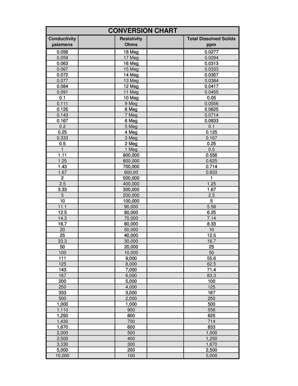
18 Water quality The formula is as follows: Water quality from an RO system is normally determined with a TDS Meter, which measures total dissolved solids in water, measuring conductivity. The results are normally measured in parts per million or milligrams per liter. Fewer dissolved solids results in higher quality water. The DI cartridges must be removed the check the membrane properly RO membranes are rated by the amount of dissolved solids they reject expressed as rejection percentage. For example: If feed water contains 100 ppm of dissolved solids and the product water after the membrane has 10 ppm of dissolved solids the rejection rate is 90%. Percent Rejection = (Feed H2O TDS - Product H2O TDS) x 100% Feed H 2 O The formula is as follows: RO membranes should operate between an 80-97% rejection rate. Once the rejection falls below 80%, the membrane must be replaced. Reject Ratio = PERCENT RECOVERY The percent recovery is another way to measure the amount of water produced compared to the amount of water which is actually used. The formula to determine percent recovery is as follows: Percent Recovery = NOTE: Product water rate is the sum of the feed water flow rate and reject water flow rate. For example: Product water rate =10 gpd Reject Rate Product Rate Product H 2 O Rate x 100% Feed H 2 O Rate Water production Reject water rate Feed water = 40 gpd = (10 gpd + 40 gpd) or 50 gpd PRODUCT WATER RATE Usable water production from an RO system is designated product water rate, produced on a daily basis. The rate is normally described in gallons per day (gpd) or milliliters per minute (ml/min). REJECT WATER RATE The flow of water to drain is designated as reject water rate, as measured in gallons per day (gpd) or milliliters per minute (ml/min). Using a graduated cylinder the formulas are: Percent Recovery = 20% Water pressure and temperature Product water quality and production of RO systems is dependent on pressure and temperature. Typically, RO membranes are treated at standard conditions of 77 F (25 C) and 60 psi (4 bar) discharging to atmosphere. In general, the higher the pressure differential and temperature, the greater the quality and quantity of water produced. These factors should be considered when sizing RO systems for a particular application. Milliliters per minute x 0.38 Ounces per minute x 11.2 = gallons per day = gallons per day REJECT RATIO The reject ratio is the amount of water produced compared to the amount of water flowing to drain. Page 18

19 Quick connect fittings Many RO systems utilize Quick Connect fittings. These userfriendly fittings provide superior performance and may be provided with this system. Proper use of these push-in fittings is shown below. Along with these fittings, all tubing selected must be of high quality and must be cut with a plastic tube cutter or sharp razor with a clean, square cut. How to make a connection: 1. Cut the tube square Cut the tube square. It is essential that the outside diameter be free from score marks and that burrs and sharp edges be removed before inserting into fitting. For soft thin walled tubing we recommend the use of tube inserts. 2. Insert tube Disconnecting Push in Collet and remove tube Installation Instructions To disconnect, ensure the system is depressurized before removing the tube. Push in collet squarely against face of fitting. With the collet held in this position, the tube can be removed. The fitting can be re-used. Should a leak occur at a fitting, the cause is generally defective tubing. To fix a leak, relieve pressure, release tubing, cut off at least 1/4 from the end (square cut), reattach the tubing and confirm the connection is leak free. Each time a new connection is made, it is advisable to cut off 1/4 from the end of the tubing using these fittings. Fitting grips before it seals. Ensure tube is pushed fully into the tube stop. 3. Push up to the tube stop Push the tube into the fitting to the tube stop. The collet (gripper) has stainless steel teeth which hold the tube firmly in position while the O-ring provides a permanent leak proof seal. 4. Pull to check secure Pull on the tube to check that it is secure. It is a good practice to test the system prior to leaving the site and/or before use. Page 19
20 (Green Tube) Page 20
21 Page 21
22 Page 22
23 Page 23
24 US WATER DENTAL OFFICE PURIFICATION SYSTEM THREE YEAR COVERAGE For three (3) years to the original purchaser, at the original residential place of installation of this US WATER DENTAL OFFICE PURIFICATION SYSTEM. US WATER SYSTEMS, INC. warrants the following: Storage Tank RO Module DI Module Free of all costs to you except transportation and labor charges, we warrant that we will replace or repair the storage tank, filter housings, and membrane housing, if for any reason it is found to be defective, because of faulty materials or workmanship. GENERAL PROVISIONS This warranty does not apply to any commercial or industrial installations or to any part of the reverse osmosis system which has been subjected to misuse, neglect, alteration or accident; or to any damage caused by fire, flood, freezing, Acts of God, or any other casualty, or if said system is damaged by anyone, or if the original serial numbers have been removed. Fouling or damage to the membrane or filters caused by iron, sulfur, bacterial iron, silt, sand, tannins, organics, bacteria, hot water or chlorine voids the warranty on the membrane.. US WATER DENTAL OFFICE PURIFICATION SYSTEM ONE YEAR COVERAGE We warrant that for one (1) year from the date of installation, we will replace any part not listed above at no charge to you except for transportation and standard labor charges, including the HM Digital monitor but will not cover the following items: Pre filters Post filters Reverse Osmosis Membrane THIS WARRANTY MAY BE TRANSFRRED TO A SUBSEQUENT OWNER WITH WRITTEN APPROVAL OF US WATER SYSTEMS, INC. AND PAYMENT OF STANDARD TRANSFER FEE. FOR YOUR RECORDS: Model Serial Date Installed These warranties are in lieu of all other warranties expressed or implied, and we do not authorize any person to assume for us any other obligation on the sale of this water conditioner. No responsibility is assumed for delays or failure to meet these warranties caused by strike, government regulations or other circumstances beyond the control of US WATER SYSTEMS, INC. TO OBTAIN WARRANTY SERVICE, CALL OR WRITE: US WATER SYSTEMS, INC COUNTRY CLUB ROAD INDIANAPOLIS, IN (317) OR ANY IMPLIED WARRANTIES OF FITNESS OR MERCHANTABILITY ARE LIMITED TO THE TERMS OF THIS EXPRESSED WARRANTY AND THERE ARE NO WARRANTIES WHICH EXTEND BEYOND THOSE HEREIN. US WATER SYSTEMS, INC. SHALL NOT BE LIABLE WHATSOEVER FOR ANY INCIDENTIAL AND/OR CONSEQUENTIAL DAMAGES. SOME STATES DO NOT ALLOW THE EXCLUSION OR LIMITATIONS OF INCIDENTAL OR CONSEQUENTIAL DAMAGES SO THE ABOVE LIMITATION MAY NOT APPLY TO YOU. THIS WARRANTY GIVES YOU SPECIFIC LEGAL RIGHTS, AND YOU MAY ALSO HAVE OTHER RIGHTS WHICH VARY FROM STATE TO STATE.
Owners Manual Models: 200-CHS-XXXX-XX. US Water Systems Cobalt Hyper-Safe Reverse Osmosis System. Visit us online at
 Visit us online at www.uswatersystems.com US Water Systems Cobalt Hyper-Safe Reverse Osmosis System Owners Manual Models: 200-CHS-XXXX-XX REVISION # 1.1 REVISION DATE January 5, 2017 US Water Systems Corporate
REVERSE OSMOSIS WATER FILTRATION SYSTEM MODEL EWR 4075 INSTRUCTION MANUAL
 REVERSE OSMOSIS WATER FILTRATION SYSTEM MODEL EWR 4075 INSTRUCTION MANUAL Excalibur Water Systems 142 Commerce Park Drive, Unit M & N Barrie, Ontario L4N 8W8 CANADA www.excaliburwater.com 2013.05.7446
Owners Manual Models: 075-AQF-CX. Aquatrol Backwashing Catalytic Carbon Filter. Visit us online at.
 Visit us online at www.uswatersystems.com Aquatrol Backwashing Catalytic Carbon Filter Owners Manual Models: 075-AQF-CX REVISION # 1.0 REVISION DATE October 11, 2017 US Water Systems, Inc. 1209 Country
REVERSE OSMOSIS INSTALLATION Watermark 4 Stage
 REVERSE OSMOSIS INSTALLATION Watermark 4 Stage BRIEF TECHNICAL ASPECT OF THE WATER TREATMENT SYSTEM The Filter Systems Australia Water Treatment System utilizes a process called reverse osmosis (RO). As
INSTALLATION INSTRUCTION & OWNER S MANUAL
 INSTALLATION INSTRUCTION & OWNER S MANUAL System Tested and Certified by NSF International against NSF/ANSI 42 for the reduction of Chlorine, Taste and Odor and 58 for the reduction of Total Dissolved
REVERSE OSMOSIS WATER FILTRATION SYSTEM MODEL EWR 3035 INSTRUCTION MANUAL
 REVERSE OSMOSIS WATER FILTRATION SYSTEM MODEL EWR 3035 INSTRUCTION MANUAL Excalibur Water Systems 142 Commerce Park Drive, Unit M & N Barrie, Ontario L4N 8W8 CANADA www.excaliburwater.com 3-Stage RO System
Pure Water Power Purification System 4-Stage RODI Operations Manual
 Pure Water Power Purification System 4-Stage RODI Operations Manual Flush Valve Lever Quick Disconnect for RO Water Testing Water Supply In Drain Hose Pure Water Out to Waterfed Pole New Machine Setup
Installation & Instruction Manual For Portable Series R.O. units:
 Installation & Instruction Manual For Portable Series R.O. units: Please read carefully before proceeding with installation *System components and appearance may vary from above image. REPLACEMENT AND
UltRo Dual Flow Reverse Osmosis Water System
 UltRo Dual Flow Reverse Osmosis Water System Congratulations on this great investment to your health. **IMPORTANT NOTE BEFORE YOU BEGIN** We recommend you call your local friendly plumber to ensure proper
FlashGARD HP Reverse Osmosis Filtration System Model Number FSTMO75 Part Number
 3M Water Filtration Products FlashGARD HP Reverse Osmosis Filtration System Model Number FSTMO75 Part Number 56123-06 Installer: Please leave this manual with owner/operator. End User: Please retain for
TABLE OF CONTENTS. Purchase Records... Introduction... Component List... Diagram... Specifications... Quick Connect Guide...
 TABLE OF CONTENTS Purchase Records... Introduction... Component List... Diagram... Specifications... Quick Connect Guide... 4 5 6 7 8 9 Installation STEP 1 Angle Stop Valve... Installation STEP 2 Drain
Installation and Instruction Manual for 6 stage ROCCS Requires Professional Installation
 Installation and Instruction Manual for 6 stage ROCCS Requires Professional Installation 2 2 1 Purchase Date: RO Serial Number: Tank Serial Number: Purchased From: Please read carefully before proceeding
INSTALLATION INSTRUCTION
 ULTIMATE Countertop REVERSE OSMOSIS SYSTEM INSTALLATION INSTRUCTION & OWNER S MANUAL Ver 2.4 www.freedrinkingwater.com All Rights Reserved APEC Water Systems Please keep this Owner s Manual for future
INSTALLATION, OPERATION AND MAINTENANCE MANUAL ZERO WASTE REVERSE OSMOSIS SYSTEM
 INSTALLATION, OPERATION AND MAINTENANCE MANUAL Warning Please read carefully before proceeding with installation. Your failure to follow a attached instructions or operating parameters may lead to the
IMPORTANT PLEASE READ BEFORE COMMENCING INSTALLATION
 IMPORTANT PLEASE READ BEFORE COMMENCING INSTALLATION This Fitting Guide is designed to assist in the Installation of your Reverse Osmosis System. Some of the parts that are supplied with each system may
Owner s Manual AMERICAN. LiquaGen 5 Stage (RO/DI) Aquarium Reef System. YEAR Y 1
 Aquarium Reef System. YEAR Y 1") Owner s Manual A NT HENTI AMERICAN Y 1 UT C WARR AR A 1-Y E LiquaGen 5 Stage (RO/DI) Aquarium Reef System YEAR MANUFACTURER WARRANTY Welcome to the LiquaGen experience and thank you for purchasing our
Owner s Manual A NT HENTI AMERICAN Y 1 UT C WARR AR A 1-Y E LiquaGen 5 Stage (RO/DI) Aquarium Reef System YEAR MANUFACTURER WARRANTY Welcome to the LiquaGen experience and thank you for purchasing our
Vessel Installation and Operating Manual
 For In-ground and Aboveground Pools Vessel Installation and Operating Manual Important Safety Information Please read this manual prior to installation. Nature 2 Express is designed to sanitize in-ground
Remineralized Reverse Osmosis System
 Remineralized Reverse Osmosis System Installation, Operation & Maintenance Manual Sept. 2016 Non-AG mineralpro.com MineralPRO Mfg. PO Box 1499 Parksville B.C. V9P-2H4, Canada T 250.586-6667 F 250.586-6670
GETZ EQUIPMENT INNOVATORS PART NO.: 9G59554 MODEL: MS 36 SC-R HYDROSTATIC TEST PUMP
 GETZ EQUIPMENT INNOVATORS PART NO.: 9G59554 MODEL: MS 36 SC-R HYDROSTATIC TEST PUMP LIMITED WARRANTY Getz Equipment Innovators warrants its products, and component parts of any product manufactured by
Installation and Operating Manual
 Safety Instructions Important Information Please read prior to installation ATTENTION! ELECTRICAL HAZARD FOR INGROUND POOLS AND ABOVEGROUND POOLS Installation and Operating Manual IMPORTANT Pool Owner,
Crystal Quest Voyager Series Inline Water Filter Systems INSTALLATION AND OPERATION GUIDE
 Crystal Quest Voyager Series Inline Water Filter Systems INSTALLATION AND OPERATION GUIDE ONLINE WARRANTY INFORMATION CrystalQuest.com/warranty.html Copyright 2018 Crystal Quest All rights reserved MADE
MineralPRO UF Installation, Operation, & Maintenance Manual
 MineralPRO UF Installation, Operation, & Maintenance Manual Mfg. Ltd. PO Box 1499 Parksville B.C.V9P-2H4 Canada T 250.586-6667 F 250.586-6670 MineralPRO Sept. 2016 Thank you for your purchase of a state
Owners Manual Installation Instructions. For Models PTRO-50
 Owners Manual Installation Instructions For Models PTRO-50 Table of Contents Page 2 Subject Page PURE TECH 1000 Features 3 What is Reverse Osmosis 4 System Overview 9 Installation 10 Warranty 14 Notes
3M Water Filtration Products
 3M Water Filtration Products Installation and Operation Instructions for ScaleGard TM HP Reverse Osmosis System Installer: Please leave this manual with owner/operator. Owner/Operator: Please retain for
ULTRA PURE SYSTEMS 625 GPD RODI INSTALLATION AND OPERATION MANUAL
 ULTRA PURE SYSTEMS 625 GPD RODI INSTALLATION AND OPERATION MANUAL Thank you for choosing UPS (Ultra-Pure Systems) for your RO/DI solution. We are confident you have made the right decision. This system
ULTRA PURE SYSTEMS 400 GPD RODI INSTALLATION AND OPERATION MANUAL
 ULTRA PURE SYSTEMS 400 GPD RODI INSTALLATION AND OPERATION MANUAL Thank you for choosing UPS (Ultra-Pure Systems) for your RO/DI solution. We are confident you have made the right decision. This system
Light Commercial Reverse Osmosis System. EE-1000 Manual
 Light Commercial Reverse Osmosis System EE-1000 Manual Nimbus Water Systems 41840 McAlby Court, Suite A Murrieta, CA 92562 800-451-9343 Fax 951-894-2801 www.nimbuswater.com Nimbus Water Systems 1 EE-1000
SpectraPure PUMPED RO SYSTEMS (PSP) User s Manual for PSP-1500 Systems
 User s Manual for PSP-1500 Systems") SpectraPure PUMPED RO SYSTEMS (PSP) User s Manual for PSP-1500 Systems 2 3 PSP-1500 SYSTEM DESCRIPTION Reverse Osmosis RO Reverse Osmosis utilizes the unique properties of a semi-permeable membrane to
SpectraPure PUMPED RO SYSTEMS (PSP) User s Manual for PSP-1500 Systems 2 3 PSP-1500 SYSTEM DESCRIPTION Reverse Osmosis RO Reverse Osmosis utilizes the unique properties of a semi-permeable membrane to
INSTALLATION INSTRUCTIONS FOR GRT75-PF-RFS PET FOUNTAIN
 INSTALLATION INSTRUCTIONS FOR GRT75-PF-RFS PET FOUNTAIN Important: Read all instructions and refer to local codes prior to installation. l Local soil conditions may require more gravel for drainage. l
MN-800-TF REVERSE OSMOSIS TREATMENT SYSTEM OWNERS MANUAL
 MN-800-TF REVERSE OSMOSIS TREATMENT SYSTEM OWNERS MANUAL Nimbus Water Systems 41840 McAlby Court, Suite A Murrieta, CA 92562-7036 800-451-9343 THE NIMBUS MN-800 TF REVERSE OSMOSIS TREATMENT SYSTEM TABLE
ULTIMATE REVERSE OSMOSIS SYSTEM
 ULTIMATE REVERSE OSMOSIS SYSTEM INSTALLATION INSTRUCTION & OWNER S MANUAL Ver 3.7 www.freedrinkingwater.com All Rights Reserved APEC Water Systems Please keep this Owner s Manual for future reference.
Zoi Series. RO System Reverse Osmosis Water Filtration System. DFK-Alpha * MB F. Core System Filter Set. Replacement Membrane
 Incoming TDS/Total Dissolved Solids not to exceed 2000 PPM. Use of Vaseline or petroleum based lubricants will also void the warranty. How Do I Receive Warranty Service? If your system is found to be defective,
ULTIMATE REVERSE OSMOSIS SYSTEM
 ULTIMATE REVERSE OSMOSIS SYSTEM RO-PH90 INSTALLATION INSTRUCTION & OWNER S MANUAL Ver 1.1 www.freedrinkingwater.comr All Rights Reserved APEC Water Systems Please keep this Owner s Manual for future reference.
INSTALLATION & START-UP INSTRUCTIONS. Clack WS1 & WS1.25 METER WATER SOFTENER SYSTEMS
 INSTALLATION & START-UP INSTRUCTIONS Clack WS1 & WS1.25 METER WATER SOFTENER SYSTEMS 1999-2009 QualityWaterForLess.com - 1 - info@qualitywaterforless.com Preface: Thank you for your purchase of a new Water
Sterisil Ac+ Installation & Operating Manual
 Sterisil Ac+ Installation & Operating Manual 719 622 7200 Sterisil.com Arbor Dental Associates 2 Table of Contents Introduction 4 Sterisil Ac + Features 5 Installation Instructions 6 Maintenance 10 Troubleshooting
PENTEK GRO STAGE REVERSE OSMOSIS WATER FILTRATION SYSTEM INSTALLATION AND OPERATION MANUAL
 PENTEK GRO-2550 4-STAGE REVERSE OSMOSIS WATER FILTRATION SYSTEM INSTALLATION AND OPERATION MANUAL 2016 Pentair Residential Filtration, LLC waterpurification.pentair.com IMPORTANT: efore installing this
Installation, Operation and Maintenance Manual
 Installation, Operation and Maintenance Manual Model H2F H2Flow Anti-Scale System Chemical-Free, Salt-Free Scale Prevention Introduction The H2Flow Anti-Scale System will condition the tap water providing
ROES-PH75 INSTALLATION INSTRUCTION & OWNER S MANUAL
 ESSENCE REVERSE OSMOSIS SYSTEM ROES-PH75 INSTALLATION INSTRUCTION & OWNER S MANUAL Ver 1.1 www.freedrinkingwater.com All Rights Reserved APEC Water Systems Please keep this Owner s Manual for future reference.
ESSENCE REVERSE OSMOSIS SYSTEM INSTALLATION INSTRUCTION
 ESSENCE REVERSE OSMOSIS SYSTEM INSTALLATION INSTRUCTION & OWNER S MANUAL Ver 2.3 www.freedrinkingwater.com All Rights Reserved APEC Water Systems Please keep this Owner s Manual for future reference.
G7S Hand Pump Owner s Manual
 G7S Hand Pump Owner s Manual Copyright Air Venturi 2018 Version 4-18 Specifications 24.80 inches long closed 43.31 inches long extended 4500 psi/310 bar max pressure Features Integral manometer (pressure
Installation Guide & Owner s Manual. Model V4700. Water Filtration for Dental & Medical Instrument Washing Equipment
 Installation Guide & Owner s Manual Model V4700 Water Filtration for Dental & Medical Instrument Washing Equipment Safety Guides & General Information Please read this manual completely before attempting
Installation, Operation, and Maintenance Manual
 Installation, Operation, and Maintenance Manual Product Preservers Anti-Scale System Chemical-Free, Salt-Free Scale Prevention Introduction The Product Preservers Anti-Scale System will condition the tap
INSTALLATION & START-UP INSTRUCTIONS FLECK 9100SXT METER TWIN ALTERNATING WATER SOFTENER SYSTEMS
 INSTALLATION & START-UP INSTRUCTIONS FLECK 9100SXT METER TWIN ALTERNATING WATER SOFTENER SYSTEMS 1999-2007 QualityWaterForLess.com - 1 - info@qualitywaterforless.com Preface: Thank you for your purchase
Compact Triple Cabinet Outlet Station Model B Installation and Operating Instructions
 PORTER Parker Hannifin Corporation Porter Instrument Division 245 Township Line Rd. P.O. Box 907 Hatfield, PA 19440-0907 USA (215) 723-4000 / fax (215) 723-5106 Compact Triple Cabinet Outlet Station Model
ULTRA REVERSE OSMOSIS SYSTEM
 ULTRA REVERSE OSMOSIS SYSTEM INSTALLATION INSTRUCTION Free Drinking Water.com Please keep this Owner s Manual for future reference. It contains useful information on how to maintain and care for your APEC
Customer Support Troublshooting
 PB-TLRO4H50T - 4 Stage Reverse Osmosis Water Filtration System 1 of 6 Customer Support Troublshooting The number one, essential, tool to good customer service is your SMILE. Even if your customer can t
Compact Triple Cabinet Outlet Station Model Installation and Operating Instructions
 Compact Triple Cabinet Outlet Station Model 6258-1 Installation and Operating Instructions The Porter Compact Triple Outlet Station (6258-1) provides a quick, safe, and reliable method of connection to
Please Keep this Instruction Manual for future reference TABLE OF CONTENT
 Please Keep this Instruction Manual for future reference It contains important information on how to maintain and care for your LiquaGen water filter system Warning : Using a qualified installer is recommended.
FLUSHMATE FLUSHOMETER - TANK SYSTEM. 501-A Series. Owner s Service Manual. 501-A Series
 Owner s Service Manual 501-A Series FLUSHMATE FLUSHOMETER - TANK SYSTEM 501-A Series A Division of Sloan Valve Company 30075 Research Drive New Hudson, MI 48165 800-533-3450 248-446-5300 http://www.flushmate.com
INSTALLATION INSTRUCTIONS
 INSTALLATION INSTRUCTIONS HIGH PRESSURE PUMP To minimize vibration, it is best to build brackets on the motor itself, similar to alternator brackets. Use cardboard to construct a pattern first before making
1020 Industrial Drive, Orlinda, TN fax
 Operation Manual Ultrafiltration for High Purity Distribution K-A-HPTUF Series 615-654-4441 sales@specialtyh2o.com 615-654-4449 fax TABLE OF CONTENTS Section 1 GENERAL 1.1 Warnings and Cautions... 1 1.2
NB/NBR NITROGEN BOOSTER FOR AVIATION SERVICE
 NB/NBR NITROGEN BOOSTER FOR AVIATION SERVICE INSTALLATION, OPERATION & MAINTENANCE MANUAL INTERFACE DEVICES, INC. 230 Depot Road, Milford, CT 06460 Ph: (203) 878-4648, Fx: (203) 882-0885, E-mail: info@interfacedevices.com
444C DUAL PERFORMANCE VALUE PACK
 (Chrome) PART NO. 44432 IMPORTANT: It is essential that you and any other operator of this product read and understand the contents of this manual before installing and using this product. SAVE THIS MANUAL
UsER manual for Watersens ph -REDOX
 UsER manual for Watersens -REDOX Cl 8 1 2 6 3 3 7 7 4 4 4 4 Parts List 1 Redox Probe 1 x 2 PH Probe 1 x 5 Tube Weight 2 x 6 Connection Valve 1 x chlorine 3 Chlorine and Pumps 2 x 7 Dosing Valve 2 x 5 5
FLUSHMATE III FLUSHMATE FLUSHOMETER - TANK SYSTEM. Owner s Service Manual. 503 Series. 503 Series
 Owner s Service Manual 503 Series FLUSHMATE III FLUSHOMETER - TANK SYSTEM 503 Series FLUSHMATE A Division of Sloan Valve Company 30075 Research Drive New Hudson, MI 48165 800-533-3450 248-446-5300 http://www.flushmate.com
Yoke Block Instruction Manual
 Yoke Block Instruction Manual ! WARNING IMPORTANT: READ MANUAL COMPLETELY BEFORE OPERATING THIS DEVICE This manual contains instructions on periodically required checks to be performed by the user. These
Culligan Aqua-Cleer. Advanced Drinking Water Systems. Installation, Operation & Service Instructions with Parts List.
 Cat. No. 01020219 Rev. E 7/30/10 DCO # 011897 Installation, Operation & Service Instructions with Parts List Culligan Aqua-Cleer Advanced Drinking Water Systems Models from 2010 2010 Culligan International
Model PSI Compressor with 3-Gallon Air Tank 12VDC
 Model 6350 150 PSI Compressor with 3-Gallon Air Tank 12VDC IMPORTANT: It is essential that you and any other operator of this product read and understandd the contents of this manual before installing
Yoke Block Instruction Manual
 Yoke Block Instruction Manual ! WARNING IMPORTANT: READ MANUAL COMPLETELY BEFORE OPERATING THIS DEVICE This manual contains instructions on periodically required checks to be performed by the user. These
Hot Tapping Machine. OPERATIONS MANUAL and OPERATING INSTRUCTIONS
 262-2040 Hot Tapping Machine For performing 1/4 6 Hot taps 285 psi or less. Municipal Water, Sewage, & Building Services Use OPERATIONS MANUAL and OPERATING INSTRUCTIONS WARNING: These instructions are
400C & 450C DUAL PERFORMANCE VALUE PACKS
 (Chrome) PART NO. 40013 (Silver) PART NO. 45012 (Chrome) PART NO. 45013 IMPORTANT: It is essential that you and any other operator of this product read and understand the contents of this manual before
PoolNaturally. Pure. Simple. Genius. Installation and Product Use Instructions In ground and above ground pools
 PoolNaturally Pure. Simple. Genius. Installation and Product Use Instructions In ground and above ground pools V2.31 Installation Diagrams: (Installation can be done either before or after the pump. Shown
OWNER S MANUAL. Table of Contents
 OWNER S MANUAL Table of Contents Features Page 2 Components and Functions Page 3 Installation Procedures Pages 4-6 Instructions for Use Page 7 Routine Maintenance Page 8 Notices and Warnings Page 9 Technical
ROPV R40 E Series User Manual
 HARBIN ROPV INDUSTRY DEVELOPMENT CENTER ROPV R40 E Series User Manual For Use with the Following ROPV Pressure Vessel Models: R40 300E R40 450E Headquarters Tel:(+86)451-82267301 Fax:(+86)451-82267303
WATER HEATER THERMAL EXPANSION TANKS Owner s Manual. Safety Instructions Installation Maintenance Warranty. Models: 2-5 Gallon Capacity
 WATER HEATER THERMAL EXPANSION TANKS Owner s Manual Safety Instructions Installation Maintenance Warranty Models: 2-5 Gallon Capacity Thank You for purchasing this Thermal Expansion Tank. Properly installed
ATD /8 x 50 Retractable Air Hose Reel Owner s Manual
 ATD-31166 3/8 x 50 Retractable Air Hose Reel Owner s Manual Features Heavy-gauge, all-steel reel assembly 8-position ratchet mechanism locks reel at desired hose length 5-position adjustable roller outlet
Drinking Water Kit with Non-Air Gap Faucet for RO and RO/DI Systems (Including -MF Systems)
") Drinking Water Kit with Non-Air Gap Faucet for RO and RO/DI Systems (Including -MF Systems) INSTRUCTIONS WARNING Please read carefully before proceeding with installation. Failure to follow any attached
Drinking Water Kit with Non-Air Gap Faucet for RO and RO/DI Systems (Including -MF Systems) INSTRUCTIONS WARNING Please read carefully before proceeding with installation. Failure to follow any attached
Pressure Dump Valve Service Kit for Series 3000 Units
 Instruction Sheet Pressure Dump Valve Service Kit for Series 000 Units. Overview The Nordson pressure dump valve is used to relieve hydraulic pressure instantly in Series 00, 400, 500, and 700 applicator
SSFU SUPER SPRAYFAST UNIVERSAL ADHESIVE APPLICATOR
 S S F U SSFU SUPER SPRAYFAST UNIVERSAL ADHESIVE APPLICATOR MACHINERY DIVISION OWNER S MANUAL UNIT INSTRUCTIONS Please follow all SSFU Safety Instructions. Contact your Duro Dyne Tech Service if you have
TECHNICAL DATA MAINTENANCE AIR COMPRESSOR MODEL G-1
 Dry 131h 1. DESCRIPTION The Viking Model G-1 Maintenance Air Compressor is an electric motor-driven, aircooled, single-stage, oil-less compressor. The unit is equipped with a check valve and provides a
Accu-Tab Systems 2000 P Series by Axiall Corporation
 Accu-Tab Systems 2000 P Series by Axiall Corporation Installation and Operating Instructions Models 2075 P 2150 P For NSF/ANSI-Standard 61 NSF STANDARD 61 applications use NSF/ANSI Standard 60 listed Axiall
Operation Manual. Carbon Filtration Industrial Drive, Orlinda, TN fax
 Operation Manual Carbon Filtration 615-654-4441 sales@specialtyh2o.com 615-654-4449 fax TABLE OF CONTENTS Section 1 GENERAL 1.1 Warnings and Cautions... 1 1.2 Theory of Operation... 2 1.3 System Illustration...
SElECTING A MOUNTING location OPERATING SPECIFICATIONS* * For individual cartridge specifications, refer to cartridge literature.
 by~ Figure 1 - Follett Single System Figure 2 - Follett Twin System SElECTING A MOUNTING location 1. Give consideration to the weight of the unit when operating (filled with water). Operating weights of
Halsey Taylor Owners Manual 4410 Freeze Resistant Tubular Fountain STOP!
 Halsey Taylor Owners Manual 4410 Freeze Resistant Tubular Fountain STOP! PLEASE READ THE FOLLOWING INFORMATION. ITALLATION ITRUCTIO FOR THE 4410FR FTN. WITH 97243C SINGLE VALVE CONTROL ASSEMBLY ARE LOCATED
Installation, Operation, and Maintenance Manual
 Installation, Operation, and Maintenance Manual Welker The information in this manual has been carefully checked for accuracy and is intended to be used as a guide for the installation, operation, and
PC7-C Flowmeter O2/N2O Sedation Unit Instruction Manual
 PC7-C Flowmeter O2/N2O Sedation Unit Instruction Manual ! WARNING IMPORTANT: READ MANUAL COMPLETELY BEFORE OPERATING THIS DEVICE This manual contains instructions on periodically required checks to be
Installation Instructions
 Installation Instructions S65-135 (Circular) S65-136 (Semi-Circular) Air Valve Retrofit For Non-Sectional Classic Washfountain Table of Contents.......................2-6 Metering Air Valve Parts List....................6
Purifier for Vinyl Lined Pools
 Purifier for Vinyl Lined Pools Operating Manual READ THE LABEL AND OPERATOR S MANUAL BEFORE USING Pool owner, save this manual! Builders, leave this manual with the pool owner! We ask you to take the time
Pressure Dump Valve Service Kit for Series 2300 Units
 Instruction Sheet Pressure Dump Valve Service Kit for Series 00 Units. Overview The Nordson pressure dump valve is used to relieve hydraulic pressure instantly in Series 00 applicator tanks when the unit
RG1200 Service and Repair Manual
 Dive Rite RG 1200 Regulator Service and Repair Manual Page 1 Text and Photography by Pete Nawrocky Copyright ( ) 1999-2000, Lamartek, Inc., dba Dive Rite RG1200 Service and Repair Manual First Stage.........................................
GETZ EQUIPMENT INNOVATORS PART No. 4G59678 CARBON DIOXIDE MINI PUMP FOR EXTINGUISHER SERVICE (Revised )
") GETZ EQUIPMENT INNOVATORS PART No. 4G59678 CARBON DIOXIDE MINI PUMP FOR EXTINGUISHER SERVICE (Revised 11-24-10) 2320 Lakecrest Drive, Pekin IL 61554 PH. (888) 747-4389 Fax (309) 495-0625 Website: www.getzequipment.com
GETZ EQUIPMENT INNOVATORS PART No. 4G59678 CARBON DIOXIDE MINI PUMP FOR EXTINGUISHER SERVICE (Revised 11-24-10) 2320 Lakecrest Drive, Pekin IL 61554 PH. (888) 747-4389 Fax (309) 495-0625 Website: www.getzequipment.com
453 Series Steam Heated Vaporizing Regulator
 ADI 0453A Certified ISO 9001:2000 453 Series Steam Heated Vaporizing Regulator INSTALLATION AND OPERATION INSTRUCTIONS Before Installing or Operating, Read and Comply with These Instructions Controls Corporation
User Instruction Manual
 User Instruction Manual 4500 psi Air Compressor Ver 2, 1.18 Contents Parts Included...3 Assembly Instructions...3-5 Operation Instructions...6-7 Oil Change Intervals...8 Air Filter Replacement...9 Setting
PROPORTIONING VALVE. Model 150 INSTRUCTION MANUAL. March 2017 IMS Company Stafford Road
 PROPORTIONING VALVE Model 150 INSTRUCTION MANUAL March 2017 IMS Company 10373 Stafford Road Telephone: (440) 543-1615 Fax: (440) 543-1069 Email: sales@imscompany.com 1 Introduction IMS Company reserves
BS Series Basket Strainer
 BS Series Basket Strainer Operating, Installation, & Maintenance Manual Corrosion Resistant Fluid and Air Handling Systems. Dated 04-26-12 PRESSURE DROP SIMTECH strainers are engineered to offer the lowest
Water Weir Flow Controller. Introduction. Safety Precautions. Mounting the Hardware
 57007-88 Introduction Safety Precautions This instruction sheet describes how to set up and use the Hach (Figure 1). A water weir is a device that raises or diverts water to regulate the flow. Hach s water
Freedom8 ShoeBox Compressor Manual
 Freedom8 ShoeBox Compressor Manual Warning!! This product is not a toy! Use or misuse can cause severe injury or death! Use only with adult supervision. This unit is only to be used with tanks, hoses and
J Air and Water Kit Instructions Part# 02584
 J Air and Water Kit Instructions Part# 02584 Unpacking Please open and inspect your package upon receipt. Your package was packed with great care and all the necessary packing materials to arrive to you
SPECIFICATIONS Type: Twin stack, single phase Tank: 4 gallon Air Output: PSI; PSI Max PSI: 125 PSI HP: 1.
 2 GALLON TWIN STACK AIR COMPRESSOR Model: 9526 DO NOT RETURN TO STORE. Please CALL 800-348-5004 for parts and service. CALIFORNIA PROPOSITION 65 WARNING: You can create dust when you cut, sand, drill or
Halsey Taylor Owners Manual STOP!
 Halsey Taylor Owners Manual 4710 Freeze Resistant Floor Mounted Steel Fountain STOP! PLEASE READ THE FOLLOWING INFORMATION. ITALLATION ITRUCTIO FOR THE 4710FR FTN. WITH 97243C SINGLE VALVE CONTROL ASSEMBLY
Installation Instructions
 Installation Instructions COLONY SOFT 7.0 Single Control Lavatory Faucet with Speed Connect Drain Congratulations on purchasing your American Standard faucet with the Speed Connect drain, a feature found
CS Controlled Dissolved Gas assembly with optional CS Air Aspirator assembly. Installation and Operation information
 CS-425-01 Controlled Dissolved Gas assembly with optional CS-603-01 Air Aspirator assembly Installation and Operation information Serial # CS-XXX Date of shipment:, 2005 Shipped to: Purchase order #: xxxxxxx
INSERT FITTINGS INSERT FITTINGS
 Insert Tee Insert x Female Tee Insert Elbow Insert x Male Elbow Insert Coupling Insert x Male Adapter Insert x Female Adapter Insert Plug POLY and NYLON FITTINGS For use with Poly Tubing Fitting 1/2 3/4
Model B-1 Pipe Line Strainer 3, 4, 6 & 8 Inch (DN80, DN100, DN150 & DN200) 175 psi (12,1 bar) General Description. Technical Data
 175 psi (12,1 bar) General Description. Technical Data") Technical Services: Tel: (800) 381-312 / Fax: (800) 71-5500 Customer Service/Sales: Tel: (215) 362-0700 / (800) 523-6512 Fax: (215) 362-5385 Model B-1 Pipe Line Strainer 3,, 6 & 8 Inch (DN80, DN100, DN150
Technical Services: Tel: (800) 381-312 / Fax: (800) 71-5500 Customer Service/Sales: Tel: (215) 362-0700 / (800) 523-6512 Fax: (215) 362-5385 Model B-1 Pipe Line Strainer 3,, 6 & 8 Inch (DN80, DN100, DN150
2 GALLON TWIN STACK AIR COMPRESSOR W/ HOSE REEL
 2 GALLON TWIN STACK AIR COMPRESSOR W/ HOSE REEL Model: 52024 CALIFORNIA PROPOSITION 65 WARNING: You can create dust when you cut, sand, drill or grind materials such as wood, paint, metal, concrete, cement,
ULTRA-LIGHT DUTY ONBOARD AIR SYSTEM
 ULTRA-LIGHT DUTY ONBOARD AIR SYSTEM PART NO. 10000 IMPORTANT: It is essential that you and any other operator of this product read and understand the contents of this manual before installing and using
Advanced Reverse Osmosis Water Filtration System
 KEEP THIS MANUAL Advanced Reverse Osmosis Water Filtration System Installation and Operating Instructions Models RO-3000 and RO-3500 (with electronic TDS monitor) Operating Specifications IMPORTANT! efore
RARS5000 AIR BODY SAW OWNER S OPERATING MANUAL
 RARS5000 AIR BODY SAW OWNER S OPERATING MANUAL DESCRIPTION 1. No mar 2. No mar tip 3. Housing grip 4. Trigger 5. Air inlet 6. Air inlet plug 7. Plastic board Important! It is essential that you read the
NXT 4 Pure Water System
 NXT 4 Pure Water System Effective December, 2018 Pure Water Window Cleaning System Operation and Maintenance Manual Overview Congratulations on your purchase. Thank you for purchasing the NXT 4 Pure Water
250C-IG COMPRESSOR KIT 12V PART NO C-IG COMPRESSOR KIT 24V PART NO
 250C-IG COMPRESSOR KIT 12V PART NO. 25050 250C-IG COMPRESSOR KIT 24V PART NO. 25058 IMPORTANT: It is essential that you and any other operator of this product read and understand the contents of this manual