Owners Manual Installation Instructions. For Models PTRO-50
|
|
|
- Dwayne Wilcox
- 5 years ago
- Views:
Transcription


1 Owners Manual Installation Instructions For Models PTRO-50

2 Table of Contents Page 2 Subject Page PURE TECH 1000 Features 3 What is Reverse Osmosis 4 System Overview 9 Installation 10 Warranty 14 Notes 15 P.O. Box Ormond Beach, FL (PURE) 7873 Office (PURE) 7873 Fax Copyright 2003 all rights reserved
3 PURE TECH 1000 Flow Diagram Page 3 Water line from cold water inlet Clean water faucet PURE TECH 1000 Drain line to sink drain Pressure Tank
4 What is Reverse Osmosis Page 4 Osmosis is a natural process, known for over 200 years, on which reverse osmosis systems are based. The walls of living cells are natural membranes. This means that the membrane is selective, some materials can pass through, others cannot. Figure 1 illustrates osmosis and the selectivity of the membrane. The semi-permeable nature of the membrane allows the water to pass much more readily than the dissolved minerals. Since the water in the less concentrated solution seeks to dilute the more concentrated solution, the water passage through the membrane generates a noticeable head difference between the two solutions. This head difference is a measure of the concentration difference of the two solutions and is referred to as the osmotic pressure difference. This head pressure, converted to the familiar pressure units of pounds per square inch (2.31 feet of water head equals 1 psi), allows the observation of a valuable rule of thumb. That is, that each 100 mg/l total dissolved difference is equal to approximately 1 psi osmotic pressure difference. When a pressure is applied to the concentrated solution which is great that the osmotic pressure difference, the direction of water passage through the membrane is reversed and the process that we refer to as reverse osmosis is established. That is, the membrane's ability to selectively pass water is unchanged, only the direction of the water flow is changed. Thus, as shown in Figure 2, a water treatment technique in which the water is being separated from the dissolved minerals is demonstrated.
5 What is Reverse Osmosis cont. Page 5 Were the membrane to act as a perfect separator, the permeate would contain 0-mg/L total dissolved solids, no matter what the concentration on the feed side of the system. This is not the case, however. And, in fact, let us consider, for the sake of illustration, 90% rejection to be an average operating condition. By considering the mechanism of salt and water passage through the membrane, it will be clear why complete salt elimination is not possible and how operating conditions can effect permeate quality and quantity. The membrane's ability to hold back salts while allowing water to pass is based on the fact that the salts are in solution as ions, that is, charged particles. The dissolved salts are in solution as cat ions, with a positive charge, and as anions, with a negative charge. A descriptive analogy of what is happening is to consider the membrane to be a mirror. As the charged particles, ions, approach the membrane, they are repelled by a reflection of their own charge. That is, similar charges repel, just as similar magnetic poles repel each other. Therefore, the layer of water immediately adjacent to the membrane is void of charged particle, and it is this water which will subsequently diffuse through the pores and be delivered as permeate. Since the anions and citations are constantly moving around in solution, sometimes they are near enough to each other to be attracted to one another, thus canceling their individual charges. Without a net charge, these particles are free to pass through the membrane. Although Figure 2 was sufficient to illustrate the basic RO process, the feed and concentrate ports added in Figure 3 are necessary to illustrate a continuously operating RO system. In order to keep the membrane from fouling it is important to continually flush the brine side. As the water is squeezed through the membrane, leaving most of the salts behind, the brine side solution becomes increasingly concentrated. Without the reject flow to drain, the brine side mineral concentration would eventually exceed the solubility limits of the salts present and they would precipitate, forming a scale on the membrane. To avoid excessive brine side concentrations, the permeate volume recovered, in a low pressure system, is usually kept in the range of 1- to 30 percent of the feed stream volume. For example, if for each five gallons of water fed to the membrane, one gallon of permeate is recovered, the membrane is operating at 20% recovery.

6 What is Reverse Osmosis cont. Page 6 REVERSE OSMOSIS MEMBRANES Construction The semi-permeable membrane used RO systems are cast polymer films of asymmetric density. That is, they have a dense barrier layer which is very thin, perhaps 10 millionths of an inch, supported on a more porous substrate a few thousandths of an inch thick. Figure 4 illustrates the different densities in the cross section of the membrane. Configurations Different configurations of membranes have been devised, each offering certain advantages. The most popular membrane configuration is the spiral wound, shown below in Figure 5. These are assembled by folding a sheet of membrane over a tube, referred to as the product tube, and trapping a screen between the two halves of the membrane. The membrane is bonded to the tube and glued together along the three open edges. Another spacer screen is laid on the membrane and the whole sandwich is rolled tightly around the product tube and then bound with tape to hold it together. This method of packaging membrane provides considerably more surface area per module than the tubular. However, since the feed water must wind its way through the path created by the spacer screen, dirt particles can be easily trapped, so 5 micron pre-filtration is generally recommended. Reverse Osmosis Operation The general operation of all RO modules is the same. The feed stream is supplied to the membrane and split into the permeate which has diffused through the membrane, and the concentrate which passes over the membrane, carrying away the minerals to waste.
7 What is Reverse Osmosis cont. Page 7 Low Pressure Systems Low pressure RO operation generally refers to feed pressures of less than 100 psig. This includes most of the equipment capable of being installed under the kitchen sink and those referred to as counter top modules. Figures 6 and 7 define the elements commonly found in these systems and their arrangements. Although for the counter top Reverse Osmosis modules and some permanently installed units, the storage tanks are maintained at atmospheric pressure - the majority of underthe-sink installations utilize accumulator storage vessels. As water is added to the tank, the air charge is compressed and thus the pressure in the tank rises. It is this elevated pressure that is used to propel the drinking water to the faucet. The pressure in the tank also, however, acts as a back pressure on the membrane, and as tank pressure increases, the differential pressure across the membrane decreases. Recalling the expressions for water and salt transport across the membrane, as the tank pressure rises, the water production rate drops and yet the salt passage continues unaffected. Thus the quality of the water being delivered drops significantly if the differential pressure is allowed to become too low. Therefore, most equipment included some provision for limiting the storage tank pressure to some value less than line pressure. A ratio of two thirds is a commonly chosen limit, and may be done for a continuous flowing system as shown in Figure 8.
8 What is Reverse Osmosis cont. Page 8 When the storage tank has been filled to the point at which its pressure equals two thirds of line pressure, the permeate is diverted to drain. To conserve water consumption in reverse osmosis devices another type of control called "shutdown" is employed in the design using a shutoff valves and is illustrated in Figure 9. At the designed-in, present ration, the storage tank pressure will close the valve and prevent further feed to the system. The valve will open again when sufficient pressure reduction is sensed at the storage tank. Whatever means is used to accomplish shut down, the end result is that the differential pressure across the membrane is eliminated so that water production ceases. Unless provision is made to eliminate the dissolved mineral concentration difference across the membrane, salt passage will continue, creating a high TDS water on the permeate side of the membrane. This phenomena is commonly referred to as a TDS creep
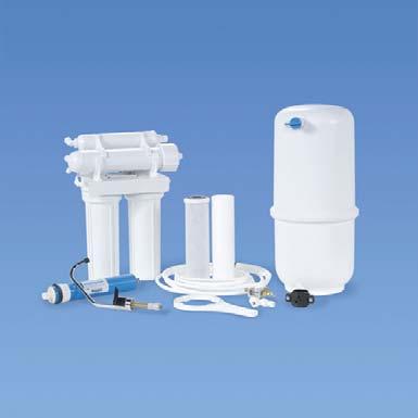
9 System Overview Page 9 Your Drinking Water System has been tested to ensure it will operate correctly. The following periodic maintenance is recommended so your system will provide years of trouble-free service: Replacement parts Pre-filters (sediment) Post-filters (activated carbon) Replacement Every 6 mos. Every 6 mos. Components The following components make up you drinking water system. Pre-filter (s) -sediment removes larger particles such as sand, silt, rust and scale. Post-filter activated carbon removes chlorine in the feed water to protect the
10 Installation Page 10 Note: All plumbing must be completed in accordance with state and local plumbing codes. Some municipalities may require installation by a licensed plumber. Check local authority prior to installation. 1. Faucet Installation: If the sink has a sprayer it may be disconnected for faucet installation. (Installing dealers should discuss the with customers.) A pipe cap or plug will be necessary to seal the sprayer connection. To make the faucet mounting hole (if sprayer or second hole is not used), check below to make sure the drill does not interfere with anything below. Center punch a small indent at the desired faucet location. (2 flat surface is required, not exceeding 1-1/4 in thickness.) Drill the required pilot hole for the chassis punch and tighten nut to cut the desired hole size. Clean up sharp edges. The faucet should be positioned so it empties into the sink and the spout swivels freely for convenience. If sink has a hole that can accommodate the faucet, no drilling is required. Proceed with mounting faucet. Porcelain, Enamel, Ceramic on Metal or Cast Iron: Precaution must be taken to penetrate the porcelain through to the metal base and prevent it from chipping or scratching. Tools Required: Variable Speed Drill Relton porcelain cutter tool set (7/8 or alternative size, 9/16 ) Plumber s putty Procedures: 1. Mark the center for the 7/8 hole. Form shallow putty around hole area and fill with enough water to lubricate carbide drill bit. 2. Carefully drill pilot hole through all layers. (Use light pressure and slow speed.) 3. Insert pilot tip of spring-loaded porcelain cutter into pilot hole. 4. Drill porcelain/enamel using spring loaded porcelain cutter, making certain a complete ring has been cut through the porcelain/enamel to the metal base. 5. Cut away the inner porcelain/enamel disc down to the base metal. Make certain the cutter does not touch outer rim of the cut porcelain/enamel. Continue until the sink has been completely penetrated. Faucet Installation without air gap
11 Installation (cont.) Page 11 Installation procedures for stainless steel sinks Recommended tools: Center Punch Variable Speed Drill High speed drill bits Greenlee chassis punch 7/8 (or 9/16 for non-air gap faucets) Protective gloves & eye protectors Procedures: 1. Center punch small indent for hole. 2. Drill the required pilot hole. 3. Set-up the chassis punch per instructions and tighten nut to cut the desired hole size. 4. Clean up sharp edges with file. 2. Mounting the faucet Disassemble hardware from the threaded nipple, except for chrome base plates and rubber washers. (Rubber washers may be replaced with bead of plumber s putty for neater appearance.) Feed the threaded nipple through sink or counter mounting hole and orient the faucet. From below sink or counter, assemble the white spacer flat washer and hex nut on threaded nipple and tighten by hand. (Open end up, open side toward air gap.) After checking faucet orientation, tighten with a wrench until secure. 3. Feed water valve and tubing installation The saddle tapping valve which is supplied is designed for use the 3/8 or 1/2 OD soft copper supply line (plain or chromed) and rigid metal pipe. Do not use with flexible ribbed supply tubing which is too thin and requires special hardware. Self-taping feed water saddle valve installation
12 Installation (cont.) Page 12 Installation procedures using soft copper tubing: 1. Turn off cold water valve from under sink or main water line valve for whole house. 2. Before installing saddle tapping valve, make sure piercing lance does not protrude beyond rubber gasket. 3. Assemble valve on copper tubing. 4. Turn handle clockwise to pierce soft copper tube until valve is firmly seated. (Valve is closed in this position.) 5. Turn on water supply to pressure cold water line. 6. Snug nut/seal with wrench around valve stem. 7. Connect tubing to feed water valve using brass compression nut, insert and plastic sleeve. Saddle valve installations with metal pipe: 1. Turn off cold water supply. 2. Drill 3/16 hole at desired location. 3. At this point, make sure piercing lance does not protrude beyond rubber gasket. 4. Assemble saddle on to pipe, aligning with hole. 5. Turn saddle valve handle clockwise to close valve. 6. Tighten nut/seal around valve stem with wrench. 7. Connect tubing to feed water valve using brass compression nut, insert and plastic sleeve. 8. Turn on cold water supply. To open valve, turn handle counterclockwise and check for leaks. 4. Initial tubing connections For convenience on under counter installations it may be advisable to complete under counter hose connections at this time. 5. Unit installation To mount the drinking water unit, elevate it at least 2 off the floor, level it and mark the location of mounting holes needed. Drill holes for mounting screws and install screws, allowing the mounting bracket slots to slip over them. NOTE: If the cabinet sidewalls are not solid, unit may sit on the floor with screws to keep it against the cabinet in a vertical position. 6. Final Tubing installation With all components in place, complete final tubing connections using these guidelines: Tubing should follow contour of the cabinets. Cut tubing to desired length using square cuts and proper cutting device. Make no sharp bends. Keep tubing from the unit to the faucet as short as practical for good flow.
13 Installation (cont.) Page 13 Under sink installations fooling installation diagram and the following procedures: 1. Connect tubing from faucet to unit. 2. Connect tubing from supply valve to unit. Icemaker hookup (optional) The drinking water device can be connected to any standard refrigerator ice make or ice maker/water dispenser. (Do not connect to a commercial type bar ice maker.) To complete this operation, connect a tee with shutoff valve into faucet tubing and route tubing to the refrigerator. (Hooking up to an existing copper line is not recommended unless it is new installation.) Shut off ice maker by lifting lever prior to turning off the existing tap water supply line to the refrigerator. System start-up Prior to start-up: 1. Check all connections be sure they are secure. 2. Turn on feed water valve and check for leaks. (Turn off and correct leaks if leak occur.) 3. Close faucet and wait five minutes to see if leaks result. NOTE: When the system is first turned on, water may intermittently spurt from the air gap opening on the side of air gap faucets. This is common and should correct itself after an initial period of time. Maintenance Your drinking water system contains filter cartridges which must be replace periodically for proper operation. (Please see page 4 for general change out recommendations.) NOTE: Change out procedures may be amended, depending on source water conditions. To change filter cartridges follow these procedures: 1. Close feed water valve by turning it clockwise. 2. Loosen and remove filter housing using wrench provided and discard cartridges. 3. Wash the inside of the housings using mild detergent and soft cloth. Thoroughly rinse all soap before reassembly. 4. Replace filter cartridges. John Guest brand fittings The PURE TECH 1000 utilizes John Guest brand fittings. These user-friendly fittings provide superior performance and virtually eliminate the potiential for leaks. Proper use of these push-in fittings is shown below. Along with these fittings, all tubing selecteed must be high quality and must be cut with a plastic tuber cutter or sharp razor with a clean, square cut. Should a leak occur at a fitting, the cause is generally defective tubing. To fix a leak, relieve pressure, release tubing, cut off at least 1/4 from the end (square cut), reattach the tubing and confirm the connection is leak free. Each time a new connecion is made, it is advisable to cut off 1/4 from the end of the tubing using these fittings. Conventional fittings If John Guest fittings are not used, it is essential to install inserts at the ends of all tube connections when conventional fittings are used.

14 10 YEAR WARRANTY FOR RESIDENTIAL APPLICATIONS Congratulations on the purchase of your PURE TECH Water System. PURE WATER TREATMENT, INC. warrants its products to be free from defects in material and workmanship according to the following terms and conditions: What is Covered? I. The PURE TECH 1000 series. 10 YEARS ON PARTS EXCLUDING FILTERS. Who is Covered? This product warranty is transferable to a subsequent owner. The only requirement is that the system must remain at the site of original installation. Extension of Warranty to a Subsequent Installation The ORIGINAL OWNER may move the system to another location. The influent water quality at the subsequent location MUST, however, be within your system s operating specifications. Please contact a local authorized PURE TECH dealer prior to installation at another location. Registration and Service To place your system under warranty, your authorized PURE TECH dealer should complete the owner s registration form and return one copy to: PURE WATER TREAT- MENT, INC., P.O. Box , Ormond Bch, FL , within 30 days of the installation date. For service under this warranty, you should contact the dealer. Retain a copy of this warranty for reference if service is necessary. Warranty Page 14 Limits on this Warranty Your system must be sold to you by an authorized PURE TECH dealer in order to receive coverage under this warranty. Additionally, this warranty does not cover products installed for commercial, industrial, institutional or multifamily applications. The design of the overall treatment system and performance of your system is related to the chemistry of the water being treated; therefore, This warranty is limited to the equipment manufactured and distributed by PURE WATER TREATMENT, INC. This Warranty does not include damage to your system due to: Abuse, misuse or neglect Excessive pressure (over 100 psi for a PURE TECH 1000 system, or 125 psi for all other PURE TECH systems) Excessive water temperature (over 100 for a PURE TECH 1000 system, or 120 for all other PURE TECH systems) Freezing, alterations or misapplication A change in the influent water characteristics Your equipment must be installed and operated in accordance with your owners manual s recommendations and applicable state and local codes. No Other Warranties There is no other express warranty. Implied warranties including any warranty of merchantability or fitness for a particular purpose, are limited to the duration of this warranty and are excluded to the extent permitted by law. There are no warranties other than those contained herein. In no event shall the company be liable for indirect, special or consequential damages in connection with the use of the system. Modification of the Warranty does not authorize any other person to assume for PURE WATER TREATMENT, INC. any other liability in connection with this product. The dealer has no authority to make any representations on behalf of or to modify the terms of this warranty in any way. P.O. Box Ormond Beach, FL OFFICE PURE FAX PURE Our Reputation Is Worth More Than Money
15 Notes Page 15
REVERSE OSMOSIS INSTALLATION Watermark 4 Stage
 REVERSE OSMOSIS INSTALLATION Watermark 4 Stage BRIEF TECHNICAL ASPECT OF THE WATER TREATMENT SYSTEM The Filter Systems Australia Water Treatment System utilizes a process called reverse osmosis (RO). As
REVERSE OSMOSIS WATER FILTRATION SYSTEM MODEL EWR 4075 INSTRUCTION MANUAL
 REVERSE OSMOSIS WATER FILTRATION SYSTEM MODEL EWR 4075 INSTRUCTION MANUAL Excalibur Water Systems 142 Commerce Park Drive, Unit M & N Barrie, Ontario L4N 8W8 CANADA www.excaliburwater.com 2013.05.7446
UltRo Dual Flow Reverse Osmosis Water System
 UltRo Dual Flow Reverse Osmosis Water System Congratulations on this great investment to your health. **IMPORTANT NOTE BEFORE YOU BEGIN** We recommend you call your local friendly plumber to ensure proper
Owners Manual Models: 200-CHS-XXXX-XX. US Water Systems Cobalt Hyper-Safe Reverse Osmosis System. Visit us online at
 Visit us online at www.uswatersystems.com US Water Systems Cobalt Hyper-Safe Reverse Osmosis System Owners Manual Models: 200-CHS-XXXX-XX REVISION # 1.1 REVISION DATE January 5, 2017 US Water Systems Corporate
US WATER DENTAL OFFICE PURIFICATION SYSTEM
 Visit us online at www.uswatersystems.com US WATER DENTAL OFFICE PURIFICATION SYSTEM Owners Manual Models: 200-SENTRY-IX REVISION # 1.0 REVISION DATE June 6, 2018 US Water Systems Corporate Office 1209
MineralPRO UF Installation, Operation, & Maintenance Manual
 MineralPRO UF Installation, Operation, & Maintenance Manual Mfg. Ltd. PO Box 1499 Parksville B.C.V9P-2H4 Canada T 250.586-6667 F 250.586-6670 MineralPRO Sept. 2016 Thank you for your purchase of a state
Remineralized Reverse Osmosis System
 Remineralized Reverse Osmosis System Installation, Operation & Maintenance Manual Sept. 2016 Non-AG mineralpro.com MineralPRO Mfg. PO Box 1499 Parksville B.C. V9P-2H4, Canada T 250.586-6667 F 250.586-6670
INSTALLATION INSTRUCTION & OWNER S MANUAL
 INSTALLATION INSTRUCTION & OWNER S MANUAL System Tested and Certified by NSF International against NSF/ANSI 42 for the reduction of Chlorine, Taste and Odor and 58 for the reduction of Total Dissolved
Pure Water Power Purification System 4-Stage RODI Operations Manual
 Pure Water Power Purification System 4-Stage RODI Operations Manual Flush Valve Lever Quick Disconnect for RO Water Testing Water Supply In Drain Hose Pure Water Out to Waterfed Pole New Machine Setup
Installation and Instruction Manual for 6 stage ROCCS Requires Professional Installation
 Installation and Instruction Manual for 6 stage ROCCS Requires Professional Installation 2 2 1 Purchase Date: RO Serial Number: Tank Serial Number: Purchased From: Please read carefully before proceeding
ULTIMATE REVERSE OSMOSIS SYSTEM
 ULTIMATE REVERSE OSMOSIS SYSTEM INSTALLATION INSTRUCTION & OWNER S MANUAL Ver 3.7 www.freedrinkingwater.com All Rights Reserved APEC Water Systems Please keep this Owner s Manual for future reference.
REVERSE OSMOSIS WATER FILTRATION SYSTEM MODEL EWR 3035 INSTRUCTION MANUAL
 REVERSE OSMOSIS WATER FILTRATION SYSTEM MODEL EWR 3035 INSTRUCTION MANUAL Excalibur Water Systems 142 Commerce Park Drive, Unit M & N Barrie, Ontario L4N 8W8 CANADA www.excaliburwater.com 3-Stage RO System
Please Keep this Instruction Manual for future reference TABLE OF CONTENT
 Please Keep this Instruction Manual for future reference It contains important information on how to maintain and care for your LiquaGen water filter system Warning : Using a qualified installer is recommended.
Installation & Instruction Manual For Portable Series R.O. units:
 Installation & Instruction Manual For Portable Series R.O. units: Please read carefully before proceeding with installation *System components and appearance may vary from above image. REPLACEMENT AND
ULTRA REVERSE OSMOSIS SYSTEM
 ULTRA REVERSE OSMOSIS SYSTEM INSTALLATION INSTRUCTION Free Drinking Water.com Please keep this Owner s Manual for future reference. It contains useful information on how to maintain and care for your APEC
ULTIMATE REVERSE OSMOSIS SYSTEM
 ULTIMATE REVERSE OSMOSIS SYSTEM RO-PH90 INSTALLATION INSTRUCTION & OWNER S MANUAL Ver 1.1 www.freedrinkingwater.comr All Rights Reserved APEC Water Systems Please keep this Owner s Manual for future reference.
Installation and Operating Manual
 Safety Instructions Important Information Please read prior to installation ATTENTION! ELECTRICAL HAZARD FOR INGROUND POOLS AND ABOVEGROUND POOLS Installation and Operating Manual IMPORTANT Pool Owner,
FlashGARD HP Reverse Osmosis Filtration System Model Number FSTMO75 Part Number
 3M Water Filtration Products FlashGARD HP Reverse Osmosis Filtration System Model Number FSTMO75 Part Number 56123-06 Installer: Please leave this manual with owner/operator. End User: Please retain for
ROES-PH75 INSTALLATION INSTRUCTION & OWNER S MANUAL
 ESSENCE REVERSE OSMOSIS SYSTEM ROES-PH75 INSTALLATION INSTRUCTION & OWNER S MANUAL Ver 1.1 www.freedrinkingwater.com All Rights Reserved APEC Water Systems Please keep this Owner s Manual for future reference.
INSTALLATION, OPERATION AND MAINTENANCE MANUAL ZERO WASTE REVERSE OSMOSIS SYSTEM
 INSTALLATION, OPERATION AND MAINTENANCE MANUAL Warning Please read carefully before proceeding with installation. Your failure to follow a attached instructions or operating parameters may lead to the
IMPORTANT PLEASE READ BEFORE COMMENCING INSTALLATION
 IMPORTANT PLEASE READ BEFORE COMMENCING INSTALLATION This Fitting Guide is designed to assist in the Installation of your Reverse Osmosis System. Some of the parts that are supplied with each system may
ESSENCE REVERSE OSMOSIS SYSTEM INSTALLATION INSTRUCTION
 ESSENCE REVERSE OSMOSIS SYSTEM INSTALLATION INSTRUCTION & OWNER S MANUAL Ver 2.3 www.freedrinkingwater.com All Rights Reserved APEC Water Systems Please keep this Owner s Manual for future reference.
Installation Instructions
 Installation Instructions COLONY SOFT 7.0 Centerset Lavatory Faucet 7.0 with Speed Connect Drain Congratulations on purchasing your American Standard faucet with the Speed Connect drain, a features found
SEAGULL IV X-1F Drinking Water Purification System
 supersedes 200712Ax-1f-i&o SEAGULL IV X-1F Drinking Water Purification System INSTALLATION AND PRODUCT USE GUIDE Installation Instructions NOTE: Read instructions completely before starting. General Ecology
Vessel Installation and Operating Manual
 For In-ground and Aboveground Pools Vessel Installation and Operating Manual Important Safety Information Please read this manual prior to installation. Nature 2 Express is designed to sanitize in-ground
Halsey Taylor Owners Manual
 Halsey Taylor Owners Manual Wall Mount Steel Refrigerated Fountains INSTALLER These series fountains are among the easiest to install Fountains on the market today. To assure you install these models easily
MUELLER. Mega-Lite Drilling Machine. Reliable Connections. table of contents PAGE. Equipment 2. Operating Instructions 3-4. Parts Information 5
 operating Instructions manual MUELLER Mega-Lite Drilling Machine table of contents PAGE Equipment 2 Operating Instructions 3-4 Parts Information 5 Travel Charts 6-11! WARNING: 1. Read and follow instructions
INSTALLATION INSTRUCTION
 ULTIMATE Countertop REVERSE OSMOSIS SYSTEM INSTALLATION INSTRUCTION & OWNER S MANUAL Ver 2.4 www.freedrinkingwater.com All Rights Reserved APEC Water Systems Please keep this Owner s Manual for future
Crystal Quest Voyager Series Inline Water Filter Systems INSTALLATION AND OPERATION GUIDE
 Crystal Quest Voyager Series Inline Water Filter Systems INSTALLATION AND OPERATION GUIDE ONLINE WARRANTY INFORMATION CrystalQuest.com/warranty.html Copyright 2018 Crystal Quest All rights reserved MADE
1020 Industrial Drive, Orlinda, TN fax
 Operation Manual Ultrafiltration for High Purity Distribution K-A-HPTUF Series 615-654-4441 sales@specialtyh2o.com 615-654-4449 fax TABLE OF CONTENTS Section 1 GENERAL 1.1 Warnings and Cautions... 1 1.2
BASIN AND WALL MIXER INSTALLATION INSTRUCTIONS
 BASIN AND WALL MIXER INSTALLATION INSTRUCTIONS IMPORTANT INFORMATION IMPORTANT All tapware and showers to be installed by a licensed plumber and to Australian Standards. Fit tempering and pressure reduction
Hot Tapping Machine. OPERATIONS MANUAL and OPERATING INSTRUCTIONS
 262-2040 Hot Tapping Machine For performing 1/4 6 Hot taps 285 psi or less. Municipal Water, Sewage, & Building Services Use OPERATIONS MANUAL and OPERATING INSTRUCTIONS WARNING: These instructions are
ROPV R40 E Series User Manual
 HARBIN ROPV INDUSTRY DEVELOPMENT CENTER ROPV R40 E Series User Manual For Use with the Following ROPV Pressure Vessel Models: R40 300E R40 450E Headquarters Tel:(+86)451-82267301 Fax:(+86)451-82267303
RG1200 Service and Repair Manual
 Dive Rite RG 1200 Regulator Service and Repair Manual Page 1 Text and Photography by Pete Nawrocky Copyright ( ) 1999-2000, Lamartek, Inc., dba Dive Rite RG1200 Service and Repair Manual First Stage.........................................
PENTEK GRO STAGE REVERSE OSMOSIS WATER FILTRATION SYSTEM INSTALLATION AND OPERATION MANUAL
 PENTEK GRO-2550 4-STAGE REVERSE OSMOSIS WATER FILTRATION SYSTEM INSTALLATION AND OPERATION MANUAL 2016 Pentair Residential Filtration, LLC waterpurification.pentair.com IMPORTANT: efore installing this
Installation Instructions
 Installation Instructions COLONY SOFT 7.0 Single Control Lavatory Faucet with Speed Connect Drain Congratulations on purchasing your American Standard faucet with the Speed Connect drain, a feature found
FLANGED TWO-PIECE BALL VALVES
 INTRODUCTION This instruction manual includes installation, operation, and maintenance information for FNW flanged split-body ball valves. This manual addresses lever operated ball valves only. Please
D05 Pressure Regulating Valves
 D05 Pressure Regulating Valves FEATURES PRODUCT DATA Noncorroding unitized cartridge contains all working parts and is easily replaceable. Includes built-in strainer and thermal bypass. Balanced seat construction
Contents. Stainless Steel Side Block. 1.1 Separating the Side Block. Stainless Steel Side Block Reassembly of. Assembly from the Helmet Shell
 Separating the Side Block Assembly from the Helmet Shell Contents SSB-1 SSB-3 SSB-5 SSB-5 SSB-7 1.1 Separating the Side Block Assembly from the Helmet Shell 1.2 Side Block Assembly Replacement 1.3 Defogger
SpectraPure PUMPED RO SYSTEMS (PSP) User s Manual for PSP-1500 Systems
 User s Manual for PSP-1500 Systems") SpectraPure PUMPED RO SYSTEMS (PSP) User s Manual for PSP-1500 Systems 2 3 PSP-1500 SYSTEM DESCRIPTION Reverse Osmosis RO Reverse Osmosis utilizes the unique properties of a semi-permeable membrane to
SpectraPure PUMPED RO SYSTEMS (PSP) User s Manual for PSP-1500 Systems 2 3 PSP-1500 SYSTEM DESCRIPTION Reverse Osmosis RO Reverse Osmosis utilizes the unique properties of a semi-permeable membrane to
Model PSI Compressor with 3-Gallon Air Tank 12VDC
 Model 6350 150 PSI Compressor with 3-Gallon Air Tank 12VDC IMPORTANT: It is essential that you and any other operator of this product read and understandd the contents of this manual before installing
Type S301 & S302 Gas Regulators INTRODUCTION INSTALLATION. Scope of Manual. Description. Specifications. Type S301 and S302. Instruction Manual
 Fisher Controls Instruction Manual Type S301 & S302 Gas Regulators October 1981 Form 5180 WARNING Fisher regulators must be installed, operated, and maintained in accordance with federal, state, and local
CHEMICAL INDUCTION KIT (Pt.No Issue 6, October 2015)
") CHEMICAL INDUCTION KIT (Pt.No.2400-0740 Issue 6, October 2015) DESCRIPTION The C-Dax Chemical Induction Kit is an accessory kit for the GoldLine range of three point linkage sprayers. The system operates
CHEMICAL INDUCTION KIT (Pt.No.2400-0740 Issue 6, October 2015) DESCRIPTION The C-Dax Chemical Induction Kit is an accessory kit for the GoldLine range of three point linkage sprayers. The system operates
Halsey Taylor Owners Manual 4410 Freeze Resistant Tubular Fountain STOP!
 Halsey Taylor Owners Manual 4410 Freeze Resistant Tubular Fountain STOP! PLEASE READ THE FOLLOWING INFORMATION. ITALLATION ITRUCTIO FOR THE 4410FR FTN. WITH 97243C SINGLE VALVE CONTROL ASSEMBLY ARE LOCATED
SWIRLFLO Refrigerated fountains with FLEXI-GUARD
 TM INSTALLATION, CARE & USE MANUAL SWIRLFLO Refrigerated fountains with FLEXI-GUARD TM INSTALLER! CAUTION: Review these instructions before beginning installation. Be sure that installation conforms to
G7S Hand Pump Owner s Manual
 G7S Hand Pump Owner s Manual Copyright Air Venturi 2018 Version 4-18 Specifications 24.80 inches long closed 43.31 inches long extended 4500 psi/310 bar max pressure Features Integral manometer (pressure
Sterisil Ac+ Installation & Operating Manual
 Sterisil Ac+ Installation & Operating Manual 719 622 7200 Sterisil.com Arbor Dental Associates 2 Table of Contents Introduction 4 Sterisil Ac + Features 5 Installation Instructions 6 Maintenance 10 Troubleshooting
Anderson Greenwood Series 93 Positive Pressure POSRV Installation and Maintenance Instructions
 Before installation these instructions must be fully read and understood Installation and maintenance instructions for Series 93 Positive Pressure Pilot Operated Safety Relief Valves (POSRV). The intent
Yoke Block Instruction Manual
 Yoke Block Instruction Manual ! WARNING IMPORTANT: READ MANUAL COMPLETELY BEFORE OPERATING THIS DEVICE This manual contains instructions on periodically required checks to be performed by the user. These
INSTALLATION INSTRUCTIONS
 EDGEMERE CENTERSET LAVATORY FAUCET INSTALLATION INSTRUCTIONS 708.0 Thank you for selecting American Standard... the benchmark of fine quality for over 00 years. To ensure that your installation proceeds
Pressure Dump Valve Service Kit for Series 2300 Units
 Instruction Sheet Pressure Dump Valve Service Kit for Series 00 Units. Overview The Nordson pressure dump valve is used to relieve hydraulic pressure instantly in Series 00 applicator tanks when the unit
Instruction Manual LIMITED 1 YEAR WARRANTY. Hydraulic Punch Driver Read this material before using this product.
 Instruction Manual Hydraulic Punch Driver 902-483 LIMITED 1 YEAR WARRANTY We make every effort to assure that its products meet high quality and durability standards, and warrant to the original purchaser
INSTALLATION & START-UP INSTRUCTIONS. Clack WS1 & WS1.25 METER WATER SOFTENER SYSTEMS
 INSTALLATION & START-UP INSTRUCTIONS Clack WS1 & WS1.25 METER WATER SOFTENER SYSTEMS 1999-2009 QualityWaterForLess.com - 1 - info@qualitywaterforless.com Preface: Thank you for your purchase of a new Water
GETZ EQUIPMENT INNOVATORS PART NO.: 9G59554 MODEL: MS 36 SC-R HYDROSTATIC TEST PUMP
 GETZ EQUIPMENT INNOVATORS PART NO.: 9G59554 MODEL: MS 36 SC-R HYDROSTATIC TEST PUMP LIMITED WARRANTY Getz Equipment Innovators warrants its products, and component parts of any product manufactured by
444C DUAL PERFORMANCE VALUE PACK
 (Chrome) PART NO. 44432 IMPORTANT: It is essential that you and any other operator of this product read and understand the contents of this manual before installing and using this product. SAVE THIS MANUAL
Installation Instructions
 Installation Instructions S65-135 (Circular) S65-136 (Semi-Circular) Air Valve Retrofit For Non-Sectional Classic Washfountain Table of Contents.......................2-6 Metering Air Valve Parts List....................6
Float Operated Level Controllers
 CONTENTS Float Operated Level Controllers IM0015 Nov. 2014 PAGE Introduction 1 Scope 1 Description 1 Specification 1 Control Installation 2 INTRODUCTION Side Mount Back Mount Prior to installing, the instructions
Agilent 1290 Infinity Pump Head Maintenance
 Agilent 1290 Infinity Pump Head Maintenance Technical Note Agilent Technologies Notices Agilent Technologies, Inc. 2012-2015, 2016 No part of this manual may be reproduced in any form or by any means (including
INSTALLATION and OPERATION INSTRUCTIONS
 INSTALLATION and OPERATION INSTRUCTIONS FLOJET Beer Pump Panels MODEL NO. 66134-1 66134-2 66134-3 66134-4 IMPORTANT INFORMATION This manual has been prepared to assist you in the operation of Perlick Beer
Customer Support Troublshooting
 PB-TLRO4H50T - 4 Stage Reverse Osmosis Water Filtration System 1 of 6 Customer Support Troublshooting The number one, essential, tool to good customer service is your SMILE. Even if your customer can t
Hydraulic Punch Drivers
 SERVICE MANUAL 7804SB / 7806SB Quick Draw 7704SB / 7706SB Quick Draw Flex Quick Draw Hydraulic Punch Drivers Serial Codes AHJ and YZ Read and understand all of the instructions and safety information in
Freedom8 ShoeBox Compressor Manual
 Freedom8 ShoeBox Compressor Manual Warning!! This product is not a toy! Use or misuse can cause severe injury or death! Use only with adult supervision. This unit is only to be used with tanks, hoses and
OWNER S MANUAL. Table of Contents
 OWNER S MANUAL Table of Contents Features Page 2 Components and Functions Page 3 Installation Procedures Pages 4-6 Instructions for Use Page 7 Routine Maintenance Page 8 Notices and Warnings Page 9 Technical
Halsey Taylor Owners Manual STOP!
 Halsey Taylor Owners Manual 4710 Freeze Resistant Floor Mounted Steel Fountain STOP! PLEASE READ THE FOLLOWING INFORMATION. ITALLATION ITRUCTIO FOR THE 4710FR FTN. WITH 97243C SINGLE VALVE CONTROL ASSEMBLY
PRO SINK -R 1 and 2. Dilution system CONTENTS
 PRO SINK -R 1 and 2 Dilution system CONTENTS 1.0 Product description 2 2.0 Warnings.. 3 3.0 Installation procedure 4 4.0 Plumbing connections 4 5.0 Technical features.. 5 6.0 Maintenance... 6 7.0 Troubleshooting......6
DS05C,D,G Dial Set Pressure Regulating Valves
 DS05C,D,G Dial Set Pressure Regulating Valves APPLICATION The Honeywell DS05C,D,G Dial Set Pressure Regulating Valve is a high quality pressure regulating valve that maintains a constant outlet pressure
Pressure Dump Valve Service Kit for Series 3000 Units
 Instruction Sheet Pressure Dump Valve Service Kit for Series 000 Units. Overview The Nordson pressure dump valve is used to relieve hydraulic pressure instantly in Series 00, 400, 500, and 700 applicator
Owner s Manual AMERICAN. LiquaGen 5 Stage (RO/DI) Aquarium Reef System. YEAR Y 1
 Aquarium Reef System. YEAR Y 1") Owner s Manual A NT HENTI AMERICAN Y 1 UT C WARR AR A 1-Y E LiquaGen 5 Stage (RO/DI) Aquarium Reef System YEAR MANUFACTURER WARRANTY Welcome to the LiquaGen experience and thank you for purchasing our
Owner s Manual A NT HENTI AMERICAN Y 1 UT C WARR AR A 1-Y E LiquaGen 5 Stage (RO/DI) Aquarium Reef System YEAR MANUFACTURER WARRANTY Welcome to the LiquaGen experience and thank you for purchasing our
400C & 450C DUAL PERFORMANCE VALUE PACKS
 (Chrome) PART NO. 40013 (Silver) PART NO. 45012 (Chrome) PART NO. 45013 IMPORTANT: It is essential that you and any other operator of this product read and understand the contents of this manual before
ASSEMBLY & USE MANUAL
 DRAFT BEER DISPENSER ASSEMBLY & USE MANUAL - Stout Beers SAFETY FIRST! Read instructions completely Mixed gas can be dangerous. Flush chemical out of beer hose completely before re-tapping keg. Micro Matic
V43 Pressure Actuated Water Regulating Valve
 FANs 125, 121 Product/Technical Bulletin V43 Issue Date 0996 V43 Pressure Actuated Water Regulating Valve The V43 Pressure Actuated Water Regulating Valves are designed to regulate water flow for water-cooled
Halsey Taylor Owners Manual
 Halsey Taylor Owners Manual Refrigerated Marblyte Fountains with Back Panel HRFG - ER HRFG - SR HRFG - SER Installer To assure you install this model easily and correctly, PLEASE READ THESE SIMPLE INSTRUCTIONS
NB/NBR NITROGEN BOOSTER FOR AVIATION SERVICE
 NB/NBR NITROGEN BOOSTER FOR AVIATION SERVICE INSTALLATION, OPERATION & MAINTENANCE MANUAL INTERFACE DEVICES, INC. 230 Depot Road, Milford, CT 06460 Ph: (203) 878-4648, Fx: (203) 882-0885, E-mail: info@interfacedevices.com
FLUSHMATE FLUSHOMETER - TANK SYSTEM. 501-A Series. Owner s Service Manual. 501-A Series
 Owner s Service Manual 501-A Series FLUSHMATE FLUSHOMETER - TANK SYSTEM 501-A Series A Division of Sloan Valve Company 30075 Research Drive New Hudson, MI 48165 800-533-3450 248-446-5300 http://www.flushmate.com
Drinking Water Kit with Non-Air Gap Faucet for RO and RO/DI Systems (Including -MF Systems)
") Drinking Water Kit with Non-Air Gap Faucet for RO and RO/DI Systems (Including -MF Systems) INSTRUCTIONS WARNING Please read carefully before proceeding with installation. Failure to follow any attached
Drinking Water Kit with Non-Air Gap Faucet for RO and RO/DI Systems (Including -MF Systems) INSTRUCTIONS WARNING Please read carefully before proceeding with installation. Failure to follow any attached
TITAN FLOW CONTROL, INC.
 PREFACE: This manual contains information concerning the installation, operation, and maintenance of Titan Flow Control (Titan FCI) Simplex Basket Strainers. To ensure efficient and safe operation of Titan
FLANGED TWO-PIECE BALL VALVES
 INTRODUCTION This instruction manual includes installation, operation, and maintenance information for FNW flanged split-body ball valves. This manual addresses lever operated ball valves only. Please
Yoke Block Instruction Manual
 Yoke Block Instruction Manual ! WARNING IMPORTANT: READ MANUAL COMPLETELY BEFORE OPERATING THIS DEVICE This manual contains instructions on periodically required checks to be performed by the user. These
MODEL NUMBER: PSI AIR SOURCE KIT 200 PSI Compressor on 2.0 Gallon 200 PSI Air Tank
 IMPORTANT SAFETY INSTRUCTIONS CAUTION - To reduce risk of electrical shock or Electrocution: MODEL NUMBER: 20008 200 PSI AIR SOURCE KIT 200 PSI Compressor on 2.0 Gallon 200 PSI Air Tank IMPORTANT: It is
MUELLER GAS. No-Blo Operations Using D-5. Drilling Machine. Reliable Connections. General Information 2
 operating Instructions manual MUELLER GAS TAble of contents PAGE No-Blo Operations Using D-5 General Information 2 Installing No-Blo Service Tees, Service Stop Tees and Curb Stop Tees 3-8 Reconditioning
Light Commercial Reverse Osmosis System. EE-1000 Manual
 Light Commercial Reverse Osmosis System EE-1000 Manual Nimbus Water Systems 41840 McAlby Court, Suite A Murrieta, CA 92562 800-451-9343 Fax 951-894-2801 www.nimbuswater.com Nimbus Water Systems 1 EE-1000
Water Weir Flow Controller. Introduction. Safety Precautions. Mounting the Hardware
 57007-88 Introduction Safety Precautions This instruction sheet describes how to set up and use the Hach (Figure 1). A water weir is a device that raises or diverts water to regulate the flow. Hach s water
2.5 & 5.0 GALLON PRESSURE TANKS
 2.5 & 5.0 GALLON PRESSURE TANKS Includes: MODEL 7025 MODEL 7026 MODEL 7027 MODEL 7028 2.5 Gallon Single Regulation (NON A.S.M.E.) 2.5 Gallon Dual Regulation (NON A.S.M.E.) 5.0 Gallon Single Regulation
INSTALLATION INSTRUCTIONS FOR GRT75-PF-RFS PET FOUNTAIN
 INSTALLATION INSTRUCTIONS FOR GRT75-PF-RFS PET FOUNTAIN Important: Read all instructions and refer to local codes prior to installation. l Local soil conditions may require more gravel for drainage. l
MODEL NUMBER: M20005 AIR SOURCE KIT. 30% Duty Compressor on. 2.0 Gallon Air Tank SAVE THIS MANUAL FOR FUTURE REFERENCE
 MODEL NUMBER: M20005 AIR SOURCE KIT 30% Duty Compressor on 2.0 Gallon Air Tank SAVE THIS MANUAL FOR FUTURE REFERENCE USER MANUAL IMPORTANT SAFETY INSTRUCTIONS CAUTION - To reduce risk of electrical shock
3 Scotch-Weld Polyurethane Reactive Adhesive Applicator Replacement Part Installation Guide
 3 Scotch-Weld Polyurethane Reactive Adhesive Applicator Replacement Part Installation Guide Description: AIR SUPPLY LINE KIT Product ID/Stock No.: 62-9895-0005-3 For use with: 3M Scotch-Weld Polyurethane
INSTALLATION GUIDELINES
 STYLE No. UNWD11 Universal Traditional One Hole Instant Hot Water Dispenser with Metal Lever Handle STYLE No. UNWD31 Universal Industrial One Hole Instant Hot Water Dispenser with Metal Lever Handle STYLE
Installation/Care/Use Manual Soft Sides Fountains with FLEXI-GUARD
 Installation/Care/Use Manual Soft Sides Fountains with FLEXI-GUARD EDFP217C EDFP217RAC Installer To assure you install this model easily and correctly, PLEASE READ THESE SIMPLE INSTRUCTIONS BEFORE STARTING
RG3100 and RG3100Ice Regulator System
 RG3100 and RG3100Ice Regulator System User Guide www.diverite.com Date of purchase: www.diverite.com RG1208-5 & RG1208-5Ice www.diverite.com First Stage Regulator Product Description The RG1208-5 and RG1208-5Ice
BS Series Basket Strainer
 BS Series Basket Strainer Operating, Installation, & Maintenance Manual Corrosion Resistant Fluid and Air Handling Systems. Dated 04-26-12 PRESSURE DROP SIMTECH strainers are engineered to offer the lowest
MODEL 840 AIR HYDRAULIC PUMP INSTRUCTION
 MODEL 840 AIR HYDRAULIC PUMP INSTRUCTION Jackco Transnational Inc. 202 South El Monte, CA 888-452-2526 www.jackco.com FOR YOUR SAFETY Read all instructions, warnings and cautions carefully. Follow all
HYDRAULIC PUNCH DRIVER 38456, 38520, 7306 / 7306SB, 7310 / 7310SB, 7506, 7606SB, 7610SB, 7625 / 7625Pg / 7625PgSB, 7646 / 7646Pg / 7646PgSB
 INSTRUCTION MANUAL HYDRAULIC PUNCH DRIVER 38456, 38520, 7306 / 7306SB, 7310 / 7310SB, 7506, 7606SB, 7610SB, 7625 / 7625Pg / 7625PgSB, 7646 / 7646Pg / 7646PgSB Read and understand all of the instructions
INSTALLATION & START-UP INSTRUCTIONS FLECK 9100SXT METER TWIN ALTERNATING WATER SOFTENER SYSTEMS
 INSTALLATION & START-UP INSTRUCTIONS FLECK 9100SXT METER TWIN ALTERNATING WATER SOFTENER SYSTEMS 1999-2007 QualityWaterForLess.com - 1 - info@qualitywaterforless.com Preface: Thank you for your purchase
Assembly Drawing: W-311B-A01, or as applicable Parts List: W-311B-A01-1, or as applicable Special Tools: , , &
 REDQ Regulators Model 411B Barstock Design Powreactor Dome Regulator OPERATION AND MAINTENANCE Contents Scope..............................1 Installation..........................1 General Description....................1
Types S100K and S102K Pressure Regulators
 Instruction Manual Form 5624 Types S0K and S2K 01/01 Types S0K and S2K Pressure Regulators W7478-1 Figure 1. Types S0K and S2K Pressure Regulator Introduction Scope of Manual This manual provides instructions
TECHNICAL MANUAL 4'' END PORT PRESSURE VESSEL. Lenntech. Tel Fax.
 4'' END PORT PRESSURE VESSEL TECHNICAL MANUAL Lenntech info@lenntech.com Tel. +31-152-610-900 www.lenntech.com Fax. +31-152-616-289 1 Introduction BEL, founded in 1966, specializes in the design and manufacture
Installation, Operation, and Maintenance Manual
 Installation, Operation, and Maintenance Manual Welker The information in this manual has been carefully checked for accuracy and is intended to be used as a guide for the installation, operation, and
MN-800-TF REVERSE OSMOSIS TREATMENT SYSTEM OWNERS MANUAL
 MN-800-TF REVERSE OSMOSIS TREATMENT SYSTEM OWNERS MANUAL Nimbus Water Systems 41840 McAlby Court, Suite A Murrieta, CA 92562-7036 800-451-9343 THE NIMBUS MN-800 TF REVERSE OSMOSIS TREATMENT SYSTEM TABLE
VACUUM REGULATORS CONTENTS
 CAD drawing data catalog is available. ACCESSORIES GENERAL CATALOG AIR TREATMENT, AUXILIARY, VACUUM, AND FLUORORESIN PRODUCTS CONTENTS Small Regulators Features 759 Specifications, Order Codes, Flow Rate
Chemical Injection Technologies Installation/Service Bulletin
 Bulletin 4002 Chemical Injection Technologies Installation/Service Bulletin SUPERIOR Series CL-16/26/56 Automatic Switchover Gas Chlorinator - Installation & Operation IMPORTANT!! READ THESE PRECAUTIONS