Design and Performance of the Vacuum Chambers for the Undulator of the VUV FEL at the TESLA Test Facility at DESY
|
|
|
- Fay Gardner
- 5 years ago
- Views:
Transcription
1 Design and Performance of the Vacuum Chambers for the Undulator of the VUV FEL at the TESLA Test Facility at DESY U. Hahn, P.K. Den Hartog +, J. Pflüger, M. Rüter, G. Schmidt, E. M. Trakhtenberg + Deutsches Elektronen-Synchrotron DESY, Notkestrasse 85, Hamburg, Germany + Advanced Photon Source, Argonne National Laboratory, Argonne, IL Abstract Three vacuum chambers for the VUV SASE FEL undulator sections at the TESLA Test Facility (TTF) were designed, built, tested and installed. Each chamber is 4.5 m long and of 11.5 mm thick. The inner diameter of the beam pipe is 9.5 mm. The rectangular chamber profile with a width of 128mm is used to integrate beam position monitors and steerers. This is needed to provide a good overlap between the electron and the photon beam over the entire undulator length. The chambers are built in an aluminum extrusion technology developed for the insertion device vacuum chambers of the Advanced Photon Source. After manufacturing special processing was performed to reach low outgassing rates (< mbar l/sec cm 2 ) and particlefree chambers. Mounting of the chambers at TTF were performed under clean room conditions better class 100. Classification codes: 29.17, C, K Keywords: Vacuum Chamber, Undulator, Beam Position Monitor, Corrector Coils Send proofs to: Ulrich Hahn HASYLAB at DESY, Notkestrasse 85, Hamburg, Germany Tel: , Fay: , ulrich.hahn@desy.de 1
2 1. Introduction At the TESLA Test Facility (TTF) at DESY the phase I of the VUV free electron laser (FEL) [1,2] operating down to 42 nm, is completed. The major component for the generation of the FEL photon beam is the 15 m long undulator. It consists of three 4.5-m long sections with integrated strong focusing quadrupoles. These undulators are permanent magnet structures with a fixed gap of 12 mm. Each section contains a FODO structure of 10 quadrupole magnets[3]. To correct the errors of the 30 quadrupoles, an electron beam position monitor and a steerer is installed for each quadrupole. The diagnostic and steering inside the undulator gap is necessary to achieve a sufficient (< 12 µm) overlap[4] between the particle beam and the photon beam. The three undulator vacuum chambers with an open aperture of 9.5 mm guide the electron beam through the undulator sections. 2. Vacuum Chamber Design There are several criteria which influence the design of the chamber: the particle beam position must be monitored with respect to the magnetic quadrupoles in the 12mm undulator gap over the whole length of the undulator. steering of the particle beam in the undulator gap by correction coils. a chamber support which guarantees a precise straight alignment of the chambers within 0.1mm and must not affect the precision alignment of the undulators. low electrical resistance and small microroughness of the inner beam pipe are needed to minimize resistive wall and wake field effects on the beam[5]. the vacuum chamber has to fulfil the specifications for the cleaning of vacuum components[6] for the TTF. The specific outgassing rate after cleaning of the chamber should be in the range of mbar l/sec cm 2 2
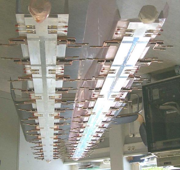
3 2.1 Vacuum Chamber The vacuum chamber is a flat long structure with the base dimensions of 11.5 mm x 128 mm x The central aperture for the beam has a diameter of 9.5-mm. The choice of aluminum as chamber material has the advantage of the low electrical resistance. Aluminum extrusion profiles specifically tailored for this application could be obtained. The previous Advanced Photon Source (APS) experience with the design of aluminum vacuum chambers for insertion devices was widely used [7]. Figure 1 shows the prototype structure of a single chamber period with four electrodes of a beam position monitor (BPM) and the four water cooled steerer windings. The pick up electrodes of the BPM are special UHV compatible RF feed throughs[8] which are connected to the chamber body using special all metal seals[9]. The chamber flange on the right hand is the longitudinal chamber fix point. The connection of the ConFlat flange to the chamber body is formed by a bimetallic welding joint and a flexible junction which allows an elastic bending of the flange for alignment purposes. A more detailed description of the manufacturing and cleaning of the chamber is given in [10]. 2.2 Monitors and Steerers In order to guarantee a tough control of the electron beam orbit inside the undulator one BPM and corrector are required per FODO quadrupol (every 0.478m). All these components have to fit inside the 12mm undulator gap. In total 10 BPM s and 9 correctors are required per undulator chamber. Two kinds of BPM s will be used[11]. For TTF phase I inside the first two chambers button type pick up monitors will be used. These monitors were successfully tested at the CLIC facility at CERN. For the 250µm long bunches which will be available in Phase I these monitors are believed to be a safe and reliable system. For even shorter bunches new solutions have to be found. Therefore in the chamber of the third undulator segment a new type of monitor will be tested which has been described in[12]. It uses outcoupling slits inside the vacuum chamber and waveguides to detect the exact position of the electron beam. These monitors decouple the beam induced RF through four small RF windows. The position information is derived from the four signals. In contrast to the button type monitor this method is not restricted by a lower limit of the bunch length. This new design has a large potential for a use in Phase II when the bunch length will be further reduced to 50µm. The drawback of the waveguide type monitor is its complicated design. It requires complex contours 3
4 to be manufactured inside the undulator chamber. A more sophisticated RF detection electronics allows to define the relative beam position within a few µm. Successful tests of the first prototype at CERN and the second improved design at DESY have proven the capability of this monitor type. Figure 2 and 3 show the waveguide monitor design after machining by an electrical discharge machining (EDM) process. At the end of the U-type waveguide an asymmetric window couples into the beam pipe. The corrector coils are located in between the BPM s. The generation of corrector fields to the electron beam is complicated by the presence of soft iron poles inside the undulator and soft iron girders. So no external coils could be used. Therefore the so called Four Wire Steering principle was chosen. Per corrector there are four single turn coils of 0.3m length.. They are made from a mm hollow copper profile which is insulated against the vacuum chamber. All four wires are grouped symmetrically around the electron beam tube and are inside the undulator gap. These four wire steerers can in principle provide horizontal and vertical steering when properly connected to two power supplies. But it was found sufficient that horizontal steering is applied for the horizontal focusing quadrupoles and vertical steering for the vertical ones. Only the last corrector in each chamber is a double steerer as described above. In this way five horizontal and five vertical steerers are available in each undulator segment. The steering strength of one corrector is about 0.3 Tmm. The hollow copper coils are connected to cooling water which transports off the ohmic heat produced by the current in the corrector coils and RF losses caused by the BPM s. A worst case estimate for the total dissipated power is less than about 30W. A second purpose of the cooling is to thermally stabilize the undulator chamber in order to avoid temperature gradients through the undulator. Therefore the temperature of the cooling water is controlled by precise thermostats. 2.3 Chamber Alignment and Support Structure Special mounting, alignment and supporting systems for the flat and longitudinal very flexible chamber were designed and built. The chamber is flanged directly to the diagnostic block on one side. This defines the longitudinal position of the chamber. In the undulator the chamber is hold by 9 cardanical sliding supports which are connected to the undulator support system. Each support allows to align the chamber within a tenth of a mm in vertical and horizontal direction. The number of supports were defined by finite element model 4
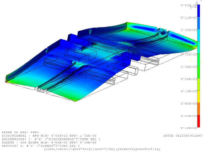
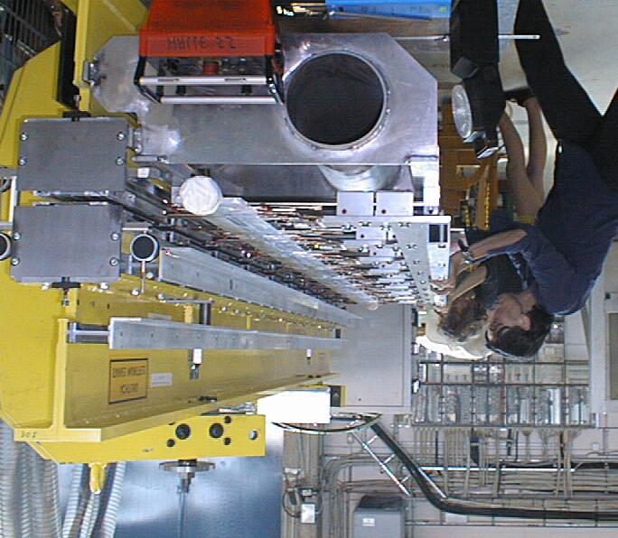
5 calculation. The FEM model suggests that the chamber is hanging like a garland in the chamber supports. The vertical bending of the chamber should not exceed 0.1 mm. Figure 5 shows the calculation for one supporting period which contains a position monitor and a steerer coil. The vertical deviation due to gravity bending is of the order of 6 µm. The mechanical machining tolerances (< 0.1mm) and the fine adjustment of the chamber influence the absolute beam position measurement. The monitors are used for a relative beam position adjustment. Therefore an alignment tolerance of the chamber < 0.3mm is sufficient. 3. Chamber mounting Since the chamber tube must reach a specific outgassing rate < mbar l/sec cm 2, careful cleaning of the chamber is mandatory. To fulfil the stringent particle free requirements of the TTF cleaning, assembling, and mounting of the chamber was made inside a clean room better than class 100. This chamber processing step was done at the APS[10]. A special problem was the insertion of the chamber in the undulator gap. A special 4.5 m long sliding system was built. After alignment the chamber was moved into the undulator gap (see Fig. 6) and then connected to the chamber support. The vacuum chamber together with the undulator module were transferred into the TTF linac tunnel. The vacuum connections to the monitor blocks on both ends of the vacuum chamber were made in a local clean room better class 100. After pumping down of the undulator vacuum system at the undulator ends a pressure < mbar was reached. 4. Conclusion Three FEL vacuum chambers were successfully installed in the undulator section of the TTF linac. The vaccuum system has reached the anticipated pressure, so that the first FEL beam can be produced. 5
6 References [1] J. Roßbach, Nucl. Instrum. and Methods A 375, 269 (1996) [2] J. Feldhaus and B. Sonntag Synchrotr. Rad. News 11, 1, 14 (1998) [3] Yu. M. Nikitina and J. Pflüger, Nucl. Instrum. and Methods A 375, 325 (1996) [4] B. Faatz, J. Pflüger, and Yu. M. Nikitina, Nucl. Instrum. and Methods A 393, 380 (1997) [5] see J. Pflüger, these proceedings [6] D. Edwards, D. Hubert, A. Matheisen, H. P. Wedekind, H. Weise, and K. Zapfe-Düren, Proposed Cleaning Procedures for the Vacuum Components for the TESLA Test Facility, TESLA report 15(1997) [7] P. Den Hartog, E. Trakhtenberg, G. Wiemeslage et al., " Advanced Photon Source Experience with Vacuum Chamber for Insertion Devices", PAC 97, Vancouver, Canada, May [8] KAMAN Instrumentation Corporation, USA [9] VATSEAL, VA T Vakuumventile AG, Schweiz [10] U. Hahn, J. Pflüger, M. Rüter, P. Den Hartog, E. Trakhtenberg, G. Wiemeslage et al., " The Vacuum Chambers for the VUV SASE FEL at the TESLA Test Facility at DESY ", PAC 99, New York, USA, March 29 April2, [11] R. Lorenz, T. Kamps, U. Hahn, and M. Wendt, Beam Position Monitors inside the FEL Undulator at the TTF Linac, PAC 97, Vancouver, Canada, May 1997 [12] T. Kamps, R. Lorenz, et. al Design and Test of a new Beam Position Monitor for the Undulator of the TTF-FEL, Proceedings of the EPAC98, Stockholm, Sweden, 1998 [13] P. Castro, Proceedings of the EPAC98, Stockholm, Sweden,
7 Figure captions Figure 1: Prototype structure of the FEL vacuum chamber with steerers, pick up monitors and end flanges Figure 2: Figure 3 : Cross section of the vacuum chamber at the position of the waveguide BPM. The prototype chamber profile with the waveguide monitor which will be installed in the third chamber Figure 4: Figure 5: Two vacuum chambers ready for installation into the undulator. The FEM calculation shows the vertical displacement of one chamber period between two chamber supports. The vertical bending is smaller than 10 µm. Figure 6: The insertion of the vacuum chamber 7

8 Fig. 1 Fig. 2 8
9 Fig. 3 9
10 Fig. 4 10
11 Fig. 5 11
12 Fig. 6 12
The Gas Attenuator of FLASH
 INTRODUCTION The Gas Attenuator of FLASH K. Tiedtke, N. von Bargen, M. Hesse, U. Jastrow, U. Hahn The experimental hall of the FLASH user facility is located approximately 30m behind the last dipole magnet
Residual Gas Analysis Systems for Industry
 HIDEN RC SYSTEMS QUADRUPOLE MASS SPECTROMETERS FOR RGA, GAS ANALYSIS AND PROCESS MONITORING The HAL RC systems are designed for RGA, gas analysis and process monitoring applications including leak detection,
EXPERIENCE WITH A PRE-SERIES SUPERFLUID HELIUM TEST BENCH FOR LHC MAGNETS
 EUROPEAN ORGANIZATION FOR NUCLEAR RESEARCH European Laboratory for Particle Physics Large Hadron Collider Project LHC Project Report 388 EXPERIENCE WITH A PRE-SERIES SUPERFLUID HELIUM TEST BENCH FOR LHC
LCLS Heavy Met Outgassing Tests * K. I. Kishiyama, D. M. Behne Lawrence Livermore National Laboratory
 UCRL-TR-223160 LCLS-TN-06-12 July 12, 2006 LCLS Heavy Met Outgassing Tests * K. I. Kishiyama, D. M. Behne Lawrence Livermore National Laboratory Abstract A Heavy Met that is 95% tungsten, 3% nickel and
Kicker types for In- and Ejection in the damping Rings of TESLA
 1 4.12.2000 Kicker types for In- and Ejection in the damping Rings of TESLA Jürgen Rümmler DESY / MIN Synopsis 1. Three kicker systems are to see 2. Strip line kicker Fig. 1 2.1 Conception of the kicker
Numerical Tools for LCLS-II Vacuum Systems
 Numerical Tools for LCLS-II Vacuum Systems G. Lanza, D. Gill, SLAC National Accelerator Laboratory AVS, November 2 nd 2017 Doc. N. SLAC-PUB-17166 Work described in this presentation is supported by the
Magnetic Level Gauges
 Bulletin B 03 04 Magnetic Level Gauges Remote Reading Systems Magnetic Level Switches Magnetic level gauges OPERATING PRINCIPLE The operation of the magnetic level gauge is based on some elementary physical
THE PROCESS OF JOINT INTEGRITY
 BOLTED JOINTS A.333 THE PROCESS OF JOINT INTEGRITY To assist in managing a process, ask yourself the following questions: why, what, who, and how? Why do we need a Flange Joint Integrity program? This
Cryogenics of SRF Spoke Cavity Development at SMTF
 Cryogenics of SRF Spoke Cavity Development at SMTF Michael White SRF Development Technical Division Fermi National Accelerator Laboratory May 11, 2006 Overview of Topics SMTF Overview CTF Cryogen Supply
Requirements For The Construction Of The LCLS Magnetic Measurements Laboratory
 LCLS-TN-04-1 Requirements For The Construction Of The LCLS Magnetic Measurements Laboratory Zachary Wolf, Robert Ruland SLAC February 9, 2004 Abstract A magnetic measurements laboratory will be built at
Proposal for the Cryogenic Supply of a Single TTF / FEL - Cryomodule Test Bench
 Proposal for the Cryogenic Supply of a Single TTF / FEL - Cryomodule Test Bench TESLA Report No. 2001-09 W.D.Moeller, B.Petersen, B.Sparr Deutsches Elektronen Synchrotron Abstract A test bench for the
TIGHTNESS. Glass sealing Thanks to our glass-sealing technology, ODU products can meet the most demanding tightness requirements.
 TIGHTNESS Glass sealing Thanks to our glass-sealing technology, ODU products can meet the most demanding tightness requirements. ODU has the necessary expertise for developing and manufacturing connectors
better measurement Simply a question of SCHMIDT Flow Sensor SS The cost-effective alternative in pressurised systems up to 10 bars.
 Simply a question of better measurement SCHMIDT Flow Sensor SS 20.261 The cost-effective alternative in pressurised systems up to 10 bars. Compressed air technology Industrial processes A cost analysis
Current Leads for Cryogenic Systems
 Current Leads for Cryogenic Systems American Magnetics Inc. s (AMI) Vapor Cooled Current Leads provide reliable and consistent electrical current transfer from room temperature (300K) to a Liquid Helium
DEVICES FOR FIELD DETERMINATION OF WATER VAPOR IN NATURAL GAS Betsy Murphy MNM Enterprises 801 N. Riverside Drive Fort Worth, Texas 76111
 INTRODUCTION Water vapor in natural gas has more than a substantial effect on the quality of the gas stream. Without quality measurement of water vapor the gas is basically not saleable. Contracts are
Weld seams without temperature discoloration every time!
 Weld seams without temperature discoloration every time! Patent Numbers: DK198389, US 4956537, US 5126526, US 5217156, CA 1322229, Aust 617189, HK1005926, EP 348125, 328131, EP 486420, 592055, 1005927,
Revisions to the Regulations for Agility Trials
 Revisions to the Regulations for Agility Trials Effective January 2, 2018 Equipment changes may be done prior to January 2, 2018, but must be completed by January 2, 2018 This insert is issued as a supplement
Assembly and measurements of a mechanical prototype of the BIS MDT chamber
 ATLAS Internal Note MUON NO 243 9 June 1998 Assembly and measurements of a mechanical prototype of the BIS MDT chamber K. Ekonomou Physics Department, Aristotle University of Thessaloniki, Thessaloniki,
How to specify a product. Process Sensors and Mechanical Instruments
 How to specify a product Process Sensors and Mechanical Instruments Keep the overview. Here is some guideline information on how to specify our products. Intended as supplementary help to specification
ATLAS RPC QA results at INFN Lecce
 ATLAS RPC QA results at INFN Lecce M. Bianco,, I. Borjanovic, G. Cataldi, A. Cazzato,, G. Chiodini, M.R. Coluccia,, P. Creti, E. Gorini,, F. Grancagnolo, R. Perrino, M. Primavera, S. Spagnolo,, G. Tassielli,,
Info Counting chamber (haemacytometer)
") Info Counting chamber (haemacytometer) 1. What is a counting chamber and what is it used for? A counting chamber is a precision measuring instrument made of special optical glass. It is used to count cells
Info Counting chamber (haemacytometer) 1. What is a counting chamber and what is it used for? A counting chamber is a precision measuring instrument made of special optical glass. It is used to count cells
CVI Valve Line. Exceeds the industry s highest standards for reliability and performance
 CVI Valve Line Exceeds the industry s highest standards for reliability and performance Available in the most standard models with the shortest lead times in the industry Exceptional quality every CVI
Structural Design of Tank Weighing Systems
 Structural Design of Tank Weighing Systems 1. Initial observations Some essential rules must be followed when installing load cells in tanks. For example, tanks are frequently subject to weather conditions
Barcol-Air BRM Radiant Module
 Barcol-Air BRM Radiant Module General The high capacity Radiant Cooling Module BRM is based on the principles of the radiant cooling technology. Due to the purpose designed profile and the geometry of
Deformation Measurements at the Vehicle Tunnel Overpass using a Hydrostatic Level System
 Deformation Measurements at the Vehicle Tunnel Overpass using a Hydrostatic Level System Advanced Photon Source H. Friedsam, J. Penicka, J. Error - April 1996 1. Introduction Long-term storage ring and
Design of a Solid Wall Transonic Wind Tunnel
 Design of a Solid Wall Transonic Wind Tunnel David Wall * Auburn University, Auburn, Alabama, 36849 A solid wall transonic wind tunnel was designed with optical access from three sides to allow for flow
Fig. 1: Mechanical vacuum gauge (left) and capacitive vacuum gauge (right)
 and capacitive vacuum gauge (right)") Dear Readers! This is your 4pvd Newsletter. We hope you enjoy the information it contains. If you wish to unsubscribe, please send a blank Email to unsubscribe@4pvd.de June 1 st, 2006, Issue No. 24 Principles
Dear Readers! This is your 4pvd Newsletter. We hope you enjoy the information it contains. If you wish to unsubscribe, please send a blank Email to unsubscribe@4pvd.de June 1 st, 2006, Issue No. 24 Principles
Corrugated Hose Loop Calculations
 Corrugated Hose Loop Calculations The loop installation is one of the most common application for metal hoses. It allows the flexible hose assembly to work properly. Care must always be exercised to ensure
CHANGE RECORDS TABLE OF CONTENTS
 CHANGE RECORDS Ed./Rev. Date Verified and approved by Description Writer 1 12/31/2015 WY / LLR Initial Document FS 2 02/26/2016 FS / LLR - 1.2. : new applicable document added : validation of the mounting
ROFIN DC SERIES. Diffusion-Cooled CO 2 Lasers Cutting and Welding without a Break.
 THE POWER OF LIGHT LASER MACRO ROFIN DC SERIES Diffusion-Cooled CO 2 Lasers Cutting and Welding without a Break. ROFIN DC SERIES THE PRODUCT Highest Reliability Lowest Maintenance Effort Cutting, welding
Single and Canted Undulator Front-Ends
 Single and Canted Undulator Front-Ends 3470 Mainway, Burlington JUV Front End - Installation stage photo (ID11-1/ Duplex FE at CLS) Johnsen Ultravac Front Ends Technical Specifications Page 1 of 7 FRONT
Development Of The Compressor For Miniature Pulse Tube Cryocooler
 Purdue University Purdue e-pubs International Compressor Engineering Conference School of Mechanical Engineering 2002 Development Of The Compressor For Miniature Pulse Tube Cryocooler K. Toyama Y. Yasukawa
STRUCTURAL ANALYSIS OF THE VACUUM VESSEL FOR THE LHCb VERTEX LOCATOR (VELO)
") National Institute for Nuclear Physics and High Energy Physics Kruislaan 409 1098 SJ Amsterdam The Netherlands NIKHEF Reference no.: MT-VELO 04-1 EDMS no: 432626 OF THE VACUUM VESSEL FOR THE LHCb VERTEX
National Institute for Nuclear Physics and High Energy Physics Kruislaan 409 1098 SJ Amsterdam The Netherlands NIKHEF Reference no.: MT-VELO 04-1 EDMS no: 432626 OF THE VACUUM VESSEL FOR THE LHCb VERTEX
Engineering and Design Rules for Hopper Scales
 Engineering and Design Rules for Hopper Scales Defining hopper scale Dimensioning hopper scale Selecting load cell mounts Ambient influences and shunt forces Hopper scale accuracy we make processes work
The Transition Radiation Detector of the AMS-02 Experiment
 The Transition Radiation Detector of the AMS-02 Experiment Simonetta Gentile Università di Roma La Sapienza, INFN (Italy) for: RWTH Aachen, MIT, KNU Daegu, IEKP Karlsruhe, Universita La Sapienza, & INFN
FPG8601 Force Balanced Piston Gauge
 FPG8601 Force Balanced Piston Gauge Reference Level Calibration System for very low pressure Pressure range: 0 to 15 kpa gauge, absolute and absolute differential Standard resolution: 0.010 Pa, high resolution
Granville-Phillips Series 370 Stabil-Ion Vacuum Gauge Controller
 Granville-Phillips Series 370 Stabil-Ion Vacuum Gauge Controller All-metal, rack-mount controller for Stabil-Ion and Convectron vacuum gauges is noise-immune and CE compliant Accurate vacuum pressure measurement
ASME Boiler & Pressure Vessel Code Analysis of the 1497 MHz High-Current Cryomodule Helium Vessel
 1.0 Introduction ASME Boiler & Pressure Vessel Code Analysis of the 1497 MHz High-Current Cryomodule Helium Vessel Katherine Wilson 28 May 2007 To minimize the hazards associated with vacuum and pressure
ESAIL D3.1.1 Requirement specifications of the tether test reels
 D3.1.1 Requirement specifications of the tether test reels Work Package: WP 3.1 Version: Version 1.0 Prepared by: DLR German Aerospace Center, Olaf Krömer, Roland Rosta Time: Bremen, May 30 th, 2011 Coordinating
Calculation tables for thermal expansion.
 Calculation tables for thermal expansion www.sanha.com 2 Contents Subject Page 1 THERMALLY INDUCED CHANGES IN LENGTH 5 1.1 Thermal expansion 6 1.1.1 NiroSan -, NiroSan -ECO system pipes and copper pipes
A Reliable and Tracer Gas Independent Leak Detector for Food Packages
 19 th World Conference on Non-Destructive Testing 2016 A Reliable and Tracer Gas Independent Leak Detector for Food Packages Silvio DECKER 1 1 INFICON GmbH, Köln, Germany Contact e-mail: Silvio.Decker@inficon.com-
Variable Temperature Storage Dewar Mount Inserts
 Variable Temperature Storage Dewar Mount Inserts All inserts are available for either Liquid Helium or Liquid Nitrogen Dewars! DStat - External cryostat with insert leg DStatMag - Super Conducting Magnet
Magnetic level switch type MR783 Instruction Manual
 Magnetic level switch Magnetic level switch type MR783 1. DESCRIPTION page 3 1.1 Operation page 3 1.2 Application page 3 1.3 Description page 3 2. SPECIFICATIONS page 3 2.1 Service Conditions page 4 2.2
SPECIFICATION FOR AN MRBR 9.4 TESLA/310MM/AS CRYO-COOLED MAGNET SYSTEM
 SPECIFICATION FOR AN MRBR 9.4 TESLA/310MM/AS CRYO-COOLED MAGNET SYSTEM Prepared by:- Magnex Scientific Limited The Magnet Technology Centre 6 Mead Road Oxford Industrial Park Yarnton, Oxford OX5 1QU, UK
RC102 & RC110 Sample in Vacuum Continuous Flow Cryogenic Workstation Cryostats
 RC102 & RC110 Sample in Vacuum Continuous Flow Cryogenic Workstation Cryostats www.cryoindustries.com INDUSTRIES RC102 & RC110 Sample in Vacuum Continuous Flow Cryogenic Workstation Cryostats Designed
SHMS. Downstream Beamline. Large SHMS/HMS Angles (Config-1) Large SHMS / Min HMS Angle (Config-2) Dan Young Ext /26/2015 1
 Large SHMS / Min HMS Angle (Config-2) Dan Young Ext /26/2015 1") SHMS Dan Young Ext 5255 Downstream Beamline Large SHMS/HMS Angles (Config-1) Large SHMS / Min HMS Angle (Config-2) 1/26/2015 1 10 14.5 SHMS Beam Line Large SHMS/HMS Angles (Configuration-1) SHMS minimum
SHMS Dan Young Ext 5255 Downstream Beamline Large SHMS/HMS Angles (Config-1) Large SHMS / Min HMS Angle (Config-2) 1/26/2015 1 10 14.5 SHMS Beam Line Large SHMS/HMS Angles (Configuration-1) SHMS minimum
Check with local zoning official for property line distance requirements.
 RESIDENTIAL POOL PLAN SUBMITTAL GUIDELINES The following guidelines are intended to assist municipal residents with the permit acquisition process with regard to pools, spas and hot tubs for single family
Magnet and RF Cavity Test Stand Design. Tom Peterson, SLAC USPAS January, 2017
 Magnet and RF Cavity Test Stand Design, SLAC Outline Test dewars and test stands Saturated bath test dewars Double bath test dewars SRF test cryostats SRF cryomodule test stands Horizontal magnet test
A hose layline contains important information for specifying the replacement assembly: manufacturer, hose trade name, working pressure and hose ID.
 CONTENTS Introduction Pressure Pressure Drop Temperature Rating Bend Radius Conclusion Additional Information SIDEBAR: Understanding Hydraulic Hose Reinforcement INTRODUCTION Hydraulic hose has a finite
2.8 Beam Stops Introduction. 2.8 Beam Stops
 2.8 Beam Stops 2.8 Beam Stops 2.8.1 Introduction Three very different beam stops are required for the ERL. These are the primary beam stop, tune-up stops, and moderate power stops for high-energy beams.
DR.ING. CARLO AVANZINI PROFESSIONAL ENGINEER GRIP TEST REPORT NOVA SIRIA, ROLETTO, Premise
 GRIP TEST REPORT NOVA SIRIA, ROLETTO, 07.10.2013 1. Premise The present report covers the witnessing of the test conducted in the Nova Siria Factory in Roletto (Torino, Italy) to verify the behavior of
Instruction Manual Contact Pressure Vacuum Gauge
 MS10 Instruction Manual Contact Pressure Vacuum Gauge Table of Contents 1. Safety Instructions 2. Intended Applications 3. Product Description and Functions 4. Installation 5. Commissioning 6. Maintenance
Pressure & Vacuum Measurement. Series 370. Solutions. Stabil-Ion Vacuum gauge and Controller
 w w w. m k s i n s t. c o m Pressure & Vacuum Measurement Solutions Series 370 Stabil-Ion Vacuum gauge and Controller Features & Benefits All-metal, rack-mount controller for Stabil-Ion and Convectron
deltaflowc deltaflowc Venturi or Probe
 deltaflowc Mass Flowmeter for Gases - Multivariable with ultra fast dp, p and T-sensors - Compact, accurate and user-friendly - Ideal for OEMs deltaflowc Venturi or Probe Precise mass flow metering deltaflowc
Acoustic Emission Testing of The Shell 0f Electromagnetic Valve
 17th World Conference on Nondestructive Testing, 25-28 Oct 2008, Shanghai, China Acoustic Emission Testing of The Shell 0f Electromagnetic Valve guozhen XU 1, yiwei CHEN 1, zhihua CAO 2 ABSTRACT Shanghai
Differential pressure
 Differential pressure 9 Overview Page 200 VEGADIF 65 Page 202 Chemical seal Page 204 Accessory Page 208 199 VEGADIF For differential pressure, level and flow measurements Measuring principle The sensor
Victoreen B. Operators Manual. Image Intensifier Ion Chamber
 Victoreen 6000-530B Image Intensifier Ion Chamber Operators Manual March 2005 Manual No 6000-530B-1 Rev. 4 2004, 2005 Fluke Corporation, All rights reserved. All product names are trademarks of their respective
VACGEN. Vacuum Components. Product Overview
 VACGEN Product Overview WHY CHOOSE US? In 1964 the Vacuum Generators company was formed in East Grinstead, UK, by Dr Bernard Eastwell and Vic Treasure with a single product - the CR38 all metal right angled
TEST PROTOCOL VERIFICATION OF THE BEHAVIOUR OF A MECHANICAL COMPRESSION COUPLING DURING SETTLEMENT
 TEST PROTOCOL VERIFICATION OF THE BEHAVIOUR OF A MECHANICAL COMPRESSION COUPLING DURING SETTLEMENT Nova Siria factory, Roletto, April 6, 2011 Introduction Mechanical steel compression couplings (CC) are
Analysis of dilatometer test in calibration chamber
 Analysis of dilatometer test in calibration chamber Lech Bałachowski Gdańsk University of Technology, Poland Keywords: calibration chamber, DMT, quartz sand, FEM ABSTRACT: Because DMT in calibration test
Succeeding with Production Air Leak Testing Methods. Paul Chamberlain President, CEO
 Succeeding with Production Air Leak Testing Methods Paul Chamberlain President, CEO 2 Overview Air Leak Testing Overview Pressure Decay Air Leak Testing Factors impacting leak rate measurement Test Data:
LFE OEM TCD - Thermal Conductivity Detector
 LFE OEM TCD - Thermal Conductivity Detector Key features Quick response - T90 3 sec Extremely suppressed ranges High corrosion resistance High temperature capability up to 180 C Infallible containment
3200 Dwight Road Suite #100 Elk Grove, CA Ph: Fax: GNB Corporation
 3200 Dwight Road Suite #100 Elk Grove, CA 95758 Ph: 916-395-3003 Fax: 916-395-3363 www.gnbvalves.com info@gnbvalves.com GNB Corporation Vacuum Excellence Defined A Message from our President Welcome, and
Oil-Lubricated Compressors for Regenerative Cryocoolers Using an Elastic Membrane
 Oil-Lubricated Compressors for Regenerative Cryocoolers Using an Elastic Membrane E.C. Luo, Z.H. Wu, G.Y. Yu, J.Y. Hu, and W. Dai Technical Institute of Physics and Chemistry Chinese Academy of Sciences
Precision Liquid Settlement Array Manual
 Precision Liquid Settlement Array Manual All efforts have been made to ensure the accuracy and completeness of the information contained in this document. RST Instruments Ltd reserves the right to change
ACCURACY, PERFORMANCE, AND HANDLING OF OIL-FILLED DIGIQUARTZ PRESSURE INSTRUMENTATION
 Application Note Doc. G8108-001 Rev. A - 23-Jul-02 ACCURACY, PERFORMANCE, AND HANDLING OF OIL-FILLED DIGIQUARTZ PRESSURE INSTRUMENTATION For more information regarding Digiquartz products contact: Paroscientific,
Polarimeter tubes and accessories
 Polarimeter tubes and accessories Opto-electronic measuring device since 1864 Polarimeter tubes of SCHMIDT+HAENSCH are designed for different applications. All tubes meet the ICUMSArecommendations, class
Design and Construction of a GEM-TPC Prototype for R&D Purposes
 Design and Construction of a GEM-TPC Prototype for R&D Purposes 2003 IEEE NSS - Satellite Workshop on Micro-Pattern Detectors for Time Projection Chambers Portland, Oregon (USA) 19-25 October, 2003 1)
Low Wind High Yields Series
 Low Wind High Yields Series Wind Turbines USER S MANUAL Introduction Low Wind High Yields Series rotor blades apply the latest advanced thermoplastic engineering and are manufactured by precision injection
Vibration Analysis and Test of Backup Roll in Temper Mill
 Sensors & Transducers 2013 by IFSA http://www.sensorsportal.com Vibration Analysis and Test of Backup Roll in Temper Mill Yuanmin Xie College of Machinery and Automation, Wuhan University of Science and
Level MEASUREMENT 1/2016
 Level MEASUREMENT 1/2016 AGENDA 2 A. Introduction B. Float method C. Displacer method D. Hydrostatic pressure method E. Capacitance method G. Ultrasonic method H. Radar method I. Laser method J. Level
Development of Cleaning and Processing Techniques for UHV/XHV at Daresbury Laboratory Keith Middleman
 Development of Cleaning and Processing Techniques for UHV/XHV at Daresbury Laboratory Keith Middleman ASTeC Vacuum Science Group STFC Daresbury Laboratory Accelerators + Vacuum Particle accelerators come
Training for Proofmaster M/S/Automat. Functional principle for airtightness testing
 Training for Proofmaster M/S/Automat Functional principle for airtightness testing July 2017 Airtightness measurement 1. Measuring principle 2. Behaviour of the watch under vacuum 3. Behaviour of the watch
Characteristics and Production of Gas Sealed, Radiation Hard, Small Ionization Chambers
 Characteristics and Production of Gas Sealed, Radiation Hard, Small Ionization Chambers Mayda Velasco 1 Gianni Tassotto 3 on behalf of the SIC team P. Ball 2, A.Dabrowsky 1, G. Graham 2, C. Kendziora 3,
tubepress press procedure
 tubepress press procedure tubepress 15mm up to 35mm tubepress 15 mm up to 35 mm 1. The tube ends must be clean with no scratches or grooves. Remove end caps. Cut tube to length. 2. Deburr tube inside and
Lecture 10 : Sewer Appurtenances
 1 P age Module 8 : Sewer Appurtenances Lecture 10 : Sewer Appurtenances 2 P age The structures, which are constructed at suitable intervals along the sewerage system to help its efficient operation and
Slide 1 / What is the density of an aluminum block with a mass of 4050 kg and volume of 1.5 m 3?
 Slide 1 / 68 1 What is the density of an aluminum block with a mass of 4050 kg and volume of 1.5 m 3? Slide 2 / 68 2 What is the mass of a rectangular shaped ice block with dimensions of 0.04m x 0.05m
OPENINGS AND REINFORCEMENTS 26
 ASME BPVC.VIII.1-2015 UG-35.2 UG-36 (4) It is recognized that it is impractical to write requirements to cover the multiplicity of devices used for quick access, or to prevent negligent operation or the
1.0 - OPENING AND CLOSING THE DOOR
 The purpose of this manual is to provide the user with instructions on how to safely open and close, how to conduct routine maintenance, and how to install the PEI TWINLOCK Closure on a pressure vessel.
Y692VB Series Vacuum Breaker
 Y692VB Series Vacuum Breaker Bulletin 71.3:Y692VB June 2009 W7429 Figure 1. Type Y692VB Vacuum Breaker Introduction The Y692VB Series direct-operated vacuum breakers are used for the precise control of
Roughneck TM Mesh Slings
 Roughneck TM Slings ROUGHNECK WIRE MESH SLINGS Widely used in metalworking shops and steel warehouses where loads are abrasive, hot or tend to cut web slings Features and Benefits Promotes Safety Steel
Customer Responsibilities
 Thank you for purchasing an Agilent instrument. To get you started and to assure a successful and timely installation, please refer to this specification or set of requirements. Correct site preparation
Yoke Instrumentation: ILD Muon System / Tail Catcher. Valeri Saveliev IAM, RAS, Russia DESY, Germany 3 June, 2016
 Yoke Instrumentation: ILD Muon System / Tail Catcher Valeri Saveliev IAM, RAS, Russia DESY, Germany 3 June, 2016 ILD Muon System/Tail Catcher µ - µ + Events/0.2 [GeV] 150 + Zh µ µ - X 100 50 s = 250 GeV
Development of Low Volume Shape Memory Alloy Variable Ballast System for AUV Use
 Development of Low Volume Shape Memory Alloy Variable Ballast System for AUV Use Dr. Graeme J Rae Ocean Engineering Program Division of Marine and Environmental Systems Florida Institute of Technology
CHAIN LINK FENCE GATE
 WALCOOM Walcoom Corporation CHAIN LINK FENCE GATE Chain link fence gate is a versatile product in many aspects, here, Walcoom provides buyers with sufficient strength and durability chain link fence gate
SABERINDO PACIF SABERINDO PACIFIC CIFIC SABERINDO PA. A Tyco International Company
 CIF A Tyco International Company 1 Foam Concentrate CIF 3% AFFF -UL Listed -UL Canada Listed 6% AFFF 6 parts AFFF concentrate to 94 parts water -UL Listed- Foam Liquid -UL Canada Listed 3% FLUOROPROTEIN
Technical Note. Determining the surface tension of liquids by measurements on pendant drops
 Technical Note Pendant Drop Measurements Technical note: TN316e Industry section: all Author: FT, TW Date: 12/2010 Method: Drop Shape Analyzer DSA100 Keywords: Methods, surface tension, interfacial tension,
Vacuum Insulation Panels for Buildings and Technical Applications
 Vacuum Insulation Panels for Buildings and Technical Applications Roland Caps va-q-tec AG, Karl-Ferdinand-Braun-Str. 7, D-97080 Würzburg, www.va-q-tec.com ABSTRACT Vacuum insulation panels, which may be
World Area Differences Technical Information
 World Area Differences Technical Information DMISC2047X02 This document is to give more information about the following: Porting & Threads Cleaning Procedures Conversion Tables PORTING & THREADS NPT (National
Size : Connection Ends : Min Temperature : Max Temperature : Materials : Cast iron body
 Size : Connection Ends : Min Temperature : Max Temperature : DN 50 to 200 Flanged ISO PN 10/16 ( ISO PN16 for DN200 ) 0 C + 50 C Max Pressure : 16 Bars Specifications : Tangential type Dry dial Magnetic
First Measurements with the Gas Cell for SHIPTRAP
 Hyperfine Interactions 132: 505 509, 2001. 2001 Kluwer Academic Publishers. Printed in the Netherlands. 505 First Measurements with the Gas Cell for SHIPTRAP O. ENGELS 1,L.BECK 1, G. BOLLEN 2, D. HABS
UHP - UHV APPLICATIONS
 UHP - UHV APPLICATIONS High Performance Seals and Sealing Systems FOREWARD Today s sealing requirements for Ultra-High Purity and Ultra-High Vacuum are more demanding than ever before: Ultra-low Leak Rates
Unit 1, Fullerton Road Rotherham S60 1DJ. Tele: Fax:
 Unit 1, Fullerton Road Rotherham S60 1DJ Tele: 0845 601 333 6 Fax: 0845 601 333 7 info@fabricatedproducts.co.uk www.fabricatedproducts.co.uk Data Sheet 6.0 Rubber Pump Flexes All rubber bellows are suitable
Tightening Evaluation of New 400A Size Metal Gasket
 Proceedings of the 8th International Conference on Innovation & Management 307 Tightening Evaluation of New 400A Size Metal Gasket Moch. Agus Choiron 1, Shigeyuki Haruyama 2, Ken Kaminishi 3 1 Doctoral
Flow in a shock tube
 Flow in a shock tube April 30, 05 Summary In the lab the shock Mach number as well as the Mach number downstream the moving shock are determined for different pressure ratios between the high and low pressure
DESIGN AND PERFORMANCE OF THE NEW SARTORIUS 1 KG VACUUM MASS COMPARATOR AT PTB
 XVIII IMEKO ORLD CONGRESS Metrology for a Sustainable Development September, 17 22, 2006, Rio de Janeiro, Brazil DESIGN AND PERFORMANCE OF THE NE SARTORIUS 1 KG VACUUM MASS COMPARATOR AT PTB M. Borys 1,
Membrane modules for nitrogen and oxygen generator systems. Technology Overview ENGINEERING YOUR SUCCESS.
 Membrane modules for nitrogen and oxygen generator systems Technology Overview ENGINEERING YOUR SUCCESS. Parker modules the heart of OEM tailor-made nitrogen generators OEM (Original Equipment Manufacturer)
MODEL WEIGH MODULE
 MODEL 65082 WEIGH MODULE INSTALLATION & OPERATING MANUAL P.O. Box 775 - Farmington, NH 03835 Tel: 603-755-3885 email: cands_nh@msn.com www.candscontrols.com Model 65023 Cantilever Beam Transducer Nickel-Plated
SICK AG WHITE PAPER MINIMUM DETECTION TIME FOR SAFETY LASER SCANNERS IN VERTICAL APPLICATIONS
 SICK AG WHITE PAPER MINIMUM DETECTION TIME FOR SAFETY LASER SCANNERS IN VERTICAL APPLICATIONS 2018-02 AUTHORS Otto Görnemann Manager Machine Safety & Regulations at SICK AG in Waldkirch, Germany CONTENT
Rapidmain Installation Guide
 Rapidmain Installation Guide Aluminium Compressed Air Pipe Work Installation Guide Trafalgar Court, Waterloo Ind Estate, Widnes Cheshire. UK. Ref: Rapidmain installation guide 4b Index 1. Rapidmain fittings: