EnCal 3000 Gas Chromatograph Commissioning and Maintenance Manual Biogas and THT-Devices
|
|
|
- Justina Harrell
- 5 years ago
- Views:
Transcription
1 EnCal 3000 Gas Chromatograph Commissioning and Maintenance Manual Biogas and THT-Devices 1/38
2 Document history Version Date Author Changes a Gas Quality Initial version Only operating instructions published by Honeywell are to be used. Changes or translations of these Operating Instructions require the written consent of Honeywell. All obligations of Honeywell arise solely from the agreement concluded and the applicable General Terms and Conditions upon conclusion of the agreement. Warranty conditions Our current warranty conditions as in the General Terms and Conditions are published on our website: Contact Elster GmbH (Manufacturer) Steinern Str Mainz-Kastel / Germany Phone: Customerfirst@Honeywell.com Website: Technical Assistance Center (TAC): Phone: ElsterSupport@Honeywell.com Website: 2/38
3 Kontaktinformationen / Contact Information... Fehler! Textmarke nicht definiert. 1 Introduction Steps for Commissioning Gas Connections and Set Values for the pressure of the connected gases Power Supply and Communication Device Start-Up Check of the parameter settings Preparation of a new Basic Calibration Performance Test Check Lists Visual Inspection Analyzer Equipment Check filters and probes Set up ENCAL Check Method Table Encal 3000 According ISO 6976, GPA or GOST Calibration Encal Accuracy Check Encal Parameter set backup Maintenance Pressure Check and Visual Check of the Equipment New Calibration and Performance Test Checklists first maintenance Checklists second maintenance Checklists third maintenance Checklists fourth maintenance Checklists fifth maintenance /38
4 1 Introduction The first part of this manual describes the main steps of a commissioning for an Encal3000 gas chromatograph. This covers the gas connections and the setting of the pressure for the connected gases, the connection of power supply and communication cables, the start-up of the device, a check of the parameter settings, the preparation of a new basic calibration and a performance test of the device. The second part is focused on the actions that should be done for maintenance. These are a check of the pressures for carrier gas, sample gas and calibration gas, an exchange of internal moisture filters (only for biogas devices), a performance test and an optionally new basic calibration if the calibration gas bottle has to be changed. An advised time period for the maintenance is at least once a year. The commissioning and maintenance should be done only by service people that are qualified for it. To get this qualification Elster offers Encal3000 service and commissioning trainings. 2 Steps for Commissioning This chapter contains a summary of the main steps for the installation of the device in the field. In addition to that it contains a checklist for the installed hardware, the set pressures for the used gases and the used parameter settings for the analysis of the sample gases and for the communication of the results. 2.1 Gas Connections and Set Values for the pressure of the connected gases The following gases are needed for the operational work of the device: - carrier gas: Helium with a quality of 5.0 or higher Supply pressure 5.5 barg Flow ± 4 ml/min per channel - calibration gas: Composition preferably close to pipe line composition Quality 2.0 or higher (with a maximal uncertainty of 1% relative deviation for each component) Supply pressure 1 to 4 barg nominal; Pressure peak protection up to 4 barg; Flow ± 30 ml/min - up to five different sample gases, in the most application one or two different sample gases has to be analysed For each of these gases stainless steel tubes should be used for the piping. The connection to the device is done with 1/8 Swagelok connections. It is possible to use another size for the tubes but than adapters to 1/8 are needed. Before these tubes become connected to the device they should be flushed for about 30 seconds with the carrier gas to remove particles, rest air and rest moisture that is inside these tubes. For the sample gas tubes it is also possible to flush it with sample gas if the sample gas pressure has been reduced already to 1-4 barg. Advised is to close the gas supply from the pipeline and to use only the rest pressure in the tubes for the flushing with sample gas. This should be done to limit the amount of flameable gas that would come out of the tubes during this flushing. A carrier gas cylinder has typically volume of 50l at a pressure about 200 barg. For the regulation of the pressure that is needed for the carrier gas supply of the device a pressure reduction, that reduces the pressure to a range of 5-6 barg, is needed. The optimal set pressure for the carrier gas supply of the device is 5.5 barg. Preferred is to use a dual stage regulator for the carrier gas. 4/38


5 The device cannot operate without carrier gas, because of that it is recommended to have always two carrier gases cylinders available with an easy switch system from one cylinder to the other. In this way it is possible to use the other cylinder if one is already empty and to continue with the sample gas analysation also if the new ordered cylinder has not arrived yet. The change to the second bottle should be done if the fill pressure of the first is below 20 barg. The carrier gas consumption of the Encal3000 is 8 ml/min. One 50l cylinder with an original fill pressure of 200 barg is useable for about two years if it becomes used for one Encal3000. Sometimes there are two or more devices in one station and one carrier gas installation becomes used for all this devices. In this case one 50l cylinder would be useable for a time that is equal to two years divided by the number of devices. The following picture shows an example for a possible installation of carrier gas, calibration gas and the analyzer in one system. An installation like this can be easily used if the device is installed as indoor installation. If the station is build outside without the use of a closed room this installation can also be used but in addition a roof is needed to protect the device from direct sunlight, from rain etc. Advised is to put this installation in a cabinet to be able to guarantee stable measurement conditions. 5/38

6 For the calibration gas it is possible to use a 10l cylinder because the consumption of the calibration gas is very low. Typically one 10l cylinder with an original fill pressure of 120 barg is useable for more than three years and after this time the certificate would also be not valid anymore. The use of a calibration gas which is close to the sample gas is only advised if only one sample gas becomes analysed and if the variation of this sample gas is not strong. Also important is that the concentration of the components in the calibration gas are not too small, they should be at least ten times higher than the detection limit, otherwise the calculated response factors can be too unstable. In the following table the composition for a typical calibration gas useable for biogas and THT-Analysers is described. Component name Calibration Gas [mol%] Measurement range [mol%] Nitrogen (N2) Methane (CH4) balance Carbon Dioxide (CO2) Oxygen (O2) THT Hydrogen Sulphide (H2S) Carbonyl Sulphide (COS) The allowed pressure range for the calibration gas and the sample gases after the pressure reduction is 1-4 barg, advised is to use a set pressure of about 2 barg for these gases. 6/38
 is needed (see hardware manual chapter 5.1.6), the third position for the ground should not be used.")
7 2.2 Power Supply and Communication The next step is to prepare the connections for power supply, Modbus communication and TCPcommunication. For the power supply a two wire connection (+ and -) is needed (see hardware manual chapter 5.1.6), the third position for the ground should not be used. For the grounding of the device use the prepared connection at the bottom of the housing instead. The required voltage for the device is 24V. The typical required current for start-up is about 3A for the nonheated version and about 7A for the heated version. It is recommended to use shielded cables for the power supply and for the communication. In addition to that it is recommended to use one entrance in form of the cable glands for the power supply and another for the communication cables. Before the device becomes switched on the above mentioned values for the power should be checked. If the power is too low the device cannot start up and a sound that is comparable to humming noise would come from the Interconnection board of the device. For the TCP-IP communication a four wire cable with the connection of TX+, TX-, RX+ and RX- is needed. The TCP-IP connectors are located near the main board at position J7 of the interconnection board. For Ethernet and serial Modbus communication twisted pair cables should be used. The length of a cable for Ethernet communication is typically limited to 100 meter. For the serial Modbus communication up to two connections with a four wire connection (one pair becomes used for A and B, the remaining two for the ground) are available. The connectors are also located close to the main board at position J6 of the interconnection board (see hardware manual, chapter 5.1.6). Please make sure that all cable glands are sealed when the installation is completed. 7/38
8 2.3 Device Start-Up After the installation is finished the device can be switched on and prepared for the operational work. The first step is to install the RGC3000 software on the computer that becomes used for the communication to the device. The second step is to get communication to the device and to make a backup of the configuration and the parameter Settings of the device. The RGC3000 software can only communicate by TCP-IP to the device. For this communication the I.P. address of the device and the computer must be in the same subnet. For that the Subnet Mask must be the same. For the I.P. address the first numbers must be the same if in the Subnet Mask the number 255 is used. The last numbers of the I.P.-address (other value than 255 for the subnet mask) of the computer, the chromatograph and all other partners in the subnet must be different. Otherwise this results into I.P. conflicts. After deliverance the device has a typical I.P. setting that was used during the production. It is either possible to use this setting or to set a new I.P. address and subnet mask. The original I.P. address is typically labelled at the device (for example ) and the used Subnet Mask is If you like to change the I.P. address to and the subnet mask, don t forget that the change of the I.P. address for a device with old mainboard type is only possible if the device in Boot P mode (see software manual chapter 2.2). For devices with new mainboard type the change of the I.P. address is also possible via a web browser (see also software manual chapter 2.2). The next step is to make an Upload of the configuration and to check if the settings in this configuration are ok. With the command Upload the configuration from the device are loaded into the program. With the command Download the setting becomes sent to the device. After successful Upload the Encal3000 Instrument serial number will present. 8/38

9 In the menu Hardware for the standard device two channels with a heated injector and the available licences should be visible. 9/38

10 In the menu User the used carrier gases for both channels are visible. Here it is important that the right carrier gas type is selected for both channels. For a standard device the right setting is helium for both channels. In addition to that the check button for continues flow should be activated and all available licenses should be activated. For the number of flush cycles the setting is typically None. 10/38

11 In the menu PROstation the type names of the used channel and the unit for the column pressure are visible. This information can be used for example for a check if the right channels are used for an approved operational Analysis. Also if spare parts are needed this information can be used to order the right spare channel type. 11/38

12 In the menu Automation are visible the number of available streams, Relays, In- and Outputs, the used comports for Modbus communication and the corresponding baud rate. Check here if these settings for the Modbus communication are correct, if not they have to be changed at this menu in the configuration and must be downloaded to the device. After a Download of changed settings in the configuration the device must be restarted. Also check if the number of available streams is 8. If this number is lower it can happen for example that the calibration gas stream (position 6) is not available and than it is not possible to calibrate the device in the right way. If the number of available streams is 8 the number of available Alarm Relays and Time Relays is 3. Check also if the right number of relays becomes used. 12/38

13 In the menu Info it is possible to check the versions of the used software for the MPU-firmware, I/O Controller and the PROstation Software on the used computer. An update of this software packages cannot be done from here. For that special update tools would be needed. 13/38


14 If every setting in the configuration is ok, it can be confirmed with a click on ok. After that another window appears, click on ok again. After that the configuration part is finished and the device can be selected for a start of the control software with a double click on the picture for the device that you like to use. 14/38

15 Directly after opening the control software an upload of the actual parameter settings and back up of these setting should be done. The upload can be done in the menu control/ upload. Select here the first five parameter settings. Each of these parameter settings has to be saved separately. This can be done in the menu File. 15/38

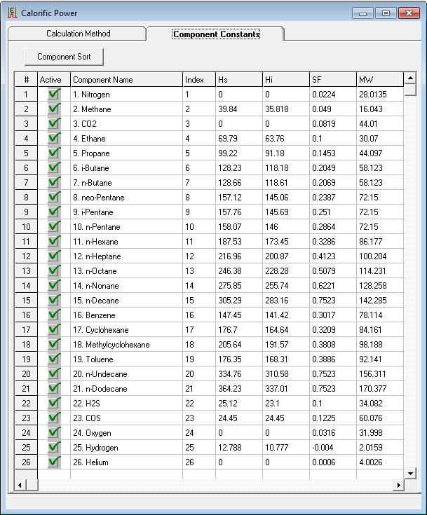
16 2.4 Check of the parameter settings Compare the actual settings in the menu method with the documented settings that are visible in the test report which becomes delivered together with the device. The right starting point for the method to use is this documented factory settings. All parameters in the menus method/instrument Setup, method/integration Events, method/peak Identification, method/peak calibration and method/properties should be the same as in the documented factory settings. If this is the case the first measurements with sample gas can be started. If there is no sample gas available it is also possible to start with some analysis of the calibration gas. Please check especially if the correct standard and correct components constants are used for the country where the devices are installed. An example is the use of the standard ISO 6976 in the state /38
17 17/38

18 If you like to save some measurements for a commissioning protocol don t forget to activate the export to file in the menu method/ advanced. Typically directly after the start-up of the device the measurement results will be unstable, because the device is not thermally stabilized yet. An indicator if the measurement results of the device is stable or not is the unnormalized sum. Directly after start-up the unnormalized sum is typically too high (for example 120 or more). After about one hour (or at least 10 measurements) the results should become stable and than the unnormalized sum should be in a range between 95 and 105. If the unnormalized sum is still too high the set value for the carrier gas pressure is maybe too high or the instrument is still not stable yet. One other cause for a too high unnormalized sum can also be a higher atmospheric pressure or a lower ambient temperature than during the time when the instrument was calibrated for the last time. For a too low value of the unnormalized sum the reason can be a too low carrier gas pressure, a too low gas flow for the carrier gas or a partly blocked carrier gas flow. Another possible reason for a too low unnormalized sum is a much lower ambient pressure than during the last time that the device was calibrated or a much higher ambient temperature than during the time the device was calibrated last time. Also a too low pressure for sample gas or a blocked sample gas flow can be a cause for a too low unnormalized sum. After about one hour the results are quite stable but the temperature inside the housing is not completely stable. Because of that we advice to let the device run for at least 8 hours or over night after start-up and to continue with the preparation of the new basic calibration afterwards. During this time also the rest amount of air and moisture which is often left in the gas tubes for the sample gas becomes completely removed by the sample gas flow. For the biogas device internal moisture filters are used for the first channel from type M5A. At start-up of the device these filters are typically filled with air. Because of that big noise peaks for nitrogen and oxygen are typically visible. With each finished measurement these filters will be flushed with carrier gas more and more and the noise peaks are getting smaller. After several hours the air in the filter is completely removed and the noise peaks will disappear. 18/38


19 2.5 Preparation of a new Basic Calibration The first step is to check the parameter settings in the menu Automation/Sequence. Check here especially if a flushing time of 180 seconds becomes used for every sample gas stream, for the verification and calibration gas. Also the settings in the menu Application/Time Relays for the activation of the internal bypass should be checked. The internal bypass should be activated only if the stream for the analysis becomes changed. It becomes activated a while after the new stream has been selected. The internal bypass should be deactivated again within the parameterized time for flushing (for example after 170 seconds after the change of the stream). Before the new basic calibration becomes started some test measurements with the calibration gas should be done. Important is that the analysis results for the calibration gas is stable enough. Typically at the beginning the nitrogen and the oxygen concentrations are too high and are also unstable. The reason for this effect is that there is often some rest air in the tube for the calibration gas. Continue with the test measurements with the calibration gas until the results are stable. 19/38


20 Stable results for biogas unit are reached when the repeatability for the calculated calorific value better than 0.03% relative standard deviation. For THT device stable results would be better than 0.2ppm relative standard deviation for THT concentration. If the tubes were not flushed well, this would take a few hours. It is possible to speed this up by a manual activation of the internal bypass. This manual activation can be done in the menu Control/ Time Relays. Select 2. Timed Relay 2 and activate it with the button state. This is not possible during a running measurement. Because of that the analysis has to be stopped before the internal bypass can be activated manually. The next step after the test measurements with the calibration gas are finished is to enter the certified values for the calibration gas in the menu method/peak identification. Typically these values should be entered in the column called level 1. 20/38
21 Only if the device has been multilevel calibrated during the production, another calibration level should be used. In this case in the field also just one calibration would be used but the values from the certificate should be entered at level 8 Rw instead of level 1. The next step is to check in the menu method/peak calibration if the option initial calibration is activated and that the total number of calibration levels is 1. Only if the device has been multilevel calibrated before it was delivered the number of calibration levels should be 2 or higher. After the changes in the menu method are finished, don t forget to download the new method to the device. Before the calibration can be started also the settings in the menu automation/ sequence should be checked. 21/38


22 Typically for a calibration three measurements are done, the first one would be ignored and the other two would be used. The average of them would be used for the calculation of the response factors. Check also if the right calibration level becomes used. It must be the same as the used level in the menu method/ peak identification. If you have changed some settings in the menu automation/ sequence the new sequence must be downloaded to the device. Before the new basic calibration can be started the old response factors has to be deleted. This can be done in the menu Control/ Start with a click on the button Recalculate Calibration Curve if the action Clear entire calibration has been selected. After that the basic calibration can be started with a click on the button Execute Calibration Block only. 22/38

23 23/38
24 After the basic calibration is finished the option initial calibration in the menu method/ peak calibration should be deactivated and the option calibration check should be activated. This option becomes used for a check of the daily calibration. The results of the daily calibration will be compared with the results from the basic calibration and from the last valid calibration. If the results are outside the defined limits, which can be parameterized in the menu method/ peak identification, the calibration results becomes discarded and the last valid calibration results would be used for the further analysis. Typically these limits are 5% for the main components and up to 25% for the higher hydrocarbons. 24/38


25 Download the method again after the changes in the menus method/ peak calibration and method/ peak identification are finished. After that a performance test can be started. 2.6 Performance Test The number and the type of gases that can be used for a performance test can be fixed for example in the approval and the corresponding verification procedure. If this is not the case the customer can also propose a performance test of his choice. For a THT device at least the repeatability should be checked with the calibration gas. According to the data sheet the repeatability for THT should always be better than 0.2ppm standard deviation. Some customers are using other limits for the repeatability, for example 2% relative standard deviation. If this is the case this limit should be used for the check of the repeatability. For a biogas device the performance test should be done with three different gases with different amounts for Nitrogen, Methane, Carbon Dioxide and Oxygen. For each of these three test gases a set of measurements (at least 5) should be made. These test results can be reported and used for the commissioning protocol. The results for the heating value and the other calculated results of a biogas device for these three test gases should be better than 0.5% relative deviation to the certified values of the used test gases. If this is the case the results would be acceptable. A possible test result could be like the following example. In this case three test gases with a low and a high heating value were used and the measurement results show that the performance of the device in inside our defined specification for the measurement uncertainty. 25/38

26 If the deviations are bigger than 0.5% for the heating value, it is either possible that some settings in the method are wrong or that the new basic calibration was not good. If the deviations for the calculated results are too big the deviations for the components should also be checked. Find out which components have the biggest deviation. For these components the peak integration should be checked and the entered value for the certified concentration in the menu method/ peak identification should be checked also. If there was a value not correct, a new basic calibration would be needed after the wrong values has been corrected. If the integration of these components is not ok, the settings in the menu method/ peak integration should be adjusted. In the most cases if the integration of a peak is not good the used setting for the parameter Set Threshold is a little too high or the setting for the parameter Set Peak Width is to low. Try some different settings for these parameters to optimize the peak integration. After each change the method must be downloaded to the device and after a recalculation of the actual measurement results the effect for the peak integration is visible. If the optimization of the settings in the method/ peak integration has been finished a new basic calibration would be needed. After the performance test has been successfully finished the last step for the commissioning would be to check the sequence for the operational sample gas analysis. In Sequence Properties the buttons Auto start sequence on power-up and Run sequence continuously should be activated. For the Home Position a stream number where no gas is connected should be used. Because maximal six streams (5 sample + calibration gas) are available this is typically 7. In addition to that the button Stream Ahead Scheduling should be activated. In Calibration Properties a fixed time for the calibration, that becomes typically done once every day, should be selected. 26/38

27 After that start the measurement sequence with the button Full Automation in the menu Control/ Start. 27/38
28 2.7 Check Lists Serial Number Tag Number IP address Certification Number Description KEMA 05ATEX2191X / IECEx KEM X OK? Checked: Yes No Result: Accepted Comments Notes Problems Report(s) when comments: Visual Inspection Analyzer Equipment Visual inspection of the equipment: Action Check for contamination and oxidation (rust) of equipment Check for unusual damages. OK? Checked: Yes No Result: Accepted Comments Notes Problems Report(s) when comments: Check filters and probes Action Result OK? Check probes and filters for contamination. Replace if filters are contaminated. Checked: Yes No Result: Accepted Comments Notes Problems Report(s) when comments: 28/38
29 2.7.3 Set up ENCAL 3000 Description Content and Set point Checked OK Pressure of Carrier gas bottle 1 > 20 Barg Pressure of Carrier gas bottle 2 > 20 Barg (if present) Set Pressure of Carrier gas 5.5 Barg Pressure of Calibration Gas bottle > 20 Barg Set Pressure of Calibration Gas 2 Barg Set Pressure of Sample System 2 Barg Column Temperature Channel 1 Between 50 C and 80 C Column Temperature Channel 2 Between 50 C and 80 C Injector Temperature Channel 1 Between 55 C and 85 C Injector Temperature Channel 2 Between 55 C and 85 C Column Pressure Channel 1 Between 100 and 200 kpa Column Pressure Channel 2 Between 200 and 300 kpa Firmware version 2.20 build or 2.20 build Checked: Yes No Result: Accepted Comments Notes Problems Report(s) when comments: 29/38
30 2.7.4 Check Method Table Encal 3000 According ISO 6976, GPA or GOST Description Preset Checked OK Units KWh /MJ BTU/ KCal Calibration Gas Components Heating Value Calculation according to. Reference and combustion temperature. Remarks: Underlined is as default. According to Calibration Gas Certificate. ISO 6976, GPA, ASTM or Gost (15/15), (0/0), (15/0), (25/0), (20/20), (25/20) for ISO /0 or 20/20 for Gost. 60 F and PSI for GPA and ASTM Checked: Yes No Result: Accepted Comments Notes Problems Report(s) when comments: Calibration Encal 3000 Action Checked OK? Enter the calibration gas data into the method table. From the RGC 3000 software start a calibration run manually. Checked: Yes No Result: Accepted Comments Notes Problems Report(s) when comments: Accuracy Check Encal 3000 Action Result OK? When the Gas Chromatograph is well calibrated, let the Gas Chromatograph run and verify a single analysis with the test gas certificate If difference between measurement and certificate is less than 0.5% on the heating value, it is OK. Checked: Yes No Result: Accepted Comments Notes Problems Report(s) when comments: 30/38
31 2.7.7 Parameter set backup Action Checked OK? Method table saved. Application table saved. Sequence table saved. Modbus table saved. Checked: Yes No Result: Accepted Comments Notes Problems Report(s) when comments: 31/38

32 3 Maintenance To the maintenance of the device belong a visual check for the pressure of the used carrier gases, the calibration gas and the sample gases. In addition to that it is advised to do a manual calibration to be able to check if the daily calibration becomes accepted. Optionally is an additional performance test after the new calibration. For biogas devices the internal moisture filter that are used for the Molesieve channel has to be replaced once a year. In the following picture the connections for the internal moisture filters are marked. These connections has to be opened if a filter becomes replaced. After exchange of the filters these connections has to be closed again. A leakage test with a helium detector has to be done afterwards at these connections. After the filters has been exchanged big nitrogen and oxygen noise peaks will be visible in the chromatogram. The reason for that is that same as at commissioning, the filters are filled with air. The noise peaks will become smaller with each finished measurement. After several hours the filters are completely flushed and the noise peaks will disappear. 32/38
33 3.1 Pressure Check and Visual Check of the Equipment Description Pressure of Carrier gas bottle 1 Pressure of Carrier gas bottle 2 Pressure of Carrier gas Pressure of Calibration Gas bottle Pressure of Calibration Gas Pressure of Sample System Content and Set point > 20 Barg > 20 Barg (if present) 5.5 Barg > 20 Barg 2 Barg 2 Barg If the pressure of the carrier gas or the calibration gas is below these limits it is time to order a new cylinder for the gas that is getting empty. In addition to the pressure of the carrier gas and calibration gas cylinders also a visual check for of the equipment should be done. This covers a check for contamination and oxidation, a check for unusual damages and a check of the probes and filter. If a probe or a filter is contaminated it should be replaced. 3.2 New Calibration and Performance Test If the calibration gas cylinder is nearly empty (< 5 barg), it should be exchanged. In this case the certified values of the new calibration gas cylinder have to be entered in the menu method/ peak identification and a new basic calibration should be done. Otherwise just a normal manually calibration is enough. If this manual calibration becomes not accepted a new basic calibration should be done. For the optional performance test it is possible to use the same kind of gases that were used during the performance test for the commissioning. If the results for the heating value are still within the specification of < 0.5 %, no additional actions are needed. If the deviations are bigger than 0.5% for the heating value it is recommended to do a new basic calibration. 33/38
34 3.3 Checklists first maintenance Pressure Check and Performance Test: Description Min. Content and Set point Actual content OK Pressure of Carrier gas bottle 1 > 20 Barg Pressure of Carrier gas bottle 2 > 20 Barg (if present) Pressure of Carrier gas 5.5 Barg Pressure of Calibration Gas bottle > 20 Barg Pressure of new Calibration Gas bottle if the old one has been replaced > 20 Barg Pressure of Calibration Gas 2 Barg Pressure of Sample System 2 Barg Internal moisture filters exchanged (only for biogas device) New Calibration successful? Performance Test successful? New basic calibration performed if the bottle has been exchanged or if a normal manual calibration was not successful or if the performance test has been failed? Yes No Yes No Visual inspection of the equipment: Action Check for contamination and oxidation (rust) of equipment Check for unusual damages. OK? Checked: Yes No Result: Accepted Comments Notes Problems Report(s) when comments: Action Result OK? Check probes and filters for contamination. Replace if filters are contaminated. Checked: Yes No Result: Accepted Comments Notes Problems Report(s) when comments: 34/38
35 3.4 Checklists second maintenance Pressure Check and Performance Test: Description Min. Content and Set point Actual content OK Pressure of Carrier gas bottle 1 > 20 Barg Pressure of Carrier gas bottle 2 > 20 Barg (if present) Pressure of Carrier gas 5.5 Barg Pressure of Calibration Gas bottle > 20 Barg Pressure of new Calibration Gas bottle if the old one has been replaced > 20 Barg Pressure of Calibration Gas 2 Barg Pressure of Sample System 2 Barg Internal moisture filters exchanged (only for biogas device) New Calibration successful? Performance Test successful? New basic calibration performed if the bottle has been exchanged or if a normal manual calibration was not successful or if the performance test has been failed? Yes No Yes No Visual inspection of the equipment: Action Check for contamination and oxidation (rust) of equipment Check for unusual damages. OK? Checked: Yes No Result: Accepted Comments Notes Problems Report(s) when comments: Action Result OK? Check probes and filters for contamination. Replace if filters are contaminated. Checked: Yes No Result: Accepted Comments Notes Problems Report(s) when comments: 35/38
36 3.5 Checklists third maintenance Pressure Check and Performance Test: Description Min. Content and Set point Actual content OK Pressure of Carrier gas bottle 1 > 20 Barg Pressure of Carrier gas bottle 2 > 20 Barg (if present) Pressure of Carrier gas 5.5 Barg Pressure of Calibration Gas bottle > 20 Barg Pressure of new Calibration Gas bottle if the old one has been replaced > 20 Barg Pressure of Calibration Gas 2 Barg Pressure of Sample System 2 Barg Internal moisture filters exchanged (only for biogas device) New Calibration successful? Performance Test successful? New basic calibration performed if the bottle has been exchanged or if a normal manual calibration was not successful or if the performance test has been failed? Yes No Yes No Visual inspection of the equipment: Action Check for contamination and oxidation (rust) of equipment Check for unusual damages. OK? Checked: Yes No Result: Accepted Comments Notes Problems Report(s) when comments: Action Result OK? Check probes and filters for contamination. Replace if filters are contaminated. Checked: Yes No Result: Accepted Comments Notes Problems Report(s) when comments: 36/38
37 3.6 Checklists fourth maintenance Pressure Check and Performance Test: Description Min. Content and Set point Actual content OK Pressure of Carrier gas bottle 1 > 20 Barg Pressure of Carrier gas bottle 2 > 20 Barg (if present) Pressure of Carrier gas 5.5 Barg Pressure of Calibration Gas bottle > 20 Barg Pressure of new Calibration Gas bottle if the old one has been replaced > 20 Barg Pressure of Calibration Gas 2 Barg Pressure of Sample System 2 Barg Internal moisture filters exchanged (only for biogas device) New Calibration successful? Performance Test successful? New basic calibration performed if the bottle has been exchanged or if a normal manual calibration was not successful or if the performance test has been failed? Yes No Yes No Visual inspection of the equipment: Action Check for contamination and oxidation (rust) of equipment Check for unusual damages. OK? Checked: Yes No Result: Accepted Comments Notes Problems Report(s) when comments: Action Result OK? Check probes and filters for contamination. Replace if filters are contaminated. Checked: Yes No Result: Accepted Comments Notes Problems Report(s) when comments: 37/38
38 3.7 Checklists fifth maintenance Pressure Check and Performance Test: Description Min. Content and Set point Actual content OK Pressure of Carrier gas bottle 1 > 20 Barg Pressure of Carrier gas bottle 2 > 20 Barg (if present) Pressure of Carrier gas 5.5 Barg Pressure of Calibration Gas bottle > 20 Barg Pressure of new Calibration Gas bottle if the old one has been replaced > 20 Barg Pressure of Calibration Gas 2 Barg Pressure of Sample System 2 Barg Internal moisture filters exchanged (only for biogas device) New Calibration successful? Performance Test successful? New basic calibration performed if the bottle has been exchanged or if a normal manual calibration was not successful or if the performance test has been failed? Yes No Yes No Visual inspection of the equipment: Action Check for contamination and oxidation (rust) of equipment Check for unusual damages. OK? Checked: Yes No Result: Accepted Comments Notes Problems Report(s) when comments: Action Result OK? Check probes and filters for contamination. Replace if filters are contaminated. Checked: Yes No Result: Accepted Comments Notes Problems Report(s) when comments: 38/38
Bernhard Thomas September EnCal 3000 prochain Energy in Gas with ROI
 Bernhard Thomas September 2018 EnCal 3000 prochain Energy in Gas with ROI Agenda 1 Introduction The new EnCal 3000 prochain Technical details Outlook Introduction 2 What we measure and why 3 What we measure
Agilent 490 Micro GC Natural Gas Analyzer
 Agilent 490 Micro GC Natural Gas Analyzer User Manual Agilent Technologies Notices Agilent Technologies, Inc. 2012 No part of this manual may be reproduced in any form or by any means (including electronic
Three Columns Gas Chromatograph Analysis Using Correlation between Component's Molecular Weight and Its Response Factor
 Three Columns Gas Chromatograph Analysis Using Correlation between Component's Molecular Weight and Its Response Factor Anwar Sutan, Metco Services Ltd. Charles Johnson, Metco Services Ltd. Jason Laidlaw,
Best Practice Guide, Servomex 2700
 For full installations details refer to the. Best Practice Guide, Servomex 2700 Mounting: General Guidelines: Servomex 2700 Control Units and air supplies (utilities units) should, ideally, be mounted
Technical Bulletin, Communicating with Gas Chromatographs
 Last Updated: 13- July-2010 TB-080000C Technical Bulletin, Communicating with Gas Chromatographs OMNI FLOW COMPUTERS, INC. 12620 West Airport Boulevard, Suite 100 Sugar Land, Texas 77478 United States
Mass Flow Controller (MFC) for Gases
 for Gases") Mass Flow Controller (MFC) for Gases Type 8713 can be combined with... Direct flow measurement by MEMS- Technology for nominal flow rates from 1 ml N /min to 8 l N /min (N 2 ) High accuracy and repeatability
Mass Flow Controller (MFC) for Gases Type 8713 can be combined with... Direct flow measurement by MEMS- Technology for nominal flow rates from 1 ml N /min to 8 l N /min (N 2 ) High accuracy and repeatability
Mass Flow Meter (MFM) for Gases
 for Gases") 873 Mass Flow Meter (MFM) for Gases Direct flow measurement by MEMS- Technology for nominal flow rates from 1 ml N /min to 8 l N /min (N 2 ) High accuracy Short response time Compact design and digital
873 Mass Flow Meter (MFM) for Gases Direct flow measurement by MEMS- Technology for nominal flow rates from 1 ml N /min to 8 l N /min (N 2 ) High accuracy Short response time Compact design and digital
Instruction Manual. BZ7002 Calibration Software BE
 Instruction Manual BZ7002 Calibration Software BE6034-12 Index _ Index Index... 2 Chapter 1 BZ7002 Calibration Software... 4 1. Introduction... 5 Chapter 2 Installation of the BZ7002... 6 2. Installation
Overview. Front Panel: Keypad and Display
 Overview The GA-200B is an analyzer that integrates a gas sampling system with sensors to measure and display the concentrations of oxygen and carbon dioxide in a sample as the percentage of a gas in the
EnCal 3000 Quad Gas Chromatograph Hardware Manual g
 EnCal 3000 Quad Gas Chromatograph Hardware Manual 73022350 g 22.06.2017 EnCal 3000 Quad Hardware Manual 22/06/2017 Contact Information... 3 Safety Information... 4 Gas quality measurement system EnCal
FTC130 Transmitter. Operating Manual
 Seite 1 von 11 FTC130 Transmitter Fast Thermal Conductivity Analyzer Operating Manual 1.09KD180724CWI1V05 Messkonzept GmbH Seite 2 von 11 1. Intended Use... 3 2. Description... 4 3. Measuring gases and
EnCal 3000 Gas Chromatograph Hardware Manual g
 EnCal 3000 Gas Chromatograph Hardware Manual 73022344 g 01.06.2015 EnCal 3000 Hardware Manual 01/06/2015 Contact Information... 3 Safety Information... 4 Gas quality measurement system EnCal 3000... 5
Appendix D: SOP of INNOVA 1412 Photoacoustic Multi-Gas Monitor. Description and Principle of Operation
 Page 1 of 19 : SOP of INNOVA 1412 Photoacoustic Multi-Gas Monitor Description and Principle of Operation The photoacoustic multi-gas monitor (INNOVA 1412, Innova AirTech Instruments, Denmark) is a highly
MEGAS 2.0. Gas analysis with direct C-Level Calculation and Bus-Connection. Data sheet
 Data sheet MEGAS 2.0 Gas analysis with direct C-Level Calculation and Bus-Connection Mesa Industrie-Elektronik GmbH Neckarstraße 19, D-45768 Marl info@mesa-gmbh.de +49 (0) 2365-97 45 1-0 +49 (0) 2365-97
User manual CF8-D/W-IN
 User manual CF8-D/W-IN General The sensor CF8-D/W-IN is used to measure the carbon dioxide concentration inside incubators. All functions can be modified from a PC with the communication cable. UMA 48
Title: Standard Operating Procedure for Measurement of Ethylene (C 2 H 4 ) in Ambient Air by Reduced Gas Detection (RGD)
 in Ambient Air by Reduced Gas Detection (RGD)") Procedure No: SOP-026 Revision No: 1.0 January 24, 2011 Page No.: 1 of 10 1. INTRODUCTION AND SCOPE To obtain timely data for the purpose of air quality assessment, air quality trend reporting and to meet
Procedure No: SOP-026 Revision No: 1.0 January 24, 2011 Page No.: 1 of 10 1. INTRODUCTION AND SCOPE To obtain timely data for the purpose of air quality assessment, air quality trend reporting and to meet
490 Micro GC Site Preparation Checklist
 Thank you for purchasing an Agilent instrument. To get you started and to assure a successful and timely installation, please refer to this specification or set of requirements. Correct site preparation
Multiple Gas#5 GC configuration Jan 2016
 History: Unfortunately there is no single column that can separate: Hydrogen Oxygen Nitrogen Methane CO CO2 Ethane Water Propane Butane Pentane Over the years SRI Instruments has devised several solutions
EnCal 3000 Gas Chromatograph Hardware Manual KC
 EnCal 3000 Gas Chromatograph Hardware Manual 73022344 KC 27.01.2016 EnCal 3000 Hardware Manual 27/01/2016 Contact Information... 3 Safety Information... 4 Gas quality measurement system EnCal 3000... 5
Gases&Technology. Measurement of Impurities in Helium Using the Dielectric Barrier Discharge Helium Ionization Detector. FEATURE.
 Gases&Technology FEATURE Measurement of Impurities in Helium Using the Dielectric Barrier Discharge Helium Ionization Detector. B Y M A T T H E W M O N A G L E Abstract Bulk gases are often delivered to
Operating Manual. SUPREMA Calibration. Software for Fire and Gas Warning Units. Order No.: /01. MSAsafety.com
 Operating Manual Software for Fire and Gas Warning Units Order No.: 10154656/01 MSAsafety.com MSA Europe GmbH Schlüsselstrasse 12 8645 Rapperswil-Jona Switzerland info.ch@msasafety.com www.msasafety.com
UNITY 2 TM. Air Server Series 2 Operators Manual. Version 1.0. February 2008
 UNITY 2 TM Air Server Series 2 Operators Manual Version 1.0 February 2008 1. Introduction to the Air Server Accessory for UNITY 2...2 1.1. Summary of Operation...2 2. Developing a UNITY 2-Air Server method
BIOGAS COMBUSTION PLANT MAINTENANCE MANUAL
 BIOGAS COMBUSTION PLANT MAINTENANCE MANUAL (PLANT MAINTENANCE MANUAL) Puente Gallego Landfill, Rosario (Argentina) ARIA.BIZ S.A. Montevideo 589, 7 floor 1019 Capital federal Argentina Tel: +54 11 5171
Manual of SF6 Comprehensive Tester
 Manual of SF6 Comprehensive Tester Important Description All the staff taking in charge of the usage or maintenance of this product should carefully read this manual. The same as any other complicated
System Overview. TCD Detector temperature setpoint Regulator
 System Overview POPULAR CONFIGURATION GCs Your educational TCD GC is configured on the compact 310 chassis. It is equipped with a TCD Detector, a temperature programmable Column Oven, a 3 Silica Gel packed
Built-in Purge Control Functions
 Built-in Purge Control Functions Why clean a sensor? As the velocity sensor was calibrated clean, operating it clean also preserves the best calibration. Any build up of material on a thermal sensor tends
Mass Flow Controller (MFC) for Gases
 for Gases") Mass Flow Controller (MFC) for Gases Bypass MFC with capillary technology for nominal flow rates from 5 ml N /min to 15 l N /min Applicable for aggressive gases Compact design and digital communication
Mass Flow Controller (MFC) for Gases Bypass MFC with capillary technology for nominal flow rates from 5 ml N /min to 15 l N /min Applicable for aggressive gases Compact design and digital communication
EnCal 3000 Gas Chromatograph Hardware Manual LC
 EnCal 3000 Gas Chromatograph Hardware Manual 73022344 LC 05.10.2016 EnCal 3000 Hardware Manual 05/10/2016 Contact Information... 3 Safety Information... 4 Gas quality measurement system EnCal 3000... 6
Pegas 4000 MF Gas Mixer InstructionManual Columbus Instruments
 Pegas 4000 MF Gas Mixer InstructionManual Contents I Table of Contents Foreword Part I Introduction 1 2 1 System overview... 2 2 Specifications... 3 Part II Installation 4 1 Rear panel connections...
...makes sense! Combined CO 2 /O 2 analyzers. Monitor your process in real-time: OUR CER. BlueSens.com
 ...makes sense! Combined CO 2 /O 2 analyzers Monitor your process in real-time: BlueSens.com OUR CER RQ ...makes sense! The BlueInOne sensor BlueSens is providing modern and inexpensive measuring solutions
This test shall be carried out on all vehicles equipped with open type traction batteries.
 5.4. Determination of hydrogen emissions page 1 RESS-6-15 5.4.1. This test shall be carried out on all vehicles equipped with open type traction batteries. 5.4.2. The test shall be conducted following
Model PDT Dewpoint Transmitter
 Model PDT Dewpoint Transmitter Instruction Manual Alpha Moisture Systems Alpha House 96 City Road Bradford BD8 8ES England Tel: +44 1274 733100 Fax: +44 1274 733200 email: mail@amsytems.co.uk web: www.amsystems.co.uk
973-SF 6 Analyzer. Precise and Stable SF 6 Gas Analyzer REFLECTING YOUR STANDARDS
 Precise and Stable SF 6 Gas Analyzer Simultaneous measurement of humidity, SF 6 purity and SO 2 concentration Integrated gas recovery system with automatic pump back Fully automated SF 6 gas testing Fundamental
The HumiSys. RH Generator. Operation. Applications. Designed, built, and supported by InstruQuest Inc.
 The HumiSys RH Generator Designed, built, and supported by InstruQuest Inc. Versatile Relative Humidity Generation and Multi-Sensor System The new HumiSys with single or dual RH probes capabilities is
Laboratory Hardware. Custom Gas Chromatography Solutions WASSON - ECE INSTRUMENTATION. Engineered Solutions, Guaranteed Results.
 Laboratory Hardware Custom Gas Chromatography Solutions Engineered Solutions, Guaranteed Results. WASSON - ECE INSTRUMENTATION Laboratory Hardware Wasson-ECE Instrumentation offers hardware-only solutions
Energy Management solutions for compressed air and industrial gases. vpinstruments.com
 Energy Management solutions for compressed air and industrial gases vpinstruments.com 6 Introduction VPINSTRUMENTS Measure, Discover and Save! Compressed air is a very expensive energy source. In fact,
490 Micro GC Site Preparation Checklist
 Thank you for purchasing an Agilent instrument. To get you started and to assure a successful and timely installation, please refer to this specification or set of requirements. Correct site preparation
Pneumatic high-pressure controller Model CPC7000
 Calibration technology Pneumatic high-pressure controller Model CPC7000 WIKA data sheet CT 27.63 Applications Automotive and avionics industry Industry (laboratory, workshop and production) Transmitter
SCOPE OF THIS GUIDE STARTING-UP. 1 Check mini CORI-FLOW functional properties
 Quick Installation Guide Doc nr.: 9.17.052H Date: 10-12-2015 SCOPE OF THIS GUIDE mini CORI-FLOW instruments are highly accurate instruments for measuring and controlling the mass flow rate of liquids and/or
Gas Clean. Filters. Delivering Clean Gases for GC and GC/MS Operation
 Gas Clean Filters Delivering Clean Gases for GC and GC/MS Operation Gas Clean Filters Fast, leak-free replacement without tools! Each Gas Clean Filter features a unique quick disconnect design which allows
HYPOXIC AIR FIRE PREVENTION SYSTEM TECHNICAL SPECIFICATION
 HYPOXIC AIR FIRE PREVENTION SYSTEM TECHNICAL SPECIFICATION Introduction: Hypoxic Air Fire Prevention System is a revolutionary fire prevention technology. It has the unique ability to create a breathable
HumiSys HF High Flow RH Generator
 HumiSys HF High Flow RH Generator Designed, built, and supported by InstruQuest Inc. Versatile Relative Humidity Generation and Multi-Sensor System The HumiSys HF is a high flow version of the previously
Laboratory Hardware. Custom Gas Chromatography Solutions WASSON - ECE INSTRUMENTATION. Custom solutions for your analytical needs.
 Laboratory Hardware Custom Gas Chromatography Solutions Custom solutions for your analytical needs. Laboratory Hardware Wasson-ECE Instrumentation offers hardware-only solutions for advanced chromatography
X-dock Software History
 X-dock Software History SW Version Bugfixes Features 01.01.01 01.02.2013 01.01.02 01.02.2013 01.02.05 04.03.2013 01.02.10 Start of history Pac 7000 support with FW 4.0 (older firmware locked) Improvements
Technical Data Sheet MF010-O-LC
 Technical Data Sheet MF010-O-LC - 1 - 1. Properties The oxygen measuring system MF010-O-LC determines the oxygen content in gas mixtures up to a temperature of 250 C. It is particularly suitable for the
TYPE DOSAODOR-D SOFTWARE FOR CONFIGURATION OF TYPE DOSAODOR-D ODORANT INJECTION SYSTEM
 User Manual Type Dosaodor-D November 2009 TYPE DOSAODOR-D SOFTWARE FOR CONFIGURATION OF TYPE DOSAODOR-D ODORANT INJECTION SYSTEM Figure 1. ROCLINK 800 Odorizer System Software D103117X012 O.M.T. www.emersonprocess.com/regulators
In Response to a Planned Power Outage: PPMS EverCool II Shut Down and Re-start Procedure
 PPMS Service Note 1099-412 In Response to a Planned Power Outage: PPMS EverCool II Shut Down and Re-start Procedure Introduction: Loss of electricity to the PPMS EverCool II should not cause damage to
MODEL CALIBRATION GAS DELIVERY SYSTEM
 MODEL 1200-26 CALIBRATION GAS DELIVERY SYSTEM Sierra Monitor Corporation 1991 Tarob Court, Milpitas, CA 95035 (408) 262-6611 MODEL 1200-26 CALIBRATION GAS DELIVERY SYSTEM APPLICABILITY & EFFECTIVITY This
better measurement Simply a question of SCHMIDT Flow Sensor SS The cost-effective alternative in pressurised systems up to 10 bars.
 Simply a question of better measurement SCHMIDT Flow Sensor SS 20.261 The cost-effective alternative in pressurised systems up to 10 bars. Compressed air technology Industrial processes A cost analysis
Pneumatic high-pressure controller Model CPC7000
 Calibration technology Pneumatic high-pressure controller Model CPC7000 WIKA data sheet CT 27.63 Applications Healthcare and avionics industry Industry (laboratory, workshop and production) Transmitter
GCMSD-Headspace Analysis SOP
 Before you start GCMSD-Headspace Analysis SOP Method and Sequences names are restricted to 50 characters (MSD program will crash otherwise) The GC oven and Injection Ports need to be cooled to 50 oc to
Plasma. Argon Production Helium Liquefaction Truck Loading Pure Gas Bottling
 SERVOPRO Plasma The SERVOPRO Plasma is a Plasma Emission Detector based analyser designed to continuously measure Nitrogen in pure Argon for process and quality control in Argon production within Cryogenic
EuroFID Total Hydrocarbon Analyzer. Precise Determination of Total Hydrocarbons in Air for Corrosive as well as Condensing Gases
 P r o d u c t i n f o r m at i o n EuroFID Total Hydrocarbon Analyzer Precise Determination of Total Hydrocarbons in Air for Corrosive as well as Condensing Gases Proven Analyzer Technology Measuring total
Inert Air (N2) Systems Manual
 Systems Manual") INSTRUCTION MANUAL Inert Air (N2) Systems Manual N2-MANUAL 2.10 READ AND UNDERSTAND THIS MANUAL PRIOR TO OPERATING OR SERVICING THIS PRODUCT. GENERAL INFORMATION Positive pressure nitrogen gas pressurizing
INSTRUCTION MANUAL Inert Air (N2) Systems Manual N2-MANUAL 2.10 READ AND UNDERSTAND THIS MANUAL PRIOR TO OPERATING OR SERVICING THIS PRODUCT. GENERAL INFORMATION Positive pressure nitrogen gas pressurizing
EnCal 3000 Gas Chromatograph Hardware Manual
 EnCal 3000 Gas Chromatograph Hardware Manual Index Index...1 Contact Information...2 Safety Information...3 1 Process Gas Chromatography General Introduction...4 1.1 Gas Chromatography : Analytical Principle...
Application Note. Rapid performance verification of AZURA systems with refractive index detector. Summary. Introduction
 Application Note Rapid performance verification of AZURA systems with refractive index detector Method Keywords ID HPLC Quality control, system verification, refractive index, AZURA Analytical HPLC Plus
Helium Level Measurement Unit
 Helium Level Measurement Unit HLMU User Manual Version 002 The information in this manual may be altered without notice. BRUKER BIOSPIN accepts no responsibility for actions taken as a result of use of
Calibration of a GC955
 Calibration of a GC955 1 Contents of the power point instructions Standard calibration Automatic validation methods and calibration of multi component mixes Autolinearisation: test of the linearity of
BUBBLER CONTROL SYSTEM
 BUBBLER CONTROL SYSTEM Description: The HDBCS is a fully automatic bubbler system, which does liquid level measurements in water and wastewater applications. It is a dual air compressor system with, air
Discovery HP-TGA 75/750. Site Preparation Guide
 Discovery HP-TGA 75/750 Site Preparation Guide Revision A Issued August 2018 Table of Contents Table of Contents... 2 Ideal Setup... 3 System Components... 4 Instrument Measurements... 5 Utility Requirements...
Operating Instructions DB41
 PKP Process Instruments Inc. 10 Brent Drive Hudson, MA 01749 Tel: +1-978-212-0006 Fax: +1-978-568-0060 PKP Prozessmesstechnik GmbH Borsigstrasse 24 D-65205 Wiesbaden-Nordenstadt Tel: 06122 / 7055-0 Fax:
Performance Overview calibration Laboratory EP Instruments Messtechnik und Kalibrierung GmbH
 Performance Overview calibration Laboratory EP Instruments Messtechnik und Kalibrierung GmbH 1 D-K-15143-01-00 Services around the measurement technology in Germanys most accurate DAkkS laboratory*. Whether
ISO INTERNATIONAL STANDARD
 INTERNATIONAL STANDARD ISO 6974-4 First edition 2000-04-01 Natural gas Determination of composition with defined uncertainty by gas chromatography Part 4: Determination of nitrogen, carbon dioxide and
PGA3510 Portable 3-Gas IR Analyzer. Operations Manual
 PGA3510 Portable 3-Gas IR Analyzer Operations Manual Please read, understand, and follow these instructions before operating this equipment. Super Systems, Inc. is not responsible for damages incurred
GA-300 Gas Analyzer. Technical Note. Overview. Front Panel. iworx Systems, Inc. GA-300
 Technical Note GA-300 Overview The GA-300 CO2 and O2 Gas Analyzer is easy to use, robust, and adaptable to human, animal, and plant applications. The GA-300 has two analog outputs to allow recording and
Operation & Maintenance Manual GDS-68XP
 Operation & Maintenance Manual GDS-68XP Process Gas Monitor for Low Oxygen Applications GDS Corporation 2513 Hwy 646 Santa Fe, Texas 77510 (409) 927-2980 (409) 927-4180 (Fax) www.gdscorp.com CAUTION: FOR
Ultima. X Series Gas Monitor
 Ultima X Series Gas Monitor Safety Manual SIL 2 Certified " The Ultima X Series Gas Monitor is qualified as an SIL 2 device under IEC 61508 and must be installed, used, and maintained in accordance with
Mass Flow Meter (MFM) for gases
 for gases") Mass Flow Meter (MFM) for gases Type can be combined with Inline MFM for nominal flow rates from 25 l N /min to 1,500 l N /min; 1/4 to 3/4 High accuracy Fast settling time Fieldbus option Special version
Mass Flow Meter (MFM) for gases Type can be combined with Inline MFM for nominal flow rates from 25 l N /min to 1,500 l N /min; 1/4 to 3/4 High accuracy Fast settling time Fieldbus option Special version
Title: Standard Operating Procedure for Elemental and Organic Carbon (EC and OC) using Non-Dispersive Infrared Detection (NDIR)
 using Non-Dispersive Infrared Detection (NDIR)") Procedure No: SOP-025 Revision No: 1.0 (January 21, 2011) Page No.: 1 of 8 1. INTRODUCTION AND SCOPE To obtain timely data for the purpose of air quality assessment, air quality trend reporting and to
Procedure No: SOP-025 Revision No: 1.0 (January 21, 2011) Page No.: 1 of 8 1. INTRODUCTION AND SCOPE To obtain timely data for the purpose of air quality assessment, air quality trend reporting and to
Operation of the Perkin Elmer TGA-GC/MS
 Operation of the Perkin Elmer TGA-GC/MS Summary of the TGA-GC/MS: The TGA-GC/MS allows a user to decompose a sample by heating, measure its loss of mass, and simultaneously analyze the chemical composition
FUNDAMENTALS OF GAS CHROMATOGRAPHY, GAS QUALITY & TROUBLESHOOTING Larry Ewing Chandler Engineering Company LLC
 FUNDAMENTALS OF GAS CHROMATOGRAPHY, GAS QUALITY & TROUBLESHOOTING Larry Ewing Chandler Engineering Company LLC 2001 N. Indianwood Avenue, Broken Arrow, OK 74012 INTRODUCTION Measurement of the quality
Your local gas generation partner. Precision series Modular gas generation solution for GC.
 Your local gas generation partner Precision series Modular gas generation solution for GC www.peakscientific.com Perform with Precision Specifically designed and engineered for GC laboratory applications,
Mr Roger Wood Measurement & Process Group (M&P) Network Strategy National Grid Gas plc Brick Kiln Street Hinckley Leicestershire LE10 0NA
 Network Strategy National Grid Gas plc Brick Kiln Street Hinckley Leicestershire LE10 0NA") Mr Roger Wood Measurement & Process Group (M&P) Network Strategy National Grid Gas plc Brick Kiln Street Hinckley Leicestershire LE10 0NA Dear Roger, Your Ref: Our Ref: Direct Dial: 020 7901 7468 Email:
Mr Roger Wood Measurement & Process Group (M&P) Network Strategy National Grid Gas plc Brick Kiln Street Hinckley Leicestershire LE10 0NA Dear Roger, Your Ref: Our Ref: Direct Dial: 020 7901 7468 Email:
Model Description
 LEAKHUNTER Plus LEAKHUNTER Plus Model 8066 Description The MATHESON LEAKHUNTER Plus is a truly universal leak detector. Extensive R&D has produced a multi-functional leak detector engineered to perform
General Specifications: Forensic. Petrochemical Environmental. Lab Quality Analyses in the Field, It Goes with you Anywhere!
 The portable Gas Chromatograph is now more versatile than ever. DPS Instruments is pleased to present the newest Portable Companion 2 Gas Chromatograph with room for 2 Detectors. The Companion 2 GC was
Dräger X-dock Frequently Asked Questions
 COSTS Why do I save costs when using Dräger X-dock? SOFTWARE What are the benefits of using a central database? What is the difference between the X-dock Manager Standard and the Professional Version?
PERFORMANCE SPECIFICATION PROPELLANT, HYDROGEN
 METRIC 17 May 2013 SUPERSEDING MIL-PRF-27201D 07 February 2007 PERFORMANCE SPECIFICATION PROPELLANT, HYDROGEN This specification is approved for use by all Departments and Agencies of the Department of
Title: Standard Operating Procedure for R&R Environmental Devices Model MFC201 Gas Dilution Calibrator
 Procedure No: SOP-029 Revision No: 1.1 (December 29, 2010) Page No.: 1 of 7 1. INTRODUCTION AND SCOPE To obtain timely data for the purpose of air quality assessment, air quality trend reporting, air quality
GasSense NDIR User Manual
 INDEX INDEX... 1 1. OVERVIEW... 2 2. TECHNICAL DATA... 3 3. SPECIFICATIONS... 4 4. PRODUCT DESCRIPTION... 5 4.1 Mechanical details... 5 4.2 Piping... 7 4.3 Connections... 7 5. INSTALLATION... 10 6. CALIBRATION
5890II GC Standard Operating Procedure 9/2/2005
 5890II GC Standard Operating Procedure 9/2/2005 This procedure is for the analysis of natural gas using the HP 5890II GC with the Restek ShinCarbon column. Detector Type: TCD Column Type: Restek Micropacked,
Hot extractive multi-channel gas analyser for continuous process and emissions monitoring.
 Product Data Sheet CODEL Continuous Emission Monitoring GCEM4100 Extractive Gas Analyser CO, CO2, NO, NO2, SO2, HCL, CH4 & H2O Hot extractive multi-channel gas analyser for continuous process and emissions
Quick Installation Guide Doc nr.: C Date:
 Quick Installation Guide Doc nr.: 9.17.093C Date: 13-05-2016 SCOPE OF THIS GUIDE mini CORI-FLOW instruments are highly accurate instruments for measuring and controlling the mass flow rate of liquids and/or
Instruction manual. for. high purity gas pigtails 200 bar / 300 bar
 Instruction manual for high purity gas pigtails 200 bar / 300 bar Contents Contents... 2 1. Preface... 3 1.1 Overview... 3 1.2 General... 3 1.3 Intended use... 4 1.4 Personnel requirements... 4 2. For
Instruction Manual. Model DSP-Ex Portable Dewpoint Meter. Alpha Moisture Systems Alpha House 96 City Road Bradford BD8 8ES England
 Model DSP-Ex Portable Dewpoint Meter Instruction Manual Alpha Moisture Systems Alpha House 96 City Road Bradford BD8 8ES England Tel: +44 1274 733100 Fax: +44 1274 733200 Email: info@amsytems.co.uk Web:
KIV-SACS Safe automatic calibration system:
 KIV-SACS Safe automatic calibration system: LOK: g:\prosjekter\calibration_system\kiv safe calibration system.doc Page: 1 of 14 Parts description:... 4 Wash extractors:... 6 Tunnel washers:... 5 Test valve:...
AUTOMATIC HOSE TEST UNIT, TYPE SPU
 VALVES AND FITTINGS UP TO 14,000 BAR TEST AND CONTROL EQUIPMENT H IGH PRESSURE TECHNOLOGY AUTOMATIC HOSE TEST UNIT, TYPE SPU Pressure range from 1 up to 10,000 bar User-friendly touch panel operation HIGH-PRESSURE
Hot extractive multi-channel gas analyser for continuous process and emissions monitoring.
 Product Data Sheet CODEL Continuous Emission Monitoring GCEM4100 Extractive Gas Analyser CO, CO2, NO, NO2, SO2, HCL, CH4 & H2O Hot extractive multi-channel gas analyser for continuous process and emissions
Specifications and information are subject to change without notice. Up-to-date address information is available on our website.
 www.smar.com Specifications and information are subject to change without notice. Up-to-date address information is available on our website. web: www.smar.com/contactus.asp LD302 - AssetView HMI LD302
Technical Information Conducal CLY421
 TI00496C/07/EN/01.12 71142150 Products Solutions Services Technical Information Conducal CLY421 Conductivity calibration set for ultrapure water applications Factory calibrated measurement box Certified
The HumiPyc - Model 1 - Gas Pycnometer; Density, Moisture, Permeation Analyzer; RH sensor Calibrator
 The HumiPyc - Model 1 - Gas Pycnometer; Density, Moisture, Permeation Analyzer; RH sensor Calibrator Designed, built, and supported by InstruQuest Inc. Temperature controlled, multi-technique volumetric
Spot the Hazards: Review Confined Space Hazards Missed by Most Safety Professionals, and the PPE Solutions that Meet OSHA Requirements
 Spot the Hazards: Review Confined Space Hazards Missed by Most Safety Professionals, and the PPE Solutions that Meet OSHA Requirements Why is Gas Detection Important? Spot the hazard Composition of Fresh
KEM Scientific, Inc. Instruments for Science from Scientists
 KEM Scientific, Inc. Instruments for Science from Scientists J-KEM Scientific, Inc. 6970 Olive Blvd. St. Louis, MO 63130 (314) 863-5536 Fax (314) 863-6070 E-Mail: jkem911@jkem.com Precision Vacuum Controller,
Gas Module for Series GMS800
 Title Page SUPPLEMENTARY OPERATING INSTRUCTIONS Gas Module for Series GMS800 Components Application Information Operating Data Document Information Described Product Product name: Gas Module Basic device:
OPTIMA 7 - BIOGAS Calibrating the gas sensors SENSOR ADJUSTMENT. Diamond Scientific 625 Peachtree St., Cocoa, Florida /Tel:
 SENSOR ADJUSTMENT The calibration of your OPTIMA 7 should be performed by experienced service personal only! MRU will not be responsible for any misuse or wrong interpretation of this calibration instruction.
1. Functional description. Application program usage. 1.1 General. 1.2 Behavior on bus voltage loss and bus voltage. 1.
 Application program usage product family: Product type: Manufacturer: Name: Order-No.: Valve actuators Constant valve actuator Siemens Valve actuator AP 562/02 5WG1 562-7AB02 Commissioning For commissioning
AMT-Ex Dewpoint Transmitter
 AMT-Ex Dewpoint Transmitter Instruction Manual Alpha Moisture Systems Alpha House 96 City Road Bradford BD8 8ES England Tel: +44 1274 733100 Fax: +44 1274 733200 email: mail@amsytems.co.uk web: www.amsystems.co.uk
6850 Series Control Module User Information
 6850 Series Control Module User Information Contents Introduction Important Information...4 Overview...4 Control Module elements...5 Navigating the screens...8 Configuring the instrument...12 To adjust
Customer Responsibilities
 Thank you for purchasing an Agilent instrument. To get you started and to assure a successful and timely installation, please refer to this specification or set of requirements. Correct site preparation
Transmitter CS 21 Operation Manual
 Transmitter CS 21 Operation Manual Content Page For your Safety 3 General Description 3 Detection Principle 4 Operational Notes 4 Design 4 Mounting Position of CS21 5 Mounting 6 Installation of Electrical
MASS FLOW SYSTEMS MASS FLOW MEASURING, CONTROLLING AND BLENDING SYSTEMS
 MASS FLOW SYSTEMS MASS FLOW MEASURING, CONTROLLING AND BLENDING SYSTEMS Using state-of-the-art measuring and microprocessor technologies, Advanced has assembled a series of systems which can measure mass