CO 2 dehydration after CO 2 capture
|
|
|
- Clinton Jordan
- 5 years ago
- Views:
Transcription

1 University College of Southeast Norway Faculty of Technology Master s Thesis Process, Energy and Environmental Technology Spring 2016 Birendra Rai CO 2 dehydration after CO 2 capture
2 University College of Southeast Norway Faculty of Technology Department of Process, Energy and Environmental Technology Kjølnes Ring Porsgrunn, Norway Birendra Rai 2
3 MASTER S THESIS, COURSE CODE FMH606 Student: Thesis title: BIRENDRA RAI CO2 DEHYDRATION AFTER CO2 CAPTURE Signature: Number of pages: 74 Keywords: CO2, triethylene glycol, dehydration, Aspen HYSYS, process simulation Supervisor: LARS ERIK ØI Sign.: Censor: ANETTE MATHISEN Sign.: External partner: Sign.: Availability: Open Archive approval (supervisor signature): Sign.: Date : Abstract: The presence of free water is considered as one of the major impurities for the pipeline transportation of gas. Corrosion and hydrate formation in the process plant equipment are common problems associated with the free water. The gas dehydration process has been the most preferred method. Water absorption followed by glycol regeneration are the key stages of a gas dehydration unit. Although, being in operation for a long period of time there are no rationale standards for water content requirements in the dehydration of gas. Water specifications between 5 and 500 ppm (parts per million) are generally considered. Only a few references have been published on simulation of CO 2 dehydration based on absorption in glycol. All the simulations have been performed in Aspen HYSYS version 8.0 using Peng-Robinson (PR) and Twu-Sim-Tassone (TST) equilibrium models. The results from the TST model are considered to be the most accurate for glycol dehydration. Several parameters such as absorption pressure, glycol flow rate, number of absorption stages, and stripping gas flow rate were varied to simulate their effects on water removal efficiency. The simulation results of a traditional triethylene glycol dehydration process showed optimum dehydration efficiency at a pressure of 5000 kpa with resulting water content of 129 ppm using PR and 105 ppm using TST model. The traditional dehydration process was enhanced by introducing stripping gas to the reboiler and by adding an extra stripping column. Simulations show that injecting stripping gas to the reboiler can dehydrate gas down to 30 ppm. With an additional extra stripping column, water content was reduced down to about 1 ppm. A Drizo process was also simulated which calculated less than 1 ppm water in dehydrated CO 2. University College of Southeast Norway accepts no responsibility for results and conclusions presented in this report. 3
4 Contents 1 Introduction Background of gas dehydration CO2 dehydration Corrosion and Hydrate formation Objective of the thesis Literature review Water specifications Triethylene Glycol (TEG) as an absorbent Gas dehydration methods TEG dehydration alternatives Vapour/Liquid equilibrium models Previous work of TEG dehydration of natural gas Previous work of TEG dehydration of carbon dioxide Industries and TEG dehydration unit vendors Process description Selection of CO2 dehydration process Traditional TEG dehydration process Enhanced TEG dehydration process Stripping gas to the reboiler Stripping gas to the extra stripping column Drizo Process simulation Base case Variation of inlet gas pressure Variation of lean TEG flow rate
5 4.1.3 Base case simulation including flash tank TEG regeneration enhancement Stripping gas to the reboiler Flash gas as stripping gas to the reboiler Regeneration and extra stripping column simulated as one column Simulation of Drizo process Discussion Verification of previous simulation results and deviations Comparison of Peng-Robinson and Twu-Sim-Tassone Optimum dehydration pressure Evaluation of simulations Choice of process dependent on dehydration requirement Conclusion References Appendices
6 Preface This thesis is written as a part of the Master program in Energy and Environmental Technology at University College of Southeast Norway, during the spring semester The task description is presented in Appendix 1. First and foremost, I wish to express my sincere gratitude towards my supervisor, Professor Lars Erik Øi. It would not have been possible to complete my work without his advice, guidance and supervision. I highly appreciate his knowledge, experience and significant contributions to CO2 Capture research. Above all, I want to thank my beloved family who motivated and supported me unconditionally throughout my two years stay in Norway. I am thankful to my colleagues and friends at University College of Southeast Norway for always being helpful and cooperative. I will thank all the staffs from the Library of University College of Southeast Norway for providing books, databases and journal articles relevant to my thesis. I appreciate the IT Service for providing updated version of Aspen HYSYS and also for making the library electronic resources accessible freely on and off campus. Last but not the least, I gratefully acknowledge all my country fellows for their friendly suggestions and guidance during my difficult times. Porsgrunn, 3 rd June 2016 Birendra Rai 6
7 List of figures Figure 1.1: Gas dehydration process as a part of Gas Treatment Plant Figure 1.2: Annual corrosion rates of two different specimens as a function of water content Figure 1.3: Hydrate formation temperature as a function of water content Figure 2.1: Solubility of water in CO2 as a function of pressure and temperature Figure 2.2: Adsorption process Figure 2.3: Membrane process Figure 2.4: Mechanical Refrigeration (Condensation) process Figure 2.5: Coldfinger condenser process Figure 2.6: Water dew point depression in accordance to TEG purity Figure 3.1: Traditional Triethylene glycol dehydration process Figure 3.2: TEG dehydration process with stripping gas to reboiler Figure 3.3: TEG dehydration process with an extra stripping column in the TEG regeneration system Figure 3.4: TEG dehydration process by Drizo process Figure 4.1: Aspen HYSYS flow-sheet model for traditional TEG dehydration process. 42 Figure 4.2: Water content in dehydrated gas as a function of absorption pressure Figure 4.3: Water content in dehydrated gas as a function of lean TEG flow rate Figure 4.4: Aspen HYSYS flow-sheet model for traditional TEG dehydration process including flash tank Figure 4.5: Aspen HYSYS flow-sheet model with stripping gas introduced to the reboiler Figure 4.6: Water content as a function of stripping gas and number of absorber stages with stripping gas to the reboiler using PR and TST models Figure 4.7: Water content as a function of stripping gas and number of absorber stages(5,10,15 and 20) with stripping gas to the reboiler using PR and TST models
8 Figure 4.8: Aspen HYSYS flow-sheet model with flash gas as stripping gas to the reboiler Figure 4.9: Aspen HYSYS flow-sheet model of desorption column and extra stripping column simulated as one column Figure 4.10: Water content as a function of stripping gas and number of stages with desorption column and stripping column simulated as one using Peng-Robinson and Twu-Sim-Tassone Figure 4.11: Water content as a function of stripping gas and number of absorber stages (5,10,15 and 20) with extra stripping column using PR and TST models Figure 4.12: Aspen HYSYS flow-sheet model of regeneration column and extra stripping column simulated as one with portion of dehydrated CO2 as stripping gas Figure 4.13: Water content as a function dehydrated CO2 as stripping gas with regeneration column and stripping column simulated as one using PR and TST Figure 4.14: Water content as a function of stripping gas (dehydrated CO2) and number of absorber stages (5,10,15 and 20) with extra stripping column using PR and TST Figure 4.15: Aspen HYSYS flow-sheet model of regeneration column and extra stripping column simulated as one with flash gas as stripping gas Figure 4.16: Aspen HYSYS flow-sheet model of Drizo process using n-heptane as stripping gas Figure 4.17: Water content in Drizo process with benzene, toluene and n-heptane as a function of stripping gas and number of absorber stages using TST model
9 List of tables Table 2.1: Physical properties of MEG, DEG, TEG, TREG Table 2.2: Peng-Robinson parameters Table 2.3: Glycol package parameters Table 2.4: Binary interaction parameters for use in TST model (TEG/H2O) Table 2.5: Specifications and Technical details of Stublach Gas Storage Project UK carried out by Frames Table 2.6: List of Projects Table 4.1: Critical parameters Table 4.2: Base case specifications for TEG dehydration of CO Table 4.3: Results of TEG dehydration of CO2 including flash tank Table 4.4: Simulation results of flash gas as a stripping gas to the reboiler Table 4.5: Simulation results of flash gas as a stripping gas to extra stripping column simulated as one with regeneration column simulated as one
10 Abbreviation CCS CO2 MEG DEG TEG TREG EOS EOR ppm PR TST SRK CPA HC BTEX T VLE EIGA Carbon Capture and Storage Carbon-dioxide Mono-ethylene Glycol Di-ethylene Glycol Triethylene Glycol Tetra-ethylene Glycol Equation of state Enhanced Oil Recovery Parts per million Peng-Robinson Twu-Sim-Tassone Soave-Redlich-Kwong Cubic-Plus-Association Hydrocarbon Benzene, Toluene, Ethyl benzene and Xylene Temperature Vapour-Liquid equilibrium European Industrial Gases Association 10
11 1 Introduction 1.1 Background of gas dehydration The rapid advancement in energy and industrial sectors have increased the atmospheric concentration of carbon dioxide in the environment. Global warming and climate change are the hot issues in the present situation. Various researches and experiments have been carried out for the optimization of Carbon Capture and Storage (CCS). Also, to compensate the increasing demand for crude oil, the potential usage of gas in large scale applications has risen up. They are more focused on capturing harmful greenhouse gases of which CO2 is the major one and make the best use of them as it will eventually contribute to controlling the global temperature. Gas dehydration is the process of removing water from the gas stream. Before exporting CO2 from the production area to the consumption locations certain water specifications of the produced/captured gas have to be fulfilled. Since all gas streams are fully/partially saturated at initial phase, gas streams need to be subjected to the dehydration process before supplying to the commercial market. The main target of this process is to avoid corrosion and hydrates formation in the transportation equipment. Figure 1.1: Gas dehydration process as a part of Gas Treatment Plant 11
12 The timeline below shows the historical background of gas dehydration [1] 1929 Glycerol was the first liquid desiccant used for dehydrating fuel gas Calcium chloride solution was the first liquid desiccant used for natural gas dehydration Diethylene glycol was first used for dehydrating natural gas. Also, triethylene glycol was proved to be the most effective dehydrating desiccant At least 5,000 natural gas dehydration plants based on glycol absorption were estimated to be in operation in U.S. and Canada More than 20,000 plants are estimated to be in operation. 1.2 CO 2 dehydration CO2 dehydration process is same as natural gas dehydration process where the dominating gas will be carbon-dioxide. In recent years, CO2 dehydration has become matter of interest due to the high demand of water free (pure) CO2 in enhanced oil recovery projects. The CO2 gas streams are usually captured at low pressure from the carbon capture system. While transporting CO2 through the pipelines or during the storage period, it has to meet certain specifications including optimum water dew point, maximum hydrocarbon dew point, allowable concentrations of solids content and contaminants. The presence of water vapour in the gas streams has been a major threat for the storage tanks and transportation pipeline walls. The CO2 dehydration processes are generally performed by; Absorption by liquid desiccants (Triethylene glycol) Adsorption by solid desiccants (Molecular sieve) Membrane processes Refrigeration The water specifications, energy consumption, operating conditions, safety and environmental standards are the governing factors for the choice of dehydration. CO2 dehydration based on glycol absorption is discussed in this work. 12

13 1.3 Corrosion and Hydrate formation When CO2 comes in contact with water, it is partly hydrated and carbonic acid (carbonates and bicarbonates) is formed. This is a weak acid with moderate ph value. At high pressure, the degree of dissociation increases which makes it stronger. It results in the corrosion of pipelines and compressor materials. Presence of impurities and inert will boost corrosion and also have the adverse effects on vapour/liquid equilibrium. In absence of free water in pure dense phase CO2, corrosion rate in carbon steel is almost zero. For longer distances, use of highly corrosion resistant materials 1 (stainless steel) for transport pipeline would not be economically feasible. Safe transport and durability of transport infrastructures can be ensured below the water solubility limit (500 ppm) in CO2 i.e. corrosion, hydrate formation and free water formation will be minimum [2]. Numerous modelling and experimental results based on CO2 corrosion from various researches are reviewed in [3]. However, the definite mechanisms of corrosion in carbon steel CO2 pipelines due to water have not been entirely understood. From the Figure 1.2, it can be observed that the corrosion rates are minimum for the sufficiently dry CO2. Figure 1.2: Annual corrosion rates of two different specimens as a function of water content [4] 1 Stainless steels are economically feasible only for wet CO 2 for a relatively small distance. (Sleipner project) [2] E. Visser de, C. Hendriks, G. Koeijer de, S. Liljemark, M. Barrio, A. Austegard, et al., "DYNAMIS CO2 quality recommendations,"

14 Hydrates are solid, complex, crystalline compounds formed by the combination of free water with molecules like CO2, H2S, and CH4. High pressure and low-temperature favour hydrate formation. Hydrates are generally formed at temperatures above the freezing point in both liquid and vapour phase. Methanol and other hydrate inhibitors are typically used to avoid hydrate formation in pipelines. However, due to their inability to reduce the water content as prescribed requirements, they are only used for relatively short distance where hydrate avoidance is crucial [5]. Figure 1.3: Hydrate formation temperature as a function of water content [5] Corrosion of walls of the transmission pipelines as well as storage tanks and plugging of pipelines of the process equipment due to the hydrate formation are the serious operational problems of water vapour present in the gas streams [1]. Furthermore, it creates a dramatic reduction in the efficiency and capacity of the pipelines. Appropriate selection of non-corrosive materials 2, regular monitoring programs, and injection of hydrate inhibitors could avoid corrosion and hydrate formation. But these 2 Use of non-corrosive materials (stainless steel) would be economically unfeasible for pipeline transportation beyond 1 km length. 14
15 preventive measures are often expensive and impractical based on process scheme and design considerations. These problems can also be avoided by keeping the gas stream above the dew point. Therefore, it is essential to know the specific water vapour content of the gas and the conditions under which hydrates are formed [6]. On the other hand, the moisture prediction charts 3 [6] are also considered as a helpful medium to determine the quantity of water vapour at saturation condition with various pressure and temperature [5].Therefore, dehydration of CO2 before transmission is almost inevitable. Although the dehydration process is relatively small part with respect to full CO2 capture system, several challenges need to be addressed before full-scale deployment of the gas treatment plants [7]. 1.4 Objective of the thesis The main objective of this thesis is to simulate the CO2 dehydration process by absorption in triethylene glycol (TEG) using Aspen HYSYS process simulation program. To evaluate the simulation results of numerous process conditions and compositions using Peng-Robinson (PR) and Twu-Sim-Tassone (TST) equilibrium models. Also, to demonstrate the potentialities of TEG dehydration process as an alternative to other expensive dehydration processes. In the available literature, most of the dehydration processes in various oil and gas processing industries are developed for natural gas. There are no specific companies or vendors that claim supplying of TEG dehydration unit for CO2 dehydration. Also, most of them have not even disclosed the dehydration capacity of their unit. Moreover, the equilibrium models are developed based on the relevant experimental data and field/operational data obtained from the natural gas. Therefore, several valid issues need to be resolved to achieve cost-efficient water concentration limit. 3 The chart is presented in Appendix 3. They are only applicable for acid gas streams and not for sour gas streams. 15
16 2 Literature review 2.1 Water specifications The water content of gas is commonly referred in terms of water dew point. The water dew point is the temperature at which the water just initiates to condense. Determination of water content in the gas is an important aspect of gas dehydration process. The water solubility in CO2 is greatly influenced by the variation in pressure and temperature. From Figure 2.1, it can be seen that there will be a significant reduction in the solubility of water in CO2 when CO2 changes from liquid to vapour phase. But after certain pressure limit i.e. when there is a transition from vapour to liquid, there will be a considerable increase in the solubility of water in CO2. When comparing the variation in pressure and temperature parameters, variation in temperature has the most prominent influence on the water solubility. The increment in pressure of magnitude 1 bar raises the water solubility by 3-4 ppm whereas, an increment in temperature of 1ºC raises the water solubility by 50 ppm [8]. Several evaluations for the prediction of solubility of water in CO2 by the various equation of state models can be found in [9]. Figure 2.1: Solubility of water in CO2 as a function of pressure and temperature [2] 16
17 Sufficient amount of water needs to be purified and dried to prevent formation of free water which facilitates the corrosion and hydrate formation. Since there has been so consensus about the exact limit for the water concentration, different specifications can be found for different locations and climatic conditions. AMEC has analysed information from different capture processes and concluded the requirement of 550 ppmv typically for pipeline system (high ambient temperature) and 50 ppmv or < 10 ppmv for low temperature or cryogenic conditions [7, 10]. Water concentration of 50 ppm has been specified for the CO2 pipelines in USA and Snøhvit pipelines in Norway. Also, Institute for Energy Technology has conducted a corrosion study for a planned sub-sea CO2 transmission pipeline in Norway which specified the requirement less than 50 ppm [11]. At normal operating conditions, 500 ppm water is suitable to avoid the risk of free water formation and has claimed that lowering to 40 ppm will just increase the time and cost [12]. A liquid natural gas plant (Hammerfest, Norway) has a specification of 50 ppm for drying requirement of CO2. Likewise, for Barendrecht project, the requirement of 40 ppm has been specified. Many CO2 pipeline operators have accepted 500 ppm water content as a decent safety boundary for avoiding corrosion. However, other experts requested for more low water concentration of 50 ppm to be on a safe side at worst conditions [8]. Kinder Morgan, a large transporter of CO2 has agreed on the maximum water content of 632 ppmv and 250 ppmv for their EOR systems and lower ambient temperatures through carbon steel pipelines respectively. Furthermore, they have even accepted 1580 ppmv in case of well traced and insulated plant pipelines [5]. However, Arne et al. have argued about the specifications claimed on DYNAMIS project (500 ppmv) and for the Kinder Morgan pipeline (650 ppmv) to be less conservative [13]. ENCAP project has recommended water limit of 5 ppm for severe limit case, 50 ppm for enhanced oil recovery and 500 ppm for pipeline transport. Yara Praxair transports CO2 by ship at 50 ppm as specified by EIGA [14]. The requirements for removal of water to avoid corrosion and hydrate formation are discussed in [3, 15]. Some natural gas sales specifications are listed below: [6] Southern U.S.A., Southeast Asia, Southern Europe, West Africa Australia 7 lb/mmscfd Northern U.S.A., Canada, Northern Europe, Northern and Central Asia 2-4 lb/mmscfd 17
18 2.2 Triethylene Glycol (TEG) as an absorbent Glycol dehydration is the most widely implemented method in the oil and gas processing industry. The application of glycol in gas dehydration process seems to dominate the gas processing industry for a long period of time from both industrial and environmental aspect. Different companies/vendors have a variety of liquid desiccants/absorbents used for dehydration. Some commercially available absorbents for gas dehydration are given below; Mono-ethylene glycol (MEG) Di-ethylene glycol (DEG) Triethylene glycol (TEG) Tetra-ethylene glycol (TREG) Among them, TEG is the most commonly used in natural gas dehydration and nowadays has been extensively used for CO2 dehydration because of its characteristics like: [6] Low vaporization losses Extremely low solubility for salts High regeneration efficiency High thermal stability High affinity to water Low affinity to hydrocarbon Low viscosity Table 2.1: Physical properties of MEG, DEG, TEG, TREG [6] Glycol MEG DEG TEG TREG Formula C2H6O2 C4H10O4 C6H14O4 C8H18O5 Molecular weight [g/mol] Boiling 760 mm Hg, [ºF] Vapour 77ºF [mmhg] 0.12 <0.01 <0.01 < ºF [cp] Decomposition temperature [ºF]
19 2.3 Gas dehydration methods The removal or reduction of water content from the gas is termed as gas dehydration. The main objective of dehydration is to prevent corrosion and hydrate formation. The principally known methods available for the gas dehydration are absorption, adsorption, membrane processes and refrigeration. The selection of dehydration methods is extremely dependent on water absorption efficiency, economical and technical feasibility and operational flexibility [16]. Some of the gas dehydration methods are described below. Absorption Dehydration by absorption is achieved by contacting saturated gas with liquid desiccants/absorbents having high chemical affinity to water. This method is accomplished in two different stages, gas dehydration and glycol regeneration. At first, gas is dehydrated in contact with glycol in an absorption column (contactor) and later, the glycol is regenerated in the distillation column (regenerator). Glycol is pumped back, recycled and reused for further dehydration process. This method is further described in detail later in this work. Adsorption In the adsorption process, solid desiccants are used as an adsorbent to remove water from the gas. In general, water molecules are held by desiccants when brought in contact and are removed from the gas. This method can be classified into two categories, physical and chemical. In physical adsorption, dehydration takes place by the attraction of adsorbed liquid (water) into solid desiccants due to van der Waals forces. In chemical adsorption, dehydration takes place by the chemical bonding of adsorbed liquid (water) with solid desiccants [16]. Adsorbents must have following characteristics: [6] High adsorptive efficiency Easy and economic regeneration High rate of adsorption Large effective surface area per weight Resistance to crushing and dust formation Some of the commercially used adsorbents are activated alumina, silica gel, alumina gel and molecular sieves [6]. Adsorption process is favoured by low temperatures and high 19
20 pressures. It has the capability to achieve water outlet temperature (Tdew) < -50ºC. This method is generally considered when the dryness requirement of the treated gas is very low 4. However, it requires high capital cost and space area. Figure 2.2: Adsorption process [17] Membrane processes In this process, membranes have an important role for the gas dehydration. Differences in the permeability of the gases enhance this process. Gas permeates through the membrane due to the differences in partial pressure. Also, the permeability varies from one gas to other, gas separation is possible. Water vapour is the fastest permeating component. But the small differences in permeability between these gases can restrict from absolute separation. Thus, this method is economically feasible only for the small plants (low gas flow rates). Development of more efficient and chemically robust membrane materials has been the main challenge for membrane processes technology [18]. 4 Adsorption is mainly preferred when the requirement of the water concentration in the gas stream is lower than 1 ppm i.e. when gas is liquefied. 20
21 Figure 2.3: Membrane process [17] Condensation (cooling) In this method, refrigeration system is installed with of purpose of lowering the temperature of the gas for water removal [19]. Refrigeration unit can either consist of mechanical refrigeration or expansion refrigeration depending upon refrigerant flow rate and pressure [20]. This process is mainly practised in places with hot climates where formation of hydrates is unlikely and water specification is not too strict. Ifpexol TM is a patented technology which operates as simultaneous dehydration/dew pointing process. Methanol is used as hydrate inhibitor generally injected upstream of the heat exchanger [19] and water dew point can be lowered to -80ºC [20]. Figure 2.4: Mechanical Refrigeration (Condensation) process [17] 21
22 In a gas processing plant, these processes can be combined with each other to ensure optimum dehydration of the gas stream. 2.4 TEG dehydration alternatives Normally 98.6 wt% can be achieved by the standard regeneration system. So, when the glycol concentration requirement is higher than 98.6 wt%, stripping gas injection, Drizo, Coldfinger processes are some the best available alternatives. These methods are the improvisation of standard dehydration process, mainly focussed on increasing the glycol regeneration to improve process performance by reducing the partial pressure of water in gas phase. Some common enhanced dehydration processes are described below. Stripping gas Gases like nitrogen, carbon dioxide or flash gas can be used as stripping gas [21]. The gas is either injected into the liquid in the reboiler or in an extra stripping column. Detail description about this topic can be found later in this work. Vacuum dehydration The principle of vacuum dehydration is that the partly regenerated glycol from the distillation column is further reheated to 400ºF before feeding into a vacuum drum. The partially condensed vapour from the vacuum drum is pumped into the regenerator. This process can achieve 99.9% by weight TEG concentration [1]. This process is rarely in practice due to its high operating cost and problems encountered with achieving the needed vacuums [6]. DRIZO Drizo is licensed by PROSERNAT which has been patented as an alternative to traditional dehydration unit [22]. The working principle of this process is similar to that of conventional TEG dehydration system till the rich glycol enters the regenerator. Generally, superheated HCs are used as stripping gas 5 which are recovered and recycled for reuse. The detail process is described later in this work. 5 In this work, benzene, toluene, and n-heptane are used as stripping gas. 22
23 This method is usually in practice when the glycol purity requirement is % without the use of external stripping gas [20]. There is a possibility of recovering surplus liquid aromatics by this process. This process is environmental friendly as it can reduce the BTEX (Benzene, Toluene, Ethyl benzene and Xylene) and CO2 emissions into the atmosphere. It allows dew point depressions up to 110ºC (180ºF). This is the cheapest technology to achieve very low water dew point. More than 60 gas dehydration units have been installed worldwide till date. Being similar to the traditional process it can be incorporated into the existing glycol units [20]. The disadvantage of this process is that additional equipment is required for the regeneration of the liquid solvent and a pump to recirculate the stripping gas. The Drizo process is approximately 20% cheaper than glycol stripping unit and 50% cheaper than molecular sieve unit [23]. COLDFINGER The working principle of the Coldfinger process is to condensate and remove water from the partly regenerated glycol [24]. The lean glycol is sent into a two-phase tank occupying half volume. A bundle of tubes is inserted into the other half part, occupied by the vapour of water and glycol. This initiates condensation process of equilibrium vapour and begins discharging the condensate. The water in lean TEG starts to evaporate in order to restore the vapour equilibrium condition resulting to high concentration of glycol. This process can retain 99.7% by weight TEG concentration [23]. If triethylene glycol is to be used then this process is most efficient at working condition of 400ºF and 40 to 45% by weight TEG and 55 to 60% water [23]. This is the one of the most reliable oil and gas dehydration and glycol regeneration processes. High concentrated glycol can be achieved without the use of stripping column. COMART is the licensor of this process [25]. 23
24 Figure 2.5: Coldfinger condenser process [6] 2.5 Vapour/Liquid equilibrium models The equation of state can be termed as the general description of interconnection between thermodynamic variables like pressure, temperature, and volume for fluids [24]. Improvisation of equation of states has helped to develop the models for mixture components than being limited to pure components. Equilibrium models have been most reliable for the prediction of fluid properties at different operating conditions. There have been several efforts in developing a precise and most reliable equation of state models and mixing rules for associating fluids [26]. It is essential to calculate the properties of pure CO2 and CO2 in mixtures precisely. At the preliminary time, concentration difference exists when liquid and vapour comes in contact with each other, and after certain interval, an equilibrium stage is achieved. This concentration difference assists separation of fluid mixtures and therefore, quantitative prediction of the equilibrium properties of the mixtures has to be made. These predictions are very crucial to represent the TEG-water phase equilibrium for the successful design of the typical TEG dehydration process found in chemical and refining industries [27]. Cubic equations of state have ease these complex phase equilibrium calculations. The non-ideal TEG-water systems can be correlated accurately by describing the liquid phase by an activity model, the gas phase by an equation of state and the total pressure dependence by Poynting correction [28]. 24
25 There have always been uncertainties in proposed TEG/water equilibrium data. Furthermore, use of accurate equilibrium data has increased the overall bubble cap tray and Murphree efficiencies in absorbers [28]. The accurate calculation of solubility of CO2 in a TEG/water solutions is essential. Peng-Robinson, Glycol Package (TST) and Soave-Redlich-Kwong (SRK) are some recommended equation of state models for gas dehydration using glycol [29]. Peng Robinson Peng-Robinson model is a standard cubic equation of state which is ideal for calculations of vapour/liquid equilibrium as well as liquid densities for hydrocarbon systems [29]. This model was developed by D. Peng and D.B. Robinson specifically focused for modelling of natural gas systems. Later several improvisations were made to outspread the application area and for predictions of some non-ideal systems [30]. It is relatively simple for VLE calculations. The PR property package is more reliable and efficient within a temperature range of > -271ºF or -456ºF and pressure range of < 100 MPa or 15 kpsia [30]. The Peng-Robinson equation of state is given by [31, 32] Z = V V b av RT(V 2 +2bV b 2 ) (1) Which can also be written as, where, Z 3 + (B 1)Z 2 + (A 3B 2 2B) + (B 3 + B 2 AB) = 0 (2) Z = PV RT A = ap R 2 T 2 (3) B = bp RT (4) V = molar volume For the standard mixing rules of multicomponent systems: x = i x i (5) a = ij a i a j (i k ij )x i x j (6) b = i x i b i (7) 25
 TC = critical temperature, PC = critical pressure ω = acentric factor = [ log ( PSAT P C ) T R=0.")
26 a = R2 T c 2 P c α (8) b = RT C P C (9) Zc = α = (1 + k(1 T R )) 2 (10) k = ω ω 2 (11) TC = critical temperature, PC = critical pressure ω = acentric factor = [ log ( PSAT P C ) T R=0.7 ] 1 R = gas constant, TR = T/TC, T = absolute temperature Although being simple, reliable and efficient model for gas oil and petrochemical applications [29], it has some limitations and is not sufficiently accurate. Because of its only one adjustable parameter for each binary component pair in the system, it is very challenging to predict vapour/liquid equilibrium data precisely [21]. However, due to the better performance at the critical conditions, PR EOS is preferred over SRK EOS. TEG Dehydration, Cryogenic Gas Processing, Vacuum Towers, Hydrate Inhibition are some of the simulation processes that use Peng-Robinson property package [29]. The binary interaction parameter for Peng-Robinson EOS in Aspen HYSYS program is (for KH2O/CO2), whereas, Austegard et al. [9] have suggested There is a deviation in the parameter values. Table 2.2: Peng-Robinson parameters [29] 26
27 Glycol Package (Twu-Sim-Tassone) The glycol package contains TST equation of state for determining the phase behaviour of TEG-water binary system. The TST model was developed by Twu, Sim and Tassone considered as an advanced cubic equation of state [33]. This EOS was developed for the better predictions of properties of polar and heavy components and G E model. It allows description of highly non-ideal mixtures in combination with the mixing rules over a broad range of pressures and temperatures. The TST equation of state is considered more consistent and accurate for the prediction of activity coefficients of the TEG-water solutions (2% deviation), dew point temperatures (±1ºC error) and water content of gas (1% deviation) in natural gas systems [30]. The property package has a large range of application in terms of temperatures (15-50ºC for dehydrator and ºC for regenerator), pressures ( atm for dehydrator and 1.2 atm for regenerator) and component concentration encountered in glycol gas dehydration system. The TST model possesses more adjustable parameters like vapour liquid equilibrium can be correlated by using three adjustable parameters [30]. It uses Cavett model for entropy and enthalpy calculations [29]. The TST cubic equation of state is given by: [34] where, P = RT v b ac = R2 T C 2 a v bv 1.5b 2 (12) P C (13) bc= RT C P C (14) Zc = c = critical point For the mixing rules of multi component system; G E n = x RT i i n j x j τ ji G ji n k x k G ki (15) τ ji = A ji T (16) G ji = exp ( α ji τ ji ) (17) 27
![where, τji and Gji are binary interaction parameters Table 2.3: Glycol package parameters [29] Table 2.](/docs-images/95/123541928/images/28-0.jpg "4: Binary interaction parameters for use in TST model (TEG/H2O) [29, 34] Binary Aspen HYSYS (default) Twu et al. A 12-281.200-141.49000 A 21 314.300 158.16600 B 12 0.50570 0.2554489 B 21 11.5900 5.")
28 where, τji and Gji are binary interaction parameters Table 2.3: Glycol package parameters [29] Table 2.4: Binary interaction parameters for use in TST model (TEG/H2O) [29, 34] Binary Aspen HYSYS (default) Twu et al. A A B B α From Table 2.4, it can be seen that there are deviations in the values obtained from Aspen HYSYS (default) and Twu et al.[34]. The values for A and B from Aspen HYSYS are very close to twice the values suggested by Twu et al. However, the default alpha (α) value of Aspen HYSYS is almost same to that of Twu et al. Determination of these binary interaction parameters is significant to improve the accuracy of cubic equations. Generally, they are determined by comparing the predicted values with experimental data. 28
29 2.6 Previous work of TEG dehydration of natural gas The use of glycol for natural gas dehydration has been the most demanding process over many years. This method is fundamentally recognised for its optimum functionality and versatility. Mentioned below are some previous work of TEG dehydration of natural gas. Bråthen [35] compared the simulation results 6 of TEG injection process and conventional absorber dehydration and concluded that to dehydrate water content to the same amount, TEG injection requires approximately 50% more TEG circulation, more energy and releases hydrocarbon higher than conventional dehydration. He stated TEG is more appropriate than MEG and DEG for gas dehydration. The dehydrated gas including flash gas was used as stripping gas and its few drawbacks including their probable solutions were highlighted. Aspen HYSYS with CPA equation of state as fluid package was used to develop the model. Christensen [36] conducted the thermodynamic simulation of water/glycol mixture using Peng-Robinson and Glycol Package equation of state. He stated inserting a component splitter to be the easiest way for simulation of a dehydration plant. Glycol was used as absorbent and pure nitrogen as stripping gas. He claimed the requirement of stripping gas to achieve 99.6 wt % TEG purity. Ryba [37] performed simulation of TEG dehydration of natural gas using Peng-Robinson EOS in Aspen HYSYS. He also claimed the requirement of stripping gas to achieve 99.5 wt % TEG purity. Approaches to limit the TEG losses and energy consumption during the dehydration process were presented. He claimed that for the dew point temperature of 5ºC and pressure 4000 kpa water content of 220 ppm in natural gas will be adequate to avoid corrosion during summer season and likewise, for 10ºC and pressure 4000 kpa, water content of 75 ppm will be sufficient. Emah [27] conducted process simulation of natural gas dehydration in both Aspen HYSYS and Aspen Plus. In Aspen HYSYS; Peng-Robinson, Glycol Package and Soave- Redlich-Kwong models were compared whereas, in Aspen Plus; SR-POLAR and PSRK models were compared. The minimum water content achieved was 21 ppm by using 6 Results obtained from Dehydration performance, Energy consumption and HC emission. The input data were from Snohvit LNG. 29
30 Glycol Property package at TEG purity of wt%. Also, above 10 absorption stages, only slight removal of water in the dehydrated gas was observed. Ghati [38] simulated TEG dehydration process 7 using Peng Robinson. TEG dehydration method was able to achieve the targeted water content of 7.9*10-5 mole fractions of water corresponding to 98.2% absorption capacity. She recommended addition of stripping gas to increase the TEG purity from 99% to 99.95%. The influence of a number of equilibrium stages in the absorption capacity was emphasized. Hansen et al. [24] performed simulation using glycol property package in Aspen HYSYS. They concluded that addition of stripping gas (Nitrogen) resulted in 99.6% TEG purity compared to 98.85% without stripping gas and possibility of removing 99% of water from the gas. They recommended glycol package to be best suitable for TEG dehydration. Husby [39] simulated natural gas dehydration process using software like Pro/II (V9.1), Aspen HYSYS (V8.3) and ProMax (V3.2). The Glycol Package was used in Pro/II, Glycol Package, Peng-Robinson and two versions of the Cubic-Plus-Association-model (CPA) developed at Technical University of Denmark (DTU, V3.8) and Statoil (NeqSim) were used in Aspen HYSYS and Soave-Redlich-Kwong (SRK) and PR were used in ProMax. He stated CPA NeqSim to be the appropriate fluid package for dehydration of natural gas in Aspen HYSYS using TEG as an absorbent. Field data were provided by Statoil from Gullfaks. Kinigome et al. [40] mentioned the easiness in natural gas transport and storage when converted into liquid. Operation of TEG dehydration plant would be more economical and efficient than conventional process using molecular sieve. Recommended Aspen software to run a simulation the TEG dehydration. They concluded operation of dehydration unit with TEG to be cheapest and efficient in comparison to molecular sieves. Aboudheir et al. [41] conducted optimization study of natural gas dehydration with a target of <10 ppm water content and 50ºF dew point for the pipeline transportation. They stated that it can be achieved by using just molecular sieve system or with TEG/molecular sieve system combined. 7 Input data were from Songo Songo gas field in Tanzania. 30
31 2.7 Previous work of TEG dehydration of carbon dioxide Only a few references were found on simulation of dehydration of CO2 based on absorption in glycol. Because of very little information provided in open literature, the accurateness and effectiveness of the calculated results are uncertain. Some of the previous works are presented below. Farhat [42] performed simulation of TEG dehydration of CO2. Portion of CO2 recovered during the absorption was used as stripping gas. The TEG regeneration was achieved by binary liquid distillation followed by stripping. The targeted water content of the dehydrated gas was 20 ppm. Mirela [43] simulated both traditional and enhanced TEG dehydration of CO2 with/without stripping gas and with/without extra stripping column. She used both Peng Robinson and Glycol Package EOS. Less than 5 ppm and 50 ppm water content in the dehydrated gas was achieved by introducing stripping gas to the extra stripping column and to the reboiler respectively. High concentration 8 of TEG was achieved with stripping gas to the extra stripping column compared to stripping gas to the reboiler. Shrestha s [44] work was similar to Mirela. The simulation results were verified with Mirela and found to be acceptable. In addition, number of stages were varied above the rich TEG feed, below the reboiler and between feed and reboiler in the regenerator column. No significant increase in dehydration efficiency was observed when the stages between stripping gas feed and reboiler heat addition was increased above 4. The nonsmooth curve was plotted while varying number of stages above the feed whereas, the smooth curve was obatined when the number of stages was varied below the reboiler. 2.8 Industries and TEG dehydration unit vendors The reduction in water content of natural gas by dehydration method has been significant manoeuvre in the gas processing industry. There are many companies worldwide that design, build and commission glycol-based gas dehydration unit mainly devoted to % TEG purity stripping gas to the reboiler, 99.94% TEG purity stripping gas to the extra stripping column. 31
32 dehydration of natural gas over CO2 gas. Listed below are some companies that supply TEG dehydration units for natural gas. FRAMES (Netherlands) CAMERON (USA) BS & B Process Systems (USA) QB Johnson Manufacturing Inc. (USA) Aker Solutions (Norway) PROSERNAT (France) Process Group Pvt. Ltd. (USA) No distinct evidence has been found on supply for CO2 dehydration unit except FRAMES (Netherlands). Frames claim to remove water from both natural gas and CO2. Moreover, very little information is provided on glycol based CO2 dehydration process. Table 2.5: Specifications and Technical details of Stublach Gas Storage Project UK carried out by Frames [45] 2 gas dehydration trains comprising the following: Gas dehydration trains: Slug catcher with integrated inlet separator Gas flow rate: 8.25 MMNm 3 /day/train Dehydration tower Filter skid with high-pressure TEG filters Heat exchanger skid with shell and tube heat exchanger Glycol type: TEG Design pressure: 98 barg Regenerator type: OVC 20 interconnecting piping Operating temperature: 16-40ºC 3 glycol regeneration units, with TEG reboiler and economizer IC Pump skid with 3 high-pressure TEG pumps Inlet water content: 700 mg/nm 3 Outlet water content: <30 my/nm 3 Hot water heating package with two gasfired 2.8 MW boilers 32
33 Table 2.6 represents the lists of some the case studies of the projects carried out by Process Group Pvt. Ltd. Table 2.6: List of Projects [46] Projects TEG purity [wt%] Outlet water content [lb/mmscf] Jambi Merang Gas Production Facility (Indonesia) < 10 ICP-R Process Platform Project (India) < 5 PNG LNG Associated Gas Related Projects Platong Gas II Development Project (Thailand) Fairview CS3 Project (Australia) < 4 GLNG Upstream Project (Australia) Some performance details of several dehydration processes from Prosernat: Figure 2.6: Water dew point depression in accordance to TEG purity [20] 33
34 3 Process description 3.1 Selection of CO 2 dehydration process The appropriate dehydration processes are often selected based on dew points requirements, investment costs, safety standards, dehydration capacity, and energy consumptions. In this work, among several dehydration methods as presented in section 2.3, only absorption process using triethylene glycol and the procedures to enhance this process are discussed. Traditional dehydration process is the most common process and proven technology for dehydration process. This process is simulated in Aspen HYSYS software. This process has been very well known for water removal in natural gas. Since the traditional TEG dehydration process cannot achieve high dew point depressions, the process is improved by feeding stripping gas to the reboiler and by adding extra stripping column. 3.2 Traditional TEG dehydration process The TEG dehydration unit as shown in Figure 3.1, consists of a contactor, flash tank, heat exchangers and a regenerator. Figure 3.1: Traditional Triethylene glycol dehydration process 34
35 This absorption process proceeds with the low-temperature wet gas (saturated CO2) being fed to the glycol contactor (absorption column) from the side bottom and lean TEG from the top. At contactor, high temperature can result in high vapour loss of TEG [47]. In a contactor, there will be the counter-current flow of TEG and the wet gas. In this column, due to the absorption of water present in the CO2 by TEG, glycol is enriched by water which is often referred to as rich glycol and exits out of the bottom part of the contactor. Dehydrated CO2 escapes out from the top as dry gas. The glycol absorber may contain either structural packing or bubble cup or valve trays. The volatile organic compounds are also absorbed by TEG, which are vaporized including water in the reboiler [47]. The glycol circulation rate plays a vital role in dehydration process as over circulation can result in overloading of reboiler preventing good glycol regeneration while under circulation rate can generate problems with tray hydraulics and contactor performance [47]. The stream is then depressurized by the valve and heated before passing it to the regenerator. The saturated CO2 with water can also be removed in the flash tank. Heat exchange takes place between cooler rich glycol and hotter lean glycol in heat exchanger before passing into the regenerator. Maximum reboiler temperature is normally limited to 204ºC in order to prevent glycol thermal decomposition. Regenerator operates almost at atmospheric pressure. In the combination of desorption column and reboiler, the mixture separation takes place because of the high temperature as boiling point of TEG much higher (285ºC) [47] to that of water and TEG is regenerated. The regenerated glycol flows down to the packed bed section into the reboiler. As the stream enters, absorbed water is stripped out of the glycol as it rises up the packed bed. Therefore, water vapour escapes out from the top and the regenerated TEG will flow out from the bottom. Some amount of glycol can be vaporized due to the high temperature which can be prevented by installing reflux condenser at the top of the column. The hot regenerated lean glycol again passes through the heat exchanger where it loses its temperature to the rich glycol before feeding it into a glycol pump. The main function of glycol pump is to raise the pressure similar to that of absorber column and also to drive the stream throughout the circulation path. In glycol cooler, the lean TEG is cooled to maintain the efficiency in the contactor. The lean glycol enters the contactor and the absorption process continues again. 35
36 3.3 Enhanced TEG dehydration process Higher the purity of TEG, greater will be the water absorption capacity. Glycol can be regenerated to higher purity either by increasing the reboiler temperature or by introducing stripping gas to the reboiler. In this work, enhanced TEG dehydration process is simulated by injecting stripping gas into the reboiler and by adding extra stripping column. Maximum concentrations achievable in an atmospheric regenerator operating at a decomposition temperature of 204 C for TEG will be 98.8 mass percent. Due to the risk of thermal decomposition of TEG, increasing the reboiler temperature does not seem to be feasible. Also, regeneration column cannot be operated below atmospheric pressure because of the risk of explosion due to the oxygen leakage into the system [21]. Introducing stripping gas will have a much greater outcome than increasing reboiler temperature. Moreover, for the efficient use of stripping gas, it should be introduced in an extra stripping column after the hot glycol is removed from the reboiler [48]. All these methods are related to the principle of effective reduction of partial pressure of water in the vapour space of the reboiler, and hence obtaining a higher regeneration concentration at the specified temperature Stripping gas to the reboiler Among various glycol regeneration processes, injecting stripping gas into the regeneration column as shown in Figure 3.2, is the simplest and most common employed process for the enhancement of glycol concentration. The enhancement of the glycol is basically performed before being pumped to the absorption column. 36
37 Figure 3.2: TEG dehydration process with stripping gas to reboiler Even a small portion of stripping gas can take up large amount of water at the maximum regeneration temperature (204ºC) and near the ambient pressure. Adding stripping gas directly into the reboiler lowers the partial pressure of the water in the vapour phase. Furthermore, the concentration of water in the liquid phase decreases and the TEG concentration increases [49]. This process is mostly considered for the requirements of the TEG purity between 99.1 and 99.6 mass percent [1]. 99 % TEG purity will give the order of magnitude approximately 150 ppm in the treated gas while, 99.6% will give 50 ppm in the treated gas [33] Stripping gas to the extra stripping column This process is considered when the glycol purity requirement is above 99.6 mass percent. This process is also similar to the traditional process with an extra stripping column incorporated below the reboiler (Stahl method). In doing this, more effective use of stripping gas can be done to achieve the specified water concentration in the treated gas. A schematic drawing of this process is illustrated in Figure 3.3, 37
38 Figure 3.3: TEG dehydration process with an extra stripping column in the TEG regeneration system The stripping gas is introduced into the bottom of the extra stripping column. Being the hot glycol flowing down the column from the reboiler and stripping gas moving upwards, there will be counter-current contact between them. This causes the water present in TEG to be gradually transported to the gas phase. This process can obtain the TEG purity of mass percent [1] Drizo The stripping medium required by this process is usually achieved from the BTEX (Benzene, Toluene, Ethylbenzene and Xylene) compounds present in the natural gas which are recovered from the feed gas during the dehydration process or can be n-heptane which is generally introduced externally [21]. These compounds are used as stripping solvent which can be recovered, recycled and reused again. A schematic drawing of this process is illustrated in Figure 3.4, 38
39 Figure 3.4: TEG dehydration process by Drizo process The working principle of this process is similar to that of traditional TEG dehydration process till the rich glycol enters to the regenerator. This process uses recoverable and vaporized liquid hydrocarbon solvent to contact the glycol. The water vapour and solvent from the regeneration column are taken overhead and recovered as a liquid by the condensing process in a three phase separator. Here the water is discharged, the off gas is vented into the atmosphere and the solvents are recycled and pumped back into the bottom of the regenerator for reuse as stripping medium via a valve and heater. In this work, TEG is used as a dehydrating agent and benzene/toluene/n-heptane are used as a regeneration solvent which is added externally. Also, loop for recirculation of n- heptane is not closed because some portion of n-heptane is dissolved in the solvent. However, this argument does not influence much for the evaluation of the process [50]. This process can achieve TEG purity of mass percent [20]. 39
40 4 Process simulation Aspen HYSYS is a comprehensive process simulation tool used by the oil and gas producing companies for process modelling and optimization in design and operations [51]. It was developed the company named Aspen Technology. Aspen HYSYS, Aspen Plus, PRO/II and ProMax are some commercial thermodynamic process simulation programs recommended for absorption processes. The non-ideal liquid phase behaviour are incorporated in the calculations. This software has been extensively used for oil and gas process simulation in the energy industry. It is userfriendly and enables enhancement of conceptual design, performances, and operations. The complex VLE models are incorporated in this program. In addition, it provides access to the world s most widespread property database [51]. Therefore, all the simulations are performed in this simulation program. Table 4.1 represents the pure component parameters for Aspen HYSYS. The critical properties are for the parameters like temperature (Tc), pressure (Pc) and acentricity ( ) for CO2, H2O and TEG. These parameters do not vary much compared to the previous version of Aspen HYSYS. Table 4.1: Critical parameters [29] Parameters H2O CO2 TEG Tc [ºC] Pc [kpa] In this report, all the simulations were performed in Aspen HYSYS V8.0 using default Peng-Robinson and TST models (Glycol property package). The glycol property package being principally developed for the simulation of TEG dehydration, it is considered to be most accurate. Therefore, simulation results obtained from TST model are considered in this work. However, for liquid enthalpy calculation, Cavett model was used instead of default property package EOS to avoid unrealistic negative temperatures. 40
41 4.1 Base case A traditional TEG dehydration process with specifications for the base case given in Table 4.2 was simulated in Aspen HYSYS. The flow-sheet model of traditional TEG dehydration process as shown in Figure 4.1 was developed by Mirela [43] in Aspen HYSYS V7.2 using Peng-Robinson and Glycol Package equation of state. Table 4.2: Base case specifications for TEG dehydration of CO2 [43] Inlet gas temperature before saturation [ºC] Inlet gas temperature after saturation (to absorber) [ºC] 30 Inlet gas pressure [kpa] 3000 Inlet gas flow (to absorber) [kmol/h] Water in inlet gas (to absorber) [mol-%] 0.23 Lean TEG temperature [ºC] 35 Lean TEG pressure [kpa] Lean TEG rate (after convergence) [kmol/h] Water in lean TEG 3000 kpa kmol/h 1.04 mass-% Number of stages in absorber 10 Murphree efficiency in absorber 0.5 Pressure after the depressurization valve [kpa] 110 Heated rich TEG temperature (for rich/lean heat exchanger minimum temperature difference 10 ⁰C) [ºC] Number of stages in stripper condenser + reboiler Murphree efficiency in stripper 1.0 Reflux ratio in stripper 0.5 Reboiler temperature [ºC] 200 Pressure in stripper [kpa] 101 Lean TEG pump pressure [kpa]
42 Figure 4.1: Aspen HYSYS flow-sheet model for traditional TEG dehydration process The minimum temperature difference of the rich/lean heat exchanger is adjusted to about 10ºC. The feed stream was introduced to stage 2 in the regenerator. The resulting water content of the dehydrated gas was 153 ppm with Peng-Robinson and 132 ppm with Glycol property package Variation of inlet gas pressure The simulation was performed for the estimation of water removal efficiency as a function of inlet gas pressure. The inlet gas pressure was varied from 3000 kpa to 7000 kpa. The water content in dehydrated gas as a function of absorption pressure is presented in Figure 4.2, Figure 4.2: Water content in dehydrated gas as a function of absorption pressure 42
43 From Figure 4.2, it can be observed that higher the inlet gas pressure, more is the increment rate in water removal efficiency. But beyond 5000 kpa, water removal efficiency started to decrease. Above 6500 kpa, there was a convergence problem. Furthermore, the base case was also simulated with 5 and 15 absorption stages which showed the minimum water content of the dehydrated gas at 5000 kpa. Therefore, from this results, we can conclude that maximum water removal efficiency in both models (PR and TST) was at 5000 kpa Variation of lean TEG flow rate For the first iteration of the model, industrial rule of thumb procedures were applied for the estimation of lean TEG flow rate. The lean TEG flow rate was obtained approximately 500 kg/h [43]. Therefore, the lean TEG flow rate was varied from 300 kg/h to 750 kg/h. The water content in dehydrated gas as a function of lean TEG mass flow rate is presented in Figure 4.3, Figure 4.3: Water content in dehydrated gas as a function of lean TEG flow rate From Figure 4.3, it can be seen that water is removed from the gas considerably up to flow rate of 500 kg/h. Beyond this flow rate, there was only slight removal of water from the gas. 43
44 4.1.3 Base case simulation including flash tank In the previous base case model, to flash off some of the CO2, flash tank 9 was included after the flash valve. The rich TEG was depressurized prior to flash tank equivalent to operating pressure 10 of the regenerator. Flash tank assists in evaporation of absorbed CO2 in glycol. The simulation was performed using both PR and TST models as shown in Figure 4.4. Figure 4.4: Aspen HYSYS flow-sheet model for traditional TEG dehydration process including flash tank. The simulation results obtained using PR and TST models are presented in Table 4.3. Table 4.3: Results of TEG dehydration of CO2 including flash tank. Peng Robinson Water content in dry gas (ppm) Flash gas molar flow (kmol/h) Flash gas composition mol-% CO mol-% H2O Glycol package mol-% CO mol-% H2O There was not much deviation in the results including and excluding flash tank. The discrepancy in the water content in comparison to the previous results from both models was less than 1 ppm. 9 The flash tanks are generally introduced in the gas dehydration unit to prevent hydrocarbons from entering the regenerator. 10 Typical operating pressure should not be lowered too much to avoid evaporation of glycol. 44


45 4.2 TEG regeneration enhancement Stripping gas to the reboiler To increase the regeneration of TEG purity, stripping gas was injected into the regeneration column at the reboiler. The simulation model of dehydration process in presented in Figure 4.5. The specifications of the stripping gas are specified below [43]: Temperature: 190ºC Pressure: Flow rate: 101kPa 0.2 kmol/h Composition: CO2 = mol-% H2O = 0.83 mol-% Figure 4.5: Aspen HYSYS flow-sheet model with stripping gas introduced to the reboiler Simulations were performed with 5, 10, 15 and 20 stages in the absorption column. Stripping gas flow rate was varied from 0.2 kmol/h to 2 kmol/h. Figure 4.6: Water content as a function of stripping gas and number of absorber stages with stripping gas to the reboiler using PR and TST models 45


46 From Figure 4.6, it can be observed that water removal efficiency increases with the increase in the stripping gas flow rate. Even a small stripping gas flow rates have pronounced difference. There was a considerable reduction in the water content at small flow rate than high flow rate. It makes clear that low water content cannot be obtained just by increasing the stripping gas flow rate. Figure 4.7: Water content as a function of stripping gas and number of absorber stages(5,10,15 and 20) with stripping gas to the reboiler using PR and TST models From Figure 4.7, it can be illustrated that as the number of stages was increased, better water removal results were obtained. There was significant removal of water when number of stages was increased from 5 to 10. Furthermore, results at 15 stages were better than 10 stages while results from 20 stages were almost the same. This clears that use of 15 stages in the absorber will be sufficient to achieve low water content. Also, for all stages, the stripping gas flow rate above 1.2 kmol/h did not show any significant removal of water in the dehydrated gas. Therefore, it can be concluded that no significant changes can be achieved with continuous increase of stripping gas flow rate or absorber stages. 46
47 4.2.2 Flash gas as stripping gas to the reboiler The simulation was performed by injecting flash gas to the regeneration column at the reboiler. The gas stream was depressurized to the operating pressure of regenerator by the flash valve. Figure 4.8: Aspen HYSYS flow-sheet model with flash gas as stripping gas to the reboiler The simulation results obtained using PR and TST models are presented in Table 4.4. Table 4.4: Simulation results of flash gas as a stripping gas to the reboiler Number of stages in absorber Peng-Robinson Water content (ppm) Glycol Package From Table 4.4, it can be seen that there is less difference in the water content result compared to the previous result using CO2 as stripping gas. This is due to the high amount of flash gas produced from PR model (0.89 kmol/h) than TST model (0.63 kmol/h). Since the flash gas recovered from the flash tank is pure CO2 (almost the same specifications as stripping gas introduced externally), the water content in the dehydrated gas by using flash gas and CO2 separately as stripping gas were similar. 47
48 4.2.3 Regeneration and extra stripping column simulated as one column This simulation process was performed in with two different techniques. One is to simulate the process with two different columns (desorption and extra stripping column) and the other is with one column (combining desorption and extra stripping column). In this work, second technique i.e. desorption column and extra stripping column calculated as one column was chosen. The second technique was preferred for the simplification of the flow-sheet model and also for the elimination of simulation convergence problems. Moreover, similar numerical results were obtained from these both methods. This column was simulated with 7 (1+3+3) stages. The feed stream was injected to stage 2 and the reboiler heat addition to stage 4. There were 3 stages between the reboiler heat addition and the stripping gas feed at the bottom stage of the column. The efficiency of each stage was 1. The given model was simulated in three different ways: 1. Stripping gas to the regenerator The Aspen HYSYS model for this process has been presented in Figure 4.9. The specified stripping gas as mentioned in section was introduced to the regenerator. Figure 4.9: Aspen HYSYS flow-sheet model of desorption column and extra stripping column simulated as one column For the simulation process, stripping gas flow rate was varied from 0.2 kmol/h to 1.4 kmol/h. Also, number of stages were varied for both models. The results from these calculations as a function of stripping gas and number of absorber stages are presented in Figure


 with extra stripping column using PR and TST")
49 Figure 4.10: Water content as a function of stripping gas and number of stages with desorption column and stripping column simulated as one using Peng-Robinson and Twu-Sim-Tassone Figure 4.10 illustrates that there is considerable removal of water vapour up to 0.6 kmol/h stripping gas flow rate until it reached a constant value. It can be attributed to the fact that equal amount of available flash gas can be enough to achieve lower than 5 ppm. Figure 4.11: Water content as a function of stripping gas and number of absorber stages (5,10,15 and 20) with extra stripping column using PR and TST models From Figure 4.11, it can also be noted that increasing flow rate beyond 0.6 kmol/h does not improve the water removal efficiency significantly. Moreover, increasing the number of absorption stages more than 15 does not influence the dehydration process. 49
50 2. Portion of dehydrated pure CO2 from the process as a stripping gas The small portion of CO2 dry gas obtained from the absorption column was introduced to the regenerator. Stream splitter was used to separate the required amount followed by the depressurization valve to maintain the operating pressure. Heater was used to heat the dry gas before being injected to the regenerator. The Aspen HYSYS model for this process is shown in Figure Figure 4.12: Aspen HYSYS flow-sheet model of regeneration column and extra stripping column simulated as one with portion of dehydrated CO2 as stripping gas The simulation results obtained using PR and TST models are presented in Figure Figure 4.13: Water content as a function dehydrated CO2 as stripping gas with regeneration column and stripping column simulated as one using PR and TST 50
 and number of absorber stages (5,10,15 and 20) with extra stripping column using PR and TST The results")


51 Figure 4.14: Water content as a function of stripping gas (dehydrated CO2) and number of absorber stages (5,10,15 and 20) with extra stripping column using PR and TST The results obtained from this simulation is similar to the previous simulation. However, in this case, the water content in the dehydrated gas is slightly lower because the stripping gas composition is 100 % carbon dioxide whereas in previous case specifications, small amount of water was also included. 3. Flash gas used as stripping gas to an extra stripping column The flash gas from the flash tank was introduced to the regenerator as a stripping gas. This process was carried out for 7 stages in the regenerator. The feed stream was introduced to stage 2 and the additional reboiler heat to stage 4. Four different number of stages was simulated in the given Aspen HYSYS model shown in Figure Figure 4.15: Aspen HYSYS flow-sheet model of regeneration column and extra stripping column simulated as one with flash gas as stripping gas 51

52 The simulation results obtained using PR and TST models are presented in Table 4.5. Table 4.5: Simulation results of flash gas as a stripping gas to extra stripping column simulated as one with regeneration column simulated as one Number of stages in absorber Water content of dehydrated gas (ppm) Peng-Robinson Glycol Package From Table 4.5, it is clear that it is possible to improve the water removal percentage just by increasing the number of stages in the absorption column. 4.3 Simulation of Drizo process The Drizo process was simulated in Aspen HYSYS with n-heptane/benzene/toluene as a stripping gas. The flow-sheet model of Drizo process is presented in Figure Figure 4.16: Aspen HYSYS flow-sheet model of Drizo process using n-heptane as stripping gas All the solvents showed almost the same amount of dehydration, however, there was differences in added stripping gas amount and recirculated stripping gas amount. The deviation was maximum with toluene of about 0.15, with benzene of about 0.11 and least with n-heptane of about


53 Figure 4.17: Water content in Drizo process with benzene, toluene and n-heptane as a function of stripping gas and number of absorber stages using TST model From Figure 4.17, it can be observed that with all the solvents it can be possible to reduce the water content of the dehydrated gas down to 10 ppm using 10 absorption stages. Moreover, with the available amount of flash gas, it is possible to achieve less than 15 ppm and 5 ppm with 10 and 15 stages respectively. 53
54 5 Discussion 5.1 Verification of previous simulation results and deviations In this chapter, simulation results are compared with Mirela [43] and Sujan [44]. In base case simulation, the water content of the dehydrated gas was same using PR equilibrium models while, with TST model the result is different with Mirela but similar with Sujan s result. The water content results from TST model are lower as well as less deviated from PR result compared to Mirela. When the stripping gas was introduced to the reboiler, Mirela achieved less than 50 ppm water content with 20 absorption stages and 1.2 kmol/h stripping gas flow rate whereas, Sujan required 20 absorption stages 11 and 0.8 kmol/h stripping gas which is similar to this work. In this work the lowest water content obtained by this process was 30 ppm which is same as Mirela and much lesser value of 20 ppm was achieved by Sujan. In this work when the stripping gas was introduced to the extra stripping column, 15 absorption stages and 0.6 kmol/h stripping gas was required to achieve less than 5 ppm, Sujan needed 15 absorption stages and 1 kmol/h stripping gas and Mirela needed 20 stages and 1.2 kmol/h stripping gas. In all work, it was possible to obtain water content down to 2 ppm. When using dehydrated CO2 as stripping gas obtained from the absorption column to the extra stripping column, the water content was lowered below 2 ppm with 20 absorption stages. However, in Mirela and Sujan s work more stripping gas (1.8 kmol/h) was required compared to this work (0.8 kmol/h). The amount of flash gas obtained from the flash tank was same 0.89 using PR model whereas, with TST model the amount was 0.63 which is slightly higher compared to Mirela s 0.4 respectively. Although there were deviations in the results, at the final stage, the amount of water content in the dehydrated gas was almost similar with each other s work. Thus, it can be concluded that all the results obtained from this work are acceptable. 11 In this work, all simulations with 15 and 20 absorption stages gave the same results. 54
55 5.2 Comparison of Peng-Robinson and Twu-Sim-Tassone TEG dehydration of carbon dioxide gas was performed in Aspen HYSYS V8.0 using Peng-Robinson and Twu-Sim-Tassone equilibrium models. For the base case specifications, 153 ppm and 133 ppm water content were achieved with PR and TST models respectively. The results for TST model were different from Mirela which might be due to the updated version of simulation program 12. However, in this work, the difference in water content results between the two models was lesser compared to the work of Mirela. Since the trend of the curve was similar, it can be concluded that the obtained results are correct. 5.3 Optimum dehydration pressure Both Peng-Robinson and Twu-Sim-Tassone models gave the minimum water content at 5000 kpa. The minimum water content in dehydrated gas was 129 ppm using PR model and 105 ppm using TST model at optimum dehydration pressure. But there was a deviation in absorption pressure, as in case of Mirela and Sujan, maximum water dehydration was at 3000 kpa with TST model. 5.4 Evaluation of simulations There was a significant reduction in water content until the lean TEG mass flow rate of 500 kg/h but increasing beyond that value had little impact on dehydration efficiency. When the stripping gas was introduced to the reboiler, less than 50 ppm was achieved with 10 absorption stages and 1.8 kmol/h stripping gas flow rate using PR equilibrium model. Likewise, using TST equilibrium model, 10 absorption stages and 1 kmol/h stripping gas flow rate was required. Similarly, using 15 stages in both models, 1 kmol/h for PR model and 0.8 kmol/h for TST model was necessary to achieve less than 50 ppm in the dehydrated gas stream. Furthermore, it was possible to dehydrate gas down to 30 ppm by increasing the amount of stripping gas using both models. However, there was 12 Mirela performed the simulation in Aspen HYSYS V7.2 while, in this work Aspen HYSYS V8.0 was used. 55
56 not much effect on the results above 15 absorption stages and 1.6 kmol/h stripping gas flow rate. With available flash gas recovered from the flash tank as stripping gas, less than 100 ppm can be achieved by the both equilibrium models. When the stripping gas was introduced to the extra stripping column, significant reduction in the water content of dehydrated gas was achieved. With 10 absorption stages, water content was reduced down to 20 ppm using PR model and down to 15 ppm using TST model. Addition of stripping gas above 1.2 kmol/h did not affect the dehydration efficiency. With the available flash gas amount, less than 5 ppm was possible to achieve using 15 absorption stages for both models. Moreover, water content was reduced down to about 2 ppm by increasing the stripping gas flow rate. In this case also increasing absorption stages more than 15 did not have much impact on water removal process. Flash gas was also introduced as stripping gas to extra stripping column, which gave similar results. Less than 20 ppm with 10 absorption stages and less than 5 ppm with 15 absorption stages were achieved. When dehydrated pure CO2 from the absorption column was used as stripping gas, water content was reduced a little bit more compared to introducing CO2 externally. As in this case the CO2 was pure but in previous case, some amount of water existed. Water content below 1 ppm was achieved by using 15 absorption stages and 0.8 kmol/h stripping gas flow rate. In Drizo process, by using toluene, benzene and n-heptane as stripping gas equivalent to flash gas amount, water content was reduced down to 15 ppm with 10 stages and down to 5 ppm with 15 stages in the absorption column. On further increasing the stripping gas to 1 kmol/h, less than 1 ppm was obtained. Aspen HYSYS showed the deviation of 0.04% when the TEG flow rate or stripping gas flow rate was increased gradually (in small amount) and rapidly (in large amount). Results obtained from increment by 0.2 kmol/h stripping gas slightly varies with an increment by 1 kmol/h. The conference paper, Simulation of glycol processes for CO2 dehydration by Lars Erik Øi and Birendra Rai has been submitted to EUROSIM 2016 The 9 th Eurosim Congress on Modelling and Simulation in Oulu, Finland. It was accepted in The paper is presented in Appendix 2. 56
57 5.5 Choice of process dependent on dehydration requirement The water specification of the dehydrated gas is the one of the key governing factors for the selection of dehydration processes. It would be rationale to recommend a traditional TEG dehydration process for the requirement of water content in the dehydrated gas is near about 150 ppm. The traditional TEG dehydration process can be acceptable by enhancing the process by injecting stripping gas to the reboiler to achieve 50 ppm water content in the dehydrated gas. Flash tank can be introduced in the process so that flash gas can be used as stripping gas which will reduce the cost. Increasing the number of stages in the absorption column will raise the cost significantly. Drizo process is generally preferred when the water content requirement is less than 1 ppm, addition of an extra stripping column can also be acceptable to achieve the same water content limitation. For Drizo process more additional equipment will be required which makes the process costly. Also, the cost for extra height of an extra stripping column increases but it will be relatively less due to its small diameter. 57
58 6 Conclusion The traditional and enhanced glycol dehydration processes can be simulated in Aspen HYSYS simulation program using both Peng Robinson (PR) and Twu-Sim-Tassone (TST) equilibrium models with the convincible outputs. Both PR and TST models did not show any convergence problems. The simulation results and the observed similar trends from both models conclude these models to be well predicting models. The optimum dehydration pressure is 5000 kpa for both PR and TST equilibrium models. The deviations in the flash gas amount from PR and TST models is due to the calculation differences of CO2 solubility in TEG/water solutions with those two models. In traditional dehydration process, the dehydration efficiency can be enhanced either by increasing the number of stages in the absorption column or by increasing the TEG circulation rate. Using this process water concentration can be reduced below 150 ppm in the dehydrated CO2. In enhanced dehydration process, in addition to above strategies, stripping gas can be fed to the regenerator to increase triethylene glycol regeneration which eventually improves dehydration efficiency. Flash gas from the flash tank or dehydrated pure CO2 from the absorption column can be used a source of stripping gas. Injection stripping gas to the reboiler have a significant influence in the water removal percentage. The stripping gas equivalent to the flash gas amount can dehydrate gas about twice in the same process without stripping gas. Water content below 50 ppm can be obtained by this process. Introducing stripping gas to the extra stripping column has a further impact on dehydration efficiency. It is possible to achieve water content less than 1 ppm in the dehydrated CO2. Although toluene, benzene, and n-heptane showed the same dehydration capability, the deviation between the added stripping gas amount and recirculated stripping gas amount occurred maximum in toluene and then in benzene and least in n-heptane. This method was able to achieve water content less than 1 ppm. In all simulations performed in this work, there was no significant increase in dehydration efficiency when the number of absorption stages was increased above 15 stages. 58
59 Because of the lack of literature data on the CO2 dehydration process, conclusions drawn about this process can be taken as a reference for further researches with the purpose of emphasizing the possibilities of TEG dehydration process as a cheap and efficient alternative. 59
60 References [1] A. L. Kohl and R. B. Nielsen, Gas Purification, Fifth ed. Houston, Texas: Gulf Publishing Company, [2] E. Visser de, C. Hendriks, G. Koeijer de, S. Liljemark, M. Barrio, A. Austegard, et al., "DYNAMIS CO2 quality recommendations," [3] I. S. Cole, P. Corrigan, S. Sim, and N. Birbilis, "Corrosion of pipelines used for CO 2 transport in CCS: Is it a real problem?," International Journal of Greenhouse Gas Control, vol. 5, pp , [4] B. Paschke and A. Kather, "Corrosion of Pipeline and Compressor Materials Due to Impurities in Separated CO2 from Fossil-Fuelled Power Plants," Energy Procedia, vol. 23, pp , // [5] J. Maddocks, W. McKay, and V. Hansen, "Acid Gas Dehydration A DexPro Technology Update," Sour Gas and Related Technologies, pp , [6] M. Stewart and K. Arnold, Gas Dehydration Field Manual. 225 Wyman Street, USA: Gulf Professional Publishing, [7] J. Kemper, L. Sutherland, J. Watt, and S. Santos, "Evaluation and Analysis of the Performance of Dehydration Units for CO2 Capture," Energy Procedia, vol. 63, pp , // [8] M. Ahmad and S. Gersen, "Water Solubility in CO2 Mixtures: Experimental and Modelling Investigation," Energy Procedia, vol. 63, pp , // [9] A. Austegard, E. Solbraa, G. De Koeijer, and M. J. Mølnvik, "Thermodynamic Models for Calculating Mutual Solubilities in H2O CO2 CH4 Mixtures," Chemical Engineering Research and Design, vol. 84, pp , 9// [10] IEAGHG, "Evaluation and analysis of the performance of dehydration units for CO2 capture " 2014/04, April, [11] A. Dugstad, B. Morland, and S. Clausen, "Corrosion of transport pipelines for CO2 Effect of water ingress," Energy Procedia, vol. 4, pp , // [12] L. Buit, M. Ahmad, W. Mallon, and F. Hage, "CO2 EuroPipe study of the occurrence of free water in dense phase CO2 transport," Energy Procedia, vol. 4, pp , // [13] A. Dugstad, M. Halseid, and B. Morland, "Effect of SO2 and NO2 on Corrosion and Solid Formation in Dense Phase CO2 Pipelines," Energy Procedia, vol. 37, pp , // [14] V. Bilsbak, "Conditioning of CO2 coming from a CO2 capture process for transport and storage purposes," [15] F. E. Uilhoorn, "Evaluating the risk of hydrate formation in CO 2 pipelines under transient operation," International Journal of Greenhouse Gas Control, vol. 14, pp , [16] W. R. Parrish and A. J. Kidnay, Fundamentals of natural gas processing: Boca Raton, FL: CRC Press, [17] J. H. Foglietta, "Dew point Turbo expander process, A solution for high pressure fields," Texas, USA. 60
61 [18] D. Eimer, "Gas Treating," Telemark University College, Porsgrunn, Norway,2013. [19] T. Førde, "Drying of natural gas," October 21, [20] PROSERNAT. (05/05/2016). Gas Dehydration. Available: [21] L. E. Øi and E. T. Selstø, "Process simulation of glycol regeneration," in GPA Europe's meeting in Bergen< www. escet. urjc. es/~ sop/alumnos/proyectos/descargas/propuesta06. pdf>(accessed 06/07/2010), [22] M. Netusil and P. Ditl, "Comparison of three methods for natural gas dehydration," Journal of Natural Gas Chemistry, vol. 20, pp , 9// [23] GPSA Engineering Data Book, 12th ed. Tulsa, Oklahoma: Gas Processsors Suppliers Association, [24] H. Hansen, A. Chiriac, N. Incoom, and A. Olsen, "Design of a TEG dehydration train model using the glycol property package in HYSYS." [25] T. INDUSTRIES. ( ). Oil and Gas Dehydration. Available: [26] C. H. Twu, W. D. Sim, and V. Tassone, "Getting a handle on advanced cubic equations of state," Chemical engineering progress, vol. 98, pp , [27] E. Emah, "Process simulation of natural gas dehydration by absorption in triethylene glycol," Master thesis, Faculty of Technology, Telemark University College, Porsgrunn, Norway, [28] L. Oi, "Calculation of dehydration absorbers based on improved phase equilibrium data," Telemark Inst. of Tech., Porsgrunn (NO)1999. [29] "Aspen HYSYS V8.0 Software Help Function,". [30] (07/05/2016). Property package descriptions. Available: [31] R. Smith, "Chemical Process Design and Integration," ed West Sussex, England: John Wiley & Sons Ltd., [32] D.-Y. Peng and D. B. Robinson, "A new two-constant equation of state," Industrial & Engineering Chemistry Fundamentals, vol. 15, pp , [33] L. E. Øi and M. Fazlagic, "Glycol Dehydration of Captured Carbon dioxide using Aspen Hysys Simulation," [34] C. H. Twu, V. Tassone, W. D. Sim, and S. Watanasiri, "Advanced equation of state method for modeling TEG water for glycol gas dehydration," Fluid Phase Equilibria, vol , pp , 2// [35] A. Bråthen, "Development of Processess for Natural Gas Drying," Master thesis, Department of Energy and Process Engineering, Norwegian University of Science and Technology, Trondheim, Norway, [36] D. L. Christensen, "Thermodynamic simulation of the water/glycol mixture," Master thesis, Aalborg University Esbjerg, Esbjerg, Denmark,
62 [37] A. Ryba, "Reduction in emission and energy use at Maćkowice natural gas dehydration facility," Diploma thesis, Faculty of Drilling, Oil and Gas, AGH University of Science and Technology in Cracow, Trondheim, Norway, [38] M. Ghati, "A study on selection and design of natural gas dehydration technology," Department of Petroleum Engineering and Applied Geophysics, Norwegian University of Science and Technology, Trondeheim, Norway, [39] B. K. Husby, "Simulation of TEG dehydration plants," Faculty of Energy and Process Technology, Norwegian University of Science and Technology, Trondheim, Norway, [40] B. Kinigoma and D. Edem, "The Optimization of a Dehydration Unit of an lng Plant," [41] A. Aboudheir and G. McIntyre, "Industrial design and optimization of CO2 capture, dehydration, and compression facilities," in 87th Annual GPA Convention, Grapevine, TX, [42] K. Farhat, "CO2 Interim Storage as a Tool for CO2 Market Development: a Comprehensive Technical Assessment," Stanford University, [43] M. Fazlagic, "CO2 dehydration after CO2 capture and compression," Master thesis, Faculty of Technology, Telemark Univeristy College, Porsgrunn, Norway, [44] S. Shrestha, "Simulation of CO2 Dehydration after CO2 Capture," Master thesis, Faculty of Technology, Telemark University College, Porsgrunn, Norway, [45] FRAMES. (13/05/2016). Stublach Gas Storage. Available: [46] P. Group. (13/05/2016). Gas Processing. Available: [47] S. Mokhatab and W. A. Poe, Handbook of natural gas transmission and processing: Gulf Professional Publishing, [48] V. N. Hernandez-Valencia, M. W. Hlavinka, and J. Bullin, "Design glycol units for maximum efficiency," in PROCEEDINGS OF THE ANNUAL CONVENTION-GAS PROCESSORS ASSOCIATION, 1992, pp [49] J. M. Campbell, "Gas conditioning and processing. vol. 1," [50] L. E. Øi and B. Rai, "Simulation of glycol processes for CO2 dehydration," The 9th Eurosim Congress on Modelling and Simulation, [51] Aspentech. ( ). Available: 62
63 Appendices Appendix 1: Task description Appendix 2: A conference paper Simulation of glycol processes for CO2 dehydration by Lars Erik Øi and Birendra Rai Appendix 3: Moisture prediction chart Appendix 4: Simulation results of TEG dehydration of CO2 by introducing stripping gas to the reboiler Appendix 5: Simulation results of TEG dehydration of CO2 by introducing stripping gas to the extra stripping column Appendix 6: Simulation results of TEG dehydration of CO2 by introducing portion of dehydrated CO2 as stripping gas to the extra stripping column 63
64 Appendix 1: Task description 64

65 Appendix 2: A conference paper Simulation of glycol processes for CO2 dehydration by Lars Erik Øi and Birendra Rai 65

66 66

67 67

68 68

69 69
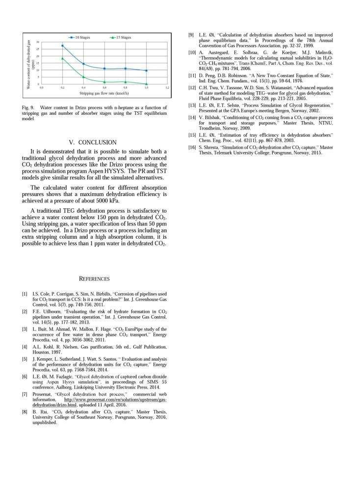
70 70

71 Appendix 3: Moisture prediction chart [McKetta - Wehe] 71
MODELLING OF REGENERATION IN TEG NATURAL GAS DEHYDRATION UNITS
 MODELLING OF REGENERATION IN TEG NATURAL GAS DEHYDRATION UNITS Aalborg University Esbjerg Oil and Gas Technology Master Thesis, Spring Semester 2017 MODELLING OF REGENERATION IN TEG NATURAL GAS DEHYDRATION
DISTILLATION POINTS TO REMEMBER
 DISTILLATION POINTS TO REMEMBER 1. Distillation columns carry out physical separation of liquid chemical components from a mixture by a. A combination of transfer of heat energy (to vaporize lighter components)
Optimizing Effective Absorption during Wet Natural Gas Dehydration by Tri Ethylene Glycol
 IOSR Journal of Applied Chemistry (IOSRJAC) ISSN : 2278-5736 Volume 2, Issue 2 (Sep-Oct. 212), PP 1-6 Optimizing Effective Absorption during Wet Natural Gas Dehydration by Tri Ethylene Glycol Khan, Mohd
Simulation and Economic Optimization of Vapor Recompression Configuration for Partial CO2 capture
 Simulation and Economic Optimization of Vapor Recompression Configuration for Partial CO2 capture Lars Erik Øi 1 Erik Sundbø 1 Hassan Ali 1 1 Department of and Process, Energy and Environmental Technology,
Journal of Chemical and Pharmaceutical Research, 2016, 8(5): Research Article
: Research Article") Available online www.jocpr.com Journal of Chemical and Pharmaceutical Research, 2016, 8(5):567-578 Research Article ISSN : 0975-7384 CODEN(USA) : JCPRC5 Investigation and Optimization of Gas Dehydration
Available online www.jocpr.com Journal of Chemical and Pharmaceutical Research, 2016, 8(5):567-578 Research Article ISSN : 0975-7384 CODEN(USA) : JCPRC5 Investigation and Optimization of Gas Dehydration
Removing nitrogen. Nitrogen rejection applications can be divided into two categories
 Removing nitrogen Doug MacKenzie, Ilie Cheta and Darryl Burns, Gas Liquids Engineering, Canada, present a comparative study of four nitrogen removal processes. Nitrogen rejection applications can be divided
PREPARING SOLUBILITY DATA FOR USE UPDATING KEY RESOURCES BY THE GAS PROCESSING INDUSTRY:
 PREPARING SOLUBILITY DATA FOR USE Mapping Midstream s Future 2012 GPA Convention BY THE GAS PROCESSING INDUSTRY: UPDATING KEY RESOURCES Darryl Mamrosh and Kevin Fisher Trimeric Corporation Jeff Matthews
Title: Choosing the right nitrogen rejection scheme
 Title: Choosing the right nitrogen rejection scheme Authors: Nicolas Chantant, Paul Terrien, Sylvain Gérard (Air Liquide Global E&C Solutions) Abstract: Nitrogen Rejection Units (NRU) are used to extract
FlashCO2, CO2 at 23 $/ton
 FlashCO2, CO2 at 23 $/ton A cost effective solution of capturing CO2 from Steam Methane Reforming (SMR) Hydrogen production plants by the FlashCO2 process Introduction to a cost effective solution Driven
DEHYDRATION OF ACID GAS PRIOR TO INJECTION Eugene W. Grynia, John J. Carroll, Peter J. Griffin, Gas Liquids Engineering, Calgary, Canada
 DEHYDRATION OF ACID GAS PRIOR TO INJECTION Eugene W. Grynia, John J. Carroll, Peter J. Griffin, Gas Liquids Engineering, Calgary, Canada Acid gas is a mixture of hydrogen sulfide and carbon dioxide, with
Figure Vapor-liquid equilibrium for a binary mixture. The dashed lines show the equilibrium compositions.
 Another way to view this problem is to say that the final volume contains V m 3 of alcohol at 5.93 kpa and 20 C V m 3 of air at 94.07 kpa and 20 C V m 3 of air plus alcohol at 100 kpa and 20 C Thus, the
Laser Spectrometers for Online Moisture Measurement in Natural Gas. Ken Soleyn GE M&C
 Laser Spectrometers for Online Moisture Measurement in Natural Gas Ken Soleyn GE M&C ken.soleyn@ge.com Introduction TDLAS (Tunable Diode Lase Absorption Spectroscopy) Moisture Analyzers have become the
A NEW PROCESS FOR IMPROVED LIQUEFACTION EFFICIENCY
 WHITE PAPER A NEW PROCESS FOR IMPROVED LIQUEFACTION EFFICIENCY Author(s): Adam Jones and Grant Johnson, Costain Natural Resources First published: GPAE, September 2014 www.costain.com A New Process for
PTRT 2470: Petroleum Data Management 3 - Facilities Test 4 (Spring 2017)
") Use scantron to answer all questions PTRT 2470: Petroleum Data Management 3 - Facilities Test 4 (Spring 2017) 1. The term dehydration of natural gas means A. addition of water vapor B. removal of water
Use scantron to answer all questions PTRT 2470: Petroleum Data Management 3 - Facilities Test 4 (Spring 2017) 1. The term dehydration of natural gas means A. addition of water vapor B. removal of water
Analysis and Modeling of Vapor Recompressive Distillation Using ASPEN-HYSYS
 Computer Science Journal of Moldova, vol.19, no.2(56), 2011 Analysis and Modeling of Vapor Recompressive Distillation Using ASPEN-HYSYS Cinthujaa C. Sivanantha, Gennaro J. Maffia Abstract HYSYS process
Training Fees 4,000 US$ per participant for Public Training includes Materials/Handouts, tea/coffee breaks, refreshments & Buffet Lunch.
 Training Title GAS CONDITIONING & PROCESSING Training Duration 5 days Training Venue and Dates Gas Conditioning & Processing 5 07 11 April, 2019 $4,000 Dubai, UAE Trainings will be conducted in any of
Thermodynamics ERT 206 Properties of Pure Substance HANNA ILYANI ZULHAIMI
 Thermodynamics ERT 206 Properties of Pure Substance HANNA ILYANI ZULHAIMI Outline: Pure Substance Phases of pure substance Phase change process of pure substance Saturation temperature and saturation pressure
PE096: Overview of Gas Processing Technology
 PE096: Overview of Gas Processing Technology PE096 Rev.001 CMCT COURSE OUTLINE Page 1 of 6 Training Description: This course is designed for a broad audience and is participative and interactive, utilizing
PURE SUBSTANCE. Nitrogen and gaseous air are pure substances.
 CLASS Third Units PURE SUBSTANCE Pure substance: A substance that has a fixed chemical composition throughout. Air is a mixture of several gases, but it is considered to be a pure substance. Nitrogen and
INTEROFFICE MEMORANDUM MODIFICATIONS TO DEW POINT CONTROL PROCESS
 INTEROFFICE MEMORANDUM TO: FROM: SUBJECT: NEW ENGINEER I.M. ANOLDGUY MODIFICATIONS TO DEW POINT CONTROL PROCESS DATE: JANUARY 10, 2017 We are looking to make modifications to our initial design for a DPC
Experimental Determination of Water Content of Sweet Natural Gas with Methane Component Below 70%
 International Journal of Scientific & Engineering Research Volume 8, Issue 7, July-2017 2324 Experimental Determination of Water Content of Sweet Natural Gas with Methane Component Below 70% Aimikhe, V.J;
Instructor s t Background
 Teknologi Pemrosesan Gas (TKK 564) Instructor: Dr. Istadi (http://tekim.undip.ac.id/staf/istadi ) Email: il iistadi@undip.ac.id di di id Instructor s t Background BEng. (1995): Universitas Diponegoro Meng.
LEAP CO 2 Laboratory CO 2 mixtures test facility
 LEAP CO 2 Laboratory CO 2 mixtures test facility THE PROJECT AIM CO 2 flows made available by several capture techniques are contaminated with impurities and this affects the design and operations of the
DISTILLATION PRESSURE CONTROL TROUBLESHOOTING THE HIDDEN PITTFALLS OF OVERDESIGN
 Distillation Absorption 2010 A.B. de Haan, H. Kooijman and A. Górak (Editors) All rights reserved by authors as per DA2010 copyright notice DISTILLATION PRESSURE CONTROL TROUBLESHOOTING THE HIDDEN PITTFALLS
0B Glycol Dehydration as a Mass Transfer Rate Process. Nathan A. Hatcher, Jaime L. Nava & Ralph H. Weiland Optimized Gas Treating, Inc.
 0B Glycol Dehydration as a Mass Transfer Rate Process Nathan A. Hatcher, Jaime L. Nava & Ralph H. Weiland Optimized Gas Treating, Inc. Sugar Land, TX ABSTRACT Glycol dehydration is a process that presents
 www.ompressedairsystems.com ultra-high purity nitrogen generators nitrogen purity: 95% to 99.999% www.ompressedairsystems.com ultra-high purity nitrogen generators nitrogen purity: 95% to 99.999% Leading
Experimental Analysis on Vortex Tube Refrigerator Using Different Conical Valve Angles
 International Journal of Engineering Research and Development e-issn: 7-067X, p-issn: 7-00X, www.ijerd.com Volume 3, Issue 4 (August ), PP. 33-39 Experimental Analysis on Vortex Tube Refrigerator Using
Dynamic Simulation and Control of Vapor Recompression Column
 The 7 th International Chemical Engineering Congress & Exhibition (IChEC 2011) Kish, Iran, 21-24 November, 2011 Dynamic Simulation and Control of Vapor Recompression Column Hojjat Dehghani, Mohammad Ali
Separation of Acetone-Water with Aspen HYSYS V8.0
 Separation of Acetone-Water with Aspen HYSYS V8.0 Liquid-Liquid Extraction with 3-Methylhexane as the Solvent 1. Lesson Objectives Learn how to build an extraction and solvent recovery flowsheet. Learn
Transient Analyses In Relief Systems
 Transient Analyses In Relief Systems Dirk Deboer, Brady Haneman and Quoc-Khanh Tran Kaiser Engineers Pty Ltd ABSTRACT Analyses of pressure relief systems are concerned with transient process disturbances
Finding leaks in Main Cryogenic Heat Exchangers without shutdown
 Finding leaks in Main Cryogenic Heat Exchangers without shutdown Liquefaction is the most fundamental step in the LNG production process. To achieve this there are several process solutions available,
THE INFLUENCE OF INCONDENSIBLE GASES ON THE REFRIGERATION CAPACITY OF THE RELIQUEFACTION PLANT DURING ETHYLENE CARRIAGE BY SEA
 Journal of KONES Powertrain and Transport, Vol. 23, No. 3 2016 THE INFLUENCE OF INCONDENSIBLE GASES ON THE REFRIGERATION CAPACITY OF THE RELIQUEFACTION PLANT DURING ETHYLENE CARRIAGE BY SEA Dariusz Nanowski
Nitrogen subtraction on reported CO 2 emission using ultrasonic flare gas meter
 Nitrogen subtraction on reported CO 2 emission using ultrasonic flare gas meter Kjell-Eivind Frøysa, Christian Michelsen Research AS, Bergen, Norway Henning Ekerhovd, StatoilHydro ASA, Kollsnes, Norway
COPYRIGHT. Reservoir Fluid Core. Single Phase, Single Component Systems. By the end of this lesson, you will be able to:
 Single Phase, Single Component Systems Learning Objectives Reservoir Fluid Core Single Phase, Single Component Systems By the end of this lesson, you will be able to: Define terms used to describe the
Gas Conditioning & Processing
 An Intensive 5 Day Training Course Gas Conditioning & Processing 09-13 Sep 2018, Dubai 20-NOV-17 This course is Designed, Developed, and will be Delivered under iso Quality standards Gas Conditioning &
High Efficiency SO2 Scrubber Design to Reduce Caustic Consumption
 High Efficiency SO2 Scrubber Design to Reduce Caustic Consumption Paper # 35 Andrew C. Bartocci Envitech, Inc. 2924 Emerson Street- Suite 320 San Diego, CA 92106 Ph: 619-223-9925, ext. 203 ABSTRACT An
Overview. OPIPOH10 - SQA Unit Code HG Operate an Oil and Gas Process ( Gas Treatment)
") OPIPOH10 - SQA Unit Code HG21 04 Overview This process involves the removal of impurities from the gas stream to reach the specified quality. The process boundary is from the inlet such as separator, compressor
OPIPOH10 - SQA Unit Code HG21 04 Overview This process involves the removal of impurities from the gas stream to reach the specified quality. The process boundary is from the inlet such as separator, compressor
On-Stream Tightness Testing of Vacuum Process Installations
 ECNDT 2006 - Tu.2.6.3 On-Stream Tightness Testing of Vacuum Process Installations André de JONGE, Leak Detection Group, DCI Meettechniek B.V., Kapelle, The Netherlands DCI Meettechniek. -DCI was founded
Natural Gas Desulfurization Process By MEA Amine: The preferable Engineering Design Procedure
 Natural Gas Desulfurization Process By MEA Amine: The preferable Engineering Design Procedure Ribwar Abdulrahman 1, Ibtisam Kamal 2, Jagar Ali 3 1 Faculty of Engineering, KoyaUniversity, Kurdistan region,
Instructor: Dr. Istadi (http://tekim.undip.ac.id/staf/istadi )
") Instructor: Dr. Istadi (http://tekim.undip.ac.id/staf/istadi ) Email: istadi@undip.ac.id Course Syllabus: (Part 1) 1. Definitions of Natural Gas, Gas Reservoir, Gas Drilling and Gas production (Pengertian
Instructor: Dr. Istadi (http://tekim.undip.ac.id/staf/istadi ) Email: istadi@undip.ac.id Course Syllabus: (Part 1) 1. Definitions of Natural Gas, Gas Reservoir, Gas Drilling and Gas production (Pengertian
NITROGEN GENERATION FOR INDUSTRIAL APPLICATIONS
 TRIDENT NOTES: NUMBER 5 DECEMBER 2017 NITROGEN GENERATION FOR INDUSTRIAL APPLICATIONS Industry requires nitrogen Dozens of gases are used by industry. First among these in terms of quantity consumed is
Inprocess Operator Training Programme
 2016 Inprocess Operator Training Programme ABSORPTION COLUMN These exercises are intended to provide an understanding of absorption columns and the fundamental principles they use to eliminate pollutants
ON-SITE INDUSTRIAL GASES. Nitrogen & Oxygen Generators
 ON-SITE INDUSTRIAL GASES Nitrogen & Oxygen Generators A SECURE SUPPLY OF NITROGEN AND OXYGEN Whether your company is specialized in chemical manufacturing, electronics, laser cutting or food and beverage,
Vapor Recovery from Condensate Storage Tanks Using Gas Ejector Technology Palash K. Saha 1 and Mahbubur Rahman 2
 37 Journal of Chemical Engineering, IEB Vapor Recovery from Condensate Storage Tanks Using Gas Ejector Technology Palash K. Saha 1 and Mahbubur Rahman 2 Abstract 1 Bibyana Gas Field 2 Department of Petroleum
GLOSSARY OF TERMS. Adiabatic Compression Compression process when all heat of compression is retained in the gas being compressed.
 GLOSSARY OF TERMS Absolute pressure Total pressure measured from absolute zero i.e. a perfect vacuum. As a practical matter, gauge pressure plus atmospheric pressure. Absolute temperature Temperature measured
Membrane modules for nitrogen and oxygen generator systems. Technology Overview ENGINEERING YOUR SUCCESS.
 Membrane modules for nitrogen and oxygen generator systems Technology Overview ENGINEERING YOUR SUCCESS. Parker modules the heart of OEM tailor-made nitrogen generators OEM (Original Equipment Manufacturer)
SUPERSONIC GAS TECHNOLOGIES
 SUPERSONIC GAS TECHNOLOGIES Vladimir Feygin, Salavat Imayev, Vadim Alfyorov, Lev Bagirov, Leonard Dmitriev, John Lacey TransLang Technologies Ltd., Calgary, Canada 1. INTRODUCTION The 3S technology is
Simulation of Gas Dehydration Plants Safe Operation in Chemical Industry
 Simulation of Gas Dehydration Plants Safe Operation in Chemical Industry GABRIELA BUCUR, ADRIAN GEORGE MOISE*, CRISTINA POPESCU Petroleum Gas University of Ploiesti, 39 Bucuresti Blvd., 100680, Ploiesti,
OIL AND GAS PROCESSES AND EMISSIONS
 OIL AND GAS PROCESSES AND EMISSIONS This document provides a brief description of oil and gas activities, equipment and expected pollutants from those equipment types. The emissions processes are discussed
Focus on VOC Emissions Reduction Using an Oxygen Based Inerting Control System For Inert Gas Blanketing of Chemical Process Vessels
 Inerting Control Systems by NTRON PROCESS ANALYZER DIVISION of NEUTRONICS INC. EXTON. PA. 19341 RJN Rev. A June 2001 Focus on VOC Emissions Reduction Using an Oxygen Based Inerting Control System For Inert
Gas Vapor Injection on Refrigerant Cycle Using Piston Technology
 Purdue University Purdue e-pubs International Refrigeration and Air Conditioning Conference School of Mechanical Engineering 2012 Gas Vapor Injection on Refrigerant Cycle Using Piston Technology Sophie
maintaining storage tank dissolved oxygen levels utilizing gas transfer membranes
 Water Technologies & Solutions technical paper maintaining storage tank dissolved oxygen levels utilizing gas transfer membranes Authors: W.E. Haas, SUEZ, J. Helmrich, Florida Power and Light and J.E.
CALCULATING THE SPEED OF SOUND IN NATURAL GAS USING AGA REPORT NO Walnut Lake Rd th Street Houston TX Garner, IA 50438
 CALCULATING THE SPEED OF SOUND IN NATURAL GAS USING AGA REPORT NO. 10 Jerry Paul Smith Joel Clancy JPS Measurement Consultants, Inc Colorado Engineering Experiment Station, Inc (CEESI) 13002 Walnut Lake
Experiment 18 Properties of Gases
 Experiment 18 Properties of Gases E18-1 E18-2 The Task In this experiment you will investigate some of the properties of gases, i.e. how gases flow, their phase changes and chemical reactivity. Skills
Ball Beating Lubrication in Refrigetation Compressors
 Purdue University Purdue e-pubs International Compressor Engineering Conference School of Mechanical Engineering 1996 Ball Beating Lubrication in Refrigetation Compressors B. Jacobson SKF Engineering &
HOW TO MANAGE VAPORIZATION IN AN ANALYTICAL SYSTEM By Dean Slejko and Tony Waters
 HOW TO MANAGE VAPORIZATION IN AN ANALYTICAL SYSTEM By Dean Slejko and Tony Waters If the analyzer in your analytical system requires gas but your sample is liquid, the only option is to convert the liquid
DISTILLATION COLUMN PROCESS CONTROL STRATEGIES
 DISTILLATION COLUMN PROCESS CONTROL STRATEGIES Satyajit Deshmukh 1, Salil Rajwade 2, Atharva Pundalik 3, Anil Ranveer 4 ABSTRACT 1,2,3,4 Chemical Engineering Department, Datta Meghe College of Engineering,
You should be able to: Describe Equipment Barometer Manometer. 5.1 Pressure Read and outline 5.1 Define Barometer
 A P CHEMISTRY - Unit 5: Gases Unit 5: Gases Gases are distinguished from other forms of matter, not only by their power of indefinite expansion so as to fill any vessel, however large, and by the great
Liquid Ring Compressor Catching Chemicals Conserving Cash
 Liquid Ring Compressor Catching Chemicals Conserving Cash You favour inherently safer solutions avoiding hazards rather than controlling them. We have developed a new range of compressors. 1 NSB GAS PROCESSING
Potter Nitrogen Generators
 Potter Nitrogen Generators What is nitrogen? Nitrogen the inert gas Earth s atmosphere the air we breathe is composed of nitrogen, oxygen, and water vapor. While this atmosphere is great for life, it is
From the Choke KO drum, the gas passes through another gas/gas exchanger - the 'LTS Pre-cooler'.
 Refer to Figures: 16 & 17 as you read on. Wet, natural gas direct from the wellstreams, at about 1600 Psi, is first pre-cooled and separated from liquids in an 'Intermediate Separator' and cooled in a
Fit for Purpose Compositional Input for Allocation Using Equations of State Thomas Hurstell, Letton Hall Group
 UPM 15030 Fit for Purpose al Input for Allocation Using Equations of State Thomas Hurstell, Letton Hall Group Abstract Methods are presented to develop compositional input for use in allocation systems
Kolmetz Handbook Of Process Equipment Design AMINE GAS DEHYDRATION SYSTEM SIZING AND SELECTION (ENGINEERING DESIGN GUIDELINE)
") Page : 1 of 99 Processing Plant KLM Technology #03-12 Block Aronia, Jalan Sri Perkasa 2 Taman Tampoi Utama 81200 Johor Bahru Malaysia www.klmtechgroup.com, Standards, Software AMINE GAS DEHYDRATION SYSTEM
Page : 1 of 99 Processing Plant KLM Technology #03-12 Block Aronia, Jalan Sri Perkasa 2 Taman Tampoi Utama 81200 Johor Bahru Malaysia www.klmtechgroup.com, Standards, Software AMINE GAS DEHYDRATION SYSTEM
ERTC PETROCHEMICAL Conference 20 st -22 nd February 2002, Amsterdam, The Netherlands
 Reprint from Presentation at ERTC PETROCHEMICAL Conference 20 st -22 nd February 2002, Amsterdam, The Netherlands and ARTC PETROCHEMICAL Conference 11 th 13 th March 2002, Bangkok, Thailand Sulzer Chemtech,
Applied Compression s nitrogen generator packages offer users a cost-effective alternative to costly bottled nitrogen.
 APPLICATIONS: Autoclaves Modified Packaging Atmospheres Coffee Packaging Oxidation Control Coil Tubing Units Pharmaceutical Manufacturing Electronic Parts Manufacturing Reflow Ovens Enhanced Oil Recovery
CHE 306 Stagewise Operations
 CHE 306 Stagewise Operations Fall 2010 Introduction ti to Column Distillation Instructor: Dr. Housam Binous KFUPM, Dhahran 1 Over 90% of separations are done using distillation Over 40 000 distillation
Treatment plants for gas production
 5.4 Treatment plants for gas production 5.4.1 Introduction This chapter examines the treatments required for the transport and distribution of natural gas. It will discuss the main processes used to purify
Vortex flowmeters. Product family introduction Principle of operation Product review Applications Key product features
 Vortex flowmeters introduction Product review s Key product features This document should not be duplicated, used, distributed, or disclosed for any purpose unless authorized by Siemens. Page 1 Vortex
Micro Channel Recuperator for a Reverse Brayton Cycle Cryocooler
 Micro Channel Recuperator for a Reverse Brayton Cycle Cryocooler C. Becnel, J. Lagrone, and K. Kelly Mezzo Technologies Baton Rouge, LA USA 70806 ABSTRACT The Missile Defense Agency has supported a research
Improving distillation tower operation
 Improving distillation tower operation Measuring differential pressure across long sections of distillation columns has always been challenging, but purpose-built sensor systems provide a solution Fast
Fundamentals Of Petroleum Engineering PRODUCTION
 Fundamentals Of Petroleum Engineering PRODUCTION Mohd Fauzi Hamid Wan Rosli Wan Sulaiman Department of Petroleum Engineering Faculty of Petroleum & Renewable Engineering Universiti Technologi Malaysia
CLOSED LOOP SOLVENT EMISSIONS CONTROL. David C.H. Grant
 CLOSED LOOP SOLVENT EMISSIONS CONTROL David C.H. Grant Abstract: An approach to closed loop solvent emissions control systems, useful for all conventional solvent processes and solvents is presented. The
44 (0) E:
 E:") FluidFlow Relief Valve Sizing Handbook Flite Software 2016 Flite Software N.I. Ltd, Block E, Balliniska Business Park, Springtown Rd, Derry, BT48 0LY, N. Ireland. T: 44 (0) 2871 279227 E: sales@fluidflowinfo.com
FluidFlow Relief Valve Sizing Handbook Flite Software 2016 Flite Software N.I. Ltd, Block E, Balliniska Business Park, Springtown Rd, Derry, BT48 0LY, N. Ireland. T: 44 (0) 2871 279227 E: sales@fluidflowinfo.com
Column Design Using Mass Transfer Rate Simulation
 Column Design Using Mass Transfer Rate Simulation by Ralph H. Weiland and John C. Dingman Optimized Gas Treating, Inc, 15638 Whitewater Lane Houston, TX 77079, U.S.A. info@ogtrt.com Presented at the 80
Earlier Lecture. In the earlier lecture, we have seen Kapitza & Heylandt systems which are the modifications of the Claude System.
 17 1 Earlier Lecture In the earlier lecture, we have seen Kapitza & Heylandt systems which are the modifications of the Claude System. Collins system is an extension of the Claude system to reach lower
Drilling Efficiency Utilizing Coriolis Flow Technology
 Session 12: Drilling Efficiency Utilizing Coriolis Flow Technology Clement Cabanayan Emerson Process Management Abstract Continuous, accurate and reliable measurement of drilling fluid volumes and densities
EXAM # 2. First Name Last Name CIRCLE YOUR LECTURE BELOW: INSTRUCTIONS
 CIRCLE YOUR LECTURE BELOW: First Name Last Name Div. 1 08:30 am Prof. Chen Div. 2 11:30 am Prof. Braun EXAM # 2 INSTRUCTIONS 1. This is a closed book examination. You are allowed to have two single sheets
Chem 110 General Principles of Chemistry
 CHEM110 Worksheet - Gases Chem 110 General Principles of Chemistry Chapter 9 Gases (pages 337-373) In this chapter we - first contrast gases with liquids and solids and then discuss gas pressure. - review
THERMODYNAMICS OF A GAS PHASE REACTION: DISSOCIATION OF N 2 O 4
 THERMODYNAMICS OF A GAS PHASE REACTION: DISSOCIATION OF N 2 O 4 OBJECTIVES 1. To measure the equilibrium constant, enthalpy, entropy, and Gibbs free energy change of the reaction N2O4(g) = 2 NO2(g). 2.
Atlas Copco. On-site Industrial Gases Nitrogen & Oxygen Generators
 Atlas Copco On-site Industrial Gases Nitrogen & Oxygen Generators A secure supply of nitrogen and oxygen Whether your company is specialized in chemical manufacturing, electronics, laser cutting or food
Another convenient term is gauge pressure, which is a pressure measured above barometric pressure.
 VACUUM Theory and Applications Vacuum may be defined as the complete emptiness of a given volume. It is impossible to obtain a perfect vacuum, but it is possible to obtain a level of vacuum, defined as
SAFETY MANUAL FOR FLAMMABLE PRODUCT TRANSFER
 SAFETY MANUAL FOR FLAMMABLE PRODUCT TRANSFER SUPPLIMENT TO eom IMPORTANT READ THIS MANUAL BEFORE PRODUCT INSTALLATION, OPERATION, INSPECTION & MAINTENANCE Tougher and more rigid guidelines are being established
--- III. itti A. on_ coo. & EP Department DOCUMENT NO: WOC-HSE-ST Section H005 Hydrates
 --- III itti A. on_ coo WOC LP & EP Department WOC HSE Standards Manual DOCUMENT NO: WOC-HSE-ST-0001 Section H005 Hydrates REV ISSUE PREPARED BY REVIEWED BY APPROVED BY ISSUE DATE 044 /- 6 WO Executive
Procedure of Xenon Transfer
 Procedure of Xenon Transfer Feng Zhou,MIT CC: Martina Green February 28, 2005 In this write up, we discuss the procedure on how to transfer xenon to a designed gas storage vessel that supplies xenon to
Under pressure pushing down
 Under pressure pushing down on me When Dalton was conducting his studies, which led him to the atomic-molecular theory of matter, he also included studies of the behaviour of gases. These led him to propose,
International Journal of Petroleum and Geoscience Engineering Volume 03, Issue 01, Pages 56-60, 2015
 International Journal of Petroleum and Geoscience Engineering Volume 03, Issue 01, Pages ISSN: 2289-4713 Investigation of Under-Saturated Oil Viscosity Correlations under Reservoir Condition; A Case Study
1 PIPESYS Application
 PIPESYS Application 1-1 1 PIPESYS Application 1.1 Gas Condensate Gathering System In this PIPESYS Application, the performance of a small gascondensate gathering system is modelled. Figure 1.1 shows the
MODEL PREDICTIVE CONTROL OF INTEGRATED UNIT OPERATIONS CONTROL OF A DIVIDED WALL COLUMN
 MODEL PREDICTIVE CONTROL OF INTEGRATED UNIT OPERATIONS CONTROL OF A DIVIDED WALL COLUMN Prof. Dr. Till Adrian*, Dr. Hartmut Schoenmakers**, Dr. Marco Boll** * Mannheim University of Applied Science, Department
AirSep PSA Nitrogen Systems
 AirSep PSA Nitrogen Systems For Commercial Applications AirSep Corporation An Organization with a Global Presence Quality and long-term value are built into every AirSep product for total customer satisfaction.
THE GUIDE TO MEMBRANE NITROGEN GENERATORS
 THE GUIDE TO MEMBRANE NITROGEN GENERATORS MEMBRANE NITROGEN GENERATORS The membrane nitrogen generator utilizes a hollow porous fiber to separate the N 2 molecules from other molecules, including O 2.
Outcomes: Operationally define vapour pressure
 Vapour Pressure Outcomes: Operationally define vapour pressure Vapour Pressure: Recall that in order for a liquid to VAPORIZE, it must overcome the FORCE of the ATMOSPHERIC PRESSURE. Vapour Pressure (P
PETROLEUM & GAS PROCESSING TECHNOLOGY (PTT 365) SEPARATION OF PRODUCED FLUID
 SEPARATION OF PRODUCED FLUID") PETROLEUM & GAS PROCESSING TECHNOLOGY (PTT 365) SEPARATION OF PRODUCED FLUID Miss Nur Izzati Bte Iberahim Introduction Well effluents flowing from producing wells come out in two phases: vapor and liquid
PETROLEUM & GAS PROCESSING TECHNOLOGY (PTT 365) SEPARATION OF PRODUCED FLUID Miss Nur Izzati Bte Iberahim Introduction Well effluents flowing from producing wells come out in two phases: vapor and liquid
M-06 Nitrogen Generator (Nitrogen Making Machine)
") Guideline No.M-06 (201510) M-06 Nitrogen Generator (Nitrogen Making Machine) Issued date: 20 th October, 2015 China Classification Society Foreword This Guideline is a part of CCS Rules, which contains
Guideline No.M-06 (201510) M-06 Nitrogen Generator (Nitrogen Making Machine) Issued date: 20 th October, 2015 China Classification Society Foreword This Guideline is a part of CCS Rules, which contains
Distillation Design The McCabe-Thiele Method
 Distillation Design The McCabe-Thiele Method Distiller diagam Introduction Using rigorous tray-by-tray calculations l is time consuming, and is often unnecessary. One quick method of estimation i for number
Steam generator tube rupture analysis using dynamic simulation
 Steam generator tube rupture analysis using dynamic simulation Heat Exchangers are used to transfer heat from a hot fluid to a cold fluid. Most of the times these fluids are available at different pressures
Generating Calibration Gas Standards
 Technical Note 1001 Metronics Inc. Generating Calibration Gas Standards with Dynacal Permeation Devices Permeation devices provide an excellent method of producing known gas concentrations in the PPM and
METHODS TO PREVENT THE PREMATURE ACTIVATION OF RELIEF DEVICES ON TRANSPORT TANKS
 METHODS TO PREVENT THE PREMATURE ACTIVATION OF RELIEF DEVICES ON TRANSPORT TANKS IGC Doc 184/14/E EUROPEAN INDUSTRIAL GASES ASSOCIATION AISBL AVENUE DES ARTS 3-5 B 1210 BRUSSELS Tel: +32 2 217 70 98 Fax:
GAS DEHYDRATION SYSTEM
 GAS DEHYDRATION SYSTEM High pressure gases from the Gas Compressors (CBA-4070/4020) flow to the Glycol Contactor (MAF-1150). In the Contactor, gas flows through trays, contacting the lean glycol that is
Technical Information
 Technical Information Installation, Operation, Installation, Operation and Maintenance and Maintenance Manual Manual Balston Model 75700-K728 Nitrogen Generator Figure 1-75700-K728 Overall Dimensions These
Laboratory Hardware. Custom Gas Chromatography Solutions WASSON - ECE INSTRUMENTATION. Custom solutions for your analytical needs.
 Laboratory Hardware Custom Gas Chromatography Solutions Custom solutions for your analytical needs. Laboratory Hardware Wasson-ECE Instrumentation offers hardware-only solutions for advanced chromatography