Relief Systems. 11/6/ Fall
|
|
|
- Lindsay McKenzie
- 5 years ago
- Views:
Transcription
1 Relief Systems 1
2 Relief Scenarios o A single relief event requires a particulate vent area and valve size o Relief scenarios are determined based on a PHA o For each scenario, a vent area is calculated o The worst-case scenario requires the largest vent area. o Ex. Relief scenarios: Ex. 8-2, p. 363, Tab 8-2, p
3 A rupture conventional disc to protect relief valve PSV-lb from the reactive monomers (plugging from polymerization a relief valve for liquid balanced service bellows only conventional relief valve 3
4 Ex 8-2 Relief Scenarios Relief Identifications PSV-1a & PSV-1b PSV-2 PSV-3 PSV-4 PSV-5 Scenarios Vessel full of l and P-1 is accidentally actuated Cooling coil is broken and water enters at 200gpm and 50 psig N 2 regulator fails, giving critical flow in 1 line Runaway rxn (Loss of cooling) V1 is accidentally closed; systems need relief for 100 gpm at 50 psig Confined water line is heated with 125-psig steam N 2 regulator fails, giving critical flow in 1/2 line The other R-1 scenario will be relieved via PSV-1 Water blocked inside coil, and heat of rxn causes thermal expansion 4
5 Data for Relief Sizing o Physical property data o Chemical reaction rate behavior o Single phase releases: vapor, liquid, solid o Multiple phase releases o Runaway reaction relief: liquid & vapor o Gas or dust explosions from combustion apparatus o These data are part of the process safety information needed for a PHA 5
6 Reaction Behavior Measurement o For accurate relief vent area determinations, experimental data are most important o Calorimeters are used to characterize behavior during normal reaction or runaway. o Sample is progressively heated to search for an exothermic reaction o Raw data includes T, P, time, amount of non condensable gas formed, onset temperature, maximum heat rate, maximum pressure rate 6
7 Runaway reaction temperature data acquired using the vent sizing package (VSP) 7
8 Runaway reaction pressure data acquired using the vent sizing package 8
9 Runaway Reaction Behavior Runaway Region Rate of Heat Production Heat Removal Q r Q g > Q r Q g Heat Generated Temperature A 9
10 Preventing a Runaway Reaction o Measures to prevent a polymerization reaction runaway due to loss of coolant: o Coolant flow gauge with low-flow alarm o Stirrer rpm gauge with alarm o Stirrer and coolant interlock for monomer addition (inherent safety principle) o Monomer addition stopped if coolant control valve near 100 % open. o Temperature sensors along length of reactor to check for normal profile and upset indication 10
11 Relief Installation Guidelines o Industrial standards published by the American Society of Mechanical Engineers (ASME) and by the American Petroleum Institute (API) - Stress analysis and reaction forces for material flow through relief systems: API standards - Relief system weight - Static pressure, pressure changes 11
12 Relief Installation Examples o Two rupture disks with pressure gauge between to detect for leakage: toxic materials o Two rupture disks connected with 3-way valve to allow maintenance on one disk o Backup rupture disk in parallel with a smaller relief valve set at a lower pressure. o Rupture disk to protect more expensive relief valve with a pressure gauge between them 12
13 Location Guidelines o Relief valves on all vessels o Pressure or vacuum protection for vessels o Steam jackets o Pipes between valves o Pumps, compressors, turbines on discharge o High pressure connected to low pressure o Safety/cost balance: relief device vs design for highest pressure 13
14 14
15 15
16 16
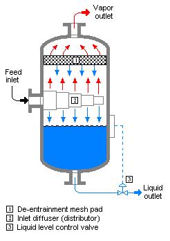
17 Total Containment Systems o Relief materials are mostly vented to total containment and treatment systems o Knockout: separation of liquid from vapor; coolant for high boiling material (Ex 8-3, p. 374) o Liquid collected, transferred, incinerated o Vapor transferred to treatment, e.g., condenser (high boiling), scrubber (toxic), incinerator, flare (combustible, toxic), combination 17
18 18
19 Relief containment system with blowdown drum. The blowdown drum separates the vapor from the liquid 19
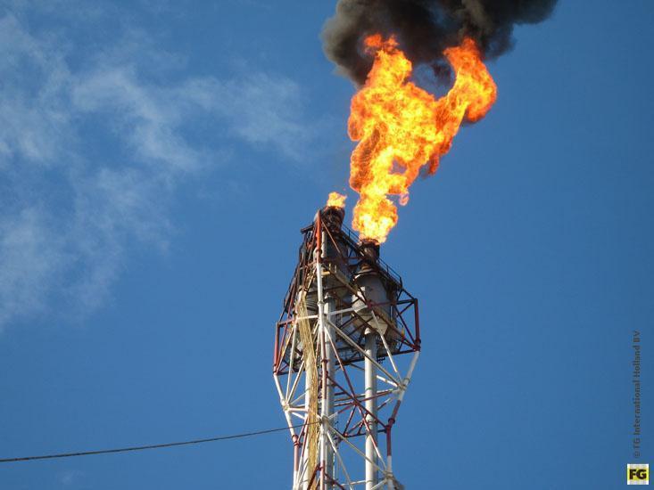
20 Material Treatment o Flares: flammable or toxic materials converted to less hazardous combustion products - Flare design: for a stable flame and a nonhazardous radiation (Ex 8-4, p. 375) o Scrubbers: columns for surface contact; convert to less hazardous or more manageable materials - Scrubber examples: caustic bath (H 2 S), water (NO 2 ) 20
21 21
22 22
APPENDIX WORKED EXAMPLES
 Sufe Design and Optvation ofpi-oc.ess Vents and Emission Contid $wteins by Center for Chemical Process Safety Copyright 0 2006 John Wiley & Sons, Tnc. APPENDIX G WORKED EXAMPLES This appendix provides
6.6 Relief Devices. Introduction
 6.6 Relief Devices Introduction Relief devices are used to help prevent a catastrophic failure of equipment and/or minimize the effects of any unanticipated or uncontrolled events. As such, relief devices
General Duty Clause. Section 112(r)(1) of CAA. Chris Rascher, EPA Region 1
(1) of CAA. Chris Rascher, EPA Region 1") General Duty Clause Section 112(r)(1) of CAA Chris Rascher, EPA Region 1 Background on the General Duty Clause General Duty Clause 112(r)(1) of CAA Prevention of Accidental Releases Purpose and General
General Duty Clause Section 112(r)(1) of CAA Chris Rascher, EPA Region 1 Background on the General Duty Clause General Duty Clause 112(r)(1) of CAA Prevention of Accidental Releases Purpose and General
Relief System Sizing for Runaway Chemical Reactions: A Simple Comprehensive Approach
 Relief System Sizing for Runaway Chemical Reactions: A Simple Comprehensive Approach Ken Kurko Fauske & Associates, LLC 16W070 83 rd Street Burr Ridge, IL 60527 kurko@fauske.com Prepared for Presentation
Absorption - The process of contacting a vapor and gas stream with an absorbing liquid to remove specific materials from the gas stream.
 Sufe Design and Optvation ofpi-oc.ess Vents and Emission Contid $wteins by Center for Chemical Process Safety Copyright 0 2006 John Wiley & Sons, Tnc. APPENDIX B GLOSSARY Absorption - The process of contacting
Steam generator tube rupture analysis using dynamic simulation
 Steam generator tube rupture analysis using dynamic simulation Heat Exchangers are used to transfer heat from a hot fluid to a cold fluid. Most of the times these fluids are available at different pressures
Challenges in Relief Design for Pilot Plants
 Challenges in Relief Design for Pilot Plants Published on July 5, 2017 Michael Trainor Relief system design at the pilot scale presents unique challenges that don t always apply at the commercial scale.
COMMITTEE DRAFT. API 520 Part I 10 th Edition Ballot Item 2.1. This ballot covers the following item:
 This ballot covers the following item: API 520 Part I 10 th Edition Ballot Item 2.1 2008 12 Modify guidance to PRV datasheets (Line 17) to assist user s with determining the temperature to use for selecting
PSK Standards Association PSK 4917 Appendix 14
 PSK Standards Association PSK 4917 Appendix 14 1 (6) Manufacturer: Yritys Oy RESULTS OF ANALYSIS ACCORDING TO DIRECTIVE 97/23/EY (PED) Address: Purchaser: Tilaaja Oy Document identification: 127860178623-
SAFETY MANUAL PURGING, VENTING & DRAINING PROCEDURE TABLE OF CONTENTS 1. INTRODUCTION SCOPE DEFINITIONS PROCEDURE...
 Page 1 of 11 TABLE OF CONTENTS 1. INTRODUCTION... 2 2. SCOPE... 2 3. DEFINITIONS... 2 4.... 3 5. RESPONSIBILTIES... 10 6. REFERENCES... 10 7. ATTACHMENTS... 11 8. APPENDICES... 11 Rev. Issue Date Amendment
PRESSURE RELIEF VENTING SYSTEMS EXAMPLES OF GOOD AND BAD PRACTICE
 PRESSURE RELIEF VENTING SYSTEMS EXAMPLES OF GOOD AND BAD PRACTICE John Hare and Michael Johnson, Health and Safety Laboratory, Buxton, UK Pressure relief systems employed at chemical and petrochemical
Tube rupture in a natural gas heater
 Tube rupture in a natural gas heater Dynamic simulation supports the use of a pressure safety valve over a rupture disk in the event of a tube rupture HARRY Z HA and PATRICK STANG Fluor Canada Ltd A fast
MSC Guidelines for Review of Vapor Control Systems Procedure Number: C1-46 Revision Date: 01/08/2018
 T. O. Phillips, CDR, Chief, Tank Vessel & Offshore Division Purpose: The purpose of this document is to provide guidance and information regarding the submission of vapor control system (VCS) piping plans
Title: Pressure Relieving and Venting Devices Function: Ecology & Safety No.: BC Page: 1 of 7 Reviewed: 6/30/12 Effective: 7/1/12 (Rev.
 Preparer: Team Member, North America, Process Safety Center of Expertise No.: BC032.020 Page: 1 of 7 Owner: Manager, North America Process Safety Center of Expertise Approver: Sr. Vice President, Ecology
FLUID DYNAMICS Ch.E-204 Umair Aslam Lecturer Department of Chemical Engineering
 FLUID DYNAMICS Ch.E-204 Umair Aslam Lecturer Department of Chemical Engineering Fluid Mechanics is the branch of physics that studies fluids (liquids, gases, and plasmas) and the forces on them. Fluid
Minimum standard of competence in advanced training for liquefied gas tanker cargo operations (STCW Reg V/1-2)
") Minimum standard of in advanced training for liquefied gas tanker cargo operations (STCW Reg V/1-2) Column 2 Knowledge, understanding and proficiency Design and characteristics of a liquefied gas tanker
Minimum standard of in advanced training for liquefied gas tanker cargo operations (STCW Reg V/1-2) Column 2 Knowledge, understanding and proficiency Design and characteristics of a liquefied gas tanker
Before You Fix the Relief Valve Problem
 Before You Fix the Relief Valve Problem Careful considerations when mitigating inadequate relief systems designs Jason Spearow, P.E Presenter Biography Jason Spearow, P.E. Smith & Burgess LLC Senior Process
Frequently Asked Questions Directive 056 Facilities Technical
 Frequently Asked Questions Directive 056 Facilities Technical October 2017 This document clarifies and supports some of the technical requirements related to Directive 056: Energy Development Applications
COMPONENT AVAILABILITY EFFECTS FOR PRESSURE RELIEF VALVES USED AT HYDROGEN FUELING STATIONS
 COMPONENT AVAILABILITY EFFECTS FOR PRESSURE RELIEF VALVES USED AT HYDROGEN FUELING STATIONS Moussin Daboya-Toure, M.D-T. 1, Robert Burgess, R.B. 2 and Aaron Harris, A.H. 3 1 Air Liquide Advanced Technologies,
MSC Guidelines for the Review of Vapor Control Systems Procedure Number: C1-46 Revision Date: March 30, 2012
 R. J. LECHNER, CDR, Tank Vessel and Offshore Division Purpose: To outline procedures for review of vapor control system (VCS) piping plans and pressure drop calculations, and for generating a VCS List
FAILURE AND HAZARD ANALYSIS OF THE NPDGAMMA LH2 TARGET SYSTEM
 FAILURE AND HAZARD ANALYSIS OF THE NPDGAMMA LH2 TARGET SYSTEM Revision: 0.00 Edited by: Seppo Penttila, November 10, 2010 1. General The RSS 8305.0 Installation, Commissioning, and Operation of the NPDGamma
VB-7212 Series. Application. Features. Applicable Literature. 5/8" O.D., 45 SAE Flared Stem Up Open, Two-Way Valves General Instructions
 VB-7212 Series 5/8" O.D., 45 SAE Flared Stem Up Open, Two-Way Valves General Instructions Application VB-7212 series single seat, stem up open, two-way valves control water from 20 to 281 F (-7 to 138
Identification and Screening of Scenarios for LOPA. Ken First Dow Chemical Company Midland, MI
 Identification and Screening of Scenarios for LOPA Ken First Dow Chemical Company Midland, MI 1 Layers of Protection Analysis (LOPA) LOPA is a semi-quantitative tool for analyzing and assessing risk. The
Pressure Piping Code-Industrial Piping. Part 6: Safeguarding
 ICS 23.040 J74 National Standard of the People's Republic of China GB/T 20801.6-2006 Pressure Piping Code-Industrial Piping Part 6: Safeguarding ffi1jtfil~ju1t1 I~tfil ~6$?t: ~~~1? Issued on: December
Reduce Turnaround Duration by Eliminating H 2 S from Flare Gas Utilizing VaporLock Scrubber Technology
 Reduce Turnaround Duration by Eliminating H 2 S from Flare Gas Utilizing VaporLock Scrubber Technology Jim Woodard Vice President of Sales Bryant Woods Lead Project Engineer 4/3/18 Page 1 Objectives Impact
Welcome to the LESER Seminar, Taipei 28. June Design_of_safety_relief_valves_250804_Cal
 Welcome to the LESER Seminar, Taipei 28. June 2006 1 Design of safety relief valves 2 Design of safety valves Target Classification of Pressure Relief Devices General design of Safety Relief valves 3 Design
ANNEX AMENDMENTS TO THE INTERNATIONAL CODE FOR FIRE SAFETY SYSTEMS (FSS CODE) CHAPTER 15 INERT GAS SYSTEMS
 CHAPTER 15 INERT GAS SYSTEMS") Annex 3, page 2 ANNEX AMENDMENTS TO THE INTERNATIONAL CODE FOR FIRE SAFETY SYSTEMS (FSS CODE) CHAPTER 15 INERT GAS SYSTEMS The text of existing chapter 15 is replaced by the following: "1 Application This
Annex 3, page 2 ANNEX AMENDMENTS TO THE INTERNATIONAL CODE FOR FIRE SAFETY SYSTEMS (FSS CODE) CHAPTER 15 INERT GAS SYSTEMS The text of existing chapter 15 is replaced by the following: "1 Application This
CPE562 Chemical Process Control HOMEWORK #1 PROCESS & INSTRUMENTATION DIAGRAM
 Faculty of Chemical Engineering CPE562 Chemical Process Control HOMEWORK #1 PROCESS & INSTRUMENTATION DIAGRAM SUBMISSION DATE: 1 OCT. 2012 Question 1 Name the following equipments based on standard P&ID
The Relationship Between Automation Complexity and Operator Error
 The Relationship Between Automation Complexity and Operator Error presented by Russell Ogle, Ph.D., P.E., CSP rogle@exponent.com (630) 274-3215 Chemical Plant Control Control physical and chemical processes
Permitted MSS Emissions Tracking, Recordkeeping, and Reporting. Presented by ACES April 24, 2008
 Permitted MSS Emissions Tracking, Recordkeeping, and Reporting Presented by ACES April 24, 2008 1 Agenda Introductions Overview of Current MSS Permitting Program Status Discussion of Model MSS Permit Requirements
PRESSURE RELIEF DEVICES. Table of Contents
 FM Global Property Loss Prevention Data Sheets 12-43 October 2013 Page 1 of 13 PRESSURE RELIEF DEVICES Table of Contents Page 1.0 SCOPE... 2 1.1 Changes... 2 1.2 Superseded Information... 2 2.0 LOSS PREVENTION
Steam System Best Practices 14 Best Practices for Guide Lines for Boiler Plant Log Books
 Steam System Best Practices 14 Best Practices for Guide Lines for Boiler Plant Log Books 1. SCOPE OF BOILER LOGBOOK PROGRAM In all cases, there are minimum tasks and functions for an operator to perform
Changes Between API STD 520 Part II 6th Ed and 5th Ed Cataloged
 Changes Between API STD 520 Part II 6th Ed and 5th Ed Cataloged Dustin Smith Smith & Burgess LLC 7600 W Tidwell, Houston, TX Dustin.Smith@smithburgess.com John Burgess Jessye Palladino Smith & Burgess
Operating Instructions
 Operating Instructions Before operating the thin film evaporator, please be aware of all safety concerns associated with this experiment: Burn hazard from the column and steam lines, Chemical hazards associated
SERIES 30. Spring Operated Tank Blanketing Valve PROTECTOSEAL.
 SERIES 30 PROTECTOSEAL 1 2" NPT inlet and outlet standard Direct acting valve mechanism Optional flanged or threaded inlet and outlet connections available Inlet gas pressures from 10 PSIG to 200 PSIG
EASTERN ENERGY SERVICES PTE LTD. 60 Kaki Bukit Place #02-19 Eunos Tech Park Singapore, SG Singapore Telephone: Fax:
 2 Table Of Contents 1. Introduction 3 2. About this Manual 3 3. Contacting YZ Systems 3 4. Vessel Components 4 5. Specifications 5 6. Application 6 7. Theory of Operation 7 8. DuraSite Installation & Use
3 rd Year Design Module Scope
 LOSS PREVENTION & Process Safety PROCESS HAZARDS ANALYSIS -3 rd Year Design Module - 3 rd Year Design Module Scope Hazard Identification In the Process 1. Identify the major hazards that are present 2.
HYDROSTATIC LEAK TEST PROCEDURE
 This information is proprietary and shall not be disclosed outside your organization, nor shall it be duplicated, used or disclosed for purposes other than as permitted under the agreement with Kinetics
Exhibit 4. Determination of Static Pressure Performance of the Healy Clean Air Separator (Executive Orders VR-201-N and VR-202-N)
") 1 APPLICABILITY Exhibit 4 Determination of Static Pressure Performance of the Healy Clean Air Separator (Executive Orders VR-201-N and VR-202-N) Definitions common to all certification and test procedures
1 APPLICABILITY Exhibit 4 Determination of Static Pressure Performance of the Healy Clean Air Separator (Executive Orders VR-201-N and VR-202-N) Definitions common to all certification and test procedures
VBS-9263 Series. Application. Features. Applicable Literature
 TAC 1354 Clifford Avenue P. O. Box 2940 Loves Park, IL 61132-2940 www.tac.com VBS-9263 Series 1/2" and 3/4" Screwed NPT 316 Stainless Steel Stem Up Closed, Two-Way Valves General Instructions Application
Sizing, Selection, and Installation of Pressure-relieving Devices in Refineries
 Sizing, Selection, and Installation of Pressure-relieving Devices in Refineries Part I Sizing and Selection Downstream Segment API STANDARD 520 EIGHTH EDITION, DECEMBER 2008 Special Notes API publications
Changes Between API STD 521 6th Ed and 5th Ed Cataloged
 Changes Between API STD 521 6th Ed and 5th Ed Cataloged Dustin Smith Smith & Burgess LLC 7600 W Tidwell, Houston, TX Dustin.Smith@smithburgess.com John Burgess Jarrett Doe Smith & Burgess LLC 7600 W Tidwell,
INHERENTLY SAFER DESIGN CASE STUDY OF RAPID BLOW DOWN ON OFFSHORE PLATFORM
 INHERENTLY SAFER DESIGN CASE STUDY OF RAPID BLOW DOWN ON OFFSHORE PLATFORM Volton Edwards bptt Angus Lyon DNV Energy Alastair Bird DNV Energy INTRODUCTION A term now in common usage within the oil & gas
INTERNATIONAL ASSOCIATION OF CLASSIFICATION SOCIETIES. Interpretations of the. IGF Code
 INTERNATIONAL ASSOCIATION OF CLASSIFICATION SOCIETIES s of the IGF Code CONTENTS GF1 Test for gas fuel tank s high level alarm Rev.1 July 2017 GF2 Ship Steel Protection against Liquefied Gas Fuel (Part
MSC Guidelines for Pressure Vessels
 References: a. 46 CFR Part 54 Pressure Vessels S. T. Brady, CDR, Chief, Engineering Division b. ASME Boiler and Pressure Vessel Code (BPVC), Section VIII, Division 1, (1998 Edition) c. Navigation and Inspection
VB-7263 Series. Application. Features. Applicable Literature
 TAC 1354 Clifford Avenue P. O. Box 2940 Loves Park, IL 61132-2940 www.tac.com VB-7263 Series 1/2" to 2" Screwed NPT Stainless Steel Trim with Teflon Disc Stem Up Closed, Two-Way Valves General Instructions
IRC 2011 All Rights Reserved
 1 2 3 The enthalpy of saturated vapor and the enthalpy of saturated liquid is evaluated at the fully accumulated relief device set pressure (P=P set * 1.1 + 14.7). Set Pressure (psig) h fg (Btu/lbm) 150
BROCHURE. Pressure relief A proven approach
 BROCHURE Pressure relief A proven approach 2 PRESSURE RELIEF A PROVEN APPROACH Pressure relief Pressure relief systems are a vital layer of protection for your processes. To provide this protection, systems
Expert System for LOPA - Incident Scenario Development -
 Expert System for LOPA - Incident Scenario Development - Adam Markowski a, Jaffee Suardin b, and M.Sam Mannan b a Process and Ecological Safety Division, Technical University of Lodz, Poland b Mary Kay
LPG DRIVER ATTENDED TRANSPORT LOADING
 November 1993 Prepared By: Ken A. Steward. P.E. Linco-Electromatic, Inc. 4580 West Wall Street Midland, Texas 78703 LPG DRIVER ATTENDED TRANSPORT LOADING INTRODUCTION The safest and most accurate method
Installation of Ballast Water Management Systems
 (Sept 2015) (Rev.1 May 2016) Installation of Ballast Water Management Systems 1. Application In addition to the requirements contained in BWM Convention (2004), the following requirements are applied to
44 (0) E:
 E:") FluidFlow Relief Valve Sizing Handbook Flite Software 2016 Flite Software N.I. Ltd, Block E, Balliniska Business Park, Springtown Rd, Derry, BT48 0LY, N. Ireland. T: 44 (0) 2871 279227 E: sales@fluidflowinfo.com
FluidFlow Relief Valve Sizing Handbook Flite Software 2016 Flite Software N.I. Ltd, Block E, Balliniska Business Park, Springtown Rd, Derry, BT48 0LY, N. Ireland. T: 44 (0) 2871 279227 E: sales@fluidflowinfo.com
The flow direction must be observed during installation. It can be recognized by the following features: Flow direction. Gasket
 6.2 Installation of the Safety Valve The correct installation within a plant is essential for the proper operation of a safety valve. Installation in this sense is e.g. - the choice of the gaskets - the
RELIEF VALVES IN PARALLEL
 RELIEF VALVES IN PARALLEL Mary Kay O'Connor Process Safety Center International Symposium BEYOND REGULATORY COMPLIANCE MAKING SAFETY SECOND NATURE October 26-28, 2010 James R. Lawrence Sr. Why use a Relief
VB-7273 Series. Application. Features. Applicable Literature
 VB-7273 Series 1/2" to 2" Screwed NPT Stainless Steel Trim Stem Up Open, Two-Way Valves General Instructions Application VB-7273 series single seat, stem down to close, two-way valves control water from
Module # 9 PROCESS HAZARDS AND SAFETY MEASURES IN EQUIPMENT DESIGN: PROCESS HAZARDS, SAFETY MEASURES IN EQUIPMENT DESIGN, PRESSURE RELIEF DEVICES
 Module # 9 PROCESS HAZARDS AND SAFETY MEASURES IN EQUIPMENT DESIGN: PROCESS HAZARDS, SAFETY MEASURES IN EQUIPMENT DESIGN, PRESSURE RELIEF 1 INTRODUCTION 2 ANALYSIS OF HAZARDS 3 MATERIAL HAZARD 4 PROCESS
EHS Laboratory Guidance: Cryogenic Material
 EHS Laboratory Guidance Cryogenic Liquids 1 Introduction/Purpose Cryogenic liquid is defined by the Idaho Fire Code as having a boiling point of less than -90º C (-130º F) at 14.7 psia (1 bar). All cryogenic
Company Profile.. About Sammi Machinery
 Company Profile.. About Sammi Machinery What is Line Blind Valve? Line blinding has been used to pipe lines in various indutries wherever either positive shut-off is most concerned or full flow should
9.0 Equipment Cleaning and Repair
 9.0 Equipment Cleaning and Repair Introduction The following sections provide an overview of procedures and techniques used to prepare phosgene equipment for maintenance and return the equipment to service,
SAFETY MANUAL FOR FLAMMABLE PRODUCT TRANSFER
 SAFETY MANUAL FOR FLAMMABLE PRODUCT TRANSFER SUPPLIMENT TO eom IMPORTANT READ THIS MANUAL BEFORE PRODUCT INSTALLATION, OPERATION, INSPECTION & MAINTENANCE Tougher and more rigid guidelines are being established
WATER MADE EASY MARINE ENERGY MUNICIPAL INDUSTRIAL
 Capital Controls Series 71V3000 The Series 71V3000 electrically-heated vaporizer automatically vaporizes and superheats liquid chlorine, sulfur dioxide or ammonia at a rate controlled by the gas feed system.
I. CHEM. E. SYMPOSIUM SERIES NO. 85
 THE DESIGN OF EMERGENCY FAIL-SAFE SYSTEMS FOR THE CONTINUOUS SULFONATION OF AN AROMATIC COMPOUND M. E. Quinn*, E. D. Weir*, T. F. Hoppe* For processing in a continuous sulfonation unit near the region
RUPTURE HAZARD OF PRESSURE VESSELS
 United States Office of Solid Waste EPA 550-F-97-002a Environmental Protection and Emergency Response Agency (5104) RUPTURE HAZARD OF PRESSURE VESSELS The Environmental Protection Agency (EPA) is issuing
1 SE/P-02. Experimental and Analytical Studies on Thermal-Hydraulic Performance of a Vacuum Vessel Pressure Suppression System in ITER
 1 SE/P-2 Experimental and Analytical Studies on Thermal-Hydraulic Performance of a Vacuum Vessel Pressure Suppression System in ITER K. Takase 1), H. Akimoto 1) 1) Japan Atomic Energy Research Institute,
VB-7213 Series. Application. Features. Applicable Literature. 1/2" to 2" Screwed NPT Stem Up Open, Two-Way Valves General Instructions
 VB-7213 Series 1/2" to 2" Screwed NPT Stem Up Open, Two-Way Valves General Instructions Application VB-7213 series single seat, stem up open, two-way valves control water from 20 to 281 F (-7 to 138 C)
Modeling a Pressure Safety Valve
 Modeling a Pressure Safety Valve Pressure Safety Valves (PSV), Pressure Relief Valves (PRV), and other pressure relieving devices offer protection against overpressure in many types of hydraulic systems.
Risk Based Method to Establish Inspection Intervals for Pressure Relief Devices
 Risk Based Method to Establish Inspection Intervals for Pressure Relief Devices Mary Kay O Connor Process Safety Symposium College Station, TX October 27, 2010 Philip A. Henry, P.E. Principal Engineer
RESOLUTION MSC.397(95) (adopted on 11 June 2015) AMENDMENTS TO PART A OF THE SEAFARERS' TRAINING, CERTIFICATION AND WATCHKEEPING (STCW) CODE
 (adopted on 11 June 2015) AMENDMENTS TO PART A OF THE SEAFARERS' TRAINING, CERTIFICATION AND WATCHKEEPING (STCW) CODE") RESOLUTION MSC.397(95) (adopted on 11 June 2015) THE MARITIME SAFETY COMMITTEE, RECALLING Article 28(b) of the Convention on the International Maritime Organization concerning the functions of the Committee,
RESOLUTION MSC.397(95) (adopted on 11 June 2015) THE MARITIME SAFETY COMMITTEE, RECALLING Article 28(b) of the Convention on the International Maritime Organization concerning the functions of the Committee,
The capacity of the cargo tank venting system (46 CFR );
;") INDUSTRY GUIDELINES FOR DETERMINING THE MAXIMUM LIQUID TRANSFER RATE FOR A TANK VESSEL TRANSFERRING A FLAMMABLE OR COMBUSTIBLE CARGO USING A VAPOR CONTROL SYSTEM This document provides guidance from the
INDUSTRY GUIDELINES FOR DETERMINING THE MAXIMUM LIQUID TRANSFER RATE FOR A TANK VESSEL TRANSFERRING A FLAMMABLE OR COMBUSTIBLE CARGO USING A VAPOR CONTROL SYSTEM This document provides guidance from the
VB-7211 Series. Application. Features. Applicable Literature. 1/2" to 1-1/4" Union End NPT Stem Up Open, Two-Way Valves General Instructions
 TAC 1354 Clifford Avenue P. O. Box 2940 Loves Park, IL 61132-2940 www.tac.com VB-7211 Series 1/2" to 1-1/4" Union End NPT Stem Up Open, Two-Way Valves General Instructions Application VB-7211 series stem
Adiabatic Calorimetry
 Adiabatic Calorimetry For DIERS Vent Sizing Data, Advanced Thermal Stability Analysis and Runaway Reaction Characterization, the assessment of runaway reactions and thermal decompositions is a critical
Tank Blanketing Pressure Regulators RHPS Series
 www.swagelok.com Tank Blanketing Pressure Regulators RHPS Series Types: pressure reducing and vapor recovery 16L stainless steel construction 1/2, 1, and 2 in. end connections Working pressures up to 22
IMPERIAL CHEMICAL INDUSTRIES LIMITED PETROCHEMICALS DIVISION. SAFETY NEWSLETTER No 66
 IMPERIAL CHEMICAL INDUSTRIES LIMITED PETROCHEMICALS DIVISION SAFETY NEWSLETTER No 66 66/1 DO NOT RELY ON ONE VALVE WHERE LEAKAGE CAN HAVE SERIOUS CONSEQUENCES USE DOUBLE BLOCK & BLEED Two serious fires
HANDBOOK SAFETY DEVICES. Ed SAFETY DEVICES DS-ED 01/ ENG 1
 HANDBOOK Ed. 2017 DS-ED 01/2017 - ENG 1 CHAPTER 9 BURSTING DISC DEVICES IN SERIES 3070 SCOPE Use: protection against possible overpressure of the apparatuses listed below, with regard to the operating
PRESSURIZED EQUIPMENT AND SYSTEMS
 SECTION 20 PRESSURIZED EQUIPMENT AND SYSTEMS 20.A GENERAL 20.A.01 Inspections and tests - general. a. Pressurized equipment and systems shall be inspected and performance tested before being placed in
A large Layer of Protection Analysis for a Gas terminal scenarios/ cause consequence pairs
 A large Layer of Protection Analysis for a Gas terminal 2000+ scenarios/ cause consequence pairs Richard Gowland European process Safety Centre The scope of the study was a large gas terminal handling
PART 1.2 HARDWARE SYSTEM. Dr. AA, Process Control & Safety
 PART 1.2 HARDWARE SYSTEM Dr. AA, Process Control & Safety 1 How to Ensure that Process Plant is Safe 1. Preliminary Decision Process Selection, site selection etc 2. Process Design Inherent safety 3. Process
Single & Headered Relief Vent Piping Analysis
 Single & Headered Relief Vent Piping Analysis Todd Jekel, Ph.D., P.E. Industrial Refrigeration Consortium 2005 Research & Technology Forum January 21, 2005 Madison, WI 1 Purpose Vent piping requirements
Safety in Petroleum Industry
 Chemical ( Industrial ) Disaster Management Conference, Bangalore 30 January 2014 Safety in Petroleum Industry Refineries and Petrochemical plants are highly energyintensive Handle highly inflammable and
TECHNICAL DATA. Low-Flow Foam Preaction System with Hydraulically Actuated Concentrate Control Valve.
 Foam 302 a 1. DESCRIPTION (Refer to Figure 1 on page 302 e.) The Viking Low-Flow Foam/Water Proportioning System is a UL Listed and FM Approved system, for use with 3M and Viking brand foam concentrate.
Installation Operation Maintenance
 682 Seal Cooler New generation seal cooler to meet and exceed the seal cooler requirements stated in the 4th Edition of API Standard 682 Installation Operation Maintenance Experience In Motion Description
Cash Valve TYPE KP PILOT OPERATED BACK PRESSURE VALVE. ISSUED - DECEMBER 2000 CAVMC-0518-US-0208 ISO 9001 Certified
 Cash Valve PILOT OPERATED BACK PRESSURE VALVE ISSUED - DECEMBER 2000 CAVMC-0518-US-0208 ISO 01 Certified KP HIGH CAPACITY PILOT OPERATED BACK PRESSURE VALVE DESCRIPTION The Cash Valve Type KP is a pilot
Each cryogenic liquid has its own specific properties, but most cryogenic liquids can be placed into one of three groups:
 1.0 Purpose and Applicability 1.1 The purpose of this guideline is to ensure the proper management of cryogenic liquids in order to minimize exposure, accidental release, damage to equipment and injury.
What is pressure relief valve? Pressure relief valve
 What is pressure relief valve? Pressure relief valve What is: Relief valve Safety valve Safety relief valve Type of pressure relief valve Pressure relief valve sizing base What are the sizing basis of
Cycle Isolation Monitoring
 Cycle Isolation Monitoring True North Consulting Greg Alder Santee Cooper Leif Svensen Scientech Symposium 2009 January 14-15, 15, 2009 Clearwater Beach, Florida Introduction Generating plants often suffer
Instruction Manual Pressure Relief Valve and Rupture Disc Chlorine or Sulfur Dioxide, Series 869
 Instruction Manual Pressure Relief Valve and Rupture Disc Chlorine or Sulfur Dioxide, Series 869-1 - 115.6020.15 These instructions describe the installation, operation and maintenance of the subject equipment.
Section 1. Registration Information
 Section 1. Registration Information Source Identification Facility Name: Parent Company #1 Name: Parent Company #2 Name: Submission and Acceptance Submission Type: Subsequent RMP Submission Reason: Description:
Guidelines for Diisocyanate Storage Tank Systems
 Guidelines for Diisocyanate Storage Tank Systems AX-365, MARCH 2018 Purpose The following guidelines have been developed to describe possible equipment options for storage tank systems intended for diisocyanate
Pressure Relief Valves is there a need when there are EDVs?
 Pressure Relief Valves is there a need when there are DVs? Glenn Pettitt, nvironmental Resources Management, xchequer Court, 33 St Mary Axe, London, C3A 8AA Philip Pennicott, agip kco, Frontier Plaza,
Hall C SHMS Q2, Q3, and Dipole: Magnet Pressure Safety. Eric Sun. October 12, Experiment Readiness Review of Physics Division.
 Hall C SHMS Q2, Q3, and Dipole: Magnet Pressure Safety Eric Sun 1 Outline Cryogenic Control Reservoir Relief Valves Rupture Discs Parallel Relief Plates Independent Sizing Calculation Pressure Safety of
HOT OILING OPERATIONS ALL HSE PRC 172. Approved By: Manager, HSE Performance Assurance. Table of Contents
 Owner: HSE Performance Assurance ALL HSE PRC 172 Approved By: Manager, HSE Performance Assurance Retention Code: CG01 CA Revised: March 2015 Review Frequency: Five years or less Table of Contents 1.0 Purpose...
NORMAL OPERATING PROCEDURES Operating Parameter Information
 Operating Parameter Information Each operator performing the normal operating procedures (routine checks) of the facility should be familiar with the current normal operating parameters of all systems
Vaporizer Piping Liquid Chlorine Manifolds
 T #1 = 1234 1 1 Vaporizer Piping iquid Chlorine anifolds Vaporizers are used for high capacity chemical feed applications when direct gas withdrawal systems are impractical. This document will provide
Sizing, Selection, and Installation of Pressure-Relieving Devices in Refineries
 Sizing, Selection, and Installation of Pressure-Relieving Devices in Refineries Part II Installation API RECOMMENDED PRACTICE 520 FIFTH EDITION, AUGUST 2003 Sizing, Selection, and Installation of Pressure-Relieving
Experimental Verification of Integrated Pressure Suppression Systems in Fusion Reactors at In-Vessel Loss-of -Coolant Events
 Experimental Verification of Integrated Pressure Suppression Systems in Fusion Reactors at In-Vessel Loss-of -Coolant Events K. Takase 1), H. Akimoto 1) 1) Japan Atomic Energy Research Institute (JAERI),
Safe Handling & Use of Liquid Nitrogen and Other Cryogenic Gases
 Safe Handling & Use of Liquid Nitrogen and Other Cryogenic Gases Laboratory Safety Training Office of Engineering Safety Texas Engineering Experiment Station (TEES) & The Dwight Look College of Engineering
Dimensioning of Safety Valves Auditorium Tecnimont
 Dimensioning of Safety Valves Auditorium Tecnimont 21.09.2016 Objective of the presentation Design of Safety Valves ASME VIII / API 520 The objective of the presentation is to show the design of safety
Research activities on cryogenic safety
 Research activities on cryogenic safety Steffen Grohmann, Carolin Heidt, Andre Henriques (CERN), Christina Weber European Cryogenics Days, CERN, June 9-10, 2016 INSTITUTE OF TECHNICAL PHYSICS (ITEP) INSTITUTE
RULES FOR THE CONSTRUCTION AND CLASSIFICATION OF MOBILE OFFSHORE DRILLING UNITS TITLE MOBILE OFFSHORE DRILLING UNITS SECTION 6 PIPING CHAPTERS SCOPE
 DE NAVIOS E AERONAVES of Mobile Offshore Drilling Units Hull Part II PIPING - Section 6 PART II RULES FOR THE CONSTRUCTION AND CLASSIFICATION OF MOBILE OFFSHORE DRILLING UNITS TITLE MOBILE OFFSHORE DRILLING
ASHRAE made significant changes in 2001 to the calculations. Fundamentals of Safety Relief Systems
 2008, American Society of Heating, Refrigerating and Air-Conditioning Engineers, Inc. (www.ashrae.org). Published in ASHRAE Journal, Vol. 50, February 2008. This posting is by permission of ASHRAE. Additional