Pro-Flex,LLC. Flexible Gas Piping Systems. & Flak Jacket TM CSST. Installation/Training Guide. Pro-Flex,LLC
|
|
|
- Basil Smith
- 6 years ago
- Views:
Transcription


1 Pro-Flex,LLC Flexible Gas Piping Systems Pro-Flex & Flak Jacket TM CSST Installation/Training Guide Pro-Flex,LLC 501 South State Road 341 Hillsboro, IN Patented System: #5,845,946, #5,857,716, & 6,102,445 other patents pending www. ProFlexCSST.com Phone: Fax: Version /2017
2
3 PRO-FLEX CSST Training Guide and Installation Manual TABLE OF CONTENTS 1.0 INTRODUCTION User Warnings, Limitations of Manual Applicable Codes & Standards DESCRIPTION OF SYSTEM AND COMPONENTS System Components (Tubing, Fittings, Striker Plates, Pressure Regulators, Manifolds, Shut-off Valves, Other Components) 3.0 SYSTEM CONFIGURATIONS System Configurations...8 Series Layout & Parallel Layout (low pressure)...9 Dual Pressure Layout...9 Multiple Manifold Systems & Combination Steel/CSST System, Elevated Pressure System Determine Pressure System SIZING METHODS & EXAMPLES Low Pressure System (longest length method) (example #1)...12 Medium Pressure System (example #2)...12 Elevated Dual Pressure System (example #3)...13 Combination Steel / CSST System INSTALLATION PRACTICES / GUIDELINES General Installation Guidelines Minimum Bend Radius...17 Support FITTING ASSEMBLY Assembly and Re-assembly Procedures...18 Tubing Cutting / End Preparation...18 Minimum Tightening Torque ROUTING Vertical Runs...20 Horizontal Runs...20 Indoor / Outdoor Issues Clearance Holes & Notching...22 Concealed Locations for Fittings PROTECTION Striker Plate Requirements Spiral Metal Hose Requirements Outdoor Installations...21, 26 Metal Wall Studs Installation...22 i
4 4.5 CONNECTIONS Meter Hook-ups Fixed Appliance...28 Moveable Appliance /Termination Outlets...26 Pad Mounted Appliance...31 Gas Fireplace Installations...30 Fire Rated Construction through Plenums and Installations within a chase...20 BBQ Gas Grill Stationary...30 BBQ Gas Grill Moveable...31 Gas Lamps...31 CSST Buried Under Concrete Slab...21 CSST Embedded in Concrete Slab...21 Supporting of Conduit Embedded in Reinforced Slab...21 Short (2 to 6 ft) Outdoor Roof Mounted Installations...32 Long Length Outdoor Roof Mounted Installations...32 Two Examples of Appliance Termination / Stub-out...32 Extending Existing CSST Tubing Run MANIFOLD STATIONS Allowable Locations / Configurations PRESSURE REGULATORS Installation / Sizing Requirements...34 Vent Limiter Option...35 Vent Line and Sizing Requirements...36 Adjustments UNDERGROUND USAGE...20, 21, ELECTRICAL BONDING INSPECTION / REPAIR / REPLACEMENT Inspection and Testing of Installed CSST...37 Pressure Testing and Inspection Procedures...37 Appliance Connection Leakage Check Procedure...38 Repair / Replacement of Damaged CSST Tubing...39, SIZING TABLES (Natural Gas and LP Gas) Natural Gas Low Pressure to Medium Pressure...41, 42 Natural Gas Elevated Pressure...43 Natural Gas 5 psig...44 Propane Gas...45, 46 Iron Pipe Capacity Table...47 Referenced Data TECHNICAL DATA SPECIFICATION SHEET CSST INSTALLATION CHECK LIST DEFINITIONS OF TERMINOLOGY WARRANTY INFORMATION...52 QUALIFIED INSTALLER CARD...Inside Back Cover ii
5 1.0 Introduction Pro-Flex CSST and Flak Jacket TM Arc-Resistant CSST must be installed by a qualified installer who meets the following criteria: 1. Installer must meet all qualifications required by the state and/or local administrative authority [AHJ] administering the provisions of the code where the gas piping is installed. 2. An installer must also be qualified in the use of Pro-Flex and Flak Jacket TM CSST. Qualification for Pro-Flex, LLC's CSST systems can be completed by reading the Pro-Flex, LLC's Flexible Gas Piping System Installation/Training Guide and registering with Pro-Flex, LLC to obtain a Qualified Installer Card by either mailing in the registration card from the back of the guide or registering online at In submitting either the printed or online registration, you are affirming that you understand all aspects of the installation requirements and local plumbing, mechanical, electrical, and/ or building codes applicable. If you do not understand all requirements and local codes, contact a Qualified Installer. You must presently possess or obtain prior to installation, a Pro-Flex Qualified Installer Card. The installation shall be made in accordance with local codes, or, in the absence of local codes, in accordance with the National Fuel Gas Code [ANSI Z223.1 / NFPA 54]; Natural Gas and Propane Installation Code [CSA B149.1]; the International Fuel Gas Code [IFGC]; the Unified Plumbing Code [UPC]; the Federal Manufactured Home Construction and Safety Standards [24 CFR Part 3280]; or the Standard on Manufactured Housing [NFPA 501] as applicable. In addition, the installation instructions as precribed by Pro-Flex, LLC must be followed. Special attention must be given to the proper design, installation, testing and use of the gas piping. Sound engineering principles and practices must be exercised as well as diligent adherence to the proper installation procedures. All installed systems must pass customary installation inspections by the administrative authority prior to being placed in service. When a conflict exists between this guide and local code requirements; the local codes shall take precedence. Improper installation or operation of the gas piping system may result in fire, explosion, or asphyxiation. Only components provided or specified by Pro-Flex, LLC as part of the fuel gas system are to be used in the installation. Use of components from other flexible gas piping systems other than those specified as part of the Pro-Flex piping system is prohibited and may result in poor system performance and serious bodily injury or property damage. The installation instructions and practices outlined in this training guide only apply to the use of Pro-Flex CSST flexible gas piping systems. Pro-Flex, LLC, assumes no responsibility for installations made with other manufacturers flexible gas piping systems ANSI LC 1 CSA 6.26 Fuel Gas Piping Systems Using Corrugated Stainless Steel Tubing (CSST) 1
 Corrugated stainless steel tubing (CSST) [Pro-Flex and Flak Jacket TM CSST] b) Fittings for connection to the CSST c) Striker plates and/or protective")
6 This standard applies to natural and propane gas piping systems using corrugated stainless steel tubing (CSST), intended for installation in residential, commercial or industrial building including the following components as a minimum: a) Corrugated stainless steel tubing (CSST) [Pro-Flex and Flak Jacket TM CSST] b) Fittings for connection to the CSST c) Striker plates and/or protective conduit to protect the installed CSST from puncture threats. Other components of piping systems covered in this standard include gas manifolds, gas pressure regulators. If such additional components are required to complete the gas piping installation, they shall be either be provided as part of the piping system or specified in this Pro-Flex, LLC Flexible Gas Piping Systems CSST Installation/Training Guide. Pro-Flex Fittings are tested for concealment (subject to local code approval) Pro-Flex and Flak Jacket TM CSST can be routed in most locations where traditional rigid gas piping materials are installed: * Inside hollow wall cavities and through walls * Beneath or through floor and ceiling joists * On top of ceiling joists in an attic space * Outside of a building to gas meters and propane second stage regulators and nearby appliances. Pro-Flex and Flak Jacket TM CSST have been tested and listed by CSA Group for outdoor use. Pro-Flex and Flak Jacket TM can be used with all fuel gases recognized in the NFPA 54 National Fuel Gas Code up to a maximum operating pressure of 5 psi (34.5 kpa). The maximum actual operating pressure, including transients, shall not in any case exceed 6.5 psi (44.8 kpa). Pro-Flex and Flak Jacket TM can be used in combination with all approved fuel piping materials for new construction and for replacing and retrofitting existing piping installations. All Pro-Flex mechanical joint fittings terminate in a standard NPT male or female pipe thread which allows for attachment to valves, unions and couplings. However, Pro-Flex Fittings are only to be used with Pro-Flex and Flak Jacket TM CSST tubing. Inter-connection of tubing and fittings with other CSST brands is prohibited! For underground burial and embedded in concrete, (CSST) flexible gas piping must be routed within a non-metallic, water tight conduit. No mechanical joint fittings are permitted within the conduit. Pro-Flex and Flak Jacket TM may be connected directly to FIXED appliances (subject to local code approval). Approved flexible appliance connectors must be used to connect to a moveable gas appliance. When using Pro-Flex flexible gas piping systems, precautions should be taken to ensure any exposed tubing is not damaged or abused during building construction or reconstruction. Pro-Flex and Flak Jacket TM shall not be routed into any firebox that is vented through the roof of the structure. Pro-Flex, LLC Hillsboro, IN ProFlexTech@ProFlexCSST.com 2
7 User Warnings Applicable Codes & Standards The installation of Pro-Flex and Flak Jacket TM Corrugated Stainless Steel Tubing (CSST) must be performed by a qualified installer who has been trained in the use of the Pro-Flex, LLC system. The installer must also meet all qualifications required by the state and/or local administrative authority administering the provision of the code where gas piping is installed. This Installation/Training Guide provides the user with a general guidance when designing and installing fuel gas piping systems using Pro-Flex and Flak Jacket TM CSST gas piping. This guideline must be used in conjunction with all local building codes. Local requirements will take precedence in the event there is a conflict between the guideline and the local codes. The installation shall be made in accordance with local codes, or, in the absence of local codes, in accordance with National Fuel Gas Code, ANSI Z223.1/NFPA 54, Natural Gas and Propane Installation Code, CSA B149.1 & B149.2 in Canada, the International Fuel Gas Code, the Federal Manufactured Home Construction and Safety Standard, 24 CFR Part 3280, the Manufactured Housing Construction and Safety Standards, ICC/ ANSI 2.0, or the Standard on Manufactured Housing, NFPA 501, as applicable. Special attention must be given to the proper design, installation, testing and use of the gas piping system. Sound engineering principles and practices must be exercised, as well as diligent adherence to the proper installation procedures. All installed systems must pass customary installation inspections by the administrative authority prior to being placed in service. WARNING! Improper installation or operation of the system may result in fire, explosion or asphyxiation. Only the components provided or specified by Pro-Flex, LLC, for use as part of the fuel gas system are to be used in the installation. Use of components from other flexible gas piping systems other than those specified as part of the Pro-Flex system is prohibited and may result in poor performance and serious bodily injury or property damage. Standards: Listings: ANSI LC1 / CSA 6.26 Standard for Fuel Gas Piping Systems Using Corrugated Stainless Steel Tubing (CSST). CSA CSA Group Certificate of Compliance # IAPMO International Association of Plumbing & Mechanical Officials - File #3669 Code Compliances: NFPA 54 /ANSI Z National Fuel Gas Code ICC - International Fuel Gas Code ICC - International Mechanical Code ICC - International Building Code IAPMO - Uniform Plumbing Code IAPMO - Uniform Mechanical code National Standard of Canada Natural Gas & Propane Installation Codes, CAN/CGA-B149.1 Limitations of this Guide While every effort has been made to prepare this document in accordance with all regional model codes in effect at its printing, Pro-Flex, LLC, cannot guarantee that the local administrative authority will accept the most recent version of these codes. It is the ultimate responsibility of the qualified installer to determine suitability and acceptance of any building components including gas piping. Pro-Flex, LLC, manufacturer of Pro-Flex and Flak Jacket TM flexible gas piping systems assumes no responsibility for labor or material for installations made without prior determination of local code authority acceptance. copyright 1996, 1998, 1999, 2001, 2002, 2004, 2005, 2006, 2007, 2008, 2009, 2010, 2017 by Pro-Flex, LLC all rights reserved 3


8 2.0 Description of System and Components Pro-Flex Gas Piping Systems bear the following Patents: #5,845,946; # 5,857,716; and 6,102,445 - other patents pending. Yellow Jacket TM CSST, is designed to convey all Natural and LP Gases throughout the structure and nearby outdoor appliances. All tubing is clearly marked with the following: Brand Name, Part Number, Maximum Gas Pressure Rating [5 psi], EHD, the Standard listed to, Listing Marks, the words Fuel Gas, and "foot marks". 4


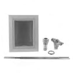
![Slide Ring, 0-ring, and High PFFN-3406 3/4" [20mm]](/docs-images/73/68870517/images/9-3.jpg "Temp.erature Ga.s.ket.")


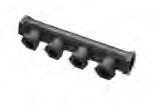
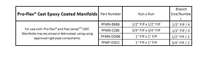
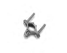
9 Pro Flex 0 Union Part Number Fits Tubing Size F<>r use with: Pro-Flex and PFFN /8" [10mm] Fl a k J acket T '' CSST. Includes: 2 each Retainer Ring, PFFN /2" [15mm] Slide Ring, 0-ring, and High PFFN /4" [20mm] Temp.erature Ga.s.ket. Pro,-Flex 0 Striker Plates Part Number Dimensions PFSP " X 2" F<>r use with: Pro-Flex and PFSP " X 7" FlakJacket CSSi. PFSP ," X 12" PFSP-0617,6"x17" Pro,-Flex 0 Prote,ctive Armor Part Number Fits Tubing Size Length PFFF /8" & 1/2" 1.2" PFFF ' F<>r use with: f>ro-flex and PFFF " 3/4" FlakJa{jket CSST PFFF-1225, 25' PFFF-15,1.2 1" 1.2" PF F F-15,25, 25' 5
10 Additional Items approved as Part of the Pro-Flex Flexible Piping System 6
11 7
, and possible piping routes.")
12 3.0 System Configuration & Sizing Configuration & Sizing Prior to piping installation, refer to building plans or prepare a sketch showing the location of the appliances, the various appliance load demands, point of delivery (location of gas meter or second stage LP regulator), and possible piping routes. Appliance load demand data can be obtained from the manufacturers name-plate located on each appliance, or provided to the system designer by the builder/contractor. a) Determine the local piping restrictions prior to installing the flexible gas piping. Confirm that the local administrative authority has accepted the use of flexible gas piping. Corrugated Stainless Steel Tubing has been accepted by most major code bodies, but local or state adoption of these codes often lags behind. Check with the local administrative authority. b) Determine metered (supply) pressure. Natural Gas: [Check with the local gas utility to determine the pressure supplied by the meter.] Standard low-pressure supply throughout the USA and Canada is typically 6-7 inches water column (also designated as 1/4 PSI or 4 ounces). Higher pressure supply such as 14 inches w.c. (1/2 PSI) and 2 PSI provide significant CSST size reduction. Check with the local gas utility for the availability of elevated pressure. Propane (Liquefied Petroleum Gas): [Check with the propane supplier to determine the pressure supplied] LP is typically supplied within residential buildings at 11 inches w.c. This pressure is set at the second stage regulator. Elevated pressure settings from 14 inches w.c. to 2 PSI and 5 PSI also provide CSST size reductions. Check with the propane gas supplier for available pressure. c) Determine the total capacity needed for all appliances. CFH/BTUH equivalents for natural gas or propane flow can be obtained from the local gas utility or propane supplier. The capacity tables within this guide or any approved CSST tables should be used to determine pipe sizing needed to meet BTUH input load requirements. For natural gas with a specific gravity of 0.60, one cubic foot per hour (1 CFH) is approximately 1,000 BTUH. For propane gas with a specific gravity 1.52, one cubic foot per hour (1 CFH) is approximately 2,500 BTUH. 8
13 3.1.a Series and Parallel (Low Pressure) Systems DETERMINE TOTAL CAPACITY NEEDED FOR APPLIANCES. Data can be obtained from the manufacturers nameplate located on the gas appliance. BTU equivalents for CFH can be obtained from the local utility. In most cases, one Cubic Foot per Hour (1 CFH) is estimated to be 1,000 BTUH heating value (natural gas) and Propane has a heating value around 2,500 BTUH, making the capacity tables easy to utilize with appliance BTU input loads. DETERMINE THE TYPE OF PIPING LAYOUT WHICH BEST FITS THE INSTALLATION SERIES SYSTEMS A series layout is the most common arrangement utilized for rigid pipe systems for low pressure. These usually consist of a main run (header) with tees branching off to each appliance. In a traditional series system, the service pressure down stream of the meter is typically less than 1/2 PSI. The minimum pressure supplied to any given appliance is an important consideration. To operate properly, most Natural Gas appliances require a minimum of 4 WC pressure and most Propane (Liquefied Petroleum) appliances require a minimum of 10 WC pressure. Allowable pressure drop along any particular run may be dictated by local code restrictions. PARALLEL SYSTEMS In a parallel system, appliances are serviced by individual runs that stem off from a central distribution manifold. A main run from the meter supplies the manifold. The manifold station is located close to the greatest load, typically the boiler or furnace. A parallel layout is most likely to be used in 1/4 to 1/2 psi systems. 3.1.b Dual Pressure Systems A dual pressure system incorporates two operating pressures downstream from the meter. The first pressure, set by the service regulator at the meter, is usually 2 psi, but can be higher or lower depending on code restrictions and gas company policy. This part of the system is sized separately and ends at the pounds-toinches regulator inlet. The allowable pressure loss for this part of the system must be added to the effect of the regulator to determine the available pressure at the regulator outlet. See chart page 36, Regulator Capacity Table. The second pressure, at the outlet of the pounds-toinches regulator is under 1/2 PSI, usually 8 WC for natural gas and 11 WC for propane. Generally, a parallel system requires a higher total footage of smaller diameter tubing and fewer fittings compared to a series layout. MULTI-UNIT APARTMENT BUILDING 9
14 Multiple Manifold Systems For those installations in which the energy load demand is large or the appliances are installed throughout the structure with long distances from the meter, a multiple manifold system may be used. Elevated pressure systems are a safe, efficient method of providing for larger BTU load demands while maintaining smaller pipe diameters. MULTIPLE MANIFOLD SYSTEMS Combination Steel/CSST System (Hybrid) In a hybrid system, corrugated stainless steel tubing is used in combination with rigid pipe or copper tubing. In lower pressure systems it is often advantageous to use both CSST and rigid pipe to help minimize pressure drops typically encountered on systems with high loads and/or long runs. Pro-Flex Flexible Gas Piping systems [both Pro-Flex & l k Flak Jacket TM ] are approved for use in combination with all approved fuel gas-piping materials by using approved pipe threads at the interface. HYBRID SYSTEM Elevated Pressure System In a complete elevated pressure system, corrugated stainless steel tubing is used to deliver pressures in excess of 1/2 psi to a pounds-to-inches regulator positioned directly in front of each appliance regulator. This is an alternate method of installation used to minimize pressure drops typically encountered on systems with high loads and/or long runs. ELEVATED PRESSURE SYSTEM 10
15 ALLOWABLE PRESSURE DROP: Pro-Flex gas piping systems [both Pro-Flex CSST and Flak Jacket TM ] are required to be tested, listed and installed" in accordance with the ANSI/CSA standard for fuel gas piping systems using corrugated stainless steel tubing, ANSI LC-1/ CSA This standard, among other things, requires the manufacturer to provide installation instructions including the necessary pipe sizing tables and methods. With respect to gas piping sizing, the intent of all model codes is to ensure there is sufficient gas volume and gas pressure supplied to the appliance for proper operation. Language from the International Fuel Gas Code clearly illustrates this point. Allowable pressure drop - The design pressure loss on any piping system under maximum probable flow conditions, from point of delivery to the inlet connection of the equipment, shall be such that the supply pressure at the equipment is greater than the minimum pressure required for proper equipment operation. Natural gas appliances are typically designed to operate with a minimum inlet pressure of 4.0 inches water column. Propane appliances are typically designed to operate with a minimum inlet pressure of 10.0 inches water column. The natural gas capacity tables published by Pro-Flex, LLC, for use with Pro-Flex and Flak Jacket TM CSST, shall be used to provide for no less than 5 water column pressure to the appliance inlet. The propane capacity tables shall be used to provide no less than 10.5 water column pressure to the appliance inlet. This can be done by subtracting the desired appliance inlet pressure (5 WC for NG, 10.5 WC for LPG) from the gas source pressure (gas meter for NG, second stage regulator for LPG) to get allowable pressure drop. Use the Pro-Flex capacity table labeled with the appropriate allowable pressure drop and gas type. This will result in an additional pressure drop capacity over the commonly used 1/2 WC drop associated with the Longest Run Method. Allowable Pressure Drop along any particular run may be dictated by local codes. Reference Data for Proper System Sizing: PRESSURE CONVERSION FACTORS FUEL GAS INFORMATION 1/4 psi = in w.c. = (approx. 7 WC) Natural Gas Propane 1/2 psi = in w.c. = (approx. 14 WC) BTU per Cubic Foot = psi = in w.c. = (approx. 28 WC) Specific Gravity = psi = in w.c. = (approx. 56 WC) 5 psi = in w.c. = (approx. 140 WC) Note: to determine the CFH of Natural Gas, divide by BTU load by To determine the CFH of Propane, divide the BTU by
16 3.2 Sizing Methods and Examples SIZING PROCEDURES FLAK JACKET TM & PRO-FLEX CSST, FLEXIBLE GAS TUBING LONGEST LENGTH METHOD EXAMPLE #1 This is a low-pressure series system with four natural gas appliances. The utility company supply pressure exiting the meter is 6 inches water column, and the maximum allowable pressure drop across the longest length from the meter to the farthest appliance is 1/2 inch water column. The gas supplied has a specified gravity of.60 and an energy content of 1 cubic foot per hour equals 1,000 BTU per hour. APPLIANCE LOADS +GAS LOAD LENGTH OF RUN FURNACE 75 CFH (75,000 BTUH/1000 PER CFH) 14 FEET OVEN/RANGE 45 CFH (45,000 BTUH/1000 PER CFH) 20 FEET DRYER 25 CFH (25,000 BTUH/1000 PER CFH) 38 FEET WATER HEATER 24 CFH ( BTUH/1000 PER CFH) 50 FEET TOTAL CFH LENGTH OF EACH RUN A = 8 FEET EXAMPLE: B = 10 FEET Furnace: A (8 ft) + F (6 ft) = 14 FEET C = 12 FEET Oven/Range: A (8 ft) + B (10 ft) + E (2 ft) = 20 FEET D = 20 FEET Dryer: A (8 ft) + B (10 ft) + C (12 ft) + G (8 ft) = 38 FEET E = 2 FEET Water Heater: A (8 ft) + B (10 ft) + C (12 ft) + D (20 ft) = 50 FEET F = 6 FEET THE LONGEST RUN IS FROM THE METER TO THE WATER HEATER; OVER 50 FEET. G = 8 FEET SIZING SECTION A: Length A must be sized to handle the total load of all appliances and the total pressure drop from the meter to the farthest appliance. The total appliance load is 169 CFH. Using the longest length sizing method, the length is 50 ft. to the water heater. Referring to Table 1, (6" WC inlet pressure and 1/2" WC pressure drop) under the 50 ft. length column, we find that 1 inch size has the flow capacity exceeding 169 CFH (171 CFH). Use 1" tubing to run Section A. SIZING SECTION B: Section B must supply the water heater, dryer and range. The total pressure drop for the system is considered to be from the meter to the water heater (farthest appliance). The total appliance load is = 94 CFH. Using the longest length sizing method, the length is 50 ft. (distance from meter to water heater). Referring to Table 1 under the 50 ft. length column, we find that size 1 inch has flow capacity over 94 CFH (171 CFH). Use 1" tubing to run Section B. SIZING SECTION C: Section C must supply the water heater and dryer. The total appliance load is = 49 CFH. Using the longest length method, the length is 50 ft. Referring to Table 1 under the 50 ft. length column, we find that 3/4 inch has flow capacity above the 49 CFH (89 CFH) Use 3/4" tubing to run Section C. SIZING SECTION D: Section D must supply the water heater. The total appliance load is 24 CFH. Using the longest method, the length is 50 ft. Referring to Table 1 under the 50 ft. length column, we find that 1/2 inch has flow capacity above 24 CFH (32 CFH). Use 1/2" tubing to run Section D. SIZING SECTION E: The total appliance load is 45 CFH. Using the longest length method, the length is 50 ft. Referring to Table 1 under 50 ft. length column, we find that 3/4" has flow capacity above 45 CFH (89 CFH) Use 3/4" tubing to run Section E. SIZING SECTION F: The total appliance load is 75 CFH. Using the longest length method, the length is 50 ft. Referring to Table 1 under 50 ft. length column, we find that 3/4" has flow capacity above 75 CFH (89 CFH) Use 3/4" tubing to run Section F. SIZING SECTION G: The total appliance load is 25 CFH. Using the longest length method, the length is 50 ft. Referring to Table 1 under 50 ft. length column, we find that 1/2" has flow capacity above 25 CFH (32 CFH) Use 1/2" tubing to run Section G. 12
17 EXAMPLE #2, MEDIUM PRESSURE PARALLEL SYSTEM This is a medium-pressure parallel system which includes a distribution tee manifold. The natural gas supply pressure is 1/2 psig and the maximum allowable pressure drop from the meter to the farthest appliance is 6" WC. Medium Pressure (1/2 psig) Natural Gas (Parallel System) Appliance Loads Lengths size A = 10 FT 3/4" Oven/Range 45 CFH B = 20 FT 3/8" Furnace = 75 CFH C= 5 FT 3/8" Dryer = 25 CFH D= 35 FT 3/8" Water Heater = 24CFH E = 50 FT 3/8" TOTAL CFH CFH SIZING, SECTION A: Determine distance from the meter to the farthest appliance (water heater 60 ft.) Determine the total appliance load supply by Section A (169 CFH). Referring to Table 4 under the 60 ft. length column, we find 3/4 inch has flow capacity above 169 CFH (274 CFH). Use 3/4" tubing to run Section A. SIZING SECTION B: Section B supplies the oven/range. The total pressure drop is considered from the meter to the oven/range. The total appliance load is 45 CFH and the length is 10 ft + 20 ft. = 30 feet total. Referring to Table 4 under the 30 ft. length col-umn, we find that 3/8 inch has a flow capacity above 45 CFH (94 CFH). Use 3/8" tubing to run Section B. SIZING SECTION C: Section C supplies the furnace. The total appliance load is 75 CFH and the total length is 10 ft. + 5 ft. = 15 ft total. Referring to Table 4 under the 15 ft. length column. We find that 3/8 inch has a flow capacity above 75 CFH (134 CFH) Use 3/8" tubing to run Section C. SIZING SECTION D: Section D supplies the dryer. The total appliance load is 25 CFH and the total length from the meter is 10 ft ft. = 45 feet total. Referring to Table 4 under the 45 ft. length column. Since 45 ft. does not appear in the table, use the next longest run column of 50 ft. We find that 3/8 inch has a flow capacity above 25 CFH (73 CFH) Use 3/8 tubing to run Section D. SIZING SECTION E: Section E supplies the water heater. The total appliance load is 24 CFH and the total length from the meter to appliance is 10 ft + 50 ft = 60 feet total. Referring to Table 4 under the 60 ft. length column, we find that 3/8 inch has a flow capacity above 24 CFH (65 CFH) Use 3/8" tubing to run Section E. 13
18 EXAMPLE #3 - ELEVATED DUAL PRESSURE SYSTEM This is a 2 psig supply pressure parallel arrangement. The natural gas system incorporates a pressure reducing regulator with a distribution tee manifold located closely to several large capacity appliances. The inlet pressure downstream of the meter is 2 psig, and the designated maximum pressure drop from the meter to the reducing regulator is 1.0 psig. The outlet pressure from the regulator is set at 8 inches water column. A 3" WC pressure drop is used in sizing the tubing from the regulator outlet to each appliance. Specific gravity of the gas delivered is.60 and energy content is 1 CFH = 1,000 BTUH. Elevated (2 psig) Dual Pressure Natural Gas (Parallel System) Total load and regulator size: Calculate the total appliance load and determine if one regulator has sufficient capacity to supply this load. One regulator is normally adequate when appliances are close together. When groups of high-load appliances are widely separated, it is often more economical to use one pressure reducing regulator to supply each appliance group. The total appliance load required is 169 CFH (169,000 BTUH). APPLIANCE LOADS LENGTHS TUBE SIZE METER TO REGULATOR A= 10 FEET 3/8" OVEN/RANGE = 45 CFH B = 20 FEET 3/8" FURNACE = 75 CFH C = 5 FEET 3/8" DRYER = 25 CFH D = 35 FEET 3/8" WATER HEATER=24 CFH E = 50 FEET 3/8" TOTAL CFH The supply pressure from the meter is 2 psig and the designated pressure drop from the meter to the regulator is 1 psig; thus the minimum inlet pressure to the regulator is 1 psig. Since the outlet pressure of the regulator is set at 8" WC, the expected pressure drop across the regulator is 20 inches WC (1 psig - 8" WC = 20" WC). A single regulator has a flow rate capacity of 252 CFH. This capacity exceeds the system requirement of 169 CFH. In cases where the regulator capacity is insufficient, a larger #325-5A regulator or parallel arrangement of two regulators should be used. SIZING SECTION A (METER TO REGULATOR): Section A must be sized to handle all appliances loads and supply the pressure reducing (pounds to inches) regulator. The total load is 169 CFH and the length is 10 ft. The supply pressure is 2 psig and the pressure drop is 1 psig. Referring to Table 5 (meter to regulator with 2 psig inlet and 1 psig drop) under the 10 ft. column, we find that 3/8 inch has capacity over 169 CFH (332 CFH). Use 3/8" tubing to run Section A. To size the other sections, the pressure source is the outlet of the pressure regulator rather than the meter. Use the low-pressure Table 3 (8.0" WC inlet with 3.0" WC drop) and size each section individually using the appliance load and run distance. SIZING SECTION B Section B supplies the oven/range. The load is 45 CFH and the distance between the regulator outlet and appliance is 20 ft. The total pressure drop is from the outlet of the reducing regulator to the oven/range. The outlet pressure from the regulator is 8" WC and the pressure drop is 3" WC. Referring to Table 3, under the 20 ft. length column, we find that an 8 inch has a flow capacity above 45 CFH (81 CFH). Use 3/8" tubing to run Section B. SIZING SECTION C: Section C supplies the furnace. The load is 75 CFH and the distance is 5 ft. Referring to Table 3, under the 5 ft. length column, we find that 3/8 inch has a flow capacity above 75 CFH (162 CFH). Use 3/8" tubing to run Section C. SIZING SECTION D: Section D supplies the dryer. The load is 25 CFH and the distance is 35 ft. Referring to Table 3, and since a 35 ft. length column does not exist, use the 40 ft. length column. We find that 318 inch has a flow capacity above 25 CFH (58 CFH). Use 3/8" tubing to run Section D. SIZING SECTION E: Section E supplies the water heater. The load is 24 CFH and the distance is 50 ft. Referring to Table 3, under the 50 ft. length column, we find that 3/8 inch has a flow capacity above 24 CFH (51 CFH). Use 3/8" tubing to run Section E. 14
19 COMBINATION STEEL/ CSST (Hybrid System) (Hybrid system) It is often to your advantage to use both CSST and rigid pipe to help minimize pressure drops typically encountered on systems with high loads and/or long runs. Flexible gas piping systems by Pro-Flex, LLC [both Pro-Flex CSST and Flak Jacket TM ] are approved for use in combinations with approved gas piping materials by using approved pipe threads at the interface. For sizing use longest run method assuming the complete run is CSST. 15

 are to be used as part of the piping system in the installation.")
![Tubing or fittings from other manufacturer' CSST systems shall not be intermingled with Pro-Flex tubing [Flak Jacket TM or Pro-Flex CSST] or fittings.](/docs-images/73/68870517/images/20-3.jpg "Never use Pro-Flex flexible gas piping or components as a ground electrode or as a grounding path for appliances or electrical systems.")
20 4.0 Installation Practices 4.1 General Installation Practices Pro-Flex flexible gas piping systems [both Pro-Flex CSST and Flak Jacket TM ] may only be installed by a Qualified/ Trained installer who has been trained in the use of Pro-Flex. A Pro-Flex /Flak Jacket TM Qualified installer card is required to purchase and install Pro-Flex 's flexible gas piping. Only the components provided or specified by Pro-Flex, LLC, (including Pro-Flex's striker plates and floppy flex armor conduit) are to be used as part of the piping system in the installation. Tubing or fittings from other manufacturer' CSST systems shall not be intermingled with Pro-Flex tubing [Flak Jacket TM or Pro-Flex CSST] or fittings. Never use Pro-Flex flexible gas piping or components as a ground electrode or as a grounding path for appliances or electrical systems. Pro-Flex flexible gas piping systems [both Pro-Flex CSST and Flak Jacket TM ] routed in a location which is concealed, constrained, and within 3 inches of a potential threat will be protected against damage by protection devices listed in the Pro-Flex Installation/Training Guide. The extent of protection is defined as follows: a. At all points of penetration less than 2 inches [50.8mm] from any edge of a stud, joist, plate, etc., a striker plate is required to provide protection at the area of support and within 5 inches [127mm] of each side [if appropriate] of the support. b. At points of penetration 2 to 3 inches [ mm] from any edge of a stud, joist, plate, etc., a striker plate is required to provide protection throughout the area of support. c. At points of penetration greater than 3 inches [76.2mm] from any stud, joist, plate, etc., no protection is required. d. Tubing routed horizontally through studs shall be protected from puncture threats using shielding devices provided. Piping that is constrained by rigid foam insulation shall be protected along it's entire length. In addition, any exposed stainless that may come in contact with spray foam insulation must be wrapped with self sealing silicone tape. CSST greater than 1 inch [25.4mm] inside diameter installed within hollow wall cavities of 2 x 4 construction shall be protected along the entire concealed length using the shielding devices specified by the manufacturer. The width of the installed striker plate, at the point of penetration through studs, joists, plates, etc., shall be at least 1.5 times the outside diameter of the tubing. Open ends of the tubing are to be temporarily plugged or taped closed prior to installation to prevent the entrance of dirt or other debris. Contact with sharp objects and harmful substances are to be avoided. The protective jacket should be kept in place as much as possible to protect the tubing from corrosive threats. Contact with chemicals containing chlorides or ammonia [ these chemicals include leak test solutions, fluxes used to solder copper tubing, and acid based cleaners used to wash masonry] must be followed by a thorough rinse with water and wipe dry. Installation clearance holes for routing CSST are to be approximately 1/2" larger than the outside diameter of the CSST [see Table 4.1]. Drilling of any structural member must be in conformance with local building codes. CSST tubing shall be supported with pipe straps, bands or hangers suitable for the size and weight of the tubing, at intervals not to exceed those shown in Table 4.2. When supporting CSST tubing runs, the use of other conductive systems such as vents, ducting, piping and cables [electrical or communication] are prohibited. Recommended Minimum Bend Radius for CSST [ see Table 4.3]. Table 4.1 Table 4.2 Table
21 Connections to moveable appliances such as ranges and clothes dryers should be accomplished with a flexible gas appliance connector. Regulators are suitable for multi-poise mounting. When using a vent limiting device, the regulator must be mounted in a horizontal upright position. For outdoor venting, the vent line must be at least the same size as the vent connection and no longer than 30 feet before upsizing. When mounting a regulator outdoors, remove the vent limiting device and position regulator inverted with open port down. A manifold assembly utilizing a pounds-to-inches regulator shall include a shut-off valve ahead of the regulator and installed in an accessible location so that the regulator can be inspected, maintained and serviced if necessary. Buried or Embedded: CSST shall not be buried directly in the ground or directly embedded in concrete (i.e.: patio slabs, foundations and walkways) When it is necessary to bury or embed CSST, the tubing shall be routed inside a non-metallic, watertight conduit that has an inside diameter at least 1/2 inch greater than the O.D. of the CSST tubing. For ends of conduit installed outdoors, the conduit shall be sealed at any exposed end to prevent water form entering. No mechanical joint fittings are permitted within the conduit. Note: CSST must be buried in accordance with all local building codes. Pro-Flex flexible gas piping systems [Flak Jacket TM and Pro-Flex CSST] must be pressure tested for leaks during rough construction in accordance with all local codes. In the absence of local requirements, test in accordance with Part 4 of the NFPA 54, National Fuel Gas Code ANSI Z223.1 and/or CSA B149.1 Installation Codes or in accordance with the requirements of the applicable local codes. For a one-part pressure-test, the regulator shall be removed from the system. For a two-part test, the regulator should be isolated from downstream test pressures. Alongside a structure: When installed alongside a structure, between the ground and a height of 6 feet, in an exposed condition, the CSST shall be protected from mechanical damage inside a conduit or chase. A conduit or chase is not required if the tubing is installed in a location that will not subject the tubing to mechanical damage. Meter Hook-Ups. Refer to the Pro-Flex installations and illustrations shown in this training guide. CSST shall not be used as a means of support for the gas meter. Also check with your local code official or authority having jurisdiction on meter hook-ups. Some restrictions may apply. Local code requirements will always take precedence. For a Piping system which includes manual gas valves listed as complying with ASME B Manually operated metallic gas valves for use in above ground piping systems up to 5 psi. An approved valve must be used. Pro-Flex Flexible Gas Piping (Flak Jacket TM or Pro-Flex CSST) shall not be directly routed into a metallic gas appliance enclosure that penetrates the roof-line. The connection shall be outside of the enclosure to a section of rigid pipe or stub-out. In instances where the appliance is not vented above the roof-line, such as decorative fireplaces, the CSST tubing must be protected by grommets, bushing or armor (Floppy-Flex) tape tape, shrink sleeve material or a minimum of four (4) wraps of #10 Mil Duct-Tape. This is to ensure that no physical contact will be made between will be made between the metal and the CSST tubing that could cause mechanical wear. Pro-Flex, LLC requires direct bonding for Pro-Flex [yellow] CSST in accordance with NFPA 54 Section Pro-Flex, LLC has no additional bonding requirements for Flak Jacket TM Arc-Resistant CSST [ it must be bonded in the same manner as rigid pipe per NFPA 70 Article (B)]. However, installers must always comply with any local requirements which may be more strict than these instructions. See section 4.10 of this guide for detailed bonding instructions. 17


![STEP #4 By hand, open Retainer Ring [split stainless steel] wide enough to fit in the fourth [4th] valley and](/docs-images/73/68870517/images/22-3.jpg "squeeze ring by hand to close. Do not break the retainer ring in half.")
![STEP #5 Place Slide [solid stainless steel] Ring over the tube end and slide it down to the Retainer Ring.](/docs-images/73/68870517/images/22-4.jpg "STEP #6 Roll Silicone O-Ring [red/orange] over tube end and roll/ slide it down to meet the slider ring.")
![STEP #7 Ensure the high temperature gasket [brown] is in place in the base of the fitting.](/docs-images/73/68870517/images/22-5.jpg "Patented System #5,845,946; #5,857,718; 6,102,445 Jacket cut and removed inside the 4th valley from the end of")


22 4.2 Fitting Assembly ASSEMBLY PROCEDURES FOR PRO-FLEX & FLAK JACKET TM CSST STEP #1: Secure NPT end of the fitting to the fixed connection. Use appropriate sealant on the NPT threads. STEP #2: Using a utility knife or scissor-style plastic pipe cutter, cut through the coating [around the entire circumference of the jacket] in the fourth [4th] valley and remove jacket from the tubing end. Note: Carefully cut jacket material only. STEP #3 Slide nut over CSST tubing with threaded end pointing toward cut end of tubing. STEP #4 By hand, open Retainer Ring [split stainless steel] wide enough to fit in the fourth [4th] valley and squeeze ring by hand to close. Do not break the retainer ring in half. STEP #5 Place Slide [solid stainless steel] Ring over the tube end and slide it down to the Retainer Ring. STEP #6 Roll Silicone O-Ring [red/orange] over tube end and roll/ slide it down to meet the slider ring. STEP #7 Ensure the high temperature gasket [brown] is in place in the base of the fitting. Patented System #5,845,946; #5,857,718; 6,102,445 Jacket cut and removed inside the 4th valley from the end of the tube. STEP #8 Place tube into fitting end. Tighten nut hand tight, then tighten nut additional 1/4 to 1/2 turn with a pair of wrenches. Do not use thread sealant on the threads where the nut threads onto fitting. When installing Flak Jacket TM Arc-Resistant CSST, any exposed stainless steel must be covered by wrapping with self-bonding silicone tape [such as PFRT-50P] 1. Polyethylene Jacket [Yellow or Black] Stainless Steel Corrugated Tubing 3. Brass Mechanical Nut 4. Brass Mechanical Fitting 5. Silicone O-Ring [orange/red] Stainless Steel Slide Ring [solid] Stainless Steel Slide Ring [split] 8. High Temperature Gasket [brown] 18

23 Proper Cutting of Flak Jacket TM and Pro-Flex CSST CSST is to be cut with a tubing cutter. The cut is to be made in a valley between corrugations. Use light pressure [too much pressure may deform the tube where it is being cut] and multiple revolutions, tighten the cutter approximately 1/4 turn per revolution. The cut is to be free of burrs and distortions. After the tubing has been cut, trim the jacket. Use a sharp utility knife or scissorsstyle plastic tubing cutter with the blade positioned in the 4th valley; cut around the diameter of the tube and remove the small piece of the jacket. Trouble Shooting / Re-assembling a Mechanical Fitting CORRECTING LEAKS Gradually tighten fitting until leak stops 2. If tightening does not stop after reaching maximum torque of 35 lbs or 50 lbs [refer to maximum torque for each size listed below]. STOP and open assembly and check... a. To see if they are properly assembled. If not correct, go through assembly steps and test again for leaks. b. Check to see that no foreign material is in assembly. If so, clean out and re-assemble and test again for leaks. c. Check to see that none of the assembly pieces are cracked. If so, replace, re-assemble and test again for leaks. d. Ensure use of Pipe tape or Pipe Dope on NPT Threaded Ends. How to Disassemble a Pro-Flex Mechanical Fitting: a. Remove nut b. Remove Retainer Ring first, then Slide Ring, then O-ring. c. Replace any damaged component. d. Re-Assemble per instructions on page 18. Maximum Allowable Nut Tightening Torques for Connecting Fittings to Corrugated Stainless Steel Size of Fitting Tubing Maximum Allowable Tightening Torque 3/8" (10mm) 35 ft.-lb. 1/2" (15mm) 35 ft.-lb. 3/4" (20mm) 50 ft.-lb. 1" (25mm) 50 ft.-lb. 1 1 /4" (31mm) 50 ft.-lb. TORQUING METHOD FOR FIELD ASSEMBLY To achieve the proper Torque without a torque wrench, first tighten the fitting adapter to the nut until resistance to hand tightening is so that you can no longer continue. Then, using a crescent wrench, tighten to 1/4 to 1/2 turn. CAUTION: DO NOT OVER TIGHTEN! 19
24 4.3 Routing Flexible gas piping systems manufactured by Pro-Flex, LLC [both Flak Jacket TM & Pro-Flex CSST] can be routed beneath, through and along side floor and ceiling joists. Consideration must be given to future construction possibilities. Care should be taken when installing to maintain as much separation as reasonably possible from other electrically conductive systems in the building. Pro-Flex & Flak Jacket TM can be routed inside hollow wall cavities. This is the preferred for vertical sections of piping rather than horizontal sections. Avoiding horizontal runs through the walls will minimize the need for protection. When constrained from moving by spray foam insulation, the tubing must be protected from puncture by the specified protective devises. Pro-Flex & Flak Jacket TM can be routed on top of ceiling joists. This is the preferred method of routing in areas where slab-on-grade construction is prevalent and is considered to be supported by the joists. Pro-Flex & Flak Jacket TM are listed to ANSI LC- 1 - CSA 6.26, which includes testing for suitability for exposure of CSST piping systems to outdoor environments. Note: Note: Note: Care should be taken when installing any type of fuel gas piping (Inc: CSST, Iron or Copper) to maintain as much separation as reasonably possible from other electrically conductive systems in the building. Manufactuer s design and installation instructions, or instructions supplied with the part by the valve manufacturer, shall include data on sizing and pressure drop across the device as a function of flow (up to the activation flow rate) for each size valve.when an excess flow valve is supplied as part of the gas piping system, the CSST. Consult local building codes as to required separations for CSST from such conductive systems including metallic chimney liners, metallic appliance vents, metallic ducting and piping and electrical cables. Through Wall Penetrations and Plenums FIRE STOPS: Pro-Flex CSST with its polyethylene yellow jacket has been tested to the flame spread and smoke density requirements of ASTME84 and meets limits imposed for this criteria. Pro-Flex nonmetallic coating has an ASTME-E84 flame spread of less than 25 and ASTM-E84 smoke density of less than 50. Other requirements for the fire rated resistive constructions may be imposed by local codes. The qualified/trained installer must meet local building codes with respects to flame and smoke density regulations for non-metallic materials at all times. For Flak Jacket TM Arc-Resistant CSST with its black jacket, the installer shall address local building codes with respect to flame spread and smoke density requirements for non-metallic materials, Pro-Flex, LLC recommends either removing the black jacket or transitioning to rigid pipe when passing through such areas. 20
25 Outdoor Installation Guidelines a) OUTDOORS: When Pro-Flex or Flak Jacket TM CSST are installed outdoors, the external jacket shall remain intact as much as possible for the given installation. Any portions of the exposed stainless steel tubing shall be wrapped with self bonding silicone tape [PFRT-50P] or sleeved to prevent later threats by acids or chlorides such as cleaning solutions for masonry. b) BURIED or EMBEDDED: Pro-Flex & Flak Jacket TM CSST SHALL NOT be buried directly in the ground or directly embedded in concrete (patio slabs, foundations or walkways) When necessary, to bury or embed CSST, the tubing shall be routed inside a non-metallic, watertight conduit that has an inside diameter at least 1/2 inch larger than the O.D. size of the CSST tubing. The ends of the conduit installed outdoors, must be sealed at any exposed end to prevent water from entering. NOTE: No mechanical joint fittings are permitted in the conduit. (See page: 20) c) ALONG SIDE A STRUCTURE: When Pro-Flex or Flak Jacket TM CSST are installed along the outside of a structure (between the ground and a height of 6 ft) in an exposed condition, the CSST tubing shall be protected from mechanical damage inside a conduit or chase. A conduit or chase is not required if the tubing is installed in a location that will not subject the CSST to mechanical damage. Typical Installations of CSST With Non-Metallic Conduit Embedded In Concrete Slab Typical Installation of CSST With Non-Metallic Conduit Buried Under Concrete Slab 21


26 Clearance Holes & Notching a. Bored Holes - In locations where CSST is installed through bored holes in joists, rafters, or wood members, holes shall be bored so that the edge of the hole is not less than 2 in. (50.8 mm) from the nearest edge of the wood member. Where this distance cannot be maintained at any point, the CSST shall be protected by a listed striker plate of the appropriate length and width installed in accordance with the manufacturers installation instructions. The diameter of the bored holes shall be a minimum of 1/2 in. (12.7 mm) larger than the outside diameter of the tubing. b. The size of the hole drilled through top plates, top frame members, and sole plates, to allow the vertical passage of the tubing, shall not exceed 1/2 of the width of the member. The hole should be bored through the center of the member. (See figure 4-1.) c. Where soles or plates are cut for tubing, the width of the cut shall be 1/2 in. (12.7 mm) larger than the outside diameter of the tubing but not greater than 2 in. (50.8 mm), and the tubing must be protected with a listed striker plate of the appropriate length and width installed in accordance with the manufacturers installation instructions. (See figure 4-1.) d. Where a hole is to be bored in a joist, the hole should be located at the centerline, otherwise no closer than 2 in. (50.8 mm) from the nearest edge of the joist, and the hole diameter shall not exceed 1/3 the depth of the joist. (See figure 4-2.) FIGURE 4-3 Holes in Non-Bearing Walls No more than two successive double board studs permitted FIGURE 4-4 Holes in Bearing Walls FIGURE 4-1 Holes and Cuts in Top and Sole Plates The size and depth of installation clearance holes or notches for routing the tubing through wall studs and joists shall comply with the requirements of the local building code. CSST THROUGH METAL FRAMING a. When CSST passes through metal framing members, it shall be installed and protected in accordance as follows: b. When using Pro-Flex Flexible Gas Piping (CSST) through Metal framing the CSST tubing must be protected by grommets, bushing or armor (Floppy-Flex ), PVC tape, shrink sleeve material or a minimum of four (4) wraps of #10 Mil Duct-Tape. This is to ensure that no physical contact will be made between the metal and the CSST tubing that would cause mechanical wear. FIGURE Holes in Wood Joists DRILLING: Drilling holes should be made approx. 1/2 greater than the outside diameter of the CSST Tubing. e. Where holes are to be bored in non-bearing vertical members of the wall framing, the size of such holes shall not be larger than 60 percent of the width of the member. (See figure 4-3.) f. Where holes are to be bored in bearing vertical members of the wall framing, the size of such holes shall not be larger than 40 per-cent of the width of the member. Holes up to 60 percent of the member s width are permitted if the members are doubled. No more than two successive double bored members are permitted.(see figure 4-4.) g. Installing CSST in notches cut in either the top or bottom of joists are prohibited. 22
27 CONCEALED FITTINGS LOCATION Pro-Flex, LLC's Mechanical Fittings have been tested and listed per the requirements of ANSI LC-1 - CSA 6.26 for concealed use. The fitting may be used for concealed attachment to appliance valves, branch runs using tee fittings, and length splices. These guidelines address some of the most common situations where concealing the fittings is the only practical alternative. These guidelines cannot address all applications of concealed fittings, but instead, provide typical instructions to demonstrate the principles that apply to fittings listed for installation in concealed locations. (reference National Fuel Gas Code, NFPA 54, Section 3.4.2) a) New Installations - When multiple gas outlets are supplied from a single run of CSST, each downstream outlet branch can be connected to the main run using a tee-type fitting which can be located in a concealed location. b) Fireplace "key valves" - Flexible piping connections to fireplace key valves can be located in a concealed location, when accessibility is not readily provided. c) Exclusion - Manifold stations (2 PSI system), which include the multi-port manifold, shut-off valve and pressure regulator, shall not be installed in concealed locations regardless of the qualifications of the tubing. Modifications to Existing Systems a) New Ceilings in Unfinished Rooms/Basements - CSST fittings originally installed in accessible ceiling locations can be concealed in the event a ceiling is installed at a later date. b) Extensions to Existing Tubing Runs - A concealed tubing can be modified to permit an extension to another appliance location provided there is sufficient capacity to supply both appliances at the same time. If an accessible location for the modification is not available, the existing tubing run can be modified with a tee fitting which will result in a concealed fitting behind the wallboard. c) Repairs to Existing Tubing Runs - Damaged tubing runs shall be repaired in accordance with the instructions in this guide. The repair can result in a line splice that may ultimate-ly be located in a concealed location. d) Concealed tubing shall be protected from puncture threats, using the shielding devices specified by the manufacturer, at all points of penetration through studs, joists, plates or similar structures. The extent of protection shall be defined as follows: 1. At points of penetration less than 2 in (50.8 mm) from any edge of a stud, joist, plate, etc., a listed striker plate is required to provide protection at the area of sup-port and within 5 in (127 mm) of each side (if appropriate) of the support. 2. At points of penetration 2 to 3 in (50.8 mm to 76.2 mm) from any edge of a stud, joist, plates, etc., a listed striker plate is required to provide protection throughout the area of support. 3. At points of penetration greater than 3 in (76.2 mm) from any edge of a stud, joist, plate, etc., no protection is required. 4. Tubing routed horizontally through studs shall be protected from puncture threats between the studs using the shielding devices provided. 5. CSST greater than 1-in (25.4 mm) inside diameter installed within hollow cavity walls of 2 x 4 construction shall be protected along the entire concealed length in the manner and using the shielding devices specified by the manufacturer. 6. The width of the installed striker plate, at the points of penetration through wall studs, floor joists, plates, sills, etc., shall be out at least 1.5 times the outside diame-ter of the tubing. 23


 of an interior surface.")
28 4.4 Protection PROTECTION IS REQUIRED WHEN CSST TUBING IS CONCEALED, CONSTRAINED AND WITHIN 3 INCHES OF A POTENTIAL THREAT. FIGURE 4-12 Pro-Flex & Flak Jacket TM must be protected where puncture or other physical damage threats exist. Install protection devices, i.e. striker plates as shown, to protect the installed tubing from penetrations by drill bits, nails, screws and in those areas where the tubing is concealed and will not be free to move to avoid such puncture threats. [This includes areas where the tubing is constrained by spray foam insulation.] Flexible gas tubing must be protected when it is concealed, constrained, and within 3" [76.2mm) of an interior surface. A 2 x 4 will always require protection because any and all clearance holes for tubing will be less than 3" [76.2mm] away from the edge. Protection/Shielding is required 5" [127mm] [each side where appropriate] beyond the support area when points of penetration are less than 3" [76.2mm] from any edge of structural members. Refer to figures 4-10, 4-11, 4-15, 4-16, and 4-18 for examples. r examples. Where Finished Exterior Wall Does Not Permit Installation of Striker Plate, Protective Sleeve is Required. Install Floppy-Flex strip wound steel conduit, which is another protection device, which can and should be used at points of support such as gas outlet terminations, short tubing runs and where tubing is routed horizontally between studs. Strip wound (Floppy-Flex) is required along the length within a wall partition when tubing cannot be displaced a minimum of 3" (76.2mm) or if distances between supports are less than 2 ft. NOTE: The ID of the conduit [Floppy-Flex] must be at least 1/2" larger than the OD of the CSST Tubing. FIGURE 4-10 FIGURE 4-11 Long Unsupported Vertical Tubing Rugs (over 3 ft.) within a Hollow Interior Wall Partition. Shielding Required at Support Area When Points of penetration are Less than 2" From any Wall Surface. When the exterior wall is finished before the installation of the gas tubing and a striker plate cannot be installed, a protective schedule 40 steel pipe sleeve shall be placed around the tubing. The sleeve shall be secured to the sill or stud, be at least 1/2in. (12.7mm) larger in its internal diame-ter than the O.D. of the CSST, and extend no more than 4 in.(100 mm) above the sill or beyond the stud. A striker plate shall also be placed on the accessible side of the sill or stud as required. Figure 4-13 Figure 4-14 Only Pro-Flex supplied, hardened striker plates, listed for use with CSST systems may be used. Long Unsupported Vertical Tubing Run (over 3 ft.) from a Termination Outlet Within a Wall Partition. Shielding Required At Termination Outlet and Along Tubing Length That Is Non-supported and Cannot Be Displaced a Minimum of 3 in. in the Direction Away From Potential Penetration. 24
29 Floor CSST Tubing Support Floor Joists 3" or less Striker Plates Figure 4-15 Figure 4-18 CSST Tubing Going Through Joists Within 3" of Potential Nailing Surface. Short Unsupported Tubing Run (under 3 ft.) from a Termination Outlet within a Wall Partition. Shielding Required at Support Area (studs) when Point of Penetration are Less than 2 in. from any Outside Surface. CSST Tubing Floor 3" or greater clearance Floor Joists Supports clearance 3" or more Figure 4-16 Figure 4-19 CSST Tubing Going Through Joists With More than 3" of Clearance from Potential Nailing Surface do not require protection. Shielding Required at Support Area when Point of Penetration are between 1-1/2 to 2-1/2 in. from any Edge of a Stud, Joist, Plate, etc. 25
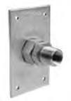
30 GUIDELINES FOR INSTALLATION OF PRO-FLEX & FLAK JACKET TM CSST FLEXIBLE GAS PIPING IN OUTDOOR APPLICATIONS [INCLUDING CORROSIVE ENVIRONMENTS] Pro-Flex & Flak Jacket TM tubing and fittings meet all performance requirements for outdoor applications and comply with the ANSI LC1 / CSA 6.26 standard. The following guidelines apply to both Pro-Flex & Flak Jacket TM CSST when installed outdoors or in other corrosive environments [including but not limited to: crawlspaces, pool mechanical rooms, and etc.] In outdoor applications, the external jacket should not be removed. All exposed tubing on the outside of a structure or located between the ground and a 6 ft height must be protected in a sealed conduit or weather-tight chase which is routed and secured to avoid mechanical damage. Any exposed stainless steel is to be wrapped with self bonding silicone tape [PFRT-50P]. When buried underground or encased in cement (slabs, foundations, etc.) the tubing must be routed within a non-metallic watertight conduit. This non-metallic conduit is to have an inside diameter 1/2 inch larger than the CSST's outer diameter. Exposed conduit ends must be sealed to prevent entry of water and debris. Local code authority will always take precedence. Therefore make sure you check with your local building authority or code authority having jurisdiction. 4.5 Meter Hookups Gas meters are generally supported by the building structure or by framework brackets independent of the structure. Do not use Pro-Flex or Flak Jacket TM CSST as a direct connection to any meter which must be supported by the piping. On structure supported meters, accepted practice is to connect the meter outlet to a stub-out or termination plate mounted on the exterior wall or to penetrate the exterior wall with a steel pipe and provide a rigid attachment for the meter and CSST tubing within the building. 26
31 On independently supported meters, CSST can, in some locations, be routed through the exterior wall and connected directly to the meter. Direct connections must provide a loop or slack in the tubing to account for building settling and meter movement. Wall penetration must be properly sealed following local code guidelines. NOTE: Building codes vary from area to area. Check with your local utility and building codes to verify that meter connections are acceptable Always remember, local jurisdiction will prevail. Note: Prior to installing flexible gas piping by Pro-Flex directly to a meter, ensure that the local utility allows this practice as some utilities have regulations specifying meter attachments. Any exposed sections of stainless steel piping must be wrapped with a silicone self-bonding tape. This is especially important with masonry and wood frame construction. 27
![4.6 Appliance Connections Fixed Appliances: Pro-Flex & Flak Jacket TM CSST may be connected directly to fixed [non-movable] appliances such as water heaters, furnaces, boilers, and island cook-tops](/docs-images/73/68870517/images/32-0.jpg "without the installation of a termination outlet or flexible appliance connector, if local code allows. All local codes requiring drig legs and shut-off valves must be observed.")
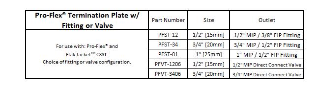
32 4.6 Appliance Connections Fixed Appliances: Pro-Flex & Flak Jacket TM CSST may be connected directly to fixed [non-movable] appliances such as water heaters, furnaces, boilers, and island cook-tops without the installation of a termination outlet or flexible appliance connector, if local code allows. All local codes requiring drig legs and shut-off valves must be observed. When appliances such as water heaters, furnaces, etc. have metallic vents which protrude through the roof physical contact between the CSST and the appliance cabinet are prohibited. appliance shut-off valve drip leg / sediment trap if required by code union [if required by code] Moveable Appliances: Termination Outlets: APro-Flex termination outlet eliminates the need for concealed fittings by allowing CSST to be routed to the exterior of a wall or floor to provide a fixed connection point (stub-out). This fixed connection point allows for the attachment of flexible appliance connectors to moveable appliances such as dryers and ranges. PFST or PFVT Series Termination Outlet: Remove the fitting or valve body [leaving nut threaded to the plate. There will be 3-4 male threads protruding through back of plate.] Slide the tube through the back side of the nut/plate assembly. Place retainer ring in 4th valley; slide the slide ring to the retainer ring; roll the O-ring on to meet the slide ring; ensure the high temp gasket is in base of fitting/valve. Thread nut/plate onto fitting/valve until hand tight. Use a pair of wrenches to hold the nut and tighten fitting/valve additional 1/4 to 1/2 turn. Mount the plate assembly to wall or floor[see wall mounting options on next page]. 28


 until hand tight then turn additional 1/4 to 1/2 turn with an additional")
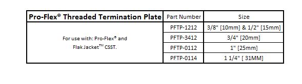
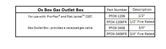
33 PFTP Series Termination Outlet: Thread male fitting body completely into PFTP Series Termination Plate. [this is easily accomplished by using a vice to hold the termination plate.] Slide nut onto CSST tubing; place retainer ring in 4th valley; slide the slide ring to the retainer ring; roll the o-ring on to meet the slide ring; ensure high temp gasket is in base of the fitting. Thread nut onto fitting/plate until hand tight. Use a pair of wrenches to hold the nut and tighten fitting additional 1/4 to 1/2 turn. Mount the plate assembly to wall or floor[see wall mounting options below]. Wall Termination Outlet Mounting Options PFST, PFVT, & PFTP Series Termination Outlets may also be mounted to the floor. PFOX Series Series Wall Box 1. Fasten Ox Box supply box directly to stud and/or on support bracket. 2. Disassemble Pro-Flex Fitting from nut. 3. Insert male threads on back of nut through hole in box and hand tighten lock nut. 4. Apply pipe thread sealant to male threads on valve. Thread into Pro-Flex Fitting and tighten. 5. Insert Pro-Flex Tubing through brass nut in bottom of box. Assemble Pro-Flex Fitting per Section 4.2 of Pro-Flex Installation / Training Guide. 6. When tightening the Pro-Flex nut to the fitting hold fitting with wrench and turn nut (it may be necessary to loosen lock nut) until hand tight then turn additional 1/4 to 1/2 turn with an additional wrench. 7. Tighten lock nut. 8. Check all connections for leaks using leak detector. 9. Turn off gas supply and connect appliance according to manufacturer's instructions using an approved appliance connector. The PFOX Series Wall Box also includes an adapter for use with rigid pipe or other CSST brands. See detailed instructions included in packaging. 29

34 Gas Fireplace Installations Pro-Flex & Flak Jacket TM CSST SHALL NOT BE routed directly into a metallic fireplace enclosure that utilizes a metallic vent that penetrates the structure's roof. The connection shall be made outside the firebox utilizing rigid pipe, a stub-out, or a termination fitting. Where it is necessary to install Pro-Flex or Flak Jacket TM through masonry materials in fireplace construction, the plastic jacket shall remain intact and the tubing should be routed through sleeving that is appropriate for the application. Sleeving is not required through ceramic liners in decorative heat generating fireplaces. Where it is allowed to install Pro-Flex or Flak Jacket TM through sheet metal enclosures such as decorative non-vented or side wall vented gas fireplaces and vibration from fan motors could cause mechanical wear, the jacket should remain intact and the tubing should be routed or supported to prevent direct contact with the enclosure. If direct contact cannot be avoided, protections such as grommets, bushing or armor (Floppy-Flex ), self bonding tape, shrink sleeve material or a minimum of four (4) wraps of #10 Mil Duct- Tape should be used. This is to ensure no physical contact will be made between the metal and the CSST tubing that would cause mechanical wear. Note: Remove jacket only on the length of CSST that may be exposed to the flame within the firebox. For Log Lighter installations in all-fuel fireplaces, the CSST SHALL BE terminated at the keyed valve or another point prior to entering the firebox. NOTE: In some configurations, the corrugated tubing (CSST) feeding gas logs or gas fireplaces can cause a humming or whistle sound. This is due to the gas flow velocity and can usually be prevented by choosing a larger piping size in accordance with the chart below. No Physical Contact No physical contact Grommet Suggested Maximum Capacity for Gas/Log Fireplace TUBING SIZE 3/8" (10 mm) 1/2" (15mm) 3/4" (20mm) FLOW [1,000 BTU's] Outdoor Gas Appliance Installations Deck Mounted Gas Appliances FIGURE 4-32 Elevated deck a fixed Pedestal mount grill or gas light - direct connection BBQ Grills and Gas Lights [as well as other outdoor appliances] that are permanently mounted to decks shall be connected to the flexible gas piping system [Pro-Flex or Flak Jacket TM CSST] as shown in Figure 4-32 and in conjunction with this guide. The outdoor sections of the CSST shall be supported and protected against any of the inside deck joists. Any tubing that is not protected, must be protected in a conduit or chase. 30

![enclosed instructions. [Figure 4-33], Striker Plates SNMarul_t_ tor!](/docs-images/73/68870517/images/35-1.jpg "nclotun MounllrQ Sid QM conntdl--- Figure 4-33 Quick Disconnect Post-Mounted Gas Appliances Post-Mounted gas appliances such as gas lights or BBQ Grills may be connected to Pro-Flex's gas")
35 Moveable Outdoor Gas Appliances BBQ Grills, Deck Heaters and other moveable outdoor appliances shall be connected to an approved outdoor appliance connector transitioning to the CSST utilizing either a termination outlet, or a quick disconnect outlet such as Pro-Flex BBQ Kit [manufactured by MB Sturgis] - the quick connect shall be installed in accordance with the manufacturer's enclosed instructions. [Figure 4-33], Striker Plates SNMarul_t_ tor!nclotun MounllrQ Sid QM conntdl--- Figure 4-33 Quick Disconnect Post-Mounted Gas Appliances Post-Mounted gas appliances such as gas lights or BBQ Grills may be connected to Pro-Flex's gas piping systems as shown in Figure All underground sections are to be protected with water-tight, nonmetallic conduit. Figure


.")
 outdoor connection to roof mounted equipment Figure 4-37 Long outdoor connection to roof mounted equipment Height of elevation based on local plumbing/building code requirements")
36 Pad Mounted Outdoor Gas Appliances FIGURE 4-35 Pad mounted gas equipment such as Heat Pumps, Pad Heaters and Natural or LP Gas Generators, may be connected to a Pro-Flex Flexible Gas Piping system [Pro-Flex or Flak Jacket TM CSST] by means of a termination outlet that connects to an approved outdoor appliance connector or a rigid pipe. Direct connection is allowed when the CSST is properly protected and mounted if local code allows. Roof Top Gas Appliances Roof Mounted Equipment: FIGURE No special mechanical protection of the CSST is required for connections to roof top equipment. Whenever possible, roof penetrations shall be located within 6 ft of the equipment to be connected as shown in Figure (4-36). Long runs of tubing shall be supported with nonmetallic blocks every 4-ft. along its outdoor length, and raised above the roof a distance determined by local code/practice (4-37). Lengths of CSST which run vertically up the side of the building shall be protected in accordance with the guidelines for outdoor installations. Figure 4-36 Short (2 to 6 ft.) outdoor connection to roof mounted equipment Figure 4-37 Long outdoor connection to roof mounted equipment Height of elevation based on local plumbing/building code requirements and/or winter ice buildup. When the equipment manufacturer requires the use of a flexible connector, the CSST shall be installed in a fashion similar to that shown in Figure 4-35 Figure 4-38 Appliance termination/stub-out 32
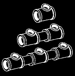
37 4.7 Manifold Stations Manifolds are installed where multiple runs are made from a common location in a parallel arrangement. The manifold may be manufactured from a one piece, malleable iron or brass casting; a welded fabrication of steel subcomponents; an assembly of approved, malleable iron tees and short nipples. Depending on the location and available space, different mounting arrangements are permitted. A manifold may be mounted on the surface of an interior wall, between open floor joists, in attic spaces, crawlspaces, within a partition wall, or inside an enclosure. The installation of manifold assemblies using a pounds-to-inches regulator must be in accordance with all local codes, and the following guidelines: 1) Standard manifold - low to medium pressure (14 w.c. or less) (Drwg A) 2) Elevated pressure manifold - A manifold assembly utilizing a pounds-to-inches regulator shall be installed in an accessible, ventilated location so that the regulator can be inspected, maintained and serviced if repair or replacement is required. (Drwg B) (Drwg A) 3) Behind access panel - For manifold systems that use a pounds-to-inches regulator installed behind an access panel, all tubing penetrations in the cabinet must be sealed, caulked or grommeted. The cabinet must be ventilated through the panel/door and not into a wall space. 4) Open face cabinets - Cabinets which communicate with the normal room environment, may be utilized without the need for ventilation or penetration sealing requirements. (Drwg B) 33
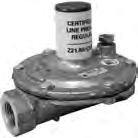
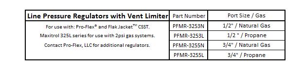
38 4.8 Pressure Regulators Description a) A gas piping system utilizing gas pressures exceeding 1/2 psi (3.45kPa), but intended to serve equipment rated for 1/2 psi (3.45 kpa) maximum, shall include a gas pressure regulator to limit the downstream supply pressure to 1/2 psi (3.45 kpa), and the installation instructions for the piping system shall specify that such a regulator shall be installed. For system pressures up to 5 psi (34.5 kpa), the regulator shall incorporate construction which will lock up under no-flow conditions to prevent excessive downstream pressure build-up. Pressure Drop from Bends and shall comply with the applicable provisions of the Standard for Line Pressure Regulators, ANSI Z21.80 CSA For system pressures above 5 psi (34.5 kpa), the regulator shall comply with a recognized national standard for pressure regulators. b) The Maxitrol 325-L Series regulators, supplied by Pro-Flex are 2 psi line pressure regulators they are used to drop the pressure from 2 psi to inches of water column. Contact Pro-Flex, LLC for additional regulator options manufactured by Maxitrol. They can also be used as a line regulator on equipment already fitted with an appliance regulator. c) The materials of all component parts are carefully selected and corrosion resistant. The housings are made of durable die cast aluminum, the diaphragm and self-aligning valve seat are made of nitrile rubber which is selected to work at ambient temperatures of -40 to 205 degrees F (-40 to 96 degrees C). All regulators are supplied with vent limiting devices that are made of brass and threaded with a type 0 (NPT Thread). Sizing Instructions a) Line Pressure Regulator Selection The Maxitrol 325-L Series Regulator is used in a 2 PSI gas piping installation to reduce supply pressure to the appliance within required operating ranges (typically 4-7 WC. natural gas or LP gas). To select the correct regulator for pressure regulation, the following information must be established; Available inlet pressure range at the regulator inlet Desired outlet pressure Required maximum flow rate Refer to tables (below) to select the correct regulator to satisfy system requirements. 34
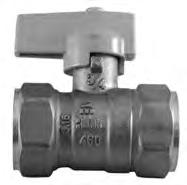
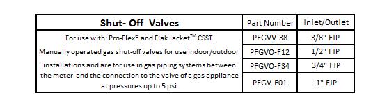
39 Installation a) The regulator shall be installed in an accessible location with an approved shut-off valve on the inlet side and a union on the outlet side so that it may be inspected, maintained and serviced if repair or replacement is required. b) The regulator is suitable for multi-poise mounting. When using a vent-limiting device however, the regulator must be mounted in a horizontal upright position. All regulators provided by Pro-Flex include a vent limiting device. c) The vent limiter is a fail-safe device that permits free air movement above the diaphragm during normal operation. In the unlikely event of a diaphragm rupture, the vent limiting device will limit gas escapement to 1.0 CFH natural gas at 2 PSI and 0.65 CFH LP at 2 PSI. Both values are below the ANSI standard of 2.5 CFH. Note: The vent-limiting device does not allow gas to escape to the environment during normal mode operation. d) Do not leak test the vent limiter with liquid leak test solution. This action will contaminate the internal ball check mechanism or plug the breathing hole resulting in erratic regulator performance e) Using a vent limiter, the maximum inlet pressure is 2 PSI. FIGURE A f) When using a vent line, the line must be at least the same size as the regulator vent connection, and cannot exceed a length of 30 ft. The vent shall be designed to prevent entry of water, insects or other foreign materials that could cause blockage of the line.. Do not vent to appliance flue, pilot light or building exhaust system. g) Maxitrol regulators have a lower temperature limit of -40 degrees F. The lower temperature limit and rust proof construction design enables the regulator to be used for outdoor installations. To minimize the potential for moisture condensation and freezing problems in or around the vent port, the vent limiting device must be removed for outdoor installations and mounted upside down. Outdoor Mounting Options: The regulator may be mounted upside down with the open vent port facing down. Consideration must be taken to ensure there is adequate clearance for snow buildup. FIGURE C FIGURE B The regulator may be mounted horizontally, with a vent tube installed in the venting port. The end of the tube must be facing downward, and should be designed to prevent water and foreign material from causing a blockage. 35
40 Line Regulator Capacity Tables Natural Gas Maxitrol Pressure Drop Table Pressure Drop sp gr gas expressed in CFH (m 3 /h) Model Number 7.0" W.C. (17 mbar) 1/2 psi (34 mbar) 3/4 psi (52 mbar) 1 psi (69 mbar) 325-3L 145 (4.0) 204 (5.8) 250 (7.0) 289 (8.2) L 338 (9.6) 476 (13.5) 583 (16.5) 673 (19.1) Capacity value for most typical 2 PSI parallel systems when trunk run is sized for 1 PSI pressure drop and a 3/4 PSI drop across regulator Propane Maxitrol Pressure Drop Table Pressure Drop sp gr gas expressed in MBTUH LP Model Number 7.0" W.C. (17 mbar) 1/2 psi (34 mbar) 3/4 psi (52 mbar) 1 psi (69 mbar) 325-3L 234 (6.4) 328 (9.3) 403 (11.3) 465 (13.2) 325-5L 544 (15.5) 766 (21.7) 939 (26.6) 1084 (30.8) Capacity value for most typical 2 PSI parallel systems when trunk run is sized for 1 PSI pressure drop and a 1/2 PSI drop across regulator Performance a) A performance test should be conducted while operating all appliances at full load. This will test if adequate pressure is reaching each appliance under full-load conditions. To accomplish this, measure the line pressure at the appliance connection while operating the appliance. b) The inlet pressure for a typical gas appliances under full load conditions should measure a minimum of 4 inches of water column pressure for natural gas and a minimum 10 inches water column pressure for propane. If these pressure ranges cannot be obtained, a slight adjustment to the service regulator or the pounds-to-inches regulator may be necessary to increase line pressure. Adjustment a) Adjustment can be accomplished by first removing the regulator seal cap to expose the adjusting screw. Turning the screw clockwise will increase outlet pressure, turning it counter-clockwise will decrease pressure. b) If spring adjustment will not produce the desired outlet pressure, check to make sure the main supply pressure is adequate. If the main supply pressure is adequate, consult factory for other line-regulator options. Do not continue to turn regulator adjusting screw clockwise if the outlet pressure readings do not continue to increase. This may result in over-firing due to loss of pressure control, should there be a subsequent increase in inlet pressure. c) The 2 PSI system pounds-to-inches regulator can be adjusted with an outlet pressure ranging between 7 to 9 inches water column pressure for natural gas and 10 to 12 inches water column for propane. The regulator must be adjusted according to the manufacturers recommended procedure. A pressure gauge mounted just downstream of the regulator can monitor the set pressure under various loads. d) The regulator outlet is pre-set and labeled at the factory for either 8 natural gas or 11 propane. e) The average natural gas appliance is designed to operate at 3 to 4 inches water column pressure, and a pressure difference of 1 to 2 inches of water column across the appliance regulator which will prevent slow regulator response. Thus, the appliance regulator will operate best at 4 to 6 inches W.C. inlet pressure. The pounds-to-inches system regulators for natural gas are set to deliver 8 inches of W.C. outlet pressure under load to allow for 3 inches of W.C. pressure drop in the tubing. f) The average propane gas appliance is designed to operate at 10 to 10-1/2 inches water column pressure. Thus, the pounds-to-inches regulators for propane gas are set to deliver 11 inches water column outlet pressure under load to allow for 0.5 inches water column pressure drop in the tubing. g) Contact Pro-Flex, LLC for availability of additional regulator sizes and configurations [including 5 psi w/ OPD]. 36
41 4.10 Electrical Bonding Per the 2009 or later versions of national model codes [NFPA-54 (National Fuel Gas Code), the Uniform Plumbing Code (UPC), and the International Fuel Gas Code (IFGC)], any gas piping system containing at least one segment of non-conductive (Yellow) coated CSST must be bonded to the buildings electrical grounding electrode system. Pro-Flex strongly recommends the equipotential bonding of all metallic mechanical systems to the structure's grounding electrode. Bonding serves to protect people and equipment in the event of an electrical event. All CSST manufactured by Pro-Flex, LLC shall be bonded in accordance with the national model codes and these instructions. If there is an inconsistency between these instructions and local codes, the local codes shall control There are no additional bonding requirements for Flak Jacket TM CSST set forth in the manufacturer s written instructions. Flak Jacket TM CSST is to be bonded in accordance with the National Electric Code NFPA 70 section (B) in the same approach as the minimum requirements for rigid metal piping. However, installers must follow any local code requirements that are more stringent than the manufacturer s written instructions. Flak Jacket TM CSST shall not be painted, otherwise coated or have labels applied. Neither Flak Jacket TM nor Pro-Flex CSST flexible gas piping are to be used as a grounding conductor or electrode for an electrical system. When Direct Bonding is Required by Local Code or Manufacturer's Requirement: a) Yellow jacketed Pro-Flex CSST must be bonded in accordance with this section. b) The bonding must be performed by a qualified person recognized by the local jurisdiction [AHJ] as capable of performing such work. c) A single bonding clamp that is listed to UL 467 is to be attached to EITHER a CSST Fitting OR a rigid pipe or rigid component at any point in the gas piping system downstream of the gas meter or second stage regulator in an accessible location. d) The bonding conductor [wire] is to be solid or stranded 6 AWG copper [minimum] or equivalent an not to exceed 75 feet in length. The effectiveness of the bond will be improved utilizing the shortest practical conductor [wire] length. e) The bonding conductor [wire] is to be directly and permanently connected to the electrical service grounding system. This can be achieved through a connection to the ground buss in the electrical service enclosure, the grounding electrode conductor, or the grounding electrode used. All grounding electrodes used shall be bonded to the electrical service grounding electrode, or if available, the lightning protection grounding system. f) The bonding shall be done in accordance with NFPA-70 [the National Electric Code] or CSA- C22.1 [the Canadian Electric Code]. g) CSST shall not be directly supported on or by other electrically conductive systems including metallic water pipe, electric power or communications cables, HVAC ducts or plenum, and structural steel beams or framing. h) A daisy chain configuration may be used to bond multiple gas services [meters] that are located within a single structure. 37


42 BONDING WIRE BONDING CLAMP Bonding Clamp Placement on CSST Fitting CSST FITTING. BONDING CLAMP BONDING WIRE Bonding Clamp Placement on Rigid Pipe Component BLACK PIPE COMPONENT OR CSST STUB-OUT Depending upon conditions specific to the location of the structure in which the flexible gas piping system is being installed, including but not limited to whether the area is prone to lightning activity, the owner of the structure should consider whether a lightning protection system is necessary or appropriate. Lightning protections are beyond the scope of this guide, see NFPA 780, the Standard for the Installation of Lightning Protection Systems, and other standards. Failure to properly bond Pro-Flex flexible gas piping systems in accordance with NFPA 70 [NEC] may lead to damage to the CSST system in the event of a lightning strike. Proper bonding will help reduce the possibility and/or severity of arcing between conductive systems when energized by a nearby lightning strike. 38

43 5.0 Inspection and Testing of Installed CSST Pressure Testing and Inspection Procedure a) The final installation must be inspected and tested for leaks in accordance with the local / state codes. In the absence of local restrictions test in accordance with the procedures specified in Part 4 of the National Fuel Gas Code, ANSI Z223.1 / NFPA 54, and/or the Natural Gas and Propane Installation Code, CSA B149.1 & B149.2, or the International Fuel Gas Code, or in accordance with the requirements of the applicable local codes. The installed gas piping system shall not exhibit any loss of pressure during the field pressure test. When local codes are more stringent, local codes must be followed. Note: Remove or isolate the pound-to-inches pressure regulator for system pressure test. Subjecting the regulator to pressures greater than 10 PSI could damage the regulator and will not expose the downstream tubing to the correct test pressure. b) Pressure testing must be performed during rough construction of the facility (before interior walls are finished). This will permit a more complete inspection of the piping system during the pres-sure testing. c) Do not connect appliances or pressurize with fuel gas until after the pressure test has been performed. d) All gas outlets for appliance connections should be capped during pressure testing. e) A 2 PSI system usually requires a pressure test of 10 PSI or greater, depending on local code. In this case, the regulator must be removed or isolated prior to pressure testing. The test may be performed as a onepart test replacing the regulator with suitable jumper pipe length for pressure testing the entire system. Or a two-part test may be performed as shown in figure below. The first test is performed on the elevated pressure section, between the meter connection and the pounds-to-inches house line regulator. The second test is performed on the low-pressure section, between the outlet of the pounds-to-inches house line regulator and the gas appliance outlets. For a two-part test, it is important to remember to close both gas shut-off valves to avoid damage to the regulator. f) Electrical bonding must be in place as described on pages Electrical Bonding. 39
44 g) Most jurisdictions also require an additional pressure or leakage test performed after the construction is completed and finished interior walls are in place. The leakage test procedure is generally performed by the gas utility at the time of setting their meter. This test is performed to assure no damage was done to the tubing during the closing-in construction process, and is typically required before gas service is initiated. Appliance Connection Leakage Check Procedure After the final pressure test, inspection and final construction is complete (finished interior walls) connect the appliances to the tubing system. This connection is made using approved stainless steel flexible connectors for movable appliances such as a dryer or range, or with CSST tubing, or rigid black pipe for fixed appliances. Turn the gas on at the meter and inspect for leakage before operating the appliances. a) Connections made at the appliances should be leak checked with a chloride-free bubble solution. b) Before placing the appliances in operation, the tubing system should be purged. This displaces the air in the system with fuel gas. Be sure to vent into a well-ventilated area. NOTE: Leak test solutions may cause corrosion to some types of material in the gas tubing system, be sure to water rinse after the test and thor-oughly dry all contacted material. Also, the vent limiter should not be leak tested with a liquid test solution. This will contaminate the internal ball check mechanism or plug the breathing hole, resulting in erratic regulator operation. 40
45 5.1 Repair and Replacement of Damaged CSST REPAIRING DAMAGED CSST TUBING & FITTINGS Repair Classifications: FITTINGS: Leaking fittings should be repaired in accordance with the manufacturers installation instructions. In some cases, the entire fitting or parts of the fitting must be replaced totally. CSST TUBING: If the tubing is damaged, the severity of damage and if necessary, the method of repair shall be determined as follows: a. Tubing shall be repaired if damaged due to a puncture of any kind from nails, screws or drill bits. b. Tubing shall be repaired if significantly damaged due to impact or crushing as indicated in Figure c. Tubing shall be repaired if bent beyond its minimum bend radius and there is a crease or kink in the tubing. (See Figure 4-45) d. No repairs or replacements of tubing is necessary if the tubing is only slightly dented due to minor impact or crushing. (See Figure 4-46) 41

46 METHODS OF REPAIR There are different methods of repair which are discussed below depending on the nature and severity of the damage. The Installer must determine the most reliable and economical method of repair using one of the following methods. Replace the entire tubing run. When the tubing run is short and easily accessible, it can be repaired faster and more economically by replacing the whole run versus repairing only the damaged section. Replacement in this instance is the preferred method because extra fittings are not required. Repairing damaged section. Damaged tubing shall be repaired by methods listed below. a. Remove the section of tubing which is damaged and connect the new ends with a union fitting as shown in Figure 4-47 Use this repair method if the damage section is small and there is enough slack tubing in the run to makeup the damaged length. Typical Tubing Splice with Union Fitting FIGURE 4-47 Repair of Damaged Jacket - Flak Jacket TM A repair is required if the Flak Jacket TM jacket material has been torn, cut, ripped, or exposed to an electrical arc. The jacket shall be wrapped around its circumference using self-bonding silicone tape [such as Pro- Flex part PFRT-50P], covering the entire damaged area. No exposed stainless steel is permitted [this includes at the junctions of fittings and tubing]. 42
Installation/Training Guide PRO-FLEX CSST
 TRU-FLEX METAL HOSE CORP. is an ISO Registered Company Installation/Training Guide PRO-FLEX CSST Patented System #5,845,946, #5,857,716 & #6,102,445 and other patents pending 2391 S. St. Rd. 263 PO Box
DESIGN AND INSTALLATION GUIDE
 DESIGN AND INSTALLATION GUIDE CORRUGATED STAINLESS STEEL TUBING FUEL GAS* PIPING *Includes Natural Gas and Propane P.O. BOX 9 BLOSSBURG, PA. 16912 570 638-2131 WWW.WARDFLEX.COM C US THROUGH-PENETRATION
DESIGN AND INSTALLATION GUIDE
 DESIGN AND INSTALLATION GUIDE FOR CORRUGATED STAINLESS STEEL TUBING FUEL GAS* PIPING *Includes Natural Gas and Propane P.O. BOX 9 BLOSSBURG, PA. 16912 570 638-2131 www.wardflex.com C US THROUGH-PENETRATION
2009 DESIGN & INSTALLATION GUIDE
 2009 DESIGN & INSTALLATION GUIDE June 2009 DESIGN AND INSTALLATION GUIDE FOR CORRUGATED STAINLESS STEEL TUBING FUEL GAS* PIPING *Includes Natural Gas and Propane P.O. BOX 9 BLOSSBURG, PA. 16912 570 638-2131
2014 DESIGN & INSTALLATION GUIDE
 2014 DESIGN & INSTALLATION GUIDE WFDI-072014 JULY, 2014 www.wardmfg.com (800) 248-1027 DESIGN AND INSTALLATION GUIDE CORRUGATED STAINLESS STEEL TUBING FUEL GAS* PIPING * Includes Natural Gas and Propane
Page 1 of 18 Gastite Quiz Part 2
 garyklinka@hotmail.com Page 1 of 18 Gastite Quiz Part 2 Instructions Fees: 1hr $15 or 4 hrs. $40 or 12 hrs. $100 1. Print these pages and Click Here for the necessary Gastite reference materials. 2. Answer
DESIGN GUIDE & INSTALLATION INSTRUCTION MANUAL
 DESIGN GUIDE & INSTALLATION INSTRUCTION MANUAL TECVALCO LTD. 3481 STANLEY AVE. RR#1 NIAGARA FALLS, ON L2J 0E4 TABLE OF CONTENTS 1.0 Introduction... 5 User Warnings Limitations of Manual DIAMONDBACK Applications
SIZING AND CAPACITIES OF GAS PIPING
 APPENDIX A (IFGS) SIZING AND CAPACITIES OF GAS PIPING (This appendix is adopted as part of the code.) A.1 General. To determine the size of piping used in a gas piping system, the following factors must
SIZING AND CAPACITIES OF GAS PIPING
 APPENDIX A (IFGS) SIZING AND CAPACITIES OF GAS PIPING (This appendix is informative and is not part of the code. This appendix is an excerpt from the 2003 International Fuel Gas Code, coordinated with
SIZING AND CAPACITIES OF GAS PIPING
 SIZING AND CAPACITIES OF GAS PIPING A.1 General piping considerations. The first goal of determining the pipe sizing for a fuel gas piping system is to make sure that there is sufficient gas pressure at
SIZING AND CAPACITIES OF GAS PIPING
 (IFGS) SIZING AND CAPACITIES OF GAS PIPING (This appendix is informative and is not part of the code. This appendix is an excerpt from the 2006 International Fuel Gas Code, coordinated with the section
AVAILABLE IN NUMEROUS LENGTHS INCLUDING 25 FT TRADITIONAL YELLOW OR BLACK ARC-RESISTANT JACKETS THE ONE-STOP SHOP FOR YOUR ROUGH-IN GAS PRODUCTS!
 FLEXIBLE STAINLESS STEEL GAS TUBING FOR USE WITH NATURAL GAS OR PROPANE (LP) AVAILABLE IN NUMEROUS LENGTHS INCLUDING 25 FT TRADITIONAL YELLOW OR BLACK ARC-RESISTANT JACKETS THE ONE-STOP SHOP FOR YOUR ROUGH-IN
IAPMO GUIDE CRITERIA FOR BALL VALVES IAPMO IGC PURPOSE
 INTERNATIONAL ASSOCIATION OF PLUMBING AND MECHANICAL OFFICIALS IAPMO GUIDE CRITERIA FOR BALL VALVES IAPMO IGC 157-20067 1 PURPOSE 1.1 The purpose of this standard is to establish an acceptable standard
SIZING AND CAPACITIES OF GAS PIPING Reserved
 APPENDIX A (IFGS) SIZING AND CAPACITIES OF GAS PIPING Reserved 2003 INTERNATIONAL RESIDENTIAL CODE 529R APPENDIX A SIZING AND CAPACITIES OF GAS PIPING This page left intentionally blank. 530R 2003 INTERNATIONAL
SPECIFICATION SHEET. OMEGAFLEX, Ltd. TracPipe Flexible Gas Piping Specification Sheet Specification date. ProjectName
 OMEGAFLEX, Ltd. TracPipe Flexible Gas Piping Specification Sheet Specification date ProjectName Model Number(s) - FGP-SS4-50 FGP-SS4-40 FGP-SS4-32 FGP-SS4-28 FGP-SS4-22 FGP-SS4-15 FGP-SS4-12 Note: This
G196 Series BASOTROL Redundant Combination Gas Valve with Manual Shutoff Valve
 Installation Instructions Issue Date March 13, 2013 G196 Series BASOTROL Redundant Combination Gas Valve with Manual Shutoff Valve Application The G196 valves are suitable for use with natural gas, Liquefied
G196 Series BASOTROL Redundant Combination Gas Valve with Manual Shutoff Valve
 Installation Instructions Issue Date August 19, 2008 G196 Series BASOTROL Redundant Combination Gas Valve with Manual Shutoff Valve Application The G196 valves are suitable for use with natural gas, Liquefied
GAS SUPPLY DESIGN GUIDE
 GAS SUPPLY DESIGN GUIDE Natural Gas, Propane Gas, or Dual Fuel Fired Modulating, Condensing Boilers BENCHMARK Series Gas-Fired Boilers For models: BMK750 to BMK6000 Last Update: 06/20/2014 PR1 06/20/14
ACCESSORY KIT INSTALLATION INSTRUCTIONS
 ACCESSORY KIT INSTALLATION INSTRUCTIONS 1NP0680 - PROPANE CONVERSION FOR USE WITH MODELS: PM8, PC8, PM9, PC9, FL9M, FL9C, FC9M, FC9C This conversion kit is to be installed by a qualified service agency
INSTRUCTIONS FOR CONVERTING CONDENSING GAS MOBILE HOME FURNACES MODEL SERIES: CMA3*, CMC1*, VMA3*, VMC1*
 INSTRUCTIONS FOR CONVERTING CONDENSING GAS MOBILE HOME FURNACES MODEL SERIES: CMA3*, CMC1*, VMA3*, VMC1* THIS KIT CONTAINS: AOPS7741 (NATURAL TO PROPANE CONVERSION PARTS FOR MODEL SIZE, 50) AOPS7742(NATURAL
BGA158 Series CE Approved Class A Shutoff Gas Valve
 Installation Instructions BGA158 Issue Date August 24, 2011 BGA158 Series CE Approved Class A Shutoff Gas Valve Applications The BGA158 Series shutoff gas valve is an electrically operated gas valve that
GAS DELIVERY PRESSURE AND MEASUREMENT
 GAS DELIVERY PRESSURE AND MEASUREMENT I. PURPOSE: To establish a uniform basis on which to provide gas measurement and pressure regulation facilities on customers premises. II. DELIVERY PRESSURES AND PROVISIONS:
GAS SUPPLY APPLICATION GUIDE
 GAS SUPPLY APPLICATION GUIDE Natural Gas or Propane Modulating & Condensing Boilers and Water Heaters This document applies to the following models: Boilers AM 399B AM 500B AM 750B AM 1000B Gas-Fired Boilers
G96 Series BASOTROL Dual Operator Valve
 Installation Instructions 9. Issue Date February 22, 2013 G96 Series BASOTROL Dual Operator Valve Applications The G96 valves are combination, dual operator, automatic valves available with or without
Your safety and the safety of others are very important.
 NATURAL GAS TO PROPANE CONVERSION KIT ALPKT57- INSTALLATION INSTRUCTIONS PROPANE CONVERSION KIT SAFETY... INSTALLATION REQUIREMENTS... Tools and Parts... LP Gas Requirements... Table of Contents INSTALLATION
Installation Instructions
 48011HW NATURAL GAS TO PROPANE CONVERSION KIT 58HDX, 359AAV, PG9YAB, PG9YAA Installation Instructions SAFETY REQUIREMENTS Installing and servicing heating equipment can be hazardous due to gas and electrical
BGA158 Series CE Approved Class B Shutoff Gas Valve
 Installation Instructions BGA158 Issue Date March 22, 2016 BGA158 Series CE Approved Class B Shutoff Gas Valve Applications The BGA158 Series shutoff gas valve is an electrically operated shutoff valve
Type S301 & S302 Gas Regulators INTRODUCTION INSTALLATION. Scope of Manual. Description. Specifications. Type S301 and S302. Instruction Manual
 Fisher Controls Instruction Manual Type S301 & S302 Gas Regulators October 1981 Form 5180 WARNING Fisher regulators must be installed, operated, and maintained in accordance with federal, state, and local
Natural Gas Conversion Kit
 SERIAL #: Attention: Centro recommends that a qualified gas technician perform the gas supply conversion and orifice replacement for this BBQ model. Natural Gas Conversion Kit F O R U S E W I T H M O D
For use with select HPC Fire Pits ONLY- refer to product catalog or website. 100K BTU Maximum WARNING: FOR OUTDOOR USE ONLY
 For use with select HPC Fire Pits ONLY- refer to product catalog or website. 100K BTU Maximum : FOR OUTDOOR USE ONLY Small Tank LP Kit (STLPK) Installation & Operation Instructions Installation We suggest
Check with local zoning official for property line distance requirements.
 RESIDENTIAL POOL PLAN SUBMITTAL GUIDELINES The following guidelines are intended to assist municipal residents with the permit acquisition process with regard to pools, spas and hot tubs for single family
1 Exam Prep NFPA 99 Health Care Facilities Questions and Answers (Plumbing Contractor)
") 1 Exam Prep NFPA 99 Health Care Facilities Questions and Answers (Plumbing Contractor) 1. According to NFPA 99, SCFM is an acronym for. a) Surface Conditions at Fahrenheit Mercury b) Standard Conditions
1 Exam Prep NFPA 99 Health Care Facilities Questions and Answers (Plumbing Contractor) 1. According to NFPA 99, SCFM is an acronym for. a) Surface Conditions at Fahrenheit Mercury b) Standard Conditions
Natural Gas High-Altitude Conversion Kit For Installations in the United States (2,001 10,000 Feet)
") Natural Gas High-Altitude Conversion Kit For Installations in the United States (2,001 10,000 Feet) INSTALLATION INSTRUCTIONS For R7 Series Light Commercial Packaged Gas Electric Units IIMPORTANT: Please
Natural Gas High-Altitude Conversion Kit For Installations in the United States (2,001 10,000 Feet) INSTALLATION INSTRUCTIONS For R7 Series Light Commercial Packaged Gas Electric Units IIMPORTANT: Please
INSTALLATION INSTRUCTIONS MANUAL ON/OFF SAFETY VALVE/PILOT KIT MODEL GA9050A-1 (F0235)
") P/N 126905-01 Rev. B 11/2016 INSTALLATION INSTRUCTIONS MANUAL ON/OFF SAFETY VALVE/PILOT KIT MODEL GA9050A-1 (F0235) For All Single, Dual and Triple Burner Natural and Propane/LP Gas Logs P126905-01 For
P/N 126905-01 Rev. B 11/2016 INSTALLATION INSTRUCTIONS MANUAL ON/OFF SAFETY VALVE/PILOT KIT MODEL GA9050A-1 (F0235) For All Single, Dual and Triple Burner Natural and Propane/LP Gas Logs P126905-01 For
G92 Series BASOTROL Automatic Pilot Gas Valve
 Installation Instructions Issue Date September 17, 2008 G92 Series BASOTROL Automatic Pilot Gas Valve Installation IMPORTANT: Only qualified personnel should install or service BASO Gas Products. These
Types 749B and R130 Changeover Manifolds
 Instruction Manual MCK-1179 Types 749B and R130 June 2012 Types 749B and R130 Changeover Manifolds TYPE HSRL-749B TYPE 64SR/122 TYPE R130/21 TYPE 749B/21 Figure 1. Changeover Manifolds and Regulator Assemblies
BGA158, BGA171 and BGA110 Series Shutoff Gas Valve
 Installation Instructions BGA Series Issue Date October 3, 2017 BGA158, BGA171 and BGA110 Series Shutoff Gas Valve Applications The BGA Series shutoff gas valve is an electrically operated gas valve that
Dual Solenoid Gas Valve Installation
 Installation IMPORTANT: These instructions are intended as a guide for qualified personnel installing or servicing FLYNN Gas Products. Carefully follow all instructions in this bulletin and all instructions
INSTALLATION, OPERATION AND MAINTENANCE GUIDE
 INSTALLATION, OPERATION AND Placement in Pipeline System When installing Process Development & Control s ElastoTITE Elastomer-Hinged Check Valves in a pipeline, a minimum of five pipe diameters should
Natural Gas to L.P. Gas Conversion Kit
 Natural Gas to L.P. Gas Conversion Kit For Bosch 96% AFUE Gas Furnace, BGH96 Model Installation Instructions 3124627 2 Natural Gas to L.P. Gas Conversion Kit Installation Instructions Data subject to change
WARNING: FOR OUTDOOR USE ONLY
 Certified to CSA International 4.96 US For Outdoor Gas Fireplaces A HIGHER STANDARD IN QUALITY AND APPEARANCE SAFE AND BEAUTIFUL OUTDOOR LARGO FIRE PIT FOR PROPANE AND *NATURAL GAS OWNER S MANUAL WARNING:
ACCESSORY KIT INSTALLATION MANUAL
 ACCESSORY KIT INSTALLATION MANUAL LP (PROPANE) CONVERSION KIT 1NP0366 FOR USE WITH MODELS: G8C & GF8 This conversion kit shall be installed by a qualified service agency in accordance with these instructions
SUMMITTM 400 & 600. Natural Gas Barbecues. Step-By-Step Guide
 SUMMITTM 400 & 600 Natural Gas Barbecues Step-By-Step Guide W E B E R W E B E R W E B E R W E B E R Summit 400 NG Summit 600 NG CANADIAN GAS ASSOCIATION R A P P R O V E D WARNING: Follow all leak check
FLAMMABLE GASES AND FLAMMABLE CRYOGENIC FLUIDS
 CHAPTER 35 FLAMMABLE GASES AND FLAMMABLE CRYOGENIC FLUIDS SECTION 3501 GENERAL 3501.1 Scope. The storage and use of flammable gases shall be in accordance with this chapter. Compressed gases shall also
V-24 OXYGEN LANCE VALVE
 INSTRUCTIONS for F-4737-U May, 2009 V-24 OXYGEN LANCE VALVE w/ C -Size Inlet w/ B -Size Inlet V-24 Oxygen Lance with 1/8" Pipe Holder... 9728D65... 2218939 V-24 Oxygen Lance with 1/4" Pipe Holder... 9728A65...
36G22, 36G23, 36G24 & 36G52 36J22, 36J23, 36J24 & 36J52 DSI and HSI Single Stage Combination Gas Valve
 Operator: Save these instructions for future use! FAILURE TO READ AND FOLLOW ALL INSTRUCTIONS CAREFULLY BEFORE INSTALLING OR OPERATING THIS CONTROL COULD CAUSE PERSONAL INJURY AND/OR PROPERTY DAMAGE. DESCRIPTION
GAS DISTRIBUTION PRODUCTS TRANSITION FITTINGS
 GAS DISTRIBUTION PRODUCTS TRANSITION FITTINGS CONTINENTAL INDUSTRIES, INC. The Ultimate Connection CONTINENTAL INDUSTRIES, INC. ABOUT US THE ULTIMATE CONNECTION Our Company Continental Industries, Inc.,
Natural Gas to L.P. Gas Conversion Kit
 Natural Gas to L.P. Gas Conversion Kit For Bosch 80% AFUE Gas Furnace, BGS80 Model Installation Instructions 3124627 2 Natural Gas to L.P. Gas Conversion Kit Installation Instructions Data subject to change
Continental Industries TRANSITION FITTINGS or FAX Visit
 Continental Industries TRANSITION FITTINGS 1-800-558-1373 or FAX 1-800-788-1668 Visit www.conind.com ABOUT US Our Company Continental Industries, headquartered in Tulsa, Oklahoma, was formed in 1958 and
S300 Series. Valve Link. Features. Fisher Controls
 S0 Series Self-Operated Type VL FIELDVUE Regulators Valve Link Fisher Controls May 198 Bulletin 71.1:S0 The S0 Series self-operated, spring-loaded regulators are used for pressure-reducing control in a
Certified LP/Propane Line Pressure Regulator Guidebook
 3rd Edition Certified LP/Propane Line Pressure Regulator Guidebook 2 & 5 PSI Systems 2 3 The specifications in this Handbook refer to Maxitrol line pressure regulators used in LP/Propane applications only.
KC Series Gas Components and Supply Design Guide
 Technical Bulletin KC Series Gas Components and Supply Design Guide GF-1030 General AERCO KC Series gas fired potable water heaters and boilers are modulating input devices that require an adequate volume
Operator: Save these instructions for future use!
 INLET PRESS TAP WHITE-RODGERS 36E93-304 Delay-Opening Combination Gas Valve INSTALLATION INSTRUCTIONS Operator: Save these instructions for future use! FAILURE TO READ AND FOLLOW ALL INSTRUCTIONS CAREFULLY
PARTS, SERVICE & REPAIR BULLETIN
 WH4C PARTS, SERVICE & REPAIR BULLETIN 400 SERIES HEAVY DUTY WELDING HANDLE Manual No: 0056-3763 Issue Date: October 07, 03 Revision: AA VictorTechnologies.com Table of Contents SECTION : GENERAL SAFETY
Model MTB-ASME Vertical Bladder Tanks
 DATA SHEET Model MTB-ASME Vertical Bladder Tanks Features n UL Listed for use with various proportioners and foam concentrates n 175 psi (12.1 bar) maximum allowable working pressure (design pressure)
Residential and Small Commercial
 Page 1 of 7 Companies Affected: NIPSCO CGV CMD CKY COH CMA CPA REFERENCE 49 CFR Part 192.353, 192.355, 192.357 1. GENERAL The purpose of this standard is to provide requirements for the inspection or installation
Horizontal Bladder Tanks
 DATA SHEET Horizontal Bladder Tanks Features UL Listed and FM Approved for use with various ANSUL proportioners and foam concentrates 175 psi (12.1 bar) maximum allowable working pressure (design pressure)
Model MTB-ASME Horizontal Bladder Tanks
 DATA SHEET Model MTB-ASME Horizontal Bladder Tanks Features n UL Listed and FM Approved for use with various proportioners and foam concentrates n 175 psi (12.1 bar) maximum allowable working pressure
Model MTB-ASME Vertical Bladder Tanks
 DATA SHEET Model MTB-ASME Vertical Bladder Tanks Features n UL Listed for use with various proportioners and foam concentrates n 175 psi (12.1 bar) maximum allowable working pressure (design pressure)
36H SERIES Combination Gas Valve
 FAILURE TO READ AND FOLLOW ALL INSTRUCTIONS CAREFULLY BEFORE INSTALLING OR OPERATING THIS CONTROL COULD CAUSE PERSONAL INJURY AND/OR PROPERTY DAMAGE. DESCRIPTION The 36H series combination gas valve is
Halsey Taylor Owners Manual STOP!
 Halsey Taylor Owners Manual 4710 Freeze Resistant Floor Mounted Steel Fountain STOP! PLEASE READ THE FOLLOWING INFORMATION. ITALLATION ITRUCTIO FOR THE 4710FR FTN. WITH 97243C SINGLE VALVE CONTROL ASSEMBLY
WARNING: Installation Instructions. Natural Gas High Altitude Conversion Kit United States Installations Only
 Natural Gas High Altitude Conversion Kit United States Installations Only Installation Instructions Light Commercial Packaged Gas Electric Units R7TQ Series 6, - 7 1/2, & 10 Ton (2,001 FT - 10,000 FT)
e G) GOVERNOR t,5 ii:i! Line Pressure Regulators
 GOVERNOR t,5 ii:i! Line Pressure Regulators") Line Pressure Regulators @ - c - e G) t,5 ii:i! 1rlr1t APPLICATION NOTES 1rlr1t A. The Governor regulator is ANSI Z21.80a and ANSI Z21.18 certified for vent limited installations (indoor installations
Line Pressure Regulators @ - c - e G) t,5 ii:i! 1rlr1t APPLICATION NOTES 1rlr1t A. The Governor regulator is ANSI Z21.80a and ANSI Z21.18 certified for vent limited installations (indoor installations
OPERATING INSTRUCTIONS AND OWNER S MANUAL READ AND FOLLOW ALL INSTRUCTIONS
 READ INSTRUCTIONS CAREFULLY: OPERATING INSTRUCTIONS AND OWNER S MANUAL Model # MH500LPT MH400PT READ AND FOLLOW ALL INSTRUCTIONS Place instructions in a safe place for future reference. Do not allow anyone
ACCESSORY KIT INSTALLATION INSTRUCTIONS
 ACCESSORY KIT INSTALLATION INSTRUCTIONS PROPANE CONVERSION - INDUCED COMBUSTION FURNACES 1NP0501 FOR USE WITH 95% MODELS: TG9S, GG9S (130,000 BTU ONLY) FOR USE WITH 80% MODELS: TG(8,L)S, GG(8,L)S (130,000
e G) GOVERNOR t,5 ii:i! Line Pressure Regulators
 GOVERNOR t,5 ii:i! Line Pressure Regulators") Line Pressure Regulators @ - c - e G) t,5 ii:i! 1rlr1t APPLICATION NOTES 1rlr1t A. The Governor regulator is ANSI Z21.80a and ANSI Z21.18 certified for vent limited installations (indoor installations
Line Pressure Regulators @ - c - e G) t,5 ii:i! 1rlr1t APPLICATION NOTES 1rlr1t A. The Governor regulator is ANSI Z21.80a and ANSI Z21.18 certified for vent limited installations (indoor installations
Vertical Bladder Tanks
 DATA SHEET Vertical Bladder Tanks Features UL Listed and FM Approved for use with various ANSUL proportioners and foam concentrates 175 psi (12.1 bar) maximum allowable working pressure (design pressure)
36E DSI, HSI & Proven Pilot Two-Stage Combination Gas Valve INSTALLATION INSTRUCTIONS
 INLET PRESS TAP WTE-RODGERS 36E96-314 DSI, HSI & Proven Pilot Two-Stage Combination Gas Valve INSTALLATION INSTRUCTIONS Operator: Save these instructions for future use! FAILURE TO READ AND FOLLOW ALL
R600 and HSRL Series Instruction Manual
 Instruction Manual MCK 2141 November 2009 R600 and HSRL Series Instruction Manual! Warning Failure to follow these instructions or to properly install and maintain this equipment could result in an explosion
Halsey Taylor Owners Manual 4410 Freeze Resistant Tubular Fountain STOP!
 Halsey Taylor Owners Manual 4410 Freeze Resistant Tubular Fountain STOP! PLEASE READ THE FOLLOWING INFORMATION. ITALLATION ITRUCTIO FOR THE 4410FR FTN. WITH 97243C SINGLE VALVE CONTROL ASSEMBLY ARE LOCATED
Service and installation must be performed by a trained/experienced service technician.
 CATALOG Service and installation must be performed by a trained/experienced service technician. All products used with combustible gas must be installed and used strictly in accordance with the instructions
GM-7000 Series CE Approved Gas Control Valve
 Installation Instructions GM-7000 Issue Date November 9, 2012 GM-7000 Series CE Approved Gas Control Valve Installation IMPORTANT: These instructions are intended as a guide for qualified personnel installing
Installation Operating Instructions for Simple Duplex Manual Manifolds PX-TSD Series
 Introduction Powerex manifolds are cleaned, tested and prepared for the indicated gas service and are built in accordance with the Compressed Gas Association guidelines. The manifold consists of a regulator
Installation Instructions For Natural Gas Conversion
 Installation Instructions For Natural Gas Conversion (Kit Part No. 1175405) This kit is designed to convert PGX4 and PX4 Two -Stage Gas units for use with Natural Gas. Table 1 Heating Value at Altitude
LINE PRESSURE REGULATOR GUIDEBOOK 7TH EDITION
 CERTIFIED LINE PRESSURE REGULATOR GUIDEBOOK 7TH EDITION 2 AND 5 PSI SYSTEMS 2 3 This Handbook contains information from national heating and plumbing ordinances or codes that may have been adopted or incorporated
R122H, R222, R232A, and R232E Series Instruction Manual
 Instruction Manual MCK 2156 R122H, R222, R232A, and R232E Series October 2012 R122H, R222, R232A, and R232E Series Instruction Manual Failure to follow these instructions or to properly install and maintain
TriPod Safety Coupler Installation & Operating Instructions for Models TP4, TP5, TP6, and TP7
 TriPod Safety Coupler Installation & Operating Instructions for Models TP4, TP5, TP6, and TP7 March 2014 Form FVC097 - Rev03 IMPORTANT: KEEP THIS DOCUMENT WITH THE PRODUCT UNTIL IT REACHES THE END USER.
36E DSI and HSI Two-Stage Combination Gas Valve INSTALLATION INSTRUCTIONS
 INLET PRESS TAP WTE-RODGERS 36E54-214 DSI and HSI Two-Stage Combination Gas Valve INSTALLATION INSTRUCTIONS Operator: Save these instructions for future use! FAILURE TO READ AND FOLLOW ALL INSTRUCTIONS
JACKSON GRILLS PATIO FIRE
 PLEASE KEEP THESE INSTRUCTIONS FOR FUTURE REFERENCE JACKSON GRILLS PATIO FIRE Tested by: Tested to: ANSI Z21.97-2010 & CSA CAN 1-2.21-M85 WARNING: For Outdoor Use Only. WARNING: If the information in this
INSTALLATION, MAINTENANCE & OPERATING INSTRUCTIONS 2-4 REDUCED PORT/ FULL PORT (5700/6700) ANSI CLASS 150/300/600/900/1500/2500 TRUNNION BALL VALVES
 ANSI CLASS 150/300/600/900/1500/2500 TRUNNION BALL VALVES") PBV-USA,Inc. 12735 Dairy Ashford. Stafford, Texas USA 77477 281-340-5400; 800-256-6193 FAX: 281-340-5499 INDUSTRIAL BALL VALVES IM0 69 April 2001 Rev 9 INSTALLATION, MAINTENANCE & OPERATING INSTRUCTIONS
PBV-USA,Inc. 12735 Dairy Ashford. Stafford, Texas USA 77477 281-340-5400; 800-256-6193 FAX: 281-340-5499 INDUSTRIAL BALL VALVES IM0 69 April 2001 Rev 9 INSTALLATION, MAINTENANCE & OPERATING INSTRUCTIONS
Design and Application Details MICRO-RATIO Valves
 Flow Control Valves Page 7003 Design and Application Details MICRO-RATIO Valves Principle of Operation MICRO-RATIO Valve assemblies typically consist of a fixed-gradient air butterfly valve mechanically
GM Series Dual-Block Multi-Function Gas Control Valves
 Installation Sheets Manual 121 Gas Combustion Combination Controls and Systems Section G Technical Bulletin GM Issue Date 0297 GM Series Dual-Block Multi-Function Gas Control Valves Figure 1: GM Series
New Hampshire Public Utilities Commission CFR 49 Part 192 Regulations. MINIMUM Pipeline Safety Regulations
 New Hampshire Public Utilities Commission CFR 49 Part 192 Regulations MINIMUM Pipeline Safety Regulations Application for Jurisdictional LPG Operators 1 Pipeline Safety Regulations 49 CFR Part 192 (NOTE:
Gas Conversion Kits CERAMIC HEATER SERIES (1, 2, 3, 4 Burner Units)
") DESCRIPTION These kits are designed to convert from one gas type to another (eg. from NATURAL to PROPANE or from PROPANE to NATURAL) only for new heaters (5 years or newer) by replacing the gas valve spring
DESCRIPTION These kits are designed to convert from one gas type to another (eg. from NATURAL to PROPANE or from PROPANE to NATURAL) only for new heaters (5 years or newer) by replacing the gas valve spring
SECTION DOMESTIC WATER PIPING
 PART 1 - GENERAL 1.1 RELATED DOCUMENTS A. Drawings and general provisions of the Contract, including General and Supplementary Conditions Specification Sections, apply to this Section. B. Related Sections
INTERLOCKED METAL HOSE
 INTERLOCKED METAL HOSE HOSE FUNDAMENTALS Penflex interlocked metal hoses are made for a variety of specialized industrial applications and are available in a wide range of metals, styles and sizes. Interlocked
MV-105 MEDIUM VOLTAGE CABLE. 5kV, 8kV, 15kV, 25kV & 35kV
 MV-05 MEDIUM VOLTAGE CABLE 5kV, 8kV, 5kV, 5kV & 5kV MV-05 MEDIUM VOLTAGE POWER CABLE 5kV % INSULATION LEVEL 8kV 00% INSULATION LEVEL Conductor conforming to ASTM B and Class B Compact stranded in accordance
6. Features & Benefits Installation Considerations Jointing Instructions Pipe Sizing Calculations & Tables
 Contents 2. Overview 3-4. Pipe 5. Fittings 6. Features & Benefits 7-13. Installation Considerations 14-16. Jointing Instructions 17-23. Pipe Sizing Calculations & Tables 24-28. Gas Plus Fitting & Tools
installation instructions
 installation instructions GAS CONVERSION KIT PROPANE-TO-NATURAL P/N 315572-71201 4GAD 6GAD Cancels: IIK 4G-50-4 IIK 4G-50-5 7/15/91 NOTE: Read the entire instructions before starting the installation.
Medical Gas Control Panel
 Medical Gas Control Panel INSTALLATION & MAINTENANCE MANUAL 255105 (Rev. 6) 2018-04 2 255105 (Rev. 6) 2018-04 1.0 User Responsibilities The information contained in this installation and operation maintenance
H15 Series BASO 100% Shutoff, Automatic Pilot Valve
 Installation Instructions Issue Date February 22, 2013 H15 Series BASO 100% Shutoff, Automatic Pilot Application The H15 Series pilot valves provide safe lighting and complete shutoff of pilot and main
MUELLER. Mega-Lite Drilling Machine. Reliable Connections. table of contents PAGE. Equipment 2. Operating Instructions 3-4. Parts Information 5
 operating Instructions manual MUELLER Mega-Lite Drilling Machine table of contents PAGE Equipment 2 Operating Instructions 3-4 Parts Information 5 Travel Charts 6-11! WARNING: 1. Read and follow instructions
SIMPLAIR PIPING TOOL. JXT Company
 SIMPLAIR PIPING INGERSOLL-RAND SIMPLAIR PIPING With push-in fittings and lightweight anodized aluminum pipe, a SimplAir system provides ideal connection throughout your entire air distribution system.
INSTALLATION AND OPERATION INSTRUCTIONS
 INSTALLATION AND OPERATION INSTRUCTIONS Liquid propane units are designed and certified for use, only with household liquid propane supply. Do not use " portable " propane tanks of less than 20-lbs. capacity.
ENERGY BLADE 3K4. Energy Blade Installation Instructions
 ENERGY BLADE 3K4 Energy Blade Installation Instructions 1 Contents General information 2 Scope of these instructions 2 Product information 2 Designated use 3 Warranty 3 Safety instructions 4 Assembly and
ACCESSORY KIT INSTALLATION INSTRUCTIONS
 ACCESSORY KIT INSTALLATION INSTRUCTIONS HIGH ALTITUDE APPLICATION CONVERSION INSTRUCTION HIGH EFFICIENCY GAS FURNACES 1PS0306 / 1PS0307 / 1PS0308 / 1PS0309 / 1PS0901 / 1PS0902 / 1PS0903 FOR USE WITH MODELS:
CPVC Transition Fittings - Female Adapter. CPVC X LEAD FREE BRASS Lead Free Max working pressure F ASTM D 2846
 CPVC Transition Fittings - Female Adapter STD4703BTLF12 1/2 CPVC X 1/2 FIP 25 250 CPVC Transition Fittings - Female Adapter STD4703BTLF34 3/4 CPVC X 3/4 FIP 25 250 CPVC Transition Fittings - Female Adapter
Flexible Gas Hose Installation and Operating Instructions To be left with the operator after installation
 Flexible Gas Hose Installation and Operating Instructions To be left with the operator after installation KM39643 Flexible Gas Hose Installation and Operating Instructions! WARNING Please read the following
Types S100K and S102K Pressure Regulators
 Instruction Manual Form 5624 Types S0K and S2K 01/01 Types S0K and S2K Pressure Regulators W7478-1 Figure 1. Types S0K and S2K Pressure Regulator Introduction Scope of Manual This manual provides instructions
Fuel Gas Piping Systems CEU 240. Continuing Education from the American Society of Plumbing Engineers. October ASPE.
 Fuel Gas Piping Systems Continuing Education from the American Society of Plumbing Engineers October 2016 ASPE.ORG/ReadLearnEarn CEU 240 READ, LEARN, EARN Note: In determining your answers to the CE questions,