Instructions for Safe Use
|
|
|
- Stuart O’Connor’
- 6 years ago
- Views:
Transcription

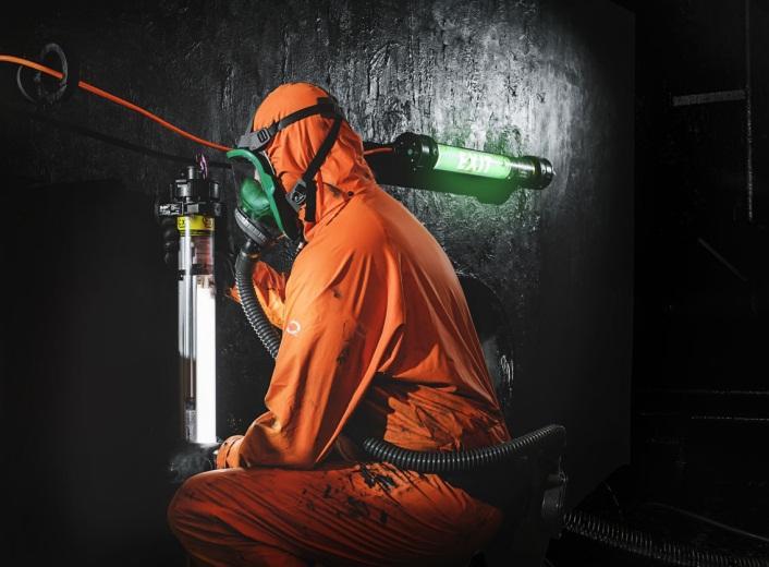
1 Instructions for Safe Use Certification N:o VTT 14 ATEX 041X and IECEx VTT X Thank you for choosing SLAM Hornet portable work light with battery back up for your job site. Purpose of this manual is to provide you all the necessary safety and product information to conduct your job conveniently and without any risks for health and safety. SLAM Hornet EM 1LED SLAM Hornet EXIT 1LED Atexor Oy Seinäjoki P.O.Box 89 FIN Seinäjoki FINLAND Tel: Trade Reg. No VAT No. FI
2 2/16 Contents Instructions for Safe Use Introduction to SLAM Hornet Technical data Certification of equipment Standard unit construction Quality guaranteed General Individual testing reports Prior to use Selection of right equipment Intended purpose of equipment Application of use (Zone XX) in accordance with equipment category Explosion group (IIA, IIB or IIC) in accordance with Equipment group (IIA, IIB or IIC) Temperature class of the equipment Environmental criteria Special conditions for safe use Operating instructions Personnel Storage of the SHEM Before first use of SHEM Visual inspection of SHEM Special attention on 2-pole use (24 V or 42 V) Connection to the supply Adding accessories to SLAM Hornet Linking in Series Special operating features of SHEM Inspection & Maintenance After Use Maintenance Testing Repair report Periodical testing of SHEM More information about the use of Electrical Apparatus for Explosive Gas Atmospheres Helpdesk... 16
3 3/16 1. Introduction to SLAM Hornet This instruction manual guides you through the process of selecting and adopting SLAM Hornet with battery back up work light at your work site. The manual regards the following SLAM Hornet types: 1.1 Technical data SLAM Hornet EM 1LED, SLAM Hornet EXIT 1LED (later SHEM) Dimensions / mm Product model L Ø SLAM Hornet EM 1LED A SLAM Hornet EXIT 1LED A SLAM Hornet EM 1LED C SLAM Hornet EXIT 1LED C Certification of equipment The SLAM Hornet series has been designed, tested and certified for portable use. There is X mark in the certificate for special conditions of safe use of the equipment. Special conditions of safe use specifies: Ambient temperature can be -20 C + 40 C without Ex-socket With Ex-socket as specified for the used socket but within -20 C + 40 C ib -marking is for internal protection of the switch in the emergency supply circuit. There is NO need for Exi assosiated apparatus in the supply of the luminaire The equipment is to be used properly and according to its ratings, documentation and local applicable laws. Local, national certificates of these units may exist outside the region of EU. The aforementioned SLAM Hornet types are certified as follows. You may find brief explanation of certificate beneath:
4 4/16 CE 0537 II 2 G Ex e ib mb op is IIC T4 Gb II 2 D Ex tb op is IIIC T90 C Db IP 66 CE 0537 = Valid production quality system approved and notified by VTT (Finnish Notified Body, listed by EC) = Certified for explosion hazardous areas II = Certified for use in areas excluding mines 2 = Equipment category (suitable for Zone 1 & 21 and Zone 2 & 22) G = Certification taking account explosion hazardous GASES D = Certification taking account explosion hazardous DUSTS Explanation of marking for explosion hazardous area due to Gases (Ex e ib mb op is IIC T4 Gb): Ex = Certified for use in explosion hazardous areas e = Explosion protection method increased safety (of certain components) ib = Explosion protection method intrinsic safety (of certain components) mb = Explosion protection method encapsulation (encapsulating ignition sources) op is = Explosion protection method optically inherently safe (visible or infrared radiation that is incapable of producing sufficient energy under normal or specified fault conditions to ignite a specific hazardous athmosphetic mixture). This definition is analogues to the term intrinsically safe applied to electrical circuits IIC = Equipment group (including explosion hazardous areas of IIA, IIB and IIC gases) T4 = Maximum inside temperature of the unit is 135 C (within the ambient temperature range of -20 C +40 C) Gb = Explosion Protection Level (EPL) marking for HIGH level of protection. Equipment for explosive GAS atmospheres, which is not a source of ignition in normal operation or during expected malfunctions Explanation of marking for explosion hazardous area due to Dusts (Ex tb op is IIIC T 90 C Db): Ex = Certified for use in explosion hazardous areas tb = Explosion protection method protection by enclosure IIIC = Equipment group for all dusts T90 C = Maximum OUTSIDE surface temperature of the unit is 90 C (within the ambient temperature range of -20 C +40 C) Db = Explosion Protection Level (EPL) marking for HIGH level of protection. Equipment for explosive DUST atmospheres, which is not a source of ignition in normal operation or during expected malfunctions
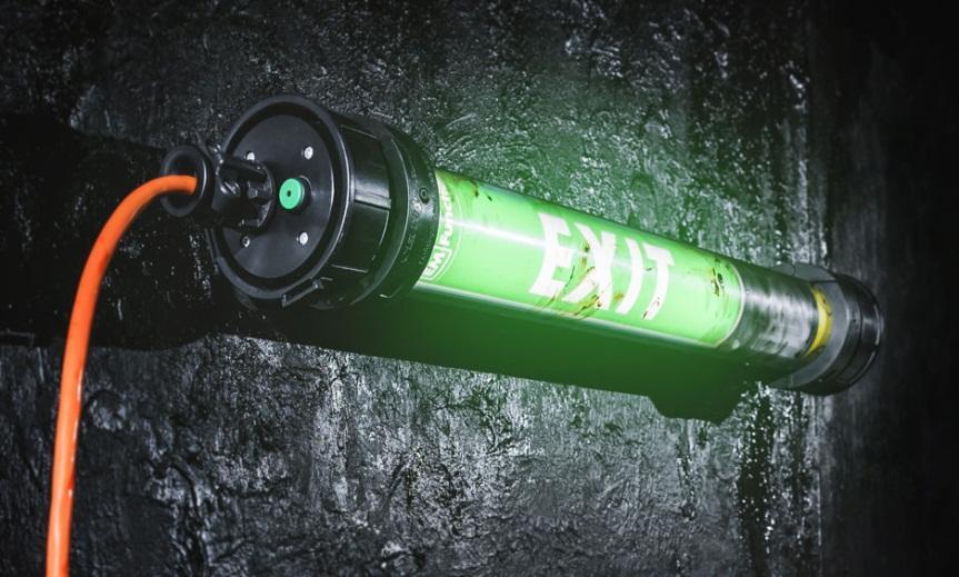
5 5/ Standard unit construction The following list familiarizes you with some common unit features important to recognize. End parts: Flexible, plastic-made end parts ensure shock-absorbing and harmless contact to sensitive and hard surface in case the luminary drops to the ground even from high position. Light construction affects the total weight of the unit itself. Transparent PC tube: Polycarbonate tube, being durable, flexible and lightweight plastic, brings advantage for use. Unique antistatic treatment allows the use of PC in explosion hazardous areas. Aluminium frame: Nearly all SLAM Hornet units are based on use of solid but flexible aluminium frame. Components are tightened with screws on it, making the unit tough and durable in severe conditions. Moreover, the frame derives excessive heat out from the luminary thereby extending lifetime of the unit. Electronic control gear: The control gear in controlling the supply of energy to the light source of the luminaire.the control gears are independent from each others. Under failure of one control gear, the other still continues operating. Low-voltage protection (smart-feature) brings reliability and convenience for use, especially when operating with transformers or with long cables. Led module (LED): Light source combining Light Emitting Diodes with convenient and safe light distribution. Led module is explosion protected. Photobiological safety of Led module has been taken into account. Cable: Standard cable of the SLAM Hornet series is H07BQ-F. This cable has polyurethane (PUR) outer sleeve. PUR withstands well chemicals as well mechanical wearing. However, the user has an option to specify cable type in accordance with work site requirements of own. Socket: Optional in-built sockets (receptacles) for linking the SLAM Hornet units in series Battery: The Ex-approved rechargeable Li-Ion battery provides power during the supply power failure. The external battery casing makes the battery more robust and suitable for harsh conditions. The battery temperature is monitored by the advanced control unit. Other common accessories (optional): Antistatic protective film for PC tube against chemical splashes and other substances SLAM Click n Fix 80 Magnetic Bracket SLAM Click n Fix 80 Scaffold Bracket SLAM Click n Fix 80 Unistrut Bracket SLAM Click n Fix 80 Single Bracket Adjustable hanging straps To view options on accessories, please visit for further study or call us directly
6 6/ Quality guaranteed General The SLAM Hornet series is designed, certified, manufactured and tested under ISO 9001:2008 quality system as well as additional requirements of the Directive 94/9/EC (ATEX) or IECEx scheme. The SLAM Hornet series is designed and tested according to the latest directives and standards. The referred directives and standards of the production date in case are stated on the Declaration of Conformity included in the delivery Individual testing reports Each SLAM Hornet unit has its own individual serial number and is provided with an original, individual testing report when leaving the factory. The year of manufacture is specified on the type label of the equipment. Following tests have been done for SLAM Hornet units according to standards relating to portable luminaries for explosion hazardous area. The Declaration of Conformity is specifying the relevant standards. The testing report which is included in the delivery specifies the results of the factory tests for that particular unit. The testing report typically specifies the following tests: PE resistance test The purpose of this test is to measure persistence of earth conductor. Vital test for electrical safety as well as explosion safety because of e.g static electricity control. The test current is 10 A (current) and the overall resistance should not exceed 0,5 W. High voltage test (electrical strength) The purpose of this test is to measure leakage current through insulation. Vital test for revealing broken components or similar failures which can not be identified visually. Testing voltage applied is 2130VDC. Maximum leakage current is 5mA. Test of expected use of equipment The luminary is subjected to shaking and vibration to see that all the internal wires are properly attached and components are not loose. Operational test of luminaire and accessories The unit is plugged-in and checked that it is working properly after all accomplished tests above. Visual inspection A final check to see everything is fine (screws attached properly, wires connected and required markings attached).
7 7/16 2. Prior to use 2.1 Selection of right equipment You need to be sure that the equipment you intend to take into explosion-hazardous area matches up with the zone classification and other safety requirements related. The operator is solely responsible for the correct selection and use of the equipment at his site. At least the following points should be notified prior to use: 2.2 Intended purpose of equipment Please keep in mind what the actual application of equipment is. For example in case the equipment is to be moved when connected to the supply it needs to be designed for that purpose. If the certification is mentioning portable it means that the equipment is suitable and tested for portable use. If the certification does not mention portable it means that the equipment shall not be moved when it is in operation (reliable fixing of equipment). SLAM Hornet units are designed and tested for portable use. 2.3 Application of use (Zone XX) in accordance with equipment category Operator has the best knowledge of area classification at his site. To help the operators selection of equipment the certification is describing the equipment category. For explosion hazardous areas there are three equipment categories. Category 1 product is suitable for use in Zones 0, 1 and 2 / (20, 21 and 22) Category 2 product is suitable for use in Zones 1 and 2 / 21 and 22 Category 3 product is suitable for use in Zones 2 / (22) SLAM Hornet units mentioned in this instruction fall into Category 2 equipment. 2.4 Explosion group (IIA, IIB or IIC) in accordance with Equipment group (IIA, IIB or IIC) This information is vital because the substances require different amount of energy to be ignited. Safety requirements for equipment are not the same for different substances (e.g. static electricity requirements).therefore making the selection easier the gases are divided to three different groups (IIA, IIB and IIC). Further information about the substances can be found from EN/IEC (Data for flammable gases and vapours, relating to the use of electrical apparatus). SLAM Hornet units mentioned in this instruction are Equipment group IIC.
8 8/ Temperature class of the equipment Please observe the Ignition Temperature (IT) of the substance creating the explosion hazard at your site. Select the equipment based on IT of the substance. The temperature of the equipment must be lower than IT. The highest temperature of the equipment is specified by using Temperature Classes T1 to T6. Example: Petroleum ignition temperature is approximately 250 C à Maximum allowed temperature class of the equipment is T3 (< 200 C) SLAM Hornet units mentioned in this instruction are Temperature Class T4 (GASES) SLAM Hornet units mentioned in this instruction maximum surface temperature of 90⁰C (DUSTS) 2.6 Environmental criteria Please observe the ambient temperature of the application in use because certification is valid for temperatures between -20 C +40 C. Some SLAM Hornet luminaries are certified for temperatures between -40 C +40 C. Please see type label of the product for further data. If the equipment is used in other temperatures than mentioned the safety can not be guaranteed. Selection and use of equipment is always under the responsibility of the operator. Please note that all of the aforementioned criteria are to be fulfilled when selecting the equipment. Please do not take any unnecessary risks. 2.7 Special conditions for safe use As the marking ib is for internal protection of NTC, push button and signal LED circuits in the EM control unit, there is no need for Exi-associated apparatus in the supply of the luminaire.
9 9/16 3. Operating instructions 3.1 Personnel The use of the equipment is to be controlled and accepted by the operator. The personnel using the unit have to be authorized by the operator or his representative. In case of further training of using the equipment please contact the local supplier of this equipment. 3.2 Storage of the SHEM SHEM units should be stored in normal operating temperatures -20 C +40 C. To achieve the best lifetime for the battery it is recommended that the unit is stored in ambient temperature +5 C +10 C and the battery is charged approximately every three months if not used. 3.3 Before first use of SHEM Before first use, connect the unit to mains/transformer for 24 hours to fully charge backup battery. This is necessary to get maximum battery life and capacity. Battery lasts ~600 cycles or 3-4 years in normal operation. See also section Visual inspection of SHEM As for all equipment to be used inside explosion hazardous area it is recommended that before taking the unit into Ex area, a visual re-inspection on the unit was taken and an analysis made that the unit is not damaged (e.g. any part or wires are loose damaged or disconnected) In case faults or defects on the unit are noticed, it is prohibited to take such a unit into Ex area until the corrective actions have been made. 3.5 Special attention on 2-pole use (24 V or 42 V) Certain SHEM units are designed to be used together with step-down transformers. Using SHEM unit with transformers of 2-pole socket outlets (without grounding / bonding) imposes certain extra requirements for the unit itself. All the external metal and aluminium parts of the SHEM are replaced by the manufacturer with plastic parts or equipped with plastic covers in order to avoid electrostatic charging and a consequent risk of explosion. This process can only be done by manufacturer because the certification of the product. Please inform us about your requirement for 2-pole use when placing the order. Products originally manufactured for 3-pole use can not be modified later for 2-pole use by the operator. Such modifications are only allowed to be carried out by the manufacturer or under supervision of the manufacturer.
10 10/16 Note! Lack of equipotential bonding may cause danger in Ex area, therefore please pay special attention to all installations of yours involving metallic parts. Static charging is especially noted on standards referring to installations in explosion hazardous areas (e.g. EN/IEC ). 3.6 Connection to the supply It is recommended that the unit is first connected to the mains / transformer before entering the explosion hazardous area. Potential equalization should be arranged by the operator prior entering explosion hazardous area. SLAM Hornet units with 2-pole supply (without bonding connection) can be taken to explosion hazardous area without connecting it to the supply first. Requirements for supply (electricity) The following main requirements should be taken into account: Supply voltage: Variation may be maximum ±6% from the value stated in the unit type label. Current: Maximum current of the system is 16 A. Frequency: Standard 50 Hz if not otherwise stated in the type label. Fuse protection: The supply has a fuse with a breaking capacity of at least 1500 A. Earth Leakage Circuit Breaker (ELCB): It is recommended to use a supply with 30 ma ELCB. Please observe the type label for further data. Luminaires for 110 VAC or 230 V supply are to be connected to a supply incorporating protective earth conductor. 3.7 Adding accessories to SLAM Hornet Atexor provides a number of different accessories but in case you afterwards want to add accessories of your own for the SHEM unit, please note the following points: 1. The user is fully responsible for the use of the equipment including service and maintenance 2. In case of adding accessories the following is mandatory a. The construction of the certified unit shall not change b. The IP class of the unit shall not decrease 3. The static electricity is taken account (e.g. electrostatic bonding) In case you do not want to do your own risk assessment for the accessories please view the whole range of accessories at Linking in Series Certain SLAM Hornet units may be equipped with Ex-certified socket in the factory. Sockets are considered as one option so they are added to the unit upon customer s special request.
11 11/16 In-built sockets are recommended when the illuminated area is notably large, complex or not enough wiring points are available. Linking the units in series save time, amount of cable and provide an opportunity to build a chain of lights to provide enough illumination in the darkness. When linking SLAM Hornet units together, please take the following steps: 1) Connect the first luminaire to the power supply and power it up. 2) Then connect the other luminaries to each other one by one and power them up individually 3) The in-built socket is only for chaining SLAM Hornet units. Luminaires should be powered up in series and powering up the whole chain as one need to be avoided. Amount of lights which may be connected with each other depends on the supply voltage. Competent person of the operator shall control and accept the temporary electrical installation at the site. Before connecting SLAM Hornet luminaries together, please ensure the following points: 1. The total length of the light chain does not exceed 66 meters. Please see additional detail below the chart. 2. The total current of the electrical installation does not exceed 16A. Here you may see general and theoretical guide-lines for linking SLAM Hornet luminaires with 5 m 3x1.5mm 2 (or 3x2.5mm 2 ) cable: Supply voltage 230 V 110 V 42 V 24 V Type of luminaire SHEM1LED (30 W) SHEM1LED (30 W) SHEM1LED (30 W) SHEM1LED (30 W) Number of luminaires in series Please note that even if the voltage drop allows certain amount of luminaries to be linked together, too long chain of luminaries may affect the ability of the fuses in the electrical input to work properly in a fault situation. Therefore it is not recommended to chain luminaries to a longer chain than 66m measured from the protective fuse (when the electrical supply is protected with C-curve fuse). Please refer to local applicable laws and requirements for electrical installations. The SHEM control gear protects itself against excessive voltage drops (numerous linking) by switching itself off. If too many units are connected to the chain, some units of the chain will switch off. You may start up by unplugging the last units on the line.

12 12/16 Voltage peaks are more harmful and may damage the ballast permanently when subjected to excessive peaks continuously. If fluorescent tubes are flickering when the units are chained up, it may be due to excessive linking. This may shorten notably the lifetime of fluorescent tube. Unplug the last unit on the line to ensure proper function of the unit. 3.9 Special operating features of SHEM Connect luminaire to the mains/transformer. Push the power button on the end part to turn the luminaire on and off. Power button has an integrated standby/power LED to ease finding the button at dark enviroments and indicating that the luminaire is powered. All SHEM -units are equipped with Li-Ion battery backup to allow the LED module to illuminate at up to 35% of the normal light output during power failures. When the backup is functioning the LED module blinks shortly every 15 seconds as an indication of the missing power supply. Battery backup function operates up to 90 minutes depending on the condition and charge of the battery (also see 4.5). By using the power button also the operation of battery backup can be controlled on and off. Battery is charging whenever the luminaire is connected to the mains/transformer and the battery temperature is below +60 C. The temperature of the battery is monitored by the charging circuitry to prevent overtemperature charging. The battery charging in subzero temperatures is not prevented, but it is highly recommended that the charging is done only in ambient temperatures between +0 C +40 C. Function diagram Indicator Status Chart Button LED (power) OFF BLINKING State No power Powered / Battery charging
 Clean the unit with a damp cloth (do not use detergents or solvents) 2) Change the anti-static film if")
13 13/16 LIT Powered / Battery full 4. Inspection & Maintenance 4.1 After Use Take the following steps after the SHEM -unit has been taken out from Ex-area: 1) Clean the unit with a damp cloth (do not use detergents or solvents) 2) Change the anti-static film if only little light comes through it or it is damaged 3) Have a visual check on the unit (condition of cable, PC-tube, tightness of parts) 4) Let the unit dry in open air 4.2 Maintenance The following procedure should be taken in case the SHEM -unit needs to be repaired: 1) Maintenance may be carried out only outside Ex area 2) Person responsible for maintenance should have been trained the basics of explosionprotection as well electricity 3) Only original spare parts from the manufacturer should be used. Please note that there are no components in this unit which can be repaired by using glue, silicone or any other similar method. 4) The dissipation feature (antistatic) on transparent parts of SLAM Hornet may be damaged because of external affects like solvents or chemicals or mechanical stress. In case the surface of the PC-tube is damaged in one area greater than 100 cm 2 the part has to be changed. The surface resistance of the transparent parts has to be between 1 MΩ 1 GΩ. Please contact Atexor Oy in case You need a simple measuring device, which is needed for measuring surface resistance of the PC-tube. 5) Maintenance instructions with exploded-view diagram and spare parts list are available at your local distributor and the manufacturer. Please, when requesting maintenance instructions with exploded-view diagrams, include the model and serial number of the product. The device has a Li-Ion battery and electronics inside, please use required actions when disposing of the device or its components. 4.3 Testing Tests are to be done according to EN/IEC until returning the repaired unit back to operation. Below mentioned tests shall be done in addition to the tests specified in EN/IEC PE resistance test
14 14/16 High-voltage test (500 VDC between Phase & Neutral against P/E conductor) Operational test Test of expected use (vibrations, shaking) Proper testing ensures safe operation of repaired equipment. 4.4 Repair report The operator is responsible for keeping up to date record of the condition of his equipment (EN/IEC ). Ensuring the availability of this important information each repair procedure should be written down in repair report according to EN/IEC This report should reveal at least: Person who conducted the maintenance Date of maintenance Procedure of maintenance Signature of person responsible accepting the maintenance 4.5 Periodical testing of SHEM Before test, allow battery to be fully charged. Operation of the battery must be checked 4 times a year by cutting off the input voltage. Operation time in battery mode should be over 45 minutes. If not, luminary is to be serviced. 4.6 More information about the use of Electrical Apparatus for Explosive Gas Atmospheres Please observe the requirements of the valid standards of the day. Please study at least the following standards: EN/IEC (Electrical installations in hazardous areas) EN/IEC (Classification of hazardous areas) EN/IEC (Inspection and maintenance of electrical installations in hazardous areas) EN/IEC (Repair and overhaul for apparatus used in potentially explosive atmospheres)
15 15/16

16 16/16 Helpdesk Under any doubt or question, please contact your local distributor or the manufacturer. Contact details: Phone: Fax: Web:
(Certification N:o VTT 08 ATEX 066 or IECEx VTT )
") (Certification N:o VTT 08 ATEX 066 or IECEx VTT 12.0009) Thank you for choosing Slam Hornet portable work light for your job site. Purpose of this manual is to provide you all the necessary safety and
(Certification N:o VTT 08 ATEX 066 or IECEx VTT 12.0009) Thank you for choosing Slam Hornet portable work light for your job site. Purpose of this manual is to provide you all the necessary safety and
Operating Instructions
 LPL Series LED Pendant Lighting Operating Instructions IM0102 COOPER Electronic Technologies (Shanghai) Co., Ltd. No. 955 Shengli Road, East Area of Zhangjiang High-Tech Park, Shanghai 201201 China 1.
Further technical information is available on
 1 of 5 Manufacture address : Bartec Technor AS Dusavikveien 39 4007 Stavanger Norway Further technical information is available on www.bartec-technor.no Note on instructions When working in hazardous areas,
1.8 INDUSTRIAL PROCESS WEIGHING IN HAZARDOUS AREAS
 1.8 INDUSTRIAL PROCESS WEIGHING IN HAZARDOUS AREAS EXPLOSION PROTECTION In addition to the type approval and certification of industrial weighing systems concerned with accuracy, equipment that is also
Arran LED Floodlight Luminaire
 Arran LED Floodlight Luminaire INSTALLATION, OPERATION AND MAINTENANCE INSTRUCTIONS Important: Please read these instructions carefully before installing or maintaining this equipment. Good electrical
VG5 Supplementary instructions
 VG5 Supplementary instructions 2-wire / 10 GHz Radar (FMCW) Level Meter Supplementary Instructions for ATEX applications HYCONTROL CONTENTS VG5 1 General safety information 4 1.1 Scope of the document...
OSAT Series. Intrinsically Safe Infrared Temperature Sensor Operator's Guide
 OSAT Series Intrinsically Safe Infrared Temperature Sensor Operator's Guide Issue L Jan 2017 Introduction OSAT Series intrinsically safe non-contact infrared temperature sensors measure the temperature
Technical Data. Dimensions
 00 Model Number Features Comfort series 30 mm non-flush Accessories MHW 0 Modular mounting bracket V-G Female connector, M, 4-pin, field attachable V-W-N-M-PUR Female cordset, M, -pin, NAMUR, PUR cable
NZQA registered unit standard version 3 Page 1 of 7. Plan electrical installations for explosive atmospheres
 Page 1 of 7 Title Plan electrical installations for explosive atmospheres Level 5 Credits 8 Purpose This unit standard is intended for use in the training and assessment of people who work with electrical
VS18/26 with PROFINET and EtherNet/IP Interface. ATEX Installation Instructions
 VS18/26 with PROFINET and EtherNet/IP Interface ATEX Installation Instructions INDEX 1. INTENDED USAGE 3 2. OPERATING MANUAL ATEX 4 2.1 General conditions 4 2.2 Installation 5 2.3 Operating 5 2.4 Failures
OPERATION MANUAL PNEUMATIC VALVES
 OPERATION MANUAL PNEUMATIC VALVES DIRECTIVE 2014/34/EU ATEX ENGLISH Index 1 Product identification 2 Security 3 Guarantee 4 Transportation 5 Assemblage 6 Setting up 7 Adjustments 8 Technical information
Technical Data. Dimensions
 0102 Model Number Features Comfort series 15 mm flush Accessories MHW 01 Modular mounting bracket MH 04-2057B Mounting aid for VariKont and +U1+ V1-G-N-2M-PUR Female cordset, M12, 2-pin, NAMUR, PUR cable
DK46 - DK800 Supplementary instructions
 DK46 - DK800 Supplementary instructions Variable area flowmeter Device category II2G with electrical internals Additional Ex manual KROHNE CONTENTS DK46 - DK800 1 Safety instructions 3 1.1 General... 3
Magnetic level switch type MR783 Instruction Manual
 Magnetic level switch Magnetic level switch type MR783 1. DESCRIPTION page 3 1.1 Operation page 3 1.2 Application page 3 1.3 Description page 3 2. SPECIFICATIONS page 3 2.1 Service Conditions page 4 2.2
NZQA registered unit standard version 1 Page 1 of 8. Conduct detailed inspection of electrical installations for explosive atmospheres
 Page 1 of 8 Title Conduct detailed inspection of electrical installations for explosive atmospheres Level 5 Credits 5 Purpose This unit standard is intended for use in the training and assessment of people
Pressure switch KP-E. Data sheet
 Data sheet Pressure switch KP-E KP-E pressure switches for use in refrigeration and air conditioning systems are equipped with SPDT gold plated contacts and stainless steel bellows. The high pressure switches
Operating Instructions
 Operating Instructions Light-metal Ex d enclosures / flameproof enclosure > 8265/0 Empty enclosure > 8265/4 Control panel, integrated in Ex e enclosure > 8265/5 Control panel Table of Contents 1 Table
SC505 Sof Care Inflator. Operating Instructions and Service Manual
 SC505 Sof Care Inflator Gaymar Industries, Inc. 10 Centre Drive Orchard Park, NY 14127 Toll Free +1 800.828.7341 + 1 716.662.2551 Fax +1 800.993.7890 Outside USA +1 716.662.8636 Outside USA Fax +1 716.662.0730
ATEX, IECEx and MET (Class I, Division 1) Safety Instructions icam502
 Safety Instructions icam502") ATEX, IECEx and MET (Class I, Division 1) Safety Instructions icam502 This device complies with part 15 of the FCC Rules. Operation is subject to the following two conditions: (1) This device may not cause
ATEX, IECEx and MET (Class I, Division 1) Safety Instructions icam502 This device complies with part 15 of the FCC Rules. Operation is subject to the following two conditions: (1) This device may not cause
Technical Data. Dimensions
 00 Model Number Features mm flush Usable up to SIL acc. to IEC 6508 Accessories V-G Female connector, M, -pin, field attachable V-W Female connector, M, -pin, field attachable V-G-N-M-PUR Female cordset,
MODELS (2 foot Version) (4 foot Version)
 (4 foot Version)") INSTALLATION AND MAINTENANCE MANUAL DUROSITE LED LINEAR FIXTURE Document No: 9100-127-2571-99 Rev A April, 2016 MODELS (2 foot Version) (4 foot Version) ALL LAE ALL LBE These instructions contain important
INSTALLATION AND MAINTENANCE MANUAL DUROSITE LED LINEAR FIXTURE Document No: 9100-127-2571-99 Rev A April, 2016 MODELS (2 foot Version) (4 foot Version) ALL LAE ALL LBE These instructions contain important
Operating instructions Safety Rope Emergency Stop Switches ZB0052 / ZB0053 ZB0072 / ZB0073
 Operating instructions Safety Rope Emergency Stop Switches UK ZB0052 / ZB0053 ZB0072 / ZB0073 7390878 / 02 03 / 2011 Contents 1 Safety instructions...3 2 Installation / set-up...4 2.1 Applications...4
Technical Data. Dimensions
 0102 Model Number Features 10 mm flush Shielded PUR cable for oil and gas sector Accessories BF 30 Mounting flange, 30 mm Technical Data specifications Switching function Normally closed (NC) Output type
Columbus Instruments
 0215-003M Portable O 2 /CO 2 /CH 4 Meter User s Manual Columbus Instruments 950 NORTH HAGUE AVENUE TEL:(614) 276-0861 COLUMBUS, OHIO 43204, USA FAX:(614) 276-0529 1 www.colinst.com TOLL FREE 1-800-669-5011
LTB013EN. Operating Instruction Trimod Besta Level Switch types XA 5, XB 5 for use in potentially explosive atmospheres acc.
 LTB013EN Operating Instruction Trimod Besta Level Switch types XA 5, XB 5 for use in potentially explosive atmospheres acc. to IECEx scheme Subject to technical modification Bachofen AG Ackerstrasse 42
Dimensions. Technical Data General specifications Switching element function Rated operating distance s n 5 mm
 Dimensions M18x1 37 40 4 0102 24 LED Model Number Features 5 mm embeddable Usable up to SIL2 acc. to IEC 61508 Connection BN BU Accessories L+ L- EXG-18 Quick mounting bracket with dead stop BF 18 Mounting
ABTQ-110 rev 00 (Last review: 28 Aug 12) INSTALLATION, OPERATION & MAINTENANCE INSTRUCTIONS FOR ABTECH S RANGE ENCLOSURES IECEx SIR U SERIAL No
 INSTALLATION, OPERATION & MAINTENANCE INSTRUCTIONS FOR ABTECH S RANGE ENCLOSURES IECEx SIR U SERIAL No") ABTQ-110 rev 00 (Last review: 28 Aug 12) INSTALLATION, OPERATION & MAINTENANCE INSTRUCTIONS FOR ABTECH S RANGE ENCLOSURES IECEx SIR 05.0046U SERIAL No 20 TYPE SX Ex e II C Gb Ex tb IIIC Db IP6* IECEx SIR
ABTQ-110 rev 00 (Last review: 28 Aug 12) INSTALLATION, OPERATION & MAINTENANCE INSTRUCTIONS FOR ABTECH S RANGE ENCLOSURES IECEx SIR 05.0046U SERIAL No 20 TYPE SX Ex e II C Gb Ex tb IIIC Db IP6* IECEx SIR
Floodlight LED. Series Operating instructions EN EN EN EN EN EN EN EN EN EN EN EN EN EN EN EN EN EN EN EN EN EN EN EN
 Floodlight LED Operating instructions Additional languages www.stahl-ex.com General Information Contents 1 General Information...2 1.1 Manufacturer...2 1.2 Information regarding the operating instructions...3
RTD temperature probes
 RTD temperature probes Ex i for use in areas with an explosion hazard (Ex areas) Persons concerned: Experienced professional electricians as per EU Directive 1999/92/EC and trained personnel Operating
Technical Data. General specifications Switching element function Rated operating distance s n 5 mm
 00 Model Number Features 5 mm flush Usable up to SIL acc. to IEC 6508 Accessories V-G Female connector, M, -pin, field attachable V-W Female connector, M, -pin, field attachable V-G-N-M-PUR Female cordset,
USER MANUAL. JET TST and JET TST S.
 USER MANUAL JET TST and JET TST S www.sisteven.com Types of Jet fans: JET TST UNI: Impulse axial fan single direction JET TST S UNI: Impulse axial fan single direction (short case) JET TST REV: Impulse
Safety. Operating instructions Solenoid valve for gas VG 6 VG 15/10 DANGER. Contents WARNING CAUTION. Changes to edition 09.14
 15 Elster GmbH Edition 7.15 Translation from the German 519 D F NL I E DK S N P GR TR CZ PL RUS H www.docuthek.com Operating instructions Solenoid valve for gas VG VG 15/1 Contents Solenoid valve for gas
Reg No: 1999/027771/07 ACCREDITED AND APPROVED TEST LABORATORY IN TERMS OF ARP 0108: REGULATORY REQUIREMENTS FOR EXPLOSION PROTECTED APPARATUS
 Government Approved Test Laboratory (Previously AIA) Reg No: 1999/027771/07 ACCREDITED AND APPROVED TEST LABORATORY IN TERMS OF ARP 0108: REGULATORY REQUIREMENTS FOR EXPLOSION PROTECTED APPARATUS ZEST
Technical Data. General specifications. Rated operating distance s n 5 mm
 0102 Model Number Features 5 mm flush Usable up to SIL 2 acc. to IEC 61508 Accessories EXG-18 Quick mounting bracket with dead stop BF 18 Mounting flange, 18 mm Technical Data specifications Switching
Floodlight LED. Series Operating instructions EN EN EN EN EN EN EN EN EN EN EN EN EN EN EN EN EN EN EN EN EN EN EN EN
 Floodlight LED Operating instructions Additional languages www.r-stahl.com Contents 1 General Information...3 1.1 Manufacturer...3 1.2 Information regarding the operating instructions...3 1.3 Conformity
Pressure control, differental pressure control and thermostat Type RT
 MAKING MODERN LIVING POSSIBLE Technical brochure Pressure control, differental pressure control and thermostat Type RT Hydrocarbons www.danfoss.com/hydrocarbons Contents Page Introduction...3 Approvals...3
Temperature gauge Installation Guide
 Temperature gauge Installation Guide improper functioning, or damage. Additional information can be found at: CAUTION: Read this installation guide carefully before unpacking the temperature gauge. Improper
EX-RECESSED CEILING LIGHT FITTINGS
 EX-RECESSED CEILING LIGHT FITTINGS RLF/RLF-INOX 250 18-58 W / RLF/RLF-INOX 250... N 18-36 W Metallic design for Zone 1 and Zone 21 The RLF... explosion-protected recessed ceiling light fittings with electronic
Rigel 601 CHECKBOX. Instruction Manual. 348A551 Issue 2.0. April Seaward Electronic Ltd. Issue 2.0
 Rigel 601 CHECKBOX Instruction Manual 348A551 Issue 2.0 April 2006 2006 Seaward Electronic Ltd. Issue 2.0 Limited Warranty & Limitation of Liability Rigel Medical guarantees this product for a period of
Pressure switch, Differential pressure switch and Thermostat RT-E
 Data sheet Pressure switch, Differential pressure switch and Thermostat RT-E The RT-E series consist of pressure and differential pressure switches as well as thermostats. The units are designed for industrial
Pressure Measurement Single-range transmitters for general applications
 Siemens A 207 Overview Application The SITRANS P Compact pressure transmitter is designed for the special requirements of the food, pharmaceutical and biotechnology industries. The use of high-grade materials
User s Manual EJX/EJA-E Series NEPSI Certification [Option code: /NF2, /NS21, /NS24 and /NS25] IM 01C25A00-12E
![User s Manual EJX/EJA-E Series NEPSI Certification [Option code: /NF2, /NS21, /NS24 and /NS25] IM 01C25A00-12E](/thumbs/86/93658860.jpg "User s Manual EJX/EJA-E Series NEPSI Certification [Option code: /NF2, /NS21, /NS24 and /NS25] IM 01C25A00-12E") User s Manual EJX/EJA-E Series NEPSI Certification [Option code: /NF2, /NS21, /NS24 and /NS25] 12th Edition 1 1. Introduction Thank you for purchasing the DPharp electronic pressure transmitter. This manual
User s Manual EJX/EJA-E Series NEPSI Certification [Option code: /NF2, /NS21, /NS24 and /NS25] 12th Edition 1 1. Introduction Thank you for purchasing the DPharp electronic pressure transmitter. This manual
Actuating elements for ComEx
 Description A large number of variants and versions of actuating elements are available for the ComEx control and indicator units. All actuating elements are made of high-quality thermoplastic and conform
E2K-L. Liquid Level Sensor That Is Unaffected by the Color of the Pipe or Liquid. Liquid Level Sensor. Ordering Information
 Liquid Level EK-L CSM_EK-L_DS_E 3 Liquid Level That Is Unaffected by the Color of the or Liquid Mount to bypass pipes. Fit a wide range of pipe diameters: 8 to mm or to mm Built-in Amplifiers to save space.
4/2 way Pneumatic Solenoid Valve
 4/2 way Pneumatic Solenoid Valve Compact design Push-over solenoid coil Exhaust air can be regulated Tube, threaded and sub-base connections Type combined with Seat valve version Type 2508 Type 2510/11
Technical Data. Dimensions
 0102 Model Number Features Comfort series 5 mm flush Usable up to SIL 2 acc. to IEC 61508 Accessories BF 18 Mounting flange, 18 mm EXG-18 Quick mounting bracket with dead stop Technical Data specifications
Technical Data. Dimensions
 0102 Model Number Features Comfort series 15 mm non-flush Stainless steel housing Accessories BF 30 Mounting flange, 30 mm Technical Data specifications Switching element function NAMUR, NC Rated operating
Dimensions. Technical Data General specifications Switching element function Rated operating distance s n 10 mm
 Dimensions M30x1,5 5 40 37 0102 Model Number 36 LED Features Comfort series 10 mm embeddable Connection BN BU Accessories BF 30 Mounting flange, 30 mm L+ L- Technical Data specifications Switching element
Air Sensor. SAC Ex. Manual ATEX. AQ Elteknik AB
 Air Sensor SAC Ex Manual AQ Elteknik AB ATEX Air Sensor SAC Ex ATEX Certified model Manual version 2.1 April 2014 AQ Elteknik AB 2 Table of contents 1. Manufacturer information... 4 Manufacture Declaration
Compact differential pressure switch Flameproof enclosure Ex d Models DE, DEC
 Mechatronic pressure measurement Compact differential pressure switch Flameproof enclosure Ex d Models DE, DEC WIKA data sheet PV 35.41 Process Compact Series Applications Differential pressure monitoring
Digital Melting Point Apparatus
 Digital Melting Point Apparatus Heating Plateau Ramping Start/Stop Plateau set Ramp stop Hold User Guide Version 1.1 Heating Viewing tube Sample Chamber IEC power inlet socket Power on/off Temperature
EC214 EC215 - EC215R Bench Conductivity Meters
 Instruction Manual EC214 EC215 - EC215R Bench Conductivity Meters http://www.hannainst.com These Instruments are in Compliance with the CE Directives Dear Customer, Thank you for choosing a Hanna Instruments
IECEx certification of Non-Electrical Ex Equipment
 IECEx certification of Non-Electrical Ex Equipment Thierry Houeix Ex Certification Officer Brief history of Non Electrical Ex Equipment standards In 2008, during the SC31M Plenary meeting it was decided
Technical Data. General specifications Switching element function Rated operating distance s n 2 mm
 0102 Model Number Features 2 mm flush Usable up to SIL 2 acc. to IEC 61508 Accessories EXG-12 Quick mounting bracket with dead stop BF 12 Mounting flange, 12 mm Technical Data specifications Switching
Technical Data. General specifications. Rated operating distance s n 2 mm
 0102 Model Number Features 2 mm flush Usable up to SIL 2 acc. to IEC 61508 Technical Data specifications Switching function Normally closed (NC) Output type NAMUR Rated operating distance s n 2 mm Installation
ELECTRICAL (COMPREHENSIVE) SAFETY PROGRAM REGULATORY STANDARD: OSHA - 29 CFR CFR , ,
 SAFETY PROGRAM REGULATORY STANDARD: OSHA - 29 CFR CFR , ,") ELECTRICAL (COMPREHENSIVE) SAFETY PROGRAM REGULATORY STANDARD: OSHA - 29 CFR 1910.331 335-29 CFR 1926.302, 1926.416, 1926.417 BASIS: The National Safety Council estimates that there are at least 300 deaths
ELECTRICAL (COMPREHENSIVE) SAFETY PROGRAM REGULATORY STANDARD: OSHA - 29 CFR 1910.331 335-29 CFR 1926.302, 1926.416, 1926.417 BASIS: The National Safety Council estimates that there are at least 300 deaths
Instruction Manual for Intrinsically Safe - Reed Switches
 Instruction Manual for Intrinsically Safe - Reed Switches Option Code: -1S2-IS-LED or -2S2-IS-LED -1S2-IS or -2S2-IS ATEX RCM Industries, Inc. Direct Reading Differential Pressure Flowmeters 110 Mason
* * Data Sheet and Operating Manual. Digital manometer ME01 ## # 87 # HL S#### Dust explosion protection Zone 22.
 *09005087* DB_BA_EN_ME01_S Rev.A 12/16 *09005087* d e v e l o p i n g s o l u t i o n s Data Sheet and Operating Manual ME01 Digital manometer Table of Contents ME01 ## # 87 # HL S#### Dust explosion protection
The definition of a competent person given in the Electricity at Work Regulations 1989 (EWR) is as follows:
 is as follows:") Electrical Safety Guidance Note 1 - General Guidance Competent Person The definition of a competent person given in the Electricity at Work Regulations 1989 (EWR) is as follows: "A person in the possession
Electrical Safety Guidance Note 1 - General Guidance Competent Person The definition of a competent person given in the Electricity at Work Regulations 1989 (EWR) is as follows: "A person in the possession
Technical Data. Dimensions
 0102 Model Number Features 6 mm flush Usable up to SIL 3 acc. to IEC 61508 Application Danger! In safety-related applications the sensor must be operated with a qualified fail safe interface from Pepperl+Fuchs,
Ground Fault Circuit Interrupter(GFCI) Policy
 Policy") NewStar Netronics, LLC American Products for the World Ground Fault Circuit Interrupter(GFCI) Policy 3926 East 3 rd Street Tulsa, OK 74112 Phone (918)894-5006 Fax (918)836-9909 tech@newstarnetronics.com
NewStar Netronics, LLC American Products for the World Ground Fault Circuit Interrupter(GFCI) Policy 3926 East 3 rd Street Tulsa, OK 74112 Phone (918)894-5006 Fax (918)836-9909 tech@newstarnetronics.com
PPS PORTABLE POWER SUPPLY
 PPS User Manual Rev 1-2015 ENG MASTER PPS PORTABLE POWER SUPPLY Disclaimer About ActSafe Safety messages and warnings Product safety System description Pre-use inspection and connection General safety
Safe Schools: A Health and Safety Check
 Name of School: Optional Information Date of Inspection: Vocational Program/Course/Room: Signature of Inspector: Use of Electrical Equipment Self-Inspection Checklist Guidelines: This checklist covers
ATEX heated hoses of series WEX7
 Instruction for Installation and Operation ATEX heated hoses Series WEX7 (fixed resistance heating cable) WEX7P WEX7G WEX7W Issue 10 / 2017 1 of 12 Important safety information for the use of ATEX heated
Technical Data. General specifications Switching element function Rated operating distance s n 1.5 mm
 0102 Model Number Features 1.5 mm flush Accessories BF 8 Mounting flange, 8 mm Technical Data specifications Switching element function NAMUR, NC Rated operating distance s n 1.5 mm Installation flush
Safety Instructions Liquiphant FailSafe FTL80, FTL81, FTL85
 XA01537F-A/00/EN/01.16 71333275 Products Solutions Services Safety Instructions Liquiphant FailSafe FTL80, FTL81, FTL85 0Ex ia IIC T6 Ga X Ga/Gb Ex ia IIC T6 X Document: XA01537F-A Safety instructions
E8AA. Pressure Sensor of Stainless Steel Construction Is Ideal for a Wide Range of Applications. Pressure Sensor (Stainless Steel Diaphragm)
") Pressure Sensor (Stainless Steel Diaphragm) CSM DS_E_3_1 Pressure Sensor of Stainless Steel Construction Is Ideal for a Wide Range of Applications Incorporates double diaphragms consisting of SUS316L stainless
Pressure Sensor (Stainless Steel Diaphragm) CSM DS_E_3_1 Pressure Sensor of Stainless Steel Construction Is Ideal for a Wide Range of Applications Incorporates double diaphragms consisting of SUS316L stainless
CJMJ.DPNQBDU. Instruction for use. Neonatal phototherapy device. BILI-COMPACT WY 1816/ Year of manufacture D2017_00
 Instruction for use Neonatal phototherapy device CJMJ.DPNQBDU D2017_00 GmbH > BILI-COMPACT WY 1816/ Year of manufacture Herrenhöhe 4 D-51515 Kürten/Germany 02207-9698-0 02207-4750 E-mail: info@weyermed.com
Hazardous Location Coding System - NEC 500. Type of Protection. XP = Explosionproof. IS = Intrinsically Safe Apparatus
 Hazardous Location Equipment - United States Equipment listed in this category for Hazardous (Classified) Locations is also suitable for installations in areas that are unclassified locations and, unless
II 2G EEx ia IIC T6. Ignition protection class
 ATEX General information According to 94/9/EC, a device that is to be used in an environment at risk of explosion may only be brought into the market if it satisfies the standards specified in the norm.
C&G 2395 Exam Paper June Section A-All questions carry equal marks. Answer all three questions. Show all calculations.
 C&G 2395 Exam Paper June 2013 Section A-All questions carry equal marks. Answer all three questions. Show all calculations. 1. The electrical installation in an industrial unit is scheduled for a periodic
Pressure Switches Application Guideline
 Pressure Switches Application Guideline Product Overview The Fema Pressure Switch product portfolio provides devices suitable for many applications. The portfolio contains Special functions and equipment
TABLE OF CONTENTS 2 TALAS DRYER 4 TALAS MEASURER 7 TALAS PORTABLE DRYER 9 TALAS LEAKER 11 TALAS STARTER 14 TALAS AUXILIARY 17 APPENDICES
 TABLE OF CONTENTS 2 TALAS DRYER 4 TALAS MEASURER 7 TALAS PORTABLE DRYER 9 TALAS LEAKER 11 TALAS STARTER 14 TALAS AUXILIARY 17 APPENDICES ALL PICTURES SHOWN ARE FOR REFERENCE ONLY ACTUAL PRODUCT MAY VARY
VA FLOWMETERS Supplementary Instructions
 VA FLOWMETERS Supplementary Instructions Variable area flowmeters without electrical built-ins Equipment category II 2 G, II 2 D KROHNE CONTENTS VA FLOWMETERS 1 General notes 3 2 Safety instructions 4
Thermo Probe, Inc. TP-5 TP-7 TP-8. Instruction Manual English. Switch. Display. Carry Strap. Probe. Ground Clip. Switch. Display.
 Display Thermo, Inc. Instruction Manual English TP-5 Display TP-7 Display TP-8 1-1 Thermo, Inc. Instructions for use- Models TP-5, TP-7, and TP-8 The manual describes basic function and use of Thermo instruments
GAS FUEL VALVE FORM AGV5 OM 8-03
 ALTRONIC AGV5 OPERATING MANUAL GAS FUEL VALVE FORM AGV5 OM 8-03 WARNING: DEVIATION FROM THESE INSTALLATION INSTRUCTIONS MAY LEAD TO IMPROPER ENGINE OPERATION WHICH COULD CAUSE PERSONAL INJURY TO OPERATORS
Pressure controls for hydro carbons, zone II applications, Type KPE
 MAKING MODERN LIVING POSSIBLE Technical brochure Pressure controls for hydro carbons, zone II applications, Type KPE KPE pressure controls for use in refrigeration and air conditioning systems with hydrocarbons
Guidelines to the standard IEC60601
 EUROPEAN POWER SUPPLY MANUFACTURERS ASSOCIATION (Visit the EPSMA website at www.epsma.org) Medical Approvals for Power Supplies Guidelines to the standard IEC60601 Revision Date: 2009-09-12 This document
MoveRoll Conveyor Operating and Maintenance Manual
 MoveRoll Conveyor Operating and Maintenance Manual 1. Read this first! This manual contains information for protection of personnel in the roll handling area from possible injury and/or equipment damage.
IA CERTIFICATE (Revision 3 Revised for Annual Review) Hazel Grove Stockport Cheshire SK14 6NG United Kingdom
 Hazel Grove Stockport Cheshire SK14 6NG United Kingdom") Certificate Number: MASC MS/11-358X Issued: 22 September 2014 Expire: 22 September 2015 Page: 1 of 5 IA CERTIFICATE (Revision 3 Revised for Annual Review) IN TERMS OF REGULATION 21.17.2 OF THE MINERALS
Certificate Number: MASC MS/11-358X Issued: 22 September 2014 Expire: 22 September 2015 Page: 1 of 5 IA CERTIFICATE (Revision 3 Revised for Annual Review) IN TERMS OF REGULATION 21.17.2 OF THE MINERALS
3G Operating instructions. Digital Purge Gas Valve 3G Type: Document no.: D0001 Version: 01. July 2011/Rev.
 3G Operating instructions Type: 03-5110-00.. Document no.: 03-5110-7D0001 Version: 01. July 2011/Rev. 0 Operating Instructions Type: 03-5110-00.. Document no.: 03-5110-7D0001 Version: 1 July 2011 / Rev.
Type Operating Instructions. 2/2-way solenoid valve 2/2-Wege Magnetventil Electrovanne 2/2 voies.
 2/2-way solenoid valve 2/2-Wege Magnetventil Electrovanne 2/2 voies We reserve the right to make technical changes without notice. Technische Änderungen vorbehalten. Sous réserve de modifications techniques.
Supplementary Operator s Manual 42/24-14 EN Rev. 3
 Advance Optima Continuous Gas Analyzers AO2000 Series with Uras26, Magnos206, Caldos25, Caldos27 Designed per Category 3G for Measurement of Flammable Gases ( Safety Concept ) and Non-flammable Gases Supplementary
Intrinsically safe solenoid valves on/off controls - ATEX certification
 www.atos.com Table E130-17/E Intrinsically safe solenoid valves on/off controls - ATEX certification valve body valve spool intrinsically safe solenoid electrical connector manual override DHW-0611/WP/6
Inductive slot sensor
 0102 Model Number Features 3.5 mm slot width Usable up to SIL 3 acc. to IEC 61508 Nonferrous targets Application Danger! In safety-related applications the sensor must be operated with a qualified fail
Operating Instructions
 Operating Instructions Ex d Enclosures in Light Metal / Flameproof Encapsulation > 8265/0 Empty Enclosure > 8265/4 controller, installed in Ex e enclosure > 8265/5 controller Contents 1 Contents 1 Contents...2
IECEx Certificate of Conformity
 INTERNATIONAL ELECTROTECHNICAL COMMISSION IEC Certification Scheme for Explosive Atmospheres for rules and details of the IECEx Scheme visit www.iecex.com Certificate No.: IECEx CML 14.0034X Issue No:
Prewired position switches FA series
 2 Prewired position switches FA series Selection diagram 01 08 10 11 1 15 1 02 external rubber gasket external rubber gasket 1 51 52 54 55 56 5 ACTUATORS adjustable lever safety adjustable lever 41 45
E10 E10 E10 E10 E10 E10 E10 E10 E10 E10 E10 E10 E10 E10. Cable gland Series 8161/7, 8161/8. Installation Equipment and Accessories E10/1.
 > Explosion protection type "Increased safety" > Degree of protection IP68 > Ex e and Ex i versions > Integrated blind plug (accessory) for closing unused cable glands > Cable diameter ranges from 1 to
Med Aire Alternating Pressure Pump and Pad System
 User Manual Med Aire Alternating Pressure Pump and Pad System 14002E 14001E Symbols & Statements NOTE Indicates some tips or some information users should be aware of. CAUTION Indicates correct operating
Hafner-Pneumatik presents: General information on ATEX 95 & Products for explosion hazardous environment from the Hafner range
 Hafner-Pneumatik presents: Including Pneumatic Valves General information on ATEX 95 & Products for explosion hazardous environment from the Hafner range General information - 1 A product that is supposed
Instruction Manual Contact Pressure Vacuum Gauge
 MS10 Instruction Manual Contact Pressure Vacuum Gauge Table of Contents 1. Safety Instructions 2. Intended Applications 3. Product Description and Functions 4. Installation 5. Commissioning 6. Maintenance
Manual Power relay SR853
 Manual Power relay SR853 Rev. 0 SR853 manual page2 Safety Guidelines for explosion proof devices Application and Standards This instruction manual applies to explosion protected control systems of protection
MANUAL. Verkstadsvagen 2, SE SKELLEFTEA, Sweden Tel , Fax P17W45_MPREX_F_EN
 MANUAL Verkstadsvagen 2, SE 931 61 SKELLEFTEA, Sweden Tel. +46 910-361 80, Fax. +46 910-130 22 www.fumex.com info@fumex.se P17W45_MPREX_F_EN Contents Important information 3 Applications 3 Technical data
Dimensions. Technical Data General specifications Switching element function DC Dual NC Rated operating distance s n 3 mm
 Dimensions 65 GW2 40 35 9 5 GW1 14 11 9 5.4 M20 x 1.5 0102 Model Number S M12 x 1.5 Features 77.5 LED V Direct mounting on standard actuators Compact and stable housing with terminal compartment connection
testo Leakage detector for refrigerants Instruction manual
 testo 316-3 Leakage detector for refrigerants Instruction manual 2 1 Contents 1 Contents 1 Contents... 3 2 Safety and the environment... 4 2.1. About this document... 4 2.2. Ensure safety... 4 2.3. Protecting
1/4 SHEET PALM SANDER
 1/4 SHEET PALM SANDER OWNER S MANUAL WARNING: Read carefully and understand all ASSEMBLY AND OPERATION INSTRUCTIONS before operating. Failure to follow the safety rules and other basic safety precautions
PLEASE READ CAREFULLY BEFORE INSTALLING OR USING MEGA POOL SAVER MPS 1100
 MPS-1100 User Manual Mega Pool Saver Ltd PLEASE READ CAREFULLY BEFORE INSTALLING OR USING MEGA POOL SAVER MPS 1100 For further up to date instructions on how to install Mega Pool Saver MPS 1100, please
Code of Practice for the Inspection and Testing of Portable Electrical Equipment (PAT)
") Code of Practice for the Inspection and Testing of Portable Electrical Equipment (PAT) Reviews and Revisions Action Date Reason Reviewer Updated details of External PAT Contractor 17/02/16 New contract
Code of Practice for the Inspection and Testing of Portable Electrical Equipment (PAT) Reviews and Revisions Action Date Reason Reviewer Updated details of External PAT Contractor 17/02/16 New contract
User Manual. GPL 3000 e. gas detector
 User Manual GPL 3000 e gas detector Table of contents Application...4 Unit ppm, Vol.%...5 Operation elements GPL 3000 e...6 Gas Sensor...7 Measurement range...8 LED allocation...8 Turning on the GPL 3000