Pre-Start Ventilation System ML 513
|
|
|
- Valentine Gray
- 6 years ago
- Views:
Transcription

1 Pre-Start Ventilation System Manual ML 513 Important Note: It is essential for safety that the installer and user of the Expo system follow these instructions. Please refer to the applicable standards for principles and definition. These instructions apply only to the ventilation system. It is the responsibility of the manufacturer of the machine to provide instructions for the enclosure. ML513 v11 24-Oct-17
2
3 Section 1: Pre-Start Ventilation System - General Specification... 1 Ventilation Control Unit Data... 2 Outlet Valve with Integral Spark Arrestor (contains overpressure Relief Valve) Section 2: Quick User Guide... 4 Operation of the System... 4 Section 3: Application Suitability... 5 Section 4: Description and Principle of Operation... 6 Local Operation... 6 Remote control operation (Optional)... 6 Section 5: Main Components... 8 Air Supply Filter... 8 Ventilation Flow Regulator... 8 Ventilation Control Pilot Operated Regulator... 8 Logic Air Supply Regulator... 8 Visual indicators... 9 /PA Terminal Box... 9 /IS Intrinsically Safe (Ex i)... 9 /PO Pneumatic Output Signals... 9 Outlet Valve... 9 Section 6: Installation of the System Air Supply Quality Pipe Work Multiple Enclosures Power Supplies and their Isolation Section 7: Commissioning Commissioning the System Procedure for increasing air flow Section 8: Maintenance of the System General maintenance Maintenance of Electronic Timer Section 9: Fault Finding General Information Pre-Start Ventilation System has sufficient flow but no System Ventilating signal Ventilation does not start or fails to complete Ventilation Time Insufficient Flow Sensor Calibration Section 10: Recommended Spares List Section 11: Glossary Section 12: Drawings and Diagrams Section 13: Certification ML513 v11 i
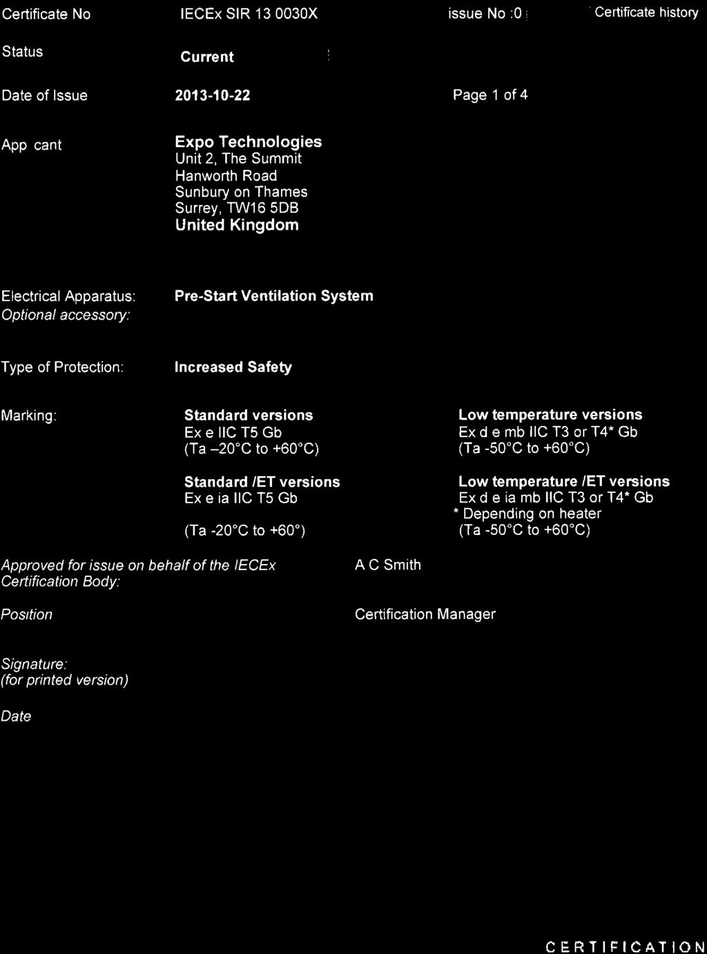
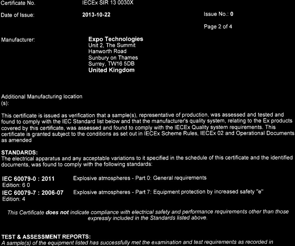
4 Section 1: Pre-Start Ventilation System - General Specification Note: This equipm ent provides ONLY Pre-Start Ventilation, it is not a Purge and Pressurization system Model Number: #PV ss LS N ET PA Other Options PV Sizes - Capacity Tolerance 3PV 500 to 1500 NI/min % 5PV 2000 to 6000 NI/min % 7PV 7000 to NI/min % Timing Method Electronic ET Timer Construction material ss 316 Stainless Steel Starting mode LS Local Start via External Push Button RS Remote Start via Solenoid Valve Ex 24VDC 115VAC 230VAC 24VDC (IS) RS options include a local start Output Signals I S PA PO Suitable for IS circuits "Ex" switches built-in, with "Ex" junction box Pneumatic Output signals Air Inlet Connection Air Supply Air Outlet to Motor 3PV 5PV 7PV 3PV 5PV 7PV N= NPT (F) 3/4" 1" 2" 3/4" 1" 2" A= ANSI 1" 1" N/A 1" 1" N/A G= BSPP 3/4" 1" 2" 3/4" 1" 2" D= DIN DN 20 DN 25 N/A DN 20 DN 25 N/A Reference points and signals: 1/8" NPT(F) Option Codes (Added if applicable) CV Continuous Ventilation HS High Supply Pressure ( 4 to 16 barg) OV Pneumatically Operated Outlet Valve HP High Pressure Hazardous Area Classification FOR ALL OPTIONS COVERED IN THIS MANUAL, (Except Pneumatic Output /PO and LT options) EUROPE - SIRA 13ATEX1083X EN , EN II 2 G Ex e ia IIC T4 Gb Tamb - 20ºC to +60ºC IECEx - IECEx SIR X IEC , IEC Ex e ia IIC T5 Gb Tamb -20ºC to +59ºC FOR ALL OPTIONS (Including Pneumatic Output /PO) EUROPE - EXPO 13MDOC1314 Suitable for use with Ex e & Ex n electrical rotating machines IECEx - EXPO 13MDOC 1313 Suitable for use with Ex e & Ex n electrical rotating machines SPECIAL CONDITIONS FOR SAFE USE / CONDITIONS OF CERTIFICATE (applicable to the options covered by this manual - Do not include Low temperature option). The intended use of this equipment is as a pre-start ventilation system. It is the user responsibility to ensure the correct functionality of the equipment when in use. W hen the equipment is provided with an intrinsically safe solenoid valve, the user must ensure that any associated line inductance is within the parameters of the solenoid valve certificate. Page 1 Expo Technologies UK T: +44 (0) E: sales@expoworldwide.com Expo Technologies US T: +1 (440) E:sales.na@expoworldwide.com ML513 v11 Expo Technologies China T: E: qingdao@expoworldwide.com
5 Ventilation Control Unit Data Ventilated Machine Enclosure: Ex e, Ex n Rotating Electrical Machines. Enclosure Test Pressure: Maximum working = Outlet Valve opening pressure x 1.5. Ventilation Time: User selectable up to 99 minutes (Tolerance: s). Ventilation Initiation: Local Switch (LS): Local Ventilation Switch Push Button Operator. Remote Start (RS) Optional: Ex Solenoid Valve: 24V DC, 110V AC or 230V AC. Indicators: Black / Flashing Yellow : System Ventilating Red / Green : Ventilation Complete. Pneumatic Signals: System Ventilating 4.0 barg (60 psig) 1/8 NPT (F), plug fitted. Ventilation Complete: 4.0 barg (60 psig) 1/8 NPT (F), plug fitted. Ventilation in Progress & Ventilation Complete Contacts: SPNO electrical switch, certified Ex db IIC T6, Contact ratings 250 Vac 4 Amps, AC15. Temperature Limits: -20ºC to +60ºC (T4). -20ºC to +59ºC (T5). Ventilation Flow Sensors: Supply Pressure: Ventilation Flow OK factory set to match ventilation flow rate required. 4 to 10 barg (60 to 145 psig). High Supply Pressure (Optional): 4-16 barg ( psig) for 5PV and 7PV system. Compressed Air Supply: Logic Regulator & Gauge: Air Consumption: Mounting Method Signal Junction Box: Clean, Dry Oil Free Air or inert Gas. Refer to Air Supply Quality section in Installation of the System. Factory set to 4 barg (60 psig) NI/min when not in ventilation mode. Wall mounting straps & spacers. Fix holes as per drawing. ATEX & IECEx certified terminal box. Weight (unpacked): 3PV: 16.5kg (36.3lb) 5PV: 7PV: 20.6kg (45.4lb) 43kg (154lb) Outlet Valve with Integral Spark Arrestor (contains overpressure Relief Valve). 3PV: 5PV: 7PV: Default type: RLV052/ss/PV RLV104/ss/PV RLV200/ss/PV/OV ML513 v11 Expo Technologies UK T: +44 (0) E: sales@expoworldwide.com Expo Technologies US T: +1 (440) E:sales.na@expoworldwide.com Expo Technologies China T: E: qingdao@expoworldwide.com Page 2
6 Outlet Valve lift off pressure: 15 mbarg (6 wg) 15 mbarg (6 wg) Pneumatically Operated Tolerance: +0,-20% +0,-20% Overpressure Relief Valve Lift-Off Pressure: Min: 20 mbarg (8.0 wg) 20 mbarg (8.0 wg) 20 mbarg (8.0 wg) Max: 50 mbarg (20 wg) 50 mbarg (20 wg) 50 mbarg (20 wg) Default: 30 mbarg (12 wg) 30 mbarg (12 wg) 30 mbarg (12 wg) Tolerance: +0, - 20% +0, - 20% +0, - 20% Weight: 4kg (8.8lb) 7kg (15.4lb) 25kg (50.6lb) Available Ventilation Flow Rate 3PV: 5PV: 7PV: 500 NI/min 1000 NI/min 2000 NI/min 3000 NI/min 7000 NI/min 8000 NI/min 1500 NI/min 4000 NI/min NI/min 5000 NI/min NI/min 6000 NI/min NI/min Default: 1000 NI/min 2000 NI/min 7000 NI/min Tolerance: -0, + 20% -0, +20% -0, +20% NOTE: A Solenoid Valve (Optional) may be fitted to allow remote start. Please ensure that one of the solenoid valve options is selected when ordering. See General Specification for Remote Start Options, and Section 10 for the Recommended Spares. Page 3 Expo Technologies UK T: +44 (0) E: sales@expoworldwide.com Expo Technologies US T: +1 (440) E:sales.na@expoworldwide.com ML513 v11 Expo Technologies China T: E: qingdao@expoworldwide.com
7 Section 2: Quick User Guide Operation of the System Once the system is installed correctly, turn on the air supply. Refer to the Commissioning on section 7 for commissioning instructions. Indicator Colour Status System Ventilating Black Not in Ventilation Ventilation Complete Red Power Off Note: User must start the system ventilation cycle by either, pressing the Local Start Push Button or energizing the Solenoid Valve for Remote Start (optional). Ventilation cycle will NOT start just by turning on the air supply. Please refer to relevant drawing number for illustration: 3PV 5PV 7PV XBR-1TD0-015 XBR-1TD0-014 XBR-1TD0-016 **Local Start: To start the ventilation cycle Push and hold the Local Start Push Button until flow is achieved. The System Ventilating LED s will start to flash once air flow is achieved through the machine enclosure system. **Remote Start (Optional) The remote start option will require an Expo approved Solenoid Valve which can be purchased with the PV. Energize the Remote Start Solenoid Valve until flow is achieved in the PV. The System Ventilating LED s will start to flash once air flow is achieved through the machine enclosure system. Ventilation cycle will start for the selected ventilation time. During the ventilation cycle the ventilation gas will exit the enclosure through the spark arrestor in the Outlet Valve. Once the sufficient number of volume changes have completed (defined by the length of the ventilation time period) the system will cease to supply ventilation gas to the enclosure. The system will show Ventilation Complete signal when the ventilation cycle is completed. Note the running time of the ventilation cycle. Indicator Colour Status System Ventilating Yellow Ventilation in progress (Flashing) Ventilation Complete Red Power Off (power to the electrical machine should be off) NOTE: If ventilation cycle fails to start, Open the Ventilation Flow Restrictor until the System Ventilating indicator start to flash. Indicator Colour Status System Ventilating Black Not in Ventilation Ventilation Complete Green Ventilation Cycle Successful (safe to apply power to the electrical machine) ML513 v11 Expo Technologies UK T: +44 (0) E: sales@expoworldwide.com Expo Technologies US T: +1 (440) E:sales.na@expoworldwide.com Expo Technologies China T: E: qingdao@expoworldwide.com Page 4
8 Check that the ventilation time noted is greater or equal to the required ventilation time. The Pre-Start Ventilation will remain in Ventilation Complete mode until either the air supply falls below the minimum supply pressure or the ventilation cycle is reset or re-started either locally or remotely. To reset the Ventilation Complete signal, push the Local Start Push Button or energize the Remote Start Solenoid Valve for one second. If the Local Start Push Button is pushed or the Remote Start Solenoid Valve is energized for more than one second, the PV system will start a new ventilation cycle after resetting. If the system fails to work as expected, refer back to the Installation of the System in section 6. If the problem continues, Refer to the Fault Finding in section 9. If all checks have been done and the system still fails to operate as expected, please contact your local distributor or Expo Technologies. Section 3: Application Suitability The Pre-Start Ventilation systems designed to protect rotating electrical machines, are certified for use in hazardous locations, where the hazardous location is non-mining (above ground) and the hazard is caused by flammable gases, or vapours. The rotating electrical machines must be rated for use in (with the respective markings clearly displayed): Ex e rated rotating electrical machines - ATEX & IECEx Zone 1 or Zone 2 environment. Ex n rated rotating electrical machines - ATEX & IECEx Zone 2 environment. Some High Voltage Ex e and Non Incendive Ex n machines, although certified to Non-Incendive methods of protection can create incendive sparking. These sparks and hot spots are more likely to occur during machine start-up due to the increased loading. The additional hazard that flammable gas may have entered the machine casing is the principle reason for fitting the Pre-Start Ventilation system. See applicable standards such as IEC / EN and IEC / EN Pre-Start Ventilation systems may be used for hazards of any gas group. Apparatus associated with the Pre-Start Ventilation system, such as intrinsically safe signalling circuits and flameproof enclosures containing switching devices may be limited in their gas group. The certification documentation supplied with any of such devices must be checked to ensure their suitability. This system is primarily designed for use with compressed air. Where other inert compressed gases are used (Nitrogen, for example) the user must take suitable precautions so that the build up of the inert gas does not present a health hazard. Consult the Control of Substances Hazardous to Health (COSHH) data sheet for the gas used. Where a risk of asphyxiation exists, a warning label must be fitted to the ventilated enclosure. The following materials are used in the construction of Pre-Start Ventilation Systems. If substances that may adversely affect any of these materials are present in the surrounding environment, please consult Expo Technologies for further guidance. Materials of Construction Stainless Steel Aluminium Acrylic Mild (Carbon) Steel Nylon Silicone Brass Polyurethane Neoprene ABS Polycarbonate Polyester (glass filled) Page 5 Expo Technologies UK T: +44 (0) E: sales@expoworldwide.com Expo Technologies US T: +1 (440) E:sales.na@expoworldwide.com ML513 v11 Expo Technologies China T: E: qingdao@expoworldwide.com
9 Note: This is NOT an Ex p Purge & Pressurization control system and is not designed to maintain an overpressure within the machine casing. Section 4: Description and Principle of Operation The Pre-Start Ventilation System applies specifically to electrical machines e.g motors and generators that are already (or in the process of) being certified/approved as increased Safety (Ex e) or Non Incendive Ex n. Prior to switching on the power (either Locally or Remotely) to the electrical equipment, the machine must be ventilated to remove any flammable gas that might have entered the enclosure machine. Pre-Start Ventilation is the process of removal of contaminated air and replacement with air (or inert gas) known to be free from flammable gas prior to machine start-up. The duration of the ventilation cycle process is normally ascertained by performing a ventilation test. The air supply can be turned off after the Ventilation Cycle has been completed. No leakage compensation is required. The principle of Pre-Start Ventilation is as follows: Clean compressed air or inert gas is drawn from a non-hazardous location. The interior of the machine is pre-ventilated to remove any hazardous gas. Measure the flow of ventilation air at a defined outlet. Positive pressure in the enclosure of the electrical machine prevents the hazardous gas from the environment to enter the enclosure during the ventilation cycle. Local Operation Local operation is selected when the remote operation option is either not available, or is de-energized. Turning on the air supply alone will not activate a ventilation cycle. The PV system will not start until the ventilation cycle is activated by operating the Local Start Push Button. To start ventilation cycle, push and hold the Local Start Push Button until flow is achieved. The flow in the enclosure will be indicated by the flashing Yellow indicator System Ventilating LED s. The ventilation cycle will then start. When the required ventilation flow from the outlet valve level has been attained, visual indicator, visual indicator and volt free (dry) contact will indicate System Ventilating. The ventilation will continue for the selected ventilation time. At the end of the ventilation time the system will show Green indicator Ventilation Complete, pneumatic signal and or another set of volt free (dry) contacts. To reset the Ventilation Complete signal, push the Local Start Push Button for one second. If held for longer than one second, the system will start a new ventilation cycle after resetting. Remote control operation (Optional) The PV system can be operated remotely to ventilate the rotating electrical machine before use. Note that the PV system will not start the ventilation cycle automatically when the air supply is turned on. User must activate the ventilation cycle by energizing the Remote Start Solenoid Valve. The appropriate remote control option if selected must be factory fitted to the PV system. For remote control operation: ML513 v11 Expo Technologies UK T: +44 (0) E: sales@expoworldwide.com Expo Technologies US T: +1 (440) E:sales.na@expoworldwide.com Expo Technologies China T: E: qingdao@expoworldwide.com Page 6
10 Start the ventilation cycle by energizing the Remote Start Solenoid Valve until flow is achieved in the PV system. The flow in the enclosure will be indicated by the flashing Yellow indicator System Ventilating. When the required ventilation flow from the outlet valve level has been attained, visual indicator, pneumatic signal or a volt free (dry) contact will indicate System Ventilating. The ventilation will continue for the selected ventilation time. At the end of the ventilation time the system will show Green indicator Ventilation Complete, pneumatic signal and or another set of volt free (dry) contacts. To reset the Ventilation Complete signal, energize the Remote Solenoid Valve for one second. If held for longer than one second, the system will start a new ventilation cycle after resetting. For Local Start or Remote Start operation; when the pressure in the enclosure reaches the liftoff pressure of the Outlet Valve, this opens and allows airflow through the machine casing. Note: For 7PV Pneumatically Operated Valve, the valve will open as flow enters the machine casing. The Overpressure Relief Valve can also open during fault conditions if the pressure rises inside the machine to or above the opening pressure. Two pipes connects the Outlet Valve to a Ventilation Flow Sensor in the PV system to measure the differential pressure across the orifice plate. When the pressure rises above the factory set pressure flow rate, the ventilation Flow Sensor will activate the timing circuit. The timer will operate for the specified ventilation time to ventilate the machine if the air flow rate does not fall below the required flow rate. When the required ventilation flow level is attained, the visual indicator System Ventilating will start flashing Yellow, and the pneumatic output or volt-free contact will be activated. At the end of the timed ventilation cycle, the air flow to the machine will be turned off by the PV system. The pressure within the machine falls to atmospheric, and the Outlet Valve closes. Within the PV system, the Green Ventilation Complete indicator, pneumatic signal & a volt free (dry) contact will close giving permission to start the machine switchgear. Provided that the air supply to the system is not interrupted, the system will remain in this condition unless the Local Start or Remote Start Solenoid Valve is activated for one second causing the system to reset. Page 7 Expo Technologies UK T: +44 (0) E: sales@expoworldwide.com Expo Technologies US T: +1 (440) E:sales.na@expoworldwide.com ML513 v11 Expo Technologies China T: E: qingdao@expoworldwide.com


11 Start Operator (Local or Remote) System Ventilating Contacts Ventilation Complete (Permissive Start) User Selectable 1 to 99 minutes Ventilation Flow Rate Ventilation Flow Ventilation Flow During CV Option Initial Ventilation Cycle Flow Achieved/ Timing Starts Ventilation Complete Pre-Start Ventilation Flow Chart Section 5: Main Components Refer to section 12 Drawings and Diagrams list for relevant PV system General Arrangement for components numbering. Air Supply Filter The unit is provided with a 40-micron water / dust filter element as a precaution but air supply should be to the quality as stated in the Air Supply paragraph found in the Installation of the System section. Ventilation Flow Regulator The Ventilation Flow Regulator is a 0-7 barg Pressure Regulator and is User Adjustable between 0-4 barg (clockwise to increase flow) to control the total ventilation flow supplied to the enclosure during ventilation. The total ventilation flow is the (Ventilation Flow rate at the Outlet Valve +10%) + the leakage of the machine casing. Ventilation Control Pilot Operated Regulator This regulator controls the ventilation air supply to the enclosure according to the supply from the ventilation flow regulator and is automatically closed after the ventilation time has been completed. Logic Air Supply Regulator This device provides the system with a stable logic pressure supply for consistent operation. The pressure level of 4.0 barg (60 psig) is factory set and can be verified by means of the integral pressure gauge. It should only be adjusted if the gauge indicates that the regulated pressure is incorrect. This should indicate no more than 4.0 barg (60 psig). During ventilation you may notice the pressure drop down to 3.0 barg (45 psig). ML513 v11 Expo Technologies UK T: +44 (0) E: sales@expoworldwide.com Expo Technologies US T: +1 (440) E:sales.na@expoworldwide.com Expo Technologies China T: E: qingdao@expoworldwide.com Page 8
12 Visual indicators Visual indicators are fitted to provide local status information to the operator: Ventilation in Progress Indicator Black Ventilation flow too low (or not in Ventilation mode) Yellow (flashing) Ventilation flow above the minimum (Ventilation in Progress) Ventilation Complete Indicator Red Power Off (power to the electrical machine should be off) Green Ventilation Cycle Successful (safe to apply power to the electrical machine) /PA Terminal Box Increased Safety Ex e IIC T5 Gb Ex tb IIIC T100ºC Db IP66 Tamb -20ºC to +55ºC Ex e IIC T4 Gb Tamb -20ºC to +60ºC The Terminal Box is increased safety (Ex e) certified and incorporates the terminal connection points for the switches and solenoid valve (when Remote Start is included). All contacts provided are volt free (dry). Cable entry methods (for example conduit or cable glands) must be certified to IECEx and ATEX standards. The main requirement is that IP66 (or better) ingress protection must be provided by use of seals or washers. /IS Intrinsically Safe (Ex i) The output signals Ventilation in Progress and Ventilation Complete are available as volt-free contacts in blue terminals, for connection to Intrinsically Safe circuits. The terminal box has an isolation partition to keep the separation between I.S. circuits and non-i.s. circuits, when the solenoid valve is not I.S. /PO Pneumatic Output Signals The output signals Ventilation in Progress and Ventilation Complete are 4 barg (60 psig) pneumatic signal available for connection to 1 / 8 NPT Female bulkheads. Connect these signals to external pressure switches. Outlet Valve This device has several functions: The Outlet Valve unit is calibrated to open when the Ventilated Enclosure pressure exceeds the set point. It contains a Spark Arrestor designed to prevent the emission of arcs, sparks and incandescent particles produced by normal operation or electrical fault within the machine. It measures the differential pressure across the outlet orifice during ventilation flow. The measurement figure indicates when the required flow rate is achieved and timing of the ventilation cycle can start. It contains the overpressure Relief Valve. To achieve effective Ventilation Flow, the point where air enters and exits the machine should normally be at opposite ends of the enclosure. The Outlet Valve unit must be mounted vertically and there should be a minimum clearance of 300 mm (12 ) around the spark arrestor. The Outlet Valve have user selectable orifice plates. These allow the flow rate to be selected by the user without modification to the PV system. It is important that the interior and exterior of the spark arrestor is kept clean and debris is not allowed to accumulate. In particular the exterior of the spark arrestor should not be painted or blocked in any way. Page 9 Expo Technologies UK T: +44 (0) E: sales@expoworldwide.com Expo Technologies US T: +1 (440) E:sales.na@expoworldwide.com ML513 v11 Expo Technologies China T: E: qingdao@expoworldwide.com
13 Section 6: Installation of the System The Pre-Start Ventilation System must be installed by a competent person in accordance with relevant standards, such as IEC/EN and The installation must strictly adhere to the current standards that applies to the installation of Intrinsically Safe, Increased Safety and Type n apparatus. Copies of the Current Standard can be purchased from Expo Technologies or B.S.I or relevant local code / Standard. The Pre-Start Ventilation system should be installed either directly on, or close to the machine. It should be installed such that the system indicators and certification labels are in view. All parts of the system carry a common serial number. If installing more than one system, ensure that this commonality is maintained within each system installed. Air Supply Quality The Pre-Start Ventilation System should be connected to a protective gas supply, which is suitable for ventilation. The supply pipe connections to the Pre-Start Ventilation System are: 3PV 5PV 7PV 1/2 NPT (F) 1 NPT (F) 2 NPT (F) The size of the input pipe should be appropriate for the maximum input ventilation flow rate for the application. The air supply must be regulated at a pressure less than the maximum stated inlet pressure. The air supply must be: clean, non-flammable and from a non-hazardous location. It must comply with BS ISO : 2001 Class or equivalent local standards. This is typically referred to as Instrument Air Quality. Although equipment will operate with lower air quality, the operational life of the system will be adversely affected. The equipment that is being protected by the Pre-Start Ventilation may also suffer because of poor air quality. Instrument Air Quality Solid Particles 0.5 μm < particle size 1 μm, maximum 1000 particles / m 3 Residual Water 1μm maximum density, +3 o C* pressure dewpoint Oil Content 0.01 mg / m 3 concentration total oil * For applications where T amb 0 o C, the air supply should be Class with humidity of -70 o C pressure dewpoint. When an inert gas is being used to supply the ventilation system, risk of asphyxiation exists. Refer to Application Suitability section. Before connecting the air supply to the Pre-Start Ventilation System, the supply pipe work should be flushed through with instrument quality air to remove any debris that may remain in the pipes. This must be carried out for at least 10 seconds for every metre of supply pipe. The ventilation air from the Pre-Started Ventilation system should be piped within the machine to ensure ventilation of potential dead air spots. Warning: The system is fitted with an internal regulator factory set to 4 barg (60 psig) feeding the logic air supply regulator. The correct logic supply pressure is vital to the reliability and calibration of the Pre-Start Ventilation System, therefore should NOT be adjusted. ML513 v11 Expo Technologies UK T: +44 (0) E: sales@expoworldwide.com Expo Technologies US T: +1 (440) E:sales.na@expoworldwide.com Expo Technologies China T: E: qingdao@expoworldwide.com Page 10
14 Pipe Work If the Pre-Start Ventilation is not connected directly to the machine enclosure, pipe work and fittings used to connect the PV system to the machine enclosure should be either metallic or appropriate to the environment into which the system is installed. No valve may be fitted in any signal pipe connecting the PV system to the machine enclosure. This pipe work must be fitted in accordance with local codes of practice where relevant. Multiple Enclosures This system is suitable for the ventilation of the primary enclosure and its associated terminal boxes. Power Supplies and their Isolation All power entering the rotating electrical machine must have a means of isolation. This requirement also applies to any external power sources that are connected to the equipment such as volt-free (dry) contacts within the rotating electrical machine. The electrical installation must conform to the local codes of practice. Exception Power to Intrinsically Safe apparatus, or apparatus that is already suitable for use in hazardous locations need not be isolated by the Pre-Start Ventilation System. In all cases the user must control the application and the isolation of power to the rotating electrical machine after the Pre-Start Ventilation System shows the Ventilation Complete Green signal. Section 7: Commissioning Commissioning the System Refer to the General Arrangement (GA) drawing for the Pre-Start Ventilation system option. If, after commissioning, the system does not perform as expected, refer to the Fault Finding Section. Follow these steps: 1. Disconnect the air supply pipe from the inlet to the PV System. 2. Flush the pipe through with instrument quality air to remove any debris. This must be carried out for at least 10 seconds for every metre of supply pipe. 3. Check all connections between the PV system and the Outlet Valve. The Outlet Valve Unit must be fitted correctly with clear path to the ventilation exhaust. 4. Close and re-open the internal shut off valve. See No. 5 in the GA drawing. 5. Check that the internal logic pressure gauge reads 4.0 barg (60 psig). See No. 4 in the GA drawing. 6. Start the ventilation cycle by pushing the Local Start Push Button momentarily until flow is achieved. Or use the Remote Start facility where fitted. 7. The ventilation timer will start as soon as the System Ventilating indicator turn from Black to flashing Yellow. 8. Check the time delay between the System Ventilating indicator start flashing Yellow, and the Ventilation Complete indicator turning from Red to Green. Ventilation time should not be less than the minimum required. Times in excess of the minimum are permitted. Page 11 Expo Technologies UK T: +44 (0) E: sales@expoworldwide.com Expo Technologies US T: +1 (440) E:sales.na@expoworldwide.com ML513 v11 Expo Technologies China T: E: qingdao@expoworldwide.com
15 9. If the System Ventilating indicator does not flash Yellow, this indicates low ventilation flow. This can happen with a machine housing with greater than expected leakage. Increase the ventilation pressure. 10.To correct this, push and hold the Local Start Push Button. 11.Very slowly, open (clockwise) the Ventilation Flow Regulator (See No. 8 in the GA drawing), until the indicator flashes Yellow. DO NOT open too quickly as this can allow too much air and over pressurize the enclosure. 12.If after the flow regulator is fully open (the pressure gauge read 4mbar), and the Ventilation in Progress indicator does not flash Yellow, refer to next page on Procedure for increasing air flow. When a full ventilation cycle is successfully completed, the System Ventilating indicator will turn from flashing Yellow to Black. At the same time the Ventilation Complete indicator will turn from Red to Green. The appropriate pneumatic or electrical signals will coincide with the changes of indicator status. Once the ventilation time is completed, the ventilation air flow to the machine will stop and the Ventilation Complete signal will activate. The system will remain in this mode until the system is either reset or re-started, or the air supply to the system is isolated. To reset the Ventilation Complete signal, push the Local Start Push Button or energise the Remote Start Solenoid Valve for one second. To re-start a ventilation cycle again, push and hold the Local Start Push Button or the Remote Start facility until the System Ventilating LED s begin to flash. Procedure for increasing air flow It is possible for the enclosure of the rotating electrical machine to have a higher leakage rate than expected, which may affect the PV system s ability to achieve sufficient air flow to start the ventilation cycle. See table below to identify if the PV system require the below procedure for removing the fitted restrictor to increase air flow through the system. Note: This procedure should be carried out by a competent engineer. System Orifice in system Outlet Valve (required flow) Remove Restrictor (Yes/No) 3PV 1500 NI/min Yes (If unable to achieve sufficient flow to start electronic timer). 5PV 6000 NI/min Yes 7PV N/A N/A Necessary spanner (wrench) sizes Components 3PV 5PV Locknut 32mm 42mm ML513 v11 Expo Technologies UK T: +44 (0) E: sales@expoworldwide.com Expo Technologies US T: +1 (440) E:sales.na@expoworldwide.com Expo Technologies China T: E: qingdao@expoworldwide.com Page 12


 20 8398 8011 E:")
16 Components 3PV 5PV Union Nut 40mm 54mm Union 26mm 39mm Use the spanner (wrench) to loosen the locknut. It should go back 15-20mm. Loosen the union nut and move it back towards the locknut as shown Pull back the right hand half of the union 5-10mm. The orifice restrictor is in the middle. Remove the restrictor. Wind back the right hand union half towards the left union half. Note: It is very important to fit the two halves together tightly to avoid leakage. Lock the two union halves together with the union nut. Wind back the locknut to it former position. Page 13 ML513 v11 Expo Technologies UK T: +44 (0) E: Expo Technologies US T: +1 (440) Expo Technologies China T: E:
17 Section 8: Maintenance of the System General maintenance The maintenance of the system outlined in this manual should be supplemented with any additional requirements set out in appropriate local codes of practice. The following checks should be carried out every 6 36 months dependent on environment according to IEC / EN Tests outlined in the Detailed Commissioning section. Ensure that the Outlet Valve Unit is free from contamination prior to making any adjustment. To do this: Remove large cover plate using a 10 mm spanner (wrench). Check that the interior and all components are clean and free from contamination. Replace large cover plate. Check the condition of the air supply filter element. Clean or replace as necessary. The following additional checks are recommended at least every 3 years: Check that: Apparatus is suitable for use in the hazardous location. There are no unauthorised modifications. The air supply is not contaminated. The System Ventilating and System Ventilation Complete signals function correctly. Approval labels are legible and not damaged. Adequate spares are carried. The action on pressure failure is correct. Maintenance of Electronic Timer This must be carried out every 3 years. The intrinsically safe battery pack associated with the electronic timer should be replaced and the commissioning tests repeated. After the timing phase has elapsed, the battery may be hot-swapped in the hazardous location without affecting the operation of the Pre-Start Ventilation System ML513 v11 Expo Technologies UK T: +44 (0) E: sales@expoworldwide.com Expo Technologies US T: +1 (440) E:sales.na@expoworldwide.com Expo Technologies China T: E: qingdao@expoworldwide.com Page 14
18 Section 9: Fault Finding General Information If there are any problems that cannot be corrected using one of the methods described, please call Expo or your supplier for further assistance. If the system is less than 12 months old, parts under warranty should be returned to Expo for investigation. A full report of the fault and the system serial number should accompany the parts. It is common for problems with the Pre-Start Ventilation System to be caused by contamination of the air supply with oil, water or dirt. To prevent these problems, the air supply must contain a dust filter and a water filter. This will ensure that the air is instrument quality and protect both the ventilation system and the equipment being ventilated. This filtration system is not provided by Expo and must be sourced separately. Contamination can enter the system from a number of sources. To prevent this, it is essential that the procedures described in the Installation section are carried out prior to first use of the system. These procedures should also be carried out following any disconnection and re-connection of the pipe work. Failure to perform these procedures may cause damage to the system that will not be covered by the warranty. The system has been designed for ease of fault finding and the many of the components fitted are plug-in or chassis mounted. Check components by substitution only after establishing that such action is necessary. Before carrying out the fault finding procedures, ensure that: Both the main air pressure to the system and the regulated pressure to the logic manifold are as specified on the settings sheet. Air pressure does not drop below the minimum supply pressure during ventilation; the majority of faults reported are due to insufficient air supply during the ventilation cycle. Pre-Start Ventilation System has sufficient flow but no System Ventilating signal. Fault Location Cause Solution Battery Pack. The battery pack is discharged. Battery needs replacement. Consult Expo Technologies. System Ventilating switch. Stroke actuator faulty. Ex d system ventilating switch is faulty. Check the actuation of switch by the Short Stroke Actuator for Ex d Switch. Refer to relevant General Arrangement (GA) drawing. If Stroke Actuator is not moving while the system is ventilating, the actuator may require replacement. Consult Expo Technologies. If Stroke Actuator is working, check that the switch is closing. If it is not closing, it needs to be replaced. If it is closing but no signal is present, the switch needs replacement. Consult Expo Technologies Electronic Timer The Electronic Timer is faulty Needs replacement. Consult Expo. This should be done by a competent Service Engineer. Page 15 Expo Technologies UK T: +44 (0) E: sales@expoworldwide.com Expo Technologies US T: +1 (440) E:sales.na@expoworldwide.com ML513 v11 Expo Technologies China T: E: qingdao@expoworldwide.com
19 Ventilation does not start or fails to complete This is common due to the smaller pipe diameter or smaller compressor. Fault Location Cause Solution Air Supply Pressure Machine could have a greater leakage rate than expected Ventilation Time Insufficient Air supply pressure fall below 4 barg (60 psig). Insufficient air supply to rotating electrical machine enclosure. Check that the air supply pressure is not below the specified minimum pressure during ventilation. Increase air pressure. The pressure gauge should be above 4 barg (60 psig) during ventilation. or replace main air filter. Consult Expo Technologies. Slowly turn the Ventilation Flow Regulator to increase the air flow. Do this until the Ventilation in Progress indicator is activated. Indicator should turn from Black Flashing Yellow This can occur if the Electronic Timer Selector Switches have not been set correctly. to This indicates correct Ventilation Flow. If the problem is not solved, refer to the Procedure for increasing air flow in the Commissioning section. Remote Solenoid Valve Not functioning Check all connections from the PV system to the Remote Start control, continuity and supply voltage where possible. Fault Location Cause Solution Electronic Timer Selector Switch Make sure all connections are secure and terminated correctly. If all these appear to be correct, then check the operation of the system by using the Local Start Push Button. If the Local Start Push Button successfully starts a ventilation cycle, the Solenoid Valve needs replacement. Not set correctly Make sure the Electronic Timer Selector Switch is correct to the required setting. Electronic Timer is faulty Replacement necessary This should be fitted by a competent Service Engineer. ML513 v11 Expo Technologies UK T: +44 (0) E: sales@expoworldwide.com Expo Technologies US T: +1 (440) E:sales.na@expoworldwide.com Expo Technologies China T: E: qingdao@expoworldwide.com Page 16
20 Flow Sensor Calibration Contact Expo Technologies for new Ventilation Flow Sensor if the sensor is out of calibration. Section 10: Recommended Spares List Part Number Description HF1-A03N-008 Filter kit for HF1-A03N-009 filter - size 3 HF1-A03N-007 Filter kit for HF1-A03N-006 filter - size 5 HF1-A03N-002 Filter kit for HF1-A03N-001 filter - size 7 S0191/025 Ex d II switch SPNO S0030/606 Ventilation Flow sensor, must be factory set to the value as stated on the Customer Test and Inspection Sheet ETM-IS IS battery pack for Electronic Timer KPV-RS01 KPV-RS02 KPV-RS03 KPV-RS10 KPV-RS11 24VDC Remote Start Solenoid Kit 110VAC Remote Start Solenoid Kit 230VAC Remote Start Solenoid Kit 12VDC (IS) Remote Start Solenoid Kit 24VDC (IS) Remote Start Solenoid Kit Section 11: Glossary Acronym PV ET LS RS IS PA OV PO Definition Pre-Start Ventilation system Electronic Timer Local Start Pushbutton Remote Start (Solenoid valve) Intrinsically Safe Permissive Alarm Pneumatically Operated Outlet Valve Pneumatic Output Page 17 Expo Technologies UK T: +44 (0) E: sales@expoworldwide.com Expo Technologies US T: +1 (440) E:sales.na@expoworldwide.com ML513 v11 Expo Technologies China T: E: qingdao@expoworldwide.com
21 Section 12: Drawings and Diagrams PV Title Drawing Number Number of Sheets Pre-Start Ventilation system 3PV XBR-1TD Pre-Start Ventilation system 5PV XBR-1TD Pre-Start Ventilation system 7PV XBR-1TD VP and 5PV Typical PV Hook Up PV-HU 1 7PV Typical Hook up drawing 7PV-HU 1 PV P and I Diagram PV-PI 1 PV Ex e Terminal Box Layout AGE-WC Indicator Displays/Switch Sequence SD Section 13: Certification Download the certificates at Component Certificate Number Ventilation System ATEX Certificate SIRA 13ATEX1083X IECEx Certificate SIR X EXPO EXPO 13MDOC1314 EXPO 13MDOC1313 COC SC024 MIU/e Ex e Terminal Box ATEX Certificate ITS 10ATEX37092X IECEx Certificate IECEx ITS X Electronic Timer ATEX Certificate FM 10 ATEX0003X IECEx Certificate IECEx FME X Electronic Switch Ex d limit switch IECEx EPS X Ex d limit switch EPS 14 ATEX 1766 X Solenoid Valve Ex mb RS00/RS01/RS02/RS03 IECEx SIR X SIRA BAS98ATEX2168X Ex i RS10/RS11 IECEx INE X INERIS 03ATEX0249X Ex d RS20/RS21/RS22 LCIE 00ATEX6008X IECEx LCI X ML513 v11 Expo Technologies UK T: +44 (0) E: sales@expoworldwide.com Expo Technologies US T: +1 (440) E:sales.na@expoworldwide.com Expo Technologies China T: E: qingdao@expoworldwide.com Page 18
22
23
24
25
26
27
28

29
30
31
32
33
34
35

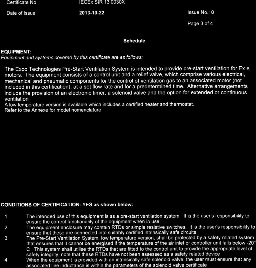
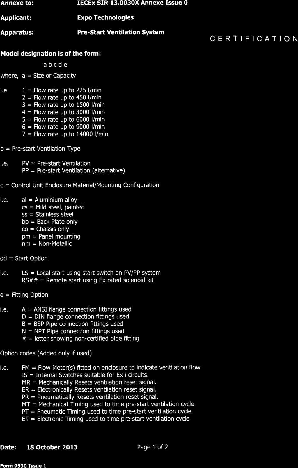
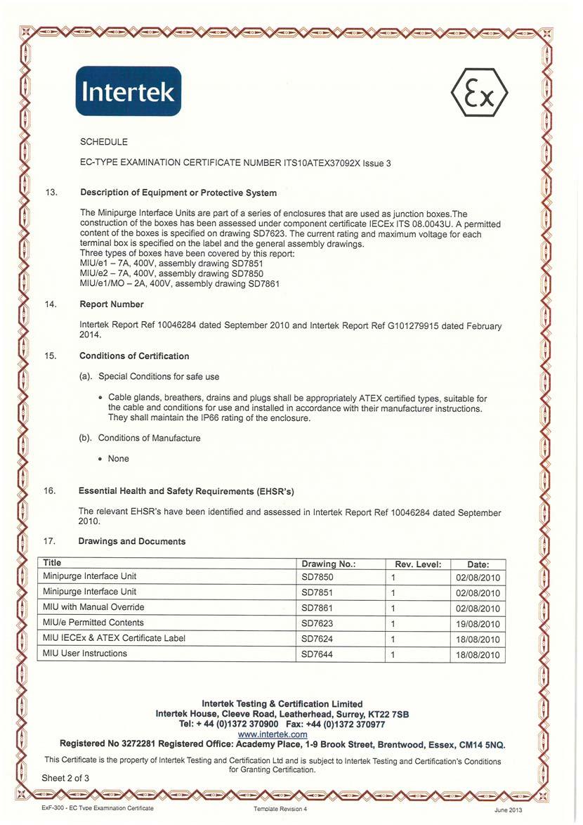
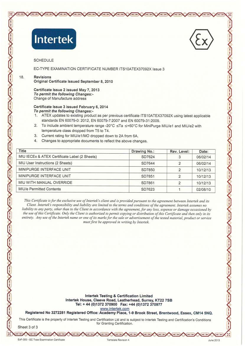
36 CERT IFICAT ION 1 EC TYPE-EXAMINATION CERTIFICATE 2 Equipment intended for use in Potentially Explosive Atmospheres Directive 94/9/EC 3 Certificate Number: Sira 13ATEX1083X Issue: 0 4 Equipment: Pre-Start Ventilation System 5 Applicant: Expo Technologies 6 Address: Unit 2, The Summit Hanworth Road Sunbury on Thames Surrey, TW16 5DB 7 This equipment and any acceptable variation thereto is specified in the schedule to this certificate and the documents therein referred to. 8 Sira Certification Service, notified body number 0518 in accordance with Article 9 of Directive 94/9/EC of 23 March 1994, certifies that this equipment has been found to comply with the Essential Health and Safety Requirements relating to the design and construction of equipment intended for use in potentially explosive atmospheres given in Annex II to the Directive. The examination and test results are recorded in the confidential reports listed in Section Compliance with the Essential Health and Safety Requirements, with the exception of those listed in the schedule to this certificate, has been assured by compliance with the following documents: EN :2012 EN :2007 The above list of documents may detail standards that do not appear on the UKAS Scope of Accreditation, but have been added through Sira s flexible scope of accreditation, which is available on request. 10 If the sign X is placed after the certificate number, it indicates that the equipment is subject to special conditions for safe use specified in the schedule to this certificate. 11 This EC type-examination certificate relates only to the design and construction of the specified equipment. If applicable, further requirements of this Directive apply to the manufacture and supply of this equipment. 12 The marking of the equipment shall include the following: Standard versions Low temperature versions II 2 G II 2 G Ex e IIC T5 Gb Ex d e mb IIC T3 or T4* Gb (Ta 20 C to +60 C) (Ta -50 C to +60 C) Standard /ET versions Low temperature /ET versions II 2 G II 2 G Ex e ia IIC T5 Gb Ex d e ia mb IIC T3 or T4* Gb (Ta -20 C to +60 ) (Ta -50 C to +60 C) * Depending on heater Project Number A C Smith Certification Manager This certificate and its schedules may only be reproduced in its entirety and without change. Form 9400 Issue 3 Page 1 of 4 Sira Certification Service Rake Lane, Eccleston, Chester, CH4 9JN, England Tel: +44 (0) Fax: +44 (0) info@siracertification.com Web: CERT IFICAT ION SCHEDULE EC TYPE-EXAMINATION CERTIFICATE Sira 13ATEX1083X Issue 0 13 DESCRIPTION OF EQUIPMENT The Expo Technologies Pre-Start Ventilation System is intended to provide pre-start ventilation for Ex e motors. The equipment consists of a control unit and a relief valve, which comprise various electrical, mechanical and pneumatic components for the control of ventilation gas to an associated motor (not included in this certification), at a set flow rate and for a predetermined time. Alternative arrangements include the provision of an electronic timer, a solenoid valve and the option for extended or continuous ventilation. A low temperature version is available which includes a certified heater and thermostat. Model designation is of the form: a b c d e where, a = Size or Capacity i.e. 1 = Flow rate up to 225 l/min 2 = Flow rate up to 450 l/min 3 = Flow rate up to 1500 l/min 4 = Flow rate up to 3000 l/min 5 = Flow rate up to 6000 l/min 6 = Flow rate up to 9000 l/min 7 = Flow rate up to l/min b = Pre-start Ventilation Type i.e. PV = Pre-start Ventilation PP = Pre-start Ventilation (alternative) c = Control Unit Enclosure Material/Mounting Configuration i.e. al = Aluminium alloy cs = Mild steel, painted ss = Stainless steel bp = Back Plate only co = Chassis only pm = Panel mounting nm = Non-Metallic d = Start Option i.e. LS = Local start using start switch on PV/PP system RS## = Remote start using Ex rated solenoid kit e = Fitting Option i.e. A = ANSI flange connection fittings used D = DIN flange connection fittings used B = BSP Pipe connection fittings used N = NPT Pipe connection fittings used # = letter showing non-certified pipe fitting This certificate and its schedules may only be reproduced in its entirety and without change. Form 9400 Issue3 Page 2 of 4 Sira Certification Service Rake Lane, Eccleston, Chester, CH4 9JN, England Tel: +44 (0) Fax: +44 (0) info@siracertification.com Web:
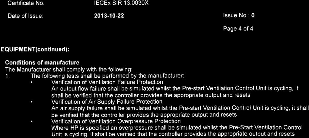
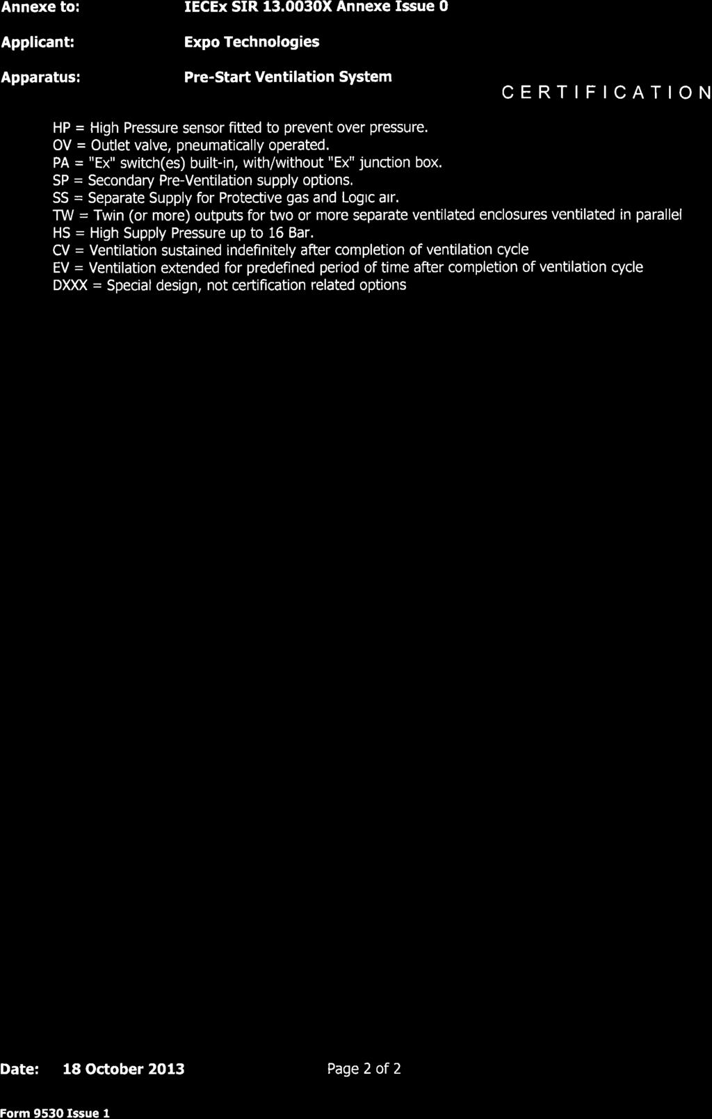
37 CERT IFICAT ION SCHEDULE EC TYPE-EXAMINATION CERTIFICATE Sira 13ATEX1083X Issue 0 Option codes (Added only if used) i.e. FM = Flow Meter(s) fitted on enclosure to indicate ventilation flow IS = Internal Switches suitable for Ex i circuits. MR = Mechanically Resets ventilation reset signal. ER = Electronically Resets ventilation reset signal. PR = Pneumatically Resets ventilation reset signal. MT = Mechanical Timing used to time pre-start ventilation cycle PT = Pneumatic Timing used to time pre-start ventilation cycle ET = Electronic Timing used to time pre-start ventilation cycle HP = High Pressure sensor fitted to prevent over pressure. OV = Outlet valve, pneumatically operated. PA = "Ex" switch(es) built-in, with/without "Ex" junction box. SP = Secondary Pre-Ventilation supply options. SS = Separate Supply for Protective gas and Logic air. TW = Twin (or more) outputs for two or more separate ventilated enclosures ventilated in parallel. HS = High Supply Pressure up to 16 Bar. CV = Ventilation sustained indefinitely after completion of ventilation cycle EV = Ventilation extended for predefined period of time after completion of ventilation cycle DXXX = Special design, not certification related options 14 DESCRIPTIVE DOCUMENTS 14.1 Drawings Refer to Certificate Annexe Associated Sira Reports and Certificate History Issue Date Report number Comment 0 11 October 2013 R29083A/00 The release of the prime certificate. 15 SPECIAL CONDITIONS FOR SAFE USE (denoted by X after the certificate number) 15.1 The intended use of this equipment is as a pre-start ventilation system. It is the user s responsibility to ensure the correct functionality of the equipment when in use The equipment enclosure may contain RTDs or simple resistive switches. It is the user s responsibility to ensure that these are connected into suitably certified intrinsically safe circuits The Pre-Start Ventilation System, low temperature version, shall be protected by a safety related system that ensures that it cannot be energised if the temperature of the air inlet or controller unit falls below -20 C. This system shall utilise the RTDs that are fitted to the control unit to provide the appropriate level of safety integrity, i.e. a level of operational safety of Cat 3 according to EN for ATEX Category 2 (Zone 1) applications; note that these RTDs have not been assessed as a safety related device in accordance with EHSR 1.5 of Directive 94/9/EC When the equipment is provided with an intrinsically safe solenoid valve, the user must ensure that any associated line inductance is within the parameters of the solenoid valve certificate. This certificate and its schedules may only be reproduced in its entirety and without change. Form 9400 Issue3 Page 3 of 4 Sira Certification Service Rake Lane, Eccleston, Chester, CH4 9JN, England Tel: +44 (0) Fax: +44 (0) info@siracertification.com Web: CERT IFICAT ION SCHEDULE EC TYPE-EXAMINATION CERTIFICATE Sira 13ATEX1083X Issue 0 16 ESSENTIAL HEALTH AND SAFETY REQUIREMENTS OF ANNEX II (EHSRs) The relevant EHSRs that are not addressed by the standards listed in this certificate have been identified and individually assessed in the reports listed in Section CONDITIONS OF CERTIFICATION 17.1 The use of this certificate is subject to the Regulations Applicable to Holders of Sira Certificates Holders of EC type-examination certificates are required to comply with the production control requirements defined in Article 8 of directive 94/9/EC The following tests shall be performed by the manufacturer: Verification of Ventilation Failure Protection An output flow failure shall be simulated whilst the Pre-start Ventilation Control Unit is cycling, it shall be verified that the controller provides the appropriate output and resets. Verification of Air Supply Failure Protection An air supply failure shall be simulated whilst the Pre-start Ventilation Control Unit is cycling, it shall be verified that the controller provides the appropriate output and resets. Verification of Ventilation Overpressure Protection Where HP is specified an overpressure shall be simulated whilst the Pre-Start Ventilation Control Unit is cycling, it shall be verified that the controller provides the appropriate output and resets. This certificate and its schedules may only be reproduced in its entirety and without change. Form 9400 Issue3 Page 4 of 4 Sira Certification Service Rake Lane, Eccleston, Chester, CH4 9JN, England Tel: +44 (0) Fax: +44 (0) info@siracertification.com Web:
38 Certificate Annexe Certificate Number: Sira 13ATEX1083X Equipment: Pre-Start Ventilation System Applicant: Expo Technologies CERT IFICAT ION Issue 0 Drawing Sheets Rev. Date (Sira Stamp) Title SD to Sep 13 Low Temperature Housing SD of Sep 13 System Low Temp. Wiring (Typical) SD of Sep 13 Spark Arrestor SD of Sep 13 Differential Flow Monitor SD to Sep 13 RLV Configurations SD to Sep 13 Ventilation Complete Reset Options MR ER & PR for PV System SD to Sep 13 Sequence Diagram for PV/PP System SD of Sep 13 Pre-Start Ventilation Housing SD of Sep 13 Option IS Internal Switches for PV/PP System SD of Sep 13 Secondary Pre-Ventilation SP & Twin Output TW for PV System SD to Sep 13 Pre-Start Ventilation Model Numbers SD to Sep 13 Circuit Diagram for PV/PP System SD of Sep 13 Separate Supply SS Option for PV System SD of Sep 13 High Pressure Option HP SD of Sep 13 OV Option for PV System SD of Sep 13 Timing Options for PV System ET MT PT SD to Sep 13 Certification Label This certificate and its schedules may only be reproduced in its entirety and without change. Form 9400 Issue3 Page 1 of 1 Sira Certification Service Rake Lane, Eccleston, Chester, CH4 9JN, England Tel: +44 (0) Fax: +44 (0) info@siracertification.com Web:


39


40

41
42 (1) Declaration of Conformity (2) Expo Technologies Document Number EXPO 13MDOC1314 Issue 1 (3) This declaration is issued for the Pre-Start Ventilation Systems Types 4PP, 6PP, 7PP, 3PV, 5PV & 7PV (4) Manufacturer: Expo Technologies Ltd Unit 2, The Summit Hanworth Road Sunbury on Thames TW16 5DB U.K. (5) Pre-Start Ventilation Systems, types 4PP, 6PP, 7PP, 3PV, 5PV or 7PV, including all option models, are designed to protect rotating electrical machines, by removing any explosive gases which may ignite during the start-up cycle. (6) The system is suitable for use with Ex e rotating electrical machines in accordance with EN :2015. (7) Expo Technologies declares that the Pre-Start Ventilation System is fully constructed of pneumatic and mechanical parts, which fulfil all the requirements for Group II Category 2 equipment in accordance with European Directive 2014/34/EU. The construction of the Pre-Start Ventilation System is inherently safe to be used in Zone 1 Hazardous Areas (8) Depending on the model, the Expo Pre-Start Ventilation System may contain one or more of the following ATEX certified apparatus, suitable for use in Zone 1 without further assessment: Apparatus ATEX Certificate Marking T amb Indication Limit Switch EPS 14ATEX1766X II 2 G Ex db IIC T6-20ºC to +60ºC Electronic Timer FM 10ATEX0003X II 1 G Ex ia IIC T5-20ºC to +59ºC MIU/e Terminal Box ITS 10ATEX37092X II 2 G Ex e IIC T5-20ºC to +60ºC Ex m Solenoid Valve SIRA BAS98ATEX2168X II 2 G Ex mb IIC Tx Gb* -40ºC to +yyºc* Ex i Solenoid Valve INERIS 03ATEX0249X II 1 G Ex ia IIC T* -40ºC to +yyºc* Ex d Solenoid Valve LCIE 00ATEX6008X II 1 G Ex d IIC T* -40ºC to +100ºC * Refer to installed apparatus for full marking. (9) The design has been assessed under SIRA Report R29083B/00 and R A and is documented in Expo Technologies Technical Construction File numbers & Manufacture is controlled under Sira Quality Assurance Notification Sira 99 ATEX M043 M L Carrillo J P de Beer Certification Manager Technical Director For and on behalf of Expo Technologies Ltd. Sunbury on Thames, UK Page 1 of 2 Expo Technologies Ltd Unit 2, The Summit, Hanworth Road, Sunbury on Thames, TW16 5DB, UK T +44 (0) F +44 (0) E info@expoworldwide.com Expo Technologies Ltd. Registered in England No Annex to Declaration of Conformity EXPO 13MDOC1314 Issue 1 (10) Expo Technologies declares that the Pre-Start Ventilation Systems are suitable for use with Ex e rotating electrical machines in accordance with: EN :2015 Clause requires that the rotating electrical machines shall be assessed for possible air gap sparking. This Clause specifies that an alternative for mitigating the risk of ignition during start up is that the machine shall allow special measures to be applied during starting, to ensure that its enclosure does not contain an explosive gas atmosphere at the time of starting. Note 1 to the above Clause on the standard states Special measures include pre-start ventilation to remove any ignitable accumulation of flammable gases (for example by applying the purging, but not pressurization aspects of IEC in respect of Level of Protection pzc ). (11) Given that the standard only refers to special measures, a Pre-start Ventilation System cannot be certified as apparatus for this purpose. (12) Outlet Valve The Pre-Start Ventilation System is supplied with an outlet valve, fitted with a spark arrestor and overpressure relief valve. The Outlet Valve shall be fitted to the protected Ex e or Ex n rotating electrical machine, to prevent an internal overpressure above the maximum overpressure rating of the apparatus. (13) Remote Start The Pre-Start Ventilation System may be remotely started by means of an Ex certified Solenoid Valve. When a Solenoid Valve is used, the following electrical data may be afforded to the system: Power supply 5, 12-24, 50, 110 or 230V dc / ac Hz Current Consumption 8 16 ma according to valve type and supply voltage (14) Low Temperature Option - Ambient temperature range Ta -60ºC to +60ºC The Pre-Start Ventilation System may be supplied with an additional, heated, stainless steel enclosure to permit it to be used within an ambient temperature down to -50ºC. This enclosure is fitted with an Ex d heater and an Ex e terminal box for connection of the heater leads. T Class and Gas Group may vary according to the Ex d heater and Ex e or Ex d terminal box classifications, refer to installed apparatus. (15) Declaration of Conformity History Issue Date Comment 0 29 October 2013 The release of the initial Declaration of Conformity 1 19 October 2017 This issue covers the following changes: IEC :2015 has superseded standards IEC :2007 and IEC :2010 Update to certificates referenced on item (8) Update to ambient temperature range for the Low Temperature Option. European Directive updated to 201/34/EU Page 2 of 2 Expo Technologies Ltd Unit 2, The Summit, Hanworth Road, Sunbury on Thames, TW16 5DB, UK T +44 (0) F +44 (0) E info@expoworldwide.com Expo Technologies Ltd. Registered in England No
43 (1) Declaration of Conformity (2) Expo Technologies Document Number EXPO 13MDOC1313 Issue 1 (3) This declaration is issued for the Pre-Start Ventilation Systems Types 4PP, 6PP, 7PP, 3PV, 5PV & 7PV (4) Manufacturer: Expo Technologies Ltd Unit 2, The Summit Hanworth Road Sunbury on Thames TW16 5DB U.K. (5) Pre-Start Ventilation Systems, types 4PP, 6PP, 7PP, 3PV, 5PV or 7PV, including all option models, are designed to protect rotating electrical machines, by removing any explosive gases which may ignite during the start-up cycle. (6) The system is suitable for use with Ex e rotating electrical machines in accordance with IEC :2015. (7) Expo Technologies declares that the Pre-Start Ventilation System is fully constructed of pneumatic and mechanical parts, which fulfil all the requirements for Zone 1 equipment in accordance with the IECEx regulations. The construction of the Pre-Start Ventilation System is inherently safe to be used in Zone 1 Hazardous Areas (8) Depending on the model, the Expo Pre-Start Ventilation Systems may contain one or more of the following IECEx certified apparatus, suitable for use in Zone 1 without further assessment: Apparatus IECEx Certificate Marking T amb Indication Limit Switch IECEx EPS X Ex db IIC T6-20ºC to +60ºC Electronic Timer IECEx FME X Ex ia IIC T5-20ºC to +59ºC MIU/e Terminal Box IECEx ITS X Ex e IIC T5-20ºC to +60ºC Ex m Solenoid Valve IECEx SIR X Ex mb IIC Tx Gb* -40ºC to +yyºc* Ex i Solenoid Valve IECEx INE X Ex ia IIC T* -40ºC to +yyºc* Ex d Solenoid Valve IECEx LCI X Ex d IIC T* -40ºC to +100ºC * Refer to installed apparatus for full marking. (9) The design has been assessed under SIRA ExTR GB/SIR/ExTR /00 and GB/SIR/ExTR /00 and is documented in Expo Technologies Technical Construction File numbers & M L Carrillo J P de Beer Certification Manager Technical Director For and on behalf of Expo Technologies Ltd. Sunbury on Thames, UK Page 1 of 2 Expo Technologies Ltd Unit 2, The Summit, Hanworth Road, Sunbury on Thames, TW16 5DB, UK T +44 (0) F +44 (0) E info@expoworldwide.com Expo Technologies Ltd. Registered in England No Annex to Declaration of Conformity EXPO 13MDOC1313 Issue 1 (10) Expo Technologies declares that the Pre-Start Ventilation Systems are suitable for use with Ex e rotating electrical machines in accordance with: IEC :2015 Clause requires that the rotating electrical machines shall be assessed for possible air gap sparking. This Clause specifies that an alternative for mitigating the risk of ignition during start up is that the machine shall allow special measures to be applied during starting, to ensure that its enclosure does not contain an explosive gas atmosphere at the time of starting. Note 1 to the above Clause on the standard states Special measures include pre-start ventilation to remove any ignitable accumulation of flammable gases (for example by applying the purging, but not pressurization aspects of IEC in respect of Level of Protection pzc ). (11) Given that the standard only refers to special measures, a Pre-start Ventilation System cannot be certified as apparatus for this purpose. (12) Outlet Valve The Expo Pre-Start Ventilation System is supplied with an outlet valve, fitted with a spark arrestor and overpressure relief valve. The Outlet Valve shall be fitted to the protected Ex e or Ex n rotating electrical machine, to prevent an internal overpressure above the maximum overpressure rating of the apparatus. (13) Remote Start The Pre-Start Ventilation System may be remotely started by means of an Ex certified Solenoid Valve. When a Solenoid Valve is used, the following electrical data may be afforded to the system: Power supply 5, 12-24, 50, 110 or 230V dc / ac Hz Current Consumption 8 16 ma according to valve type and supply voltage (14) Low Temperature Option - Ambient temperature range Ta -60ºC to +60ºC The Pre-Start Ventilation System may be supplied with an additional, heated, stainless steel enclosure to permit it to be used within an ambient temperature down to -50ºC. This enclosure is fitted with an Ex d heater and an Ex e or Ex d terminal box for connection of the heater leads. T Class and Gas Group may vary according to the Ex d heater and Ex e or Ex d terminal box classifications, refer to installed apparatus. (15) Declaration of Conformity History Issue Date Comment 0 29 October 2013 The release of the initial Declaration of Conformity 1 19 October 2017 This issue covers the following changes: IEC :2015 has superseded standards IEC :2007 and IEC :2010 Update to certificates referenced on item (8) Update to ambient temperature range for the Low Temperature Option. Page 2 of 2 Expo Technologies Ltd Unit 2, The Summit, Hanworth Road, Sunbury on Thames, TW16 5DB, UK T +44 (0) F +44 (0) E info@expoworldwide.com Expo Technologies Ltd. Registered in England No
44 EU-Declaration of Conformity With European Directives Expo Technologies Ltd Unit 2, The Summit, Hanworth Road Sunbury on Thames TW16 5DB UK This is to declares that Pre-Start Ventilation Systems are manufactured in conformity with the following European Directives and standards: Electromagnetic Compatibility Directive 2014/30/EU Pre-Start Ventilation Systems with a /PO suffix in the type number are non-electrical and are outside the scope of the EMC Directive. Pre-Start Ventilation Systems with suffices /PA or /IS incorporate one or more volt-free ( dry ) contacts which work in circuits specified by others. In normal operation these circuits are benign and no CE mark is appropriate. Pre-Start Ventilation Systems with Electronic Timer (Option /ET) are designed to conform to the EMC Directive, in compliance with EN :2007 and EN :2005 (Intertek Report EM ). Low Voltage Directive 2014/35/EU Pre-Start Ventilation systems are intended to be used in Hazardous Areas (Explosive Atmospheres) and are therefore excluded from the Low Voltage Directive. Pressure Equipment Directive 97/23/EC Pre-Start Ventilation Systems are classified as not higher than category I under Article 9 of this Directive and intended for use in potentially explosive atmospheres (Hazardous Areas) and are therefore excluded from the Pressure Equipment Directive. ATEX Directive 2014/34/EU Pre-Start Ventilation systems are designed to conform to the ATEX Directive, in compliance with: EN : 2012+A11:2013 EN : 2014 EN : 2007 EN : 2012 (Only for /ET & /RS1# options) EN : 2015 (Only for /RS0# options or when RSK/24V/D is used) Pre-Start Ventilation Systems are certified by SIRA Certification Service, Hawarden Industrial Park, Hawarden CH5 3US,, England, under EC Type-Examination Certificate SIRA 13ATEX1083X, in compliance with: EN : 2012 EN : 2007 Pre-Start Ventilation Systems are rated and shall be marked as follows: II 2 G Pre-Start Ventilation Systems are manufactured under Production Quality Assurance Notification SIRA 99ATEXM043, issued by SIRA Certification Service, Notified Body No Signed Date 18/05/2016 Managing Director Confidential Assessment file reference SC024 S:\QUALITY\CERTS\C-OF-C\SC024 Pre-Start CE Issue 6.docx
45
46
47
48
49
50

51

52
D758/ET MiniPurge Manual
 D758/ET MiniPurge Manual ML434 Important Note: It is essential for safety that the installer and user of the Expo system follow these instructions. Please refer to the standard for principles and definition.
D758 MiniPurge Manual
 D758 MiniPurge Manual ML 434 Important Note: It is essential for safety that the installer and user of the Expo system follow these instructions. Please refer to the standard for principles and definition.
Hoffman Purge/Pressurization Manual for Models PLCF1YZ PLCB1YZ
 Hoffman Purge/Pressurization Manual for Models PLCF1YZ PLCB1YZ This manual covers Type Y/Z - Purge with Leakage Compensation CONTENTS: 1. Specification Sheet LC Y/Z Purge/Pressurization Units 2. Application
Hoffman Purge/Pressurization Manual for Models for PCFF1YZ PCFB1YZ
 Hoffman Purge/Pressurization Manual for Models for PCFF1YZ PCFB1YZ This manual covers Y/Z - Purge with Continuous Flow CONTENTS: 1. Specification Sheet CF Y/Z Purge/Pressurization Unit 2. Application Suitability
MiniPurge Type X / ET Size 1 Manual ML 442
 MiniPurge Type X / ET Size 1 Manual ML 442 Contents 1. Specification Sheet MiniPurge Type X Systems 2. IECEx Conditions of Certification & (Specials Conditions for Safe Use for ATEX) 3. Application Suitability
4/2 way Pneumatic Solenoid Valve
 4/2 way Pneumatic Solenoid Valve Compact design Push-over solenoid coil Exhaust air can be regulated Tube, threaded and sub-base connections Type combined with Seat valve version Type 2508 Type 2510/11
1Expo. Mini-X-Purge Control System for Continuous Flow. Product Data Sheet
 Product Data Sheet MPXCF 01-04 Mini-X-Purge Control System for Continuous Flow For enclosures up to 1XCF/ / 17 cu ft, 0.48 m3 Zone 1 and 2 Category G2 ATEX Class I Division 1 FM culus - 3 The MiniPurge
OSAT Series. Intrinsically Safe Infrared Temperature Sensor Operator's Guide
 OSAT Series Intrinsically Safe Infrared Temperature Sensor Operator's Guide Issue L Jan 2017 Introduction OSAT Series intrinsically safe non-contact infrared temperature sensors measure the temperature
IECEx Cert f cate of Gonform ty. IECEX SIR ' X issue No.:1 9-e j{ca!ells_tgryi _ lssue No. 1 ( ) lssue No.
 lssue No.") IECEx Cert f cate of Gonform ty INTERNATIONAL ELECTROTECHNIGAL COMMISSION IEC Certification Scheme for Explosive Atmospheres for rules and details of the IECEx Scheme visit www.tecex.com Certificate No.
IECEx Cert f cate of Gonform ty INTERNATIONAL ELECTROTECHNIGAL COMMISSION IEC Certification Scheme for Explosive Atmospheres for rules and details of the IECEx Scheme visit www.tecex.com Certificate No.
MiniPurge Type Z(Y) LC Manual ML 447
 LC Manual ML 447") MiniPurge Type Z(Y) LC Manual ML 447 This manual covers Mini-Z(Y)-Purge Leakage Compensation Sizes: 1, 2 & 3 Mounting Options: bp, pm, nm, ss Output Options: IS, PO CONTENTS: 1. Specification Sheet MiniPurge
MiniPurge Type Z(Y) LC Manual ML 447 This manual covers Mini-Z(Y)-Purge Leakage Compensation Sizes: 1, 2 & 3 Mounting Options: bp, pm, nm, ss Output Options: IS, PO CONTENTS: 1. Specification Sheet MiniPurge
Installation, Operation and Maintenance Instructions for Electronically Controlled Pressurisation Units
 Installation, Operation and Maintenance Instructions for Electronically Controlled Pressurisation Units Models: EPS Single Pump EPT Twin Pump EPS-HP EPT-HP Single Pump High Pressure Twin Pump High Pressure
Magnetic level switch type MR783 Instruction Manual
 Magnetic level switch Magnetic level switch type MR783 1. DESCRIPTION page 3 1.1 Operation page 3 1.2 Application page 3 1.3 Description page 3 2. SPECIFICATIONS page 3 2.1 Service Conditions page 4 2.2
Operating Instructions
 LPL Series LED Pendant Lighting Operating Instructions IM0102 COOPER Electronic Technologies (Shanghai) Co., Ltd. No. 955 Shengli Road, East Area of Zhangjiang High-Tech Park, Shanghai 201201 China 1.
Operating Instructions
 Operating Instructions Light-metal Ex d enclosures / flameproof enclosure > 8265/0 Empty enclosure > 8265/4 Control panel, integrated in Ex e enclosure > 8265/5 Control panel Table of Contents 1 Table
Model PDT Dewpoint Transmitter
 Model PDT Dewpoint Transmitter Instruction Manual Alpha Moisture Systems Alpha House 96 City Road Bradford BD8 8ES England Tel: +44 1274 733100 Fax: +44 1274 733200 email: mail@amsytems.co.uk web: www.amsystems.co.uk
Compact differential pressure switch Flameproof enclosure Ex d Models DE, DEC
 Mechatronic pressure measurement Compact differential pressure switch Flameproof enclosure Ex d Models DE, DEC WIKA data sheet PV 35.41 Process Compact Series Applications Differential pressure monitoring
Tightness controls TC 1 3 and TC 4
 Tightness controls TC 1 3 and TC 4 Test of both safety valves Short test period thanks to logical decision-making in the program sequence Adjustable test period which can be adapted to different systems
Electronic Single and Twin Pump System Pressure Managers
 Electronic Single and Twin Pump System Pressure Managers Installation, Commissioning & Servicing Instructions Note: THESE INSTRUCTIONS MUST BE READ AND UNDERSTOOD BEFORE INSTALLING, COMMISSIONING, OPERATING
SITRANS P measuring instruments for pressure
 SITRANS P measuring instruments for pressure Z series for gage pressure Siemens AG 008 Overview Design The main components of the pressure transmitter are: Brass housing with silicon measuring cell and
AMT-Ex Dewpoint Transmitter
 AMT-Ex Dewpoint Transmitter Instruction Manual Alpha Moisture Systems Alpha House 96 City Road Bradford BD8 8ES England Tel: +44 1274 733100 Fax: +44 1274 733200 email: mail@amsytems.co.uk web: www.amsystems.co.uk
Model 10E Enviro-Line Environmental Pressurization System Installation & Operation Manual
 Model 10E Enviro-Line Environmental Pressurization System Installation & Operation Manual Table of Contents Table of Contents Page 2 Purpose and Description Page 8 Dimensions Page 2 Page 3 Identifying
Installation and operating manual. Pneumatic control station LK product no: PCS 1-10
 LK product no: PCS 1-10 Article no: 74503 Revision:8 Article no: 74503 Revision: 8 2 (23) Contents 1. General information... 5 2. Safety precautions... 5 2.1 Significance of symbols... 5 2.2 Explanatory
ANNEX AMENDMENTS TO THE INTERNATIONAL CODE FOR FIRE SAFETY SYSTEMS (FSS CODE) CHAPTER 15 INERT GAS SYSTEMS
 CHAPTER 15 INERT GAS SYSTEMS") Annex 3, page 2 ANNEX AMENDMENTS TO THE INTERNATIONAL CODE FOR FIRE SAFETY SYSTEMS (FSS CODE) CHAPTER 15 INERT GAS SYSTEMS The text of existing chapter 15 is replaced by the following: "1 Application This
Annex 3, page 2 ANNEX AMENDMENTS TO THE INTERNATIONAL CODE FOR FIRE SAFETY SYSTEMS (FSS CODE) CHAPTER 15 INERT GAS SYSTEMS The text of existing chapter 15 is replaced by the following: "1 Application This
Z, Y, and X PURGE INDICATORS / CONTROLLERS
 PurgEx XXXXXX Z, Y, and X PURGE INDICATORS / CONTROLLERS PURGE / PRESSURIZATION PURGE / PRESSURIZATION XXXXX XXXXXXXXX 8626 SERIES Globally Certified Z,Y,X Purge Indicators / Controllers and Accessories
Columbus Instruments
 0215-003M Portable O 2 /CO 2 /CH 4 Meter User s Manual Columbus Instruments 950 NORTH HAGUE AVENUE TEL:(614) 276-0861 COLUMBUS, OHIO 43204, USA FAX:(614) 276-0529 1 www.colinst.com TOLL FREE 1-800-669-5011
MiniPurge Type Z(Y) LC Manual ML 447
 LC Manual ML 447") MiniPurge Type Z(Y) LC Manual ML 447 This manual covers Mini-Z(Y)-Purge Leakage Compensation Sizes: 1, 2 & 3 Mounting Options: bp, pm, nm, ss Output Options: IS, PO CONTENTS: 1. Specification Sheet MiniPurge
MiniPurge Type Z(Y) LC Manual ML 447 This manual covers Mini-Z(Y)-Purge Leakage Compensation Sizes: 1, 2 & 3 Mounting Options: bp, pm, nm, ss Output Options: IS, PO CONTENTS: 1. Specification Sheet MiniPurge
PURGEX X Purge Controller E Version. User s Manual
 PURGEX X Purge Controller E Version User s Manual This page intentionally left blank Information in this document is subject to change without notice. All terms mentioned in this manual that are known
TECHNICAL DATA 3 MODEL G-3000 DRY VALVE RISER ASSEMBLY
 Page 1 of 13 1. DESCRIPTION The Viking 3 Model G-3000 Dry Valve Riser Assembly is equipped with a small profile, light weight, pilot operated valve that is used to separate the water supply from the dry
THE MF-400 SERIES. Operating and Service Manual. Series includes all variants of MF-400/401
 THE MF-400 SERIES Operating and Service Manual Series includes all variants of MF-400/401 Issue A October 2013 1 TABLE OF CONTENTS 1. Description... 3 2. Installation... 3 3. Operation... 4 4. Special
HANDBOOK SAFETY DEVICES. Ed SAFETY DEVICES DS-ED 01/ ENG 1
 HANDBOOK Ed. 2017 DS-ED 01/2017 - ENG 1 CHAPTER 9 BURSTING DISC DEVICES IN SERIES 3070 SCOPE Use: protection against possible overpressure of the apparatuses listed below, with regard to the operating
User s Manual EJX/EJA-E Series NEPSI Certification [Option code: /NF2, /NS21, /NS24 and /NS25] IM 01C25A00-12E
![User s Manual EJX/EJA-E Series NEPSI Certification [Option code: /NF2, /NS21, /NS24 and /NS25] IM 01C25A00-12E](/thumbs/86/93658860.jpg "User s Manual EJX/EJA-E Series NEPSI Certification [Option code: /NF2, /NS21, /NS24 and /NS25] IM 01C25A00-12E") User s Manual EJX/EJA-E Series NEPSI Certification [Option code: /NF2, /NS21, /NS24 and /NS25] 12th Edition 1 1. Introduction Thank you for purchasing the DPharp electronic pressure transmitter. This manual
User s Manual EJX/EJA-E Series NEPSI Certification [Option code: /NF2, /NS21, /NS24 and /NS25] 12th Edition 1 1. Introduction Thank you for purchasing the DPharp electronic pressure transmitter. This manual
Field Certification Certificate of Compliance
 1 Field Certification Certificate of Compliance Certificate: 2460594 Master Contract: 244849 Project: 2460594 Date Issued: 2011-12-23 Issued to: Sirio Sistemi Elettronici SpA Via Fleming 16 59100 Prato
TECHNICAL DATA. Q = C v P S
 January 6, 2012 Preaction 333a 1. Description Viking supervised Surefire Preaction Systems Utilize the Viking G-3000P Valve. The small profile, lightweight, pilot-operated Viking G-3000P Valve comes complete
TECHNICAL DATA. Q = C v P S
 Page 1 of 13 1. DESCRIPTION The Viking 6 Model G-6000 Dry Valve Riser Assembly consists of a small profile, light weight, pilot operated valve that is used to separate the water supply from the dry sprinkler
2 Overview. SITRANS P measuring instruments for pressure. Transmitters for gage and absolute pressure. Z series for gage pressure
 Z series for gage pressure Overview Design The main components of the pressure transmitter are: Brass housing with silicon measuring cell and electronics plate Process connection Electrical connection
M-06 Nitrogen Generator (Nitrogen Making Machine)
") Guideline No.M-06 (201510) M-06 Nitrogen Generator (Nitrogen Making Machine) Issued date: 20 th October, 2015 China Classification Society Foreword This Guideline is a part of CCS Rules, which contains
Guideline No.M-06 (201510) M-06 Nitrogen Generator (Nitrogen Making Machine) Issued date: 20 th October, 2015 China Classification Society Foreword This Guideline is a part of CCS Rules, which contains
TECHNICAL DATA. Q= Cv S
 Page 1 of 13 1. DESCRIPTION The Viking 4 inch Model G-4000 Dry Valve Riser Assembly consists of a small profile, light weight, pilot operated valve that is used to separate the water supply from the dry
Dual Solenoid Gas Valve Installation
 Installation IMPORTANT: These instructions are intended as a guide for qualified personnel installing or servicing FLYNN Gas Products. Carefully follow all instructions in this bulletin and all instructions
MiniPurge Type Z(Y) CF Manual ML432
 CF Manual ML432") MiniPurge Type Z(Y) CF Manual ML432 This manual covers Mini-Z(Y)-Purge Continuous Flow Size: 1 & 2 Mounting Options: bp, pm, nm, ss Output Options: IS, PO CONTENTS: 1. Specification Sheet MiniPurge Type
MiniPurge Type Z(Y) CF Manual ML432 This manual covers Mini-Z(Y)-Purge Continuous Flow Size: 1 & 2 Mounting Options: bp, pm, nm, ss Output Options: IS, PO CONTENTS: 1. Specification Sheet MiniPurge Type
GAS FUEL VALVE FORM AGV5 OM 8-03
 ALTRONIC AGV5 OPERATING MANUAL GAS FUEL VALVE FORM AGV5 OM 8-03 WARNING: DEVIATION FROM THESE INSTALLATION INSTRUCTIONS MAY LEAD TO IMPROPER ENGINE OPERATION WHICH COULD CAUSE PERSONAL INJURY TO OPERATORS
TECHNICAL DATA Q = C. v P S. 2 Model G-2000 Dry valve. Page 1 of 13
 Page 1 of 13 1. Description The Viking 2 Model G-2000 Dry Valve Riser Assembly consists of a small profile, light weight, pilot operated valve that is used to separate the water supply from the dry sprinkler
DK46 - DK800 Supplementary instructions
 DK46 - DK800 Supplementary instructions Variable area flowmeter Device category II2G with electrical internals Additional Ex manual KROHNE CONTENTS DK46 - DK800 1 Safety instructions 3 1.1 General... 3
TECHNICAL DATA. Q = C v P S
 January 6, 2012 Preaction 348a 1. Description Viking supervised Surefire Preaction Systems utilize the Viking G-6000P Valve. The small profile, lightweight, pilot operated Viking G-6000P Valve comes complete
![[Instruments for vacuum measurement, checking and adjustment] 3](/thumbs/94/121874202.jpg "[Instruments for vacuum measurement, checking and adjustment] 3")
Operating Instructions
 Operating Instructions Ex d Enclosures in Light Metal / Flameproof Encapsulation > 8265/0 Empty Enclosure > 8265/4 controller, installed in Ex e enclosure > 8265/5 controller Contents 1 Contents 1 Contents...2
System Pressure Manager Standard & System Pressure Manager Plus
 System Pressure Manager Standard & System Pressure Manager Plus Installation, Commissioning & Servicing Instructions Note: THESE INSTRUCTIONS MUST BE READ AND UNDERSTOOD BEFORE INSTALLING, COMMISSIONING,
TECHNICAL DATA MAINTENANCE AIR COMPRESSOR MODEL G-1
 Dry 131h 1. DESCRIPTION The Viking Model G-1 Maintenance Air Compressor is an electric motor-driven, aircooled, single-stage, oil-less compressor. The unit is equipped with a check valve and provides a
Best Practice Guide, Servomex 2700
 For full installations details refer to the. Best Practice Guide, Servomex 2700 Mounting: General Guidelines: Servomex 2700 Control Units and air supplies (utilities units) should, ideally, be mounted
Technical Data. Dimensions
 0102 Model Number Features 10 mm flush Shielded PUR cable for oil and gas sector Accessories BF 30 Mounting flange, 30 mm Technical Data specifications Switching function Normally closed (NC) Output type
Gas Pressure Regulator HON 300
 Product information serving the gas industry worldwide Applications, characteristics, technical data Applications direct acting gas pressure regulator, for systems in accordance with DVGW working instruction
SPECIFICATIONS ATTENTION
 VPS 504 S06 Installation Manual - P/N 80122 - Ed. 01/09 VPS 504 S06 and S05 Valve Proving System Installation Instructions VPS 1 6 Gases Natural gas, air and other inert gases. NOT suitable for butane
I/P Transducer Positioner Module
 I/P Transducer Positioner Module VRC P/N: 7958032 Installation, Operation and Maintenance Instructions 2.09 [53.1] 1.30 [32.9] 2.97 [75.5] 0.78 [19.8] 0.18 [4.4] 1.42 [36.1] n.18 MOUNTING HOLES (2) PLACES
Manual Actuated Boiler Blowdown Valves
 Manual Actuated Boiler Blowdown Valves Installation and Maintenance Instructions 1. Safety information 2. General product information 3. Installation 4. Operation 5. Maintenance 6. Spare parts p.1 1. Safety
PURGEX X Purge Controller D Version
 PURGEX X Purge Controller D Version User s Manual This page intentionally left blank Information in this document is subject to change without notice. All terms mentioned in this manual that are known
Preparation and Installation of the Standard Type Flat Seat Rupture Disc / UNISERT Insert Holder Assembly (Sizes 10 and Larger)
") Preparation and Installation of the Standard Type Flat Seat Rupture Disc / UNISERT Insert Holder Assembly (Sizes 10 and Larger) GEP-6029 Rev. V 101251 Ref. I.D.: 1540 WARNING USER SHOULD READ AND THOROUGHLY
Preparation and Installation of the Standard Type Flat Seat Rupture Disc / UNISERT Insert Holder Assembly (Sizes 10 and Larger) GEP-6029 Rev. V 101251 Ref. I.D.: 1540 WARNING USER SHOULD READ AND THOROUGHLY
Pressure switch, Differential pressure switch and Thermostat RT-E
 Data sheet Pressure switch, Differential pressure switch and Thermostat RT-E The RT-E series consist of pressure and differential pressure switches as well as thermostats. The units are designed for industrial
Measurement of Low GAS & Liquid Flows
 Measurement of Low GAS & Liquid Flows The Measurement Measurement with a float in a tapered borosilicate glass tube. Series 2100 with a 100 mm flow tube Series 2150 with a 150 mm flow tube Series 2300
Reg No: 1999/027771/07 ACCREDITED AND APPROVED TEST LABORATORY IN TERMS OF ARP 0108: REGULATORY REQUIREMENTS FOR EXPLOSION PROTECTED APPARATUS
 Government Approved Test Laboratory (Previously AIA) Reg No: 1999/027771/07 ACCREDITED AND APPROVED TEST LABORATORY IN TERMS OF ARP 0108: REGULATORY REQUIREMENTS FOR EXPLOSION PROTECTED APPARATUS ZEST
PROPORTIONING VALVE. Model 150 INSTRUCTION MANUAL. March 2017 IMS Company Stafford Road
 PROPORTIONING VALVE Model 150 INSTRUCTION MANUAL March 2017 IMS Company 10373 Stafford Road Telephone: (440) 543-1615 Fax: (440) 543-1069 Email: sales@imscompany.com 1 Introduction IMS Company reserves
Time-Delay Electropneumatic Applications
 Exercise 3-4 EXERCISE OBJECTIVE & & & To introduce time delays; To describe the operation of a time-delay valve; To describe the operation of a time-delay relay. DISCUSSION Time-Delays Time delays are
THE HF-300 SERIES. Operating and Service Manual. Series includes all variants of HF-300/301
 THE HF-300 SERIES Operating and Service Manual Series includes all variants of HF-300/301 Issue A July 2015 1 TABLE OF CONTENTS 1. Description... 3 2. Installation... 3 3. Operation... 4 3.1. Spring Loaded...
INSTALLATION & MAINTENANCE INSTRUCTIONS
 DESCRIPTION / IDENTIFICATION The QBX series valve uses Proportion-Air closed loop technology for Pressure control. It gives an output pressure proportional to an electrical command signal input. The QB1X
MOYNO FLUID DETECTION CONTROL SERVICE MANUAL. Section: ACCESSORIES. Page: 1 of 8 Date: May 1, 1998 GENERAL
 MOYNO Section: ACCESSORIES Page: 1 of 8 Date: May 1, 1998 SERVICE MANUAL FLUID DETECTION CONTROL GENERAL The Moyno Fluid Detection Control prevents unnecessary loss of production time or repair costs to
Ventam 85 Installation & Commissioning Instructions
 Ventam Systems Ltd Unit D4 Seedbed Business Centre Vanguard Way Shoeburyness Essex SS3 9QY Phone 01702 382 307 Fax 01702 382 340 Ventam 85 Installation & Commissioning Instructions 1 General The Ventam
Type 0404 / /2-way solenoid valve 2/2-Wege-Magnetventil Électrovanne 2/2 voies Operating Instructions Bedienungsanleitung Manuel d utilisation
 Type 0404 / 5404 2/2-way solenoid valve 2/2-Wege-Magnetventil Électrovanne 2/2 voies Operating Instructions Bedienungsanleitung Manuel d utilisation 1 OPERATING INSTRUCTIONS The operating instructions
Level switches Series LD Vibrating fork level switch for liquids and solids
 Level switches Series LD Vibrating fork level switch for liquids and solids Robust and compact Suitable for liquids (model LD61) and solids (model LD60) No moving parts, low maintenance Corrosion resistant
Technical Data. General specifications Switching element function Rated operating distance s n 2 mm
 0102 Model Number Features 2 mm flush Usable up to SIL 2 acc. to IEC 61508 Accessories EXG-12 Quick mounting bracket with dead stop BF 12 Mounting flange, 12 mm Technical Data specifications Switching
IECEx Certificate of Conformity Annexe
 for Certificate No.: IECEx TSA 09.004X Issue No.: 1 Equipment description pertaining to Issue 0 of this Certificate: A range of electrical power distribution, control, protection and monitoring equipment
Electropneumatic Transducer (I/P) Installation, Operation and
 Installation, Operation and") Nitra NCP1 Series Electropneumatic Transducer (I/P) Installation, Operation and Maintenance Instructions Ordering Information Contents Part Number I/P Transducers Output Range Input psig bar Section Description
Nitra NCP1 Series Electropneumatic Transducer (I/P) Installation, Operation and Maintenance Instructions Ordering Information Contents Part Number I/P Transducers Output Range Input psig bar Section Description
Electropneumatic Positioner Type 4763 Pneumatic Positioner Type 4765
 Electropneumatic Positioner Type 4763 Pneumatic Positioner Type 4765 Application Single-acting positioner for attachment to pneumatic control valves. Supplied with either an electric input signal from
1805 Series Relief Valves
 Instruction Manual Form 1211 1805 Series October 2011 1805 Series Relief Valves! WARNING Failure to follow these instructions or to properly install and maintain this equipment could result in an explosion
BGA158 Series CE Approved Class A Shutoff Gas Valve
 Installation Instructions BGA158 Issue Date August 24, 2011 BGA158 Series CE Approved Class A Shutoff Gas Valve Applications The BGA158 Series shutoff gas valve is an electrically operated gas valve that
3G Operating instructions. Digital Purge Gas Valve 3G Type: Document no.: D0001 Version: 01. July 2011/Rev.
 3G Operating instructions Type: 03-5110-00.. Document no.: 03-5110-7D0001 Version: 01. July 2011/Rev. 0 Operating Instructions Type: 03-5110-00.. Document no.: 03-5110-7D0001 Version: 1 July 2011 / Rev.
Measurement accessories METPOINT OCV for the measurement in systems up to 40 bar
 EN - english Instructions for installation and operation Measurement accessories METPOINT OCV for the measurement in systems up to 40 bar Dear customer, Thank you for deciding in favour of the METPOINT
Electro-Pneumatic Converter YT-940 SERIES
 Electro-Pneumatic Converter YT-940 SERIES PRODUCT MANUAL VERSION 1.00 Contents 1. Introduction 3 1.1 General information for the users. 3 1.2 Manufacturer Warranty 3 1.3 Explosion Proof Warning. 4 2. Product
QBS Electronic Pressure Regulator
 INSTALLATION AND MAINTENANCE INSTRUCTIONS DESCRIPTION / IDENTIFICATION The QBS stainless steel series is an electronically controlled pressure regulator. The QBS controls the pressure on its output port
Pressure Automated Calibration Equipment
 GE Measurement & control Pressure Automated Calibration Equipment Safety Instructions and User Guide - K0447 PACE5000 PACE6000 K0447 Issue No. 9 1 10 1 PACE5000 1 2 3 4 5 PACE6000 2 6 7 8 3 4 5 6 7 8 9
Technical Data. General specifications Switching element function DC Dual NC Rated operating distance s n 3 mm. Short-circuit protection
 0102 Model Number Features Direct mounting on standard actuators Compact and stable housing with terminal compartment connection Fixed setting EC-Type Examination Certificate TÜV99 ATEX 1479X Usable up
Arran LED Floodlight Luminaire
 Arran LED Floodlight Luminaire INSTALLATION, OPERATION AND MAINTENANCE INSTRUCTIONS Important: Please read these instructions carefully before installing or maintaining this equipment. Good electrical
PurgEx. X Purge Controller N Version. User s Manual
 PurgEx X Purge Controller N Version User s Manual This page intentionally left blank Information in this document is subject to change without notice. All terms mentioned in this manual that are known
Scald Protection Three-Way Thermostatic Mixing Valve
 CALEFFI www.caleffi.com 383.04 Scald Protection Three-Way Thermostatic Mixing Valve Copyright 00 Caleffi 3 Series Installation, commissioning and servicing instructions Function Scald Protection Three-Way
AUTOMATIC GAS MANIFOLDS
 AUTOMATIC GAS MANIFOLDS Phoenix Pipeline Products Limited. Unit 8, McKenzie Industrial Park, Tel No.: 44 (0) 161 428 7200 Bird Hall Lane, Fax No.: 44 (0) 161 428 7010 Stockport, Email: info@p3-phoenix.com
Level switches Series LD Vibrating fork level switch for liquids and solids
 Level switches Series LD Vibrating fork level switch for liquids and solids Robust and compact Suitable for liquids (model LD61) and solids (model LD60) No moving parts, low maintenance Corrosion resistant
DMK 458. Pressure Transmitter for Marine and Offshore. Ceramic Sensor. accuracy according to IEC 60770: standard: 0.25 % FSO option: 0.
 Pressure Transmitter for Marine and Offshore Ceramic Sensor accuracy according to IEC 60770: standard: 0.5 % FSO option: 0. % FSO Nominal pressure from 0... 40 mbar up to 0... 0 bar Output signals -wire:
II 2G EEx ia IIC T6. Ignition protection class
 ATEX General information According to 94/9/EC, a device that is to be used in an environment at risk of explosion may only be brought into the market if it satisfies the standards specified in the norm.
Air Sensor. FCS Ex. Manual. AQ Elteknik AB
 Air Sensor FCS Ex Manual AQ Elteknik AB Air Sensor Model FCS Ex Manual version 2.0 Oct 2010 AQ Elteknik AB AQ Elteknik AB Air Sensor Manual 2 Table of contents 1. Manufacturer information... 4 Manufacture
Incorrect installation, adjustment, or misuse of this burner could result severe personal injury, or substantial property damage.
 Operating instructions GB VD Burners Incorrect installation, adjustment, or misuse of this burner could result severe personal injury, or substantial property damage. To the Equipment Owner: Please read
Technical Data. General specifications. Rated operating distance s n 5 mm
 0102 Model Number Features 5 mm flush Usable up to SIL 2 acc. to IEC 61508 Accessories EXG-18 Quick mounting bracket with dead stop BF 18 Mounting flange, 18 mm Technical Data specifications Switching
GA24 Technical Datasheet
 GA24 Technical Datasheet Variable-area flowmeter Sturdy construction for several applications Local indication without auxiliary power Replaceable mounting parts KROHNE CONTENTS GA24 1 Product features
Operating instructions Safety Rope Emergency Stop Switches ZB0052 / ZB0053 ZB0072 / ZB0073
 Operating instructions Safety Rope Emergency Stop Switches UK ZB0052 / ZB0053 ZB0072 / ZB0073 7390878 / 02 03 / 2011 Contents 1 Safety instructions...3 2 Installation / set-up...4 2.1 Applications...4
Locator Locator-D-Lux Air-Saver G1 Air-Saver G2
 170663_air_saving_products 17-02-2011 16:42 Pagina 1 Locator Locator-D-Lux Air-Saver G1 Air-Saver G2 AIR SAVING PRODUCTS 170663_air_saving_products 17-02-2011 16:42 Pagina 2 170663_air_saving_products
ECONORESS ELECTRONIC EPS & EPT - ENHANCED PRESSURISATION SET INSTALLATION OPERATION & MAINTENANCE DOCUMENTATION
 ECONORESS ELECTRONIC EPS & EPT - ENHANCED PRESSURISATION SET INSTALLATION OPERATION & MAINTENANCE DOCUMENTATION OCT2010 STOKVIS ENERGY SYSTEMS 96R WALTON ROAD EAST MOLESEY SURREY KT8 0DL TEL: 020 87833050
1.8 INDUSTRIAL PROCESS WEIGHING IN HAZARDOUS AREAS
 1.8 INDUSTRIAL PROCESS WEIGHING IN HAZARDOUS AREAS EXPLOSION PROTECTION In addition to the type approval and certification of industrial weighing systems concerned with accuracy, equipment that is also
V83 series Redundant valve manifold systems - Modular with bypass 1oo2 Safety, 2oo2 Availability and 2oo3 Safety and Availability
 V8 series Redundant valve manifold systems - Modular with bypass oo Safety, oo Availability and oo Safety and Availability > > Modular design - Maxseal valves > > able terminations inside coil housing
Air Sensor. SAC Ex. Manual ATEX. AQ Elteknik AB
 Air Sensor SAC Ex Manual AQ Elteknik AB ATEX Air Sensor SAC Ex ATEX Certified model Manual version 2.1 April 2014 AQ Elteknik AB 2 Table of contents 1. Manufacturer information... 4 Manufacture Declaration
Pressure Measurement. Transmitters for basic requirements SITRANS P Z for gauge pressure. 2/4 Siemens FI Overview
 f gauge pressure Siemens AG 010 Overview Design The main components of the pressure transmitter are: Brass housing with silicon measuring cell and electronics plate Process connection Electrical connection
LTB013EN. Operating Instruction Trimod Besta Level Switch types XA 5, XB 5 for use in potentially explosive atmospheres acc.
 LTB013EN Operating Instruction Trimod Besta Level Switch types XA 5, XB 5 for use in potentially explosive atmospheres acc. to IECEx scheme Subject to technical modification Bachofen AG Ackerstrasse 42
Manual Power relay SR853
 Manual Power relay SR853 Rev. 0 SR853 manual page2 Safety Guidelines for explosion proof devices Application and Standards This instruction manual applies to explosion protected control systems of protection
CAPITAL CONTROLS SERIES NXT3000
 CAPITAL CONTROLS SERIES NXT3000 Modular design gas feed system with self contained automatic switchover capability. The Series NXT3000 Gas Feed System is a family of vacuumoperated, solution-feed gas dispensing
Installation Instructions and User Guide 15mm & 22mm Thermostatic Mixing Valve
 Installation Instructions and User Guide 15mm & 22mm Thermostatic Mixing Valve TMV3 / TMV2 Combined Valve C85079 C85081 C85080 C85082 It is important that these guidance notes are read and fully understood