BULLETIN FA-300. February 1999 AXIAD II. Adjustable Pitch Airfoil Axial Flow Fan
|
|
|
- Piers Fields
- 5 years ago
- Views:
Transcription

1 BULLETIN FA-300 February 1999 AXIAD II Adjustable Pitch Airfoil Axial Flow Fan
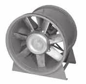
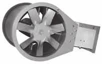
2 AXIAD II The axial flow fan with: High efficiency Low sound level Adjustable pitch blades Complete range of accessories Axial flow or centrifugal fan? Efficiency, sound level and adaptability are factors which must often be weighed against space requirements and investment, installation and service costs when choosing the type of fan for a particular application. The AXIAD II simplifies the choice. AXIAD II has an efficiency of up to 85%. When downstream guide vanes are used, the maximum efficiency of the AXIAD II is very high, even higher than that of belt driven centrifugal fans. Centrifugal Fan Type FC Impeller Type BI Impeller Axial Flow Fan Without With AXIAD II costs less to buy. The AXIAD II is less expensive than a conventional belt driven centrifugal fan. Usually it costs no more than an ordinary axial flow fan. Cost Fan Efficiency Belt Drive Net 65% 80% 75% 85% AXIAD II is simple and inexpensive to silence. Axial flow fans are usually noisier db than centrifugal fans, but on the AXIAD II the difference is no more than a few decibels. In addition, the sound has a higher frequency and has no single tones. So the cost of silencing is usually as low as that for a centrifugal fan. AXIAD II is compact. The AXIAD II is appreciably more compact than an equivalent centrifugal fan if fitted with a diffuser. AXIAD Diffuser AXIAD II is easy to adapt. The AXIAD II has adjustable pitch blades for adjusting the fan to the required airflow and pressure. Just slacken two screws, turn the blade to the required angle and retighten. Axial Flow Fan Centrifugal Fan Hz Belt Driven Centrifugal Fan Type FC Impeller Type BI Impeller AXIAD II costs less to run. High efficiency and the lack of a belt drive combine to ensure low operating costs. The comparison is made at the best efficiency of each fan. Cost Belt Driven Centrifugal Fan Type FC Type BI Impeller Impeller AXIAD II costs less to service. The AXIAD II is direct driven. It has only two bearings, which do not carry the load of a belt drive. This ensures optimum reliability and thus a minimum of service costs. Axial Flow Fan Conventional With Vanes Less Vanes AXIAD II (+) ( ) Axial Flow Fan Conventional AXIAD II AXIAD II also has: A standard foot mounted motor. High strength cast aluminum blades. A lightweight impeller (low bearing load). A complete range of accessories. Simple vibration isolators. It does not need costly inertia bases or concrete foundations. Cost Belt Driven Fan AXIAD II 2 Aerovent Bulletin FA-300
3 Features Available in 11 sizes from 22" to 55" diameter. Airflows from 2000 to 100,000 CFM Static pressure capabilities to 14" w.g. Aerovent is proud to introduce the AXIAD II fan. This fan is the culmination of a design effort to produce a low noise adjustable pitch axial flow fan with high efficiency, compact size and simple blade adjustment. The AXIAD II fan has been researched both aerodynamically and acoustically in AMCA approved computerized laboratories. The result is a fan that produces low sound power level when compared to other standard axial flow and centrifugal fans. The compact size occupies less space than comparable centrifugal fans and the straight-through airflow design provides installation savings. The blade adjustment mechanism is of simple yet strong design consisting of two bolts and a clamp. To change pitch angle it is necessary merely to loosen the bolts, turn the blade to the proper angle, and retighten the bolts. This provides ease of adjustment and assurance that position will not change. The hub of the fan is index marked for each blade angle. The correct blade position is indicated on the performance curves and corresponds to the hub markings. The adjustable pitch blade feature permits easy system balancing or adjustment for unpredictable duct losses. It also permits changing fan characteristics to match changing job conditions. Since the blades can be changed in pitch approximately 35, a wide variation in performance is possible. Compared with airfoil centrifugal or tubular centrifugal fans, AXIAD II fans are much lighter in weight, requiring only simple isolators instead of concrete inertia bases. AXIAD II fans are also more compact, occupying considerably less space than centrifugal fans. The standard AXIAD II fan has an internal direct connected electric drive motor. A variety of full load speeds is possible, giving wide size selection possibilities. The direct connected motor also eliminates cumbersome V-belt drives, and the adjustable pitch blade design eliminates changing pulley sizes to obtain capacity changes. Because the AXIAD II rotor is a high efficiency design, the fan can be supplied with or without the discharge vane section. This feature allows further refinements in fan selection, making economy in first cost and operating expense a certainty. Without Vane With Vane Section Aerovent certifies that the AXIAD II fans shown herein have been tested and rated in accordance with industry accepted test codes, and are guaranteed by the manufacturer to deliver rated performance. Contents Guide to AXIAD II Performance Charts AXIAD II Nomenclature Fan Selection Fan Curve Sizes: Fan Curve Sizes: Sound Data Corrections Guide to Simplified Selection Charts & Tables Annular Velocity Charts Impact Loss and Velocity Pressure Curves Dimensions Aerovent Bulletin FA-300 3
4 Guide to AXIAD II Performance Charts This bulletin presents AXIAD II axial fan performance charts, which show in graphical form volume (CFM), pressure (in. w.g.), efficiency, blade position, and fan brake horsepower (BHP) relationships encountered in the most common AXIAD II fan, rotor and blade combinations operating at motor speeds associated with 60 Hertz operation (900, 1200, 1800, and 3600 RPM). Data on other sizes of fans and fans operating at different speeds is available from the factory. A typical AXIAD II performance chart is represented above. You will notice that the charts are presented on the basis of total pressure. The pressure shown as total pressure is the sum of static pressure, velocity pressure, and impact pressure loss. Static pressure is generally given, while velocity pressure and impact pressure loss are calculable by methods explained elsewhere in this brochure, and at greater length in other Aerovent publications. The operating point of a fan can be determined by knowing any two of the six parameters plotted in the fan charts. Generally, selections are made by establishing total pressure and reading across the total pressure line (in. w.g.) to the intersection with the volume (CFM) line; and noting the blade position and efficiency. BHP is established by reading down the volume line to the previously established blade position, locating the brake horsepower by reading horizontally across the chart. In selecting an AXIAD II fan it is best to choose a size that will operate at a point that is in the vicinity of the maximum efficiency oval. An important consideration in fan selection is the relation of the selection point to the stall line. The stall area is located at the upper end of the blade angle lines and must be avoided. Fan operation in this area is unstable, producing vibration, hunting and surging. To ensure avoiding the area, fan selections should use only 90% of the available pressure at the specified flow. Calculation of a system parabola will show that only by allowing this safety margin can an error involving underestimation of static pressure be corrected by the relatively simple method of increasing blade angle. AXIAD II Nomenclature FTFA (+) MOTOR SPEED Fan Size With Vane Section, ( ) = Less Vanes Full Bladed, if 1 = Half Bladed Hub Size will be 3 with 6 or 3 Blades 4 with 8 or 4 Blades 5 with 10 or 5 Blades 4 Aerovent Bulletin FA-300
5 Fan Selection Straight-Through Airflow in Any Direction The data presented in this manual allows the reader to arrive at a fan selection, starting with airflow, pressure, and downstream duct velocity of the system. Generally, for any given set of the above conditions, there are a number of fans that are possible selections. The parameters for separating these selections are generally (1) brake horsepower, (2) acoustics, and (3) first cost. The table below shows nine possible selections to meet the conditions: 40,000 CFM, 2.5 inches static pressure, discharging into a plenum at 500 feet per minute. It may be of value to the reader to use the selection pressure calculations, efficiency calculations, and brake horsepower calculations. The sound data shown here is presented on the fan curve, and this is correctable to octave band readings as shown on pages 42 through 44. The weight that the designer gives to each of the factors involved in selection is something that varies with each individual case. One would note from perusing the data that fans number 1 and 2 are the most compact, fans number 3 and 4 are the least expensive, fans number 5 and 9 are the quietest, and fans number 8 and 9 take up the greatest amount of space and tend to be very expensive. Under normal circumstances we suggest that the designer, after thoroughly investigating the nine possibilities, would tend to narrow them down to fan number 3 versus fan number 5. In this case, the designer must balance a 10% HP savings and 6 db lower noise output of the FTFA with diffuser against a cost differential approximately 40% which favors the FTFA The final selection should be the result of a thorough systematic cost analysis that your Aerovent representative will be happy to assist you with. Example Given: Flow = 40,000 CFM Static Pressure = 2.5" w.g. Discharge Condition: into Plenum, V4 = 500 FPM FAN FAN VANE TOTAL EFFICIENCY OVERALL RELATIVE OUTLET RPM BHP NO. FTFA SECTION PRESSURE PERCENT PWL COST NO CONE NO CONE NO CONE NO YES DIFF YES DIFF YES YES DIFF Aerovent Bulletin FA-300 5

6 Performance Data FTFA Aerovent Bulletin FA-300

7 Performance Data FTFA Aerovent Bulletin FA-300 7
8 Performance Data FTFA Aerovent Bulletin FA-300
9 Performance Data FTFA Aerovent Bulletin FA-300 9
10 Performance Data FTFA Aerovent Bulletin FA-300
11 Performance Data FTFA Aerovent Bulletin FA

12 Performance Data FTFA Aerovent Bulletin FA-300
13 Performance Data FTFA Aerovent Bulletin FA
14 Performance Data FTFA Aerovent Bulletin FA-300
15 Performance Data FTFA Aerovent Bulletin FA
16 Performance Data FTFA Aerovent Bulletin FA-300
17 Performance Data FTFA Aerovent Bulletin FA
18 Performance Data FTFA Aerovent Bulletin FA-300
19 Performance Data FTFA Aerovent Bulletin FA
20 Performance Data FTFA Aerovent Bulletin FA-300
21 Performance Data FTFA Aerovent Bulletin FA
22 Performance Data FTFA Aerovent Bulletin FA-300

23 Performance Data FTFA Aerovent Bulletin FA

24 Performance Data FTFA Aerovent Bulletin FA-300
25 Performance Data FTFA Aerovent Bulletin FA
26 Performance Data FTFA Aerovent Bulletin FA-300
27 Performance Data FTFA Aerovent Bulletin FA
28 Performance Data FTFA Aerovent Bulletin FA-300
29 Performance Data FTFA Aerovent Bulletin FA

30 Performance Data FTFA Aerovent Bulletin FA-300
31 Performance Data FTFA Aerovent Bulletin FA
32 Performance Data FTFA Aerovent Bulletin FA-300
33 Performance Data FTFA Aerovent Bulletin FA
34 Performance Data FTFA Aerovent Bulletin FA-300
35 Performance Data FTFA Aerovent Bulletin FA
36 Performance Data FTFA Aerovent Bulletin FA-300

37 Performance Data FTFA Aerovent Bulletin FA

38 Performance Data FTFA Aerovent Bulletin FA-300
39 Performance Data FTFA Aerovent Bulletin FA

40 Performance Data FTFA Aerovent Bulletin FA-300

41 Performance Data FTFA , Aerovent Bulletin FA

42 Performance Data FTFA Sound Power Correction Factors The Correction Factors shown below are to be added to the total Sound Power found on the appropriate fan curve, (i.e. for RPM, 10,000 CFM, 0.7" total press. Lwt = 86 the correction at 250 Hz is 7. Therefore the corrected PWL at 250 Hz = 79 db. OCTAVE/BAND HERTZ CENTER FREQUENCY FAN RPM 1/63 2/125 3/250 4/500 5/1000 6/2000 7/4000 8/ (+) (+) (+) (+) (+) (+) (+) (+) ( ) (+) (+) ( ) (+) (+) ( ) Aerovent Bulletin FA-300
43 Sound Power Correction Factors FAN RPM OCTAVE/BAND HERTZ CENTER FREQUENCY 1/63 2/125 3/250 4/500 5/1000 6/2000 7/4000 8/ (+) (+) ( ) ( ) (+) (+) ( ) ( ) (+) (+) ( ) ( ) (+) (+) ( ) ( ) (+) ( ) ( ) (+) (+) ( ) ( ) (+) ( ) ( ) (+) (+) ( ) ( ) (+) ( ) ( ) (+) (+) ( ) ( ) (+) ( ) ( ) (+) (+) ( ) ( ) (+) ( ) ( ) (+) (+) ( ) ( ) (+) ( ) ( ) (+) (+) Aerovent Bulletin FA
44 Sound Power Correction Factors FAN RPM OCTAVE/BAND HERTZ CENTER FREQUENCY 1/63 2/125 3/250 4/500 5/1000 6/2000 7/4000 8/ ( ) ( ) (+) ( ) ( ) (+) (+) ( ) ( ) (+) ( ) ( ) (+) (+) ( ) ( ) (+) ( ) ( ) (+) ( ) ( ) (+) ( ) ( ) (+) ( ) ( ) (+) ( ) ( ) (+) ( ) ( ) (+) ( ) ( ) (+) ( ) ( ) (+) ( ) ( ) (+) Aerovent Bulletin FA-300
45 Selection of AXIAD II Axial Flow Fans Using Simplified Selection Charts Vaneaxial fans are usually rated in terms of total pressure (pt), total pressure being the sum of the system static resistance (ps), plus the velocity pressure (pv) in the duct leaving the fan. In the case of AXIAD II fans, the total pressure shown on the individual fan curves is as measured in the annulus of the vane section, so we have to add the impact loss (pi) to ps and pv to arrive at pt. This is done because the impact loss varies to a considerable degree with variations in discharge duct geometry. All of this is discussed in detail in our brochure Vaneaxial Fan Characteristics and Application Fundamentals. That brochure presents a more accurate method for computing these discharge or impact losses, and this method is used at the factory to check selections on orders before they are manufactured. However, a simplified method would be more desirable for the use of consultants and sales representatives, and this bulletin presents such a method. The enclosed data will permit quick selections and performance comparisons between alternate selections. This method will give you the total pressure within 2% of the computed figure arrived at from the formulas in the brochure. Guidelines for Use of Simplified Selection Tables To select an axial flow fan using the simplified selection charts, it is only necessary to know: 1. Airflow (CFM) 2. Static pressure (SP) 3. Approximate duct velocity downstream of the fan With this information you can make an initial selection of fan size and then verify, using the attached charts, that the selection is a good one or that an alternate size should be chosen. If a single fan system is to be selected, it is desirable to pick the operating point at the area of maximum efficiency. Selection in this part of the curve insures economical operation and good sound characteristics. Since job conditions and calculated requirements do not always agree, it is necessary to allow a safety factor in pressure and flow when making the selection so the fan can do more if field conditions so require. For this reason, do not select a fan at more than 90% of the rated pressure shown on the curve at design flow, and do not select a fan at higher than the maximum indicated blade position. If fans are to be selected to operate in parallel, care must be taken so that fans which come on while the system is operating do not pass through the dip in the fan curve, which is the stall region. To prevent this condition, parallel fans should be selected so that the system curve crosses the maximum blade setting line at a point below the level of the dip. This procedure is necessary to avoid the possibility of the last fan to be started having to pass through the dip in the stall envelope above the performance curve. Since this fan must come up to the system operating pressure before it can contribute to system flow, there is a possibility, if the fan is not selected in this manner, that it may go into a stall condition and not perform as expected. How To Select Fans To make a simplified selection, proceed as follows: 1. Using the individual fan performance charts (higher static pressures require higher RPM), make a tentative selection of fan diameter and hub size. Remember that total pressure will typically be 1" to 3" higher than the static pressure. 2. Using Chart 3 and 4, enter at the bottom with CFM, go up vertically to the tentative fan selection, and then read left to determine V1, the air velocity in the annulus of the fan. 3. Determine velocity pressure (pv), and impact loss (pi) from Chart 5 (if you do not intend to use a diffuser) or Chart 6 (if there will be a diffuser). In either case, enter the chart with the duct velocity downstream of the fan, rise to V1 ascertained in Step 2, and read left for pv + pi. If the fan discharges into a plenum, use the velocity in the cross-sectional area of the plenum as duct velocity. If a sound trap is located in the plenum, use the normal face velocity through the trap as duct velocity. Add pv + pi to your static pressure to arrive at pt. P1 can now be used directly on the individual fan curve to confirm that the selection is a good one or that it should be revised. 5. If the selection is to the left of the optimum efficiency, you may have too large of a fan, and should try the next smaller diameter. If the selection is well below the point of optimum efficiency, you may have selected too large of a hub size, or perhaps a fan with fewer blades will prove more efficient. In making alternate selections, retrace Steps 2, 3, and 4 for your new fan size. Aerovent Bulletin FA
46 AIRFLOW (CFM) CHART 3 ANNULAR VELOCITY (FPM) 46 Aerovent Bulletin FA-300
47 AIRFLOW (CFM) CHART 4 ANNULAR VELOCITY (FPM) Aerovent Bulletin FA
48 pv + pi (inches W.G.) FPM Duct Velocity (V3) pv + pi for FTFA Axial Fans WITHOUT DIFFUSER OR CONE 48 Aerovent Bulletin FA-300
49 pv + pi (inches W.G.) FPM x 100 Duct Velocity (V4 or V5) pv + pi for FTFA Axial Fans WITHOUT DIFFUSER OR CONE Aerovent Bulletin FA
50 Dimensional Data C-D Diffuser and Cone Annular Fan Casing Diffuser AA AA Size LC CL Cone Outlet Area Sq. Ft. EE FF R S T Overall Diff. Cone Inlet Outlet Area ID Area Hub: DD = For Size < 125 BB = AA + 1.5" BB (1) = AA (1) + 1.5" 4 Hub: DD = For Size > 125 BB = AA + 2.0" BB (1) = AA (1) + 2.0" 5 Hub: DD = C-D Diffuser Cone 50 Aerovent Bulletin FA-300
51 Dimensional Data Adjustable Pitch Vaneaxial Fan Fan Size All dimensions in inches A B C D E F G H J L N S T U X Aerovent Bulletin FA


")


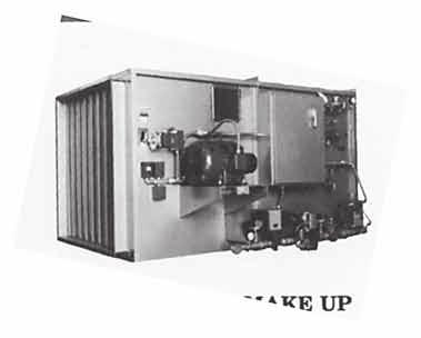
52 Quality Air Handling Equipment AIR HEATER ROOF VENTILATOR CENTRIFUGAL VANEAXIAL AXIAL FLOW Tubeaxial Type VT Industrial Exhaust Upblast Propeller Panel Fan Type W Adjustable Pitch CB / CBA Upblast Axial Mancooler Type VTF Fiberglass Series 14 High Pressure Tu-WAY Ring Fan Type B Higher Pressure Centaxial Fiberglass Tubeaxial Adjustable Pitch Axico Anti-Stall Pressure Blower PRV Centrifugal Gas-Fired Air Make-Up Steam Air Make-Up Door Air Heater WARRANTY Aerovent equipment is guaranteed to deliver its rated output, if properly installed and operated under normal conditions. Aerovent will correct by repair, replacement, or issuance of credit at our option, F.O.B. our plant, defects in material or workmanship which may develop under normal and proper use within eighteen (18) months after date of shipment from our factory, if purchaser gives us notice within ten (10) days of discovering such defects. The correction of these defects by repair, replacement, or issuance of credit shall constitute fulfillment of all obligation to purchaser. (NOTE: We will not assume expense or liability for repairs made outside our factory without prior written consent.) 3MPP08/06 TM
Turbo Blowers. Combustion Excellence Since Features. Benefits
 Turbo Blowers Features Integral molded scroll design Turbine bladed impeller Steel inlet guard Precisely balanced impellers eliminate vibration Complete line of available accessories for adapting to any
Good News From the Doctor
 Good News From the Doctor Understanding Temperature and Altitude Corrections The most common influences on air density are the effects of temperature other than 70 F and barometric pressures other than
Quick Reference Technical Data
 Bulletin 127C 2 Quick Reference Technical Data For over 100 years, The Spencer Turbine Company has specialized in innovative solutions to air and gas handling problems. Spencer's product line includes
HCD HIGH CAPACITY DRUM LOUVER
 HIGH CAPACITY DRUM LOUVER The s (HCD) consist of extruded aluminum blades mounted inside a rotatable drum to produce long air throws with a high degree of directional control. Rotateable drum provides
Centriflow Plus High-pressure plug fan - Technical Data
 Centriflow Plus 3 High-pressure plug fan - Technical Data Contents General description...3 General survey chart...4 Design description Fan Impeller...5 Fan Inlet...5 base with base frame...5 Hub...5 Air
Applied Fluid Mechanics
 Applied Fluid Mechanics 1. The Nature of Fluid and the Study of Fluid Mechanics 2. Viscosity of Fluid 3. Pressure Measurement 4. Forces Due to Static Fluid 5. Buoyancy and Stability 6. Flow of Fluid and
AIRMOUNT VIBRATION ISOLATION
 MOUNT VIBRATION ISOLATION SELECTION AND ISOLATION FORMULA Refer to the selection guide on page 33 for Airmount load and isolation capabilities. Follow this procedure: 1. LOAD CAPACITY Select one or two
Wind Energy Technology. What works & what doesn t
 Wind Energy Technology What works & what doesn t Orientation Turbines can be categorized into two overarching classes based on the orientation of the rotor Vertical Axis Horizontal Axis Vertical Axis Turbines
Compressors. Basic Classification and design overview
 Compressors Basic Classification and design overview What are compressors? Compressors are mechanical devices that compresses gases. It is widely used in industries and has various applications How they
FLOW CONSIDERATIONS IN INDUSTRIAL SILENCER DESIGN
 FLOW CONSIDERATIONS IN INDUSTRIAL SILENCER DESIGN George Feng, Kinetics Noise Control, Inc., 3570 Nashua Drive, Mississauga, Ontario Vadim Akishin, Kinetics Noise Control, Inc., 3570 Nashua Drive, Mississauga,
AC : A LABORATORY EXERCISE TO DEMONSTRATE HOW TO EXPERIMENTALLY DETERMINE THE OPERATING POINT FOR A FAN
 AC 2007-206: A LABORATORY EXERCISE TO DEMONSTRATE HOW TO EXPERIMENTALLY DETERMINE THE OPERATING POINT FOR A FAN Robert Edwards, Pennsylvania State University-Erie Robert Edwards is currently a Lecturer
SUMMARY STEPS TO CERTIFY ACOUSTIC DUCT SILENCER PERFORMANCE UNDER AMCA INTERNATIONAL S CERTIFIED RATINGS PROGRAM
 AMCA International Member Logo cannot be used in catalogs containing performance data. AMCA International Corporate Identity Logo can only be used by AMCA International, Inc. SUMMARY STEPS TO CERTIFY ACOUSTIC
CALMO
 ---------------------------------------------------- Sound attenuator with recessed connection for rectangular ducts ---------------------------------------------------------------------- GENERAL is, due
AF100. Subsonic Wind Tunnel AERODYNAMICS. Open-circuit subsonic wind tunnel for a wide range of investigations into aerodynamics
 Open-circuit subsonic wind tunnel for a wide range of investigations into aerodynamics Page 1 of 4 Works with Computer, chair and work table shown for photographic purposes only (not included) Screenshot
Understanding Lobe Blowers Roots Blowers. Article written by Technical Team of EVEREST GROUP
 Understanding Lobe Blowers Roots Blowers Article written by Technical Team of EVEREST GROUP ompressors and Fans are essentially pumps for gases. Although they differ in construction from liquid handling
Stall & Parallel Operation. Witt&Sohn AG Oct-14
 Stall & Parallel Operation CONTENT Stall & Parallel Operation 1. Definition of Stall 2. Requirements for Parallel Operation 3. Operation of Parallel Fans 4. Stall-free Fans & VSD 2 Definition of Stall,
An Impeller Blade Analysis of Centrifugal Gas Compressor Using CFD
 An Impeller Blade Analysis of Centrifugal Gas Compressor Using CFD Vivek V. Kulkarni Department of Mechanical Engineering KLS Gogte Institute of Technology, Belagavi, Karnataka Dr. Anil T.R. Department
FXT. FXT Cooling Tower RIGGING & ASSEMBLY INSTRUCTIONS
 FXT FXT Cooling Tower RIGGING & ASSEMBLY INSTRUCTIONS FXT Cooling Towers should be rigged and assembled as outlined in this bulletin. These procedures should be thoroughly reviewed prior to the actual
INDUSTRIAL PROCESS AND COMMERCIAL VENTILATION SYSTEMS. Twin City Fan CAST IRON BLOWERS MODEL CIW CATALOG 850 MAY 2012
 Twin City Fan INUSTRIL PROCESS N COERCIL VENTILTION SYSTES CST IRON BLOWERS OEL CIW CTLOG 850 Y 2012 CST IRON PRESSURE BLOWERS odel CIW Twin City Fan & Blower s CIW Cast Iron Pressure Blowers are the perfect
Cover Page for Lab Report Group Portion. Pump Performance
 Cover Page for Lab Report Group Portion Pump Performance Prepared by Professor J. M. Cimbala, Penn State University Latest revision: 02 March 2012 Name 1: Name 2: Name 3: [Name 4: ] Date: Section number:
THEORETICAL EVALUATION OF FLOW THROUGH CENTRIFUGAL COMPRESSOR STAGE
 THEORETICAL EVALUATION OF FLOW THROUGH CENTRIFUGAL COMPRESSOR STAGE S.Ramamurthy 1, R.Rajendran 1, R. S. Dileep Kumar 2 1 Scientist, Propulsion Division, National Aerospace Laboratories, Bangalore-560017,ramamurthy_srm@yahoo.com
6. EXPERIMENTAL METHOD. A primary result of the current research effort is the design of an experimental
 6. EXPERIMENTAL METHOD 6.1 Introduction A primary result of the current research effort is the design of an experimental setup that can simulate the interaction of a windmill with a vortex wake and record
APPLYING VARIABLE SPEED PRESSURE LIMITING CONTROL DRIVER FIRE PUMPS. SEC Project No
 APPLYING VARIABLE SPEED PRESSURE LIMITING CONTROL DRIVER FIRE PUMPS SEC Project No. 1803007-000 November 20, 2006 TABLE OF CONTENTS I. ABSTRACT...1 II. INTRODUCTION...1 III. HISTORY...2 IV. VARIABLE SPEED
Fan and air movement essentials
 1 Properties of air For the purposes of this section we will assume that it is air that will be moved by the various types of fans. The air we breathe is made up of a mixture of gasses - nitrogen 78%,
HIGH FLOW PROTECTION FOR VARIABLE SPEED PUMPS
 Proceedings of the First Middle East Turbomachinery Symposium February 13-16, 2011, Doha, Qatar HIGH FLOW PROTECTION FOR VARIABLE SPEED PUMPS Amer A. Al-Dhafiri Rotating Equipment Engineer Nabeel M. Al-Odan
Laboratory Ventilation. Environmental, Health, and Safety
 No.: BCF020.054 Page: 1 of 7 RECORD OF REVISIONS Date Rev # Details of Change 09/13 1 Updated job titles to reflect ICON job descriptions. Added a definition for Approved Ventilation Contractor and included
Low Wind High Yields Series
 Low Wind High Yields Series Wind Turbines USER S MANUAL Introduction Low Wind High Yields Series rotor blades apply the latest advanced thermoplastic engineering and are manufactured by precision injection
2005 CERTIFICATE OF ACCEPTANCE (Part 1 of 3) MECH-1-A
 MECH-1-A") 2005 CERTIFICATE OF ACCEPTANCE (Part 1 of 3) MECH-1-A PROJECT ADDRESS TESTING AUTHORITY TELEPHONE Checked by/date Enforcement Agency Use GENERAL INFORMATION OF BLDG. PERMIT PERMIT # BLDG. CONDITIONED FLOOR
2005 CERTIFICATE OF ACCEPTANCE (Part 1 of 3) MECH-1-A PROJECT ADDRESS TESTING AUTHORITY TELEPHONE Checked by/date Enforcement Agency Use GENERAL INFORMATION OF BLDG. PERMIT PERMIT # BLDG. CONDITIONED FLOOR
MAINLINE MLA14 AIR CONDITIONERS
 FORM NO. AML-220 Supersedes Form No. PTZ-789 MAINLINE AIR CONDITIONERS Efficiencies up to 16 /13 Nominal Sizes 1.5-5 Ton [5.28 TO 17.6 KW] Cooling Capacities 17.3 to 60.5 kbtu [5.7 to 17.7 kw] Manufactured
Subsonic Wind Tunnel 300 mm
 aerodynamics AF1300 An open circuit suction subsonic wind tunnel with a working section of 300 mm by 300 mm and 600 mm long Screenshot of the optional VDAS software Saves time and money compared to full-scale
SECTION TESTING ADJUSTING AND BALANCING FOR HVAC
 SECTION 23 05 93 - TESTING ADJUSTING AND [Note to PSC: Existing System Coordination When connecting to an existing system, it is the PSC s Responsibility to examine existing documents, field verify existing
A COMPARATIVE STUDY OF MIX FLOW PUMP IMPELLER CFD ANALYSIS AND EXPERIMENTAL DATA OF SUBMERSIBLE PUMP
 IMPACT: International Journal of Research in Engineering & Technology (IMPACT: IJRET) ISSN 2321-8843 Vol. 1, Issue 3, Aug 2013, 57-64 Impact Journals A COMPARATIVE STUDY OF MIX FLOW PUMP IMPELLER CFD ANALYSIS
Pressure on Demand. Air Pressure Amplifiers
 Pressure on Demand Air Pressure Amplifiers Introduction Haskel air pressure amplifiers offer the most comprehensive range in the industry combining simple principles of operation with rugged construction
AXIAL FLOW FANS GENERAL INFORMATION
 ELTA IMPELLER RANGE AXIAL INTRODUTION TEST STANDARDS The Elta impeller ranges included in this catalogue have harnessed the latest technology in axial impeller design, resulting in enhanced pressure development,
COMPUTER-AIDED DESIGN AND PERFORMANCE ANALYSIS OF HAWT BLADES
 5 th International Advanced Technologies Symposium (IATS 09), May 13-15, 2009, Karabuk, Turkey COMPUTER-AIDED DESIGN AND PERFORMANCE ANALYSIS OF HAWT BLADES Emrah KULUNK a, * and Nadir YILMAZ b a, * New
CADENZA
 ---------------------------------------------- ---------------------------------------------------------------------- Attenuator with aerodynamically shaped splitters for rectangular ducts GENERAL has
Acoustical Modeling of Reciprocating Compressors With Stepless Valve Unloaders
 Acoustical Modeling of Reciprocating Compressors With Stepless Valve Unloaders Kelly Eberle, P.Eng. Principal Engineer keberle@betamachinery.com Brian C. Howes, M.Sc., P.Eng. Chief Engineer bhowes@betamachinery.com
SINGLE VALVE WITH LOW-FLOW BYPASS
 CONTROL VALVES Pressure Reducing Valve Sizing Guide Sizing pilot operated reducing valves is not a complicated process. It starts with determining requirements and following these guidelines in valve size
Subsonic Wind Tunnel 300 mm
 aerodynamics AF1300 TecQuipment s AF1300 Subsonic Wind Tunnel. See also AF300S starter set that includes AF1300Z Basic Lift and Drag Balance and a set of AF1300J Three Dimensional Drag Models with the
How to Ensure AMCA-Certified Products Get Installed. An AMCA International White Paper. September, 2015
 September, 2015 How to Ensure AMCA-Certified Products Get Installed An AMCA International White Paper AMCA International 30 West University Dr. Arlington Heights, IL 60004 USA www.amca.org This white paper
Control the air. Control your business.
 Serpent ventilation A complete ventilation system for successful tunneling and mining operations, including system design, fan station, ducting and installation 1 Control the air. Control your business.
Moyno ERT Power Sections. Operational Guidelines
 Moyno ERT Power Sections Operational Guidelines Moyno ERT Power Section Operational Guidelines Index 1. Introduction... 3 2. ERT Performance Graph Interpretation... 3 3. Elastomer Compression (Fit) Recommendations...
TOPICS TO BE COVERED
 UNIT-3 WIND POWER TOPICS TO BE COVERED 3.1 Growth of wind power in India 3.2 Types of wind turbines Vertical axis wind turbines (VAWT) and horizontal axis wind turbines (HAWT) 3.3 Types of HAWTs drag and
Purdue e-pubs. Purdue University. Lee G. Tetu Carrier Corporation. Follow this and additional works at:
 Purdue University Purdue e-pubs International Compressor Engineering Conference School of Mechanical Engineering 2004 Improving Centrifugal Compressor Performance By Optimizing Surge Control (Variable
Adjustable swirl diffuser ODZA TECHNICAL DATA
 Adjustable swirl diffuser ODZA TECHNICAL DATA 2 Adjustable swirl diffuser ODZA Adjustable ceiling swirl diffuser ODZA is intended for commercial and industrial buildings with a large room volume and high
Nirvana Variable-Speed Drive, Contact-Cooled Rotary Screw Air Compressors
 Variable-Speed Drive, Contact-Cooled Rotary Screw Air Compressors Exceptional Reliability Introducing - A True Variable-Speed Drive Compressor Now Available in Single- and Two-Stage. By matching a standard
ULTRA HIGH PRESSURE PAINT GRATE CLEANER FCT-JS OPERATION AND MAINTENANCE MANUAL
 ULTRA HIGH PRESSURE PAINT GRATE CLEANER FCT-JS OPERATION AND MAINTENANCE MANUAL 466 S. Skylane Drive DURANGO, COLORADO 81303 970-259-2869 PHONE 970-259-2868 FAX www.stoneagetools.com sales@stoneagetools
AutoDrill s OUTSTANDING FEATURES
 PRODUCTION DRILLING & TAPPING SOLUTIONS Reduce Your Costs and Increase Your Production The Affordable, Powerful, Compact Solution AutoDrill s OUTSTANDING FEATURES Self Feeding with Air or Oil Thrust Capacity
BACK PRESSURE / SUSTAINING
 In many liquid piping systems, it is vital that line pressure is maintained within relatively narrow limits. This is the function of the 108 Pressure Relief / Back Pressure Series of the OCV control valves.
Exercise 4-2. Centrifugal Pumps EXERCISE OBJECTIVE DISCUSSION OUTLINE DISCUSSION. Pumps
 Exercise 4-2 Centrifugal Pumps EXERCISE OBJECTIVE Familiarize yourself with the basics of liquid pumps, specifically with the basics of centrifugal pumps. DISCUSSION OUTLINE The Discussion of this exercise
FMU4X, FMC4X FMU4P, FMC4P
 ENVIRONMENTALLY SOUND REFRIGERANT FMU4X, FMC4X FMU4P, FMC4P Product Specifications HORIZONTAL FAN COILS FMU4P and FMC4P 1 1/2, 2, 2 1/2, and 3 Tons FMU4X and FMC4X 1 1/2, 2 and 2 1/2 Tons ALL MODELS Horizontal
BACK PRESSURE / SUSTAINING
 SPECIFICATIONS DIMENSIONS In many liquid piping systems, it is vital that line pressure is maintained within relatively narrow limits. This is the function of the 108 Pressure Relief / Back Pressure Series
Effect of Inlet Clearance Gap on the Performance of an Industrial Centrifugal Blower with Parallel Wall Volute
 International Journal of Fluid Machinery and Systems DOI: http://dx.doi.org/10.5293/ijfms.2013.6.3.113 Vol. 6, No. 3, July-September 2013 ISSN (Online): 1882-9554 Original Paper (Invited) Effect of Inlet
Pump Selection and Sizing (ENGINEERING DESIGN GUIDELINE)
") Guidelines for Processing Plant Page : 1 of 64 Feb 2007 (ENGINEERING DESIGN GUIDELINE) Author: A L Ling Checked by: Karl Kolmetz TABLE OF CONTENT INTRODUCTION Scope 5 General Design Consideration Type
Guidelines for Processing Plant Page : 1 of 64 Feb 2007 (ENGINEERING DESIGN GUIDELINE) Author: A L Ling Checked by: Karl Kolmetz TABLE OF CONTENT INTRODUCTION Scope 5 General Design Consideration Type
Advanced Test Equipment Rentals ATEC (2832)
") WARRANTY CLAUSE METROSONICS warrants each new cl-304 manufactured and sold to be free from defects in material, workmanship and construction, except for batteries which may be contained therein, and that
WARRANTY CLAUSE METROSONICS warrants each new cl-304 manufactured and sold to be free from defects in material, workmanship and construction, except for batteries which may be contained therein, and that
Gas Furnaces 95AF. Warranty Heat Exchanger - 20 Year Limited Parts - 5 Year Limited. 95% AFUE 44,000 to 110,000 Btuh Input 2 to 5 Tons Add-On Cooling
 PRODUCT SPECIFICATIONS INSTALLATION OPTIONS Available in Upflow/Horizontal and Counterflow models HEAT EXCHANGER Aluminized steel tapered design primary heat exchanger with crimped construction for long
for Pleasant & Healthy Air-Distribution ISO 9001:2000 Linear Slot Diffusers Product Bulletin 133-D
 for Pleasant & Healthy Air-Distribution ISO 9001:2000 Product Bulletin 133-D Linear Slot Diffusers Pleasant.. Serene.. YOU & DASCO... Since 1964 Partners for good health INTRODUCTION Linear slot diffusers
SUMMARY STEPS TO CERTIFY AIRFLOW MEASUREMENT PERFORMANCE UNDER AMCA INTERNATIONAL S CERTIFIED RATINGS PROGRAM
 AMCA International Member Logo cannot be used in catalogs containing performance data. AMCA International Corporate Identity Logo can only be used by AMCA International, Inc. SUMMARY STEPS TO CERTIFY AIRFLOW
DEVELOPING YOUR PREVENTIVE MAINTENANCE PROGRAM
 DEVELOPING YOUR PREVENTIVE MAINTENANCE PROGRAM By Owe Forsberg, Senior Consultant You are the new Reliability Engineer in a plant that currently lacks documented procedures to maintain the plant. You have
Numerical Fluid Analysis of a Variable Geometry Compressor for Use in a Turbocharger
 Special Issue Turbocharging Technologies 15 Research Report Numerical Fluid Analysis of a Variable Geometry Compressor for Use in a Turbocharger Yuji Iwakiri, Hiroshi Uchida Abstract A numerical fluid
ENGINEERING AUSTRALIA PTY. LTD.
 POWERTECH ENGINEERING AUSTRALIA PTY. LTD. 15 Lorikeet Street, Terrigal NSW 2260 AUSTRALIA. ACN 102 392 558 Phone: (61) 02 4384 6000. Fax: (61) 02 4384 6200. ABN 63 102 392 558 Email: powerteche@bigpond.com
Product Data CAPMP, CARMP EVAPORATOR COIL A COIL - CASED MULTIPOISE CAPMP / CARMP CAPMP / CARMP (3619, 4823, 6025)
") CAPMP, CARMP EVAPORATOR COIL A COIL - CASED MULTIPOISE Product Data (3619, 4823, 6025) A06009 A07904 The CAPMP and CARMP evaporator coils incorporate proven standards for reliable system operation and
CAPMP, CARMP EVAPORATOR COIL A COIL - CASED MULTIPOISE Product Data (3619, 4823, 6025) A06009 A07904 The CAPMP and CARMP evaporator coils incorporate proven standards for reliable system operation and
FAN ENGINEERING. Field Testing of Fans FE-900. Introduction. Testing Equipment. Testing Standards. Prior to Testing
 FAN ENGINEERING Information and Recommendations for the Engineer Introduction There are many reasons why a fan test may be performed. AMCA publications cover three categories of tests. 1. General Fan System
The Usage of Propeller Tunnels For Higher Efficiency and Lower Vibration. M. Burak Şamşul
 The Usage of Propeller Tunnels For Higher Efficiency and Lower Vibration M. Burak Şamşul ITU AYOC 2014 - Milper Pervane Teknolojileri Company Profile MILPER is established in 2011 as a Research and Development
Introduction to Pumps
 Introduction to Pumps 1 Introduction to Pumps 1.0 INTRODUCTION There are many different types of pump now available for use in pumped fluid systems. A knowledge of these pump types and their performance
Installation Operation Maintenance
 682 Seal Cooler New generation seal cooler to meet and exceed the seal cooler requirements stated in the 4th Edition of API Standard 682 Installation Operation Maintenance Experience In Motion Description
Evaporator (DX) Freon Applications 1 12 Tons MHF
 Freon Applications 1 12 Tons MHF") Evaporator (DX) Freon Applications 1 12 Tons > > Used For small to medium freon applications The Global Leader In Heat Exchange Technology With seven decades of experience and commitment to total client
Evaporator (DX) Freon Applications 1 12 Tons > > Used For small to medium freon applications The Global Leader In Heat Exchange Technology With seven decades of experience and commitment to total client
Gerald D. Anderson. Education Technical Specialist
 Gerald D. Anderson Education Technical Specialist The factors which influence selection of equipment for a liquid level control loop interact significantly. Analyses of these factors and their interactions
Senior mechanical energy conversion trends
 Senior mechanical energy conversion trends Introduction and Analysis to fan blade profile and CFD Simulation Of An Appropriate Blade Profile for improving energy efficiency HAMED ROSTAMALIZADEH 95742906
Centrifugal Pump Intro
 Pump ED 101 Joe Evans, Ph.D http://www.pumped101.com Centrifugal Pump Intro Part 1 - Elementary Mechanics & Hydraulics What is a Centrifugal Pump? It is a machine that imparts energy to a fluid causing
Understanding Centrifugal Compressor Capacity Controls:
 Understanding Centrifugal Compressor Capacity Controls: Richard Stasyshan, CAGI Technical Consultant and the Centrifugal Compressor Section of the Compressed Air & Gas Institiute (CAGI). CAGI and our centrifugal
Tradition & Technology
 Gaterotor Support Gaterotor Single Screw Compressors Design & Operation Bearing Bearings Main Screw Parallex Slide System The VSM Single Screw Compressor has one main rotor and two gaterotors. All bearings
Energy Utilisation of Wind
 Ing. Pavel Dostál, Ph.D., Ostrava University 1 Energy Utilisation of Wind Choice of locality Energy and wind output Wind-power installations Wind-power installations: types and classification Basic parts
How Inlet Conditions Impact Centrifugal Air Compressors
 How Inlet Conditions Impact Centrifugal Air Compressors Richard Stasyshan, CAGI Technical Consultant and the Centrifugal Compressor Section of the Compressed Air & Gas Institiute (CAGI). Centrifugal technology
Chapter 2 Pump Types and Performance Data
 Chapter 2 Pump Types and Performance Data Abstract Centrifugal pumps are used for transporting liquids by raising a specified volume flow to a specified pressure level. Pump performance at a given rotor
Sizing of extraction ventilation system and air leakage calculations for SR99 tunnel fire scenarios
 Sizing of extraction ventilation system and air leakage calculations for SR99 tunnel fire scenarios Yunlong (Jason) Liu, PhD, PE HNTB Corporation Sean Cassady, FPE HNTB Corporation Abstract Extraction
The routine maintenance and inspection of local exhaust ventilation (LEV)
") The routine maintenance and inspection of local exhaust ventilation (LEV) This document details the standards for inspection and maintenance that should be achieved for all local exhaust ventilation owned
The routine maintenance and inspection of local exhaust ventilation (LEV) This document details the standards for inspection and maintenance that should be achieved for all local exhaust ventilation owned
Gas Turbine Performance Analysis
 Gas Turbine Performance Analysis Gas turbines may seem too complicated or overwhelming at first glance, but for regular field monitoring on a relative basis, it is not all that difficult. A regular check
Fundamentals of Turboexpanders Basic Theory and Design
 Fundamentals of Turboexpanders Basic Theory and Design Edited Date: September 16, 2015 Presented By: Mr. James Simms Simms Machinery International, Inc. 2357 A Street Santa Maria, CA 93455 U.S.A. About
AIR CONDITIONERS. Features. Manufactured for Fujitsu General America, Inc. Fairfield, NJ. FORM NO. AFJ-220 Supersedes Form No.
 FORM NO. AFJ-220 Supersedes Form No. PTZ-789 AIR CONDITIONERS FO*14C SERIES Efficiencies up to 16 S/13 Nominal Sizes 1 1 /2 to 5 Ton [5.28 to 17.6 kw] Cooling Capacities 17.3 to 60.5 kbtu [5.7 to 17.7
Multiple Pressure Booster Systems With Variable Speed Controller Type BL
 Multiple Pressure Booster Systems With Variable Speed Controller Type BL General Characteristics - Single or multistage pumps - Horizontal or vertical mounting - Total head 30m ~ 250m - Material construction:
Typical Piping Layouts for PREMIX Blower Mixer Systems
 PREMIX Blower s Page 3103 Block & Bleed system is frequently required by insurance authorities. Typical Piping Layouts for PREMIX Blower Systems Maxon assumes no responsibility for the use or misuse of
New Technologies applied to the design and optimization of tunnel ventilation systems
 New Technologies applied to the design and optimization of tunnel ventilation systems Ing. Justo Suárez Area Manager - ZITRON Dot. Ing. Massimiliano Bringiotti Managing Director - GEOTUNNEL Ing. Ana Belén
Gas Furnaces 95AF2V. Warranty Heat Exchanger - 20 Year Limited Parts - 5 Year Limited
 PRODUCT SPECIFICATIONS INSTALLATION OPTIONS Available in Upflow/Horizontal and Counterflow models HEAT EXCHANGER Aluminized steel primary heat exchanger with crimped non-welded construction Stainless steel
The Discussion of this exercise covers the following points: Pumps Basic operation of a liquid pump Types of liquid pumps The centrifugal pump.
 Exercise 2-3 Centrifugal Pumps EXERCISE OBJECTIVE In this exercise, you will become familiar with the operation of a centrifugal pump and read its performance chart. You will also observe the effect that
USER MANUAL. JET TST and JET TST S.
 USER MANUAL JET TST and JET TST S www.sisteven.com Types of Jet fans: JET TST UNI: Impulse axial fan single direction JET TST S UNI: Impulse axial fan single direction (short case) JET TST REV: Impulse
Instruction Manual 742 5/1/2009. Eclipse Ratio Regulators ES Series Version 1
 Instruction Manual 742 5/1/2009 Eclipse Ratio Regulators ES Series Version 1 Copyright Copyright 1997 by Eclipse, Inc. All rights reserved worldwide. This publication is protected by federal regulation
-4.~1~ S L 0 T D I F F U S E R S
 \ I R DISTR I BUTION SPECIALIST -4.~~ S L 0 T D I F F U S E R S SLSD RLSD Supply Linear Slot Diffuser with hit & miss damper, and with deflectors. Return Linear Slot Diffuser with hit and miss damper,
Citation Journal of Thermal Science, 18(4),
,") NAOSITE: Nagasaki University's Ac Title Author(s) Noise characteristics of centrifuga diffuser (Noise reduction by means leading tip) Murakami, Tengen; Ishida, Masahiro; Citation Journal of Thermal Science,
NAOSITE: Nagasaki University's Ac Title Author(s) Noise characteristics of centrifuga diffuser (Noise reduction by means leading tip) Murakami, Tengen; Ishida, Masahiro; Citation Journal of Thermal Science,
Farm-scale winnower revised 12/2005c
 Page 1 of 6 Farm-scale winnower revised 12/2005c By Allen Dong, I-Tech, PO Box 413, Veneta, OR 97487 www.efn.org/~itech/ Public domain, no copyright -a gift to humanity This electric winnower removes chaffs
TV-114 TV-114-A Wind Speed Sensor User s Manual
 Relied on Worldwide in the Most Extreme Conditions TV-114 TV-114-A Wind Speed Sensor User s Manual Texas Electronics, Inc. Dallas, TX 75237 Fax.214.631.4218 4230 Shilling Way Tel.214-631-2490 www.texaselectronics.com
Solving ACC Axial Fan Wind Related Problems
 Solving ACC Axial Fan Wind Related Problems Prepared for ACCUG Conference October 16, 2013 Las Vegas, Nevada By Martin J. Cuerdon P.E. 10/16/2013 Advanced Analytical Solutions, LLC 1 Axial Fan Design Attributes
Brooks Flow Controllers for Gas and Liquid Service Model FC 8744, Series FC 8800 and 8900
 Data Sheet Flow Controllers for Gas and Liquid Service Brooks Flow Controllers for Gas and Liquid Service Model FC 8744, Series FC 8800 and 8900 Model FC 8800 Flow Controller Model 1350/55 with FC 8900
Product Data CAPVP, CARVP, CAPVU, CARVU EVAPORATOR COIL A COIL - CASED AND UNCASED UPFLOW, DOWNFLOW DESIGN FEATURES
 CAPVP, CARVP, CAPVU, CARVU EVAPORATOR COIL A COIL - CASED AND UNCASED UPFLOW, DOWNFLOW Product Data CAPVP / CARVP A06001 A06002 CAPVU / CARVU The CAPVP, CARVP, CAPVU, and CARVU evaporator coils incorporate
DOUBLE-DUCTED FAN CROSS-RELATED APPLICATIONS
 DOUBLE-DUCTED FAN CROSS-RELATED APPLICATIONS [0001] This application claims the benefit of U.S. Provisional Application No. 61/311,672 filed on March 8, 2010, which is incorporated herein by reference
Atmospheric Vent Silencers. Industrial & Marine Silencers
 tmospheric Vent Silencers Industrial & Marine Silencers Maximum performance Minimum fuss Industrial and Marine Silencers (IMS) designs and builds products for organisations engaged in power generation,
STALLING BEHAVIOUR OF A CONTRA-ROTATING AXIAL COMPRESSOR STAGE
 STALLING BEHAVIOUR OF A CONTRA-ROTATING AXIAL COMPRESSOR STAGE by YASHPAL JAIN Thesis submitted in fulfilment of the requirements for the degree of DOCTOR OF PHILOSOPHY Department of Mechanical Engineering
7 th International Conference on Wind Turbine Noise Rotterdam 2 nd to 5 th May 2017
 7 th International Conference on Wind Turbine Noise Rotterdam 2 nd to 5 th May 2017 Sound power level measurements 3.0 ir. L.M. Eilders, Peutz bv: l.eilders@peutz.nl ing. E.H.A. de Beer, Peutz bv: e.debeer@peutz.nl
Air Amplifiers & SYSTEMS
 Air Amplifiers & SYSTEMS We Accept VISA, MasterCard and American Express Air Amplifiers Point-of-Use Air Solutions Maximator air amplifiers are designed to boost plant air pressure or increase the supply
Inlet Swirl on Turbocharger Compressor Performance
 Inlet Swirl on Turbocharger Compressor Performance Lei Huang, Ying Liu, Hua Chen* National laboratory of Engine Turbocharging Technology, Tianjin, China *corresponding author: Tel.:+86-22-5870-7069; fax: