i-fit Positioning Products
|
|
|
- Sabina Davidson
- 5 years ago
- Views:
Transcription


1 i-fit Positioning Products OWNERS MANUAL i-fit Positioning Products Stealth s User and Installation Guide for the i-fit Line of Belts, Thoracic Supports, and Foot Positioners
2 Customer Satisfaction 1.0 Stealth Products strives for 100% customer satisfaction. Your complete satisfaction is important. Please contact us with feedback or suggested changes that will help improve the quality and usability of our positioning products. You may reach us at: Stealth Products, LLC 104 John Kelly Drive, Burnet, TX Phone: (512) Toll Free: 1(800) Fax: (512) Toll Free: 1(800) General Read and understand all instructions prior to the use of the product. Failure to adhere to instructions and warnings in this document may result in property damage, injury, or death. Product misuse due to failure of the following instructions will void the warranty. Immediately discontinue use if any function is compromised, parts are missing, loose, or shows signs of excessive wear. Consult with your supplier for repair, adjustment, or replacement. If this document contains information you do not understand, or there are concerns about safety or operation, contact your supplier. * i-fit and Stealth Products are trademarks of Stealth Products, LLC. i
3 Important Information 2.0 Important Information All persons responsible for fitting, adjustment, and daily use of the devices discussed in these instructions must be familiar with and understand all safety aspects of the devices mentioned. In order for our products to be used successfully, you must: Read and understand all instructions and warnings. Maintain our products according to our instructions on care and maintenance. Devices should be installed and adjusted by a trained technician. Supplier Reference Supplier: Telephone: Address: Purchase Date: Model: ii
4 Introduction 3.0 Before you install or begin using Stealth Products i-fit selection of positioning belts, thoracic supports, and foot positioners, it is important that you read and understand the content of these installation and operating instructions. The installation instructions will guide you through the options and possibilities with the product. Instructions are written with the expressed intent of use with standard configurations. They also contain important safety and maintenance information. For further assistance, or more advanced options, please contact your supplier or Stealth Products at (512) or toll free at Always keep the operating instructions in a safe place so they may be referenced as necessary. All information, pictures, illustrations, and specifications are based on the product information that was available at the time of printing. Pictures and illustrations shown in these instructions are representative examples and are not intended to be exact descriptions of the various parts of the product. Ordering Documentation You can download additional copies of this Owner s Manual on the Stealth website: Or search: i-fit Owner s Manual in the search bar at the top of the page. iii
5 Warranty 4.0 Our products are designed, manufactured, and produced to the highest of standards. If any defect in material or workmanship is found, Stealth Products will repair or replace the product at our discretion. Any implied warranty, including the implied warranties of merchantability and fitness for a particular purpose, shall not extend beyond the duration of this warranty. Stealth Products, LLC does not warrant damage due to, but not limited to: Misuse, abuse, or misapplication of products. Modification of product without written approval from Stealth Products, LLC. Any alteration or lack of serial number, where applicable, will automatically void this warranty. Stealth Products, LLC is liable for replacement parts only. Stealth Products, LLC is not liable for any incurred labor costs. No person is authorized to alter, extend, or waive the warranties of Stealth Products, LLC. Stealth Products warrants against failure due to defective materials or workmanship: Covers: 180 days Hardware: 5 years Electronics: 3 years In Case of Product Failure In the event of product failure covered by our warranty, please follow the procedures outlined below: 1. Call Stealth at +1 (512) or toll free Request the Returns Department or obtain an RA from the Returns Department and follow department or documentation instructions. iv
6 Table of Contents Customer Satisfaction... i 2.0 Important Information... ii 3.0 Introduction... iii 4.0 Warranty... iv 5.0 Table of Contents... v 6.0 Warning Labels... ix 6.1 Warning Labels... ix 6.2 Limited Liability... ix 6.3 Testing... ix 7.0 Design & Function Intended Use Features Important Reminders Pelvic Positioning Pelvic Positioning Belts... 6 Pads Point Belts Point Belts Common Presentations... 9 Anterior Pelvic Tilt... 9 Neutral Pelvic Alignment... 9 Posterior Pelvic Tilt Pelvic Obliquity Pelvic Rotation Belt Angle Thoracic Positioning Thoracic Positioning Items Posture Support Classic Contoured/Zipper v
7 Table of Contents H-Harness Back Pack Straps Y-Straps Chest Straps Belt Anchor Velcro Common Presentations Trunk Kyphosis Trunk Lordosis Trunk Scoliosis Trunk Rotation Foot Positioning Foot Positioning Items Foot Positioners Shoe Holders Foot Positioner Ankle Positioner Pad Footplate Fixed Ankle Support Toe Straps Shoe Holders Shoe Holder Pads Common Presentations Knee Extension Unequal Lower Leg Length Ankle Contractures Knee Flexion vi
8 Table of Contents Installation Instructions Pelvic Belt Installation Fastened Tri-End Tri-End and Around Seat Rail Hinged Sliding Double-D Clip Sliding Double-D Clip with Tri-End Posture Supports/H-Harness/Backpack Strap Installation Strap Risers Installing T-Nuts and Bolts Y-Strap Foot Positioner Installation Toe Strap Ankle Strap Buckle Installation Swivel Buckle Side Release Push Button Shoe Holder Strap Installation Female Buckle Installation Male Buckle Installation Before Each Use Before Each Use Safety Checklist Simulation...44 vii
9 Table of Contents First Time Use First Time Use User Testing Conditions of Use Maintenance Care and Maintenance Cleaning viii
10 Warning Labels 6.0 Warning Labels 6.1 Warnings are included for the safety of the user, client, operator and property. Please read and understand what the signal words SAFETY, NOTICE, CAUTION, WARNING and DANGER mean, how they could affect the user, those around the user, and property. DANGER Identifies an imminent situation which (if not avoided) will result in severe injury, death, and property damage. WARNING CAUTION NOTICE Identifies a potential situation which (if not avoided) will result in severe injury, death, and property damage. Identifies a potential situation which (if not avoided) will result in minor to moderate injury, and property damage. Identifies important information not related to injury, but possible property damage. SAFETY Indicates steps or instructions for safe practices, reminders of safe procedures, or important safety equipment that may be necessary. Limited Liability 6.2 Stealth Products, LLC accepts no liability for personal injury or damage to property that may arise from the failure of the user or other persons to follow the recommendations, warnings, and instructions in this manual. Stealth Products does not hold responsibility for final integration of final assembly of product to end user. Stealth Products is not liable for user death or injury. Testing 6.3 Initial setup and driving should be done in an open area free of obstacles until the user is fully capable of driving safely. The i-fit positioning belts, thoracic supports, straps, and foot positioners should always be tested for the proper fit.. Make sure every physical alteration or adjustment is complete. ix
11 Design and Function 7.0 Intended Use 7.1 Stealth s i-fit line of pelvic belts, vests, chest straps and foot positioners are intended to be used as a way to increase trunk stability, aid in properly aligning the pelvis, and provide a more correct clinical posture in a wheelchair through the use of breathable material and structured support. Pelvic Positioning IFPB-(2-Point) A pelvic positioning belt is required to maintain the pelvis in a neutral alignment for optimal posture, stability and pressure distribution. (4-Point) A pelvic positioning belt is required to maintain the pelvis in a neutral alignment for optimal posture, stability, and pressure distribution. Secondary attachment points will maintain the primary pelvic positioning belt angle for optimal control of the position of the pelvis and to prevent the pelvic positioning belt from moving onto soft tissue which could cause injury. Thoracic Positioning IFPS-Provides anterior thoracic support to maintain an upright, seated posture, as well as to provide stability for function. IFCS (Chest Strap)-Provides anterior thoracic support across the chest, prevents forward movement, and extends functional reach. IFYS (Y-Strap)-Provides anterior thoracic support, primarily designed to de-rotate the trunk. Foot Positioners IFFP-Toe and ankle straps, fixed ankle supports and shoe holders with straps are recommended to maintain the feet on the footplates for pressure distribution, postural support, stability to prevent injury, and/or limit lower extremity extension. 1
12 Design and Function 7.0 Features 7.2 Pelvic Positioning- 2-Point and 4-Point styles Single or dual pull tension straps Padded and non-padded, push button and side release options Offset belt anchors for easy adjustment without loosening the anchor bolts Thoracic Positioning- Swivel buckles for self-adjustment (Lower attachments only) Dynamic and structured options Vinyl face option (Dynamic and structured) Classic and contoured styles (Vinyl face) 2-Point and 4-Point styles Offset belt anchors for easy adjustment without loosening the anchor bolts Foot Positioning- Padded Option Easy attachment points Side release and curved buckles Structured and Dynamic Dynamic vs. Structured Structured i-fit products do not have stretch in the material. It is best used for client s with more aggressive tone. This allows for more effective positioning. Dynamic i-fit products allow for stretch. It is best used for client s with less tone because of it s ability to give with the client s movements. The material has enough tension to still bring the client back to their original position. Contoured vs. Classic Classic style offers a large padded surface for the thoracic area. Contoured style has a narrowed section over the sternum that allows a better fit for females, G-tube users, or those requiring a smaller support surface. NOTICE Prior to use, wash according to label. 2
13 Important Reminders 8.0 Before using the i-fit products, keep in mind the following: NOTICE A seat with angle or built-in contours may help keep the user from sliding in the seat. WARNING Use the positioning belts and supports only to help support the user s posture. WARNING Check that the user cannot slide down in the seating system. If this occurs, the user may suffer chest compression or suffocate due to pressure from the belts or harness. WARNING The belts, posture support and straps, must be snug, but must not interfere with the clients breathing. WARNING Never use a chest harness without a hip belt. NOTICE When traveling in a motor vehicle, it is recommended for wheelchair users to transfer to a vehicle seat and use the vehicle seat belt system or a child safety seat that complies with federal safety standards. The wheelchair should then be stored and secured in the vehicle. 3
14 Important Reminders 8.0 NOTICE Children less than 48 lbs. must always transfer to an approved child safety seat. NOTICE Pelvic positioning belts, thoracic supports and shoulder straps may be used while in transit, but are not designed or approved to provide restraint or protection during a crash. WARNING These devices do not conform to ANSI/RESNA WC20 or SAEJ224. Do not misuse belts or harnesses. WARNING Never use positioning belts or postural supports as motor vehicle restraints, unless they have been designed, tested, and labeled to do so. WARNING When transporting in a motor vehicle, only use in conjunction with restraints that have been designed for restraint in a motor vehicle and that have been crash tested in accordance with SAE J2249 and/or ANSI/RESNA WC/20. 4

15 Pelvic Positioning 5
16 Pelvic Positioning 9.0 Pelvic positioning has a major effect on all aspects of proper seating and safety. It is placed anterior to the pelvis to maintain a neutral pelvic position, to the degree possible for an individual client. A correctly positioned pelvic support may: Help stabilize the pelvis, which directly affects seated body alignment. Aid in preventing sacral sitting, unsafe and non-functional postures, skin breakdowns, and increased pressure on bony prominences. Increase postural stability, decreasing the effort needed to sit. Facilitate posture. Allowing additional upper extremity movement. Contribute to proper head positioning and neck alignment. Reduce negative postural tendencies that can lead to orthopedic deformities and other secondary medical complications. NOTICE These solutions should be made by a clinician or wheelchair professional. Pelvic Positioning Belts 9.1 Part Number Key Pelvic Belts Prefix 1st Digit 2nd Digit 3rd Digit 4th Digit IFPB 5-Push Button Buckle 6-Side Release Buckle 1-1 webbing webbing 3-2 webbing 1-Single Pull 2-Dual Pull 4-4 Point 0-Non Padded Pads Pads Pads Pads Pads 6-4 1/2 Linear Pads 7-5 1/2 Linear Pads 8-7 1/2 Linear Pads 9-9 1/2 Linear Pads 6
17 Pelvic Positioning 9.0 Pads X indicates pad/belt compatibility. Belt Options IFPB5110 IFPB5210 IFPB5310 IFPB6110 IFPB6210 Pads IFPB101 X X IFPB102 X X IFPB103 X X IFPB104 X X Pad Sizes & Dimensions Pad Size Pad Dimension (A x B) XS 1 3/4 x 4 1/4 S 1 1/4 x 5 1/2 M 2 1/2 x 7 1/2 L 2 3/4 x 9 1/2 XL 2 3/4 x 11 1/2 IFPB105 X X When needing to order pads for the following belts, reference the chart above: Padded single pull belts Padded dual pull belts 4-Point linear style belts 2-Point Belts 2-Point Belts are adequate for most clients. The features and angle of attachment must be determined before mounting. The padding option for the belts helps increase pressure distribution. Provides a more comfortable option and helps prevent any digging into the client. 2-Point Non-Padded Side Release Belt 2-Point Non-Padded Buckle Release Belt 7
18 Pelvic Belts Point Belts 4-Point belts are generally used for more aggressive pelvic positioning needs. The primary belt is attached at the desired angle to maintain the pelvis position. The secondary belt is designed to maintain the angle of the primary belt or to provide more control in two different areas. 4-Point belts cannot be ordered without a pad. 4-Point Linear Style Buckle Release Belt 4-Point V-Style Buckle Release Belt 4-Point V-Style Belt Size Webbing Pad Size XS 1 4 1/2 S 1 5 1/2 M 1 1/2 7 1/2 L 1 1/2 9 1/2 L 2 9 1/2 XL /2 8


19 Pelvic Positioning 9.0 Common Presentations 9.2 The following sections detail common presentations of pelvic alignment, and suggested belt usage. Anterior Pelvic Tilt Suggestion: Depending on the clinical outcome desired, attach the front straps of a 4-Point padded seat belt to the seat or frame at 60 or 90. Attach the rear straps to the seat or frame at 30 to 45. Neutral Pelvic Alignment Suggestion: Depending on the clinical outcome desired, use either a 2 or 4-Point pelvic belt used for stability and safety and to support neutral pelvic alignment. Attach the belt at 45 to 60, pulling downward on the top of the thighs. 9


20 Positioning 9.0 Posterior Pelvic Tilt Suggestion: Depending on the clinical outcome desired, attach the front straps of a 4-Point positioning belt at 50 or more. This may help with sliding forward in the seat. This is extremely important if used in conjunction with an anterior positioning vest. Pelvic Obliquity Suggestion: A 2 or 4-Point padded positioning belt may offer the asymmetrical adjustment necessary to position the pelvis and apply forces to bring it back in contact with the seating system. Increased trunk support may be needed to achieve full benefit. 10


. Belt Angle 9.")
21 Positioning 9.0 Pelvic Rotation Suggestion: Depending on the clinical outcome desired, use a 2 or 4-Point belt to secure the position of the non-rotated hip securely. The rotated side is adjusted and secured into position last (based on the range of flexibility). Belt Angle 9.3 Common reference angle measurements referring to positioning belts angle of pull. 11


22 Pelvic Positioning 9.0 CAUTION Never place a positioning belt or strap that applies force to the waist or abdomen. Correct placement of a 2-Point belt. Approximately 45 2-Point hip belt in position over the upper thigh, pulling downwards and backwards. 4-Point hip belt over the ASIS with main webbing running parallel to seat surface. 12

23 Thoracic Positioning 13
24 Thoracic Positioning 10.0 Thoracic positioning has an impact on aspects of proper posture and safety. Thoracic trunk supports are placed in front of the trunk and are designed to maintain trunk alignment with the back of the seating system. A properly positioned trunk allows for: Improved respiratory capacity. A good visual field. Proper head positioning and neck alignment. Improved overall pressure distribution. Reduction of negative postural tendencies that can lead to orthopedic deformities and secondary medical complications. Balance between support and function. SAFETY All adjustments should be made by a trained, certified technician or someone who has been properly trained to work with these products. Thoracic Positioning Items 10.1 Included in the Thoracic Positioning category: Posture Supports - Vinyl Face Support option Back Pack Straps H-Harness Zipper Style Chest Straps Part Number Key Posture Supports Prefix 1st Digit 2nd Digit 3rd Digit 4th Digit IFPS i-fit Posture Support IFBP-i-Fit Back Pack Straps IFHH-i-Fit H-Harness 1-Classic Style 2-Contour Style 3-Zipper Front 4-Back Pack Straps 5-Center Release 1-Dynamic Function 2-Structured Function 3-Vinyl Face, Structured 4-Vinyl Face, Dynamic 0-Rear Pull 1-XS 2-Small 3-Medium 4-Large 5-XL 14
25 Thoracic Positioning 10.0 Part Number Key Chest Straps Prefix 1st Digit 2nd Digit 3rd Digit 4th Digit IFCS-i-Fit Chest Strap 4-Chest Strap 1-Dynamic Function 1-1 Piece 2-2 Piece 3-3 Piece 1-XS 2-Small 3-Medium 4-Large Part Number Key Y-Straps Prefix 1st Digit 2nd Digit 3rd Digit 4th Digit IFYS-i-Fit Y-Strap 3-Y Strap 1-Dynamic Function 2-Structured Function 0-Rear Pull 2-Small 3-Medium Posture Support 10.2 Classic The classic style posture support offers a large, padded surface for the thoracic area. Posture supports help maintain trunk stability, proper alignment, and more correct clinical posture. Pad Size Dimensions (A x B x C x D) A XS 7 3/4 x 12 1/2 x 3 1/2 x 3 1/4 S 9 1/4 x 15 3/4 x 4 x 4 M 9 1/2 x 19 x 5 x 5 L 10 x 22 3/4 x 6 x 6 XL 11 1/2 x 25 3/4 x 7 x 7 B C D 15
26 Thoracic Positioning 10.0 Contoured/Zipper A Pad Size Dimensions (A x B x C x D) XS 8 1/4 x 12 x 1 1/2 x 4 S 9 x 15 1/4 x 1 1/2 x 5 M 10 1/2 x 18 3/4 x 1 1/2 x 5 1/2 L 10 1/2 x 22 1/2 x 1 3/4 x 6 1/2 XL 11 x 25 1/2 x 1 3/4 x 7 1/2 B C D The contoured style posture support has a more narrow section over the sternum, making it a popular choice for female clients. Dynamic or Structured material is available. Vinyl Face is available. H-Harness 10.3 Pad Size Dimensions (A x B) XS 1 3/4 x 8 3/4 A S 2 x 12 1/4 M 2 1/2 x 13 3/4 B L 2 3/4 x 16 1/4 The H-Harness has more contact with the upper thoracic area. The straps are less likely to fall off the shoulders. Center release available only. Structured material is only offered, no dynamic material. 16
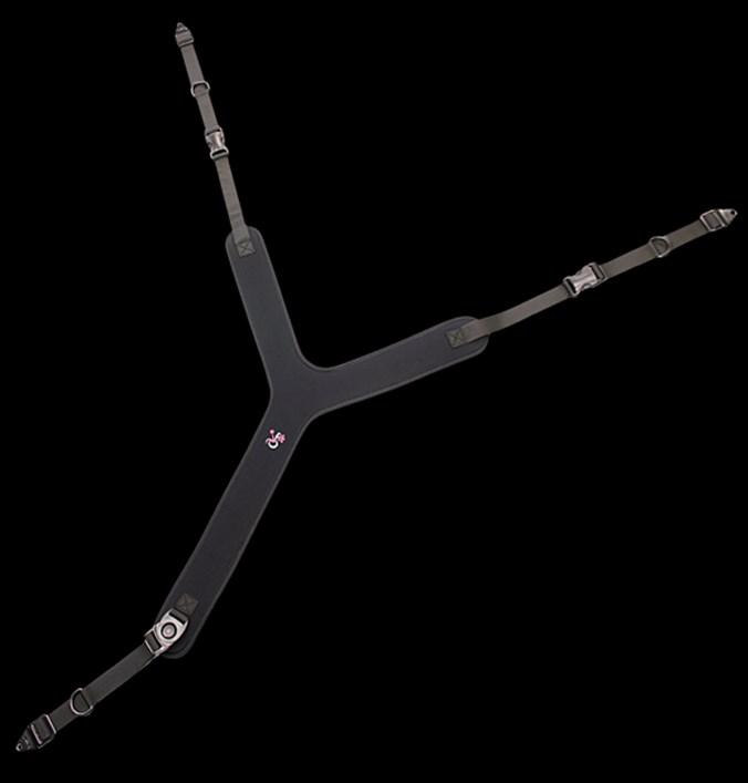
27 Thoracic Positioning 10.0 Back Pack Straps 10.4 Pad Size Dimensions (A x B) XS 1 3/8 x 7 1/2 A S 2 x 9 1/2 M 2 1/4 x 11 1/2 B L 2 1/2 x 13 1/2 Backpack straps have less contact with the client and help with shoulder retraction. Structured material is only available. No dynamic material. Straps can be mounted parallel or crossed over the front of the body. Y-Straps 10.5 Pad Sizes Dimensions (A x B) S 19 x 8 M 22 x 9 1/2 L 25 x 11 1/2 i-fit Y-Straps are typically used to address isolated shoulder rotation. The tension straps retract the rotated shoulder and bring the user in contact with the back support. Dynamic and structured options available. 17
28 Thoracic Positioning 10.0 Chest Straps 10.6 Belt Anchor Style Pad Sizes Dimensions (A x B) XS 7 x 2 S 8 1/2 x 3 M 10 x 4 L 11 1/2 x 5 XL 13 x 6 Belt Anchor Style A Velcro Style Pad Sizes Dimensions (A x B) XS 14 x 2 3/4 S 16 x 2 3/4 M 18 1/2 x 3 1/8 L 21 x 3 1/8 XL 23 x 3 1/4 Velcro Style A B B A i-fit chest straps are another form of anterior thoracic support and will help with providing additional trunk stability and proper alignment. The chest straps protect users with compromised trunk strength from falling forward in their seating environment. Belt Anchor Back mount style with side release buckles on the pad. Velcro 2 piece, Velcro style attachment. Release loop sewn onto pad for attaching and releasing. 18
29 Thoracic Positioning 10.0 Common Presentations 10.7 Trunk Kyphosis Suggestion: A thoracic support such as the H-Harness or Backpack Straps would be helpful to extend the trunk and retract the scapula's. A positioning support would place the trunk over the pelvis, improve breathing, increase safe swallow, head control, maintain a good visual field and improve overall pressure distribution. Trunk Lordosis Suggestion: A thoracic support, contoured or classic, corrects posture and provides pressure to the sternum, aligning the trunk over the pelvis, and reduces shoulder retraction. If the client has more active trunk movement, a dynamic thoracic support will provide more movement while still providing stability. Trunk Scoliosis Suggestion: A Chest Strap, Thoracic Support, or H-Harness will work in combination with trunk and pelvic pads to align the trunk. This permits the head to be level over the trunk and provides a more symmetrical trunk posture. Trunk Rotation Suggestion: A thoracic support such as a Y-Strap or H-Harness would pull the forward shoulder back so the trunk is de-rotated and the user can face forward without neck rotation for vision, swallowing and breathing. 19
30 20 Foot Positioning
31 Foot Positioning 11.0 Foot Positioning has a large effect on aspects of proper seating and safety. Correct foot positioning results in: Increased stability for function. Sustains hip and knee position. Protect feet from injury. Improves foot circulation. Eliminates posterior pelvic tilt. Facilitates self-repositioning in the wheelchair. Foot Positioning Items 11.1 The following are included in the foot positioning category: Foot Positioning - Full Foot Positioners - Ankle Positioners - Fixed Ankle Support Shoe Holders Part Number Key Prefix 1st Digit 2nd Digit 3rd Digit 4th Digit IFFP-i-Fit Foot Positioners IFSH-i-Fit Shoe Holders 0-Component Parts 1-Ankle Positioning System 2-Full Foot Positioning System 3-Ankle Support Fixed Mount 4-Shoe Holder 1-Dynamic 2-Structured 1-3/4 Webbing 2-1 Webbing 0-XS 1-Small 2-Medium 3-Large 4-XL Foot Positioners Foot positioners provide flex and stretch, enabling the individual to benefit from movement within a controlled range and help balance the lower body in response to upper body movements. Shoe Holders Shoe holders provide more lateral foot support because of the pre-built walls along the base plate, giving a rigid support to the foot and thus allowing for stable support. 21
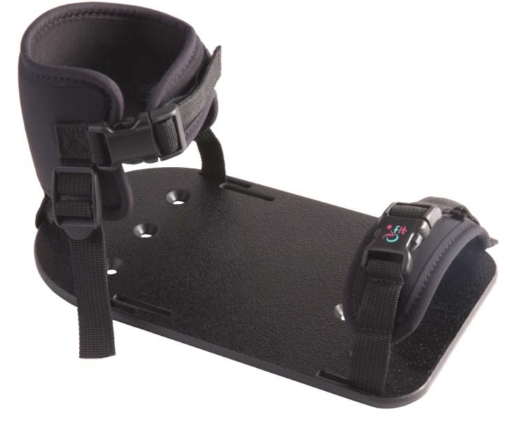
32 Foot Positioning 11.0 Foot Positioner 11.2 Foot Positioner Footplate Size Dimensions (A x B) S XS uses S footplate 7 3/4 x 4 3/4 M 9 1/4 x 5 1/4 L XL uses L footplate 10 1/4 x 5 3/4 The Foot positioner is a foot positioning system that secures the foot in position but still gives movement and consists of a Base Plate, Ankle Positioner Pad, and Toe Strap. These three components can also be ordered separately if a custom configuration is necessary. Pads on the foot positioning system come in dynamic material only. XS & S sizes use 3/4 webbing M, L & XL sizes use 1 webbing Ankle Positioner Pad Ankle Positioner Pad Replacement Pad A-Circumference Ankle Positioner Pad Size Dimensions (A x B) XS 5 1/2-7 x 3 1/2 S 6 1/2-8 x 3 1/2 M 7 1/2-9 x 3 3/4 L 8 1/2-11 1/2 x 4 XL x 4 1/4 IFFP0110 IFFP0111 IFFP0122 IFFP0123 IFFP0124 B The buckle on the pad features a slight curvature to follow the curve of the users ankle, allowing for more comfort. Dynamic material is only available for the ankle positioner pad. 22
33 Foot Positioning 11.0 Footplate Footplate Footplate Size Dimensions (A x B) S 7 3/4 x 4 3/4 XS uses S footplate A M 9 1/4 x 5 1/4 L XL uses L footplate 10 1/4 x 5 3/4 B Slots in the plates are ideal for foot rotation and positioning, and allow space for ankle huggers and toe straps to be added if necessary. Fixed Ankle Support Fixed Ankle Support A-Circumference Pad Size Dimensions A x B XS 5 1/2-7 x 3 1/2 S 6 1/2-8 x 4 B M 7 1/2-9 x 4 L 8 1/2-11 1/2 x 4 XL x 4 1/4 Fixed ankle supports mount to the footplate on a client s chair, and are a comfortable alternative to foot positioners. Supports are made of structured material only. XS & S sizes use 3/4 webbing M, L & XL sizes use 1 webbing 23
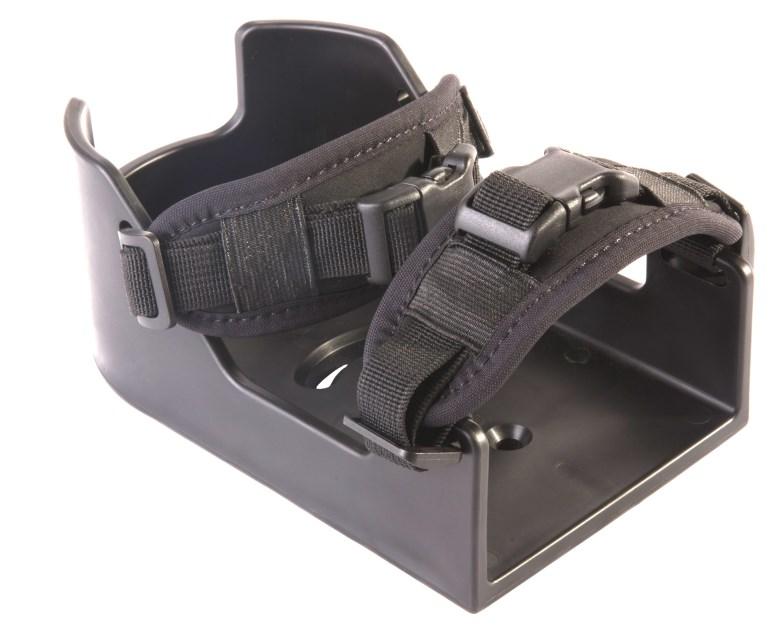
34 Foot Positioning 11.0 Toe Straps Toe Strap Pad Size Size Dimensions (A x B) S 5 1/4 x 2 M 5 3/4 x 2 L 6 1/4 x 2 Replacement Pad IFTS2111 IFTS2122 IFTS2123 Pad A B Toe straps limit aggressive foot rotation and designed for durability. The strap and buckle has a curved design to comfortably rest on the client s foot. Shoe Holders 11.3 Shoe Holders Size Dimensions (A x B x C) S 5 x 3 x 2 M 6 1/4 x 3 1/2 x 2 1/2 L 7 3/4 x 4 1/4 x 3 Tendon Relief Size Dimensions (D x E) S 5 1/4 x 2 M 5 3/4 x 2 L 6 1/4 x 2 Top View C E D A Back View B Shoe holders are a formed footplate that allows for more rigid and lateral support across the foot and is designed for strength and durability. The rear walls offer relief for high tone clients, and all versions are available with the straps pre-attached. 24
35 Foot Positioning 11.0 Shoe Holder Pads Shoe Holder Pads Size Dimensions (A x B) S 5 1/4 x 2 M 5 3/4 x 2 L 6 1/4 x 2 B A The shoe holder pads are made of structured material and is 1/4 thick with a Velcro attachment underneath for easy application. 25
36 Foot Positioning 11.0 Common Presentations 11.4 The following details common presentations of foot positioning and suggested usage: Knee Extension Suggestion: Foot Positioners provide depth adjustability while keeping the foot in place and still allowing movement. Unequal Lower Leg Length Suggestion: Foot Positioners and Fixed Ankle Supports provide greater height adjustability. Adjust the foot and height so the femur is parallel with the seat and the foot is fully supported. The Foot Positioners will reduce pressure under the thighs and increase stability. Ankle Contractures Suggestion: Footplates and Fixed Ankle Supports accommodate fixed posture and support the foot. The Footplate will stabilize the foot, adjusting inversion or eversion, height, and depth without causing joint stress. Knee Flexion Suggestion: Shoe Holder/Foot Positioner can be used to manipulate the feet to be placed to regain stability and relieve stress from the hamstrings and knees, and maintain a neutral pelvic tilt. 26
37 Installation Instructions 27


38 Installation Instructions 12.0 Pelvic Belt Installation 12.1 Pelvic belts may be installed in various manners depending on hardware, seating system, or wheelchair type. Many choices of aftermarket attachment hardware are available. Be sure to read and understand all instructions supplied with any aftermarket hardware. Fastened Tri-End Tri-ends are attached using a fastener and a hole in the seat rail. Tri-End Around Seat Rail Thread the belt around the wheelchair tube in the correct location following the threading instructions below. 28


39 Installation Instructions 12.0 Hinged Sliding Double-D Clip Sliding Double-D Clip with Tri-End CAUTION Ensure that the webbing is routed properly through the belt anchor and does not slip when pulled. Improper routing could cause the strap to become loose and slip from belt anchor. 29
40 Installation Instructions 12.0 The angle that the thoracic supports attach to the seating system or wheelchair frame determines the effectiveness of the product for the user. Posture Support/H-Harness/Backpack Strap Installation 12.2 Solid back should be roughly at shoulder height for anterior support to fit properly. If the strap is attached lower than the shoulders, the strap will pull the shoulders downward. If the shoulder harness is mounted too high, the strap will be less effective in pulling the shoulders back. Shoulder Straps/H-Harness should be positioned so that the vertical straps cross mid-clavicle and the horizontal straps is mid trunk. Backpack Straps should be positioned so the vertical straps cross mid-clavicle. If the back height is lower than shoulder, consider strap risers for correct positioning. It is recommended that the bottom straps be adjusted first, then the top straps to prevent improper alignment. Strap Risers: Strap risers attach to the solid back s t-nuts. Ensure that proper height is provided for comfortable fit on the shoulders. Slide the harness strap through the front of the strap riser and fasten to back. 30
41 Installation Instructions 12.0 Installing T-Nuts and Bolts Fasten tri-ends to the back with the t-nuts and bolts and attach the belt to tri-end. This will allow proper adjustment of the tension straps. CAUTION Check that the belt anchor is properly oriented and mounted flush to the chair. CAUTION Ensure that the bolts and t-nuts have been securely tightened. WARNING The ends of the belt anchor must be securely attached to a mechanically solid mounting point. Severe injury may result if the belt ends become unattached. 31
42 Installation Instructions 12.0 Y-Strap Installation 12.3 One end of the Y-Strap should cross over the shoulder at mid-clavicle and the other cross underneath the axilla on the same side of the body. The other end of the Y-Strap, with a single attachment point, should cross in front of the client s body at an angle and attach on the opposite side, lower than the other two attachment points. Step 1: Position the upper portion of the Y-Strap above and below the rotated shoulder and attach belt anchors to rear face of solid back. Step 2: Stretching the lower strap diagonally across the trunk, attach the lower portion of the Y-Strap to the rear face of the solid back. Step 3: Using the tension straps on the top portion of the Y-Strap, draw the rotated shoulder back until proper position is accomplished
43 Installation Instructions 12.0 Foot Positioner Installation 12.4 Toe Strap Step 1: Thread the toe strap webbing through the front slot of the foot plate. Step 2: Guide the webbing under the foot plate and back up through the slot on the opposite side of the plate. Step 3: Thread the webbing under and through the elastic strap sewn onto the pad, and up through the tri-slide, guiding it through the space closest to the buckle first. Step 4: Slide the webbing over the post, under and through the second gap of the buckle. Pull the strap completely through, ensuring the strap is tight and secure. CAUTION Check that the smooth side of the footplate is facing down prior to installation
44 Installation Instructions 12.0 Ankle Strap Step 1: Thread the strap of the ankle support through the back slot of the foot plate. Step 2: Guide the strap under the foot plate and back up through the slot on the opposite side of the plate. Step 3: Guide the end of the strap up through the tri-slide buckle. Slide the strap through the space closest to the buckle first
45 Installation Instructions 12.0 Step 4: Thread the strap over the post and back under and through the buckle. Pull the strap completely through, ensuring the strap is tight and secure. Step 5: To attach the back strap to the base of the foot plate, guide the webbing through the back slot and pull through. Step 6: Pull the strap up and press the strap against the Velcro strip on the pad. Secure the Velcro and check that is securely fastened
46 Installation Instructions 12.0 Buckle Installation 12.5 Swivel Buckle The swivel buckle is used on the following i-fit products: Positioning Systems Y-Straps Step 1: To release the swivel buckle from the belt, push down on the button in the center of the male swivel buckle. Step 2: Remove the male swivel buckle and attached belt from the female swivel buckle. Make any adjustments necessary. Step 3: To reattach swivel buckle, slide the buckle into the housing. An audible click should occur when the male buckle has been fastened into place, indicating that the belt is secure. If the button does not latch and hold secure, immediately refrain from using the product CAUTION Before engaging the chair, check that all buckles and straps are clear from any mechanical components to prevent damage. 36
47 Installation Instructions 12.0 Side Release The Side Release Buckle is used on the following i-fit products: Pelvic Belts Positioning Systems Chest Straps Back Pack Straps Shoe Holders Foot Positioners Y-Straps Step 1: To remove the side release buckle from the belt, push the prongs of the male buckle in, releasing the buckle from the female housing. Step 2: Remove the male side release buckle and attached belt from the female buckle. Make any adjustments necessary. Step 3: To reattach the side release buckle, slide the buckle into the housing. An audible click should occur when the male buckle has been fastened into place, indicating that the belt is secure. If the buckle does not latch and hold secure, immediately refrain from using the product CAUTION Before engaging the chair, check that all buckles and straps are clear from any mechanical components to prevent damage. 37
48 Installation Instructions 12.0 Push Button The Push Button is used on the following i-fit products: Pelvic Belts Step 1: To remove the push button from the belt, push down on the female buckle with the i-fit logo, releasing the buckle from the female housing. Step 2: Remove the male push button and attached buckle from the female buckle. Make any adjustments necessary. Step 3: To reattach the push button, slide the buckle into the housing. An audible click should occur when the male button has been fastened into place, indicating that the belt is secure. If the button does not latch and hold, immediately refrain from using the product CAUTION Before engaging the chair, check that all buckles and straps are clear from any mechanical components to prevent damage. 38

49 Installation Instructions 12.0 Shoe Holder Strap Installation 12.6 Female Buckle Installation To install the first strap on the foot positioner: Step 1: Start by sliding the strap up through the first slide of the buckle from the bottom. Thread the strap over the first slide and back down through the buckle. Step 2: Place the end of the strap through the precut slot at the top of the foot positioner from the inside going out and pull all the way through

50 Installation Instructions 12.0 Step 3: With the remaining length of the strap, loop back up and lead under the buckle and up in between the two slides. Step 4: Thread the strap over the second slide and down through the buckle. Pull the strap through until it is tight. Adjust the strap to the desired length. 3 4 CAUTION Ensure that the webbing is routed properly through the slider and does not slip when pulled. Improper routing could cause the strap to become loose and slip. 40


51 Installation Instructions 12.0 Male Buckle Installation To install the male buckle and strap onto the foot positioner: Step 1: Turn the buckle down, with the bottom of the buckle facing up. Slide the strap through the first slide, moving right to left. Thread the strap under the post and back up through the second slide. Pull the strap all the way through. Step 2: Pull the strap over the edge with the precut slot and pull over in the direction of the male buckle end. Thread the strap from the bottom onto the buckle and pull through the first slider


52 Installation Instructions 12.0 Step 3: Guide the end of the strap under the first slider. Step 4: Thread the strap over the post and down through the buckle. Pull the strap through until it is tight. Adjust the strap to the desired length. 3 4 Front View 42
53 Before Each Use 13.0 Before Each Use 13.1 Positioning belts, straps and posture supports are NEVER to be used as: Client restraints. On a user who is comatose or agitated. As a motor vehicle restraint without the correct use of approved transit restraint. Safety Checklist 13.2 Check all components for tears, rips, fraying, or physical damage. Check that the receivers for the straps are kept free of debris, dirt, liquids, or foreign objects. Ensure buckles are engaged properly. Engage the ends of the buckles and pull to check for correct engagement. Ensure the belt is snug to the chair and all loose material is away from moving objects. Never use positioning belts or postural supports as motor vehicle restraints, unless they have been designed, tested, and labeled to do so. If any physical damage exists, it is recommended that you replace the complete assembly. If your chair is involved in a vehicular crash, these devices should be replaced. Consult you supplier for these procedures. SAFETY The belts, posture support, and straps must be snug, but must not interfere with the chair. NOTICE Excessive force may cause damage to the product. 43
54 Before Each Use 13.0 Simulation 13.3 As with any sort of positioning intervention, the best way to judge necessary intervention forces and the angles in which they should be applied, is to simulate the forces with your hands. Use your hands to: Mimic the forces and angles applied by a positioning belt. Judge the amount and degree of force needed. Determine how, and at what points, the forces should be applied. Having a partner during the simulation will allow you to use a piece of webbing to help with the simulated angles of pull. NOTICE A seat with angle or built-in contours may help keep the user from sliding in the seat. SAFETY Use positioning belts and harnesses only to help support the user s posture. WARNING Never use an anterior thoracic support without a hip belt and a solid back support. CAUTION Use caution around feeding tubes, wounds, or sensitive areas. 44
55 First Time Use 14.0 First Time Use 14.1 During first time use by the client, it is advised that the dealer or service technician assists and explains the configuration to the customer (the user and/ or the attendant). If needed, the dealer can make final adjustments. User Testing 14.2 It is important that the customer is fully aware of the installation and what can be adjusted in order to gain the best positioning possible: Explain and show the customer how you have executed the installation. Can the user safely operate the wheelchair? Is the placement of the pelvic/thoracic/foot positioner in the optimal position for the user? If needed, adjust the i-fit to the proper position. Explain to the customer possible problems and how to address them. Conditions of Use 14.3 The i-fit positioning belts, posture supports and foot positioners are intended for use as installed by the dealer, in accordance to the installation instructions in this manual. The foreseen conditions of use are communicated by the dealer or service technician to the user and/or attendant during the first time use. If the usage conditions change significantly, please contact your dealer or a qualified service technician to avoid excessive wear and tear or unintended damage. 45
56 Maintenance 15.0 Care and Maintenance 15.1 We recommended that all products be checked for wear and function on a periodic basis and replaced, if necessary, by a wheelchair professional. Repairs should be done with Stealth parts, fasteners, or items appropriate for the service needed. Discontinue use after identifying loose or broken components. Check and retighten all fasteners according to the installation instructions. On a regular basis, check the sticking on the webbing. Cleaning 15.2 Surfaces may be wiped clean with a damp cloth and mild, nonabrasive cleaner. Ensure all cleaners are approved for finished steel, aluminum, plastic and upholstered surfaces. Vests and straps that are removable and DO NOT contain metal components may be machine washed warm (40 ), permanent press, mild process. WARNING Do not bleach. WARNING Do not tumble dry. Dry flat. WARNING Do not iron. 46
57 NOTES
58 NOTES
59 NOTES


60 Stealth Products, LLC. +1(800) (512) John Kelly Drive, Burnet TX P72D09R2 Revision Date
TWB Shoulder Retractors
 Upper Extremities USER MANUAL TWB Shoulder Retractors Stealth s User Manual and Maintenance Guide for The World s Best Shoulder Retractors Customer Satisfaction 1.0 Stealth Products strives for 100% customer
The World s Best Adductors
 Pelvic Support USER MANUAL The World s Best Adductors Stealth s User Manual and Maintenance Guide for The World s Best Adductors Customer Satisfaction 1.0 Stealth Products strives for 100% customer satisfaction.
Upper Extremities USER MANUAL ARMS-ESF3GP. Stealth s User Manual and Maintenance Guide for the 3G Fixed Elbow Stop
 Upper Extremities USER MANUAL ARMS-ESF3GP Stealth s User Manual and Maintenance Guide for the 3G Fixed Elbow Stop Customer Satisfaction 1.0 Stealth Products strives for 100% customer satisfaction. Your
i2i Head & Neck Positioning System
 Positioning & Support USER MANUAL i2i Head & Neck Positioning System Stealth s User Manual and Maintenance Guide for the i2i Head & Neck Positioning System Customer Satisfaction 1.0 Stealth Products strives
TWB Shoulder Retractors
 Upper Extremities USER MANUAL TWB Shoulder Retractors Stealth s User Manual and Maintenance Guide for The World s Best Shoulder Retractors Customer Satisfaction 1.0 Stealth Products strives for 100% customer
Medial Hardware USER MANUAL MTMD-42. Stealth s User Manual and Maintenance Guide for Medial Thigh Support
 Medial Hardware USER MANUAL MTMD-42 Stealth s User Manual and Maintenance Guide for Medial Thigh Support Customer Satisfaction 1.0 Stealth Products strives for 100% customer satisfaction. Your complete
Alternative Drive Mounting Hardware. Quick Install IDCH. I-Drive Control Harness. mo-vis :
 Alternative Drive Mounting Hardware Quick Install IDCH I-Drive Control Harness mo-vis : Customer Satisfaction 1.0 Stealth Commitment 1.1 Stealth Products strives for 100% customer satisfaction. Your complete
HMO500. Headrest Hardware. Stealth s Multi-Axis Headrest Hardware. Installation Manual INSTALLATION INSTRUCTIONS FOR. Stealth Products HMO500 Hardware
 Headrest Hardware Installation Manual HMO500 Stealth s Multi-Axis Headrest Hardware INSTALLATION INSTRUCTIONS FOR Stealth Products HMO500 Hardware Compatible with: All Stealth Products Headrests Customer
P Pod Postural Support System
 P Pod Postural Support System APP-1000XS APP-2000S APP-3000M APP-4000L APP-5000XL www.inspiredbydrive.com WARNING! Read ALL instructions before using this product! IMPORTANT SAFETY RULES Determine, with
Usage and Care Instructions
 SUPERSTAR Student Transportation Add-On Restraint Usage and Care Instructions SUPERSTAR 25-90 lbs. (11.3-40.8 kg) 52 in. (132 cm) tall or less at least 2 years of age *927360* Table Of Contents Store this
STAND AID 1600/ ECONOSTAND
 MAKERS OF STAND AID, POWER TOILET AID AND FREEDOM CHAIR STAND AID 600/ ECONOSTAND INSTRUCTIONS AND WARRANTY FOR STAND AID 600 STAND AID SERIAL # PO BOX 386 Sheldon, IA 50 (800) 83-8580 (7) 34-53 Fax: (7)
Restraint Systems for Infants with Special Needs
 TEST METHOD 213.5 Restraint Systems for Infants with Special Needs Revised: Issued: May 2012R October 1997 (Ce document est aussi disponible en français) Table of Contents 1. Introduction... 1 2. Test
3 Post Pressure Fit System Owner s Manual
 3 Post Pressure Fit System Owner s Manual Use and Care Trouble Shooting Warranty Information Table of Contents 3 Post Pressure Fit System Introduction... 3 Overview of the 3 Post Pressure Fit System...
Harness Range. Harnesses, support pads and straps for positioning and safety Compatible with Non-SOS wheelchairs and seating. Suitable for all ages.
 Harness Range Harnesses, support pads and straps for positioning and safety ompatible with Non-SOS wheelchairs and seating. Suitable for all ages. specialisedorthoticservices.co.uk SOS04 ISS01 0318 Harnesses
USER GUIDE ROLLING WALKERS INSTRUCTIONS FOR USE JANUARY, Maximum User Weight: 170kg (Do not exceed this weight)
") USER GUIDE ROLLING WALKERS INSTRUCTIONS FOR USE JANUARY, 2013 Model Nos: BE07889T Maximum User Weight: 170kg (Do not exceed this weight) Model Nos: BE07890TB Maximum User Weight: 227kg (Do not exceed this
USER GUIDE ROLLING WALKERS INSTRUCTIONS FOR USE JANUARY, 2013 Model Nos: BE07889T Maximum User Weight: 170kg (Do not exceed this weight) Model Nos: BE07890TB Maximum User Weight: 227kg (Do not exceed this
OWNERS MANUAL. Model Shown with optional Primary Mooring Cleats. Portable Mooring System SAFETY OPERATION MAINTENANCE PARTS
 OWNERS MANUAL Model 2400 Shown with optional Primary Mooring Cleats. Portable Mooring System SAFETY OPERATION MAINTENANCE PARTS CAUTION: Before using your new Pier Tender, read rules for Safety, Operation,
SASK-A-POLE OWNERS AND USERS MANUAL
 SASK-A-POLE OWNERS AND USERS MANUAL GENERAL INFORMATION The Saskatchewan Abilities Council s Sask-a-Pole accessibility and transfer aid is designed to help provide safe and easy access to chairs, beds,
Flat Fold Highchair INSTRUCTION MANUAL. Designed and manufactured to BS EN 14988: 2012 IMPORTANT:
 Flat Fold Highchair INSTRUCTION MANUAL Designed and manufactured to BS EN 14988: 2012 IMPORTANT: Thank you for choosing our product. Please read and understand these instructions before using this flat
8MAY15 US RACK, Inc Falcon Drive, Madera, CA
 8MAY15 US RACK, Inc. - 2850 Falcon Drive, Madera, CA 93637-559-661-3050 INSTRUCTIONS for Bedrail-mounted MOTORCYCLE RACK, Model 2001-4TRA WARNING: Do NOT attempt to install or use this rack without following
Installation Manual. Version 12-10
 Installation Manual The products and parts shown herein are to be installed and used adjusted in accordance with these instructions. Any deviation by the buyer, installer, or user from these instructions
Freestander USER MANUAL
 Freestander USER MANUAL The Leckey Freestander has been designed to promote weight bearing and mid line symmetry. This manual shows you how you can quickly and easily make use of all of the functions.
Superstand HLT. Standing System OWNER S MANUAL. ***Note*** Read Owner s Manual before use.
 Superstand HLT Standing System OWNER S MANUAL ***Note*** Read Owner s Manual before use. Manufactured By Prime Engineering A Division of Axiom Industries, Inc. 04-15_SSHLT_OM TABLE OF CONTENTS This owner
SETTING THE HANDLE HEIGHT ON THE ROLLATOR
 Model No: Maximum User Weight: 10910C (Lightweight) 10928C (Heavy duty) 125kg (20st) (Lightweight) 170kg (27st) (Heavy duty) Height of handles: 780-915mm (30.5-36 ) (Lightweight) 790-930mm (31-36.5 ) (Heavy
Study & Manipulative Training Guide
 Study Manipulative Training Guide What is the XCOLLAR? The XCollar is a complete Cervical Spine Splinting System designed especially for EMS. It ensures the highest level of patient safety while significantly
SKYBIRD TRAP OWNER S / OPERATOR S MANUAL PARTS AND ASSEMBLY INSTRUCTIONS
 SKYBIRD TRAP PART NO. 40903 OWNER S / OPERATOR S MANUAL PARTS AND ASSEMBLY INSTRUCTIONS WARNING: THIS MACHINE CAN CAUSE SERIOUS INJURY OR DEATH! THOROUGHLY READ INSTRUCTIONS AND SAFETY INFORMATION BEFORE
Bimini Top, Bimini Top Plus for Jeep Wrangler Vehicles Items # , # and #
 MT_BIMINI_TOPS_INST_LTRR.qxp_Layout 1 8/9/17 3:34 PM Page 1 Installation Instructions Bimini Top, Bimini Top Plus for 2007-2017 Jeep Wrangler Vehicles Items #14100335, #14300335 and #14300435 Bimini Top
Model: 7200 Collegiate Volleyball System
 Model: 7200 Collegiate Volleyball System Installation, Operation and Maintenance Instructions Please read all instructions before attempting installation or operation of these units SAVE THESE INSTRUCTIONS
RADROVER REAR RACK INSTALLATION MANUAL
 RADROVER REAR RACK INSTALLATION MANUAL WWW.RADPOWERBIKES.COM We are here to help! Please contact us at SUPPORT@RADPOWERBIKES.COM or 1-800-939-0310 if you have questions. REV022216 Welcome Thanks you for
Use this key to determine which sections of this Product Manual apply to your job.
 R710 Product Manual Contents Warnings and Important Information 3 Recommended Use 4 Product Information 5 Technical Data 5 Before & During Every Transfer 6 Inspection 6 SoloLift Scale (optional) 6 SoloVest
BROOKFIELD INSTRUCTIONS FOR USE
 06/17 BROOKFIELD INSTRUCTIONS FOR USE Codes 6571 to 6578 CONTENTS PAGE 1.0 INTRODUCTION 1 2.0 ILLUSTRATION & TECHNICAL DATA 2 3.0 FOR YOUR SAFETY 3 4.0 UNPACKING YOUR CHAIR 4 5.0 SETTING UP AND ADJUSTING
JAY J3 Backs We ve Got Your Back
 JAY J3 Backs We ve Got Your Back 2 Superior clinical seating Advantages of Solid Backs 3 Range, Contour and Shapes 4 Spine-Align System 6 Jay Mount Hardware 8 Fitting J3 10 Options and Accessories 12 Ordering
CLASS CYCLE P8000 OWNER'S MANUAL JOHNSON HEALTH TECH. CO., LTD.
 CLASS CYCLE P8000 JOHNSON HEALTH TECH. CO., LTD. No.26, Ching Chuan Rd., Taya Hsiang, Taichung Hsien 428, Taiwan, R.O.C. TEL: +886-4-2566700 FAX: +886-4-2560087 E-mail: sales@johnsonfitness.com http://www.johnsonfitness.com
REDMAN SUIT ASSEMBLING AND PACKING INSTRUCTIONS
 ASSEMBLING AND PACKING INSTRUCTIONS RedMan Training Gear Train realistically and you train to survive. RedMan Training Gear empowers law enforcement, corrections, military and security professionals to
SEATBELT SYSTEMS INSTALLATION MANUAL DRIVEN BY SAFETY
 SEATBELT SYSTEMS INSTALLATION MANUAL DRIVEN BY SAFETY INSTALLATION MANUAL You re ready to use the technology that protects the world s top drivers. Here are the steps to get started. Mounting Restraints
1. Bridge 2. Frontal straps (RFS / LFS) 3. Thick sponge padding 4. Occipital mesh 5. Scaled rubber strap 6. Suspension arm 7. Adaptor A 8.
 3. Thick sponge padding 4. Occipital mesh 5. Scaled rubber strap 6. Suspension arm 7. Adaptor A 8.") 1. Bridge 2. Frontal straps (RFS / LFS) 3. Thick sponge padding 4. Occipital mesh 5. Scaled rubber strap 6. Suspension arm 7. Adaptor A 8. Adaptor B 9. Adaptor C 10. Extender 11. Metallic tube with protector
1. Bridge 2. Frontal straps (RFS / LFS) 3. Thick sponge padding 4. Occipital mesh 5. Scaled rubber strap 6. Suspension arm 7. Adaptor A 8. Adaptor B 9. Adaptor C 10. Extender 11. Metallic tube with protector
BIKE TO GO - USER MANUAL - MODEL#: JBTG24
 BIKE TO GO 24 - USER MANUAL - MODEL#: JBTG24 GET ACQUAINTED WITH YOUR 24 BIKE TO GO Congratulations on your new Jetson 24 folding bicycle! The Jetson 24 Bike to Go is an innovative and fun personal transportation
600 / 600FC OWNER'S MANUAL
 PROGRESSION 600 / 600FC OWNER'S MANUAL Issue 2 / Version E - Dec. 10, 1997 Copyright 1997 GAMMA Sports - All Rights Reserved PROGRESSION 600 / 600FC OWNER'S MANUAL TABLE OF CONTENTS PAGE 1... WARRANTY
BABYSEAT II. Suspension Child Carrier
 BABYSAT II Suspension Child Carrier User's Guide D FR S IT JP KR CHS User needs check whether there are any laws specific to the carrying of children in seats attached to cycles that apply in the country
Pressure Fit System - Two Post Version Owner s Manual
 Pressure Fit System - Two Post Version Owner s Manual Use and Care Trouble Shooting Warranty Information Table of Contents Pressure Fit System Introduction... 3 Overview of the Pressure Fit System... 3
EZ-ON PRODUCT CATALOG. EZ-ON PRODUCTS, LLC 605 Commerce Way West PO Box 660 Jupiter, FL EZ-ON PRODUCTS, LLC
 EZ-ON ADJUSTABLE VESTS SEAT MOUNTS CONVERSION VESTS ACCESSORIES PARTS PRODUCT CATALOG EZ-ON PRODUCTS, LLC 605 Commerce Way West PO Box 660 Jupiter, FL 33458 info@ezonpro.com 1-800-323-6598 EZ-ON Products
Reliance Industries, LLC Operating instructions for the / Bolt-on D-Ring Anchorage. Model # 3071
 Reliance Industries, LLC Operating instructions for the 3071-1 / 3071-2 Bolt-on D-Ring Anchorage Model # 3071 Reliance Industries, LLC PO Box 140008 Denver, CO 80214 Ph. (800) 488-5751 Ph. (303) 424-8650
See JAY Product Comparison Guide notes to the right. Cushions HCPCS Code Page # Lateral Stability Forward Stability. Backs HCPCS Code Page #
 PRODUCT CATALOG PRODUCT RATING See JAY Product Comparison Guide notes to the right. Cushions HCPCS Code Page # Lateral Stability Forward Stability Pressure Management JAY Basic E2601/E2602 5 1 2 3 4 5
Besi Over the Shoulder Harness
 Besi Over the Shoulder Harness Our Over the Shoulder Harness is designed and tested to meet FMVSS-213 standard, along with FMVSS-302 flammability requirements. The Harness must be used with an existing
Worry free unweighted activities Exercise in an upright, controlled and safe position Comfortable, more normal rib and diaphragm interaction
 PneuVest Instructions Includes gait instructions Key Benefits Gait correction Patent 7063678 B1 Worry free unweighted activities Exercise in an upright, controlled and safe position Comfortable, more normal
USER S MANUAL QUESTIONS? CAUTION. Model No. FMEX Serial No. Write the serial number in the space above for reference. Serial Number Decal
 Model No. FMEX81110.0 Serial No. Write the serial number in the space above for reference. USER S MANUAL Serial Number Decal QUESTIONS? If you have questions, or if parts are damaged or missing, please
WORKBOOK/MUSTANG. Featuring: The R82 Next Step Development Plan. mustang. R82 Education
 WORKBOOK/MUSTANG Featuring: The R82 Next Step Development Plan mustang R82 Education CLINICAL WORK BOOK/MUSTANG PAGE 2 PAGE 3 What is Mustang? Mustang is a highly adaptable walking aid for children and
ExtendAire TM II. Intermediate Pressure Accessory Kit USER INSTRUCTIONS
 ExtendAire TM II Intermediate Pressure Accessory Kit USER INSTRUCTIONS THIS MANUAL MUST BE CAREFULLY READ AND FOLLOWED BY ALL PERSONS WHO HAVE OR WILL HAVE THE RESPONSIBILITY FOR USING OR SERVICING THIS
Miller Revolution Key Features
 Thank you for purchasing the Miller Revolution Harness. The Revolution is an all new and totally innovative harness engineered with seven (7) unique components and more than eleven (11) key product features.
 WALKING / K-WALKER 149K Strovolou Avenue, Strovolos, Nicosia, 2048, Cyprus T: +357 22250115, F: +357 22250116, M: +357 70008830 www.abletools.com.cy info@abletools.com.cy B SERIES KAYE POSTURE CONTROL
HEATHFIELD INSTRUCTIONS FOR USE
 01/17 HEATHFIELD INSTRUCTIONS FOR USE Codes 6901-6916 CONTENTS PAGE 1.0 INTRODUCTION 1 2.0 ILLUSTRATION & TECHNICAL DATA 2 3.0 FOR YOUR SAFETY 3 4.0 UNPACKING YOUR CHAIR 4 5.0 SETTING UP AND ADJUSTING
OMS Comfort Harness II
 Assembly of the Shoulder Pads OMS Comfort Harness II Take the larger of the two pieces of webbing (with grommet) and start at the top of the Back Plate: A) Thread the webbing thru the back slanted slots
OPERATION AND INSTRUCTION MANUAL Flat Roof Anchor Model: FRA250L-10X-CTS
 OPERATION AND INSTRUCTION MANUAL Flat Roof Anchor Model: FRA250L-10X-CTS (Patent Pending) WARNING: ALL PERSONS USING THIS EQUIPMENT MUST READ AND UNDERSTAND ALL INSTRUCTIONS. FAILURE TO DO SO MAY RESULT
RACING Models A BOUT THE IMPORTANCE INSTALLATION & OPERATING INSTRUCTIONS THIS MANUAL CONTAINS IMPORTANT OF THIS MANUAL! INFORMATION SHOWN AS
 INSTALLATION & OPERATING INSTRUCTIONS RACING Models THIS MANUAL CONTAINS IMPORTANT INFORMATION SHOWN AS This harness belt, when properly installed and used according to applicable instructions can minimize
Read Instructions carefully before use. Rollator is designed for indoor & outdoor use. Do NOT use as a wheelchair or as a transport chair.
 Charcoal Red Seat Height 500-10191 500-10195 19 500-10211 500-10215 21 500-10241 500-10245 24 User Manual Read Instructions carefully before use. Rollator is designed for indoor & outdoor use. Do NOT use
IMPORTANT: RECEIVING INSTRUCTIONS:
 Instruction Sheet Sidewinder Mechanical Bender IMPORTANT: RECEIVING INSTRUCTIONS: Visually inspect all components for shipping damage. If any shipping damage is found, notify carrier at once.shipping damage
See JAY Product Comparison Guide notes to the right. Cushions HCPCS Code Page # Lateral Stability Forward Stability. Backs HCPCS Code Page #
 CUSHIONS & BACKS PRODUCT RATING See JAY Product Comparison Guide notes to the right. Cushions Page # Lateral Stability Forward Stability Pressure Management JAY Basic E2601/E2602 5 1 2 3 4 5 1 2 3 4 5
Restraint Systems for Disabled Persons
 TEST METHOD 213.3 Restraint Systems for Disabled Persons Revised: Issued : May 2012R June 1, 1987 (Ce document est aussi disponible en français) Table of Contents 1. Introduction... 1 2. Test Devices to
Marine 6-Boat Free-Standing Racks SKU: Updated November 2011
 Marine 6-Boat Free-Standing Racks SKU: 30-061 Updated November 011 Contains: Marine -Boat Free-Standing Racks (SKU 1-003) Marine 3 rd Boat Expansion Racks (SKU 1-0303) Marine Back Legs (SKU -001) 3 Sets
Page 1. Single Scull Car Rack Assembly and User s Manual " "
 Page 1 Single Scull Car Rack Assembly and User s Manual Page 2 Items in the box: (2) V cradles (2) 4 rails (1) 1 3/4 X 18 rail coupler (4) 1/4-20 X 4 1/2 bolts (2) 1/4-20 X 2 1/2 bolts (12) 1/4 flat washers
AIRFRAME HELMET OPERATOR S MANUAL
 AIRFRAME HELMET OPERATOR S MANUAL THIS MANUAL MUST BE CAREFULLY READ BY ALL PERSONS WHO HAVE OR WILL HAVE THE RESPONSIBILITY FOR USING OR MAINTAINING THIS PRODUCT. FAILURE TO USE AND MAINTAIN THE PRODUCT
Rev C /05
 Stair-PRO Stair Chair Operations Manual 6251 6252 EN 6252-009-001 Rev C.0 2018/05 Symbols Operating instructions/consult instructions for use CE mark European authorized representative General warning
7130 Lancer Rear Drive Magnetic Commercial Indoor Cycling Bike
 7130 Lancer Rear Drive Magnetic Commercial Indoor Cycling Bike Owner s Manual Made in Taiwan INDEX IMPORTANT SAFETY INFORMATION... 1 EXPLODED DRAWING... 2 PARTS LIST... 3 ASSEMBLY INSTRUCTION... 4-9 USER
QuadraTop Bimini Top and Bimini Top Plus
 QuadraTop Bimini Top and Bimini Top Plus Installation Manual for 97-06 Jeep TJ Wrangler Vehicles # 11022.XXX5 and # 11022.1XXX BIMINI TOP BIMINI PLUS Loss of vehicle control involves risk of death or serious
Invacare Twilight II Nasal Mask
 Assembly, Installation, and Operating Instructions Invacare Twilight II Nasal Mask LATEX FREE USER: Before using this nasal mask, read this manual and save for future reference. DEALER: This manual must
SOTR Special Operations Tactical Respirator
 SOTR Special Operations Tactical Respirator OPERATOR S MANUAL FOR INDIVIDUAL RESPIRATORY PROTECTION OPS-CORE 2018 OMM G055-1000 REV. B INTRODUCTION ABOUT YOUR SOTR The Ops-Core Special Operations Tactical
Liko SafetyVest, Mod. 93, 94
 Liko SafetyVest, Mod. 93, 94 Instruction Guide English 7EN160146-02 Mod. 93 Mod. 94 Product Description The Liko SafetyVest is a sit-to-stand vest that is unique in terms of safety, form and function.this
walk with independence
 walk with independence Lightweight www.novamedicalproducts.com WARNING Failure to follow any or all safety instructions may result in serious injury or death. adjustment and usage yourself or ambulate
FIRST TEAM SPORTS, INC Storm Portable Series Assembly Instructions
 FIRST TEAM SPORTS, INC Storm Portable Series Assembly Instructions WARNING! WARNING! WARNING! THIS BASKETBALL SYSTEM IS SPRING LOADED AND SHIPPED UNDER TENSION. ATTEMPTING TO ASSEMBLE OR DISASSEMBLE ANY
X-6 STRINGING MACHINE OWNER'S MANUAL. Issue 1 - May Copyright 2004 GAMMA Sports - All Rights Reserved
 X-6 STRINGING MACHINE OWNER'S MANUAL Issue 1 - May 2004 Copyright 2004 GAMMA Sports - All Rights Reserved OWNER'S MANUAL GAMMA X-6 TABLE OF CONTENTS PAGE 1... WARRANTY PAGE 2... FEATURES PAGE 3...ASSEMBLY
310 SERIES TILT-TO-LOAD ROTATOR. The Specialist In Drum Handling Equipment
 OPERATOR S MANUAL FOR MORSE TILT-TO-LOAD DRUM ROTATOR SAFETY INFORMATION: While Morse Manufacturing Co. drum handling equipment is engineered for safety and efficiency, a high degree of responsibility
INSTRUCTIONS FOR USE
 Rebar Chain Assembly INSTRUCTIONS FOR USE 7260XX Rebar Chain Assembly Complies with the current ANSI Z359.1-2007 and all applicable OSHA regulations and requirements. Reliance Industries P.O. Box 2046
OPERATION AND INSTRUCTION MANUAL Beam Trolley Model: BTA012N
 OPERATION AND INSTRUCTION MANUAL Beam Trolley Model: BTA012N WARNING: ALL PERSONS USING THIS EQUIPMENT MUST READ AND UNDERSTAND ALL INSTRUCTIONS. FAILURE TO DO SO MAY RESULT IN SERIOUS INJURY OR DEATH.
01/18 BATH CHAIRS INSTRUCTIONS FOR USE. Code 7607,7609, 7511,7512
 01/18 BATH CHAIRS INSTRUCTIONS FOR USE Code 7607,7609, 7511,7512 SECTIONS PAGE 1.0 BATH CHAIR 1 2.0 BATH CORNER CHAIR 12 Bath Chairs 1 1.BATH CHAIR INSTRUCTIONS FOR USE Code 7607-7609 Bath Chairs 2 CONTENTS
solo harness USER GUIDE
 solo harness USER GUIDE Notices LIMITED WARRANTY For details, refer to the Product Warranty section on the Hollis web site: www.hollisgear.com COPYRIGHT NOTICE This operating manual is copyrighted, all
ATD /8 x 50 Retractable Air Hose Reel Owner s Manual
 ATD-31166 3/8 x 50 Retractable Air Hose Reel Owner s Manual Features Heavy-gauge, all-steel reel assembly 8-position ratchet mechanism locks reel at desired hose length 5-position adjustable roller outlet
InstallatIon and owner s InstrUCtIons
 InstallatIon and owner s InstrUCtIons Wall Mount Series Adjustable and Fixed Height Goal Systems table of Contents Safety Instructions... 2 Goal Specifications... 3 Frame Attachment... 4 Frame Assembly
Assembly Instructions And User Guide
 EZ-1/EZ-CLASSIC QUADRIBENT By Blackbird Designs Inc. Mark 5.2 June 2011 Assembly Instructions And User Guide 1 The Quadribent is 2-seat, side-by-side, human powered vehicle that enables almost anyone to
602 STRINGING MACHINE OWNER'S MANUAL
 PROGRESSION 602 STRINGING MACHINE OWNER'S MANUAL AL Issue 1- April 2000 Copyright 2000 GAMMA Sports - All Rights Reserved PROGRESSION 602 STRINGING MACHINE TABLE OF CONTENTS PAGE 1... WARRANTY PAGE 2...
OPERATION AND INSTRUCTION MANUAL Swivel Anchor Model: SWY100N
 OPERATION AND INSTRUCTION MANUAL Swivel Anchor Model: SWY100N IMPORTANT!!! ALL PERSONS USING THIS EQUIPMENT MUST READ AND UNDERSTAND ALL INSTRUCTIONS. FAILURE TO DO SO MAY RESULT IN SERIOUS INJURY OR DEATH.
MILLER REVOLUTION REVOLUTION KEY FEATURES. Miller Revolution Key Features. Stand Up D-Ring Spring loaded D-Ring simplifi es snaphook connection.
 MILLER REVOLUTION REVOLUTION KEY FEATURES Thank you for purchasing the Miller Revolution Harness. The Revolution is an all new and totally innovative harness engineered with seven (7) unique components
Owner s manual EDGE_Owners_Manual-2011.indd 1 3/1/11 12:36:43 PM
 Owner s manual EDGE_Owners_Manual-2011.indd 1 3/1/11 12:36:43 PM contents 1 Welcome to the Spinning Program 2 Spinning Program Safety 4 Your Spinner Bike 5 Caring for Your Spinner EDGE Bike 6 Bike Assembly
Bike Rack and Tire Carrier
 Bike Rack and Tire Carrier OWNER'S MANUAL Rev: 10.26.2017 Page 1 Bike Rack and Tire Carrier Owners Manual TABLE OF CONTENTS System 2 Description 2 Prior To Operation 3 Manual Slide-Out Bike Rack Operation
U.S. Patent No. 7,922,246. Patents Pending
 U.S. Patent No. 7,922,246 Patents Pending 2 Table of Contents Page General Information... 3 Warnings and Cautions... 4 Tools... 6 SmartDock Parts... 6 Initial Set-Up and Adjustment... 7 Select Valve Retaining
Adapter Kit 5WAR RA NT Y. For use with EZ-Up Gravity Boots and select Teeter Inversion Tables* NEW! Assembly Instructions FULL YEAR
 NEW! Follow along with your smartphone to make assembly even easier! Adapter Kit For use with EZ-Up Gravity Boots and select Teeter Inversion Tables* Assembly Instructions FULL YEAR 5WAR RA NT Y Specifications
S&S. Installation Instructions: S&S Stealth Air Cleaner Kit for Harley-Davidison Models With Stock Cable Operated Delphi EFI
 Instruction 510-0388 01-11-16 Version 1 Copyright 2016 by S&S Cycle, Inc. All rights reserved. Printed in the U.S.A. S&S Cycle, Inc. 14025 Cty Hwy G PO Box 215 Viola, Wisconsin 54664 Phone: 608-627-1497
INSTRUCTIONS FOR USE
 INSTRUCTIONS FOR USE 7100 Series Lanyards Complies with the current ANSI Z359.1-2007 and all applicable OSHA regulations and requirements. Reliance Industries P.O. Box 2046 Deer Park, TX 77536 Phone :
Before you start! Is iwalk 2.0 right for you?
 Before you start! Is iwalk 2.0 right for you? Physical Abilities Requirements 1. Stair Test Before your injury, could you easily walk up and down stairs at normal speed, without using the hand rail? 2.
Model: 5100 OmniSteel Volleyball System
 Model: 5100 OmniSteel Volleyball System Installation, Operation and Maintenance Instructions Please read all instructions before attempting installation or operation of these units SAVE THESE INSTRUCTIONS
SIDE 16 Sidemount System User Manual
 SIDE 16 Sidemount System User Manual Version 1.1, April 15, 2014 Disclaimer This document is proprietary to Scubatech Sp. z o. o. ("Scubatech") and no ownership rights are hereby transferred. No part of
Portable Massage Table User Manual
 Portable Massage Table User Manual For Use With The Model Numbers Below: IT-C62T-H1TS, RK-IO6F-YA6L, SC-1001, SC-1004, SC-1005-MF, SC-1006-MF, SC-401, SC-402, SC-500, SC- 501, SC-501A, SC-501A-MF, SC-601,
LPI Double-T Universal Harness
 LPI Double-T Universal Harness WARNING! YOU MUST FULLY READ, UNDERSTAND AND FOLLOW THESE WARNINGS AND INSTRUCTIONS (WRITTEN AND VIDEO) BEFORE USING YOUR LPI DOUBLE-T UNIVERSAL HARNESS. FAILURE TO FOLLOW
USER S MANUAL. Get out of the
 USER S MANUAL Get out of the Disclaimer This manual contains general instructions for the use, operation, and care of this product. The instructions are not all-inclusive. Safe and proper use of this product
DRAG HARROW SAFETY & OPERATING INSTRUCTIONS. Original Language. Serial No. Order No.
 DR ` DRAG HARROW SAFETY & OPERATING INSTRUCTIONS Serial No. Order No. Original Language DR Power Equipment Toll-free phone: 1-800-DR-OWNER (376-9637) Fax: 1-802-877-1213 Website: www.drpower.com Read and
spinner sport owners manual
 spinner SPORT owners manual contents 1 Welcome to the Spinning Program 2 Spinning Program Safety 4 Your Spinner Bike 5 Caring for Your Spinner Sport Bike 6 Bike Assembly 8 Testing the Bike 9 Troubleshooting
CareFlex FLEXIBILITY IN A WORLD OF MIXED ABILITY
 12 UI HydroTilt accessories. iss3 01/10 UI HydroTilt accessories. iss3 01/10 1 Important Safety Information Please take the time to familiarise yourself with all the aspects of the chair and its functions
Dual Release Walkers 6291 Series. 1 General. 1.1 Symbols WARNING
 User Manual DEALER: This manual MUST be given to the user of the product. USER: BEFORE using this product, read this manual and save for future reference. Dual Release Walkers 6291 Series EN User Manual...page
PMI DELTA HARNESS SG51110, SG51111
 PMI DELTA HARNESS SG51110, SG51111 Manufacturer s Instructions PMIROPE.COM T 1-800-282-ROPE PERSONAL GEAR HARNESSES PRODUCT DESCRIPTION The Delta is a lightweight, comfortable harness that provides a
Liko SupportVest, Mod. 91
 Liko SupportVest, Mod. 91 Instruction Guide English 7EN160145-04 Product Description Liko SupportVest is a comfortable sit-to-stand vest that is easy to use and requires relatively little individual adjustment.
Trampoline & Enclosure Assembly Instructions
 Trampoline & Enclosure Assembly Instructions Safe user weight 250 lbs (115 kg) Version 718602 The information in this document is subject to change without notice. Copyright Springfree Trampoline Inc.
Bimini Top, Bimini Top Plus for Jeep Wrangler (TJ) Vehicles Items #141042XX and #143002XX
 Vehicles Items #141042XX and #143002XX") MT_TJ_BIMINI_TOPS_INST_LTR.qxp_Layout 1 5/11/17 11:21 AM Page 1 Installation Instructions Bimini Top, Bimini Top Plus for 1997-2006 Jeep Wrangler (TJ) Vehicles Items #141042XX and #143002XX Bimini Top
MT_TJ_BIMINI_TOPS_INST_LTR.qxp_Layout 1 5/11/17 11:21 AM Page 1 Installation Instructions Bimini Top, Bimini Top Plus for 1997-2006 Jeep Wrangler (TJ) Vehicles Items #141042XX and #143002XX Bimini Top