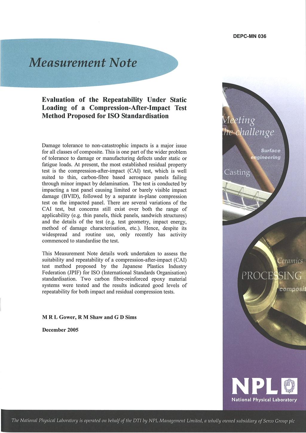
Figure 1 - JPIF proposal for ISO standardisation of the CAI test method
|
|
|
- Ursula Mills
- 5 years ago
- Views:
Transcription
1
2 DEPC-MN 36 INTRODUCTION The use of the compression-after-impact (CAI) test method for laminated fibrereinforced plastic (FRP) materials, particularly where the critical loading mode (compression) is directly linked to the predominant and critical damage type (i.e. delamination), is common within the aerospace industry. Laminated wing skins are typically designed with compression performance as one of the main design drivers. Therefore, compression stress and/or stiffness/strain are key material properties that need to be characterised as they will be significantly affected by the presence of damage within the material. Low velocity impact events such as tool drop or stone impact, often give rise to local delaminations within laminated composite structures. Even though the impact may be transverse to the laminate, damage often propagates along the planes between adjacent layers since these planes do not benefit from the reinforcing effect of the fibres. Growth of the defect will in many cases occur by extension of the delamination into the surrounding material that may not have been directly affected by the initial impact event. The CAI method is typically used to compare residual compression properties to critical design values in order to assess the susceptibility of a material to the growth of such delaminations under quasi-static compressive loading. Despite its widespread and routine use, the standardisation of the method has only just been initiated and several variations exist. A review of CAI test methods was presented in NPL Report CMMT(C)39 [1]. The nonavailability of an agreed standard is due to a lack of industry consensus over the choice of test geometry, impact energy level for the CAI test and method of damage inspection and characterisation. However, different versions of the Boeing derived method has gained greatest acceptance and use. This Measurement Note details work undertaken to assess the suitability and repeatability of a compression-after-impact (CAI) test method proposed by the Japanese Plastics Industry Federation (JPIF) for ISO (International Standards Organisation) standardisation. The proposal is shown schematically in the flow chart of Figure 1 and is favoured by the UK s National Physical SPECIMEN PREPARATION ROUTE 1 ROUTE 2 DEFINED ENERGY LEVEL ( THREAT LEVEL OR 6.67 J/ mm MATERIAL THICKNESS) BVID STUDY AT SEVERAL ENERGY LEVELS (9, 12, 16, 2, 25, 3, 4J) NDE - ULTRASONIC C-SCAN (DENT DEPTH MEASUREMENT) DENT DEPTH MEASUREMENT RESIDUAL COMPRESSION TEST Figure 1 - JPIF proposal for ISO standardisation of the CAI test method 2
3 DEPC-MN 36 Laboratory (NPL). Initially, only Route 1 will be standardised in ISO, to harmonise with the ASTM approach. Route 2 will be standardised at a later date. As with all variations of the CAI test method, the proposed method consists of three phases; (i) the impact resistance test; (ii) inspection and measurement of damage; and (iii) measurement of the residual compression strength. Specific details on the various aspects of the JPIF proposal for the CAI method are give in Table 1. The initial JPIF proposal includes two routes by which the impact resistance and resulting level of damage can be evaluated. For impact resistance, Route 1 allows the user to set a specific impact energy level, which corresponds to the anticipated threat energy level from an event, such as a tool drop during maintenance, or a value of 6.67J per millimetre of material thickness. The resulting damage area should then be determined nondestructively by ultrasonic C-scan as well as measurement of dent depth on the impacted face of the material. Route 2 requires the user to determine the impact energy level required to cause barely visible impact damage (BVID), which is defined as a dent depth of.5 mm. This energy level, E BVID, is determined by performing a series of impact tests over a range of energy levels and measuring the resulting dent depths. By plotting impact energy against dent depth, E BVID can be found by interpolation. Route 2 does not place a requirement on the user to determine damage area using ultrasonic inspection. Route 2 agrees with the Airbus approach [2] and their input into the EN Aerospace version of the test. EVALUATION OF JPIF CAI TEST METHOD PROPOSAL The following sections provide details on the tests undertaken to assess the suitability and repeatability of the JPIF proposed CAI method. It is noted that the wider assessment offered by Route 2 has been followed for determination of the impact energy. Materials Two material systems were tested in this study and were supplied by Hexcel Composites Ltd Table 1 - Details of Recommended CAI Method Variable Proposed detail Route 1 Route 2 Comment Test machine Support Specimen Drop weight tower (instrumented) Steel base plate with 75 mm x 125 mm cut-out 15 x 1 x ~4 mm Provides detail of impact event throughout Clamping Specimen centrally positioned over cut out in base plate and held flat (not clamped) with four toggle clamps. No allowance for lifting of specimen corners Indentor Impact energy 16 mm diameter hemispherical steel Defined energy level e.g. equivalent to perceived threat, 6.67J/mm thickness 9, 12, 16, 2, 25, 3, 4J. BVID energy determined for.5mm dent depth Representative of tool drop or stone impact Inspection Ultrasonic C-scan (plus also measure dent depth) Measure dent depth Investigates relationship between dent depth and delamination area Compression Specimen edges simply supported in compression jig Loaded at.5 mm/min to failure 3
 2s 56.5 and SP Systems Ltd as industry co-funding contributions to the project.")
4 DEPC-MN 36 Table 2 - Details of Materials Used in CAI Tests Material Supplier Generic Description Measured Fibre Volume Fraction V f (%) 1 SP Systems unidirectional carbon fibre-reinforced epoxy 57.2 autoclave cured 2 Hexcel quasi-isotropic lay-up (+45//-45/9) 2s 56.5 and SP Systems Ltd as industry co-funding contributions to the project. Both materials were unidirectional (UD) carbon fibrereinforced epoxy pre-pregs. The material systems used and measured fibre volume fractions are detailed in Table 2. Panel and specimen preparation Test panels were manufactured at NPL according to the fabrication method given in [2] and following material supplier s guidance. All panels were autoclave cured at 125 C for 1 hour (3 C/minute ramp at 7 bar). The lay-up of the panels was quasi-isotropic (+45//-45/9) 2s. Specimens were extracted from test panels in accordance with [4] (additional guidance on machining operations is given in [5]). Machining operations were performed using a Bennett diamond grit coated circular saw, with water used as a coolant/lubricant. Phase 1 - Impact resistance For the impact resistance tests, rectangular specimens (1 x 15 x ~4 mm) were supported on a steel base plate containing a 75 mm x 125 mm cut out (Figure 2). Specimens were centrally placed over the cut out region and four toggle clamps with rubber tips were used to hold the specimens flat against the test jig. The impact support plate was positioned centrally under the aperture of a Rosand IFW5 drop weight impact tower and a series of impact tests were performed over a range of energy levels (9, 12, 16, 2, 25, 3, and 4 Joules). Prior to performing the impact tests the force transducer on the instrumented indentor was calibrated according to a method previously developed at NPL [6] (recommended in ISO [7] and used for UKAS calibrations). The drop mass and height were varied in order to give the correct level of impact energy. Each impact test was performed on a separate specimen and a second strike prevention device was employed to ensure that specimens received only one impact. Impact energy versus dent depth (see Phase 2 for details on how dent depths were measured) plots were used to determine E BVID (energy to cause a dent depth of.5 mm) and a further 5 impact tests were then undertaken at this energy level. Phase 2 - Inspection and measurement of damage After impact and an initial visual inspection, specimens were further inspected to determine the depth of the dent caused by impact and damage area (i.e. delamination). The techniques used for determining dent depth and damage area are described in the following sections. Figure 2 - Schematic of impact support plate for CAI tests Dent depth: A laser profilometer was used to measure dent depths. The set-up is shown in Figure 3. Measurements were made immediately after impact and also 24 hours later to assess the effects of relaxation of the materials. For both materials the impact energy to cause a dent depth of.5 mm was 4

5 DEPC-MN 36 the specimen twice (Figure 4). The specimen is supported above a flat glass reflector plate and the inspection area, transducer and reflector plate are fully immersed in water. A short ultrasonic pulse passes through the specimen, normal to the surface, is reflected by the reflector plate and travels back through the specimen again to the transducer. The reflected signal is captured, amplified and displayed on an oscilloscope and the amplitude is measured and recorded. Figure 3 - Laser profilometer apparatus used for dent depth measurements found by interpolation of plots of measured dent depth versus impact energy. This level of energy is defined as the energy to cause barely visible impact damage (E BVID ). Damage area: A double through-transmission method was used to inspect all specimens and provide a measure of damage area. In this inspection mode, a single transmitter-receiver transducer scans along the material surface capturing signals that have propagated through Figure 4 - Ultrasonic C-scan double through-transmission method (immersion) Using the double-through transmission approach enhances the detection of nearsurface flaws by directly monitoring the amplitude of the back-surface reflection rather than monitoring intermediate signals between the front and back reflections. The presence of a near-surface discontinuity will result in a reflected signal, and thus a reduction in energy of the transmitted pulse that propagates to the reflector and back. This effectively reduces the amplitude of the reflection. The damage area was determined by measuring that area of the specimens which had a level of attenuation 6 db below the average attenuation level of non-impacted material. This level corresponds to a signal loss of ~5%. This method of measuring the damage area is detailed in NPL developed procedures [8]. Phase 3 - Residual Compression Tests Prior to conducting the compression tests, all impacted specimens were strain gauged in order to monitor the degree of bending during compression loading. Pairs of strain gauges were bonded to specimens in locations shown in Figure 5. CAI tests were then undertaken using the test rig shown in Figure 6. The JPIF proposal recommends the use of strain gauges to check the alignment and degree of bending of specimens, but it does not provide a value for the allowable level of bending. Therefore, guidance was taken from BS EN ISO [9], i.e. bending is acceptable if the difference between strains recorded on each face of the specimen throughout the duration of the test is less than or equal to 1%. This criterion is fairly strict especially when one considers that the percentage error in strain readings at low strain levels is higher than at higher strain levels and that immediately prior to failure 5

6 DEPC-MN 36 to failure at a crosshead displacement rate of.5 mm/minute. The CAI strength was calculated from the maximum load divided by the nominal specimen cross sectional area. RESULTS Figure 5 - Position of strain gauges on impacted test panels strain readings often diverge drastically as the material starts to deform. Consequently, the bending criterion was relaxed slightly so that the difference in strain readings was only required to be less than or equal to 1% between 1 and 95% of the compressive failure stress. This modification is being considered for the BS EN ISO compression standard [9]. After careful positioning in the test rig (see Figure 6), vertical alignment was ensured using a spirit level and successful alignment checks of the jig made. Specimens were tested Immediately after impact (t ) the dent depths for all panels were measured with the laser profilometer. Where possible the dent depths were also measured 24 hours later to determine the degree of relaxation of the material. Dent depth profiles are shown in Figure 7 indicating the increasing depth and extent of dent with impact energy. Example dent depth plots obtained using the laser profilometer are shown in Figure 8. In general the dent depth results shown in Tables 3 and 4 indicate that relaxation of both materials does occur, but that the degree of relaxation is quite small (~.2-.3 mm for a 4 J impact). Distance from centre of dent (mm) J 3J 25J 2J 16J 12J 9J 5J Dent depth (mm) (a) Distance from centre of dent (mm) J 3J 25J 2J 16J 12J 9J 5J Dent depth (mm) (b) Figure 6 - CAI test apparatus Figure 7 - Dent depth profiles for (a) material 1 and (b) material 2 6

7 DEPC-MN 36 Figure 8 - Laser profilometer dent depth plots for Material 2 Damage area (mm 2 ) Damage area Dent depth (t) EBVID=~34J Dent depth (mm) Damage area (mm 2 ) Damage area Dent depth (t) EBVID=~3J Dent depth (mm) Impact energy (J) Impact energy (J) (a) (b) Figure 9 - Dent depth and damage area results for; (a) Material 1 and (b) Material 2 Force (kn) 1 2AQUL1 (34J) 2AQUL11 (34J) Deflection (mm) Force (kn) 1 1AQUN11 (3J) 9 1AQUN12 (3J) Deflection (mm) (a) (b) Figure 1 - Force vs. deflection for BVID energy level impacts; (a) Material 1 and (b) Material 2 7
.")
8 DEPC-MN 36 Figure 11 - Damage as determined by ultrasonic C-scan inspection for Material 1 In order to determine E BVID, plots of dent depth (at t ) versus impact energy were constructed (Figure 9) and the energy corresponding to a.5 mm dent depth was found by interpolation (E BVID for Material 1 was ~34 J and ~3J for Material 2). Five further impacts per material were performed at these E BVID energy levels. It is noted that if Route 1 had been followed in order to determine impact energy (i.e. 6.67J per material of material thickness) then the energy level for Material 1 would have been ~32J and for Material 2 ~28J). Examples of forcedeflection impact traces are shown in Figure 1 for both materials. In general, the impact tests showed good levels of repeatability and the coefficient of variation in peak force was less than 6% for both materials. After impact, all panels were ultrasonically C-scanned and the damage areas measured (Figures 11 and 12, Tables 3 and 4). One or two of the C-scan images in Figure 11 show considerable changes in colouration, however this was found to be due to the panels not lying flat on the glass reflector plate rather than due to damage. It was noted that at E BVID, all panels Figure 12 - Damage as determined by ultrasonic C-scan inspection for Material 2 8
9 DEPC-MN 36 Specimen Impact Energy (J) Peak Force (kn) Dent Depth (mm) t t +24hrs Damage Area (mm 2 ) Failure Strain (%) CAI Strength (MPa) 2AQUL AQUL AQUL AQUL AQUL AQUL AQUL AQUL BVID Impact Tests - Impact Energy of 34 J Table 3 - Results for Material 1 2AQUL AQUL AQUL AQUL AQUL Mean Standard deviation (±) Coefficient of variation (%) Specimen Impact Energy (J) Peak Force (kn) Dent Depth (mm) t t +24hrs Damage Area (mm 2 ) Failure Strain (%) CAI Strength (MPa) 1AQUN AQUN AQUN AQUN AQUN AQUN AQUN AQUN BVID Impact Tests - Impact Energy of 3 J Table 4 - Results for Material 2 1AQUN AQUN AQUN AQUN AQUN Mean Standard deviation (±) Coefficient of variation (%)
10 DEPC-MN Damage area Dent depth (t) Damage area Dent depth (t) Damage area (mm 2 ) Dent depth (mm) Damage area (mm 2 ) Dent depth (mm) CAI Strength (MPa) CAI Strength (MPa) (a) (b) Figure 13 - CAI strength against dent depth and damage area results for; (a) Material 1 and (b) Material 2 CAI strength (MPa) Material 1 Material 2 catastrophically under compression loading by growth of delaminations across the width of the panels perpendicular to the loading direction. Failure strength and strain results showed good levels of repeatability - less than 1% for strain and 7.1% for strength Impact Energy (J) Figure 14 - CAI strength versus impact energy CONCLUSIONS AND FURTHER WORK The results of this study have evaluated the suitability and repeatability of the JPIF proposed CAI method. A number of salient conclusions can be drawn from the work undertaken: exhibited considerable back face damage, including ply splitting and delamination, whilst the impacted surfaces of the panels all sustained fracture of the surface ply at the bottom of the dent. The variations in dent depth and damage area indicate a lesser degree of repeatability and this is reflected in the lack of agreement between force-deflection traces after peak force has been reached (Figure 1). In general, whilst damage area and dent depth increased with increasing impact energy, there was no clear trend between dent depth and damage area. The CAI strength and failure strain results are detailed in Tables 3 and 4. The strength results are plotted as a function of dent depth and damage area in Figure 13 and impact energy in Figure 14. All specimens failed The JPIF method provides the user with the option of choosing how to set the impact energy, i.e. Route 1 or 2. The results have shown that levels of E BVID determined by Route 2 were in fairly close agreement with those calculated from setting the impact energy to 6.67J/mm (Route 1). It is considered that the.5 mm dent depth corresponding to a level of barely visible damage is too large as for both materials fracture of the top ply occurred in the bottom of the impact dent. Considerable back face damage was also observed at this energy level. In general, there was no discernible correlation between dent depth and damage area. 1
11 DEPC-MN 36 The impact and residual compression tests showed good levels of repeatability despite a large amount of scatter in dent depths and damage area. Although the repeatability of the JPIF proposed CAI method has been assessed in this work, the reproducibility (i.e. the variation in results obtained between different test sites) needs to be investigated. An international round-robin (to be led by NPL) aimed at generating reproducibility data is planned as part of further work within project F12 - Development of test methods for determining the criticality of defects in composite materials systems under long-term loading. In addition it is emphasised that whilst the CAI is currently used for static testing, in reality damage is more likely to propagate to a large size, or catastrophically, under a long-term cyclic load rather than a one-off static overload. Therefore work is also being undertaken within project F12 to assess the suitability of the CAI test method for fatigue loading. 11
12
Ultrasonic Inspection of In-Service Composite Bicycles and Components
 Ultrasonic Inspection of In-Service Composite Bicycles and Components Cyclitech 6-7 Dec 2016 Raoul Luescher Director Luescher Teknik Pty Ltd Personal Background Diploma of Mech Eng 1989. Level 2 NDI technician
EXPERIMENTAL RESULTS OF GUIDED WAVE TRAVEL TIME TOMOGRAPHY
 18 th World Conference on Non destructive Testing, 16-20 April 2012, Durban, South Africa EXPERIMENTAL RESULTS OF GUIDED WAVE TRAVEL TIME TOMOGRAPHY Arno VOLKER 1 and Hendrik VOS 1 TNO, Stieltjesweg 1,
ASSESSMENT AND ANALYSIS OF PIPELINE BUCKLES
 ASSESSMENT AND ANALYSIS OF PIPELINE BUCKLES GE Oil & Gas PII Pipeline Solutions Inessa Yablonskikh Principal Consultant Aberdeen, November, 14 th 2007 Assessment And Analysis Of Pipeline Buckles Introduction
New Highly Productive Phased Array Ultrasonic Testing Machine for Aluminium Plates for Aircraft Applications
 19 th World Conference on Non-Destructive Testing 2016 New Highly Productive Phased Array Ultrasonic Testing Machine for Aluminium Plates for Aircraft Applications Christoph HENKEL 1, Markus SPERL 1, Walter
Inspection of CANDU Reactor Pressure Tubes Using Ultrasonics
 17th World Conference on Nondestructive Testing, 25-28 Oct 2008, Shanghai, China Inspection of CANDU Reactor Pressure Tubes Using Ultrasonics Michael TRELINSKI Inspection & Maintenance Services Ontario
STANDARD SPECIFICATION FOR SPLIT TEES (HOT TAP MATERIAL)
") STANDARD SPECIFICATION FOR SPLIT TEES (HOT TAP MATERIAL) TEE (HOT TAPPING MATERIAL) S-04-02-040 Page 1 of 7 1.0 SCOPE This specification covers the basic requirements for the design, manufacture and supply
STANDARD SPECIFICATION FOR SPLIT TEES (HOT TAP MATERIAL) TEE (HOT TAPPING MATERIAL) S-04-02-040 Page 1 of 7 1.0 SCOPE This specification covers the basic requirements for the design, manufacture and supply
SHEAR PERFORMANCE OF RC FOOTING BEAMS BY CAP-TIE SYSTEM USING WELDED STIRRUPS
 The 7th International Conference of Asian Concrete Federation SUSTAINABLE CONCRETE FOR NOW AND THE FUTURE 3 Oct 2 Nov, 216, Hanoi, Vietnam www.acf216.vn SHEAR PERFORMANCE OF RC FOOTING BEAMS BY CAP-TIE
Vacuum excitation in shearographic NDT
 Vacuum excitation in shearographic NDT J Gryzagoridis, D Findeis, N B Vukeya Mechanical Engineering, University of Cape Town Cape Town, South Africa +27 21 650 3229 +27 21 650 3240 jasson.gryzagoridis@uct.ac.za
Mechanical Stabilisation for Permanent Roads
 Mechanical Stabilisation for Permanent Roads Tim Oliver VP Global Applications Technology Tensar International toliver@tensar.co.uk Effect of geogrid on particle movement SmartRock Effect of geogrid on
Investigating the effects of interchanging components used to perform ripple assessments on calibrated vector network analysers
 Abstract Investigating the effects of interchanging components used to perform ripple assessments on calibrated vector network analysers Andrew G Morgan and Nick M Ridler Centre for Electromagnetic and
Liquefied gas cargo tanks and process pressure vessels
 .1 -.3 Liquefied gas cargo tanks and process pressure vessels.1 General.1.1 The present texts give the general principles which are applied by Classification Societies for approval and survey of the relevant
TECH TIPS: ROPE DEFECTS
 Hoist Ropes: Why must they be inspected? A hoist rope is not made to last forever. This is a useful fact, as the kinds of wear that appear on a rope can indicate areas of problems within an installation
Impact Test Equipment Ltd & User Guide. User Guide
 SL Impact Test Equipment Ltd www.impact-test.co.uk & www.impact-test.com User Guide User Guide Impact Test Equipment Ltd. Building 21 Stevenston Ind. Est. Stevenston Ayrshire KA20 3LR T: 01294 602626 F:
Analysis of fatigue failure in D-shaped karabiners
 Analysis of fatigue failure in D-shaped karabiners K.B. Blair, D.R. Custer, J.M. Graham, and M.H. Okal Center for Sports Innovation, Massachusetts Institute of Technology, USA Abstract In order to determine
Batch centrifuge basket design.
 1. Abstract. Batch centrifuge basket design. G.C.Grimwood. Director. A.Ainsworth. Chief Engineer. Thomas Broadbent & Sons Ltd. tbs@broadbent.co.uk A short overview of batch centrifuge basket design is
CONTENTS 1. INTRODUCTION DESCRIPTION OF TEST SAMPLE TEST RIG GENERAL ARRANGEMENT TEST SEQUENCE...7
 Page 2 of 22 CONTENTS 1. INTRODUCTION...3 2. DESCRIPTION OF TEST SAMPLE...4 3. TEST RIG GENERAL ARRANGEMENT...6 4. TEST SEQUENCE...7 5. SUMMARY AND CLASSIFICATION OF TEST RESULTS...8 6. WATERTIGHTNESS
STRUCTURAL INTEGRITY EVALUATION OF CNG COMPOSITE CYLINDERS BY ACOUSTIC EMISSION MONITORING
 STRUCTURAL INTEGRITY EVALUATION OF CNG COMPOSITE CYLINDERS BY ACOUSTIC EMISSION MONITORING Olivier Skawinski, Patrice Hulot, Christophe Binétruy and Christian Rasche Department of Polymers and Composites
Fitness for Service Assessment of Ageing Pressure Vessel Experiencing External Corrosion: A Case Study
 The International Journal Of Engineering And Science (IJES) Volume 6 Issue 2 Pages PP 12-16 2017 ISSN (e): 2319 1813 ISSN (p): 2319 1805 Fitness for Service Assessment of Ageing Pressure Vessel Experiencing
DETERMINATION OF THE DEPTH OF CLOSED BLIND CRACKS IN NON-METAL CHECK SAMPLES AND TEST PANELS FOR PENETRANT TESTING
 DETERMINATION OF THE DEPTH OF CLOSED BLIND CRACKS IN NON-METAL CHECK SAMPLES AND TEST PANELS FOR PENETRANT TESTING Nikolay Kalinichenko 1, Aleksey Kalinichenko 1, Irina Lobanova 1*1, Anna Zaitseva 1, Egor
BAM - 3.2: Section Pressure Equipment Pressure Receptacles; Fuel Gas Storage Systems 26 th September 2014
 BAM - 3.2: Section Pressure Equipment Pressure Receptacles; Fuel Gas Storage Systems 26 th September 2014 Technical Annex Slow Burst Test (SBT): of the Concept Additional Tests (CAT): Test Procedure Slow
Guidance on room integrity testing and its interpretation
 Guidance Note Guidance on room integrity testing and its interpretation Guidance on room integrity testing and its interpretation 1. SCOPE... 6 2. INTRODUCTION AND BACKGROUND... 6 2.1. DEVELOPMENT OF INTEGRITY
DYNAMIC CRUSH TEST ON HYDROGEN PRESSURIZED CYLINDER
 DYNAMIC CRUSH TEST ON HYDROGEN PRESSURIZED CYLINDER Hiroyuki Mitsuishi 1, Koichi Oshino 2, Shogo Watanabe 2 1 Japan Automobile Research Institute, Takaheta1328-23, Shirosato, Ibaraki, 311-4316, Japan 2
Impact Fatigue on Suction Valve Reed: New Experimental Approach
 Purdue University Purdue e-pubs International Compressor Engineering Conference School of Mechanical Engineering 2004 Impact Fatigue on Suction Valve Reed: New Experimental Approach Michele Libralato ACC
Paper 2.2. Operation of Ultrasonic Flow Meters at Conditions Different Than Their Calibration
 Paper 2.2 Operation of Ultrasonic Flow Meters at Conditions Different Than Their Calibration Mr William Freund, Daniel Measurement and Control Mr Klaus Zanker, Daniel Measurement and Control Mr Dale Goodson,
STRUCTURAL INTEGRITY EVALUATION OF CNG COMPOSITE CYLINDERS BY ACOUSTIC EMISSION MONITORING
 STRUCTURAL INTEGRITY EVALUATION OF CNG COMPOSITE CYLINDERS BY ACOUSTIC EMISSION MONITORING OLIVIER SKAWINSKI 1, PATRICE HULOT 1, CHRISTOPHE BINÉTRUY 1 and CHRISTIAN RASCHE 2 1 Department of Polymers and
AIRMOUNT VIBRATION ISOLATION
 MOUNT VIBRATION ISOLATION SELECTION AND ISOLATION FORMULA Refer to the selection guide on page 33 for Airmount load and isolation capabilities. Follow this procedure: 1. LOAD CAPACITY Select one or two
LaserSnake Underwater Laser Cutting Phase 1 TWI
 LaserSnake2 110128 Underwater Laser Cutting Phase 1 TWI-002 6-13 Contents 1 Introduction 1 2 Objectives 1 3 Underwater Cutting Nozzle Design and Operation 1 3.1 Design 1 3.2 Dry-zone testing 3 4 Equipment
P Oskarshamn site investigation. Borehole: KAV01 Results of tilt testing. Panayiotis Chryssanthakis Norwegian Geotechnical Institute, Oslo
 P-04-42 Oskarshamn site investigation Borehole: KAV01 Results of tilt testing Panayiotis Chryssanthakis Norwegian Geotechnical Institute, Oslo March 2004 Svensk Kärnbränslehantering AB Swedish Nuclear
Residual Stresses in Railway Axles
 Residual Stresses in Railway Axles ŘEHA BOHUSLAV 1,a,*, VÁCLAVÍK JAROSLAV 2,b NÁVRAT TOMÁŠ 3,c and DAVID HALABUK 3,d 1 GHH-BONATRANS GROUP a.s., Revoluční 1234, 735 94 Bohumín, Czech Republic 2 Výzkumný
MTS Restan. Automatic System for Residual Stress Measurement by Hole-Drilling
 Automatic System for Residual Stress The MTS3000 - Restan system for measuring residual stresses Fully automatic drilling and acquisition process ensuring high repeatability High speed drilling (400,000
Development of a Shock Loading Simulation Facility
 Development of a Shock Loading Simulation Facility K.D. Gardner, A.G. John, and F.K. Lu Aerodynamics Research Center, Mechanical and Aerospace Engineering Department, Box 19018, University of Texas at
A New Test Setup for Testing Polyethylene Tubes under Constant and Cyclic Internal Pressures
 A New Test Setup for Testing Polyethylene Tubes under Constant and Cyclic Internal Pressures S. Vahidi, E. Schruba, Y. Sun, M. McCarthy, and Y. G. Hsuan Drexel University, Philadelphia, PA, USA Abstract
CHAPTER 5: VACUUM TEST WITH VERTICAL DRAINS
 CHAPTER 5: VACUUM TEST WITH VERTICAL DRAINS 5.1 Introduction Using surcharging as the sole soil consolidation mean can take a long time to reach the desired soil settlement. Soil consolidation using prefabricated
DNVGL-CP-0187 Edition March 2016
 CLASS PROGRAMME Type approval DNVGL-CP-0187 Edition March 2016 The electronic pdf version of this document, available free of charge from http://www.dnvgl.com, is the officially binding version. FOREWORD
Tightening Evaluation of New 400A Size Metal Gasket
 Proceedings of the 8th International Conference on Innovation & Management 307 Tightening Evaluation of New 400A Size Metal Gasket Moch. Agus Choiron 1, Shigeyuki Haruyama 2, Ken Kaminishi 3 1 Doctoral
Increasing Importance of Rapid Crack Propagation (RCP) for Gas Piping Applications - Industry Status
 for Gas Piping Applications - Industry Status") Increasing Importance of Rapid Crack Propagation (RCP) for Gas Piping Applications - Industry Status Dr. Gene Palermo P Cubed Consulting Dr. Dane Chang The Dow Chemical Co. Outline Background RCP Test
Increasing Importance of Rapid Crack Propagation (RCP) for Gas Piping Applications - Industry Status Dr. Gene Palermo P Cubed Consulting Dr. Dane Chang The Dow Chemical Co. Outline Background RCP Test
PC-21 A Damage Tolerant Aircraft. Paper presented at the ICAF 2009 Symposium by Lukas Schmid
 PC-21 A Damage Tolerant Aircraft Paper presented at the ICAF 2009 Symposium by Lukas Schmid PC-21 A Damage Tolerant Aircraft 12.05.2009 2 Acknowledgment Markus Gottier, Gottier Engineering Dave Boorman,
Study to Establish Relations for the Relative Strength of API 650 Cone Roof Roof-to-Shell and Shell-to- Bottom Joints
 Thunderhead Engineering Consultants I N C O R P O R A T E D 1006 Poyntz Ave. Manhattan, KS 66502-5459 785-770-8511 www. thunderheadeng.com Study to Establish Relations for the Relative Strength of API
DR.ING. CARLO AVANZINI PROFESSIONAL ENGINEER GRIP TEST REPORT NOVA SIRIA, ROLETTO, Premise
 GRIP TEST REPORT NOVA SIRIA, ROLETTO, 07.10.2013 1. Premise The present report covers the witnessing of the test conducted in the Nova Siria Factory in Roletto (Torino, Italy) to verify the behavior of
300 BAR HIGH STRENGTH SEAMLESS STEEL GAS CYLINDERS
 300 BAR HIGH STRENGTH SEAMLESS STEEL GAS CYLINDERS Doc 124/18 Revision of Doc124/11 EUROPEAN INDUSTRIAL GASES ASSOCIATION AISBL AVENUE DES ARTS 3-5 B 1210 BRUSSELS Tel: +32 2 217 70 98 Fax: +32 2 219 85
2 FUSION FITTINGS FOR USE WITH POLYETHYLENE PRESSURE PIPES DESIGN FOR DYNAMIC STRESSES
 Industry Guidelines Part 2 FUSION FITTINGS FOR USE WITH POLYETHYLENE PRESSURE PIPES DESIGN FOR DYNAMIC STRESSES ISSUE 5.1 Ref: POP10B 15 MAR 2010 Disclaimer In formulating this guideline PIPA has relied
Test Report. Test Report Smart Systems Limited Incorporating Smart Extrusions. Page 1 of 78
 Test Report 8365614. Smart Systems Limited Incorporating Smart Extrusions Page 1 of 78 Introduction. This report has been prepared by Adam Pearce and relates to the activity detailed below: Job/Registration
Pulsed Eddy Current (PEC) Inspection through Insulation
 Inspection through Insulation") Pulsed Eddy Current (PEC) Inspection through Insulation Inspection through insulation opens unexpected opportunities Shell Global Solutions in Amsterdam has developed over the past few years an inspection
Pulsed Eddy Current (PEC) Inspection through Insulation Inspection through insulation opens unexpected opportunities Shell Global Solutions in Amsterdam has developed over the past few years an inspection
Understanding How the Appearance of Optical Fiber Splices Relates to Splice Quality
 Understanding How the Appearance of Optical Fiber Splices Relates to Splice Quality Douglas Duke & David Mansperger Fusion Splicing Systems, AFL, Duncan, SC Doug.Duke@AFLglobal.com David.Mansperger@AFLglobal.com
Enbridge Pipelines Inc. PIPELINE INTEGRITY AXIAL CRACK THREAT ASSESSMENT
 Enbridge Pipelines Inc. Line 9B Reversal and Line 9 Capacity Expansion Project Appendix A to Updated Pipeline Engineering Assessment PIPELINE INTEGRITY AXIAL CRACK THREAT ASSESSMENT Table of Contents 1.
MAE 322 Machine Design Lecture 5 Fatigue - 2. Dr. Hodge Jenkins Mercer University
 MAE 322 Machine Design Lecture 5 Fatigue - 2 Dr. Hodge Jenkins Mercer University Returning to Stress-Life Fatigue Modeling Fatigue Stress-Life: S f -N Diagram for steels Stress levels below S e (Endurance
 et al. [25], Noack et al. [26] for circular cylinder flows, Van Oudheusden [27] for square cylinder and Durgesh [28] for a flat plate model. The first two modes appear as phase-shifted versions of each
PUBLISHED PROJECT REPORT PPR850. Optimisation of water flow depth for SCRIM. S Brittain, P Sanders and H Viner
 PUBLISHED PROJECT REPORT PPR850 Optimisation of water flow depth for SCRIM S Brittain, P Sanders and H Viner Report details Report prepared for: Project/customer reference: Copyright: Highways England,
Level MEASUREMENT 1/2016
 Level MEASUREMENT 1/2016 AGENDA 2 A. Introduction B. Float method C. Displacer method D. Hydrostatic pressure method E. Capacitance method G. Ultrasonic method H. Radar method I. Laser method J. Level
Session on applications: HRS - refuelling. P. Moretto
 Session on applications: HRS - refuelling P. Moretto pietro.moretto@ec.europa.eu HySafe Research Priorities Workshop, Washington, 11-12/12/2014 On-board compressed hydrogen: safety aspects P. Moretto,
WP2 Fire test for toxicity of fire effluents
 Pagina 3 di 89 TRA SFEU VTT 22.6.2009 v.2 WP2 Fire test for toxicity of fire effluents Task 2.1.2 Development of small-scale test method for fire effluents Step 1: Use of modeling Plans according to DoW:
Flow transients in multiphase pipelines
 Flow transients in multiphase pipelines David Wiszniewski School of Mechanical Engineering, University of Western Australia Prof. Ole Jørgen Nydal Multiphase Flow Laboratory, Norwegian University of Science
TECHNICAL REPORT ON CAPACITY BUILDING IN USE OF EDDY CURRENT TESTING EQUIPMENT
 REFERENCE NO. PNRA-CNS-NDT-49-13 MAY, 2013 TECHNICAL REPORT ON CAPACITY BUILDING IN USE OF EDDY CURRENT TESTING EQUIPMENT PAKISTAN NUCLEAR REGULATORY AUTHORITY P.O. BOX 1912, ISLAMABAD i Intentionally
Guidance on piling, heavy loads, excavations, tunnelling and dewatering
 Guidance on piling, heavy loads, excavations, tunnelling and dewatering thameswater.co.uk/developerservices Contents 1 Introduction... 3 2 Works That Can Impact Our Assets And Cause Damage... 3 3 What
P-04 Stainless Steel Corrugated Hoses and Metal Bellows Expansion Joints
 Guideline No.P-04 (201510) P-04 Stainless Steel Corrugated Hoses and Metal Bellows Expansion Joints Issued date: 20 th October 2015 China Classification Society Foreword This Guideline is a part of CCS
IAAF Certification System Track Synthetic Surface Testing Specifications
 IAAF Certification System Track Synthetic Surface Testing Specifications Update: October 2010 1 IAAF TRACK SYNTHETIC SURFACE TESTING SPECIFICATIONS 1. GENERAL This document has been produced to assist
Atmospheric Rossby Waves in Fall 2011: Analysis of Zonal Wind Speed and 500hPa Heights in the Northern and Southern Hemispheres
 Atmospheric Rossby Waves in Fall 211: Analysis of Zonal Wind Speed and 5hPa Heights in the Northern and Southern s Samuel Cook, Craig Eckstein, and Samantha Santeiu Department of Atmospheric and Geological
Core Concept. PowerPoint Lectures Physical Science, 8e. Chapter 5 Wave Motions and Sound. New Symbols for this Chapter 2/20/2011
 PowerPoint Lectures Physical Science, 8e Chapter 5 Wave Motions and Sound New Symbols for this Chapter T-Period f-frequency v-wave speed λ-wavelength A-Amplitude Sound is transmitted as increased and decreased
Damage evaluation for Type-ll CNG cylinder by the analysis of AE parameters
 30th European Conference on Acoustic Emission Testing & 7th International Conference on Acoustic Emission University of Granada, 12-15 September 2012 www.ndt.net/ewgae-icae2012/ Damage evaluation for Type-ll
Appendix A Bridge Deck Section Images
 Appendix A Bridge Deck Section Images 127 128 Figure A1. Bridge deck R13, fabricated at the FHWA NDE Validation Center. Figure A2. Bridge deck R12, fabricated at the FHWA NDE Validation Center. 129 Figure
CORESTA RECOMMENDED METHOD N 6
 CORESTA RECOMMENDED METHOD N 6 DETERMINATION OF VENTILATION DEFINITIONS AND MEASUREMENT PRINCIPLES (2015 Revision September 2016) 1. SCOPE This CORESTA Recommended Method specifies a method for the determination
HCMTCB MATERIALS SAMPLING & TESTING PERFORMANCE CHECKLIST
 HCMTCB MATERIALS SAMPLING & TESTING PERFORMANCE CHECKLIST Release Date: January 7, 2014 Sampling Coarse Aggregate PERFORMANCE CHECKLIST AASHTO T-2 Sampling of Aggregates Sampling From A Stockpile 1 When
A Study of Pressure Safety Valve Response Times under Transient Overpressures
 A Study of Pressure Safety Valve Response Times under Transient Overpressures B C R Ewan, Chemical & Biological Engineering Department, University of Sheffield, Mappin St, Sheffield, S1 3JD. C Weil, 7
CONVECTION SECTION FAILURE ANALYSIS AND FITNESS-FOR-SERVICE ASSESSMENT
 ASSET INTEGRITY INTELLIGENCE CONVECTION SECTION FAILURE ANALYSIS AND FITNESS-FOR-SERVICE ASSESSMENT JAMES R. WIDRIG, Manager Advanced Engineering at Quest Integrity Group VOLUME 23, ISSUE 6 NOVEMBER DECEMBER
DETERMINING OPTIMUM RESIDUAL ASPHALT CONTENT (RAC) FOR POLYMER-MODIFIED SLURRY SEAL (MICROSURFACING) MIXTURES
 FOR POLYMER-MODIFIED SLURRY SEAL (MICROSURFACING) MIXTURES") Test Procedure for DETERMINING OPTIMUM RESIDUAL ASPHALT CONTENT (RAC) FOR POLYMER-MODIFIED SLURRY SEAL (MICROSURFACING) MIXTURES TxDOT Designation: Tex-240-F Effective Date: December 2004 1. SCOPE 1.1
Test Procedure for DETERMINING OPTIMUM RESIDUAL ASPHALT CONTENT (RAC) FOR POLYMER-MODIFIED SLURRY SEAL (MICROSURFACING) MIXTURES TxDOT Designation: Tex-240-F Effective Date: December 2004 1. SCOPE 1.1
Standard Test Method for Elastic Properties of Elastomeric Yarns (CRE Type Tensile Testing Machines) 1
 1") Designation: D 2731 01 Standard Test Method for Elastic Properties of Elastomeric Yarns (CRE Type Tensile Testing Machines) 1 This standard is issued under the fixed designation D 2731; the number immediately
Designation: D 2731 01 Standard Test Method for Elastic Properties of Elastomeric Yarns (CRE Type Tensile Testing Machines) 1 This standard is issued under the fixed designation D 2731; the number immediately
GAS TRANSPORTER S REQUIREMENTS FOR GAS MEASUREMENT SYSTEMS CONNECTED TO THE NATIONAL GRID GAS NETWORK
 SPECIFICATION FOR GAS TRANSPORTER S REQUIREMENTS FOR GAS MEASUREMENT SYSTEMS CONNECTED TO THE NATIONAL GRID GAS NETWORK J510 ( Rev 04/06 ) OCTOBER 2005 . CONTENTS Page FOREWORD BRIEF HISTORY iii iii INTRODUCTION
STRESS ANALYSIS OF BICYCLE PADDLE AND OPTIMIZED BY FINITE ELEMENT METHOD. S. Abeygunasekara 1, T. M. M. Amarasekara 2
 - 96 - STRESS ANALYSIS OF BICYCLE PADDLE AND OPTIMIZED BY FINITE ELEMENT METHOD S. Abeygunasekara 1, T. M. M. Amarasekara 2 1 Faculty of Engineering & Technology, Colombo International Nautical Engineering
Flow in a shock tube
 Flow in a shock tube April 30, 05 Summary In the lab the shock Mach number as well as the Mach number downstream the moving shock are determined for different pressure ratios between the high and low pressure
The Benefits Of Composite Materials In Deepwater Riser Applications. 26 th March 2015 Hassan Saleh Senior Engineer 2H Offshore Engineering Ltd
 The Benefits Of Composite Materials In Deepwater Riser Applications 26 th March 2015 Hassan Saleh Senior Engineer 2H Offshore Engineering Ltd Composite Benefits and Challenges Composite Materials offer
Development of TEU Type Mega Container Carrier
 Development of 8 700 TEU Type Mega Container Carrier SAKAGUCHI Katsunori : P. E. Jp, Manager, Ship & Offshore Basic Design Department, IHI Marine United Inc. TOYODA Masanobu : P. E, Jp, Ship & Offshore
EXPERIMENTAL ANALYSIS OF MECHANICAL PROPERTIES OF SELECTED TAKRAW BALLS IN MALAYSIA
 Experimental Analysis Of Mechanical Properties Movement, Of Selected Health & Takraw Exercise, Balls 3, 57-63, In Malaysia 2014 EXPERIMENTAL ANALYSIS OF MECHANICAL PROPERTIES OF SELECTED TAKRAW BALLS IN
Risk-Based Condition Assessment and Maintenance Engineering for Aging Aircraft Structure Components
 Risk-Based Condition Assessment and Maintenance Engineering for Aging Aircraft Structure Components Dr. Dan M. Ghiocel* and Dr. Letian Wang Ghiocel Predictive Technologies Inc. 6 South Main St., 2 nd Floor,
Vibration Related Failures of Small-Bore Attachments
 Vibration Related Failures of Small-Bore Attachments Brian C. Howes, M.Sc., P.Eng Chief Engineer bhowes@betamachinery.com Chris B. Harper, P.Eng Project Engineer charper@betamachinery.com Beta Machinery
Stress and deformation of offshore piles under structural and wave loading
 Stress and deformation of offshore piles under structural and wave loading Author Eicher, Jackie, Guan, Hong, Jeng, Dong-Sheng Published 2003 Journal Title Ocean Engineering DOI https://doi.org/10.1016/s0029-8018(02)00031-8
MATHEMATICAL MODELLING OF TRANSIENT THERMOGRAPHY AND
 MATHMATICAL MODLLING OF TRANSINT THRMOGRAPHY AND DFCT SIZING INTRODUCTION M. B. Saintey and D. P. Almond School of Materials Science University of Bath, Bath, BA2 7 A Y, UK The principle employed to obtain
High-Energy Ship Collision with Jacket Legs
 High-Energy Ship Collision with Jacket Legs Jørgen Amdahl Department of Marine Structures, NTNU, Trondheim, Norway Atle Johansen MARINTEK, Trondheim, Norway ABSTRACT Risk analysis of planned jacket installations
FLOW CONDITIONER «EMIS-VEKTA 1200» EMIS-VEKTA 1200.UM.PS v User manual Passport. «EMIS», CJSC Russia, Chelyabinsk
 EMIS-VEKTA 1200.UM.PS 27.11.2012 v1.0.5 FLOW CONDITIONER User manual Passport www.emis-kip.ru «EMIS», CJSC Russia, Chelyabinsk Disclaimer "EMIS", CJSC reserves the right to make changes in the design and
Impact of imperfect sealing on the flow measurement of natural gas by orifice plates
 Impact of imperfect sealing on the flow measurement of natural gas by orifice plates Rubens Silva Telles 1, Kazuto Kawakita 2 1 IPT Instituto de Pesquisas Tecnológicas, São Paulo, Brazil, rtelles@ipt.br
Safety and Longterm Accuracy of Bourdon Tube Pressure Gauges
 Technical Brief Safety and Longterm Accuracy of Bourdon Tube Pressure Gauges The demands of quality standards throughout the world such as ISO 9000 and BS5750 have led to the major pressure gauge users
CARES Technical Approval Report TA1-B & C 5059
 CARES Technical Approval Report TA1-B & C 5059 Issue 2 DEXTRA Griptec Anchors Assessment of the Griptec Anchors Product and Quality System for Production 5059 Product DEXTRA Griptec Anchors for reinforcing
THE USE OF SPIN FIN PILES IN MASSACHUSETTS
 THE USE OF SPIN FIN PILES IN MASSACHUSETTS Les R. Chernauskas, P.E., Geosciences Testing and Research, Inc., North Chelmsford, MA Leo J. Hart, Geosciences Testing and Research, Inc., North Chelmsford,
The Adequacy of Pushover Analysis to Evaluate Vulnerability of Masonry Infilled Steel Frames Subjected to Bi-Directional Earthquake Loading
 The Adequacy of Pushover Analysis to Evaluate Vulnerability of Masonry Infilled Steel Frames Subjected to Bi-Directional Earthquake Loading B.Beheshti Aval & M. Mohammadzadeh K.N.Toosi University of Technology,
Other Si min/max. Cr min/max. 0.4/ / / / Bal.
 178.46 Specification 3AL seamless aluminum cylinders. (a) Size and service pressure. A DOT 3AL cylinder is a seamless aluminum cylinder with a imum water capacity of 1000 pounds and minimum service pressure
COST COMPARISON OF FSW AND MIG WELDED ALUMINIUM PANELS
 COST COMPARISON OF FSW AND MIG WELDED ALUMINIUM PANELS Jukka Mononen 1 Mika Sirén 2 Hannu Hänninen 1 jukka.t.mononen@hut.fi mika.siren@vtt.fi hannu.hanninen@hut.fi 1) Helsinki University of Technology
SCANNING ELECTRON MICROSCOPY ANALYSIS OF ELASTOMERIC O-RINGS AND SPRING SEALS FRACTURED DURING RAPID GAS DECOMPRESSION.
 SCANNING ELECTRON MICROSCOPY ANALYSIS OF ELASTOMERIC O-RINGS AND SPRING SEALS FRACTURED DURING RAPID GAS DECOMPRESSION. T. Mbwadzawo* and A. Hodzic Composite Systems Innovation Centre, Department of Mechanical
Procedia Engineering Procedia Engineering 2 (2010)
") Available online at www.sciencedirect.com Procedia Engineering Procedia Engineering 2 (2010) 002681 2686 (2009) 000 000 Procedia Engineering www.elsevier.com/locate/procedia 8 th Conference of the International
Available online at www.sciencedirect.com Procedia Engineering Procedia Engineering 2 (2010) 002681 2686 (2009) 000 000 Procedia Engineering www.elsevier.com/locate/procedia 8 th Conference of the International
Elcometer ISO Groove Depth Checker. Operating Instructions
 Elcometer 2060 English ISO Groove Depth Checker Operating Instructions English The Elcometer 2060 ISO Groove Depth Checker has been tested in accordance with EU regulations governing electro-magnetic compliance
User Applied Force to Assistive Jogger s Interface During Gait
 User Applied Force to Assistive Jogger s Interface During Gait Senior Capstone: Assistive Jogger MEE 443 Mechanical Engineering Laboratories University of Maine April 13, 2010 By: Joey Passarelli Alexander
EUROPEAN NEW CAR ASSESSMENT PROGRAMME (Euro NCAP) SLED TEST PROCEDURE FOR ASSESSING KNEE IMPACT AREAS
 SLED TEST PROCEDURE FOR ASSESSING KNEE IMPACT AREAS") www.euroncap.com EUROPEAN NEW CAR ASSESSMENT PROGRAMME (Euro NCAP) SLED TEST PROCEDURE FOR ASSESSING KNEE IMPACT AREAS Version 1.0a December 2004 Sled Test Procedure for Assessing Knee Impact Areas (V1.0a)
www.euroncap.com EUROPEAN NEW CAR ASSESSMENT PROGRAMME (Euro NCAP) SLED TEST PROCEDURE FOR ASSESSING KNEE IMPACT AREAS Version 1.0a December 2004 Sled Test Procedure for Assessing Knee Impact Areas (V1.0a)
Calibration and Validation of the Shell Fatigue Model Using AC10 and AC14 Dense Graded Hot Mix Asphalt Fatigue Laboratory Data
 Article Calibration and Validation of the Shell Fatigue Model Using AC10 and AC14 Dense Graded Hot Mix Asphalt Fatigue Laboratory Data Mofreh Saleh University of Canterbury, Private Bag 4800, Christchurch,
Relationship Between Missing Ballast and Development of Track Geometry Defects
 Transp. Infrastruct. Geotech. (2015) 2:167 176 DOI 10.1007/s40515-015-0025-8 TECHNICAL PAPER Relationship Between Missing Ballast and Development of Track Geometry Defects Allan M. Zarembski 1 & Gregory
Experimental Investigations of the Rapid C rack Propagation Performance of Polyethylene Pipes
 Experimental Investigations of the Rapid C rack Propagation Performance of Polyethylene Pipes Mark J. Lamborn and Ashish M. Sukhadia Chevron Phillips Chemical Company LP, USA Bartlesville Research & Technology
Vibrations of table tennis racket composite wood blades: modeling and experiments
 Available online at www.sciencedirect.com Procedia Engineering 34 (2012 ) 694 699 9 th Conference of the International Sports Engineering Association (ISEA) Vibrations of table tennis racket composite
SPECIFICATION FOR REPEATED LOAD TRIAXIAL (RLT) TESTING FOR PAVEMENT MATERIALS
 TESTING FOR PAVEMENT MATERIALS") SPECIFICATION FOR REPEATED LOAD TRIAXIAL (RLT) TESTING FOR PAVEMENT MATERIALS 1. SCOPE This specification details the six (6) stage permanent strain Repeated Load Triaxial (RLT) test for unbound and modified
SPECIFICATION FOR REPEATED LOAD TRIAXIAL (RLT) TESTING FOR PAVEMENT MATERIALS 1. SCOPE This specification details the six (6) stage permanent strain Repeated Load Triaxial (RLT) test for unbound and modified
By E. Smith - BP Amoco Exploration, Sunbury, England, and J. McAleese - City University, London, England
 SET POINT TESTING An investigation of safety relief valve set point testing techniques By E. Smith - BP Amoco Exploration, Sunbury, England, and J. McAleese - City University, London, England Introduction
Standard Recommended Practice. Field Measurement of Surface Profile of Abrasive Blast-Cleaned Steel Surfaces Using a Replica Tape
 NACE Standard RP0287-2002 Item No. 21035 Standard Recommended Practice Field Measurement of Surface Profile of Abrasive Blast-Cleaned Steel Surfaces Using a Replica Tape This NACE International standard
2 THE LAWS OF TABLE TENNIS
 2 THE LAWS OF TABLE TENNIS 2.1 THE TABLE 2.1.1 The upper surface of the table, known as the playing surface, shall be rectangular, 2.74m long and 1.525m wide, and shall lie in a horizontal plane 76cm above
TEST REPORT. Solamatrix Inc. GLASS-GARD GGL1200 Multi-ply Window Film and Wetglaze Anchoring System on Single 6mm (1/4 ) Annealed Glass.
 Annealed Glass.") TEST REPORT Solamatrix Inc. GLASS-GARD GGL1200 Multi-ply Window Film and Wetglaze Anchoring System on Single 6mm (1/4 ) Annealed Glass. Class 3B US General Services Administration Explosion Resistant Standard
TEST REPORT Solamatrix Inc. GLASS-GARD GGL1200 Multi-ply Window Film and Wetglaze Anchoring System on Single 6mm (1/4 ) Annealed Glass. Class 3B US General Services Administration Explosion Resistant Standard
"BS An overview of updates to the previous ( 2009 ) edition. Andrew Wrath & BS7965 Working Group
 edition. Andrew Wrath & BS7965 Working Group") "BS7965 2013 - An overview of updates to the previous ( 2009 ) edition Andrew Wrath & BS7965 Working Group BS7965:2013 Guide to the selection, installation, operation and calibration of diagonal path transit
"BS7965 2013 - An overview of updates to the previous ( 2009 ) edition Andrew Wrath & BS7965 Working Group BS7965:2013 Guide to the selection, installation, operation and calibration of diagonal path transit