LaserSnake Underwater Laser Cutting Phase 1 TWI
|
|
|
- Warren Shepherd
- 5 years ago
- Views:
Transcription
1 LaserSnake Underwater Laser Cutting Phase 1 TWI
2 Contents 1 Introduction 1 2 Objectives 1 3 Underwater Cutting Nozzle Design and Operation Design Dry-zone testing 3 4 Equipment and Materials used in the Underwater Cutting Trials 5 5 Experimental Procedures Underwater Cutting 5 6 Results Underwater trials Wedge shaped samples Demonstration components 10 7 Discussion 11 8 Conclusions 12 9 Acknowledgements Disclaimer 12 Table Figures /2/13 TWI Ltd
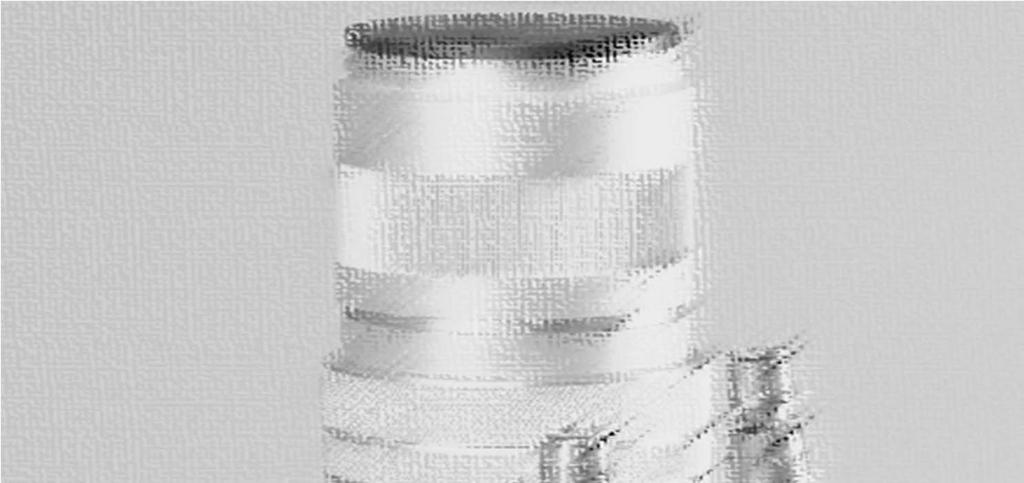
3 1 Introduction One of the key deliverables in the LaserSnake2 project is the development and assessment of an underwater laser cutting process. The desire and motivation for dismantling medium to high level nuclear waste underwater, is to significantly reduce contaminants escaping into the atmospheres and eliminate the logistics of handling and transporting such waste from the pond to the processing area. There is an increasing interest in the nuclear sector, particularly in the UK, to acquire an underwater cutting technology that could be versatile enough to both size reduce and decommission such waste. The primary benefits of dismantling nuclear waste underwater are to minimise production of secondary waste and reduce the complexity of remote operation. Currently, there are three underwater cutting technologies considered for dismantling structures in the nuclear industry: 1 Abrasive Water Jet: This technology is capable of cutting variety of materials, in varied depths and in thick-sections but it is inherently slow and produces significant secondary waste in the form of contaminated abrasive. 2 Diamond Wire Sawing: This technology is frequently used by oil and gas industries for dismantling of extremely large structures and can be used at extreme depths. However, such machines are large, heavy and contain complicated mechanisms for traversing the wire. The cost of deployment, running and final decommissioning of such cutting systems in nuclear decommissioning operations restricts the use of this technology in this sector. 3 Plasma Arc: This technology has proven itself to be cheap and reliable in cutting metallic materials, but mostly on planner geometries and it is used by the nuclear industry as well as the oil and gas sector. However, its use is inherently limited by standoff distance and electrically conductive and flat material geometries. Furthermore, the process produces a high level of secondary waste, and requires frequent nozzle changes, increasing operational time and costs. Laser technology, especially with recent development in fibre delivered beams, could offer a fourth choice to the nuclear industry. This report details the first phase of developments in underwater laser cutting nozzle design and the resulting process performance in cutting of thick-section C-Mn steel plates within the LaserSnake2 collaborative project. Because of the attenuation of fibre delivered laser light in water, the approach taken was to design a cutting nozzle that would create a dry zone in the immediate area of the interaction of the laser beam with the material being cut. 2 Objectives Design and manufacture an underwater laser cutting nozzle, capable of providing a dry zone at the point of cutting. Assess and characterise the operating performance of the underwater laser cutting nozzle, by identifying the maximum cut depth possible when using a 5kW continuouswave (CW) fibre laser. 3 Underwater Cutting Nozzle Design and Operation 3.1 Design Figure 1 shows a CAD design of the underwater cutting nozzle attachment. This system was designed to fit round an existing 250mm focal length cutting head. The housing was designed so that the position of the nozzle tip of the cutting head could be moved up and down with respect to the external housing. This facility allowed changes to be made to the cutting nozzle tip to workpiece stand-off distance, without changing the position of the focusing laser beam. In this way, the beam focus position, with respect to the surface of the material, remained constant as the stand-off distance varied /2/13 1 TWI Ltd
4 The external metal housing, which separated the water from the air space, could be replaced using a Perspex sleeve, so that it was possible to see the effect of the various air streams applied to sections inside the housing. The purpose of these air steams was to pressurise the inside of the housing removing the water inside and maintaining a dry zone, both at the cutting point and for the laser beam emerging from the cutting nozzle tip. In practice, the only part of the nozzle submerged under water during the trials, was that shown in Figure 2, due to concerns about the sealing of parts of the conventional laser cutting head used to focus and deliver the beam. The photograph in Figure 3 shows the laser beam focusing lens and protection cover slide module attached to the underwater cutting nozzle. Figure 1 CAD drawing of the underwater cutting nozzle. The underwater laser cutting nozzle provided three independent gas flow inlets: 1 A primary high pressure gas jet which flowed in the central of the system, co-axial with the laser beam (as found in conventional cutting heads). 2 A secondary annular gas nozzle surrounding the central cutting nozzle tip. This was designed to provide a first dry zone and minimise dynamic instabilities in the primary central high pressure cutting gas jet. 3 A tertiary static gas pressure chamber (the housing itself), to promote a much larger dry zone, provide an equilibrium pressure gradient between the primary and secondary gas jets, and in addition, prevent nozzle tips (and optics) from water and contamination. Figure 2 shows a schematic (through two orthogonal sections) of the housing showing the entry points of the primary, secondary and tertiary gas jets. The housing terminated with an annular nylon brush seal, which could move across the surface of the material being cut. The primary high pressure gas was delivered upstream to the underwater cutting head, while the gas to the secondary and tertiary inlets was provided via four connections on the top of the nozzle housing /2/13 2 TWI Ltd

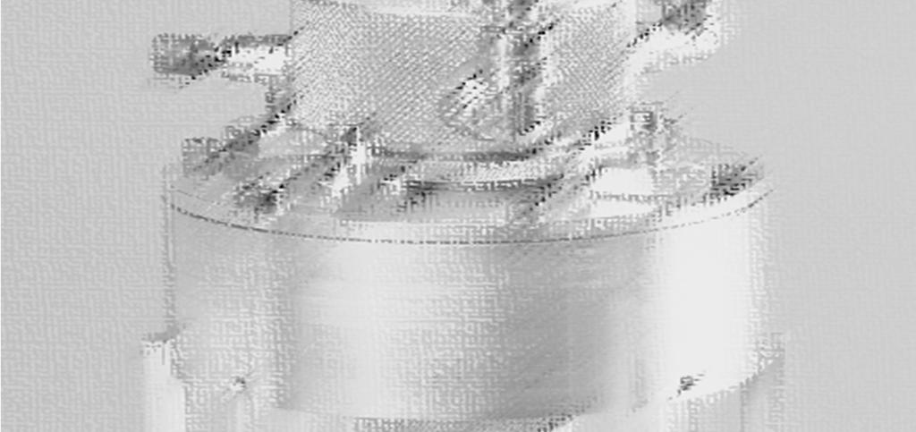
5 Figure 2 Underwater laser cutting process schematic. (Stand-off distance =15mm). 3.2 Dry-zone testing The underwater housing was connected to a set of standard focusing optics; in this case the focusing lens used had a focal length of 250mm. This assembly can be seen in Figure 3. In order to assess the performance of the secondary and tertiary inputs to the underwater nozzle and their capability to form a dry-zone, a series of trials were performed without using assist gas in the primary central gas jet. These tests were performed in three configurations and with nothing beneath the nozzle. 1 All four inputs to the housing were connected to the secondary annular gas jet. The gas to the four inputs was supplied with one common input to ensure equal gas pressure distribution. The whole underwater housing was lowered vertically into the water tank, and the cutting head was tilted to approximately 30 o with respect to vertical axis to allow the housing to be partially filled with water. Gas pressure to the four 4mm diameter inputs was applied via a single 6mm id hose, split into four individual tubes. Several tests were performed in this configuration, varying the gas pressure between 0.5 and 6bar. 2 Two inputs to the housing were connected to the secondary annular gas jet and the remaining two, to the tertiary input to the nozzle housing. Similarly to test 1, the housing was lowered into the water tank without the primary central gas jet being pressurised, and the system was tested at similar gas pressures to test 1, while tilting the head to 30 to the vertical axis. Similarly to test 1, the housing was partially filled with water and the displacement of water level in the tertiary chamber was monitored for each gas pressure setting /2/13 3 TWI Ltd

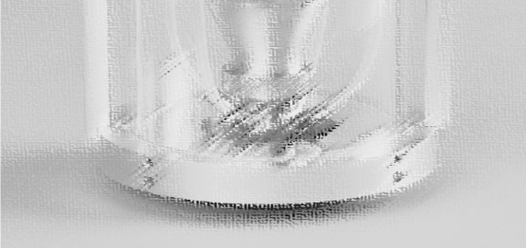
6 3 The third test arrangement was identical to the second test, but with one exception, that being that the tertiary nozzle housing was first allowed to completely fill with water. This was achieved by disconnecting the two gas inputs to the tertiary chamber and displacing the trapped air in the chamber with water. After the chamber was full, the gas connections were re-attached and pressurised to measure the time to evacuate the water from the chamber. In test 1, with no gas connection to the tertiary input, and with the nozzle in the vertical position, no change in the water level inside the tertiary chamber was noticed for changes in the secondary gas pressure. The water level was always maintained just above the brush seal. Gas pressure trials when the cutting head was tilted at the 30 o position, showed a slight increase in the water level inside the chamber. When two gas inputs were connected in tests 2 and 3 configurations, it was found that a moderate pressure of 0.5bar was sufficient to displace the water from the chamber within 0.4 seconds and maintain a dry zone. However, better performance was seen at higher pressures up to 4bars. As a result, the configuration in test 2 was chosen for the underwater laser cutting trials detailed below. Figure 4 shows the underwater cutting head in test 2 mode (without the primary assist gas jet), showing an inverted bell like air/water interface. Trials with the test 2 configuration were also carried out with the nozzle positioned on a workpiece. In this case, the bell like air/water interface disappeared and all gas was seen escaping the between the nylon brush seal and the workpiece surface. When activating the primary gas jet at 8 bar pressure, the gas escape route was still between the nylon brush and the workpiece surface, but with much higher turbulence. Figure 3 Focusing lens assembly connected to the underwater cutting housing /2/13 4 TWI Ltd

7 Figure 4 Lower part of the underwater housing pressurised with air. The brush seal can be seen and a bell like air/water interface. The secondary and the tertiary gas pressures were set to 4bar of compressed air pressure with no gas flow through the primary central gas jet. 4 Equipment and Materials used in the Underwater Cutting Trials For the underwater laser cutting trials, the following equipment and materials were used: An underwater laser cutting nozzle/head assembly designed and developed by TWI, as described above. A 1m 3 volume water tank, with water level sufficient to ensure that the underwater cutting nozzle was fully submerged. A JS30 Kawasaki robot to move the laser cutting head across the material surface in a straight line. A laser capable of transmitting its power though a 0.15mm diameter delivery fibre, which was coupled to the cutting head. The cutting head comprised of a 120mm collimating lens and a 250mm focusing lens, and both these optics were protected from contamination by a cover slide. The gas fed through the primary jet was supplied by a high pressure hose connected to a compressed air supply bank which contained 10 standard compressed cylinders. This high pressure assist gas was delivered through a 4mm diameter nozzle tip. The gas to the secondary and the tertiary inputs was provided by a compressor, and for all cutting trials 4 bar pressure was maintained before the four inputs. For the underwater cutting trials, samples from a 60mm thickness S355J2+N C-Mn steel plate, machined at 45 degrees were used. For additional trials, a variable thickness, 6 to 12mm epoxy painted S275JR C-Mn steel plate and 20 and 35mm thickness S355J2+N C-Mn steel plates were used. 5 Experimental Procedures Underwater Cutting In order to minimise the number of cutting trials, a 60mm thickness S355J2+N C-Mn steel plate was flame cut into a 45 o wedge. Simple linear cuts across the wedge shaped section, made with the laser beam axis pointing vertically downwards, (see Figure 5) were performed to assess the maximum cut depth attainable for cutting speeds ranging from 50 to 1000mm/min. For each cutting speed, the secondary and the tertiary gas supply was maintained at constant pressure of 4bar, whilst the primary central gas pressure (from now on referred to as the assist gas pressure) was varied between 2 and 8bar. In addition, for each combination of cutting speed and assist gas pressure, 4 stand-off distances (cutting nozzle tip to plate surface distance) were tested, ranging from 15 to 30mm. The standoff distance described here was between the tip of the primary gas jet and the workpiece, and was varied by introducing 5mm thickness spacers between the nozzle housing and the 22883/2/13 5 TWI Ltd

8 cutting nozzle. The standoff distance between end of the nylon brush and the workpiece was kept constant (~2mm) for all cutting trials. The emphasis in these experiments was to assess the effectiveness of the assist gas jet underwater. A constraint in the underwater cutting head design was the fixed laser focal position of 15mm above the material surface. For the 250mm focal length lens in use, this equates to a calculated laser beam diameter of 1.1mm on the material surface. In all the laser cutting trials, a constant laser power of 4.8kW was used and all cuts were performed with the samples at a water depth of 200mm. The underwater cutting procedure consisted of first charging the secondary and the tertiary parts of the cutting head with compressed air at a pressure of 4bar, when the nozzle assembly was located outside the tank. This gas supply was provided from the compressor. This procedure was seen to maintain the dry zone and also kept all optical surfaces from splashing with water. The robot was first programmed to index the nozzle and the cutting head to the start position relative to the workpiece, ensuring the chosen distance between the brush seal and the workpiece was always maintained by pre-programming the robot movement and performing a simulated cut without the laser and the assist gas jet. Just before commencing the cutting process, the laser beam and the assist gas jet were activated. This procedure was repeated for each set of parameters. For each parameter set, kerf width and maximum cut depth were measured, and the data recorded. The list of experimental parameters and their range is shown in the Table. Table Underwater laser cutting parameters Laser power Gas pressure Cutting speeds Standoff distances Lens focal length Focal position 4.8kW 2, 4 and 8bar 50 to 1000 mm/min 15 to 30mm 250mm +15mm 6 Results 6.1 Underwater trials Wedge shaped samples The assembly shown in Figure 3 was attached to a standard collimating unit and to the laser using a standard 150 micron diameter optical fibre. An example of linear cuts produced at different conditions on a 45 o wedge plate, 60mm in thickness is shown Figure 5. Figure 5 Linear cut tracks produced at standoff distance of 15mm for seven cutting speeds and two gas pressures /2/13 6 TWI Ltd
9 The maximum cut depths achieved with 4.8kW laser power, for 7 linear cutting speeds, 4 standoff distances, and 3 cutting/assist air pressures, are shown in Figures 6 to 8 respectively. A deeper cut depth was achieved at low cutting speed for all parameters and the cut depth exponentially decreased with increase in the cutting speed. There was no appreciable difference in maximum cut depths with variation in either the assist gas pressure or standoff distance, except when cutting at speeds below 200mm/min. A positive effect of the higher primary gas pressure of 8bar, on maximum cut depth, was observed for larger standoff distance but the increase in performance was relatively small. In all the cutting trials, use of a smaller standoff distance produced slightly deeper cut depth. Figure 6 Maximum underwater cut depths achieved as a function cutting speed using 2bar assist gas pressure and 4.8kW of laser power, at four standoff distances /2/13 7 TWI Ltd
10 Figure 7 Maximum underwater cut depths achieved as a function of cutting speed using 4bar assist gas pressure and 4.8kW of laser power, at four standoff distances. Figure 8 Maximum underwater cut depths achieved as a function of cutting speed using 8bar assist gas pressure and 4.8kW of laser power, at four standoff distances. Kerf widths measured for all parameter sets are shown in Figures 9 to 11, for assist gas pressures of 2, 4 and 8bar respectively. Unlike for maximum cut depth results, considerable difference in the measured kerf widths was noticed as a function of standoff distance and assist gas pressures. Generally, a larger nozzle to workpiece stand-off distance produced a larger kerf width, even though the laser beam focal diameter on the material surface was always maintained constant at the value of 1.1mm. The maximum and minimum kerf widths recorded were 2.1 and 1.1mm. At 2bar assist gas pressure, the kerf width was found to 22883/2/13 8 TWI Ltd
11 linearly decrease with the cutting speed. However, increasing the cutting/assist gas pressure to 4 and 8bar, the relationship was noticed to change to an exponential profile as the cutting speed was increased. This effect was most noticeable when cutting with gas pressure of 8bar. The following general trends were noticed from examining the wedge shaped samples: Higher cutting speed produced a lower cut depth. The amount of dross attached at the bottom of the workpiece surface increased with cut depth, and with lower cutting/assist (primary) gas jet pressure. Kerf widths measured for all conditions were between 1.1 and 2.1mm, and larger kerf widths were seen when cutting at slow speeds. Figure 9 Kerf width achieved as a function of cutting speed using 2bar air pressure and 4.8kW of laser power, at four standoff distances /2/13 9 TWI Ltd
12 Figure 10 Kerf width achieved as a function of cutting speed using 4bar air pressure and 4.8kW of laser power, at four standoff distances. Figure 11 Kerf width achieved as a function of cutting speed using 8bar air pressure and 4.8kW of laser power, at four standoff of distances Demonstration components For the demonstration components, three flat C-Mn steel plates, two with constant thicknesses of 20 and 35mm, and one with a variable thickness, from 6 to 12mm were chosen. Using the maximum cut depth results obtained for a primary gas pressure of 8bar and a standoff distance of 15mm in Figure 8, the corresponding expected cut depths and cutting speeds for each demonstrator were identified and chosen. Using these identified 22883/2/13 10 TWI Ltd
 b) Figure 12 Sections of underwater laser cut samples: a) Variable thickness (6 to 12mm) S275JR C-Mn steel plate cut at 500mm/min; b) 20mm thickness S355J2+N C-Mn steel plate cut at 200mm/min; c)")
, where maximum cutting speeds 1100mm/min and 300mm/min (using 4.")
, the underwater cutting results indicated ~50% reduction in cutting speed (for an equivalent thickness).")
13 conditions all three materials were cut, and the sections of these underwater cut samples are shown in Figure 12. a) b) Figure 12 Sections of underwater laser cut samples: a) Variable thickness (6 to 12mm) S275JR C-Mn steel plate cut at 500mm/min; b) 20mm thickness S355J2+N C-Mn steel plate cut at 200mm/min; c) 35mm thickness S355J2+N C-Mn steel plate cut at 50mm/min. 7 Discussion Laser cutting of S275JR C-Mn steel in a dry environment were reported in LaserSnake1 (TP ), where maximum cutting speeds 1100mm/min and 300mm/min (using 4.8kW of laser power, 8bar assist gas pressure, a beam focal position located at the material surface and with a 250mm focal length lens) were achieved for material thicknesses of 12 and 25mm respectively. In comparison, (with the exception of beam focus position), the underwater cutting results indicated ~50% reduction in cutting speed (for an equivalent thickness). The cut quality achieved in the dry environment showed cleaner kerfs and less dross when compared with the underwater results. Particularly, a significant difference in the dross formation was noticed with the underwater cutting process. The amount of dross attached at the kerf exit with underwater process was seen to increase with cut depth, and with lower cutting gas pressure. In decommissioning of nuclear materials, excess dross attachment to the cut sample may be desirable as this may lock in more contaminated material, which otherwise would discharge in the water, and thus result in reduced secondary waste Analysis of Figures 6 to 8 indicates that there was no appreciable difference in maximum cut depth with variations in the assist gas pressure, for all standoff distances evaluated. However, a slight increase in the cut depth was seen as a function of standoff distances at lower cutting speeds. This suggests that the gas flow inside the kerf is nearly the same for nearly all pressure conditions. This minimal difference in cutting performance was noticed between the two standoff distances of 15 and 30mm, but was found to be limited to cutting speeds below 200mm/min; a standoff distance of 15mm resulted in a higher cut depth, when the cutting speed was lower than 200mm/min. A positive effect of 8bar gas pressure on the maximum cut depth, was observed for larger standoff distance, but the increase in performance was relatively small (0.5% to 7% for a 15mm standoff, and 4% to 17% for a standoff of 30mm, between 8 and 2bar assist gas pressures). In this work, generally higher assist gas pressure produced smaller kerf widths and the largest kerf width was produced with the higher standoff distance of 30mm, even though the focal position was experimentally the same for all cutting conditions. This may indicate a variation in the laser beam diameter (laser power intensity) on the material surface due to possible variations in the refractive index of a mixed phase (water vapour (steam) & air) medium inside the kerf width. Nevertheless, one would normally expect a higher contrast in cut depths as a function of standoff distance, because of the variation in the kerf width c) 22883/2/13 11 TWI Ltd
14 seen. This was not noticed and may be due to insufficient gas jet momentum produced by use of only 2bar assist gas pressure. It is also likely that material removal rate was higher with the 8bar assist gas pressure, but due to convection cooling from the water, the ejected material solidified as dross inside and at the end of the narrow kerf exit, requiring additional laser energy for complete break through. The relationship between kerf width, assist gas pressure, cutting speed and cut depth, requires addressing in more detail, by taking into account the additional parameter of beam focal position, in future underwater cutting trials. 8 Conclusions Experimental trials performed with the prototype nozzle have allowed the following conclusions to be drawn: An underwater laser cutting nozzle has been designed, manufactured and tested, which showed good potential for creating and maintaining during cutting, of a dry-zone on the material surface. Using the laser power available, the maximum cut depth in S355J2+N C-Mn steel was 38mm. This was achieved at a travel speed of 50mm/min. Higher cut depth was achieved with a slower cutting speed and increased cut depths produced larger attached dross volume at the kerf exit. The attached dross volume was also seen to increase when cutting with lower assist gas pressure Assist gas pressure had very little effect on the maximum cut depth for most standoff distances, but a slight increase in performance with 8bar assist gas pressure was observed when cutting with the larger standoff distances. Variations in kerf width were more noticeable than variations in the maximum cut depth. At higher assist gas pressure, a larger kerf width allowed more gas to escape through the laser cut channel, resulting in a slight increase in the cut depth. The present underwater prototype nozzle design was found to be quite insensitive to assist gas pressure or standoff distance, over the range of values used in these experiments. This indicates that modest assist gas pressures will be able to produce reasonable underwater cutting performance, which will be a very desirable requirement when laser cutting contaminated material underwater. 9 Acknowledgements The author would like to thank Frank Nolan who conducted the cutting trials. LaserSnake2 is co-funded by the Technology Strategy Board, the Department of Energy and Climate Change, and the Nuclear Decommissioning Authority, under grant number Disclaimer The data and results contained within this report are advisory in nature, expressed as an opinion only and no warranty, expressed or implied, is given as to the suitability of such advice or results for any particular purpose. The information made available by TWI Ltd over the World Wide Web does not form part of any contract. Whilst every effort has been made to ensure the accuracy of the information presented, TWI Ltd cannot accept responsibility for any errors /2/13 12 TWI Ltd
Development of underwater laser cutting technique for steel and zircaloy for nuclear applications
 PRAMANA c Indian Academy of Sciences Vol. 75, No. 6 journal of December 2010 physics pp. 1253 1258 Development of underwater laser cutting technique for steel and zircaloy for nuclear applications R K
Powermax machine-side reference guide For mechanized applications with Powermax1000, Powermax1250 and Powermax1650
 Powermax machine-side reference guide For mechanized applications with Powermax1000, Powermax1250 and Powermax1650 This Powermax machine-side reference guide is a supplement to your Operator Manual and
Development of a High Pressure, Oil Free, Rolling Piston Compressor
 Purdue University Purdue e-pubs International Compressor Engineering Conference School of Mechanical Engineering 1994 Development of a High Pressure, Oil Free, Rolling Piston Compressor S. J. Delmotte
CHARACTERISTICS OF AN AIR-COATED ABRASIVE SUSPENSION JET UNDER SUBMERGED CONDITION
 2013 WJTA-IMCA Conference and Expo September 9-11, 2013 Houston, Texas Paper CHARACTERISTICS OF AN AIR-COATED ABRASIVE SUSPENSION JET UNDER SUBMERGED CONDITION H. Ito, G. Peng and S. Shimizu College of
Lab # 03: Visualization of Shock Waves by using Schlieren Technique
 AerE545 Lab # 03: Visualization of Shock Waves by using Schlieren Technique Objectives: 1. To get hands-on experiences about Schlieren technique for flow visualization. 2. To learn how to do the optics
Design of a Solid Wall Transonic Wind Tunnel
 Design of a Solid Wall Transonic Wind Tunnel David Wall * Auburn University, Auburn, Alabama, 36849 A solid wall transonic wind tunnel was designed with optical access from three sides to allow for flow
OPERATION. Estimated kerf width compensation. HPR260 Manual Gas Instruction Manual 4-9
 Estimated kerf width compensation The widths in the chart below are for reference. Differences between installations and material composition may cause the specific user results to vary from those shown
Experimental Analysis on Vortex Tube Refrigerator Using Different Conical Valve Angles
 International Journal of Engineering Research and Development e-issn: 7-067X, p-issn: 7-00X, www.ijerd.com Volume 3, Issue 4 (August ), PP. 33-39 Experimental Analysis on Vortex Tube Refrigerator Using
Free Surface Flow Simulation with ACUSIM in the Water Industry
 Free Surface Flow Simulation with ACUSIM in the Water Industry Tuan Ta Research Scientist, Innovation, Thames Water Kempton Water Treatment Works, Innovation, Feltham Hill Road, Hanworth, TW13 6XH, UK.
Multifunctional Screw Compressor Rotors
 Multifunctional Screw Compressor Rotors Nikola Stosic, Ian K. Smith and Ahmed Kovacevic Centre for Positive Displacement Compressor Technology, City University, London EC1V OHB, U.K. N.Stosic@city.ac.uk
HiFocus 280i / 360i / 440i
 Plasma Systems i / i / i of Metals from 0.5 up to 100 mm made in Germany Plasma cost-efficient and flexible as never before Plasma cost-effcient and flexible as never before If cutting shops and users
AIAA Brush Seal Performance Evaluation. P. F. Crudgington Cross Manufacturing Co. Ltd. Devizes, ENGLAND
 AIAA 98-3172 Brush Seal Performance Evaluation P. F. Crudgington Cross Manufacturing Co. Ltd. Devizes, ENGLAND BRUSH SEAL PERFORMANCE EVALUATION AIAA-98-3172 P. F. Crudgington Cross Manufacturing Co. Ltd
The Usage of Propeller Tunnels For Higher Efficiency and Lower Vibration. M. Burak Şamşul
 The Usage of Propeller Tunnels For Higher Efficiency and Lower Vibration M. Burak Şamşul ITU AYOC 2014 - Milper Pervane Teknolojileri Company Profile MILPER is established in 2011 as a Research and Development
Relative Dosimetry. Photons
 Relative Dosimetry Photons What you need to measure! Required Data (Photon) Central Axis Percent Depth Dose Tissue Maximum Ratio Scatter Maximum Ratio Output Factors S c & S cp! S p Beam profiles Wedge
Technical Data Sheet TI-F50 Locking Units series KFH
 English translation of German original Locking Units series KF Further important practical advice is given in Operating Manual BA-F50., Rod diameter 18 mm 50 mm øz 8 L 2 6 x 6 0 min. 4x30 KF 18 to KF 32,
Linear Compressor Discharge Manifold Design For High Thermal Efficiency
 Purdue University Purdue e-pubs International Compressor Engineering Conference School of Mechanical Engineering 2016 Linear Compressor Discharge Manifold Design For High Thermal Efficiency Dietmar E.
4 Machine maintenance and repair
 3.3 lift device consists of: lift motor, lead screw, guide rod, lifting seat Lift motor Lead screw Guide rod Lifting seat Diagram 3.3 3.4 torch holder set The torch holder consist of holder connection,
COMPUTATIONAL FLOW MODEL OF WESTFALL'S LEADING TAB FLOW CONDITIONER AGM-09-R-08 Rev. B. By Kimbal A. Hall, PE
 COMPUTATIONAL FLOW MODEL OF WESTFALL'S LEADING TAB FLOW CONDITIONER AGM-09-R-08 Rev. B By Kimbal A. Hall, PE Submitted to: WESTFALL MANUFACTURING COMPANY September 2009 ALDEN RESEARCH LABORATORY, INC.
Experimental Determination of Temperature and Pressure Profile of Oil Film of Elliptical Journal Bearing
 International Journal of Advanced Mechanical Engineering. ISSN 2250-3234 Volume 4, Number 5 (2014), pp. 469-474 Research India Publications http://www.ripublication.com Experimental Determination of Temperature
Hermetic Compressor Manifold Analysis With the Use of the Finite Element Method
 Purdue University Purdue e-pubs International Compressor Engineering Conference School of Mechanical Engineering 2008 Hermetic Compressor Manifold Analysis With the Use of the Finite Element Method Rinaldo
L 100. Bubble-Tube Level System. Installation, Operation and Maintenance Instructions
 L 100 Bubble-Tube Level System Installation, Operation and Maintenance Instructions Figure 1 Contents Section Description Page 1.0 Introduction 2 2.0 Specifications 3 3.0 Installation 3 4.0 Warranty 6
Micro Channel Recuperator for a Reverse Brayton Cycle Cryocooler
 Micro Channel Recuperator for a Reverse Brayton Cycle Cryocooler C. Becnel, J. Lagrone, and K. Kelly Mezzo Technologies Baton Rouge, LA USA 70806 ABSTRACT The Missile Defense Agency has supported a research
MODELLING OF FUME EXTRACTORS C. R.
 LD8 19th International Symposium of Ballistics, 7 11 May 21, Interlaken, Switzerland MODELLING OF FUME EXTRACTORS C. R. Woodley WS4 Guns and Warheads Department, Defence Evaluation and Research Agency,
Pilot Operated Safety Relief Valves For Liquified Gas Carriers
 Pilot Operated Safety Relief Valves For Liquified Gas Carriers LUCET Features and dvantages High seat tightness - s the force that holds the disc on the nozzle increases with the pressure, the valve remains
Tradition & Technology
 Gaterotor Support Gaterotor Single Screw Compressors Design & Operation Bearing Bearings Main Screw Parallex Slide System The VSM Single Screw Compressor has one main rotor and two gaterotors. All bearings
Mild steel. Stainless steel. HPR130XD Auto Gas Revision 2. Nozzle retaining cap. tube. Shield cap 30 A 50 A 80 A 130 A
 Operation Mild steel cap Nozzle retaining cap Nozzle Swirl ring Electrode 220194 220754 220193 220180 220192 220555 220754 220554 220553 220552 Water tube 30 A 50 A 220340 220747 80 A 220189 220756 220188
STRIP EDGE SHAPE CONTROL
 STRIP EDGE SHAPE CONTROL Gary Boulton, Tino Domanti, Terry Gerber, Glen Wallace Industrial Automation Services The control of shape in the strip edge region remains a significant challenge for shape control
ZIN Technologies PHi Engineering Support. PHi-RPT CFD Analysis of Large Bubble Mixing. June 26, 2006
 ZIN Technologies PHi Engineering Support PHi-RPT-0002 CFD Analysis of Large Bubble Mixing Proprietary ZIN Technologies, Inc. For nearly five decades, ZIN Technologies has provided integrated products and
Review of fundamental photon dosimetry quantities
 Review of fundamental photon dosimetry quantities Narayan Sahoo Main sources of the materials included in this lecture notes are: (1) Radiation Oncology Physics: A Handbook for Teachers and Students Edited
CONSIDERATION OF DENSITY VARIATIONS IN THE DESIGN OF A VENTILATION SYSTEM FOR ROAD TUNNELS
 - 56 - CONSIDERATION OF DENSITY VARIATIONS IN THE DESIGN OF A VENTILATION SYSTEM FOR ROAD TUNNELS Gloth O., Rudolf A. ILF Consulting Engineers Zürich, Switzerland ABSTRACT This article investigates the
Experiment (13): Flow channel
: Flow channel") Experiment (13): Flow channel Introduction: An open channel is a duct in which the liquid flows with a free surface exposed to atmospheric pressure. Along the length of the duct, the pressure at the surface
Experiment (13): Flow channel Introduction: An open channel is a duct in which the liquid flows with a free surface exposed to atmospheric pressure. Along the length of the duct, the pressure at the surface
Injector Dynamics Assumptions and their Impact on Predicting Cavitation and Performance
 Injector Dynamics Assumptions and their Impact on Predicting Cavitation and Performance Frank Husmeier, Cummins Fuel Systems Presented by Laz Foley, ANSYS Outline Overview Computational Domain and Boundary
Modelling of Pressurised Pipes within InfoWorks ICM and CS
 Modelling of Pressurised Pipes within InfoWorks ICM and CS 1. Introduction Correctly modelling pressurised pipes, variously described as forcemains or rising mains, can be one of the more difficult aspects
Fully Submersible Heavy Lift Vessel
 Fully Submersible Heavy Lift Vessel Arnbjorn Joensen Aberdeen Maritime Branch (28th January 2015) PRESENTATION Introduction to the Subsea Deployment Vessel Installation method Tank test video Potential
SHELL FLAGS INSPECTION CASE STUDY
 SHELL FLAGS INSPECTION CASE STUDY J. Nonemaker, Solution Engineer, ROSEN T. Steinvoorte, Business Development, ROSEN R. Subramanian, Pipelines & Subsea Technical Support Engineer, Shell U.K. Limited Introduction
HANDBOOK. Squeeze Off Unit SOU 400. Please refer any queries to:
 HANDBOOK Squeeze Off Unit SOU 400 Please refer any queries to: Hy Ram Engineering Co Ltd Pelham Street Mansfield Nottinghamshire NG18 2EY Telephone No: (01623) 422982 Please note all queries should state
Characterizers for control loops
 Characterizers for control loops By: F. G. Shinskey (May 1999) Introduction Commercial controllers such as the PID series (proportional, integral, derivative, and their combinations) are linear devices
ENSURING AN ACCURATE RESULT IN AN ANALYTICAL INSTRUMENTATION SYSTEM PART 1: UNDERSTANDING AND MEASURING TIME DELAY
 ENSURING AN ACCURATE RESULT IN AN ANALYTICAL INSTRUMENTATION SYSTEM PART 1: UNDERSTANDING AND MEASURING TIME DELAY Process measurements are instantaneous, but analyzer responses never are. From the tap
LaserSnake2. Presentations by LaserSnake partners and Sellafield Ltd at TWI. 21 st September 2016
 LaserSnake2 Presentations by LaserSnake partners and Sellafield Ltd at TWI 21 st September 2016 1 LaserSnake2 Tele-robotic delivery of laser cutting for nuclear decommissioning 2 Decommissioning challenges
Gas Gathering System Modeling The Pipeline Pressure Loss Match
 PETROLEUM SOCIETY CANADIAN INSTITUTE OF MINING, METALLURGY & PETROLEUM PAPER 2005-230 Gas Gathering System Modeling The Pipeline Pressure Loss Match R.G. MCNEIL, P.ENG. Fekete Associates Inc. D.R. LILLICO,
Understanding How the Appearance of Optical Fiber Splices Relates to Splice Quality
 Understanding How the Appearance of Optical Fiber Splices Relates to Splice Quality Douglas Duke & David Mansperger Fusion Splicing Systems, AFL, Duncan, SC Doug.Duke@AFLglobal.com David.Mansperger@AFLglobal.com
AIR EJECTOR WITH A DIFFUSER THAT INCLUDES BOUNDARY LAYER SUCTION
 Engineering MECHANICS, Vol. 20, 2013, No. 3/4, p. 213 220 213 AIR EJECTOR WITH A DIFFUSER THAT INCLUDES BOUNDARY LAYER SUCTION Václav Dvořák* The article deals with axial-symmetric subsonic air-to-air
A NEW PROCESS FOR IMPROVED LIQUEFACTION EFFICIENCY
 WHITE PAPER A NEW PROCESS FOR IMPROVED LIQUEFACTION EFFICIENCY Author(s): Adam Jones and Grant Johnson, Costain Natural Resources First published: GPAE, September 2014 www.costain.com A New Process for
Flow transients in multiphase pipelines
 Flow transients in multiphase pipelines David Wiszniewski School of Mechanical Engineering, University of Western Australia Prof. Ole Jørgen Nydal Multiphase Flow Laboratory, Norwegian University of Science
AIRFLOW GENERATION IN A TUNNEL USING A SACCARDO VENTILATION SYSTEM AGAINST THE BUOYANCY EFFECT PRODUCED BY A FIRE
 - 247 - AIRFLOW GENERATION IN A TUNNEL USING A SACCARDO VENTILATION SYSTEM AGAINST THE BUOYANCY EFFECT PRODUCED BY A FIRE J D Castro a, C W Pope a and R D Matthews b a Mott MacDonald Ltd, St Anne House,
Cutting and shaping materials using thermal cutting equipment
 Unit 824 Cutting and shaping materials using thermal cutting equipment UAN: H/600/5883 Level: Level 2 Credit value: 14 GLH: 64 Relationship to NOS: This unit has been derived from national occupational
Pore-Air Entrapment during Infiltration
 Pore-Air Entrapment during Infiltration GEO-SLOPE International Ltd. www.geo-slope.com 1200, 700-6th Ave SW, Calgary, AB, Canada T2P 0T8 Main: +1 403 269 2002 Fax: +1 888 463 2239 Introduction Infiltration
In the liquid phase, molecules can flow freely from position. another. A liquid takes the shape of its container. 19.
 In the liquid phase, molecules can flow freely from position to position by sliding over one another. A liquid takes the shape of its container. In the liquid phase, molecules can flow freely from position
The Impact of Security Bollards on Evacuation Flow
 The Impact of Security Bollards on Evacuation Flow E.R. Galea, D. Cooney, G.G. Sharp, S. Gwynne 1 Fire Safety Engineering Group, University of Greenwich, UK Formerly at UoG, now at National Research Council,
MACH ONE MASS FLOW CONTROLLER. MACH ONE SERIES flow control. MASS FLOW CONTROLLERS at the speed of sound.
 MACH ONE MASS FLOW CONTROLLER MACH ONE SERIES flow control MASS FLOW CONTROLLERS at the speed of sound. MACH ONE SERIES MASS FLOW CONTROLLER FLOW CONTROL AT THE SPEED OF SOUND The Mach One revolutionary
In the liquid phase, molecules can flow freely from position to position by sliding over one another. A liquid takes the shape of its container.
 In the liquid phase, molecules can flow freely from position to position by sliding over one another. A liquid takes the shape of its container. In the liquid phase, molecules can flow freely from position
Applied Fluid Mechanics
 Applied Fluid Mechanics 1. The Nature of Fluid and the Study of Fluid Mechanics 2. Viscosity of Fluid 3. Pressure Measurement 4. Forces Due to Static Fluid 5. Buoyancy and Stability 6. Flow of Fluid and
PANACEA P200 STAINLESS STEEL USER MANUAL
 Basic Features Stainless Steel body with 1.75 outside diameter. Will fit into wells down to 2 (schedule 80). Has an internal chamber volume of 200mL. Maximum depth below ground surface of 3000ft. Other
A STUDY OF THE LOSSES AND INTERACTIONS BETWEEN ONE OR MORE BOW THRUSTERS AND A CATAMARAN HULL
 A STUDY OF THE LOSSES AND INTERACTIONS BETWEEN ONE OR MORE BOW THRUSTERS AND A CATAMARAN HULL L Boddy and T Clarke, Austal Ships, Australia SUMMARY CFD analysis has been conducted on a 100m catamaran hull
Another convenient term is gauge pressure, which is a pressure measured above barometric pressure.
 VACUUM Theory and Applications Vacuum may be defined as the complete emptiness of a given volume. It is impossible to obtain a perfect vacuum, but it is possible to obtain a level of vacuum, defined as
PHYS 101 Previous Exam Problems
 PHYS 101 Previous Exam Problems CHAPTER 14 Fluids Fluids at rest pressure vs. depth Pascal s principle Archimedes s principle Buoynat forces Fluids in motion: Continuity & Bernoulli equations 1. How deep
TECHNICAL BULLETIN CRYOGENIC APPLICATION SERVICES. website:
 TECHNICAL BULLETIN SERVICES website: email: www.pipingtech.com info@pipingtech.com copyright 2009 Piping Technology & Products, Inc. SERVICES Objective TECHNICAL BULLETIN To determine the amount of ice
CHAPTER 2 EXPERIMENTAL SETUP AND PROCEDURE
 22 CHAPTER 2 EXPERIMENTAL SETUP AND PROCEDURE 2.1 EXPERIMENTAL COLUMN All the experiments were carried out in an internal loop airlift fluidized bed and combined loop fluidized bed (an external down comer
Vortex Tube Short Course February 2017
 Vortex Tube Short Course February 2017 10125 Carver Rd. Cincinnati, OH 45242 1.800.441.7475 sales@vortec.com Vortex Tube Short Course The vortex tube has been around for decades, yet occasionally it is
Development of Scroll Compressors for R410A
 Purdue University Purdue e-pubs International Compressor Engineering Conference School of Mechanical Engineering 2004 Development of Scroll Compressors for R410A Nobuhiro Nojima Takahiro Uematsu Takashi
PRC CO ² -LASER PRESENTATION
 Page 1 of 7 PRC CO ² -LASER PRESENTATION GENERAL CHARACTERISTICS - Embedded PC104 Electronics with exchangeable software allowing very easy integration of customer specified functions: such as eg. specific
Purge Star & Ring Purge Systems
 March 2013 Operator s Manual Purge Star & Ring Purge Systems Additional instruction for Purge Star Single Hose, Purge Star Double (bypass) Hose and Ring Purge with bypass hose and gas dump valve feature.
Investigation on Divergent Exit Curvature Effect on Nozzle Pressure Ratio of Supersonic Convergent Divergent Nozzle
 RESEARCH ARTICLE OPEN ACCESS Investigation on Divergent Exit Curvature Effect on Nozzle Pressure Ratio of Supersonic Convergent Divergent Nozzle Shyamshankar.M.B*, Sankar.V** *(Department of Aeronautical
The Cyclone Tire Deflation & Inflation Tool
 The Cyclone Tire Deflation & Inflation Tool How it works; This tool operates on compressed air that activates our patent pending venturi that creates a ultra-high vacuum, that draws the air from inside
Investigation of Thermal Effects of CO 2 on Earth-Atmosphere System
 Investigation of Thermal Effects of CO 2 on Earth-Atmosphere System Design Team Michel Beguin, Tim Bevins Dan Jakiela, Frank Kuchinski Design Advisor Prof. Yiannis Levendis Abstract This Capstone Project
RICK FAUSEL, BUSINESS DEVELOPMENT ENGINEER TURBOMACHINERY CONTROL SYSTEM DESIGN OBJECTIVES
 RICK FAUL, BUSINESS DEVELOPMENT ENGINEER TURBOMACHINERY CONTROL SYSTEM DESIGN OBJECTIVES The primary design objective for any turbomachinery control system should be to maintain or maximize machine and
NUMERICAL INVESTIGATION OF THE FLOW BEHAVIOUR IN A MODERN TRAFFIC TUNNEL IN CASE OF FIRE INCIDENT
 - 277 - NUMERICAL INVESTIGATION OF THE FLOW BEHAVIOUR IN A MODERN TRAFFIC TUNNEL IN CASE OF FIRE INCIDENT Iseler J., Heiser W. EAS GmbH, Karlsruhe, Germany ABSTRACT A numerical study of the flow behaviour
Experiment 8: Minor Losses
 Experiment 8: Minor Losses Purpose: To determine the loss factors for flow through a range of pipe fittings including bends, a contraction, an enlargement and a gate-valve. Introduction: Energy losses
LP Separator Level Control by Variable Speed and Multi Stage Brine Reinjection Pumps at Kawerau and Nga Awa Purua Geothermal Projects, New Zealand
 Proceedings World Geothermal Congress 2010 Bali, Indonesia, 25-29 April 2010 LP Separator Level Control by Variable Speed and Multi Stage Brine Reinjection Pumps at Kawerau and Nga Awa Purua Geothermal
University of Cincinnati
 Mapping the Design Space of a Recuperated, Recompression, Precompression Supercritical Carbon Dioxide Power Cycle with Intercooling, Improved Regeneration, and Reheat Andrew Schroder Mark Turner University
Digiquartz Water-Balanced Pressure Sensors for AUV, ROV, and other Moving Underwater Applications
 Digiquartz Water-Balanced Pressure Sensors for AUV, ROV, and other Moving Underwater Applications Dr. Theo Schaad Principal Scientist Paroscientific, Inc. 2002 Paroscientific, Inc. Page 1 of 6 Digiquartz
AIRMOUNT VIBRATION ISOLATION
 MOUNT VIBRATION ISOLATION SELECTION AND ISOLATION FORMULA Refer to the selection guide on page 33 for Airmount load and isolation capabilities. Follow this procedure: 1. LOAD CAPACITY Select one or two
Linear Compressor Suction Valve Optimization
 Purdue University Purdue e-pubs International Compressor Engineering Conference School of Mechanical Engineering 2016 Linear Compressor Suction Valve Optimization Rinaldo Puff Embraco, Brazil, rinaldo.puff@embraco.com
Fully Submersible Heavy Lift Vessel
 Fully Submersible Heavy Lift Vessel Arnbjorn Joensen Oil and Gas Authority (OGA) (15th February 2016) CONTENT Leadon structures demobilisation Competitiveness (case studies) Decommissioning options Installation
Development of Technology to Estimate the Flow Field around Ship Hull Considering Wave Making and Propeller Rotating Effects
 Development of Technology to Estimate the Flow Field around Ship Hull Considering Wave Making and Propeller Rotating Effects 53 MAKOTO KAWABUCHI *1 MASAYA KUBOTA *1 SATORU ISHIKAWA *2 As can be seen from
A New Piston Gauge to Improve the Definition of High Gas Pressure and to Facilitate the Gas to Oil Transition in a Pressure Calibration Chain
 A New iston Gauge to Improve the Definition of High Gas ressure and to Facilitate the Gas to Oil Transition in a ressure Calibration Chain ierre Delajoud, Martin Girard DH Instruments, Inc. 4765 East Beautiful
INTERACTION BETWEEN WIND-DRIVEN AND BUOYANCY-DRIVEN NATURAL VENTILATION Bo Wang, Foster and Partners, London, UK
 INTERACTION BETWEEN WIND-DRIVEN AND BUOYANCY-DRIVEN NATURAL VENTILATION Bo Wang, Foster and Partners, London, UK ABSTRACT Ventilation stacks are becoming increasingly common in the design of naturally
Investigation of Suction Process of Scroll Compressors
 Purdue University Purdue e-pubs International Compressor Engineering Conference School of Mechanical Engineering 2006 Investigation of Suction Process of Scroll Compressors Michael M. Cui Trane Jack Sauls
Assembly and measurements of a mechanical prototype of the BIS MDT chamber
 ATLAS Internal Note MUON NO 243 9 June 1998 Assembly and measurements of a mechanical prototype of the BIS MDT chamber K. Ekonomou Physics Department, Aristotle University of Thessaloniki, Thessaloniki,
WIND-INDUCED LOADS OVER DOUBLE CANTILEVER BRIDGES UNDER CONSTRUCTION
 WIND-INDUCED LOADS OVER DOUBLE CANTILEVER BRIDGES UNDER CONSTRUCTION S. Pindado, J. Meseguer, J. M. Perales, A. Sanz-Andres and A. Martinez Key words: Wind loads, bridge construction, yawing moment. Abstract.
Vibration-Free Joule-Thomson Cryocoolers for Distributed Microcooling
 Vibration-Free Joule-Thomson Cryocoolers for Distributed Microcooling W. Chen, M. Zagarola Creare Inc. Hanover, NH, USA ABSTRACT This paper reports on an innovative concept for a space-borne Joule-Thomson
New Energy-saving Air Compressors
 FEATURED ARTICLES Environmentally Conscious Technology in Industrial Fields Aiming for a Low-carbon Society New Energy-saving Air Compressors Air compressors produce compressed air and have a wide variety
Citation Journal of Thermal Science, 18(4),
,") NAOSITE: Nagasaki University's Ac Title Author(s) Noise characteristics of centrifuga diffuser (Noise reduction by means leading tip) Murakami, Tengen; Ishida, Masahiro; Citation Journal of Thermal Science,
NAOSITE: Nagasaki University's Ac Title Author(s) Noise characteristics of centrifuga diffuser (Noise reduction by means leading tip) Murakami, Tengen; Ishida, Masahiro; Citation Journal of Thermal Science,
True Hole technology frequently asked questions
 True Hole technology frequently asked questions What is True Hole technology? Hypertherm s patent pending True Hole cutting technology produces significantly better hole quality than what has been previously
Copyright by Turbomachinery Laboratory, Texas A&M University
 Proceedings of the 2 nd Middle East Turbomachinery Symposium 17 20 March, 2013, Doha, Qatar Effectiveness of Windage Features on High Speed Couplings Steven Pennington Global Engineering Manager John Crane
INSTRUMENTS A THERMAL MASS FLOW SENSOR USING A CONSTANT DIFFERENTIAL TEMPERATURE ABOVE THE AMBIENT GAS TEMPERATURE
 TELEDYNE HASTINGS TECHNICAL PAPERS INSTRUMENTS A THERMAL MASS FLOW SENSOR USING A CONSTANT DIFFERENTIAL TEMPERATURE ABOVE THE AMBIENT GAS TEMPERATURE Proceedings of FEDSM 98 1998 ASME Fluids Engineering
METROLOGY LAB. I DEVICES BASED ON VERNIER SCALE
 METROLOGY LAB. I DEVICES BASED ON VERNIER SCALE Indirect Measurement; two balls 2 Lab6: Roundness Test 12/1/2017 Indirect Measurement; four balls 3 Lab6: Roundness Test 12/1/2017 Angle measurement using
INSPECTION OF MULTI-DIAMETER PIPELINES OPERATING AT LOW PRESSURE. Stefan Vages > ROSEN Group
 INSPECTION OF MULTI-DIAMETER PIPELINES OPERATING AT LOW PRESSURE Stefan Vages > ROSEN Group PIPELINE TECHNOLOGY JOURNAL 7 ABSTRACT Particularly in the 1940s and 1950s, gas pipeline systems were not necessarily
FLOMIXERS SELECTION DATA ALL GASES
 MODEL: 2301 Revision: 0 BULLETIN 2301-2311 FLOMIXERS are proportional mixing devices that utilize the energy of a stream of air at pressures up to several pounds to (1) entrain a combustible gas, and (2)
Computer Simulation Helps Improve Vertical Column Induced Gas Flotation (IGF) System
 System") JOURNAL ARTICLES BY FLUENT SOFTWARE USERS JA187 Computer Simulation Helps Improve Vertical Column Induced Gas Flotation (IGF) System Computer simulation has helped NATCO engineers make dramatic improvements
JOURNAL ARTICLES BY FLUENT SOFTWARE USERS JA187 Computer Simulation Helps Improve Vertical Column Induced Gas Flotation (IGF) System Computer simulation has helped NATCO engineers make dramatic improvements
Next Generation Quartz Pressure Gauges
 Next Generation Quartz Pressure Gauges Rick Puccio, Ph.D. Senior Scientist Quartzdyne Houston, TX March 2, 2016 Outline Quartz Pressure Gauge Introduction Gauge Size Reduction Long Term Pressure Drift
256 Pneumatic Pressure Indicator
 256 Pneumatic Pressure Indicator 51425699 Copyright 2002 Slope Indicator Company. All Rights Reserved. This equipment should be installed, maintained, and operated by technically qualified personnel. Any
Experimental Verification of Integrated Pressure Suppression Systems in Fusion Reactors at In-Vessel Loss-of -Coolant Events
 Experimental Verification of Integrated Pressure Suppression Systems in Fusion Reactors at In-Vessel Loss-of -Coolant Events K. Takase 1), H. Akimoto 1) 1) Japan Atomic Energy Research Institute (JAERI),
Ingersoll Rand. X-Series System Automation
 Ingersoll Rand -Series System Automation Energy Savings on Demand! Ingersoll Rand As much as 20% to 60% of the energy used to operate compressed air systems is wasted. This is primarily due to operating
Figure 1 Schematic of opposing air bearing concept
 Theoretical Analysis of Opposing Air Bearing Concept This concept utilizes air bearings to constrain five degrees of freedom of the optic as shown in the figure below. Three pairs of inherently compensated
ACCURACY, PERFORMANCE, AND HANDLING OF OIL-FILLED DIGIQUARTZ PRESSURE INSTRUMENTATION
 Application Note Doc. G8108-001 Rev. A - 23-Jul-02 ACCURACY, PERFORMANCE, AND HANDLING OF OIL-FILLED DIGIQUARTZ PRESSURE INSTRUMENTATION For more information regarding Digiquartz products contact: Paroscientific,
Using PV Diagram Synchronized With the Valve Functioning to Increase the Efficiency on the Reciprocating Hermetic Compressors
 Purdue University Purdue e-pubs International Compressor Engineering Conference School of Mechanical Engineering 21 Using PV Diagram Synchronized With the Valve Functioning to Increase the Efficiency on
Crusher Bearings: Knowing the Basics Leads to Better Care
 Technical Article by Brian Berg and Fabiana Maggico, Manager - Upstream Marketing at The Timken Company Table of Contents: Compression Crushers 2 Jaw Crushers 2 Cone Crushers 2 Impact Crushers 3 Better
EXPERIMENTAL RESULTS OF GUIDED WAVE TRAVEL TIME TOMOGRAPHY
 18 th World Conference on Non destructive Testing, 16-20 April 2012, Durban, South Africa EXPERIMENTAL RESULTS OF GUIDED WAVE TRAVEL TIME TOMOGRAPHY Arno VOLKER 1 and Hendrik VOS 1 TNO, Stieltjesweg 1,
GEOTHERMAL WELL COMPLETION TESTS
 GEOTHERMAL WELL COMPLETION TESTS Hagen Hole Geothermal Consultants NZ Ltd., Birkenhead, Auckland, New Zealand. ABSTRACT This paper reviews the measurements that are typically made in a well immediately