Model 108A02. Hydraulic pump ICP pressure sensor, 10k psi, 0.5 mv/psi (long life. Installation and Operating Manual
|
|
|
- Millicent Hardy
- 5 years ago
- Views:
Transcription

1 Model 108A02 Hydraulic pump ICP pressure sensor, 10k psi, 0.5 mv/psi (long life Installation and Operating Manual For assistance with the operation of this product, contact PCB Piezotronics, Inc. Toll-free: hour SensorLine: Fax: Web:
2 Service, Repair, and Return Policies and Instructions The information contained in this document supersedes all similar information that may be found elsewhere in this manual. Service Due to the sophisticated nature of the sensors and associated instrumentation provided by PCB Piezotronics, user servicing or repair is not recommended and, if attempted, may void the factory warranty. Routine maintenance, such as the cleaning of electrical connectors, housings, and mounting surfaces with solutions and techniques that will not harm the physical material of construction, is acceptable. Caution should be observed to ensure that liquids are not permitted to migrate into devices that are not hermetically sealed. Such devices should only be wiped with a dampened cloth and never submerged or have liquids poured upon them. Repair In the event that equipment becomes damaged or ceases to operate, arrangements should be made to return the equipment to PCB Piezotronics for repair. User servicing or repair is not recommended and, if attempted, may void the factory warranty. Calibration Routine calibration of sensors and associated instrumentation is recommended as this helps build confidence in measurement accuracy and acquired data. Equipment calibration cycles are typically established by the users own quality regimen. When in doubt about a calibration cycle, a good rule of thumb is to recalibrate on an annual basis. It is also good practice to recalibrate after exposure to any severe temperature extreme, shock, load, or other environmental influence, or prior to any critical test. PCB Piezotronics maintains an ISO certified metrology laboratory and offers calibration services, which are accredited by A2LA to ISO/IEC 17025, with full traceability to SI through N.I.S.T. In addition to the normally supplied calibration, special testing is also available, such as: sensitivity at elevated or cryogenic temperatures, phase response, extended high or low frequency response, extended range, leak testing, hydrostatic pressure testing, and others. For information on standard recalibration services or special testing, contact your local PCB Piezotronics distributor, sales representative, or factory customer service representative. Returning Equipment Following these procedures will ensure that your returned materials are handled in the most expedient manner. Before returning any equipment to PCB Piezotronics, contact your local distributor, sales representative, or factory customer service representative to obtain a Return Warranty, Service, Repair, and Return Policies and Instructions Materials Authorization (RMA) Number. This RMA number should be clearly marked on the outside of all package(s) and on the packing
3 list(s) accompanying the shipment. A detailed account of the nature of the problem(s) being experienced with the equipment should also be included inside the package(s) containing any returned materials. A Purchase Order, included with the returned materials, will expedite the turn-around of serviced equipment. It is recommended to include authorization on the Purchase Order for PCB to proceed with any repairs, as long as they do not exceed 50% of the replacement cost of the returned item(s). PCB will provide a price quotation or replacement recommendation for any item whose repair costs would exceed 50% of replacement cost, or any item that is not economically feasible to repair. For routine calibration services, the Purchase Order should include authorization to proceed and return at current pricing, which can be obtained from a factory customer service representative. complete list of distributors and offices can be found at Customers within the United States may contact their local sales representative or a factory customer service representative. A complete list of sales representatives can be found at Toll-free telephone numbers for a factory customer service representative, in the division responsible for this product, can be found on the title page at the front of this manual. Our ship to address and general contact numbers are: PCB Piezotronics, Inc Walden Ave. Depew, NY14043 USA Toll-free: (800) hour SensorLine SM : (716) Website: info@pcb.com Contact Information International customers should direct all inquiries to their local distributor or sales office. A

4 PCB 工业监视和测量设备 - 中国 RoHS2 公布表 PCB Industrial Monitoring and Measuring Equipment - China RoHS 2 Disclosure Table 有害物质 部件名称 铅 (Pb) 汞 (Hg) 镉 (Cd) 六价铬 (Cr(VI)) 多溴联苯 (PBB) 多溴二苯醚 (PBDE) 住房 O O O O O O PCB 板 X O O O O O 电气连接器 O O O O O O 压电晶体 X O O O O O 环氧 O O O O O O 铁氟龙 O O O O O O 电子 O O O O O O 厚膜基板 O O X O O O 电线 O O O O O O 电缆 X O O O O O 塑料 O O O O O O 焊接 X O O O O O 铜合金 / 黄铜 X O O O O O 本表格依据 SJ/T 的规定编制 O: 表示该有害物质在该部件所有均质材料中的含量均在 GB/T 规定的限量要求以下 X: 表示该有害物质至少在该部件的某一均质材料中的含量超出 GB/T 规定的限量要求 铅是欧洲 RoHS 指令 2011/65/ EU 附件三和附件四目前由于允许的豁免 CHINA RoHS COMPLIANCE
5 Component Name Lead (Pb) Mercury (Hg) Cadmium (Cd) Hazardous Substances Chromium VI Compounds (Cr(VI)) Polybrominated Biphenyls (PBB) Polybrominated Diphenyl Ethers (PBDE) Housing O O O O O O PCB Board X O O O O O Electrical O O O O O O Connectors Piezoelectric X O O O O O Crystals Epoxy O O O O O O Teflon O O O O O O Electronics O O O O O O Thick Film O O X O O O Substrate Wires O O O O O O Cables X O O O O O Plastic O O O O O O Solder X O O O O O Copper Alloy/Brass X O O O O O This table is prepared in accordance with the provisions of SJ/T O: Indicates that said hazardous substance contained in all of the homogeneous materials for this part is below the limit requirement of GB/T X: Indicates that said hazardous substance contained in at least one of the homogeneous materials for this part is above the limit requirement of GB/T Lead is present due to allowed exemption in Annex III or Annex IV of the European RoHS Directive 2011/65/EU. DOCUMENT NUMBER: DOCUMENT REVISION: D ECN: 46162
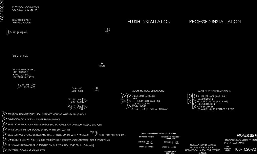
6 OPERATION MANUAL FOR ICP HIGH PRESSURE SENSORS Series 108 & INTRODUCTION The 108 & 109 Series are acceleration-compensated, high pressure, ICP (Integrated Circuit Piezoelectric) sensors primarily developed to measure ballistics chamber pressures for R & D and production testing of ammunition. They may also be used for explosive air blast and other high pressure measurements in extreme shock environments where ultra-fast, microsecond response is required. These types of tests are usually accompanied by large acceleration pulses, which can add considerable error to output signals of un-compensated sensors. The shoulder seal design features a one-piece diaphragm machined integral with the housing for ruggedness. A ceramic coating is applied to the diaphragm to minimize flash temperature effects. For applications where strain sensitivity from stress within the mounting port is a concern, the 108A1X, 108B1X, 109B1X and 109C1X utilize a floating clamp-nut design to reduce the effects, where X denotes pressure range. 2.0 DESCRIPTION COAXIAL CONNECTOR 5/16 HEX 3/8-24 THREAD ICP AMPLIFIER QUARTZ ELEMENT CERAMIC COATING The 108 & 109 Series contain an accelerationcompensated piezo element, which is coupled to a microelectronic amplifier. The quartz element contains an integral seismic mass that counteracts the acceleration effects of the end piece and diaphragm. This compensation acts to extend the frequency characteristics and enhance the transient response of the sensor. The machined diaphragm is made from maraging steel, selected because of its high strength and durability. The combination of the short, rigid element and stiff diaphragm give these sensors a high natural frequency and linearity. The microelectronic amplifier converts the highimpedance voltage from the quartz package into a low-impedance, high-level output signal. See the Technical Information section of our website for more complete coverage of ICP instruments. 3.0 INSTALLATION With a 3/8-24 (M10x1.0 for metric mount) mounting thread and flush diaphragm design, the 108 & 109 Series transducers mount directly in existing ports machined for PCB Series 118 & 119. Unlike conventional diaphragm type sensors, the 108 & 109 Series are pressure sensitive over the entire frontal area. Extra care should be exercised to avoid bottoming in the mounting hole when recess mounted or when mounting into existing ports. Install the sensor, using only one of the seals provided, with the aid of a torque wrench to monitor the mounting torque value. The recommended torque range can be found on the installation drawing. Seals should be replaced each time the sensor is reinstalled. 3.1 MOUNTING IN EXISTING RECESSED PORTS Before installing the sensor in previously used mounting ports, clean out the residue from previous tests. The port can be cleaned by hand reaming the ¼ inch diameter hole using a PCB Model 040A end cutting reamer (040A07 for metric mount) guided by PCB Model 041A pilot bushing (M041A for metric mount). Pay particular attention to the sealing surface, keeping it free from tool chatter marks, nicks and other imperfections that could adversely affect the seal. If the sealing surface requires re-machining after prolonged use, refer to the installation drawing to ensure that the ¼ inch hole is deepened to avoid bottoming of the sensor when re-installed. Drawing Number: Revision: A
7 OPERATION MANUAL FOR ICP HIGH PRESSURE SENSORS Series 108 & MODEL 041A PILOT BUSHING MODEL 040A REAMER The limitation in this type of installation lies in the frequency-limiting effects of the passage due to its length. The passage behaves like an underdamped second order system; the resonant frequency being determined by the passage length. The length may have a limiting effect on pressure pulse rise time and cause passage ringing in cases where the passage is too long. Recessed Mount Existing Recessed Ports If waveform distortion occurs during prolonged testing, remove the sensor and clean the residue as illustrated above. 3.2 PREPARING NEW MOUNTING PORTS Refer to the installation drawing provided in this manual for instructions on mounting hole preparation. For best results, do not deviate from the steps outlined in this drawing. To assist new mounting port preparation, PCB offers the 040B20 Tooling Kit (040B21 for metric mount). These installation kits provide all of the necessary tooling required to drill, ream, and tap the mounting ports for proper installation of the 108, 109, 118 and 119 Series transducers. Use good machining practice in preparation of the mounting port, paying particular attention to the seal surface. It is important that this surface be perfectly smooth and free from tool chatter marks, nicks and other imperfections which might cause leaks at high pressures. 3.3 RECESSED MOUNT The recessed installation is shown in the Recessed Mount figure. This type of mounting protects the sensor diaphragm from the effects of high-flash temperatures and particle impingement due to blast effects, thereby prolonging sensor life. The recommended range of passage diameters is to inch (2.29 to 3.18 mm) diameter MIN The following relationship approximates this resonant frequency (f r): V f r (Hz) (EQ. 1) 4L Where: f r = Resonant frequency of passage (Hz) V = Velocity of sound in air (ft/sec) L = Length of column (ft) For air at room temperature, (EQ. 1) becomes: 3300 f r (EQ. 2) L Where: L = Passage length (in) Drawing Number: Revision: A
8 OPERATION MANUAL FOR ICP HIGH PRESSURE SENSORS Series 108 & The natural frequency and approximate fastest pressure step rise time for various length passages is shown in the following chart. (Medium, air at 25 C). PASSAGE LENGTH (in) PASSAGE RESONANCE (khz) APPROX. FASTEST PULSE RISE TIME ( sec) Passage Resonance vs. Passage Length Actual resonant frequencies measured in practice may differ slightly from the chart values. These differences are due to variations in the velocity of propagation of sound in air caused by changes in temperature and pressure of the air in the passage. For best matching of passage to diaphragm, maintain the inch (0.254 mm) clearance ahead of the diaphragm as shown in the Recessed Mount figure on the previous page. 3.4 FLUSH MOUNT In the flush mount installation, there is no reduced area passage from the sensor diaphragm to the test chamber; rather the sensor diaphragm is mounted flush with (or slightly recessed from) the inside surface of the test chamber. Use this type of installation only if space or rise time considerations preclude the use of recessed installation. In severe pyrotechnic environments, sensor life may be severely limited with flush installation. 3.5 FLASH TEMPERATURE EFFECTS The ceramic coating on the diaphragm of these sensors should render the flash thermal effect insignificant in most cases, especially when recessed mounted. However, if more protection from flash thermal effects is required with the recessed mount, the passage can be filled with silicone grease (DC-4 or equivalent). Several layers of black vinyl electrical tape directly on the diaphragm have proven effective in many cases as well. Flash temperature effects are usually longer term and will show up as a baseline shift long after the event to be measured has passed. For flush mount installations, a silicone rubber coating approximately inch thick can be effective; GE RTV type 106 is recommended, and is available from PCB as Model 065A67. Follow manufacturer s instructions to apply. It is best to recess the diaphragm inch for this type of protection. 3.6 INSTALLING CABLES It is convenient, though not necessary, to use coaxial cable, such as PCB 002 Series, to connect the transducer to the power unit. Cable need not be lownoise treated. If the use of lighter, more flexible cable is desired, PCB Model 070B09 solder connector adaptors may be used to employ twisted pair or other types of twowire cable. Drawing Number: Revision: A
9 OPERATION MANUAL FOR ICP HIGH PRESSURE SENSORS Series 108 & CIRCUIT CONNECTIONS The figures below show two typical circuit connections normally used to connect the 108 & 109 Series to power units. The first figure is the connection scheme used for most applications. In this set up, the signal is ACcoupled from the bias voltage meaning the voltage at the "scope" terminal will be at a zero volt bias level. 002 SERIES 002 SERIES ICP POWER SUPPLY READOUT 108 & 109 SERIES Normal Connection AC-Coupled Output In this case, the system discharge time constant will be determined by the input resistance and capacitance of the power unit. Most PCB power units have approximately a 10 second discharge time constant. Alternate Connection to take Advantage of Sensor Discharge TC The second figure illustrates an optional connection scheme which can be used during calibration to take full advantage of the sensor s discharge time constant. SERIES & 109 SERIES ICP POWER SUPPLY READOUT READOUT ICP POWER SUPPLY With this arrangement, the readout is direct-coupled to the sensor and the output signal will be added to the DC bias voltage (11 VDC nominal). The discharge time constant will then be determined only by the sensor and should be in the order of 2000 seconds; this is sufficient for most types of static calibration methods. (See Calibration Section 4.0) 108 & 109 SERIES Typical Connection The figure above shows the 108 & 109 Series connected to a PCB Model 484B06 power unit. The 484B06 is a power unit that can be AC or DCcoupled. In the DC-couple mode, a level-shifting circuit removes the bias level and provides a zero adjust feature at the front panel. The system s discharge time constant is determined by the sensor in this mode. An AC-coupled mode is provided for normal ACcoupled operation. 4.0 CALIBRATION PCB 108 & 109 Series sensors are supplied with a calibration certification from the factory. Recalibration services are provided at the factory for a nominal fee. Static calibration methods may be employed using the set-up shown in the Alternate Connection figure or by use of the Model 484B06 Power Unit as shown in the figure above use the 484B06 in DC mode. Following thermal stabilization of the sensor, use a high pressure pump with dial reference sensor or a dead weight tester to apply pressure in desired increments to full scale. Release pressure after taking the reading and before proceeding to the next higher pressure level. With a 2000 second discharge time constant, 1% of the signal will be lost in 20 seconds, so it is imperative that the pressure setting and recording of output be accomplished quickly. A calibration graph can be plotted using output voltage vs. input pressure to determine sensitivity and linearity. Drawing Number: Revision: A
10 OPERATION MANUAL FOR ICP HIGH PRESSURE SENSORS Series 108 & OPERATION Select desired mode of circuit connection and turn power unit on. Observe fault monitor meter at the front panel of the power unit. Normal operation is indicated by an approximate midscale reading. Shorted cable or connections are indicated by a zero reading (red area). Open cable or connections are indicated by a fullscale (yellow area) reading. Allow instrument several minutes to warm up and thermally stabilize. When output from the power unit is connected to readout equipment, a drift in the voltage signal will be noticed; this is normal. This voltage signal drift is caused by the charging of the coupling capacitor in the power unit and will cease within several minutes. 6.0 POLARITY The 108 & 109 Series are designed to produce a positive output voltage for increasing pressure at the diaphragm. 7.0 MAINTENANCE The small size and sealed construction of the 108 & 109 Series precludes field maintenance and repair. Contact the factory for further assistance. ICP is a registered trademark of PCB Piezotronics Drawing Number: Revision: A
11
12
Model 137A22. ICP Pressure Sensor. Installation and Operating Manual
 Model 137A22 ICP Pressure Sensor Installation and Operating Manual For assistance with the operation of this product, contact PCB Piezotronics, Inc. Toll-free: 800-828-8840 24-hour SensorLine: 716-684-0001
Model 102B. ICP Pressure Sensor. Installation and Operating Manual
 Model 102B ICP Pressure Sensor Installation and Operating Manual For assistance with the operation of this product, contact PCB Piezotronics, Inc. Toll-free: 800-828-8840 24-hour SensorLine: 716-684-0001
Model 102A05. High resolution ICP pressure sensor, 100 psi, 50 mv/psi, 3/8-24 mtg thd, Installation and Operating Manual
 Model 102A05 High resolution ICP pressure sensor, 100 psi, 50 mv/psi, 3/8-24 mtg thd, Installation and Operating Manual For assistance with the operation of this product, contact PCB Piezotronics, Inc.
Model 123A. Charge Output Pressure Sensor. Installation and Operating Manual
 Model 123A Charge Output Pressure Sensor Installation and Operating Manual For assistance with the operation of this product, contact PCB Piezotronics, Inc. Toll-free: 800-828-8840 24-hour SensorLine:
Model 117B30 CONFORMAL BALLISTICS PRESSURE SENSOR. Installation and Operating Manual
 Model 117B30 CONFORMAL BALLISTICS PRESSURE SENSOR Installation and Operating Manual For assistance with the operation of this product, contact PCB Piezotronics, Inc. Toll-free: 800-828-8840 24-hour SensorLine:
Model 117B30 CONFORMAL BALLISTICS PRESSURE SENSOR. Installation and Operating Manual
 Model 117B30 CONFORMAL BALLISTICS PRESSURE SENSOR Installation and Operating Manual For assistance with the operation of this product, contact PCB Piezotronics, Inc. Toll-free: 800-828-8840 24-hour SensorLine:
D Issue D Original. Instruction Manual. TIC Instrument Controller 6-Gauge. TIC Instrument Controller 6-Gauge Capacitance Manometer
 Instruction Manual D397-01-880 Issue D Original TIC Instrument Controller 6-Gauge Description TIC Instrument Controller 6-Gauge TIC Instrument Controller 6-Gauge Capacitance Manometer Item Number D397-01-000
Sensor Design Parameters for Underwater Applications
 P C B P I E Z O T R O N I C S, I N C. W H I T E P A P E R Sensor Design Parameters for Underwater Applications Bob Metz, PCB Piezotronics, Inc., Depew, NY, USA PCB.com 800.828.8840 SENSOR DESIGN PARAMETERS
Research Grade Blood Pressure Transducer User's Manual
 Research Grade Blood Pressure Transducer User's Manual Research Grade Blood Pressure Transducer, 110 VAC/60 Hz MA1 60-3002 Research Grade Blood Pressure Transducer, 220 VAC/50 Hz MA1 60-3003 WEEE/RoHS
2 Overview. SITRANS P measuring instruments for pressure. Transmitters for gage and absolute pressure. Z series for gage pressure
 Z series for gage pressure Overview Design The main components of the pressure transmitter are: Brass housing with silicon measuring cell and electronics plate Process connection Electrical connection
Type 160 Metallized Polyester Radial Lead Capacitors
 Specifications Type 160 Metallized Polyester Radial Lead Capacitors Radial Box Metallized Polyester Capacitors Capacitance Range: Voltage Range: Capacitance Tolerance: Operating Temperature Range: Dielectric
Liquidyn V200 Controller
 Operating Manual Electronic pdf files of Nordson EFD manuals are also available at www.nordsonefd.com You have selected a reliable, high-quality dispensing system from Nordson EFD, the world leader in
SITRANS P measuring instruments for pressure
 SITRANS P measuring instruments for pressure Z series for gage pressure Siemens AG 008 Overview Design The main components of the pressure transmitter are: Brass housing with silicon measuring cell and
User s Guide Temperature Sensor Converter TSC-599
 User s Guide Temperature Sensor Converter TSC-599 ILX Lightwave Corporation 31950 Frontage Road Bozeman, MT, U.S.A. 59715 U.S. & Canada: 1-800-459-9459 International Inquiries: 406-556-2481 Fax 406-586-9405
P499 Heavy Duty Pressure Transducer
 P499 Heavy Duty Pressure Transducer Product Bulletin Code No. LIT-??? E Issued 11 2006 The P499 Series is a new global Pressure Transducer with an excellent price performance ratio. The P499 exceeds the
AMS 2710 PCB pressure sensor module with V output
 FEATURES Universal pressure sensor module with 0.. 10 V voltage output Fully calibrated and temperature compensated sensor module Variants for (bidirectional) differential, gage, absolute and barometric
Instrumentation & Data Acquisition Systems
 Instrumentation & Data Acquisition Systems Section 4 - Pressure Robert W. Harrison, PE Bob@TheHarrisonHouse.com Made in USA 1 Definition of Pressure Pressure is the amount of force applied perpendicular
PULSAR 5000 SERIES OPERATING & INSTALLATION INSTRUCTIONS SERIES 5000 PLEASE READ CAREFULLY BEFORE INSTALLING
 PULSAR 5000 SERIES OPERATING & INSTALLATION INSTRUCTIONS SERIES 5000 PLEASE READ CAREFULLY BEFORE INSTALLING Please Note: Ranges above 500mbar are designed and manufactured in accordance with sound engineering
Turbine Flowmeters for Gas Applications
 Turbine Flowmeters for Gas Applications Description Flow Technology s FT Series turbine flowmeters utilize a proven flow measurement technology to provide exceptionally reliable digital outputs. Because
Turbine Flowmeters for Gas Applications
 Turbine Flowmeters for Gas Applications Description Flow Technology s FT Series turbine flowmeters utilize a proven flow measurement technology to provide exceptionally reliable digital outputs. Because
BS12N Piezoresistive OEM Pressure Sensor
 BS12N Piezoresistive OEM Pressure Sensor Model: BS12N-1 Model: BS12N-2 Feature Pressure range (-0.1~60)Mpa; Pressure reference: Gauge, absolute and sealed gauge; Constant current power supply; Isolated
The Ins and Outs of I/P Transducers
 The Ins and Outs of I/P Transducers By Mark B. Levine, ControlAir Inc. General description I/P transducers are versatile instruments that use an electrical control signal to proportionally regulate gas
GILMONT ACCUCAL FLOWMETERS
 OPERATING MANUAL GILMONT ACCUCAL FLOWMETERS 28W092 Commercial Ave. Barrington, IL U.S.A. 60010-2392 (847) 381-4888 (847) 381-7053 (Fax) 800-962-7142 www.barnant.com e-mail: barnant@barnant.com A-1299-0766
AMS 6915 Board mount pressure sensor with digital output (I²C)
") Board mount pressure sensor with digital output (I²C) FEATURES Calibrated and temperature compensated pressure sensor with digital output (I²C) Differential, relative (gage), bidirectional differential,
Board mount pressure sensor with digital output (I²C) FEATURES Calibrated and temperature compensated pressure sensor with digital output (I²C) Differential, relative (gage), bidirectional differential,
Gas density monitor With integrated transmitter Model GDM-100-TI
 SF 6 gas solutions Gas density monitor With integrated transmitter Model GDM-100-TI grid Products WIKA data sheet SP 60.05 for further approvals see page 5 Applications Gas density monitoring of closed
DPC-30 DPC-100. Reference Manual
 DPC-30 DPC-100 Reference Manual 1. Introduction 1.1 Description The Martel DPC Digital Pneumatic Calibrator improves upon traditional dial gauge pneumatic calibrators. The Martel DPC improves accuracy,
DX2/DXX Operating Instructions
 CHECK LINE BY ELECTROMATIC DX2/DXX Operating Instructions CHECK LINE INSTRUMENTS ELECTROMATIC E Q U I P M E N T C O., I N C. 600 Oakland Ave., Cedarhurst, NY 11516 U.S.A. TEL: 516-295-4300 FAX: 516-295-4399
TEK-SUB 4800B. Submersible Level Transmitter. Flow Level Temperature Pressure Valves Analyzers Accessories TekValSys LEVEL
 Technology Solutions TEK-SUB 4800B Submersible Level Transmitter LEVEL Flow Level Temperature Pressure Valves Analyzers Accessories TekValSys Introduction The Tek-Sub 4800B Submersible Level Transmitter
TSE Blood Pressure Monitor Invasive series
 TSE Blood Pressure Monitor Invasive 209100series For Invasive Measurements in Laboratory Animals 2 Specifications subject to change without notice USA / Canada / Mexico Phone 1-989-698-3067 Fax 1-989-698-3068
P9000 DESCRIPTION. For parts requiring RoHS compliance, please contact factory. P February /6
 P9000 High accuracy through digital compensation High thermal stability Rugged stainless steel construction Ideal for test stands High burst pressure limit DESCRIPTION The P9000 Series is a range of advanced,
SX150A. Features. Typical Applications. Description
 Datasheet -- Pressure Sensors: Measurement Type: Absolute; 0 psia to 150 psia, Unamplified, Representative photograph, actual product appearance may vary. Due to regional agency approval requirements,
Precision pressure sensor Basic version Model CPT6020
 Calibration Precision pressure sensor Basic version Model CPT6020 WIKA data sheet CT 25.13 Applications Calibration technology High-accuracy pressure monitoring Pressure sensing in critical applications
T EK-SUB 4800C 19 mm Submersible Level Transmitter
 Technology Solutions T EK-SUB 4800C 19 mm Submersible Level Transmitter Instruction Manual Document Number: IM-4800C www.tek-trol.com Table of Contents 1 Safety Instructions... 2 1.1 Intended Use... 2
IDL01. Battery Powered Precision Digital Gauge for Leak Testing. Stainless Steel Sensor. class 0.05
 IDL0 Battery Powered Precision Digital Gauge for Leak Testing Stainless Steel Sensor class 0.05 Nominal pressure from 0 00 mbar up to 0... 00 bar Special characteristics modular sensor concept data logger
MIL-STD-883G METHOD
 STEADY-STATE LIFE 1. PURPOSE. The steady-state life test is performed for the purpose of demonstrating the quality or reliability of devices subjected to the specified conditions over an extended time
3.0 Pressure Transmitter Selection
 3.0 Pressure Transmitter Selection Each Tronic Line pressure transmitter has different features to meet specific performance, environmental, and price requirements. It is not possible to describe every
BAPI Pressure Line of Products - FAQs
 Table of Contents 1. Several manufacturers produce pressure transmitters, why should I purchase from BAPI?... p. 2 2. BAPI makes several styles of pressure transmitters. What are the features of each?...
BS12 Piezoresistive OEM Pressure Sensor
 BS12 Piezoresistive OEM Pressure Sensor Feature Pressure range (-0.1~60)Mpa; Pressure reference: Gauge, absolute and sealed gauge; Constant current power supply; Isolated construction to measure various
High-speed pressure sensor Model CPT6140
 Calibration technology High-speed pressure sensor Model CPT6140 WIKA data sheet CT 25.11 Applications Testing technology Calibration technology Laboratories and maintenance shops Leak and burst applications
FTS SUBMERSIBLE PRESSURE TRANSMITTER USER S MANUAL
 FTS SUBMERSIBLE PRESSURE TRANSMITTER USER S MANUAL TABLE OF CONTENTS PRODUCT OVERVIEW 2 I - USE AND CARE: 3 II - INSTALLATION: 5 III - GENERAL MAINTENANCE TIPS: 5 IV - APPENDIX: A-1 2-WIRE CURRENT LOOP
Cover Page for Lab Report Group Portion. Pump Performance
 Cover Page for Lab Report Group Portion Pump Performance Prepared by Professor J. M. Cimbala, Penn State University Latest revision: 02 March 2012 Name 1: Name 2: Name 3: [Name 4: ] Date: Section number:
PURA. Pure Gas Dewpoint Transmitter. Users Guide
 PURA Pure Gas Dewpoint Transmitter Users Guide Issue January 2003 Page 2 Table of Contents SECTION PAGE 1 Product Overview 3 2 Preparation 3 3 Installation 3 3.1 PURA Premium & OEM Dewpoint Transmitter
Pressure Measurement
 Pressure Measurement Manometers Sensors, Transducers Ashish J. Modi Lecturer, Dept. of Mech.Engg., Shri S.V.M. inst. Of Technology, Bharuch Pressure Pressure is a force per unit area exerted by a fluid
EASIDEW TRANSMITTER with Current Source Output
 EASIDEW TRANSMITTER with Current Source Output INSTALLATION, OPERATION AND MAINTENANCE MANUAL Issue March 2002 2 TABLE OF CONTENTS SECTION PAGE 1. INTRODUCTION 3 1.1 General 3 1.2 Ceramic Sensing Element
ACV-10 Automatic Control Valve
 ACV-10 Automatic Control Valve Installation, Operation & Maintenance General: The Archer Instruments ACV-10 is a precision automatic feed rate control valve for use in vacuum systems feeding Chlorine,
High-performance submersible pressure transmitter For level measurement Model LH-10
 Electronic pressure measurement High-performance submersible pressure transmitter For level measurement Model LH-10 WIKA data sheet PE 81.09 Applications Level measurement in rivers and lakes Deep well
Deep Submersible Level Transducer Series 300DS
 KPSI Transducers Deep Submersible Level Transducer Series 300DS FEATURES! Custom Level Ranges up to 4614 ft (1408 m) H 2 O! Accuracy of ±0.5% FS! Analog Outputs of 4-20 ma or 0-5 VDC! Welded 316 SS Construction!
Operating Instructions Melt Pressure Sensor
 Operating Instructions Melt Pressure Sensor DA Certified to ISO 9001:2008 Please read this instruction manual carefully before installing the transducer 1 Contents: 1. Introduction 2. Operating range and
PROPORTIONING VALVE. Model 150 INSTRUCTION MANUAL. March 2017 IMS Company Stafford Road
 PROPORTIONING VALVE Model 150 INSTRUCTION MANUAL March 2017 IMS Company 10373 Stafford Road Telephone: (440) 543-1615 Fax: (440) 543-1069 Email: sales@imscompany.com 1 Introduction IMS Company reserves
AN ANALYSIS ON HIGH PRESSURE DYNAMIC CALIBRATORS USED IN THE DEFENSE AREAS
 AN ANALYSIS ON HIGH PRESSURE DYNAMIC CALIBRATORS USED IN THE DEFENSE AREAS Sung Soo HongPresenter Agency for Defense Development, Taean, 357-942, South Korea sungsoo@add.re.kr Abstract Up to now, there
Module 2, Add on Lesson Depth Sensor. Teacher. 90 minutes
 Module 2, Add on Lesson Depth Sensor 90 minutes Teacher Purpose of this lesson Investigate the relationship between pressure and depth Construct a sensor to measure the depth of water Graph data and reason
P900. P900, Datenblatt Seite 1 DESCRIPTION
 , Datenblatt Seite 1 Field proven rugged construction High overpressure capability High reliability for demanding environments Application specific customization Excellent media compatibility Shock and
CDS-2000 CO 2 Sensor Verification, Calibration, and Troubleshooting Bulletin
 Electronic Control Manual 216 Sensors and Stats Section S Technical Bulletin CDS-2000 Issue Date 0393 CDS-2000 CO 2 Sensor Verification, Calibration, and Troubleshooting Bulletin Introduction 3 Pre-Verification
Pressure Transmitters 36 F-27839
 Pressure Transmitters 36 F-27839 SPD310/SPD360 Air Differential schneider-electric.com 37 SPD310/SPD360 SPD310/SPD360 differential pressure transmitters are intended for use in air handling systems for
_ pressure transducers. User Manual
 _ pressure transducers User Manual summary introduction DescriPTION preliminary checks Installation taking measurements data management Troubleshooting maintenance Appendix 1 Page 4 Page 5 Page 6 Page
Doppler Volume Sampler (DVS TM ) Operation Manual
 Operation Manual") Doppler Volume Sampler (DVS TM ) Operation Manual P/N 95B-6035-00 (January 2009) 2009 Teledyne RD Instruments, Inc. All rights reserved. Information included herein is controlled by the Export Administration
Doppler Volume Sampler (DVS TM ) Operation Manual P/N 95B-6035-00 (January 2009) 2009 Teledyne RD Instruments, Inc. All rights reserved. Information included herein is controlled by the Export Administration
AMS 6916 Board mount pressure sensor with ratiometric analog output
 FEATURES Piezoresistive pressure sensor with amplified analog output Calibrated and temperature compensated Ratiometric voltage output, 0.5 4.5 V Digital signal conditioning, 12 bit output resolution Differential,
Pressure transmitters EMP 2
 Data sheet Pressure transmitters EMP 2 The high accuracy pressure transmitter EMP 2 is designed for monitoring and control in marine and industial applications and offers a reliable pressure measurement,
ASDX Series Silicon Pressure Sensors
 ASDX Series Silicon Pressure Sensors DESCRIPTION The ASDX Series is a Silicon Pressure Sensor offering a ratiometric analog interface for reading pressure over the specified full scale pressure span and
LUDLUM MODEL 239-1F FLOOR MONITOR. Revised December 2010
 LUDLUM MODEL 239-1F FLOOR MONITOR Revised LUDLUM MEASUREMENTS, INC. 501 OAK ST., P.O. BOX 810 SWEETWATER, TX 79556 325/235-5494 FAX: 325/235-4672 STATEMENT OF WARRANTY Ludlum Measurements, Inc. warrants
DM01. Please visit our website: Battery Powered Precision Digital Gauge. Stainless Steel Sensor. class 0.05
 DM0 Battery Powered Stainless Steel Sensor class 0.05 Nominal pressure from 0 00 mbar up to 0... 00 bar Special characteristics modular sensor concept data logger graphic display stainless steel housing
L 100. Bubble-Tube Level System. Installation, Operation and Maintenance Instructions
 L 100 Bubble-Tube Level System Installation, Operation and Maintenance Instructions Figure 1 Contents Section Description Page 1.0 Introduction 2 2.0 Specifications 3 3.0 Installation 3 4.0 Warranty 6
ETd 04. Battery Powered Precision Digital Gauge. Stainless Steel Sensor. Type: ETd 04. class 0.05
 Battery Powered Stainless Steel Sensor class 0.05 Nominal pressure from 0 100 mbar up to 0... 400 bar Special characteristics modular sensor concept data logger graphic display stainless steel housing
Coriolis Mass Flow Meter
 Coriolis Mass Flow Meter TMFW Series Mini Type Coriolis Mass Flow Meter Xi an Tosilon Automation Co., Ltd No.299, Daqing Rd, Lianhu District, Xi'an Shaanxi, China Tel: +86-29-8823 8550 info@tosilon.com;
Installation, Operation and Maintenance Instructions for Electronically Controlled Pressurisation Units
 Installation, Operation and Maintenance Instructions for Electronically Controlled Pressurisation Units Models: EPS Single Pump EPT Twin Pump EPS-HP EPT-HP Single Pump High Pressure Twin Pump High Pressure
DTG - LCD Digital Temperature Gauge USER MANUAL
 DTG - LCD USER MANUAL Page 1 of 7 USERS GUIDE page 1. Description 3 2. Function 3 3. Safety Instruction 3 3.1. Safety Conventions 3 3.2. Proper Use 3 4. Installation 4 4.1. Unpacking 4 4.2. Storage 4 4.3.
L (up to 25 m) Electronic part. working temp.: Ñ IP 66 / IP67. Mounting bracket ÐÑ. Sensor type. working temp.:
 Electronic part. working temp.: Ñ IP 66 / IP67. Mounting bracket ÐÑ. Sensor type. working temp.:") Smart level probe type APC-2000ALW/L Programmable zero shift, range and damping ratio 4...20 ma output signal + HART protocol Accuracy 0,16% Local display Intrinsic safety certificate (ATEX, IECEx) II
Smart level probe type APC-2000ALW/L Programmable zero shift, range and damping ratio 4...20 ma output signal + HART protocol Accuracy 0,16% Local display Intrinsic safety certificate (ATEX, IECEx) II
Turbine Flowmeters for Gas Applications (Metric)
") Turbine Flowmeters for Gas pplications (Metric) Description Flow Technology s FT Series turbine flowmeters utilize a proven flow measurement technology to provide exceptionally reliable digital outputs.
Turbine Flowmeters for Gas pplications (Metric) Description Flow Technology s FT Series turbine flowmeters utilize a proven flow measurement technology to provide exceptionally reliable digital outputs.
INSTALLATION & MAINTENANCE INSTRUCTIONS
 DESCRIPTION / IDENTIFICATION The QBX series valve uses Proportion-Air closed loop technology for Pressure control. It gives an output pressure proportional to an electrical command signal input. The QB1X
Type N-10, N-11 Hazardous Area Non-incendive Transmitters
 Electronic Pressure Catalog > Hazardous Area > N-10, N-11 Type N-10, N-11 Hazardous Area Non-incendive Transmitters Applications Natural gas compressors Wellhead monitoring Pipeline pressure General industrial
Flexible Metal Hose Products
 Flexible Metal Hose Products Specialty Flexible Hose Solutions of Stainless Steel The AEROCOM Advantage Aerocom offers engineered solutions that address specific flexible piping challenges such as vibration,
Sensoric 4-20 ma Transmitter Board Operation Manual
 Sensoric 4-20 ma Transmitter Board Operation Manual 1 Content Features Operation Manual Technical Data Mechanical Dimensions Remarks & Contact information 2 Features Soldered sensor cell (non replaceable)
Design Features. General Description
 Model thermal Mass Flow Controllers are designed to indicate and control set flow rates of gases. The combines the characteristics and accuracy of conventional mass flow devices into a unique compact design
Fraction Collector Frac-920 and Frac-950
 Fraction Collector Frac-920 and Frac-950 Operating Instructions Original instructions Table of Contents Table of Contents 1 Introduction... 1.1 Important user information... 1.2 Regulatory information...
High-performance submersible pressure transmitter For level measurement Model LH-10
 Electronic pressure measurement High-performance submersible pressure transmitter For level measurement Model LH-10 WIKA data sheet PE 81.09 Applications Level measurement in rivers and lakes Deep well
GEMS SENSORS & CONTROLS
 GEMS SENSORS & CONTROLS OPERATING & INSTALLATION INSTRUCTIONS 31XX / 32XX SERIES PLEASE READ CAREFULLY BEFORE INSTALLING Part Number: 560550-0076 Issue: E INTRODUCTION Series 3100/3200 high output pressure
Flow Meters and Flow Controllers
 Flow Meters and Flow Controllers HFM-205 Flow Meter HFC-207 Flow Controller HIGH CAPACITY FLOW METERS AND FLOW CONTROLLERS FEATURES ± 1% full scale accuracy 1 Input Power: +/- 15 VDC or +24 VDC (specify
In the USA, call between 8:00 a.m. and 5:30 p.m. Eastern time.
 Introduction You have selected a reliable, high quality Performus dispensing system from Nordson EFD, the world leader in fluid dispensing. The Performus dispensing system was designed specifically for
INSTALLATION AND OPERATING INSTRUCTIONS
 INSTALLATION AND OPERATING INSTRUCTIONS For 3D Instruments Direct Drive Pressure Gauges 3D Instruments Inc., 15542 Chemical Lane, Huntington Beach, CA, 92649, U.S.A. Tel. (714) 894-5351, Fax. (714) 895-4309
DM01. Battery Powered Precision Digital Gauge. Stainless Steel Sensor. class 0.05
 Battery Powered Stainless Steel Sensor class 0.05 Nominal pressure from 0 00 mbar up to 0... 00 bar Special characteristics modular sensor concept data logger graphic display stainless steel housing Ø
Pressure Measurement. Transmitters for basic requirements SITRANS P Z for gauge pressure. 2/4 Siemens FI Overview
 f gauge pressure Siemens AG 010 Overview Design The main components of the pressure transmitter are: Brass housing with silicon measuring cell and electronics plate Process connection Electrical connection
PM105 PRESSURE METER USER S MANUAL
 PM105 PRESSURE METER USER S MANUAL Manual revision: 15 March, 2001 SCSMANP015 Copyrighted 2001 Thank you for purchasing a Tek Know pressure meter. The Tek Know products are manufactured by Scan-Sense AS
Next Generation Quartz Pressure Gauges
 Next Generation Quartz Pressure Gauges Rick Puccio, Ph.D. Senior Scientist Quartzdyne Houston, TX March 2, 2016 Outline Quartz Pressure Gauge Introduction Gauge Size Reduction Long Term Pressure Drift
Installation and Operation Manual
 Manual Static pressure transducer with controller Differential static pressure transducer with analog output and optional PI control mode Large diaphragm element with differential transformer Transducer
Cover Page for Lab Report Group Portion. Head Losses in Pipes
 Cover Page for Lab Report Group Portion Head Losses in Pipes Prepared by Professor J. M. Cimbala, Penn State University Latest revision: 02 February 2012 Name 1: Name 2: Name 3: [Name 4: ] Date: Section
Hidrostatic Level DATASHEET
 Hidrostatic Level DATASHEET JUNHO 2013 Hydrostatic level probes SGE-25 and SGE-16 SG cable hanger Red (+) Capillary Black ( ) PP junction box Any measurement range from 1 up to 500 m H 2 O Integrated internal
INSTRUCTION MANUAL MP4AR Remote Convection Gauge Range: 1 x 10⁻³ Torr to 1 x 10+3 Torr
 INSTRUCTION MANUAL MP4AR Remote Convection Gauge Range: 1 x 10⁻³ Torr to 1 x 10+3 Torr A DIVISION OF THE FREDERICKS COMPANY 2400 PHILMONT AVE. HUNTINGDONVALLEY, PA 19006 PARTS LIST 1 3 4 2 # QTY ITEM DESCRIPTION
Assembly Drawing: W-311B-A01, or as applicable Parts List: W-311B-A01-1, or as applicable Special Tools: , , &
 REDQ Regulators Model 411B Barstock Design Powreactor Dome Regulator OPERATION AND MAINTENANCE Contents Scope..............................1 Installation..........................1 General Description....................1
EcoPRO-Series 4-20mA SUBMERSIBLE PRESSURE TRANSMITTER INSTRUCTIONS
 EcoPRO-Series 4-20mA SUBMERSIBLE PRESSURE TRANSMITTER INSTRUCTIONS EcoPRO-Series 4-20mA SUBMERSIBLE PRESSURE TRANSMITTER INSTRUCTIONS 9001:2008 ISO CERTIFIED COMPANY Table of Contents Introduction - EcoPRO-Series
UBEC 1AT. AUTO TANK Fill System Installation, Operation, & Setup Instructions
 Document Number: XE-ATA5PM-R1A UBEC 1AT AUTO TANK Fill System 08899155 Installation, Operation, & Setup Instructions Rev170906-EB-FRC PHYSICAL: 1302 WEST BEARDSLEY AVE ELKHART, IN 46514 WWW.ELKHARTBRASS.COM
GFM. Typical Aluminum GFM Mass Flow Meter NIST MASS FLOW METERS. Principles of Operation. Design Features
 Design Features Rigid metallic construction. Maximum pressure of 1000 psig (70 bars). Leak integrity 1 x 10⁻⁷ of helium. NIST traceable certification. Built-in tiltable LCD readout. 0-5 Vdc and 4-20 ma
* * Data Sheet and Operating Manual. Digital manometer ME01 ## # 87 # HL S#### Dust explosion protection Zone 22.
 *09005087* DB_BA_EN_ME01_S Rev.A 12/16 *09005087* d e v e l o p i n g s o l u t i o n s Data Sheet and Operating Manual ME01 Digital manometer Table of Contents ME01 ## # 87 # HL S#### Dust explosion protection
Pressure Measurements
 ME 22.302 Mechanical Lab I Pressure Measurements Dr. Peter Avitabile University of Massachusetts Lowell Pressure - 122601-1 Copyright 2001 A transducer is a device that converts some mechanical quantity
E2K-L. Liquid Level Sensor That Is Unaffected by the Color of the Pipe or Liquid. Liquid Level Sensor. Ordering Information
 Liquid Level EK-L CSM_EK-L_DS_E 3 Liquid Level That Is Unaffected by the Color of the or Liquid Mount to bypass pipes. Fit a wide range of pipe diameters: 8 to mm or to mm Built-in Amplifiers to save space.
Auto-Zero Calibration Technique for Pressure Sensors
 Auto-Zero Calibration Technique for Pressure Sensors A Technical Note 1.0 INTRODUCTION This technical note describes how to implement Auto-Zero, a calibration technique for pressure sensors based on sampling
M iniature Amplified Pressure Sensors
 M iniature Amplified Pressure Sensors ±0.3 psi to 100 psi Pressure Sensors Features 0 to ±0.3 to 0 to 30 psi Pressure Ranges Ratiometric 4V Output Temperature Compensated Calibrated Zero and Span General
SPECIFICATIONS ATTENTION
 VPS 504 S06 Installation Manual - P/N 80122 - Ed. 01/09 VPS 504 S06 and S05 Valve Proving System Installation Instructions VPS 1 6 Gases Natural gas, air and other inert gases. NOT suitable for butane
Differential Pressure Transmiter
 Differential Pressure Transmiter Description The is an economical alternative to established differential pressure transmitters. It combines state of the art electronics and a high performance sensor;
Advanced Test Equipment Rentals ATEC (2832)
") WARRANTY CLAUSE METROSONICS warrants each new cl-304 manufactured and sold to be free from defects in material, workmanship and construction, except for batteries which may be contained therein, and that
WARRANTY CLAUSE METROSONICS warrants each new cl-304 manufactured and sold to be free from defects in material, workmanship and construction, except for batteries which may be contained therein, and that
Float Equipment TYPE 925/926
 Type 925 Float Collar Plunger Valve Float Equipment For less demanding well conditions, such as shallower depths or lower pressures, Top- Co offers economical float equipment certified to API RP 10F category