JOHN WRIGHT COMPANY BLOWOUT CONTROL ENGINEERING AND RELIEF WELL SPECIALISTS SINCE 1989
|
|
|
- Augustus Carr
- 5 years ago
- Views:
Transcription


1 JOHN WRIGHT COMPANY BLOWOUT CONTROL ENGINEERING AND RELIEF WELL SPECIALISTS SINCE 1989 Highlights First bridge plug placed in a blowout from a relief well Relief well used to safeguard the environment on well knocked over by shrimp boat HPHT Blowout logged and production tested after a 7 liner set in a re-entered 8-1/2 open hole from a relief well below 3800m Connect wells between two platforms to eliminate a subsea pipeline Unique relief well technology used to safeguard a platform from blowout risk Inside this issue: Projects since 2000 Blowout Hazard Management Why Well Flow Dynamics? Capping on Fire and Engineering Gas Storage Field Blowout Control with Relief Well Relief Well used to Safeguard the Environment Gunk and Relief Well used to Salvage HPHT well Study Shows Wells can be Connected End to End Relief Well used to Protect a Platform from Blowout Risk Innovation and Experience World Leaders in Relief Well Design & Implementation Need a relief well construction partner with the capabilities to get you there? A well oiled, high performance relief well drilling machine. This is the kind of integrated engineering team we have built since We have successfully designed and implemented over 30 diverse relief well and intersection projects worldwide. A number that cannot be approached by any other company. We have the total project management experience, processes, technology, mobility, and local understanding of client s needs worldwide. And key team members that have been with us since the beginning. When it comes to capabilities we have the whole performance package. We develop the strategy, design the kill and intersection using proprietary process steps and software tools, integrate the design into the clients management team, coordinate service companies, subcontract special services and supervise the implementation. We provide you more options to accelerate your project completion and free your key employees to manage other aspects of your business. You get the confidence that you have the best team and technology in the world. Call John Wright Company and be assured of getting there, on time and within budget. How Critical are Hydraulic Simulations? Some companies claim they are of minimal importance, we ve gotten by for donkey years without it and besides there are too many unknowns. Analysis: they do not understand the problem, do not have the software & expertise, or it is not in their interest. Hydraulic modeling drives every aspect of blowout control. From kick tolerance and kick circulation for prevention to blowout modeling for flowpath diagnostics, multiple flow zones, pollution, gas dispersion, temperature effects, hole collapse, erosion potential, gas lifted water, crossflow, depletion, capping design, diverter design, snubbing design and more. Kill simulations control fluid requirements (density & volume), temperature and pressure effects, pumping plant requirements, tubular requirements for relief wells and snubbing kills, rig requirements, personnel, support equipment, barges, etc. If you have a complicated blowout hip-shooting diagnostics and kill attempts can lead to disaster. Complicated control operations require experience, state of the Continue Slot w/rotary m Top m 6.6m (22 ft) Bottom m art software tools, systematic diagnostics and an integrated engineering solution. Since 1991, Well Flow Dynamics is the only company dedicated fulltime to simulating kicks, blowouts and hydraulic kills. We have the most advanced software using OLGA 2000 in conjunction with proprietary blowout well and kill modules. Our flow engineers will work independent of your choice of contractors to assure you have the best unbiased engineering knowledge available to base your multimillion dollar decisions.


2 Page 2 John Wright Company Well Control and Blowout Prevention Services "Learn from the mistakes of others. You can never live long enough to make them all yourself. It Can t Happen Here Organizations don t have memories. Only people have memories and they move on. Trevor Kletz Accidents re-occur every 10 to 15 years Victory awaits those who have everything in order people call that luck. Defeat awaits those who don t this they call bad luck. Amundsen A Blowout Hazard Management System Many blowouts occur because those concerned did not know how to prevent them although the knowledge may be well known to other people. The knowledge was in the wrong place! Because personnel are constantly on the move knowledge is lost to the organization. A systematic process can help to minimize this loss. In 1994 John Wright Company (JWC) implemented the first blowout contingency plans utilizing a hazard management process. These processes were developed in the petrochemical industry and were adapted for blowouts. There are 4 essential parts to managing hazards: 1. Identify the Hazards 2. Define the impact and probability of hazard release and escalation 3. Implement controls to reduce the risk and mitigate escalation of an event An Ounce of Prevention is Worth a Pound of Cure Hazard identification is best performed using a team of engineers and operation personnel familiar with the design, equipment and procedures for the well construction or workover and blowout control engineers from JWC. We evaluate the well construction program and list any obvious hazards. Next static and circulation kick tolerances are calculated based on the design. We look for probability of underground crossflow either from kick or swabbed influx. If cross flow is possible we evaluate blowout rates, flowing borehole pressures, probability of collapse, and possibility of escalation to a surface or seabed blowout. We next evaluate surface and/ or subsea blowout rates for plausible scenarios. We calculate flowrates, oil/gas/water ratios, temperature profile, velocity profile, and pressure profile. Sensitivities are then run to determine critical variables (e.g.., IPR, reservoir pressures, fluid composition, exit pressure, hole diameter, kh, etc.). This information is used to evaluate impact on environment and people. Oil rates may provide input to pollution models and gas rates to gas dispersion models for ignition and H 2 S poison gas risk. We next evaluate kill rates. If sustained crossflow is possible we calculate whether it is possible to control the crossflow using the existing rig. If not, what is required? Perforate the HWDP, more HHP, snub larger tubulars, reactive gunks or a relief well or combination. For surface blowouts we evaluate kill rates required at defined points in the well. The normal presentation is a chart showing kill rate verses a variable (e.g., kh) with a number of curves using different mud densities. These curves can be generated for any number of sensitivities and are useful to bound realistic scenarios for exploration wells where many parameters are speculation. The next phase is to connect the kill point with a conduit to 4. Develop a plan to respond if an event occurs for three levels of severity. Level 1 - An SOP exists for recovery (e.g. kick) Level 11 - No SOP exists for recovery, but a complicated situation exists which could escalate to a blowout if mishandled Level A blowout. ICS system or similar recommended for recovery the surface. This may be a snubbed in drillstring or it may be a relief well. We then compute injection pressure, HHP, and volumes for various tubular configurations until a reasonable compromise is achieved between kill depth, HHP, kill fluid density and volume. For critical wells (e.g., HPHT, deepwater, remote) we produce a complete plan to include relief well and surface planning to uncover any scenario that may prove difficult to implement a control plan. Management can then decide, based on the risk, if changes are justified to the plan or if extra training or mitigation steps are necessary or if additional insurance may be justified. Response plans cover actions at the wellsite and at the office for kicks, complicated non-sop recovery and for a blowout which includes a 48 hour plan and procedures to accelerate the management of regaining control of the well.

3 Innovation and Experience Page 3 Why Well Flow Dynamics? State of the art software, dedicated specialists and 15 years c o n t i n u o u s e x p e r i e n c e. Dr. Rygg worked as a flow scientist on the OLGA project for IFE in the late 1980s. He developed kill and well modules for this software at the request of Saga Petroleum after a North Sea blowout. In 1991 we obtained licenses for OLGA and formed Well Flow Dynamics (WFD) to offer blowout and kill simulation services to the industry, Dr. Rygg is the director. Since that time three additional engineers have What can we simulate? Fully transient three phase model, gas, oil and water/ mud simulations State of the art PVT model for oil/gas/water Support for non-newtonian fluid flow with drilling fluids including PVT effects on muds Different rheology models, Herchel-Buckley, Power Law and Bingham Detailed reservoir inflow description, e.g. permeability, net pay Different IPR relations, eg. Forchheimer, Vogels, Back- joined the firm all with masters degrees in flow dynamics and petroleum engineering. WFD maintains the latest version of OLGA 2000 as new releases are made by Scandpower. Our blowout and kill modules, that interface with OLGA2000, are proprietary inhouse software packages that have been under continuous development since Performing complicated blowout diagnostics, simulating blowouts under various sensitivities and developing a kill pressure Complex well bore geometry, e.g. flow through bit nozzles, annular flow, tool joints, wellheads Capable of simulating fracturing resulting in losses and injection Kick tolerance and kick circulation simulations Simulation of fluid flow in drilling operations Start-up and shutdown of production & well testing Production from different zones & gas lifted water program is not a job for an engineer who only occasionally uses a simple model and has no formal training in the science of multiphase flow in wells and reservoirs. WFD is the only company that is dedicated to this highly specialized field. Independent and unbiased diagnostics of your blowout and kill hydraulic requirements just makes good business sense. Call the Professionals. Reservoir injection, WAG Cross flow analysis Multilateral well simulations Underbalanced drilling Blowout simulations Any number of ingoing and outgoing branches Process equipment: chokes & separators Advanced controllers Positive displacement pump model Rapid evaluation of sensitivities on simulations Well Flow Dynamics forms exclusive agreement with Scandpower for OGLA2000 use to simulate blowout kills OLGA 2000 is the world leading software suite for transient multiphase flow simulations Blowout and Kill Hydraulic Simulation Special Services WellFlow Software Wellflow is an easy-to-use simulator that calculates pressures, temperatures, flowrates, liquid holdup and velocities in a wellbore. The software is specially designed to help as a diagnostic tool for uncontrolled well situations or to be used in contingency planning for new wells. Different inflow correlations can be used and are calculated by using reservoir properties. The blowout simulations will give the rate of gas and oil together with the pressure profile in the well. Both internal and annulus flow are supported. A pseudo transient kill module will give an estimate of the required kill rate. The module includes the effect of slip between the reservoir fluid and the kill fluid. The built in black oil utility will generate thermodynamic properties for the reservoir fluid based on well known correlations from the literature. In addition the user can import fluid property tables from 3rd party characterization software packages if a more detailed description is required. This software is for sale to selected Well Flow Dynamics clients. Contact us for details. SINTEF Large Scale Flow Loop in Norway Over 10,000 Experiments OLGA flow correlations $70 Million in development


4 Page 4 John Wright Company Surface Blowout Engineering and Kill Design Prolific Gas Blowout Initiated during a Workover Operation It was critical that minimum pressure be exerted on the wellhead after capping and during snubbing to avoid an underground blowout Capping on Fire - What we do as Engineers This prolific gas well blew out in early The well was cased with no chance of bridging in a giant gas field. A relief well was expected to take more than a year. It was critical that the well be capped successfully. The primary identified risk was casing burst after capping due to sand erosion near the surface. Blowout engineers were requested by the operator. John Wright and Ole Rygg were mobilized. Our primary job was to work with the operator s engineering team in developing a control strategy after the well was ready to be capped. Our secondary role was to support the capping team as requested. The major steps in that process are as follows: Access the blowout boundary conditions; Define kill methods to evaluate (cap well and bullhead, cap well - divert - snub in tubing and circulation kill or drill a relief well); Perform kill analysis for chosen method; Define pros and cons for each method; Re-evaluate kill methods at capping milestones. Accessing the boundary conditions required: Compiling data on the blowout; Tune simulator to match production data by varying IPR and pipe 20 0 roughness; Develop Production data before workover 14 m pay & 1000 md, Skin: base case IPR 14 m pay & 1760 md, Skin: 21 curve; Develop sensitivities for high & low case IPR from reservoir kh and skin values; Develop tubing performance curves for various blowout configuration and pipe roughness. Design Diverter and Snubbing Loads After determining the base case IPR curve for the gas blowout, the next task was to consider diverter arrangements that would minimize wellhead pressure after capping. Pressure drop simulations were performed for different configurations. Two opposing diverter lines were chosen for the design, a 10 and 8 line of 250m length each. Snubbing pipe sizes of 4-1/2 and 5 were evaluated. 5 would have the largest initial pressure drop but would reduce as the pipe was snubbed into the well due to higher friction pressure. The 5 would also reduce the required kill rate for the same reason. Pressure (bar) Estimated Lowest Flowrate; 4.1 MM Cu rrent estim ated flow w ith fish ch o ke Flow rate (mill. Sm³/d) Tubing cu rve, Open flow rough pipe Tubing curve, Open flow smooth pipe 14 m pay & 1760 md, Skin: 0 14 m pay & 2000 md, Skin: 0 Base Case Flowrate 5.8 MM Estimated Highest Flowrate 7.5 MM When the wellhead was severed, 560 m of BHA was dropped back into the well. It was not certain if this string fell to bottom or was caught at the top of the 7 liner. If the pipe was caught the kill would be more difficult as the snubbed pipe could only reach the top of the fish some 1000m off Flowrate versus wellhead pressure bottom. Case The kill plant would have to be designed assuming this to be the case. After the well was capped and the diverter lines installed, pressure readings in the lines and wellhead were used to refine the original flow calculations to 5.6 Mm 3 Flow through both Southeast /d. Simulations additionally indicated the fish Case 5C and Northwest Diverter 10" Flow vs. WHP 5 73 No pipe snubbed in was indeed caught at the liner top The 5 was chosen as the snubbed Flowrate Gas, mill Sm³/d pipe diameter after this assessment. Pressure, bar Pressure, psi Kill Plant Design and Implementation Tubing was snubbed in the well for a controlled circulation kill The kill plant was designed based on the worst case scenario. This required 40 bpm of 1.6 sg mud with a total volume requirement w/50% excess of 4000 bbls. Pumping units assessed for flowrate and HHP with one unit backup. A total of five HT2000 pumps were assembled. A mud plant was constructed consisting of bbl tanks in four banks with a mixing tank in each bank. A 100 bpm blender was used to feed the high pressure pumps from the mud plant. 2 x 5 liner of 320 m in length connected the discharge side of the pumps to the tubing on the snubbing unit. A choke manifold was installed to BOP and after the kill fluid was seen at the flairs, the diverters would be closed on the kill continue through the manifold. After the kill plant was installed and tested the 5 tubing was snubbed into the well following exactly the pressure profile predicted by OLGA. The fish was tagged as predicted at the top of the liner and fell to the bottom of the well. The pipe was snubbed to the top of the fish and the kill completed as planned. The client was sufficiently impressed with the operation and the accuracy of the software that we were asked to develop a steady state blowout modeling package their engineers could use. This is the Wellflow model seen on page 3.

 as the flow broached to the surface.")


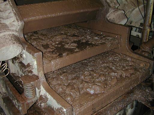
5 Innovation and Experience Page 5 Gas Storage Field Blowout Requires a Relief Well Control of a gas storage well was lost during a workover operation in August The gas quickly ignited destroying the rig and associated equipment. The well was efficiently capped by the national control team but the casing burst below ground when the well was shut-in and bullheaded. An adjacent well disappeared below the ground (see picture top right) as the flow broached to the surface. The capping BOPs were opened stopping the broach but the well subsequently cratered and began making large volumes of produced water. A relief well was the only practical solution to regain control. Project Planning Considerations The flowing reservoir was an unconsolidated sand package. Sand production observed at the surface provided evidence of potential erosion of the casing around the perforations and possible creation of a cavern. Other normal pressure sands were located just above the flow zone. In evaluating the intersection point options, an obvious choice would be to drill straight to the perforations. Hydraulic simulations, however, indicated it could be much more difficult to kill the well if the normally pressured sands connected to the An immediate requirement was the necessity to store the produced water and prevent run-off into local drainage ditches. The well was located in a prolific agricultural area. A sump pit was dug followed by four 40,000m 3 surface pits lined with plastic. Large submersible pumps moved the water from the sump pit to the storage pits. Disposal of produced water can be one of the most expensive aspects of a land blowout control operation but is rarely considered in risk assessments. The relief well design method used on this project was developed by John Wright Company and refined blowout flow path during the drilling of the relief well. The sands were separated by only a thin shale and would be very risky to attempt to set the kill casing in this shale. Based on this analysis a kill point was evaluated 300m above the gas sands. This option would require a more complicated intersection and hydraulic communication but reduced the risk of complications associated with a perforation intersection. Following the design method the relief well surface location was on over 30 relief well projects. The relief well strategic planning process is based on an iterative procedure. For additional details see our website: chosen at 250 m upwind from the crater. The only rig immediately available was a dated mechanical unit with a kelly and duplex pumps. The intersection depth was chosen in a shale at +/- 950 m. The relief well casing would be 9-5/8 with a short 7 liner. It would be positioned with a low incident angle pointed at the intersection target. Hydraulic communication would be achieved using a mill. After the well was killed, a slot would be milled and an attempt made to reenter the casing and if possible a bridge plug would set. A WORLD FIRST A cast iron bridge plug is set inside the blowout casing 200 m below a slot milled from the relief well Top m 6.6m (22 ft) Continue Slot w/rotary Relief Well Design and Implementation m Project Implementation Bottom m JWC supervised all special services for this project, which include everything not normally associated with drilling a gas well. Vector Magnetics were contracted to provide homing-in services. The blowout well was vertical but there were no surveys taken in the top 500 m. The intersection angle was less than 3. This required precision direction drilling at very low inclinations all within a few feet from the blowout casing. SDI, high speed Keeper gyro was utilized to take drillpipe surveys during drilling. To avoid accidental intersection with the blowout casing prior to setting a kill string in the relief well, 9-5/8 was set 2 m laterally away. Then rock bits were used to steer to the intersection depth. Once this was achieved a short 7 liner was set. The kill plant was assembled using local pump trucks and connected to the well with imported high pressure lines. A HES supervisor with an electronic flow monitoring kit assisted in plant design and kill monitoring. Hydraulic communication was gained using a custom designed mill on the end of a mud motor. A hole was cut in only a few seconds. After the flow was stopped, the well went on a vacuum due to depletion during the blowout. With produced water pumped down the annulus a 7 m slot was extended down the casing. The casing was re-entered and the window dressed with string mills. After a test run was made, a bridge plug was hydraulically set just above the perforations. This was followed by a balanced cement plug back to the window, and finally a retainer cement job to the blowout surface. Good plan, good team and success beyond expectations.


6 Page 6 John Wright Company Relief Well Used to Safeguard Environment in GOM Relief Well and Underground Blowout Services An errant shrimp boat struck a single caisson oil well in the Gulf of Mexico and bent the well to the seabed in 24 of water in late When the well was pulled back vertical, all casing strings were observed cracked just below the mudline. The tubing was apparently intact and the SCSSSV was holding. The remedial strategy was to drive a 60 caisson around the well and jet the mud out below the cracks. Then tie-back the damaged casing strings and tubing with new ones and bullhead the well dead. If anything went wrong with the operation, however, oil could potentially flow uncontrolled into the Gulf for over a month while a relief well was being drilled. This risk was unacceptable. JWC was called to evaluate mitigation solutions using relief well technology. Several options were considered. One was to drill to the perforations and stand by while the surface operations were performed. The perforations were gravel packed and milling operations might dislodge the production packer. The chosen plan was to intersect the problem well just above this packer, cut a notch in the 7-5/8 casing without cutting the tubing and circulate mud from the relief well back to the surface through the problem well. With that accomplished, a retainer could be set and a short cement plug placed in the annulus above the production packer. This would prevent the packer from becoming dislodged if the tubing needed to be cut. The relief well would then standby until the surface remediation was complete. The relief well was implemented as planned. A notch was cut at 9600 ft using a custom mill on a motor. The relief well U-tubed into the problem well annulus, a short cement plug was placed and the relief well stood by to cut the tubing if a problem occurred during t h e s u r f a c e r e m e d i a t i o n. New application, objectives achieved. PHPA Gunk Used to Control HPHT Underground Blowout In early 2001, an offshore HPHT exploration well reached TD at 4600m(135 C, 13,500 psi). While tripping out to log, the BHA became stuck with the bit at 3800m. After unsuccessful jarring a blind back-off was made to PU a fishing assembly. While tripping out a kick was taken. The pipe was stripped back and screwed into the fish. After several days of attempting to control the kick, JWC was called to assist. Once on location a temperature - pressure log was run. The results clearly showed an underground cross flow only 40 m above the bit. It was impossible to strip back to bottom. Circulations and pressure showed the influx to be water from a zone at 4500m. A dynamic kill would not be possible so far off bottom and with only 40m of flow area to work with. The solution was to use a weighted high concentration PHPA polymer gunk mixed in diesel and pumped through the BHA. The polymer when mixed with the flowing water would gel and hopefully seal the wellbore around the BHA. After extensive pilot testing, 50 bbls were prepared in a batch mixer and displaced out the bit with the cementing units. Several hours after placement, the annulus was bled to zero and reran the temperature log. The crossflow was stopped. Since the fish was 800 m off bottom and the zone to be evaluated was below the fish, it was not known if the water was flowing into the potential reservoir. JWC was then asked to plan a relief well to reenter the open wellbore below the fish and plug the well to TD and if possible log the zone of interest. Relief Well Re-enters Blowout, Liner Set, Well Continued The well discussed above was P&A back to surface and a relief well started with the goal of re-entering the 8-1/2 openhole below the fish. The objectives were to set a 7 liner in the blowout, clean out the hole to TD, determine if there was crossflow below the fish, stop the flow if observed and permanently plug the well. If the over pressured water was encountered before setting the 7 liner, then the relief well would be in the same predicament as the target problem well. The drilling went as planned. The target borehole was re-entered exactly at the bit and no abnormal pressure was observed. We began to circulate up large blobs of the gunk pumped the year before. It was still extremely tough and rubbery. The liner was run and cemented 50m deeper. We continued to wash through the gunk and hit the water pressure 15m below the shoe. Following the plan we continued to wash to bottom with the well shut-in using the rotating BOP. Once on bottom, we circulated the well dead. The well was later logged and a long term pro- duction test carried out over the zone of interest from the relief well. All plus bonus objectives achieved. Gunk Circulated Out 1 Year Later


7 Innovation and Experience Page 7 Study Concludes Wells Can be Connected End to End In the summer of 2001, JWC was commissioned to evaluate the feasibility of connecting two horizontal wells end to end. The study lasted two months and involved a number of service companies. The petition was to consider how the connection would be made, what equipment would be necessary, multiphase flow and thermodynamic analysis, what size pipe were possible and the procedures and communication required for working two rigs in concert simultaneously. Considering such an operation had never before been attempted, the results of the study indicated that not only was it possible, but the probability of success was high. Application for such a technique include, eliminating short runs of subsea pipeline (the technique could work within the bounds of long reach drilling), connecting subsea satellite wells back to a platform, extending long reach wells from shore or platform by tying into existing long reach wells using a jackup, possibilities for connection multilaterals and other possible mining and tunneling applications. Relief Well Used to Safeguard a Production Platform The trouble began when a sidetracked well broached under a gas platform while attempting to circulate a kick. The well flowed gas and water uncontrolled around the conductors to the seabed. The flow lasted for approximately 10 hours before the open hole collapsed around the drillpipe. The gas did not ignite and there was no apparent major surface or structural damage to the rig or 12 slot platform. JWC responded with a 3 man engineering team to assist with control operations. Wireline logs showed the well to be crossflowing below the bridge. Flow diagnostics using Olga-Well-Kill helped the operator make quick decisions on the path forward. The well was subsequently plugged above the crossflow and a replacement pressure relief well was completed in early There was less risk to the platform to deplete the gas than to risk escalation during a control attempt. While attempting to bring a well, adjacent to the blowout, back on stream it was discovered that all tubulars were flow cut just below the mudline. The SCSSSV was the only barrier between the platform and another blowout. The risk was too high to attempt remedial operations from the surface, as in the GOM case (opposite page), the platform could be destroyed before a relief well could be drilled. Another less risky method was needed. JWC was again commissioned to propose relief well intervention methods to safeguard the platform with minimal escalation risk. Three options were proposed. The one chosen is illustrated at right. The basic design strategy was to drill an intervention well from an adjacent bridge connected platform and intersect the problem well at its production casing string both above and below the producing reservoir perforations. After intersection was confirmed using homing-in technology, a liner would be set in the relief well. With this accomplished, the lower intersection zone would be perforated through both strings using oriented tubing conveyed perforating guns. Once adequate hydraulic communication was confirmed the upper intersection zone would be perforated using the same technique. A re-settable test packer would then be run to confirm circulation between the lower and upper perforations through the problem wells production casing. When this was confirmed a cement retainer would be set just above the lower intersection. Cement would then be circulated down the relief well work string, through the retainer, up the problem well s production casing and back into the relief well s annulus. With this accomplished the relief well would circulate out excess cement from its annulus (confirming cement circulation through the problem well). This would plug the tubing, perforations and production casing annulus with cement between the lower and upper intersection depths. As a final assurance, a balanced cement plug would be set across the upper perforations and squeezed into the problem well s tubing designed to lift above the production packer. With the intervention completed, the well would be turned into a producer replacing the problem well. JWC managed the implementation of the special operations for this well with a four man engineering team consisting of John Wright, Ole Rygg, Jim Woodruff and Bill McElduff. The operations were completed within the budgeted time frame. Diagnostics indicated the well was plugged as designed and the project objectives met. The success of the project demonstrates that new technology and novel approaches to solving problems can be implemented with a high probability of success. The key is assembling the right team of professionals to design, manage and implement the strategy. How do you cement off a perforated reservoir using a relief well when there is no flow? Perforate above and below and circulate between the two Establish Circulation Squeeze Cement Circulate Cement Convert to Producer Cementing Sequence after Gaining Communication between the Two Sets of Perforations Well Connection and Plug and Abandonment Services


8 For More Information Please Contact John Wright Company 650 FM 3351 N Boerne, Texas Phone: Fax: mail@jwco.com John Wright Company Office Boerne, Texas USA Blowout Control Engineering and Relief Well Specialists John Wright Company Profile John Wright Company is a highly specialized consulting engineering firm devoted to the management of well blowout hazards and well intersections with global project experience. Our services are divided into categories of prevention, response and special projects. Well Flow Dynamics AS (WFD), an affiliate company, provides state of the art software and related engineering services for well control, blowout, kill and associated hydraulic modeling. John Wright is a founder and co-owner of WFD. Together we comprise an integrated team of specialists working to assist operators to manage complex well control and blowout related hazards. Response Services Project Management for relief well and hydraulic kill special services General Contracting of special services, e.g. hydraulic specialists and software, electromagnetic homing in services, gyro surveying and other related engineering specialists Design and Supervision of Hydraulic Well Kills for: Underground blowouts, bullheads, relief wells and diverted flows Prevention/Mitigation Services Critical Well Risk Assessment Evaluate drilling/workover plans and production fields for blowout hazards Hydraulic modeling of kicks, plausible blowouts (surface, subsea, and underground) and kills (drillpipe, snubbing, relief wells) under various scenarios Expose potential Impact of blowout on: personnel, 3rd parties, environment, property, reservoir, business disruption, public image Recommend risk reduction, mitigation and control steps. Response and Contingency Plans Immediate onsite and offsite response plans with blowout control management using ICS system Surface and Underground blowout contingencies Relief well plans for critical wells for example deepwater & SBOP Special Projects Design and Supervision of Well Intersections Plug and abandonment Well Connections John Wright Company Key Engineering Personnel Well Flow Dynamics AS P.O. Box Billingstad Norway Phone: Fax: mail@wellflow.no Resumes can be downloaded from our website John Wright Jim Woodruff Bill McElduff Well Flow Dynamics Key Engineering Personnel Well Flow Dynamics Office Oslo, Norway Ole Rygg Morten Emilsen Grete Høeg Thomas Selbekk
Chapter 5 HORIZONTAL DRILLING
 Chapter 5 HORIZONTAL DRILLING Chapter 5 How much money am I about to put on the table for a horizontal well? Did I do sufficient planning? Keys to Successful Horizontal Wells Multi-disciplined teams working
Blowout during Workover Operation A case study Narration by: Tarsem Singh & Arvind Jain, OISD
 1. Introduction An incident of gas leakage from a well took place during workover operations. Subsequently, the gas caught fire on the fourth day in which twelve persons were injured. Two contract workers,
W I L D W E L L C O N T R O L FLUIDS
 FLUIDS Fluids Learning Objectives You will learn about different fluids that can be used in well control. You will become familiar with the characteristics and limitations of fluids. You will learn general
Perforating Options Currently Available in Horizontal Shale Oil and Gas Wells. Kerry Daly, Global BD Manager- DST TCP
 MENAPS 2013 Perforating Options Currently Available in Horizontal Shale Oil and Gas Wells Kerry Daly, Global BD Manager- DST TCP MENAPS 13-17 WELL FLOW MANAGEMENT TM Scope/ Contents: MENAPS 13-17 Study
PROPOSED NEW SUB- CODE 1 RIG UP AND TEAR. Possibly Fits into Existing Code. 7/26/2018 Review PROPOSED NEW CODE EXISTING OPERATION
 NW NW 1 RIG UP AND TAR 1 no sub-code RIG UP AND TAR DOWN Start: Rig released from previous well, nd: Rig fully rigged up, acceptance tests successfully completed, and signed off. DOWN 1 1 Rig Under Tow
RULES OF THE OIL AND GAS PROGRAM DIVISION OF WATER RESOURCES CHAPTER DRILLING WELLS TABLE OF CONTENTS
 RULES OF THE OIL AND GAS PROGRAM DIVISION OF WATER RESOURCES CHAPTER 0400-52-06 DRILLING WELLS TABLE OF CONTENTS 0400-52-06-.01 Drilling Equipment 0400-52-06-.03 Casingheads 0400-52-06-.02 Blowout Prevention
APPENDIX A1 - Drilling and completion work programme
 APPENDIX A1 - Drilling and completion work programme Information about the well and drilling To the extent possible, the international system of units (SI) should be adhered to, and the drilling programme
Wednesday, March 6, 2013 Houston, TX. 2:30 4:00 p.m. CLOSING SESSION BLOWOUT! A NIGHTMARE IN THE OIL PATCH
 Wednesday, March 6, 2013 Houston, TX 2:30 4:00 p.m. CLOSING SESSION BLOWOUT! A NIGHTMARE IN THE OIL PATCH Presented by Bill Mahler Executive Vice President and General Manager Wild Well Control What could
Well Control Modeling Software Comparisons with Single Bubble Techniques in a Vertical Well
 Well Control Modeling Software Comparisons with Single Bubble Techniques in a Vertical Well Jace R. Larrison, P.E. Blowout Engineers, LLC Recent advances in well control modeling simulators have incorporated
W I L D W E L L C O N T R O L PRESSURE BASICS AND CONCEPTS
 PRESSURE BASICS AND CONCEPTS Pressure Basics and Concepts Learning Objectives You will be familiarized with the following basic pressure concepts: Defining pressure Hydrostatic pressure Pressure gradient
Why Do Not Disturb Is a Safety Message for Well Integrity
 Why Do Not Disturb Is a Safety Message for Well Integrity Presented at the Practical Well Integrity Conference 9-10 December, 2014 in Houston By Ron Sweatman, Principal Advisor, Reservoir Development Services,
SPE Forum: Source Control for Wells in Shallow Water. Lars Herbst, Gulf of Mexico Regional Director
 SPE Forum: Source Control for Wells in Shallow Water Lars Herbst, Gulf of Mexico Regional Director Agenda Introduction and Background Historical Well Control Events Scope of Discussion Scenario Driven
DUO-SQUEEZE H LCM Mixing Tables and Operating Procedures
 BAROID DUO-SQUEEZE H LCM Mixing Tables and Operating Procedures Prepared for: Prepared by: Submitted by: Submittal Date: All Customers Sharath Savari, Donald L. Whitfill Halliburton January 2014 1 Copyright
Drilling Efficiency Utilizing Coriolis Flow Technology
 Session 12: Drilling Efficiency Utilizing Coriolis Flow Technology Clement Cabanayan Emerson Process Management Abstract Continuous, accurate and reliable measurement of drilling fluid volumes and densities
1. The well has been shut in on a kick and the kill operation has not started.
 Well Control Methods Day 2 1. The well has been shut in on a kick and the kill operation has not started. Shut in drill pipe pressure Shut in casing pressure 500 psi 700 psi After stabilization, both pressures
Casing Design. Casing Design. By Dr. Khaled El-shreef
 Casing Design By Dr. Khaled El-shreef 1 Casing Design CONTENTS Function of Casing Casing Types & Tools Strength Properties Casing Specification Casing Design 2 1 RUNNING AND CEMENTING CASING Reasons for
Deepwater Horizon Incident Internal Investigation
 Not all Information has been verified or corroborated. Subject to review based on additional information or analysis. Deepwater Horizon Incident Internal Investigation 1 Areas of Discussion Investigation
Well Control Drill Guide Example Only. Drill Guide is the list of drills, questions and attributes that are in DrillPad.
 Well Control Drill Guide Example Only Drill Guide is the list of drills, questions and attributes that are in DrillPad. This Well Control Drill Guide will be used in conjunction with the rig-specific well
Perforation Design for Well Stimulation. R. D. Barree Barree & Associates LLC
 Perforation Design for Well Stimulation R. D. Barree Barree & Associates LLC Typical Shaped Charge Primer charge Main explosive charge Case or container Detonating cord groove ¾ point of initiation Liner
NOT TO COPY -- NO DISSEMINATE WITHOUT WRITTEN AGREEMENT. Presentation JB AG JCN JR 1
 Presentation JB AG JCN JR 1 Kicks & blowouts A kick is an unexpected influx into a well of a formation fluid. Should this influx be uncontrolled... -- during its way from the bottom of the hole up in the
August 21, Deepwater MPD / PMCD
 August 21, 2011 Deepwater MPD / PMCD Managed Pressure Drilling (MPD) Pressure held on top of riser while drilling. Drill in overbalance condition Pressurized Mud Cap Drilling (PMCD) Pressure of mud column
Offshore Managed Pressure Drilling Experiences in Asia Pacific. SPE paper
 Offshore Managed Pressure Drilling Experiences in Asia Pacific SPE paper 119875 Authors: Steve Nas, Shaun Toralde, Chad Wuest, SPE, Weatherford Solutions Sdn Bhd, SPE, Weatherford Indonesia SPE, Weatherford
DRILLSCENE PROACTIVE DRILLING DECISIONS
 DRILLSCENE PROACTIVE DRILLING DECISIONS RISE TO THE CHALLENGE OF REAL-TIME DRILLING CONTROL Today s oil and gas drilling operations present significant technical challenges in remote locations and increasingly
PTRT 1471: Exploration and Production I. Chapter 6: Drilling and Well Completion
 PTRT 1471: Exploration and Production I Chapter 6: Drilling and Well Completion Well Planning Drilling is a major investment (over $100m for offshore) Planning is aimed at maximizing investment Wells are
RPSEA UDW Forum June 22 & 23, Secure Energy for America
 RPSEA UDW Forum June 22 & 23, 2010 Secure Energy for America PROJECT TEAM RPSEA Operator Advisory Committee Anadarko Chevron Shell ConocoPhillips Subcontractors IntecSea NOV CTES General Marine Contractors
HydroPull. Extended-Reach Tool. Applications
 Extended-Reach Tool HydroPull This tool incorporates a cycling valve that momentarily interrupts the flow to create water-hammer pressure pulses inside coiled or jointed tubing used in horizontal well
Solid Expandable Tubular Technology: The Value of Planned Installation vs. Contingency
 Solid Expandable Tubular Technology: The Value of Planned Installation vs. Contingency Chris Carstens Unocal Corporation 14141 Southwest Freeway Sugar Land, Texas 77478 Mike Breaux Unocal Corporation 14141
WellCAP IADC WELL CONTROL ACCREDITATION PROGRAM
 WellCAP IADC WELL CONTROL ACCREDITATION PROGRAM WELL SERVICING OPERATIONS (WIRELINE, COILED TUBING & SNUBBING) CORE CURRICULUM AND RELATED FORM WCT-2WSI INTRODUCTORY LEVEL For information on how an course
DAY ONE. 2. Referring to the last question, what mud weight would be required to BALANCE normal formation pressure?
 DAY ONE 1. Normal formation pressure gradient is generally assumed to be: A..496 psi/ft B..564 psi/ft C..376 psi/ft D..465 psi/ft 2. Referring to the last question, what mud weight would be required to
IWCF Equipment Sample Questions (Combination of Surface and Subsea Stack)
") IWCF Equipment Sample Questions (Combination of Surface and Subsea Stack) 1. Given the volumes below, how much hydraulic fluid will be required to carry out the following operations (no safety margin)?
IWCF Equipment Sample Questions (Combination of Surface and Subsea Stack) 1. Given the volumes below, how much hydraulic fluid will be required to carry out the following operations (no safety margin)?
Coiled Tubing string Fatigue Management in High Pressure Milling Operation- Case Study
 Coiled Tubing string Fatigue Management in High Pressure Milling Operation- Case Study Abstract: Paper Presenter: Ebrahim Rabbani 1 e.rabbani@mehranservices.com Ebrahim Rabbani, Danial Davoodi 2, Fatemeh
Squeeze Cementing. Brett W. Williams Cementing Technical Advisor January 2016 Tulsa API Meeting
 Squeeze Cementing Brett W. Williams Cementing Technical Advisor January 2016 Tulsa API Meeting Definition Squeeze Cementing is the process of applying hydraulic pressure to force or squeeze a cement slurry
Subsea Safety Systems
 Subsea Safety Systems The ELSA-HP has been developed to service the high pressure horizontal tree completion and intervention market. With systems designed and qualified up to 15,000 psi, 250 degf and
Engineered solutions for complex pressure situations
 SPECIAL SERVICES Engineered solutions for complex pressure situations Cudd Energy Services (CES) delivers custom engineered solutions to resolve complex pressure situations resulting from equipment failure
Understanding pressure and pressure
 CHAPTER 1 1-1 PRESSURE BASICS Remember to think downhole. The concepts provided in this section cover the foundations for good well control. Understanding pressure and pressure relationships is important
Elgin G4 Leak. 25 March 16 May 2012
 Elgin G4 Leak 25 March 16 May 2012 Elgin: key facts & figures Operated by Total for 8 x JV partners Production Utilities Quarters (PUQ) & wellhead platforms linked by 90m bridge On stream since 2001 6
EXAMINER S REPORT AND RECOMMENDATION STATEMENT OF THE CASE
 OIL AND GAS DO0KET NO. 01-0249550 THE APPLICATION OF REGENCY FS LP UNDER RULE 36 AND RULE 46 TO DISPOSE OF OIL AND WASTE CONTAINING HYDROGEN SULFIDE GAS INTO ITS TILDEN GPI WELL NO. 1, TILDEN, S. (WILCOX
Float Equipment TYPE 925/926
 Type 925 Float Collar Plunger Valve Float Equipment For less demanding well conditions, such as shallower depths or lower pressures, Top- Co offers economical float equipment certified to API RP 10F category
SUPPLEMENT Well Control for Drilling Operations Workover & Completion for Drillers Core Curriculum and Related Learning Objectives
 SUPPLEMENT Well Control for Drilling Operations Workover & Completion for Drillers Core Curriculum and Related Learning Objectives Form WSP-02-DO-SU-WOC-D Revision 0 13 February 2015 DC 2015 COPYRGHT PROTECTED
A New and Simplified Method for Determination of Conductor Surface Casing Setting Depths in Shallow Marine Sediments (SMS)
") AADE-07-NTCE-41 A New and Simplified Method for Determination of Conductor Surface Casing Setting Depths in Shallow Marine Sediments (SMS) Paknejad, A., Texas A&M University; Schubert, J., Texas A&M University
AADE-07-NTCE-41 A New and Simplified Method for Determination of Conductor Surface Casing Setting Depths in Shallow Marine Sediments (SMS) Paknejad, A., Texas A&M University; Schubert, J., Texas A&M University
Study Guide IADC WellSharp Driller and Supervisor
 Times to Flow Check: Before pulling out of the hole Before pulling BHA into the BOP When bit is pulled into the casing Increase in cuttings at shakers with same ROP On connections Upon abnormal trip tank
DRILLING MANAGED PRESSURE REGIONAL OUTLOOK: EAST AFRICA REDUCED EMISSION COMPLETIONS SHALE TECHNOLOGY REVIEW
 MARCH 2014 / DEFINING TECHNOLOGY FOR EXPLORATION, DRILLING AND PRODUCTION / WorldOil.com MANAGED PRESSURE DRILLING How automated MPD enables drilling of an impossible well in Mexico REGIONAL OUTLOOK: EAST
7/27/2011. How Things Can Go Wrong In The Drilling Of Oil / Gas Wells
 How Things Can Go Wrong In The Drilling Of Oil / Gas Wells Provide a general background of the various risks inherent in the drilling of oil / gas wells. The participants will have a better knowledge and
Best Practices - Coiled Tubing Deployed Ball Drop Type Perforating Firing Systems
 Best Practices - Coiled Tubing Deployed Ball Drop Type Perforating Firing Systems As a result of a recent job incident utilizing a Ball Drop Type firing system deployed on coiled tubing, the following
International Journal of Petroleum and Geoscience Engineering Volume 03, Issue 02, Pages , 2015
 International Journal of Petroleum and Geoscience Engineering Volume 03, Issue 02, Pages 116- ISSN: 2289-4713 Improving Reservoir Recovery Factor Using Enhanced Electrical Submersible Pump Design; a Case
SUPPLEMENT Well Control for Drilling Operations Workover & Completion for Supervisors Core Curriculum and Related Learning Objectives
 SUPPLEMENT Well Control for Drilling Operations Workover & Completion for Supervisors Core Curriculum and Related Learning Objectives Form WSP-02-DO-SU-WOC-S Revision 0 13 February 2015 DC 2015 COPYRGHT
Practice Exam IADC WellSharp Driller and Supervisor
 Workover & Completion Day 4 1. In a workover operation of a shut in well a Lubricator is being used together with a Wireline BOP / Wireline Valve. Which Barrier is classified as the Primary Barrier? A.
SIMULATION OF A RE-ENTRY WITH CASING DRILLING UNDER HPHT CONDITIONS Gabriella Federer-Kovacs 1. Introduction
 Simulation of a re-entry with casing drilling under HPHT conditions SIMULATION OF A RE-ENTRY WITH CASING DRILLING UNDER HPHT CONDITIONS Gabriella Federer-Kovacs 1. Introduction Due to the ongoing depletion
The SPE Foundation through member donations and a contribution from Offshore Europe
 Primary funding is provided by The SPE Foundation through member donations and a contribution from Offshore Europe The Society is grateful to those companies that allow their professionals to serve as
W I L D W E L L C O N T R O L COMPLICATIONS
 COMPLICATIONS Complications Learning Objectives You will learn to detect changes that deviate from established trends. You will learn how to respond to problems such as: Pump problems String problems Hole
BaraShield -664 LCM Standard Field Application Procedure
 BaraShield -664 LCM Standard Field Application Procedure Prepared for: Prepared by: Submitted by: Submittal Date: All Customers Sharath Savari, Donald L. Whitfill Halliburton March 2016 1 Copyright 2011
New generation of solid expandable liners help give operators a jump on trouble zones
 New generation of solid expandable liners help give operators a jump on trouble zones By Pat York, Weatherford SINCE SOLID EXPANDABLE technology has gained credibility as an effective contingency option,
The key to connectivity
 The key to connectivity Kerry Daly, Global BD Manager, Tubing Conveyed Perforating (TCP) First published by Oilfield Technology, November 2015 Connecting oil or gas-bearing formations with the wellbore
Worked Questions and Answers
 Worked Questions and Answers A Learning Document for prospective Candidates For the Rotary Drilling Well Control Test Programme Copyright, IWCF June 2000 Revision No.1, November 2000 IWCF 2000 page 1 of
BANDAR PANJI-1 WELL CONTROL INCIDENT REPORT
 BANDAR PANJI-1 WELL CONTROL INCIDENT REPORT EXECUTIVE SUMMARY I was requested by management to review the Banjar Panji-1 drilling operations from the conception of the Integrated Drilling Management approach
Debris Management Drilling Tools
 Debris Management Drilling Tools Protecting BHA components during well construction Remove drilling debris from the wellbore before it creates expensive problems. Debris commonly causes downhole tool failure,
Abstract Objective Scope of Study Introduction Procedures
 AADE-05-NTCE-71 A Practical Solution to Control Gas Migration Ned Shiflet, Forest Oil Corporation; Michael O. Dion, TAM International; and David P. Flores, TAM International This paper was prepared for
WELL SCAVENGER. Versatile wellbore clean-up tool for the most demanding operations
 WELL SCAVENGER Versatile wellbore clean-up tool for the most demanding operations WELL SCAVENGER: A versatile wellbore cleanup tool for flowrestricted applications The inability to recover wellbore debris
Gas Lift Workshop Doha Qatar 4-88 February Gas Lift Optimisation of Long Horizontal Wells. by Juan Carlos Mantecon
 Gas Lift Workshop Doha Qatar 4-88 February 2007 Gas Lift Optimisation of Long Horizontal Wells by Juan Carlos Mantecon 1 Long Horizontal Wells The flow behavior of long horizontal wells is similar to pipelines
Rig Math. Page 1.
 Page 1 The Calculator and Main Keyboard Display Numerical 10-key pad used for entering numerical values Trigonometric Functions These keys will be used where wellbore angle is an issue These are the keys
Hard or Soft Shut-in : Which is the Best Approach?
 HARD - SOFT shut-in? Hard or Soft Shut-in : Which is the Best Approach? March '93 INTRODUCTION There is now reasonable acceptance through-out the industry for the use of a hard shut-in procedure following
Captains Meeting 2009 Introduction to Well Testing- Expro. Edwin Schoorl
 Captains Meeting 2009 Introduction to Well Testing- Expro Edwin Schoorl Agenda Oil and Gas presence Well construction Well testing Welltest System Welltest Equipment Welltest Video Questions Oil and gas
GEOTHERMAL WELL COMPLETION TESTS
 GEOTHERMAL WELL COMPLETION TESTS Hagen Hole Geothermal Consultants NZ Ltd., Birkenhead, Auckland, New Zealand. ABSTRACT This paper reviews the measurements that are typically made in a well immediately
VOLUMETRIC METHODS and STRIPPING OPERATIONS
 VOLUMETRIC METHODS and STRIPPING OPERATIONS WELL CONTROL SCHOOL Muscat, Oman Training Center VOLUMETRIC METHODS and STRIPPING OPERATIONS The material contained here, is based on the best sources available
CHDT Cased Hole Dynamics Tester. Pressure testing and sampling in cased wells
 CHDT Cased Hole Dynamics Tester testing and sampling in cased wells Applications Evaluation of old wells for bypassed hydrocarbons Development of critical economic data for well evaluation Reduced-risk
Dilution-Based Dual Gradient Well Control. Presented at the 2011 IADC Dual Gradient Workshop, 5 May 2011 by Paul Boudreau, Dual Gradient Systems LLC
 Dilution-Based Dual Gradient Well Control Presented at the 2011 IADC Dual Gradient Workshop, 5 May 2011 by Paul Boudreau, Dual Gradient Systems LLC In this very short presentation, we will Review Dilution-based
Successful Deployment of a Long Gun String Via Intelligent Coiled Tubing
 Successful Deployment of a Long Gun String Via Intelligent Coiled Tubing Parry Hillis: Technical Manager BakerHughes David Ayre: BP Well Perforation Specialist Jim Gilliat: TCP/DST Business Development
Commentary on the book by Andrew Hopkins. By Graham Dalzell
 Commentary on the book by Andrew Hopkins By Graham Dalzell How we drill oil wells The disaster itself how it happened; (anonymised)- oil, well and drilling companies Andrew s conclusions on the Human,
DB Bridge Plug. Features. Benefits. Applications
 DB Bridge Plug The WELLFIRST Premium Cast Iron Bridge Plug designed to run on electric line. Rated between 2000-10000-psi differential, and 300 F from above and below. Features Field Proven Design Constructed
FREQUENTLY ASKED QUESTIONS
 What are some applications in which you ve successfully used this product? New Completions - Stage by Stage Diversion Between Frac plugs for Intra-Stage Diversion Replace Frac Plugs with Perf PODs - Full
TAM Single SeT inflatable
 TAM Single SeT inflatable ReTRievAble PAckeRS Sets with pressure only Releases with straight pull or rotate Ideal for horizontal applications Sets in casing or open hole Runs on tubing, coiled tubing,
Development of a Subsurface Mudline Packer to Reduce Risk of Flow after Cementing and Sustained Casing Pressure, While Providing a Platform for P&A.
 Development of a Subsurface Mudline Packer to Reduce Risk of Flow after Cementing and Sustained Casing Pressure, While Providing a Platform for P&A. Sean Yakeley, Ed Wood and Yang Xu (Baker Hughes Inc)
E NGINEERED C EMENTING S OLUTIONS
 DART CATCHER TOOL Blackhawk s Dart Catcher Tool provides indication of the exact location of downhole fluids during inner string cement jobs, cementing squeezes, or balanced cement plugs for temporary/permanent
CVEN 311 Fluid Dynamics Fall Semester 2011 Dr. Kelly Brumbelow, Texas A&M University. Final Exam
 CVEN 311 Fluid Dynamics Fall Semester 2011 Dr. Kelly Brumbelow, Texas A&M University Final Exam 8 pages, front & back, not including reference sheets; 21 questions An excerpt from the NCEES Fundamentals
Restoring Fluid Flow in Tubing Strings
 Restoring Fluid Flow in Tubing Strings Andrew Roth, Product Manager Fike Corporation Fike Hydraulic Tubing Drains (HTD) for use with deep hole drilling tools, downhole devices and other oil and off shore
Enbridge G & P (East Texas) LP EXAMINER S REPORT AND PROPOSAL FOR DECISION STATEMENT OF THE CASE
 LP EXAMINER S REPORT AND PROPOSAL FOR DECISION STATEMENT OF THE CASE") OIL AND GAS DOCKET NO. 05-0263914 THE APPLICATION OF ENBRIDGE G & P (EAST TEXAS) LP FOR AUTHORITY PURSUANT TO STATEWIDE RULES 9 AND 36 TO DISPOSE OF OIL AND GAS WASTE CONTAINING HYDROGEN SULFIDE INTO ITS
OIL AND GAS DOCKET NO. 05-0263914 THE APPLICATION OF ENBRIDGE G & P (EAST TEXAS) LP FOR AUTHORITY PURSUANT TO STATEWIDE RULES 9 AND 36 TO DISPOSE OF OIL AND GAS WASTE CONTAINING HYDROGEN SULFIDE INTO ITS
Hydro-Mech Bridge Plug
 Manual No: 0620000303 Revision: F Approved By: Quality Engineer Date: 2014-9-9 Hydro-Mech Bridge Plug DESCRIPTION: Map Hydro-Mech Bridge Plug is hydraulically actuated and mechanically set. Compact, with
INTERPRETATION NOTE ISSUED UNDER THE PETROLEUM DRILLING REGULATIONS (CNR 1150/96)
") BOP CLASSIFICATION SYSTEM FOR ONSHORE NEWFOUNDLAND AND LABRADOR INTERPRETATION NOTE ISSUED UNDER THE PETROLEUM DRILLING REGULATIONS (CNR 1150/96) PREPARED BY THE PETROLEUM RESOURCE DEVELOPMENT DIVISION
BOP CLASSIFICATION SYSTEM FOR ONSHORE NEWFOUNDLAND AND LABRADOR INTERPRETATION NOTE ISSUED UNDER THE PETROLEUM DRILLING REGULATIONS (CNR 1150/96) PREPARED BY THE PETROLEUM RESOURCE DEVELOPMENT DIVISION
AUSTRALIA ARGENTINA CANADA EGYPT NORTH SEA U.S. CENTRAL U.S. GULF. SEMS HAZARD ANALYSIS TRAINING September 29, 2011
 AUSTRALIA ARGENTINA CANADA EGYPT NORTH SEA U.S. CENTRAL U.S. GULF SEMS HAZARD ANALYSIS TRAINING September 29, 2011 Purpose The purpose of this meeting is to provide guidelines for determination of hazard
ECD Reduction Tool. R. K. Bansal, Brian Grayson, Jim Stanley Control Pressure Drilling & Testing
 ECD Reduction Tool R. K. Bansal, Brian Grayson, Jim Stanley Control Pressure Drilling & Testing Drilling Engineering Association, Fourth Quarter Meeting November 20, 2008 1 Presentation outline Description
AADE 2009NTCE-04-04: PRACTICAL ASPECTS AND VALUE OF AUTOMATED MPD IN HPHT WELLS
 sudden appearance of permeable sequences abnormally pressured to higher than anticipated levels in an already narrow margin. 2009 NATIONAL TECHNICAL CONFERENCE & EXHIBITION, NEW ORLEANS, LOUISIANA AADE
Chapter 4 Key Findings. 4 Key Findings
 Chapter 4 Key Findings 211 4 Key Findings 212 Chapter 4 Key Findings This summarizes the key findings of the investigation team based on its extensive review of available information concerning the Macondo
IWCF Equipment Sample Questions (Surface Stack)
") IWCF Equipment Sample Questions (Surface Stack) 1. During a well control operation 4000 psi was shut in below the middle pipe rams. Ram type BOP data: Model: Cameron U type Rated Working Pressure: 15000
IWCF Equipment Sample Questions (Surface Stack) 1. During a well control operation 4000 psi was shut in below the middle pipe rams. Ram type BOP data: Model: Cameron U type Rated Working Pressure: 15000
Challenging Subsea Gas Lift Application, Offshore Norway.
 Challenging Subsea Gas Lift Application, Offshore Norway. Authors: Magnus Paulsen - Schlumberger Artificial Lift, Norway Rina Stabell StatoilHydro, Norway Eric Lovie - Schlumberger Artificial Lift, Europe
Extended leak off testing
 Extended leak off testing Rev: 1.0 03/01/01 Purpose To ensure minimal operational time and risk exposure to personnel, process, production and equipment. The following extended leak off test procedures
Contact Information. Progressive Optimization Service. We Provide: Street Bay #2. Grande Prairie, AB T8V - 4Z2
 Progressive Optimization Services (P.O.S.) is an Oil and Gas Optimization Service company based out of Grande Prairie, Alberta with offices in Edson, Alberta and Ft St John British Columbia our operations
ARTICLE. Overcome casing integrity issues in your plug-and-perf operations
 ARTICLE Overcome casing integrity issues in your plug-and-perf operations CONTENT A challenge to plug-and-perf success 3 Causes of casing restrictions 9 How extended-range frac plugs keep operations moving
ANALYSIS OF ALTERNATIVE WELL CONTROL METHODS FOR DUAL DENSITY DEEPWATER DRILLING
 ANALYSIS OF ALTERNATIVE WELL CONTROL METHODS FOR DUAL DENSITY DEEPWATER DRILLING A Thesis Submitted to the Graduate Faculty of the Louisiana State University and Agricultural and Mechanical College in
OLGA. The Dynamic Three Phase Flow Simulator. Input. Output. Mass transfer Momentum transfer Energy transfer. 9 Conservation equations
 서유택 Flow Assurance The Dynamic Three Phase Flow Simulator 9 Conservation equations Mass (5) Momentum (3) Energy (1) Mass transfer Momentum transfer Energy transfer Input Boundary and initial conditions
W I L D W E L L C O N T R O L CIRCULATION & WELL CONTROL
 CIRCULATION & WELL CONTROL Learning Objectives You will learn: The importance of pump rates and pressures during well control operations Pressure relationships Basic calculations necessary in well control
Advanced Applications of Wireline Cased-Hole Formation Testers. Adriaan Gisolf, Vladislav Achourov, Mario Ardila, Schlumberger
 Advanced Applications of Wireline Cased-Hole Formation Testers Adriaan Gisolf, Vladislav Achourov, Mario Ardila, Schlumberger Agenda Introduction to Cased Hole Formation tester Tool specifications Applications
Dynamic Underbalance (DUB)
") Dynamic Underbalance (DUB) Perforating Cam Le Perforating Product Champion Agenda Overview DUB Software Tools Case histories 2011 HALLIBURTON. ALL RIGHTS RESERVED. 2 Dynamic Underbalance Software Dynamic
Dynamic Underbalance (DUB) Perforating Cam Le Perforating Product Champion Agenda Overview DUB Software Tools Case histories 2011 HALLIBURTON. ALL RIGHTS RESERVED. 2 Dynamic Underbalance Software Dynamic
OPTIMUM SELECTION OF WELL CONTROL METHODS
 OPTIMUM SELECTION OF WELL CONTROL METHODS Md AHAMMAD SHARIF Assistant professor, Department of Petroleum Engineering, GIET College of Engineering, Rajahmundry. Dr. S. SRIGOWRI REDDY Professor, GIET College
WellCAP IADC WELL CONTROL ACCREDITATION PROGRAM
 WellCAP IADC WELL CONTROL ACCREDITATION PROGRAM WELL SERVICING OPERATIONS SNUBBING CORE CURRICULUM AND RELATED FORM WCT-2SS SUPERVISORY LEVEL The purpose of the core curriculum is to identify a body of
A Novel Approach to Capitalize WITSML Data in Geospatial Platform for Realtime Monitoring and Risk Assessment
 A Novel Approach to Capitalize WITSML Data in Geospatial Platform for Realtime Monitoring and Risk Assessment Dr. Sethupathi Arumugam PhD Principal Consultant Biswa Ranjan Patra Principal Consultant Shebi
Coal Bed Methane (CBM) Permeability Testing
 Permeability Testing") Coal Bed Methane (CBM) Permeability Testing WTN Network Meeting April 28-29, 2011 ExxonMobil Exploration / Well Testing Team CBM Flow Characteristics Flow mechanism Gas desorbs when pressure drops below
Coal Bed Methane (CBM) Permeability Testing WTN Network Meeting April 28-29, 2011 ExxonMobil Exploration / Well Testing Team CBM Flow Characteristics Flow mechanism Gas desorbs when pressure drops below
Safety and Risk Analysis of Deepwater Drilling using Managed Pressure Drilling Technology
 Safety and Risk Analysis of Deepwater Drilling using Managed Pressure Drilling Technology Jyoti Bhandari 1, Faisal Khan* 1, and Vikram Garaniya 1 1.Offshore Safety and Risk Management Group, Australian
Enbridge Pipelines (NE Texas) LP EXAMINER S REPORT AND RECOMMENDATION STATEMENT OF THE CASE
 LP EXAMINER S REPORT AND RECOMMENDATION STATEMENT OF THE CASE") OIL AND GAS DOCKET NO. 06-0262611 THE APPLICATION OF ENBRIDGE PIPELINES (NE TEXAS) LP FOR A PERMIT TO INJECT ACID GAS INTO ITS PITTSBURG GAS INJECTION LEASE WELL NO. 1 IN THE PROPOSED PITTSBURG (PALUXY
OIL AND GAS DOCKET NO. 06-0262611 THE APPLICATION OF ENBRIDGE PIPELINES (NE TEXAS) LP FOR A PERMIT TO INJECT ACID GAS INTO ITS PITTSBURG GAS INJECTION LEASE WELL NO. 1 IN THE PROPOSED PITTSBURG (PALUXY
LIMITED ENTRY CLUSTER PERFORATING SYSTEM IMPROVES FRACTURING EFFICIENCY IN HORIZONTAL WELLS
 MUSCAT, OMAN LIMITED ENTRY CLUSTER PERFORATING SYSTEM IMPROVES FRACTURING EFFICIENCY IN HORIZONTAL WELLS MENAPS 2016-16 13 November 2016 AUTHORS: John Hardesty, David Cuthill GEODynamics, Inc. INTRODUCTION
Platelets & Plasma The Management of Unplanned Flow
 Platelets & Plasma The Management of Unplanned Flow Who are Brinker? Managing Unplanned Flo Range of innovative products & specialist services to enable operators to effectively manage unplanned flow events