Cryogenic Considerations for Cryomodule Design. Tom Peterson, SLAC USPAS January 2017
|
|
|
- Thomas Glenn
- 5 years ago
- Views:
Transcription
1 Cryogenic Considerations for, SLAC January 2017
2 Outline Introductory comments about considerations for cryomodule design and helium flow Practical superfluid heat transport considerations Overview of typical cryomodule requirements Stand-alone versus long cryogenic string Survey of cryomodule configurations 2
3 Cryomodule requirements -- major components Dressed RF cavities RF power input couplers Intermediate temperature thermal shield or shields Heat exchanger for 4.5 K to 2.2 K precooling of the liquid supply flow if stand-alone style Cryogenic valves if stand-alone style 2.0 K liquid level control valve Cool-down/warm-up valve 5 K thermal intercept flow control valve Pipe and cavity support structure Instrumentation -- RF, pressure, temperature, etc. Bayonet connections for helium supply and return 3
4 Cryomodule requirements -- major interfaces Bayonet connections for helium supply and return Vacuum vessel support structure Beam tube connections at the cryomodule ends RF waveguide to input couplers Instrumentation connectors on the vacuum shell Alignment fiducials on the vacuum shell with reference to cavity positions. 4
5 Design considerations Cooling arrangement for integration into cryo system Pipe sizes for steady-state and emergency venting Pressure stability factors Liquid volume, vapor volume, liquid-vapor surface area as buffers for pressure change Evaporation or condensation rates with pressure change Heat load estimates and uncertainty Options for handling 4.5 K (or perhaps 5 K - 8 K) thermal intercept flow Alignment and support stability Thermal contraction and fixed points with closed ends 5
6 CW cryomodule requirements 1 A stand-alone cryomodule is closed at each end, individual insulating vacuums, with warm beam pipe and magnets in between cryomodules such that individual cryomodules can be warmed up and removed while adjacent cryomodules are cold. 2 Provide the required insulating and beam vacuum reliably 3 Minimize cavity vibration and coupling of external sources to cavities 4 Provide good cavity alignment (typically <0.5 mm) 5 Allow removal of up to 250 W at 2 K per cryomodule if CW 6 Protect the helium and vacuum spaces including the RF cavity from exceeding allowable pressures. 7 Intercept significant heat loads at intermediate temperatures above 2.0 K to the extent possible (cavity internal power generation cannot be intercepted) 8 Provide high reliability in all aspects of the cryomodule (vacuum, alignment stability, mechanics, instrumentation) including after thermal cycles 9 Provide excellent magnetic shielding for high Q0 10 Minimize cost (construction and operational) 6
7 Further considerations Support structure Stiffness of pipe if used as support backbone Or other support structure options Emergency venting scenarios drive pipe sizes and influence segmentation Cold MAWP may be low, driving up pipe sizes and/or reducing spacing between relief vent ports Trade-off of pipe size with vent spacing Thermal shield pipe may also require frequent venting 5 K may have large surface area for large heat flux 70 K helium typically starts at a high pressure Liquid management length May want to subdivide strings for liquid management due to large specific liquid flow rate per cavity 7
8 Pool boiling and 2-phase flow Considerations for pool boiling systems Control of liquid levels, long time constants, inventory management Forced convection for warm-up and cool-down Two-phase flow Liquid and vapor phases separate with any acceptably low pressure drop Baker Plot does not apply! 8
9 Provisions for cool-down and warm-up Cool-down Return vapor may block liquid supply flow in the same channel; a simple fill from the top or one end might not work. A cool-down vent and/or a bottom-fill port may be required. Warm-up Flow will stratify. Local electric heat, a bottom vent port, or other feature to force heat down to the lower parts of a cold mass may be required. The small capillary tubes connected to a manifold and providing helium to the bottoms of helium vessels in TESLAstyle cryomodules were included primarily with warm-up in mind 9
10 Helium II heat transport 10
11 He II heat function Figure from Steven Van Sciver, Helium Cryogenics, Plenum Press, New York,
12 Helium II heat transport -- near saturation pressure 12

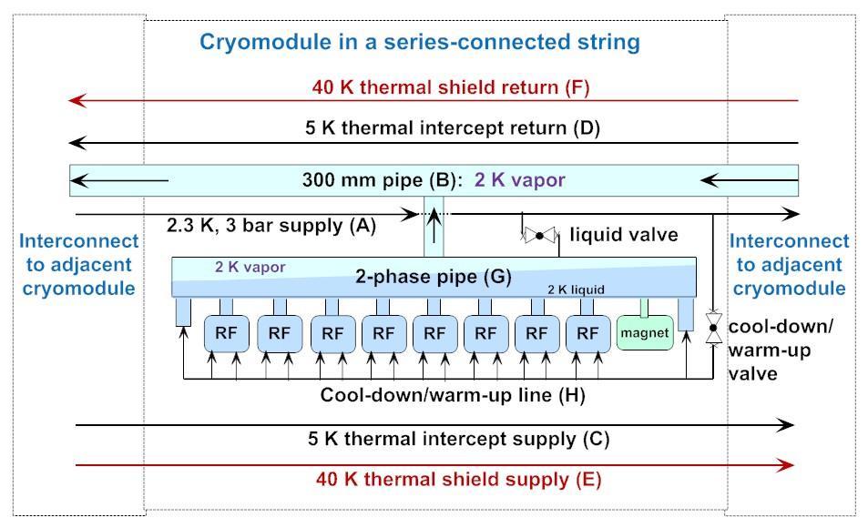
13 2-pipe 2 Kelvin vapor system 650 MHz cryomodule a modified TESLA-type 13

14 TTF cryomodule cross-section 14
15 Heat transport vertically to surface Recall from our normal fluids behavior discussion, the pressure head of liquid helium and Clapeyron Equation tell us that helium saturation temperature increases by about 1.5 mk/cm of depth. Substituting K/cm into equation (3) on slide 12 results in 1.2 W/cm 2 heat flux vertically to the surface of the helium II. Note that this heat flux is essentially independent of depth for the depths of 10 s of cm typical of RF helium vessels. I use 1 W/cm 2 as a limit for sizing a conduit for heat transport to the surface of a saturated helium II bath. 15
16 Helium vessel style Helium vessel style (open vs. closed) is independent of support style (hung from 300 mm pipe, space frame, rails) High heat loads and tight pressure stability ==> Large liquid-vapor surface area for liquid-vapor equilibrium Acts as thermal/pressure buffer with heat and pressure changes Linac is short enough that total helium inventory not an issue ==> Open helium vessel is feasible For the stand-alone CW cryomodule, a closed TESLA-type helium vessel may be favored by Tuner design Input coupler design And allowed by reduced pressure sensitivity 16

17 Helium vessel style and pressure stability Rate of return to vapor-liquid equilibrium following a pressure change is limited by the rate of heat transport through the chimney for the closed helium vessel. Rate based on surface areas is about a factor 60 higher for the open vessel. 17
18 Cryomodule Pipe Sizing Criteria Heat transport from cavity to 2-phase pipe 1 Watt/cm 2 is a conservative rule for a vertical pipe (less heat flux with horizontal lengths) Two phase pipe size 5 meters/sec vapor speed limit over liquid Not smaller than nozzle from helium vessel Gas return pipe (also serves as the support pipe in TESLAstyle CM) Pressure drop < 10% of total pressure in normal operation Support structure considerations Loss of vacuum venting P < cold MAWP at cavity Path includes nozzle from helium vessel, 2-phase pipe, may include gas return pipe, and any external vent lines 18
19 Cryomodule requirements -- typical vessel and piping pressures 19
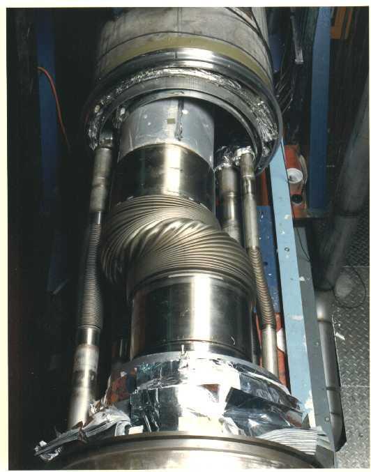
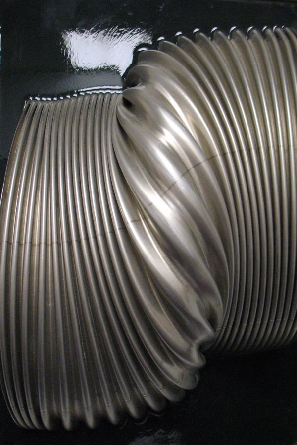
20 Pressure-induced pipe instability 20
21 Lateral elastic pipe instability Lateral displacement force is proportional to lateral displacement and to pressure If the restoring spring constant of the piping system in which the bellows is installed is less than the constant relating lateral displacement force to lateral displacement (a negative spring constant ) at a given pressure, the system is transversely, elastically unstable at that pressure. Relatively light pipe supports near the bellows can prevent this instability by adding stiffness. 21
22 Displacement force proportional to displacement 22
23 Pipe instability analysis Lateral pipe instability: displacement force is proportional to displacement (unpublished paper by P.O. Mazur, Fermilab) F(P) = PAsin(Q max ) where F(P) is the lateral force as a function of pressure, P is pressure in the system (vacuum outside), A is bellows areas, and Q max is the maximum angle of displaced convolutions Q max = 3Y/(2(L+X)), where X, Y, and L are shown in the previous figure For small angles, F(P)/Y = 3 PA/(2(L+X)) Instability occurs when F(P)/Y exceeds the restoring spring constant, determined by bellows and pipe stiffness 23
 Pipe supports are added at each end and at the center for")
24 US LHC high gradient quad (Q2P1) cold mass, support rings, and internal piping (from Tom Nicol, Fermilab) Pipe supports are added at each end and at the center for stability 24
25 Axial pressure forces Walls in tension Bellows does not carry tensile load Pressure-containing pipes and vessels carry tension in their walls due to pressure forces Introduction of a bellows or elastic element introduces the possibility of unbalanced forces on the piping Combination of bellows and elbow are often overlooked The following slide shows a free body diagram for a helium vessel within a cryogenic supply box for LHC at CERN 25
26 Forces on DFBX-E due to 20 bar M1 line pressure plus 3.5 bar in the helium vessel 66.8 kn (15000 lbf) (Combined pressure and gravity) 10.0 kn (2250 lbf) x mm (25.0 in) 20.0 kn (4500 lbf) 20.8 kn (4680 lbf) x 2 (rods in tension) 767 mm (30.2 in) 12.5 kn (2820 lbf) x 2 (rods in tension) 26
27 Temperature (K) Thermal intercepts Stainless steel in pure conduction With no thermal intercept, assume a heat flux of 1 W/sq.cm. to 2.0 K No intercept 80 K intercept Then adding an 80 K intercept at the midpoint results in 0.23 W/sq.cm. to 2.0 K and 1.77 W/sq.cm. to 80 K Position 27
28 Thermal intercept benefit From previous illustration: No thermal intercept: 1 W/sq.cm. to 2 K x 700 W/W = 700 W of room temperature power per sq.cm. of rod between 2 K and 300 K With thermal intercept: 0.23 W/sq.cm. to 2 K x 700 W/W W/sq.cm. to 80 K x 12 W/W = 161 W + 21 W = 182 W of room temperature power per sq.cm. of rod between 2 K and 300 K 28
29 S1-Global cryomodule Tested at KEK in A TESLA-type cryomodule but consisting of two 4-cavity cryomodules joined end-toend Cavities from FNAL, DESY, KEK Thoroughly instrumented and careful heat load studies conducted by Norihito Ohuchi (KEK) 29
30 From Norihito Ohuchi (KEK) 30
31 Measured thermal radiation heat Measured in above-mentioned S1-Global studies at KEK 1.62 W/m 2 from 300 K to 80 K thermal shield W/m 2 from 80 K thermal shield to 5 K thermal shield My rule of thumb (pre-dates S1-Global) 1.5 W/m 2 from 300 K to 80 K thermal shield 0.05 W/m 2 from 80 K thermal shield to 5 K thermal shield 31
32 Electron side Positron side Baseline Configuration Layout Pre-accelerator RTML Electron linac Beam delivery Positron linac Keep-alive Booster RTML DR cavities Undulator DR wigglers Cryo-unit Crab-cavity Final doublet Damping ring Damping ring Electron side Positron side Reference Design Layout RTML Electron linac Undulator Booster Keep-alive Crab-cavity Final doublet DR wigglers Beam delivery Damping ring Pre-accelerator Cryo-unit DR cavities Positron linac Legend: RTML 2 K cryoplants 4.5 K cryoplants Distribution boxes Transfer lines Tom 32
33 Cryogenic unit length limitations 25 KW total equivalent 4.5 K capacity Heat exchanger sizes Over-the-road sizes Experience Cryomodule piping pressure drops with 2+ km distances Cold compressor capacities With 192 modules, we reach our plant size limits, cold compressor limits, and pressure drop limits 192 modules results in 2.47 km long cryogenic unit 5 units (not all same length) per 250 GeV linac Divides linac nicely for undulators at 150 GeV Tom 33
34 Heat loads scaled from TESLA TDR Cryomodule TESLA ILC ILC and refers to the number of cavities in the E, [MV/m] G Q 1.E+10 1.E+10 Rep rate, [Hz] Number of Cavities avg number of cavities per module Fill time [µsec] Tf Beam pulse [µsec] Tb Number of bunches Nb Particles per bunch [1e10] Qb Gfac 2.09 Stored Energy Factor = G^2*(Tb + 1.1*Tf) Pfac 1.54 Input Power Factor = G*(Tb + 2*Tf)*Cfac Bfac 0.99 Bunch Factor = Nb*Qb^2 Cfac 0.95 Beam Current Factor = Qb*Nb/Tb Tom 34
35 Module predicted heat loads -- 2K TESLA ILC Static Dynamic Static Dynamic Temperature Level 2K 2K RF load Dynamic load scaled by the number of cavities and Gfac Supports Assume independent of nuimber of cavities Input coupler Static load scaled by number of cavities, dynamic by Pfac also HOM coupler (cables) Static and dynamic load scaled by number of cavities, dynamic by Cfac also HOM absorber Dynamic load scaled by Bfac Beam tube bellows Dynamic load scaled by the number of cavities and Gfac Current leads Weigh by a factor of 1/3 since only 1 in 3 modules have quads** HOM to structure Static load scaled by the number of cavities, dynamic by Bfac also Coax cable (4) Assume indepent of nuimber of cavities Instrumentation taps Assume indepent of nuimber of cavities Scales as Gfac Scales as Pfac Independent of G,Tf Static, dynamic sum Total for RF unit below 2K Sum [W] Tom 35
36 Module predicted heat loads -- 5K TESLA ILC K 5K Radiation Static load scaled by number of cavities Supports Assume indepent of nuimber of cavities Input coupler Static load scaled by number of cavities, dynamic by Pfac also HOM coupler (cables) Static and dynamic load scaled by number of cavities, dynamic by Cfac also HOM absorber Dynamic load scaled by Bfac Current leads Weigh by a factor of 1/3 since only 1 in 3 modules have quads** Diagnostic cable Assume independent of nuimber of cavities Scales as Pfac Independent of G,Tf Static, dynamic sum Total for RF unit below 5K Sum [W] Tom 36
37 Module predicted heat loads -- 40K TESLA ILC K 40K Radiation Static load scaled by number of cavities Supports Assume indepent of nuimber of cavities Input coupler Static load scaled by number of cavities, dynamic by Pfac also HOM coupler (cables) Static and dynamic load scaled by number of cavities, dynamic by Cfac also HOM absorber (3.27) (3.27) Dynamic load scaled by Bfac Current leads Weigh by a factor of 1/3 since only 1 in 3 modules have quads** Diagnostic cable Assume indepent of nuimber of cavities Scales as Pfac Independent of G,Tf Static, dynamic sum Total for RF unit below 40K Sum [W] Tom 37
38 Use Power required for a nonisothermal load Where P is the ideal room-temperature power required to remove a non-isothermal heat load I will show the use of this later in calculating the ILC cryogenic system power Tom 38
39 Cryogenic unit parameters 40 K to 80 K 5 K to 8 K 2 K Predicted module static heat load (W/module) Predicted module dynamic heat load (W/module) Number of modules per cryo unit (8-cavity modules) Non-module heat load per cryo unit (kw) Total predicted heat per cryogenic unit (kw) Heat uncertainty factor on static heat (Fus) Heat uncertainty factor on dynamic heat (Fud) Efficiency (fraction Carnot) Efficiency in Watts/Watt (W/W) Overcapacity factor (Fo) Overall net cryogenic capacity multiplier Heat load per cryogenic unit including Fus, Fud, and Fo (kw) Installed power (kw) Installed 4.5 K equiv (kw) Percent of total power at each level 18.0% 21.8% 60.2% Total operating power for one cryo unit based on predicted heat (MW) 3.34 Total installed power for one cryo unit (MW) 4.28 Total installed 4.5 K equivalent power for one cryo unit (kw) Tom 39
40 CERN LHC capacity multipliers We have adopted a modified version of the LHC cryogenic capacity formulation for ILC Cryo capacity = Fo x (Qd x Fud + Qs x Fus) Fo is overcapacity for control and off-design or off-optimum operation Qs is predicted static heat load Fus is uncertainty factor static heat load estimate Fud is uncertainty factor dynamic heat load estimate Qd is predicted dynamic heat load Tom 40
41 Heat Load evolution in LHC Basic Configuration: Pink Book 1996 Design Report: Design Report Document 2004 Temperature level Heat load increase w/r to Pink Book Main contribution to the increase K 1,3 Separate distribution line 4-20 K 1,3 Electron-cloud deposition 1,9 K 1,5 Current lead cooling 1,7 Beam gas scattering, secondaries, beam losses Separate electrical feeding of MB, MQF & MQD At the early design phase of a project, margins are needed to cover unknown data or project configuration change. Tom 41
42 Cryogenic system design Fairly complete accounting of cold devices with heat load estimates and locations Some cold devices still not well defined Some heat loads are very rough estimates Cryogenic plant capacities have been estimated Overall margin about 1.54 Main linac plants dominate, each at K equiv. Component conceptual designs (distribution boxes, end boxes, transfer lines) remained sketchy Need these to define space requirements and make cost estimates Used area system lattice designs to develop transfer line lengths and conceptual cryosystem layouts Tom 42
43 Cryomodule string segmentation Various degrees of possible segmentation Total isolation and warm-up with adjacent cryomodule cold Total separation of vacuum and cryogenic circuits but no provisions for maintaining segments cold which are adjacent to warm cryomodules Limits extent of control lengths and vacuum No end buffer from adjacent cold segment for vacuum let-up of warm segment. E.g., one must warm three segments to let up one. Segments downstream of warm one may not be held cold Vacuum isolation and/or cryo circuit extent of various lengths, not all equal For example, liquid flow path shorter than thermal shield circuits Some valves distributed more finely than others. May have small feed boxes or valves in cryomodules for 2 K liquid supply. Relief valve frequency -- low MAWP may force frequent vents Pipe sizes trade off with segmentation lengths 43


44 SNS vs TTF cryomodule SNS (like CEBAF): self-contained vacuum vessel stand-alone style TTF: vacuum vessel string. End boxes and bellows would become part of vacuum/pressure closure 44
45 Advantages of separated cryomodules (1) 1. Separated liquid management. High heat loads for high duty factor or CW cryomodules imply high 2 Kelvin boil off rates. Managing the liquid level in the helium vessels and flow through the JT valve and 2-phase pipe or series of helium vessels will be easier with a shorter length of liquid baths. 2. Prefer small heat exchangers, distributed with cryomodules. In general, in my opinion, a JT heat exchanger of a size comparable to those in LHC which place the heat loads in the large transfer line at the 4.5 K level will be preferable. 3. Warm magnets and instrumentation between cryomodules. Separate cryomodules allow warm beam line components between cryomodules, especially useful for easier alignment of magnets and BPM's, other instrumentation, and also for absorbing some HOM power if applicable. 4. Active pumping between cryomodules. If needed, the insulating vacuum of a single cryomodule may be pumped, and the beam vacuum is accessible for pumping. 45
46 Advantages of separated cryomodules (2) 5. Loss of insulating vacuum to air is limited to one cryomodule (assuming vacuum isolation from the transfer line). The sudden rush of air into insulating vacuum and resulting heat fluxes with air condensation can deposit up to several Watts per square cm on liquid helium-temperature vessels and piping, depending on insulation. For a string of cryomodules, this can result in huge flow rates with requirements for extremely large vent lines and venting devices. The separate cryomodule vacuums limit this disaster to one cryomodule for the insulating vacuum loss. 6. Replacement for maintenance. Separate cryomodules allow replacement of individual cryomodules without warming the entire string. 7. Testing and commissioning. Separate cryomodules allow installation and cryogenic operation of individual cryomodules or parts of the linac during installation and commissioning. 8. Incorporation and connection of low-beta cryomodules of different types, for example FRIB. Separated cryomodules will reduce constraints imposed by matching cold interconnects and allow easier transitions among different types of cryomodules, also allowing the top-loading configuration. 46

47 Stand-alone cryomodule schematic 47
48 Advantages of string 1. No external transfer line. A large transfer line with vacuum-jacketed 4 K pumping line may be $5000 to $10,000 per meter including all the connections to the cryomodules. So for a 10 meter long cryomodule, it may add the equivalent of another $50K to $100K or so to the CM cost, as well as occupy tunnel space. I think the external transfer line cost is the major cost difference between these two configurations. Incorporation of the transfer line into the cryomodule piping was one of the main motivations for the TESLA design. 2. Fewer cryogenic valves. By placing the helium vessels and other piping of multiple cryomodules in series, one valve at a feed or turnaround box controls the flow through many cryomodules. This may provide significant cost reduction (in addition to the elimination of the external transfer line) and also simplify operations (assuming control of the long volumes is not a problem) by resulting in fewer control valves. 3. No warm-cold transitions at the ends. Especially for systems with relatively low dynamic heat loads where static heat load is more significant, eliminating the warm-cold transitions at each end helps reduce heat load. It may also result in a simpler end since one just has a connection to another pipe, no turn-arounds or pressure-load-bearing ends. However, I do not believe that closing the end is more expensive (as some have claimed) than the huge vacuum bellows and other features of an interconnect. 48
49 ILC cryomodule cooling scheme Still essentially unchanged from the TESLA scheme 49

50 From Shrikant Pattalwar, STFC Daresbury, UK 50
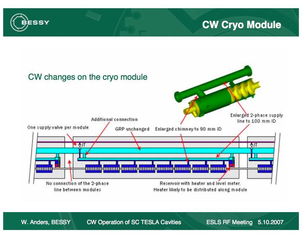
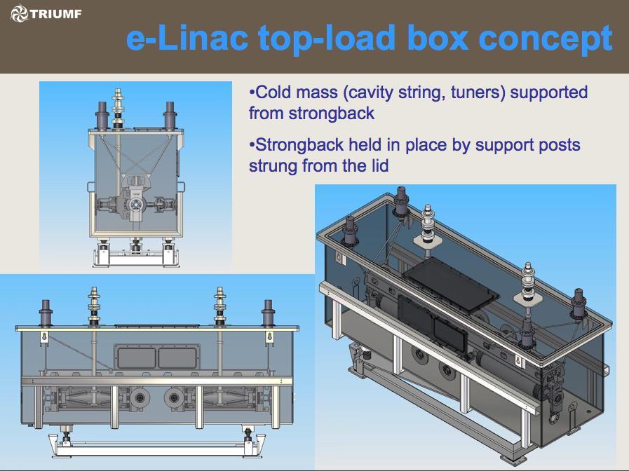
51 Various cryomodule concepts Single Spoke Resonator (SSR) cryostat concept using support posts under the cavities and magnets TESLA/ILC SNS/Jlab 12 GeV upgrade style space frame supports Closed-ended TESLA style BESSY/HZB CW cryomodule string rather than standalone cryomodules Cornell s ERL cryomodule ANL/FRIB/TRIUMF-style top-loading rectangular cryostats 51

52 SSR cryomodule concept Vacuum vessel end removed Support structure is a cradle on which magnets and cavities are supported 52

53 SSR cryomodule concept Heat exchanger Current leads Input couplers 48 inch diameter vacuum vessel 53

54 SSR cryomodule concept Still working on conceptual design as 3-D model, but becoming a complete model Heat exchanger Cavity helium vessel Bayonet connection Control valve Vent line with check valve 54

55 TESLA-style Cryomodule 55

56 Cutaway view of cavity within a cryomodule 56

57 Closed ended TESLA style 57
58 58

59 ERL cryomodule features Figure 1 from CRYOGENIC HEAT LOAD OF THE CORNELL ERL MAIN LINAC CRYOMODULE, by E. Chojnacki, E. Smith, R. Ehrlich, V. Veshcherevich and S. Chapman, Cornell University, Ithaca, NY, U.S.A. Published in Proceedings of SRF2009, Berlin, Germany 59
60 ERL cryomodule features TESLA-style support structure -- dressed cavities hang from gas return pipe (GRP), but Titanium GRP No invar rod, no rollers 6 cavities per CM, 9.8 m total CM length HOM absorbers at K between cavities GRP split with bellows at center, 4 support posts Helium vessels pinned to GRP Some flexibility in the input coupler De-magnetized carbon-steel shell for magnetic shielding (this is like TTF) 2-phase pipe closed at each CM end, JT valve on each CM (like BESSY design) String rolls into vacuum vessel on rails 60

61 LCLS-II cryomodule flow scheme 61

62 FRIB cryomodule bathtub style for comparison 62

63 TRIUMF cryomodule concept bathtub style with 1.3 GHz cavities for comparison 63
64 64
65 Conclusions Cryomodule must be designed as part of the larger cryogenic system Vacuum and cryogenic line segmentation choices depend on heat loads as well as various mechanical, alignment, and reliability considerations Off-design requirements such as emergency venting may determine line sizes and design features There is no single best design configuration. A variety of quite different designs already exist with features appropriate to the various specific applications 65
66 References -- 1 ASME Boiler & Pressure Vessel Code, 2007 Edition, July 1, 2007 Primarily Section VIII, Division 1 and Division 2 ASME B , Process Piping, ASME Code for Pressure Piping R. Byron Bird, Warren E. Stewart, Edwin N. Lightfoot, Transport Phenomena, John Wiley &Sons, S. W. VanSciver, Helium Cryogenics, Plenum Press, CGA S-1.3, Pressure Relief Device Standards, Compressed Gas Association,
67 References -- 2 Fermilab s ES&H Manual (FESHM) pressure vessel standard, FESHM FESHM Chapter Dressed Niobium SRF Cavity Pressure Safety And associated document: Guidelines for the Design, Fabrication, Testing and Installation of SRF Nb Cavities, Fermilab Technical Division Technical Note TD
68 References -- 3 W. Lehman and G. Zahn, Safety Aspects for LHe Cryostats and LHe Transport Containers, ICEC7, London, 1978 G. Cavallari, et. al., Pressure Protection against Vacuum Failures on the Cryostats for LEP SC Cavities, 4th Workshop on RF Superconductivity, Tsukuba, Japan, August, 1989 M. Wiseman, et. al., Loss of Cavity Vacuum Experiment at CEBAF, Advances in Cryogenic Engineering, Vol. 39, 1994, pg T. Boeckmann, et. al., Experimental Tests of Fault Conditions During the Cryogenic Operation of a XFEL Prototype Cryomodule, DESY. 68
69 References -- 4 E. G. Brentari, et. al., Boiling Heat Transfer for Oxygen, Nitrogen, Hydrogen, and Helium, NBS Technical Note 317, NBS Technical Note 631, Thermophysical Properties of Helium-4 from 2 to 1500 K with Pressures to 1000 Atmospheres, Vincent D. Arp and Robert D. McCarty, Thermophysical Properties of Helium-4 from 0.8 to 1500 K with Pressures to 2000 Atmospheres, National Institute of Standards and Technology (NIST) Technical Note 1334, HEPAK (by Cryodata, Inc.) 69
70 References -- 5 Flow of Fluids through Valves, Fittings, and Pipes, Crane Technical Paper #410. R.H. Kropschot, et. al., Technology of Liquid Helium, NBS Monograph 111 Ascher H. Shapiro, The Dynamics and Thermodynamics of Compressible Fluid Flow, Wiley, J.G. Weisend II, ed., Cryostat Design: Case Studies, Principles and Engineering, Springer International Publishing,
Magnet and RF Cavity Test Stand Design. Tom Peterson, SLAC USPAS January, 2017
 Magnet and RF Cavity Test Stand Design, SLAC Outline Test dewars and test stands Saturated bath test dewars Double bath test dewars SRF test cryostats SRF cryomodule test stands Horizontal magnet test
Normal Cryogenic Fluid Behavior (emphasis on helium, but not superfluid, which will be covered later) Tom Peterson, SLAC January 2017
 Tom Peterson, SLAC January 2017") Normal Cryogenic Fluid Behavior (emphasis on helium, but not superfluid, which will be covered later), SLAC January 2017 Outline Cooling modes for superconducting devices Forced flow cooling Two-phase
Normal Cryogenic Fluid Behavior (emphasis on helium, but not superfluid, which will be covered later), SLAC January 2017 Outline Cooling modes for superconducting devices Forced flow cooling Two-phase
Cryogenics of SRF Spoke Cavity Development at SMTF
 Cryogenics of SRF Spoke Cavity Development at SMTF Michael White SRF Development Technical Division Fermi National Accelerator Laboratory May 11, 2006 Overview of Topics SMTF Overview CTF Cryogen Supply
Proposal for the Cryogenic Supply of a Single TTF / FEL - Cryomodule Test Bench
 Proposal for the Cryogenic Supply of a Single TTF / FEL - Cryomodule Test Bench TESLA Report No. 2001-09 W.D.Moeller, B.Petersen, B.Sparr Deutsches Elektronen Synchrotron Abstract A test bench for the
ESS SPOKE CRYOMODULE AND TEST VALVE BOX
 ESS SPKE CRYMDULE AND TEST VALVE BX Denis Reynet, Sylvain Brault, Patxi Duthil, Matthieu Pierens, Patricia Duchesne, Guillaume lry, Nicolas Gandolfo, Emmanuel Rampnoux, Sébastien Bousson, IPN, UMR 8608
Loss of Vacuum Experiments on a Superfluid Helium Vessel
 1 Loss of Vacuum Experiments on a Superfluid Helium Vessel Stephen M. Harrison 1 Abstract The Alpha Magnetic Spectrometer (AMS) is a particle physics experiment for use on the International Space Station
Fermilab MTF Cryogenic System & Vertical RF Cavity Test Facility. Yuenian Huang, on behalf of Fermilab, TD/TID May 11, 2006
 Fermilab MTF Cryogenic System & Vertical RF Cavity Test Facility Yuenian Huang, on behalf of Fermilab, TD/TID May 11, 2006 1 Magnet Test Facility (MTF) Tevatron magnet test stands Testing temperature range
Figure 1 The LHC cryogenic islands and plants layout
 The LHC cryogenic operation for first collisions and physics run Brodzinski K, Barth K, Benda V, Bremer J, Casas-Cubillos J, Claudet S, Delikaris D, Ferlin G, Fernandez Penacoba G, Perin A, Pirotte O,
First Experimental Data of the Cryogenic Safety Test Facility PICARD
 First Experimental Data of the Cryogenic Safety Test Facility PICARD C. Heidt, A. Henriques, M. Stamm and S. Grohmann 26 th International Cryogenic Engineering Conference 2016 in New Delhi, India KIT,
Chapter 3 Atmospheric Thermodynamics
 Chapter 3 Atmospheric Thermodynamics Spring 2017 Partial Pressure and Dalton Dalton's law of partial pressure: total pressure exerted by a mixture of gases which do not interact chemically is equal to
Numerical Tools for LCLS-II Vacuum Systems
 Numerical Tools for LCLS-II Vacuum Systems G. Lanza, D. Gill, SLAC National Accelerator Laboratory AVS, November 2 nd 2017 Doc. N. SLAC-PUB-17166 Work described in this presentation is supported by the
EXPERIENCE WITH A PRE-SERIES SUPERFLUID HELIUM TEST BENCH FOR LHC MAGNETS
 EUROPEAN ORGANIZATION FOR NUCLEAR RESEARCH European Laboratory for Particle Physics Large Hadron Collider Project LHC Project Report 388 EXPERIENCE WITH A PRE-SERIES SUPERFLUID HELIUM TEST BENCH FOR LHC
Cryomodule Maintenance Workshop Maintenance, Repair Strategies, and Fault Scenarios. J. Ozelis Senior SRF Coordinator
 Cryomodule Maintenance Workshop Maintenance, Repair Strategies, and Fault Scenarios J. Ozelis Senior SRF Coordinator Outline for Discussions Maintenance - routine/preventative maintenance Schedules Specific
Microscopy Cryogenic WORKSTATION. Performance by Design
 CRYO Microscopy Cryogenic WORKSTATION Optical cryostat for use in microscopy and spectroscopy Performance by Design RC102-CFM Microscopy Cryostat offers fast cooldown, high efficiency, excellent temperature
Development of High Efficiency 4K Two-Stage Pulse Tube Cryocooler
 Development of High Efficiency 4K Two-Stage Pulse Tube Cryocooler M. Xu, H. Takayama and K. Nakano Sumitomo Heavy Industries, Ltd. Nishi-tokyo-city, Tokyo, Japan 188-8585 ABSTRACT Sumitomo Heavy Industries
ASME Boiler & Pressure Vessel Code Analysis of the 1497 MHz High-Current Cryomodule Helium Vessel
 1.0 Introduction ASME Boiler & Pressure Vessel Code Analysis of the 1497 MHz High-Current Cryomodule Helium Vessel Katherine Wilson 28 May 2007 To minimize the hazards associated with vacuum and pressure
Earlier Lecture. In the earlier lecture, we have seen Kapitza & Heylandt systems which are the modifications of the Claude System.
 17 1 Earlier Lecture In the earlier lecture, we have seen Kapitza & Heylandt systems which are the modifications of the Claude System. Collins system is an extension of the Claude system to reach lower
PHYS 101 Previous Exam Problems
 PHYS 101 Previous Exam Problems CHAPTER 14 Fluids Fluids at rest pressure vs. depth Pascal s principle Archimedes s principle Buoynat forces Fluids in motion: Continuity & Bernoulli equations 1. How deep
JANIS OPERATING INSTRUCTIONS FOR SUPERCONDUCTING MAGNET CRYOSTATS
 OPERATING INSTRUCTIONS FOR SUPERCONDUCTING MAGNET CRYOSTATS INTRODUCTION The Janis Research Company's Superconducting Magnet/Cryostat System is one of the most versatile tools available to the scientist
Procedure of Xenon Transfer
 Procedure of Xenon Transfer Feng Zhou,MIT CC: Martina Green February 28, 2005 In this write up, we discuss the procedure on how to transfer xenon to a designed gas storage vessel that supplies xenon to
Cryostream 800 Series
 Cryostream 800 Series Cryostream 800 Series Nearly 30 years after the invention of the first Cryostream Cooler, Oxford Cryosystems is proud to announce the launch of the new 800 series Cryostream. The
SPECIFICATION FOR AN MRBR 9.4 TESLA/310MM/AS CRYO-COOLED MAGNET SYSTEM
 SPECIFICATION FOR AN MRBR 9.4 TESLA/310MM/AS CRYO-COOLED MAGNET SYSTEM Prepared by:- Magnex Scientific Limited The Magnet Technology Centre 6 Mead Road Oxford Industrial Park Yarnton, Oxford OX5 1QU, UK
RECENT PROGRESS IN POWER REFRIGERATION BELOW 2 K FOR SUPERCONDUCTING ACCELERATORS
 RECENT PROGRESS IN POWER REFRIGERATION BELOW 2 K FOR SUPERCONDUCTING AELERATORS S. Claudet, CERN, Geneva, Switzerland Abstract As a result of technico-economical optimization and quest for increased performance,
JLab Cryogenic Plant Capacities
 JLab Cryogenic Plant Capacities March 26, 2010 Rao Ganni http://www.jlab.org/div_dept/dir_off/ccr/ Thomas Jefferson National Accelerator Facility Cryogenic Plant Locations & Interconnecting Transfer Lines
Load Responsive Multilayer Insulation Performance Testing
 Load Responsive Multilayer Insulation Performance Testing S. Dye 1, A. Kopelove 1, and G. L. Mills 2 1 Quest Thermal Group, 6452 Fig Street Suite A, Arvada, CO 80004 USA 2 Ball Aerospace & Technologies
Vacuum Systems and Cryogenics for Integrated Circuit Fabrication Technology 01
 INAOE. Tonantzintla, Mexico. 2010-06-23. June 23 rd, 2010 Vacuum Systems and Cryogenics for Integrated Circuit Fabrication Technology 01 Joel Molina INAOE Microelectronics Group jmolina@inaoep.mx 1 Vacuum
PRELIMINARY RISK ANALYSIS OF THE LHC CRYOGENIC SYSTEM
 EUROPEAN ORGANIZATION FOR NUCLEAR RESEARCH European Laboratory for Particle Physics Large Hadron Collider Project LHC Project Report 324 PRELIMINARY RISK ANALYSIS OF THE LHC CRYOGENIC SYSTEM M. Chorowski,
AN EXPERIMENTAL INVESTIGATION ON HELIUM LIQUEFACTION USING TWO-STAGE GIFFORD McMAHON CRYOCOOLER
 P P P International Journal of Scientific Engineering and Applied Science (IJSEAS) - Volume-1, Issue-6, September 2015 AN EXPERIMENTAL INVESTIGATION ON HELIUM LIQUEFACTION USING TWO-STAGE GIFFORD McMAHON
National Accelerator Laboratory
 Fermi National Accelerator Laboratory FERMILAB-Conf-97/268 A 1400 Liter 1.8K Test Facility T.J. Peterson, R.J. Rabehl and C.D. Sylvester Fermi National Accelerator Laboratory P.O. Box 500, Batavia, Illinois
Dynamic Operation of a 4 K Pulse Tube Cryocooler with Inverter Compressors
 Dynamic Operation of a 4 K Pulse Tube Cryocooler with Inverter Compressors C. Wang Cryomech, Inc. Syracuse, NY 13211 ABSTRACT This paper introduces the concept of operating a 4 K pulse tube cryocooler
Overview of Earlier Lecture
 4 1 Overview of Earlier Lecture Hydrogen Helium Phase Diagram of Helium Super fluid Helium 2 Outline of the Lecture Uses of Helium 4 Thermomechanical, Mechanocaloric, Fountain, Rollin Film Effects. Sound
Storage and transfer of cryofluids
 Storage and transfer of cryofluids Christian Gianese Guilty 1: Arsène d Arsonval (1851-1940) He invented a glass container with double wall, the vacuum being done in the space between the outer and inner
Thomas Jefferson National Accelerator Facility Newport News, Virginia, 23606, USA
 PROCESS OPTIONS FOR NOMINAL 2-K HELIUM REFRIGERATION SYSTEM DESIGNS P. Knudsen, V. Ganni Thomas Jefferson National Accelerator Facility Newport News, Virginia, 23606, USA ABSTRACT Nominal 2-K helium refrigeration
Installation restrictions for length of sections should also be noted.
 Since 1966 CHART (formerly MVE) has specialized in the design and fabrication of custom cryogenic piping for liquid nitrogen, oxygen, argon, helium, and hydrogen in pipe sizes ranging from 1/4" through
Safety in Cryogenic Operations at RHIC *
 Safety in Cryogenic Operations at RHIC * Anthony Nicoletti, Dewey Lederle, Ahmed Sidi-Yehklef, Tom Tallerico, Roberto Than, Joe Tuozzolo Collider-Accelerator Department Brookhaven National Laboratory Upton,
Research activities on cryogenic safety
 Research activities on cryogenic safety Steffen Grohmann, Carolin Heidt, Andre Henriques (CERN), Christina Weber European Cryogenics Days, CERN, June 9-10, 2016 INSTITUTE OF TECHNICAL PHYSICS (ITEP) INSTITUTE
The Discussion of this exercise covers the following points: Pumps Basic operation of a liquid pump Types of liquid pumps The centrifugal pump.
 Exercise 2-3 Centrifugal Pumps EXERCISE OBJECTIVE In this exercise, you will become familiar with the operation of a centrifugal pump and read its performance chart. You will also observe the effect that
Practical Guide. By Steven T. Taylor, P.E., Member ASHRAE
 ractical Guide The following article was published in ASHRAE Journal, March 2003. Copyright 2003 American Society of Heating, Refrigerating and Air- Conditioning Engineers, Inc. It is presented for educational
Level MEASUREMENT 1/2016
 Level MEASUREMENT 1/2016 AGENDA 2 A. Introduction B. Float method C. Displacer method D. Hydrostatic pressure method E. Capacitance method G. Ultrasonic method H. Radar method I. Laser method J. Level
AIRMOUNT VIBRATION ISOLATION
 MOUNT VIBRATION ISOLATION SELECTION AND ISOLATION FORMULA Refer to the selection guide on page 33 for Airmount load and isolation capabilities. Follow this procedure: 1. LOAD CAPACITY Select one or two
Structural Design of Tank Weighing Systems
 Structural Design of Tank Weighing Systems 1. Initial observations Some essential rules must be followed when installing load cells in tanks. For example, tanks are frequently subject to weather conditions
Large Hadron Collider
 Cryo-Disasters: Life at CERN Large Hadron Collider 4-6 tons of liquid helium escaped Two of the most severely broken interconnects, which are between the magnets in LHC sectors 3 and 4. The superconducting
PRELIMINARY PIPE STRESS ANALYSIS OF HIGH PRESSURE, HIGH TEMPERATURE EXPERIMENTAL HELIUM COOLING SYSTEM
 A.K. VERMA, B.K. YADAV, A. GANDHI, A. SARASWAT, S. VERMA, E.R. KUMAR PRELIMINARY PIPE STRESS ANALYSIS OF HIGH PRESSURE, HIGH TEMPERATURE EXPERIMENTAL HELIUM COOLING SYSTEM A.K.VERMA Institute for Plasma
Exercise 4-2. Centrifugal Pumps EXERCISE OBJECTIVE DISCUSSION OUTLINE DISCUSSION. Pumps
 Exercise 4-2 Centrifugal Pumps EXERCISE OBJECTIVE Familiarize yourself with the basics of liquid pumps, specifically with the basics of centrifugal pumps. DISCUSSION OUTLINE The Discussion of this exercise
CVI Valve Line. Exceeds the industry s highest standards for reliability and performance
 CVI Valve Line Exceeds the industry s highest standards for reliability and performance Available in the most standard models with the shortest lead times in the industry Exceptional quality every CVI
Special edition paper
 Development of Train Nose Shape for Reducing Micro-pressure Waves Takeshi Kurita*, Yoichi Okumura* and Tsuyoshi Ichigi** To ensure that the micro-pressure waves generated during high speed running are
Spallation target cryogenic cooling design challenges at the European Spallation Source
 IOP Conference Series: Materials Science and Engineering PAPER OPEN ACCESS Spallation target cryogenic cooling design challenges at the European Spallation Source To cite this article: J Jurns et al 2015
Gas Vapor Injection on Refrigerant Cycle Using Piston Technology
 Purdue University Purdue e-pubs International Refrigeration and Air Conditioning Conference School of Mechanical Engineering 2012 Gas Vapor Injection on Refrigerant Cycle Using Piston Technology Sophie
A Brief Introduction to Helium Liquefaction At ITER
 ITER Cryogenic System LHe PLANTS A Brief Introduction to Helium Liquefaction At ITER ITER Organization PLANT ENGINEERING DIVISION CRYOGENIC SECTION LHe PLANTS TRO: Eric FAUVE A Brief Introduction to to
S-CO 2 Brayton Recompression Loop Design and Control
 S-CO 2 Brayton Recompression Loop Design and Control 1) Background 2) Recommended Design Features 3) Modeling Strategy IST Model Changes Transient Results Prepared by: Mike Hexemer Advanced Concepts Knolls
Vibration-Free Joule-Thomson Cryocoolers for Distributed Microcooling
 Vibration-Free Joule-Thomson Cryocoolers for Distributed Microcooling W. Chen, M. Zagarola Creare Inc. Hanover, NH, USA ABSTRACT This paper reports on an innovative concept for a space-borne Joule-Thomson
GAS SUPPLY DESIGN GUIDE
 GAS SUPPLY DESIGN GUIDE Natural Gas, Propane Gas, or Dual Fuel Fired Modulating, Condensing Boilers BENCHMARK Series Gas-Fired Boilers For models: BMK750 to BMK6000 Last Update: 06/20/2014 PR1 06/20/14
ASHRAE made significant changes in 2001 to the calculations. Fundamentals of Safety Relief Systems
 2008, American Society of Heating, Refrigerating and Air-Conditioning Engineers, Inc. (www.ashrae.org). Published in ASHRAE Journal, Vol. 50, February 2008. This posting is by permission of ASHRAE. Additional
An Investigative and Synoptic Review on Helium Liquefaction Using a Commercial 4 K Gifford- McMahon Cryocooler
 An Investigative and Synoptic Review on Helium Liquefaction Using a Commercial 4 K Gifford- McMahon Cryocooler Mahesh N 1, S A Mohan Krishna 2 1 PG Student, Vidyavardhaka College of Engineering, Mysore,
Generating Calibration Gas Standards
 Technical Note 1001 Metronics Inc. Generating Calibration Gas Standards with Dynacal Permeation Devices Permeation devices provide an excellent method of producing known gas concentrations in the PPM and
ANNEX AMENDMENTS TO THE INTERNATIONAL CODE FOR FIRE SAFETY SYSTEMS (FSS CODE) CHAPTER 15 INERT GAS SYSTEMS
 CHAPTER 15 INERT GAS SYSTEMS") Annex 3, page 2 ANNEX AMENDMENTS TO THE INTERNATIONAL CODE FOR FIRE SAFETY SYSTEMS (FSS CODE) CHAPTER 15 INERT GAS SYSTEMS The text of existing chapter 15 is replaced by the following: "1 Application This
Annex 3, page 2 ANNEX AMENDMENTS TO THE INTERNATIONAL CODE FOR FIRE SAFETY SYSTEMS (FSS CODE) CHAPTER 15 INERT GAS SYSTEMS The text of existing chapter 15 is replaced by the following: "1 Application This
Compressors. Basic Classification and design overview
 Compressors Basic Classification and design overview What are compressors? Compressors are mechanical devices that compresses gases. It is widely used in industries and has various applications How they
Series Environmental Chambers
 3119-600 Series Environmental Chambers Challenges in Non-Ambient Testing Testing at non-ambient temperatures adds another layer of challenges to your testing laboratory. Ensuring you get accurate and stable
TESLA style superconducting radio frequency (SRF) cavities
 cavities") IEEE TRANSACTIONS ON APPLIED SUPERCONDUCTIVITY, VOL. 25, NO. 3, JUNE 2015 9000305 Sudden Vacuum Loss in Long Liquid Helium Cooled Tubes Ram C. Dhuley, Student Member, IEEE and Steven W. Van Sciver Abstract
IEEE TRANSACTIONS ON APPLIED SUPERCONDUCTIVITY, VOL. 25, NO. 3, JUNE 2015 9000305 Sudden Vacuum Loss in Long Liquid Helium Cooled Tubes Ram C. Dhuley, Student Member, IEEE and Steven W. Van Sciver Abstract
Micro Channel Recuperator for a Reverse Brayton Cycle Cryocooler
 Micro Channel Recuperator for a Reverse Brayton Cycle Cryocooler C. Becnel, J. Lagrone, and K. Kelly Mezzo Technologies Baton Rouge, LA USA 70806 ABSTRACT The Missile Defense Agency has supported a research
Cryogenics The Basics. Lesson 2 D. Kashy
 Cryogenics The Basics Lesson 2 D. Kashy Lecture 1 Review Lesson 1 - Objectives Looked at common liquids and gases to get a feeling for their properties Looked at Nitrogen and Helium Discussed Pressure
Visual Observation of Nucleate Boiling and Sliding Phenomena of Boiling Bubbles on a Horizontal Tube Heater
 Proceedings of the 2 nd World Congress on Mechanical, Chemical, and Material Engineering (MCM'16) Budapest, Hungary August 22 23, 216 Paper No. HTFF 146 DOI:.11159/htff16.146 Visual Observation of Nucleate
Customer Responsibilities
 Thank you for purchasing an Agilent instrument. To get you started and to assure a successful and timely installation, please refer to this specification or set of requirements. Correct site preparation
Detector Carrier Gas Comments Detector anode purge or reference gas. Electron Capture Nitrogen Maximum sensitivity Nitrogen Argon/Methane
 Gas requirements Gases for packed columns The carrier gas you use depends upon the type of detector and the performance requirements. Table 520-1 lists gas recommendations for packed column use. In general,
HANDBOOK SAFETY DEVICES. Ed SAFETY DEVICES DS-ED 01/ ENG 1
 HANDBOOK Ed. 2017 1 CHAPTER 5 SELECTION CRITERIA FOR SAFETY VALVES CALCULATION OF THE DISCHARGE CAPACITY (Ref. EN 13136:2013) The evaluation of the minimum required discharge capacity of safety valves
Design and Performance of the Vacuum Chambers for the Undulator of the VUV FEL at the TESLA Test Facility at DESY
 Design and Performance of the Vacuum Chambers for the Undulator of the VUV FEL at the TESLA Test Facility at DESY U. Hahn, P.K. Den Hartog +, J. Pflüger, M. Rüter, G. Schmidt, E. M. Trakhtenberg + Deutsches
Next Generation Quartz Pressure Gauges
 Next Generation Quartz Pressure Gauges Rick Puccio, Ph.D. Senior Scientist Quartzdyne Houston, TX March 2, 2016 Outline Quartz Pressure Gauge Introduction Gauge Size Reduction Long Term Pressure Drift
The capacity of the cargo tank venting system (46 CFR );
;") INDUSTRY GUIDELINES FOR DETERMINING THE MAXIMUM LIQUID TRANSFER RATE FOR A TANK VESSEL TRANSFERRING A FLAMMABLE OR COMBUSTIBLE CARGO USING A VAPOR CONTROL SYSTEM This document provides guidance from the
INDUSTRY GUIDELINES FOR DETERMINING THE MAXIMUM LIQUID TRANSFER RATE FOR A TANK VESSEL TRANSFERRING A FLAMMABLE OR COMBUSTIBLE CARGO USING A VAPOR CONTROL SYSTEM This document provides guidance from the
SNS BL-13B NPDGamma Experiment
 SNS BL-13B NPDGamma Experiment Hydrogen Supply to Cryogenic Target, Relief and Vent System Design Review April 7, 2010 C-156 9:00 10:30 PM Hydrogen System Block Diagram Diagram of Major System Components
Installation Operation Maintenance
 682 Seal Cooler New generation seal cooler to meet and exceed the seal cooler requirements stated in the 4th Edition of API Standard 682 Installation Operation Maintenance Experience In Motion Description
2.8 Beam Stops Introduction. 2.8 Beam Stops
 2.8 Beam Stops 2.8 Beam Stops 2.8.1 Introduction Three very different beam stops are required for the ERL. These are the primary beam stop, tune-up stops, and moderate power stops for high-energy beams.
PRC CO ² -LASER PRESENTATION
 Page 1 of 7 PRC CO ² -LASER PRESENTATION GENERAL CHARACTERISTICS - Embedded PC104 Electronics with exchangeable software allowing very easy integration of customer specified functions: such as eg. specific
Revision 2013 Vacuum Technology 1-3 day Good Vacuum Practice 1 Day Course Outline
 Revision 2013 Vacuum Technology 1-3 day Good Vacuum Practice 1 Day Course Outline This training course outline is intended to cover the following: Introduction to vacuum Measurement Lubricated rotary pumps
Cooling Characteristics of GM-type Pulse Tube Refrigerator with Neon as Working Gas
 Cooling Characteristics of GM-type Pulse Tube Refrigerator with Neon as Working Gas J. Ko, Y.J. Hong, H. Kim, H. Yeom, S.J. Park, D.Y. Koh Korea Institute of Machinery & Materials Daejeon, Korea (S), 305-343
Customer Responsibilities
 Thank you for purchasing an Agilent instrument. To get you started and to assure a successful and timely installation, please refer to this specification or set of requirements. Correct site preparation
HOW TO MANAGE VAPORIZATION IN AN ANALYTICAL SYSTEM By Dean Slejko and Tony Waters
 HOW TO MANAGE VAPORIZATION IN AN ANALYTICAL SYSTEM By Dean Slejko and Tony Waters If the analyzer in your analytical system requires gas but your sample is liquid, the only option is to convert the liquid
LARGE CRYOGENIC SYSTEMS AT 1.8 K
 LARGE CRYOGENIC SYSTEMS AT.8 K L. Tavian, CERN, Geneva, Switzerland Abstract Cryogenics is now widely present in large accelerator projects using applied superconductivity. Economical considerations permanently
Chapter 8: Cryo-sorption pumps
 Chapter 8: Cryo-sorption pumps Cryo-sorption pumps offer a clean, quiet, safe, vibration free and inexpensive way to rough pump a vacuum system. They are often used on vacuum systems that are sensitive
Pressure Automated Calibration Equipment
 GE Measurement & control Pressure Automated Calibration Equipment Safety Instructions and User Guide - K0447 PACE5000 PACE6000 K0447 Issue No. 9 1 10 1 PACE5000 1 2 3 4 5 PACE6000 2 6 7 8 3 4 5 6 7 8 9
LEAP CO 2 Laboratory CO 2 mixtures test facility
 LEAP CO 2 Laboratory CO 2 mixtures test facility THE PROJECT AIM CO 2 flows made available by several capture techniques are contaminated with impurities and this affects the design and operations of the
Gianluca Gemme LN2 DISTRIBUTION PLANT
 Gianluca Gemme LN2 DISTRIBUTION PLANT Design parameters Cryogen Liquid Nitrogen Volume 200 l (one trap) Heat load 300 W (one trap) Trap cold mass 500 Kg Number of traps 4 Liquid nitrogen input 7.10 l/h
MET Lecture 8 Atmospheric Stability
 MET 4300 Lecture 8 Atmospheric Stability Stability Concept Stable: Ball returns to original position Neutral: Ball stays wherever it is placed Unstable: Displacement grows with time. Atmospheric Stability
Vacuum Jacketed Piping Solutions
 Acme Cryogenics VACUUM INSULATED PIPE Vacuum Jacketed Piping Solutions Preferred piping solution for the safe, reliable, cost-effective transfer of cryogenic liquids - such as liquidifed nitrogen, oxygen,
The flow direction must be observed during installation. It can be recognized by the following features: Flow direction. Gasket
 6.2 Installation of the Safety Valve The correct installation within a plant is essential for the proper operation of a safety valve. Installation in this sense is e.g. - the choice of the gaskets - the
Mid InfraRed Instrument (MIRI) Cooler Cold Head Assembly Acceptance Testing and Characterization
 Cooler Cold Head Assembly Acceptance Testing and Characterization") 1 Mid InfraRed Instrument (MIRI) Cooler Cold Head Assembly Acceptance Testing and Characterization M. Petach, M. Michaelian Northrop Grumman Aerospace Systems Redondo Beach, CA 90278 USA ABSTRACT The Cooler
1 Mid InfraRed Instrument (MIRI) Cooler Cold Head Assembly Acceptance Testing and Characterization M. Petach, M. Michaelian Northrop Grumman Aerospace Systems Redondo Beach, CA 90278 USA ABSTRACT The Cooler
Challenges in Relief Design for Pilot Plants
 Challenges in Relief Design for Pilot Plants Published on July 5, 2017 Michael Trainor Relief system design at the pilot scale presents unique challenges that don t always apply at the commercial scale.
TECHNICAL SPECIFICATION. SPC-1 Stirling Process Cryogenerator
 TECHNICAL SPECIFICATION SPC-1 Stirling Process Cryogenerator Reference 80 8013 00 Issue Date August 1, 2015 1. INTRODUCTION This document contains detailed technical information and specifications for
Customer Responsibilities
 Thank you for purchasing an Agilent instrument. To get you started and to assure a successful and timely installation, please refer to this specification or set of requirements. Correct site preparation
KM/ Stainless steel air bellows Single acting Ø 220 to 400 mm
 KM/ Stainless steel air bellows Single acting Ø to mm Stainless steel end plates Frictionless operation No maintenance or lubrication Ideal for short stroke, high-force applications High isolation level
Self-operated Pressure Regulators for special applications
 Self-operated Pressure Regulators for special applications Type 2357-31 Pressure Build-up Regulator with safety function and integrated excess pressure valve Application Pressure regulators for cryogenic
Tube rupture in a natural gas heater
 Tube rupture in a natural gas heater Dynamic simulation supports the use of a pressure safety valve over a rupture disk in the event of a tube rupture HARRY Z HA and PATRICK STANG Fluor Canada Ltd A fast
Specifications of Cryogenic vacuum jacketed valves
 TECHNICAL SPECIFICATIONS OF STORES AND DRAWINGS. SECTION - C Technical Specifications for Supply of Cryogenic Vacuum ed Control Valves Specifications of Cryogenic vacuum jacketed valves Contents 1 INTRODUCTION
Chapter 11 Waves. Waves transport energy without transporting matter. The intensity is the average power per unit area. It is measured in W/m 2.
 Chapter 11 Waves Energy can be transported by particles or waves A wave is characterized as some sort of disturbance that travels away from a source. The key difference between particles and waves is a
Short Introduction to Cryo-Pumps and Refrigerators. Dr Graham Rogers Leybold UK Ltd.
 Short Introduction to Cryo-Pumps and Refrigerators Dr Graham Rogers Leybold UK Ltd. Cryo Pumps Topics Physical principles of cryo-pumping Design and control of modern refrigerator cryo-pumps UHV and XHV
TECHNICAL SPECIFICATION. SPC-4 Stirling Process Cryogenerator
 TECHNICAL SPECIFICATION SPC-4 Stirling Process Cryogenerator Reference 80 8043 00 Issue Date August 1, 2015 1. INTRODUCTION This document contains detailed technical information and specifications for
OIL SUPPLY SYSTEMS ABOVE 45kW OUTPUT 4.1 Oil Supply
 OIL SUPPLY SYSTEMS ABOVE 45kW OUTPUT 4.1 Oil Supply 4.1.1 General The primary function of a system for handling fuel oil is to transfer oil from the storage tank to the oil burner at specified conditions
Process Nature of Process
 AP Physics Free Response Practice Thermodynamics 1983B4. The pv-diagram above represents the states of an ideal gas during one cycle of operation of a reversible heat engine. The cycle consists of the
v. Size shall be specified on drawings.
 SPECIFICATION FOR VACUUM INSULATED PIPING Part 1 General 1. Submittals a. After award of contract and before executing any manufacturing, shop drawings and specifications shall be submitted to the customer
KC Series Gas Components and Supply Design Guide
 Technical Bulletin KC Series Gas Components and Supply Design Guide GF-1030 General AERCO KC Series gas fired potable water heaters and boilers are modulating input devices that require an adequate volume
Uncertainty in the analysis of the risk of BLEVE Fireball in process plants and in transportation
 Uncertainty in the analysis of the risk of BLEVE Fireball in process plants and in transportation Joaquim Casal Centre for Studies on Technological Risk (CERTEC) EEBE, Universitat Politècnica de Catalunya