TrueBlend USER GUIDE UGB Gravimetric Blender Software Version V2.7
|
|
|
- Angelica Gardner
- 5 years ago
- Views:
Transcription


1 USER GUIDE UGB TrueBlend Gravimetric Blender Software Version V2.7 USER INSTRUCTIONS About this operating manual Warranty and liability Layout of the manual Meaning of safety information Display conventions Pictograms for safety and information Abbreviations SAFETY General Designated use Sources of danger Safety devices Warning symbols on the unit Information for the operator Information for operating and maintenance personnel TECHNICAL SPECIFICATIONS Manufacturer Specifications TRANSPORT AND SETUP Unpacking Lifting Setup Positioning controller Making connections Stowing discharge chute STRUCTURE AND FUNCTION Structure of the unit Brief description of the functional units Layout of the material hoppers Operating modes Gravimetric mode Volumetric mode Combined mode COMMISSIONING OPERATION Switching on Menu structure Navigation Starting and stopping the metering and mixing process Switching off Logging in/logging out Commissioning Mixing process Component setup GRAVICOLOR Setup Working with recipes Changing material for a component (also valid for all other components) Checking total throughout Creating reports Corporate Office: Instant Access 24/7 (Parts and Service): Parts and Services:
2
3 Copyright 2007 Conair The information contained in these operating instructions, including any translation thereof, is the property of Conair and may not be reproduced or transmitted in any form or by any means (electronic, mechanical, photocopying, recording or otherwise, nor stored in any retrieval system of any nature for any purpose) without the express written authority of Conair To every person concerned with commissioning of the devices/systems it is recommended to read thoroughly these operating instructions. Conair accepts no responsibility or liability for damage or malfunction of the equipment arising from non-observance of these operating instructions. To avoid errors and to ensure trouble-free operation, it is essential that these operating instructions are read and understood by all personnel who are to use the equipment. Should you have problems or difficulties with the equipment, please contact your local Conair partner (see list attached). These operating instructions only apply to the equipment described below. Manufacturing address: The Conair Group, Inc. 455 Allegheny Blvd. Phone: Fax: Franklin, PA USA Conair Headquarters: The Conair Group, Inc. One Conair Drive Pittsburgh, PA USA CE
4 Contents TrueBlend Contents 1.0 User instructions About this operating manual Layout of the manual Meaning of safety information Pictograms for safety and information Abbreviations Safety General Safety Hazards Safety Features Designated use Sources of danger Safety devices Position of safety devices Detachable Material Hopper Procedure Warning symbols on the unit Position of warning symbols on the unit Meaning of warning symbols on the unit Information for the operator Qualifications of personnel Information for operating and maintenance personnel Technical specifications Transport and setup Unpacking Lifting Setup Positioning controller Making connections Compressed air connection Edition: February 2007
5 TrueBlend Contents Electrical connection Hopper loader connection (option) Structure and function Structure of the unit Brief description of the functional units (Item numbers refer to diagram on previous page) Layout of the material hoppers For four component blenders For six component blenders Operating modes Gravimetric mode Volumetric mode Combined mode Start-up Operation Switching on Switch on main switch Menu structure Navigation Explanation of the navigation buttons Explanation of keypad screens Explanation of additional screen icons Starting and stopping the blending process Starting blender process (with set values or factory setting) Stopping the blending process Restarting after EMERGENCY STOP Turning off the power Stopping the blender at the end of a cycle Switching off in emergency Logging in/logging out User levels and password input (for service users only!) (Level 3) Changing password (for service users only!) (Level 3) Auto logout (for service users only!) (Level 3) Parameters/Global Reset (for service users only!) (Level 3) Edition: February
6 Contents TrueBlend 7.7 Start-up Checking functions in manual mode Calibrating Input TrueBlend Model/Name (for service users only!) (Level 3) Input TrueBlend name Activating Batch Setting Blending process Assigning components factory default setting Example of a mixing process Typical dispense cycle based (7.8.2) settings Component setup Input of material percentages Input of Material type Input Alarm mode Input Dosing retries TrueBlend Setup Setting Operating mode Setting Weigh Bin Batch weight Setting Mixing time Setting the Interval time Setting Damping Advanced Operation Settings (Password level 3 only) Working with recipes Calling recipe status Assigning an order number Save a new recipe Naming a recipe Deleting a recipe Load/view a recipe Changing material in a blender component (also valid for all other components) Detachable Material Hopper Procedure Manual cleaning: Clean-out with optional drain chute with safety interlock Checking total throughput Creating reports Reports for batches, shifts, recipes and scales Report generator TrueBlend Reports Operation System setup Panel setup System info Edition: February 2007
7 TrueBlend Contents 7.18 Maintenance Hopper loaders (Optional) Go to Material loading (conveying) overview screen Switching on hopper loaders Changes to Loader Screen Loader Alarm Settings Settings Alarm messages and troubleshooting Signaling alarm message Handling alarm messages Deciphering Alarm Messages Alarm messages and correction Troubleshooting/Mechanics Diagnostic Overview Screens Maintenance and repair Safety Qualifications of personnel Safety equipment Safety equipment Before starting work Switch off unit/disconnect from compressed air supply Inspections Checking EMERGENCY STOP function Testing safety interlock switch Test the safety interlock switch as described in Checking functions in manual mode Mixing chamber instructions Maintenance work Annual maintenance work Repair work Calibrate/adjust a sensor with no material present Replacing pneumatic cylinder on vertical dispense valve assembly Load Cell Removal and Installation for Trueblend models, TB045 and TB Load Cell Removal and Installation for Trueblend models, TB250, TB500 and TB Replacing controller Edition: February
8 Contents TrueBlend 9.7 Cleaning Cleaning material hopper and mixing chamber Decommissioning and disposal Decommissioning the unit Disposing of unit parts Appendix Menu structure Operating levels/password level Menu overview/dosing unit Menu overview/conveying System settings menu Unit settings menu Conveyor settings menu Appendix: Addendum for Retrofit Blenders Retrofit Control Blender Start up Procedures Appendix Blow off installation instruction sheet Appendix Replacing the TrueBlend Touch Screen Control Edition: February 2007
9 TrueBlend User Instructions 1.0 User instructions 1.1 About this operating manual This operating manual is a component of the TrueBlend Gravimetric blender. It contains important instructions on the correct operative and maintenance of the unit. Follow these instructions to avoid dangers, to prevent repair expenses and downtime and to increase the service life of the unit. The manual must be kept for referral with the unit at its place of use. The manual must also accompany the unit if it is rented or sold. It is directed to people who operate and repair the unit and must be read, understood and used by every person who is responsible for the following work with the unit: Transport and setup, Operation, Maintenance and repair, Correction of faults, Decommissioning and disposal. Take particular note of the chapter on, the warning notes in the various chapters. Edition: February
10 User Instructions TrueBlend 1.2 Layout of the manual This manual is classified into several main parts: User information, Safety, Technical specifications, Transport and setup, Structure and function, Operation, Maintenance and repair, Decommissioning and disposal, Appendix (menu structure). 8 Edition: February 2007
11 TrueBlend User Instructions 1.3 Meaning of safety information Safety instructions are placed before the work steps. Read the safety instructions carefully before carrying out the subsequent operation. If safety instructions are not followed, serious personal injury - possibly with fatal results - and property and environmental damage may occur! The safety instruction in this operating manual are indicated with a symbol. The symbol contains a signal word indicating how serious the danger is. A symbol with the word "DANGER" warns of an imminent danger to the health and life of persons. DANGER! If these safety instructions are not observed serious or even fatal injuries will be caused. Always observe the directions for avoiding such dangers. A symbol with the word "WARNING" warns of a possible dangerous situation for the health and life of persons. WARNING! If these safety instructions are not observed serious or even fatal injuries may be caused. Always observe the directions for avoiding such dangers. CAUTION! A symbol with the word "CAUTION" warns of a possible dangerous situation for the health and life of persons or of property and environmental damage. If these safety instruction are not observed injury or property and environmental damage may occur. Always observe the directions for avoiding such dangers. Edition: February
.")
.")
12 User Instructions TrueBlend 1.4 Pictograms for safety and information In this operating manual you will find sections of text that a re identified by pictograms. The meaning of the pictograms is described below. Pictogram for general identification of hazards. This pictogram occurs in connection with safety instructions (see 1.3 Meaning of safety information). Pictogram for hand injury. This pictogram occurs in connection with safety instructions (see 1.3 Meaning of safety information). Pictogram for electric shock. This pictogram occurs in connection with safety instructions (see 1.3 Meaning of safety information). Pictogram information for identification of important instructions, additional information and tips. Pictogram for safety gloves that warns you to wear safety gloves. 1.5 Abbreviations The following terms and abbreviations are used in this operating manual (in alphabetical order): Abbreviation CAN E-motor LED PU Meaning Controller Area Network Electric motor Light-emitting diode Polyurethane 10 Edition: February 2007
13 TrueBlend Safety 2.0 Safety 2.1 General 2.2 Safety Hazards This chapter contains basic safety instructions for working with the gravimetric batch blending unit. Observe all the instructions for the operation and maintenance of the unit in this chapter. In addition, observe the warning notices that are placed before the action directions where the operating steps are described. MIX BLADES Mix blades are driven with substantial torque. NEVER place your hand in the mix chamber unless power is completely disconnected. SERIOUS INJURY may result. ADDITIONAL MIX BLADE HAZARD Over time, mix blades may become RAZOR SHARP. Always be careful when TOUCHING or CLEANING these blades. Check for sharp edges frequently. Replace blade if a hazard exists. VERTICAL VALVES Vertical valves in hoppers SLAM CLOSED without warning. They will injure your fingers. ALWAYS keep fingers clear valve openings. NEVER use your fingers to clear an obstruction. NEVER use your fingers to move a sticking valve. Edition: February
14 Safety TrueBlend SLIDE GATE/MIX CHAMBER NEVER use your fingers to move a sticking slide gate under the mix chamber. 2.3 Safety Features SAFETY INTERLOCK SWITCH The ACCESS DOOR is equipped with a safety interlock switch that prevents the mix motor from running and the slide valves from operating. DO NOT defeat this safety switch HOPPER FINGER GUARDS Finger guards are fitted into each hopper compartment. DO NOT reach through these guards. DO NOT use your fingers to clear an obstruction below these guards. DO NOT remove these guards. 2.4 Designated use The TrueBlend gravimetric blender must be used exclusively for metering and mixing free-flowing 1 plastic granulate and additives. A total of four different materials can be metered and mixed in the TB 45 and TB 100 models. Other models for up to six different materials are available including the: TB 250, 500 and 900 model series. The following must not be metered and mixed: Foods of all types (the unit does not meet the hygienic standards), Highly abrasive materials, such as stones, sand (increased wear of unit components), Poorly free-flowing, sticky materials (materials only flow poorly, airtight seal by the pneumatic cylinder is adversely affected), Liquids and powders (airtight seal by the pneumatic cylinder is not possible). 1 as per DIN ISO Edition: February 2007
15 TrueBlend Safety Do not make any changes to the unit. Any changes may adversely affect the safety of the unit. Designated use includes following this operating manual and following the specified maintenance intervals and conditions. Please contact Conair if you have any questions about the designated use of the unit. NOTE Edition: February

16 Safety TrueBlend 2.5 Sources of danger The unit is manufactured to comply with the state of the art in technology and the generally accepted rules of safety engineering. However, operation of the unit may give rise to dangers for life and limb of the operator or third parties or damage to the unit or other property. The unit has four sources of danger, which are shown in the figure below: Fig. 1: Sources of danger [1] Electrical system/power cabinet [2] Pneumatic material seal at the outlet of the pneumatically operated vertical valves [3] Agitator in mixing chamber [4] Pneumatic seal at the discharge slide gate 14 Edition: February 2007
17 TrueBlend Safety The sources of danger and the consequences are shown in more detail below: Danger source Electrical system Consequences Fatal injury by electric shock! High voltages can cause life-threatening currents in the body and electric shock. Allow only trained and qualified electrical technicians to work on the electrical system. Before any electrical work disconnect the unit from the power supply and lock to prevent unauthorized persons switching it on. Pneumatic seal on supply hoppers Danger of injury by moving parts! Vertically moving pneumatic cylinders can cause crushing, impact and shearing injuries. Do not reach into the pneumatic seal of the supply hopper during normal operation and during manual operation. Mixer Danger of injury by moving parts! Rotating mixing blades can catch body parts and pull them in and cause life-threatening crushing, shearing and bone fracture injuries. The edges of the mixing blades can be as sharp as knives after extended operation. Never reach into the mixing chamber while the mixer is rotating. Do not extend any objects into the movement range of the mixer. Do not disable the safety interlock switch. Wear gloves when touching or cleaning the stationary mixer. Edition: February
18 Safety TrueBlend Danger source Consequences Pneumatic seal on the discharge slide gate 2 at bottom of mix chamber Danger of injury by moving parts! Horizontally moving pneumatic cylinders can cause crushing, impact and shearing injuries and bone fractures. Do not reach into the pneumatic discharge slide gate during normal operation and during manual operation. 2 The pneumatic discharge slide gate is not installed if a manual slide gate is installed and the unit is mounted directly on the injection molding machine. 16 Edition: February 2007

19 TrueBlend Safety 2.6 Safety devices Safety devices protect your health and your life. Do not operate the unit without effective safety devices. DANGER OF INJURY! WARNING! The operator runs the risk of injury if the safety devices are not operating correctly. Check that the safety devices function correctly after work has finished (see Testing the mix chamber safety interlock switch) Position of safety devices Electrical System/Power Cabinet Fig. 2: Safety devices [1] Finger guard [2] Safety interlock switch (Mix chamber door) [3] Main switch (=EMERGENCY STOP) [4] Padlock [5} Alarm beacon [6] Alarm horn Edition: February
20 Safety TrueBlend Safety device Safety guard Safety interlock switch EMERGENCY STOP switch Padlock Safety function Prevents injury by crushing and impact at the pneumatic cylinder of the supply hopper. Stops the mixer motor when the main door is opened. Stops all movement of the machine. Locks the switch to prevent unauthorized persons switching it on Detachable Material Hopper Procedure NOTE Detachable material hopper for TB45 (4 bins) TB100 (2 bins) and TB250R-4 (2 bins) models. All detachable material hoppers on the above referenced models are held in place with a captive retainer (screw) held in the hopper support frame. The retainer stabilizes the detachable hopper when mounted in the blender support frame from forces exerted on the hopper by resin weight and various types of automatic loading/receiving device(s) during normal vibration from the process. There is a separate retainer for each detachable hopper. When removing any of these detachable hoppers for cleaning or material changeover; first, remove the automatic loading/receiving device; then use the proper hex head socket or screwdriver and back out the captive retainer. Hopper can then be removed. Upon re-insertion of the detachable hopper, it is very important to re-anchor the respective hopper(s) using the captive retainer to provide stability during normal operation of the blender. Once the hoppers have been placed and anchored, the respective loading / receiving devices can be mounted. 18 Edition: February 2007

21 TrueBlend Safety 2.7 Warning symbols on the unit The instructional, warning and prohibition signs on the unit are a component of the operating manual. Observe and follow these signs in the same way as with the manual. Keep the signs clean and legible and never remove them, paint over them or stick other signs over them Position of warning symbols on the unit Fig. 3: Warning symbols on the unit Edition: February
22 Safety TrueBlend Meaning of warning symbols on the unit Symbol Meaning Explanation Warning of hazardous electrical voltage Only electrical technicians may work on the electrical system. Warning of injury to hands Do not reach into the pneumatic seal on the supply hoppers and the discharge slide gate during operation. Never touch the mixer blades. 2.8 Information for the operator The operator is responsible for the designated use of the unit Qualifications of personnel The operator is responsible for ensuring that the personnel are qualified for the requirements of their tasks. The machine must only be operated by trained and qualified person authorized by the operator. Personnel, who are apprentices, are in training or instruction may only work on the machine under the supervision of an experienced person. DANGER OF INJURY! WARNING! Improper operation and maintenance by insufficiently qualified personnel may lead to incalculable risks with negative results for persons, machine and the environment. Only qualified and authorized technicians may operate the machine and carry out repair and maintenance work. 20 Edition: February 2007
23 TrueBlend Safety 2.9 Information for operating and maintenance personnel Persons who are required to operate and maintain the unit must read and understand the operating manual, particularly the section on safety, before starting work. The following safety instructions are particularly important for avoiding personal injury and property damage: Observe all safety and danger information on the unit. Keep all unauthorized people clear of the unit. Make sure that no people are in the danger zone every time before starting the unit. Keep the operating station clear of tools, equipment and other objects. Do not place tools or other objects on the unit. Vibration can cause them fall off the unit and injure persons and/or cause property damage. Keep the unit and work area clean and make sure that granulate does not accumulate on the floor. It may cause people to slip and injure themselves. Wear work gloves when working on the stationary mixer. Work gloves protect hands and fingers from being cut. The local safety and accident prevention regulation always apply for work with the unit. Edition: February
24 Technical Specifications TrueBlend TB45-4 TPBM Side view C Front view B Top view Position 1 Position A Position 4 Position 3 Control Drain chute Purchase the optional material drain chute that readily installs to the chassis opening of the blender for fast and simple cleanout. F E D MODELS TB45-4 Performance characteristics Batch size lb {g} 1.0 {450} Maximum throughput rate lb/hr {kg/hr}* 200 {91} Bin capacity - main ingredient ft 3 {liter} 0.2 {5.7} Bin capacity - minor ingredient ft 3 {liter} 0.2 {5.7} Maximum number of materials 4 Number of vertical discharge valves 4 Number/(size) of major bin valves 2 - (40 mm) Number/(size) of minor bin valves 2 - (20 mm) Dimensions inches {mm} A - Height above mounting plate {785} B - Width {600} C - Depth {655} D - Control height 8.25 {209.6} E - Control width 9.25 {235.0} F - Control depth 4.75 {120.6} Weight lbs {kg} Installed 75 {34} Shipping 125 {57} Voltage total amps 115V/1 phase/60 hz V/1 phase/50 hz 0.5 Compressed air requirements Discharge valves ft 3 /min { liters/sec}; 1/4 in. NPT fitting Maximum loader sizes 8 inch loaders Number of loaders - 4 MOUNTING INTERFACE Dimensions shown in inches and {mm}. 1-25/32 diameter {45} 5 {127} 1-1/4 {31} Mixing chamber access door - this side of the interface. 1-7/16 {37} 7-7/8 {200} 5 {127} 3-15/16 {100} 3-3/4 {95} Mounting bolt hole size (4 holes) 7/16 inch {11.0 mm}. Predrilled 5 x 5 mounting pattern as standard. SPECIFICATION NOTES * Maximum throughput rates are based on 35 lb/ft 3 pelletized material and using all standard valve sizes. Use of reducer inserts will lower the rate shown. The optional flow control valve will mount inside the chassis in the space of the manual slide valve. Conair recommends using the optional flow control valve when mounting the blender on a stand, surge bin or hopper. Hopper positions three and four are supplied with eight inch cover plates as standard. 7-15/32 {190} Specifications may change without notice consult with a Conair representative for the most current information. 22 Edition: February 2007
25 TrueBlend TB100-4 Side view C Front view B Technical Specifications TPBM Top view Position 1 Position A Position 4 Position 3 Control Drain chute Purchase the optional material drain chute that readily installs to the chassis opening of the blender for fast and simple cleanout. F E D MODELS TB100-4 Performance characteristics Batch size lb {g} 2.2 {1000} Maximum throughput rate lb/hr {kg/hr}* 450 {204} Bin capacity - main ingredient ft 3 {liter} 0.6 {17} Bin capacity - minor ingredient ft 3 {liter} 0.3 {8} Maximum number of materials 4 Number of vertical discharge valves 4 Number/(size) of major bin valves 2 - (60 mm) Number/(size) of minor bin valves 2 - (20 mm) Dimensions inches {mm} A - Height above mounting plate 45.0 {1145} B - Width {769} C - Depth {809} D - Control height 8.25 {209.6} E - Control width 9.25 {235.0} F - Control depth 4.75 {120.6} Weight lbs {kg} Installed 160 {72} Shipping 270 {122} Voltage total amps 115V/1 phase/60 hz V/1 phase/50 hz 1.5 Compressed air requirements Discharge valves ft 3 /min { liters/sec}; 1/4 in. NPT fitting Maximum loader sizes 8 inch loaders Number of loaders inch loaders Number of loaders - 2 MOUNTING INTERFACE Dimensions shown in inches and {mm}. 2-5/32 diameter {55} 8 {203} 1-1/8 {28} Mixing chamber access door - this side of the interface. 1-1/8 {28} 10-1/4 {260} 8 {203} 5-1/8 {130} 5-1/8 {130} Mounting bolt hole size (4 holes) 9/16 inch {14.0 mm}. Predrilled 8 x 8 mounting pattern as standard. SPECIFICATION NOTES * Maximum throughput rates are based on 35 lb/ft 3 pelletized material and using all standard valve sizes. Use of reducer inserts will lower the rate shown. The optional flow control valve will mount inside the chassis in the space of the manual slide valve. Conair recommends using the optional flow control valve when mounting the blender on a stand, surge bin or hopper. Hopper position two is supplied with a 12-8 adapter and eight inch cover plate as standard. Specifications may change without notice consult with a Conair representative for the most current information. 10-7/32 {260} Edition: February
26 Technical Specifications TPBS026/0207 Side view C 1 Front view B 4 3 TrueBlend TB250-4 and TB250-6 Top view 4 position 6 position Position 1 Position 2 Position 1 Position 2 A Position 6 Position 3 Position 4 Position 3 Position 5 Position 4 Control NOTE: Side and front view drawings are model TB The bin positions change for a TB250-6 see the top view. Drain chute Purchase the optional material drain chute that readily installs to the chassis opening of the blender for fast and simple cleanout. F E D MODELS TB250-4 TB250-6 Performance characteristics Batch size lb {g} 5.5 {2500} 5.5 {2500} Maximum throughput rate lb/hr {kg/hr}* 1000 {454} 800 {363} Bin capacity - main ingredient ft 3 {liter} 1.6 {45.3} 2.7 {76.4} Bin capacity - minor ingredient ft 3 {liter} 1.6 {45.3} 1.4 {39.6} Maximum number of materials 4 6 Number of vertical discharge valves 4 6 Number/(size) of major bin valves 2 - (60 mm) 2 - (60 mm) Number/(size) of minor bin valves 2 - (30 mm) 4 - (30 mm) Dimensions inches {mm} A - Height above mounting plate {1461} 63.0 {1600} B - Width {926} {1026} C - Depth {1037} {1084} D - Control height 8.25 {209.6} 8.25 {209.6} E - Control width 9.25 {235.0} 9.25 {235.0} F - Control depth 4.75 {120.6} 4.75 {120.6} Weight lbs {kg} Installed 320 {145} 400 {182} Shipping 440 {200} 520 {236} Voltage total amps 115V/1 phase/60 hz V/1 phase/50 hz Compressed air requirements Discharge valves ft 3 /min { liters/sec}; 1/4 in. NPT fitting Maximum loader sizes 15 inch loaders - number of loaders inch loaders- number of loaders - NA 4 MOUNTING INTERFACE Dimensions shown in inches and {mm}. 3-5/32 diameter {80} 4-1/16 {103} 2-1/16 {53} Mixing chamber access door - this side of the interface. 16-5/32 {410} 12 {305} 2-1/16 {53} 8 {203} 8-1/16 {205} 8-1/16 {205} 4-1/16 {103} Mounting bolt hole size (8 holes) 9/16 inch {14.0 mm}. Predrilled 8 x 8 and 12 X 12 mounting pattern as standard. SPECIFICATION NOTES * Maximum throughput rates are based on 35 lb/ft 3 pelletized material and using all standard valve sizes. Use of reducer inserts will lower the rate shown. The optional flow control valve will mount inside the chassis in the space of the manual slide valve. Conair recommends using the optional flow control valve when mounting the blender on a stand, surge bin or hopper. TB250-4 hopper positions two and four are supplied with 12-8 adapters with eight inch cover plates as standard. TB250-6 hopper position two is supplied with a 12-8 adapter with an eight inch cover. Specifications may change without notice consult with a Conair representative for the most current information. 16-5/32 {410} 24 Edition: February 2007
27 TrueBlend TB250-R-4 Technical Specifications TPBS Side view C Front view B Top view 4 position 1 Position 1 Position A Position 4 Position 3 Control Drain chute Purchase the optional material drain chute that readily installs to the chassis opening of the blender for fast and simple cleanout. F E D MODELS TB250R-4 Performance characteristics Batch size lb {g} 5.5 {2500} Maximum throughput rate lb/hr {kg/hr}* 800 {363} Bin capacity - main ingredient ft 3 {liter} 1.6 {45.3} Bin capacity - minor ingredient ft 3 {liter} 0.3 {8} Maximum number of materials 4 Number of vertical discharge valves 4 Number/(size) of major bin valves 2 - (60 mm) Number/(size) of minor bin valves (removable) 2 - (20 mm) Dimensions inches {mm} A - Height above mounting plate {1461} B - Width {926} C - Depth {988} D - Control height 8.25 {209.6} E - Control width 9.25 {235.0} F - Control depth 4.75 {120.6} Weight lbs {kg} Installed 280 Shipping 400 Voltage total amps 115V/1 phase/60 hz V/1 phase/50 hz 3.2 Compressed air requirements Discharge valves ft 3 /min { liters/sec}; 1/4 in. NPT fitting Maximum loader sizes 15 inch loaders - number of loaders inch loaders- number of loaders - 2 MOUNTING INTERFACE Dimensions Mixing chamber access door - shown in this side of the interface. inches and {mm}. 16-5/32 {410} 12 {305} 3-5/32 diameter {80} 4-1/16 {103} 2-1/16 {53} 2-1/16 {53} 8 {203} 8-1/16 {205} 8-1/16 {205} 4-1/16 {103} Mounting bolt hole size (8 holes) 9/16 inch {14.0 mm}. Predrilled 8 x 8 and 12 X 12 mounting pattern as standard. SPECIFICATION NOTES * Maximum throughput rates are based on 35 lb/ft 3 pelletized material and using all standard valve sizes. Use of reducer inserts will lower the rate shown. The optional flow control valve will mount inside the chassis in the space of the manual slide valve. Conair recommends using the optional flow control valve when mounting the blender on a stand, surge bin or hopper. TB250R-4 hopper position two is supplied with a 12-8 adapter with an eight inch cover plate as standard. Position three and four are supplied with hand-fill lids. Specifications may change without notice consult with a Conair representative for the most current information. 16-5/32 {410} Edition: February
28 Technical Specifications TPBS Side view Front view C B TrueBlend TB500-4 and TB500-6 Top view 4 position 6 position Position 1 Position 2 Position 1 Position 2 A Position 4 Position 3 Position 6 Position 5 Position 4 Position 3 Control D NOTE: Side and front view drawings are model TB The bin positions change for a TB500-6, see the top view. Drain chute Purchase the optional material drain chute that readily installs to the chassis opening of the blender for fast and simple cleanout. F E MODELS TB500-4 TB500-6 Performance characteristics Batch size lb {g} 11 {5000} 11 {5000} Maximum throughput rate lb/hr {kg/hr}* 1550 {703} 1200 {544} Bin capacity - main ingredient ft 3 {liter} 2.7 {76.4} 2.7 {76.4} Bin capacity - minor ingredient ft 3 {liter} 2.7 {76.4} 1.35 {38.2} Maximum number of materials 4 6 Number of vertical discharge valves 4 6 Number/(size) of major bin valves 2 - (100/60 mm) 2 - (100/60 mm) Number/(size) of minor bin valves 2 - (30 mm) 4 - (30 mm) Dimensions inches {mm} A - Height above mounting plate {1600} {1600} B - Width {1026} {1026} C - Depth {1092} {1092} D - Control height 8.25 {209.6} 8.25 {209.6} E - Control width 9.25 {235.0} 9.25 {235.0} F - Control depth 4.75 {120.6} 4.75 {120.6} Weight lbs {kg} Installed 400 {182} 400 {182} Shipping 520 {236} 520 {236} Voltage total amps 115V/1 phase/60 hz V/1 phase/50 hz Compressed air requirements Discharge valves ft 3 /min { liters/sec}; 1/4 in. NPT fitting Maximum loader sizes 15 inch loaders - number of loaders inch loaders - number of loaders - NA 4 MOUNTING INTERFACE Dimensions shown in inches and {mm}. 3-5/32 diameter {80} 4-1/16 {103} 2-1/16 {53} Mixing chamber access door - this side of the interface. 16-5/32 {410} 12 {305} 2-1/16 {53} 8 {203} 8-1/16 {205} 8-1/16 {205} 4-1/16 {103} Mounting bolt hole size (8 holes) 9/16 inch {14.0 mm}. Predrilled 8 x 8 and 12 X 12 mounting pattern as standard. SPECIFICATION NOTES * Maximum throughput rates are based on 35 lb/ft 3 pelletized material and using all standard valve sizes. Use of reducer inserts will lower the rate shown. The optional flow control valve will mount inside the chassis in the space of the manual slide valve. Conair recommends using the optional flow control valve when mounting the blender on a stand, surge bin or hopper. TB500-4 hopper positions three and four are supplied with 12-8 adapters with 8 inch cover plates as standard. TB500-6 hopper position two is supplied with a 12-8 adapter and an 8 inch cover plate as standard. Specifications may change without notice, consult with a Conair representative for the most current information. 16-5/32 {410} 26 Edition: February 2007
29 TrueBlend TB900-4 Technical Specifications and TB900-6 TPBS Side view Front view Top view C B 4 position 6 position Position 1 Position 2 Position 1 Position A Position 4 Position 3 Position 6 Position 5 Position 4 Position 3 Control D NOTE: Side and front view drawings are model TB The bin positions change for a TB900-4, see the top view. Drain chute Purchase the optional material drain chute that readily installs to the chassis opening of the blender for fast and simple cleanout. F E MODELS TB900-4 TB900-6 Performance characteristics Batch size lb {g} 19.8 {9000} 19.8 {9000} Maximum throughput rate lb/hr {kg/hr}* 3500 {1588} 2800 {1270} Bin capacity - main ingredient ft 3 {liter} 4.4 {124.6} 4.4 {124.6} Bin capacity - minor ingredient ft 3 {liter} 4.4 {124.6} 2.2 {62.3} Maximum number of materials 4 6 Number of vertical discharge valves 4 6 Number/(size) of major bin valves 2 - (100 mm) 2 - (100 mm) Number/(size) of minor bin valves 2 - (60 mm) 4 - (60 mm) Dimensions inches {mm} A - Height above mounting plate {1896} 74,75 {1896} B - Width 48.5 {1229} 48.5 {1229} C - Depth 51.0 {1296} 51.0 {1296} D - Control height 8.25 {209.6} 8.25 {209.6} E - Control width 9.25 {235.0} 9.25 {235.0} F - Control depth 4.75 {120.6} 4.75 {120.6} Weight lbs {kg} Installed 550 {249} 550 {249} Shipping 700 {318} 700 {318} Voltage total amps 115V/1 phase/60 hz V/1 phase/50 hz Compressed air requirements Discharge valves ft 3 /min { liters/sec}; 1/4 in. NPT fitting Maximum loader sizes 20 inch loaders - number of loaders inch loaders - number of loaders NA 2 8 inch loaders - number of loaders NA 2 MOUNTING INTERFACE Dimensions shown in inches and {mm}. 3-15/16 diameter {100} 5-15/16 {151} 1-15/16 {49} 1-27/32 {47} Mixing chamber access door - this side of the interface. 5-27/32 {148} 19-11/16 {500} 16 {406} 8 {203} 9-27/32 {250} Mounting bolt hole size (8 holes) 9/16 inch {14.0 mm}. Predrilled 8 x 8 and 16 X 16 mounting pattern as standard. SPECIFICATION NOTES * Maximum throughput rates are based on 35 lb/ft 3 pelletized material and using all standard valve sizes. Use of reducer inserts will lower the rate shown. The optional flow control valve will mount inside the chassis in the space of the manual slide valve. Conair recommends using the optional flow control valve when mounting the blender on a stand, surge bin or hopper. TB900-4 hopper positions three and four are supplied with 12-8 adapters with eight inch cover plates as standard. TB900-6 hopper positions three and six are supplied with 12-8 adapters and eight inch cover plates as standard. Specifications may change without notice, consult with a Conair representative for the most current information. 9-15/16 {252} 19-7/8 {505} Edition: February
30 Technical Specifications Side view Front view C B TrueBlend TB TB1800-5, and TB Top view A front 4 position front 5 position 1 2 Control 6 D 3 NOTE: Side and front view drawings are shown for model TB The bin positions change for a TB and TB models, see the top view. 5 4 front 6 position F E MODELS TB TB TB Performance characteristics Batch size lbs {g} (grams or kilograms) 40 {18000} 40 {18000} 40 {18000} Maximum throughput lbs/hr {kg/hr}* 6000 {2722} 5500 {2495} 4800 {2177} Bin capacity - main ingredient ft 3 {liter} 6 {170} 6 {170} 6 {170} Bin capacity - minor ingredient ft 3 {liter} 6 {170} 4 {113} 4 {113} Maximum number of materials Number of major valves 4 (5X5) 3 (5X5) 2 (5X5) Number of minor valves 0 2 (2X5) 4 (2X5) Dimensions inches {mm} A - Height above mounting plate 94.4 {2397.8} 94.4 {2397.8} 94.4 {2397.8} B - Width 53.0 {1346.2} 53.0 {1346.2} 53.0 {1346.2} C - Depth 53.0 {1346.2} 53.0 {1346.2} 53.0 {1346.2} D - Controller height 8.25 {209.6} 8.25 {209.6} 8.25 {209.6} E - Controller width 9.25 {235.0} 9.25 {235.0} 9.25 {235.0} F - Controller depth 4.75 {120.6} 4.75 {120.6} 4.75 {120.6} Weight lbs {kg} Installed 1465 {665} 1498 {679} 1532 {695} Shipping 1715 {778} 1748 {793} 1782 {808} Voltage total amps 220V/1 phase/50 hz V/1 phase/60 hz V/3 phase/60 hz V/3 phase/50 hz V/3 phase/60 hz V/3 phase/60 hz Compressed air requirements 0.3 ft 3 90 psi { liters/sec} 3/8 in. NPT fitting Maximum loader sizes 4 DL25 3 DL25 2 DL15 2 DL25 4 DL15 2 DL25 2 DL15 3 DL25 2 AR10 2 DL25 4 AR10 2 DL25 2 AR10 4 DL20 2 DL15 4 DL20 4 DL20 2 AR10 MOUNTING INTERFACE 30 {762.0} 27 {685.8} 15 {381.0} 15 {381.0} 30 {762.0} 27 {685.8} 8 {203.2} 15 {381.0} 16 {406.4} Ø6 {Ø152.4} SPECIFICATION NOTES * Maximum throughput rates are based on 35 lb/ft 3 pelletized material and using all standard valve sizes. Use of reducer inserts will lower the rate shown. The optional flow control valve will mount inside the chassis in the space of the manual slide valve. Conair recommends using the optional flow control valve when mounting the blender on a stand, surge bin or hopper. Specifications may change without notice, consult with a Conair representative for the most current information. 8 {203.2} Dimensions shown in inches and {mm}. 15 {381.0} 24 {609.6} 28 Edition: February 2007
31 TrueBlend TB TB and TB Technical Specifications TPBS Side view Front view Top view C B A front 4 position front 5 position Control F E D NOTE: Side and front view drawings are shown for model TB The bin positions change for a TB and TB models, see the top view. front 6 position MODELS TB TB TB Performance characteristics Batch size lbs {g} (grams or kilograms) 55 {25000} 55 {25000} 55 {25000} Maximum throughput lbs/hr {kg/hr}* 9000 {4082} 8000 {3629} 7000 {3175} Bin capacity - main ingredient ft 3 {liter} 10 {283} 10 {283} 10 {283} Bin capacity - minor ingredient ft 3 {liter} 10 {283} 5 {142} 5 {142} Maximum number of materials Number of major valves 4 (6X6) 3 (6X6) 2 (6X6) Number of minor valves 0 2 (2X6) 4 (2X6) Dimensions inches {mm} A - Height above mounting plate {2832.1} {2832.1} {2832.1} B - Width 72 {1828.0} 72 {1828.0} 72 {1828.0} C - Depth 72 {1828.0} 72 {1828.0} 72 {1828.0} D - Controller height 8.25 {209.6} 8.25 {209.6} 8.25 {209.6} E - Controller width 9.25 {235.0} 9.25 {235.0} 9.25 {235.0} F - Controller depth 4.75 {120.6} 4.75 {120.6} 4.75 {120.6} Weight lbs {kg} Installed 2483 {1126} 2531 {1148} 2580 {1170} Shipping 2783 {1262} 2831 {1080} 2880 {1306} Voltage total amps 240V/3 phase/60 hz V/3 phase/50 hz V/3 phase/60 hz V/3 phase/60 hz Compressed air requirements 0.3 ft 3 90 psi { liters/sec} 3/8 in. NPT fitting Maximum loader sizes Number of 25 inch loaders MOUNTING INTERFACE 38 {965.2} 35 {889.0} 19 {482.6} 19 {482.6} 38 {965.2} 35 {889.0} 10 {252.7} 15 {381.0} 20 {508.0} Ø8 {Ø203.2} Dimensions shown in inches and {mm}. 10 {252.7} 15 {381.0} 20 {508.0} SPECIFICATION NOTES * Maximum throughput rates are based on 35 lb/ft 3 pelletized material and using all standard valve sizes. Use of reducer inserts will lower the rate shown. The optional flow control valve will mount inside the chassis in the space of the manual slide valve. Conair recommends using the optional flow control valve when mounting the blender on a stand, surge bin or hopper. Specifications may change without notice, consult with a Conair representative for the most current information. Edition: February

32 Technical Specifications TPBS Side view Front view TrueBlend TB TB3500-5, and TB Top view C B A front 4 position front 5 position Control F E D NOTE: Side and front view drawings are shown for model TB The bin positions change for a TB and TB models, see the top view. front 5 position MODELS TB TB TB Performance characteristics Batch size lbs {g} 77 {35000} 77 {35000} 77 {35000} Maximum throughput lbs/hr {kg/hr}* {5443} {4990} {4536} Bin capacity - main ingredient ft 3 {liter} 18 {510} 18 {510} 18 {510} Bin capacity - minor ingredient ft 3 {liter} 18 {510} 9 {255} 9 {255} Maximum number of materials Number of major valves 4 (6X6) 3 (6X6) 2 (6X6) Number of minor valves 0 2 (2X6) 4 (2X6) Dimensions inches {mm} A - Height above mounting plate 156 {3962} 156 {3962} 156 {3962} B - Width 72 {1828} 72 {1828} 72 {1828} C - Depth 72 {1828} 72 {1828} 72 {1828} D - Controller height 8.25 {209.6} 8.25 {209.6} 8.25 {209.6} E - Controller width 9.25 {235.0} 9.25 {235.0} 9.25 {235.0} F - Controller depth 4.75 {120.6} 4.75 {120.6} 4.75 {120.6} Weight lbs {kg} Installed 2982 {1353} 3049 {1383} 3115 {1413} Shipping 3282 {1489} 3349 {1519} 3415 {1549} Voltage total amps 240V/3 phase/60 hz V/3 phase/50 hz V/3 phase/60 hz V/3 phase/60 hz Compressed air requirements 0.3 ft 3 90 psi { liters/sec} 3/8 in. NPT fitting Maximum loader sizes Number of 25 inch loaders MOUNTING INTERFACE 38 {965.2} 35 {889.0} 19 {482.6} 38 {965.2} 35 {889.0} 19 {482.6} 10 {252.7} 15 {381.0} 20 {508.0} Ø8 {Ø203.2} Dimensions shown in inches and {mm}. 10 {252.7} 15 {381.0} 20 {508.0} SPECIFICATION NOTES * Maximum throughput rates are based on 35 lb/ft 3 pelletized material and using all standard valve sizes. Use of reducer inserts will lower the rate shown. The optional flow control valve will mount inside the chassis in the space of the manual slide valve. Conair recommends using the optional flow control valve when mounting the blender on a stand, surge bin or hopper. Specifications may change without notice, consult with a Conair representative for the most current information. 30 Edition: February 2007

33 TrueBlend Transport and Setup 4.0 Transport and setup 4.1 Unpacking MATERIAL DAMAGE! CAUTION! Forces that are exerted on the load cell from outside when attaching and removing the weigh bin load cell may damage the very sensitive load cell. Do not use excessive force or torque is applied to the load cell. 4.2 Lifting DANGER OF INJURY! WARNING! If the weight is unevenly distributed the mixing unit may tip and injure people when it is lifted. Use only the lifting lug provided to lift the mixing unit. Fig. 4: Lifting unit Edition: February
34 Transport and Setup TrueBlend 4.3 Setup The unit can be mounted on the processing machine or operated as a centralized mixing station. A frame with reservoir hopper and exhaust box is available if it is used as a centralized mixing station. The frame can be bolted to the floor. Make sure that the base is as even as possible. Make sure that the switch cabinet and main door are accessible for maintenance work at all times. Attach the separately supplied weigh bin carefully to prevent damage to the load cell. 4.4 Positioning controller IMPORTANT Please remove the protective film on the touchscreen control for optimum performance The controller for the TrueBlend can be fixed to the housing with two screws. As delivered the rear screw is used to secure the unit for transport while the front screw is attached to the screw hole. (A) The controller with the support can be swiveled by 90 by loosening the rear screw. (B) The controller can also be removed from the support and fixed to a wall or another position and connected with a 2 m (standard) or 6 m (optional) cable. The controller can be placed on a table and prevented from slipping with the four antislip feet, which are supplied with the cable. Fig. 5: Swiveling controller [1] Mounting screws [2] Rotary knob NOTE This setup not possible on model TB45 32 Edition: February 2007
![TrueBlend Transport and Setup 4.5 Making connections 4.5.1 Compressed air connection Connect the air hose [1] to the compressed air connection of the unit [2].](/docs-images/85/92441354/images/35-0.jpg "The operating pressure must be at least 0.6 MPa (87.0 psi) (6 bar). Check the operating pressure with the manometer [3] and if it is different set it to 0.6 MPa. Fig.")
35 TrueBlend Transport and Setup 4.5 Making connections Compressed air connection Connect the air hose [1] to the compressed air connection of the unit [2]. The operating pressure must be at least 0.6 MPa (87.0 psi) (6 bar). Check the operating pressure with the manometer [3] and if it is different set it to 0.6 MPa. Fig. 6: Connecting compressed air [1] Air hose [2] Compressed air connection [3] Manometer NOTE No additional compressed air consumers may be connected to the unit, because this may reduce the operating pressure. If the operating pressure is less than 0.6 MPa the loading precision may be affected Electrical connection Connect the gravimetric batch blending unit to the mains power-supply system. Check that the unit functions after assembly (see 7.7 Startup). NOTE Electrical supply must be a clean power source with nothing else on the circuit (for example self-loading loaders.) The unit must be grounded to a lug by the sensor on the back of the unit. Edition: February
36 Transport and Setup TrueBlend Hopper loader connection (option) 4 position Position 1 Position 2 Position 4 Position 3 6 position Position 1 Position 2 Position 6 Position 3 Position 5 Position 4 ( models only) Fig. 7: Connecting hopper loaders 34 Edition: February 2007
37 TrueBlend Structure and Function 5.0 Structure and function 5.1 Structure of the unit [1] Hopper loader [2] Supply hopper a. TB 45 (4 quick access bins) b. TB 100 (2 fixed, 2 quick access bins) [3] Material [4] Vertical dispense valve [5] Weighed batch [6] Level Sensor [7] Manual side gate 3 (Machine mount) [8] Mixing agitator [9] Mixed batch [10] Mixing chamber [11] Load cell [12] Pneumatic cylinder [13] Weigh bin [14] Cover for vertical valve assembly Fig. 8: Side view of unit (Typical illustration for the TB45 and TB100.) 3 Pneumatic slide gate is supplied when a blender is remote mounted, (ie. on surge bin, floor stand, etc.) and replaces the manual slide gate. The pneumatic discharge slide gate is not installed if a manual slide is installed and the unit is mounted directly on the injection molding machine. Edition: February
38 Structure and Function TrueBlend 5.2 Brief description of the functional units (Item numbers refer to diagram on previous page) The TrueBlend meters and mixes free-flowing plastic granulate (regrind and natural material) and additives. The unit mixes four to six materials, depending on model and configuration. For example, the unit has four material hoppers [2] with mounting flanges for one hopper loader 4 [1] each. All components are dispensed by pneumatic vertical cone valves [4] and are fed to the weigh bin [13], which is mounted on a load cell [11]. The pneumatic cylinder [12] opens the weigh bin. The mixture (batch) [5] falls into the mixing chamber [10] and is mixed by an electrically powered mixer [8]. The mixing chamber holds three batches. After mixing the batch [9] the mixing chamber is emptied by the pneumatic discharge slide gate (remote mount) [7]. Approximately one batch remains in the mixing chamber to ensure that the next batch can be optimally mixed. The operation of the TrueBlend is by a PLC controller. The controller receives a signal to feed material from the capacitive level sensor [6] in the mixing chamber (see also Adjust or replace level sensor). 5.3 Layout of the material hoppers 4 position Position 1 Position 2 Position 1 and 2, Main components Position 3 and 4, Additive components Controller location Position 4 Position 3 Front door (mix chamber) Fig. 9: Layout of the material hoppers 4 The material hoppers can be loaded with hopper loaders or by hand. 36 Edition: February 2007
39 TrueBlend Structure and Function For four component blenders Based on the blender size, the volume of the blender material hopper can vary. On smaller blenders, material hoppers can be removable after unlocking the retainer mechanism used for securing the hopper. This is true with all positions on the TB45 series and color/additive positions (3&4) on the TB100 series. See chart below: Model Pos 1 & 2 Pos 3 & 4 TB45 Removablewith tool Removable with tool TB100 Fixed Removable with tool TB250R-4 Fixed Removable with tool TB250-4 Fixed Fixed TB500-4 Fixed Fixed TB900-4 Fixed Fixed TB Fixed Fixed TB Fixed Fixed TB Fixed Fixed For six component blenders Six component TB blenders are also available for handling five or six component blends, or for staging additional components used in different recipes. The following chart and drawing illustrates these combinations. Edition: February
40 Structure and Function TrueBlend 6 position Position 1 Position 2 Pos 1 & 2, Main components Pos 3 & 6, Main or additive components Pos 4 & 5, Additive components Position 6 Position 3 Controller location Position 5 Position 4 Front door (mix chamber) Fig.10; Layout of six component material hoppers All the following six component blenders utilize fixed hopper positions: Model Pos 1 & 2 Pos 3 & 4 Pos 5 & 6 TB250-6 Fixed Fixed Fixed TB500-6 Fixed Fixed Fixed TB900-6 Fixed Fixed Fixed TB1800-5/6 Fixed Fixed Fixed TB2500-5/6 Fixed Fixed Fixed TB3500-5/6 Fixed Fixed Fixed 5.4 Operating modes The TrueBlend operates in three different operating modes: Gravimetric mode: all components are metered and weighed in sequence. Volumetric mode: all components are metered in sequence without weighing. Combined mode: a gravimetric cycle is followed by an adjustable number of volumetric cycles. 38 Edition: February 2007
41 TrueBlend Structure and Function Gravimetric mode The metering sequence is identical as outlined below with every metering cycle unless Precision Additive (PREC) is selected: 1 The regrind is metered by the vertical cone valve as a percentage of the whole batch and fed into the weigh bin. 2 The required quantity of natural material is calculated by the controller and dispensed as the next component. 3 The additive natural (Add N) is metered as percentage of the natural material(s). 4 The additive batch (Add B) is metered as a percentage of the total batch. The remainder of the cycle is the same with all operating modes and is described in 5.2 Brief description of the functional units. 5 Precision Additive applies to a low percentage (<2%) color or additive natural material which is a critical component of the process. The Precision Additive can only be applied to one additive natural position. When selected that material is dispensed before the natural material, but after regrind if being used. The Precision Additive is dispensed and weighed. Then the natural material is dispensed and adjusted for any minor variation with the Precision Additive to assure the proper ratio; thereby, assuring this critical component is held to the actual target setting. Then the balance (if selected) of additive naturals are dispensed to their setpoint percentages of the weighted naturals, followed by any additive batch components Volumetric mode Volumetric mode is an emergency mode and must only be used if the weighing system fails or in special circumstances. The metering sequence is identical with every metering cycle. 1 First the regrind, then the virgin material is metered through the respective vertical valves by time control and filled into the weigh bin. The load cell does not operate in volumetric mode. 2 The additives/batch and additive color are added last through the smaller vertical valves by time control. The remainder of the cycle is the same with all operating modes and is described in 5.2 Brief description of the functional units Combined mode In combined mode one gravimetric cycle is followed by up to eight volumetric cycles (number is adjustable). The total material throughput can be increased by eliminating the weighing times. The metering cycle is described in Gravimetric mode. Edition: February
.")
42 Start-up TrueBlend 6.0 Start-up IMPORTANT Please remove the protective film on the touchscreen control for optimum performance 7.0 Operation 7.1 Switching on Familiarize yourself with the basic functions of the controller before start-up (see chapter 7.7). The TrueBlend series blender is controlled at the touchscreen on the operator station controller. It can be swung forward for ease of use (see also 4.4 Positioning controller). The operation of the TrueBlend with four components and with conveying is described below. If the loader symbol is disabled in the start screen of your controller (see 7.3.1), you can ignore the section 7.19 Hopper loaders. The following prerequisites apply for operation of the unit: The unit is correctly wired (see 4.5.2). The compressed air is connected (see 4.5.1). All material hoppers are filled with the correct material Switch on main switch Switch the main switch to "l" (ON). 40 Edition: February 2007

.")
43 TrueBlend Operation The start screen appears. You are at operating level "0". Press the icon for the gravimetric batch blending unit (TrueBlend symbol) to open the "TrueBlend Status" screen. IF your unit has the blender/loader control option, Press the icon for the hopper loader to open the "Loader Status" screen. If you did not purchase the blender/loader control package, you will not see the loader icon NOTE The screen with the logout button is only displayed if the operating level is not "0". Press to switch to other operating levels (see 7.6 Logging in/logging out). When logging out of operating levels "1", "2" and "3" you automatically switch to level "0" and the logout button disappears. If there is no input, the "TrueBlend Status" screen is automatically displayed after 60 seconds. 7.2 Menu structure 7.3 Navigation For an overview of the menu structure with the various operating levels (Levels 1-3) see the appendix (see 11.1). The navigation bar is at the bottom of the screen. It contains the following buttons: Edition: February
44 Operation TrueBlend Explanation of the navigation buttons OVERVIEW (UNIT HOME) Press this button to open the program start screen. The button is visible but disabled on the "Overview" start screen. System settings menu SETTINGS From the overview screen, press this button to open a screen that enables access to various settings. The associated settings are called from the "Overview" screen. The button is visible but disabled on the "Settings" screen. Blending settings menu SETTINGS This screen is accessible from the TrueBlend status screen. 42 Edition: February 2007

45 TrueBlend Operation Loader settings screen SETTINGS This screen is accessible from the Loader Status and all other loader screens. Alarm overview screen ALARM In the event of an alarm message press this button to gain direct access to the alarm overview. The button is visible but disabled on the "Alarm Overview" screen. This screen is accessible from all screens. Dry contact available for operating remote light or horn NOTE Back button BACK Press this back button on any screen to return to the previous screen. Edition: February
.")
46 Operation TrueBlend Help button HELP Press this button to find help on specific functions (online help is not yet implemented). This is an example of a help screen. Disabled button DISABLED Navigation bar functions that are not available are disabled (grayed out). 44 Edition: February 2007
47 TrueBlend Operation Explanation of keypad screens Input with keypad When operating the controller you are prompted to input numbers or words. When the relevant input field is pressed a numeric or alphabetical keypad (separate capital and lower case) opens, which you can use to make your inputs. Confirm your input with. In the alphabetical lowercase keypad you can press to open the numeric keypad. In the numeric keypad you can press to open the alphabetical upper-case keypad and then press to open the lower-case keypad. Use the field to input spaces, colons and slashes. If you cannot switch from the alphabetic to the numeric keypad or vice versa, the fields are disabled (grayed out). Input with dropdown menu When operating the controller you are prompted to select one of the multiple values of a dropdown menu. Press the arrow. The dropdown menu opens. Select the relevant entry and highlight it by pressing it. The value is imported into the input field. Edition: February


48 Operation TrueBlend Scroll Press the right/left arrows to scroll forward and back (e.g. with settings for components or recipes) Explanation of additional screen icons Alarm display In the event of an alarm a warning triangle is displayed at the top right corner. The alarm mode can be set to specify when an alarm is displayed and how the unit behaves (see Input Alarm mode). Operating level The operating level is shown at top left. There are four operating levels. The operating levels are 0, 1, 2, and 3 (See User levels and password input). Time and station name display The top bar of the screen shows the current time and the station names. (Blender ID) The time and station name can be set in the "System Setup" screen (see 7.15 System setup). 46 Edition: February 2007
 7.4.")
49 TrueBlend Operation 7.4 Starting and stopping the blending process Starting blender process (with set values or factory setting) Press the blender icon. The TrueBlend Status screen opens. Press the button to start the blending process automatically with the last set values or the factory settings. The button signals. (green bar) Stopping the blending process Press the button to stop the metering and mixing process. The button changes to (yellow bar). The current batch will run until it is finished. When finished the display changes to (gray bar) Restarting after EMERGENCY STOP Switch the main power switch on. Switching on within two minutes: the unit continues the interrupted process. This function is used to keep downtime in the event of a short power interruption as short as possible. The screen that was last open before switching off or power failure is opened. Switching on after more than two minutes: the internal functions are completely reset after switching on. The start screen appears. NOTE If the metering cycle is interrupted, the material in the weigh bin must be removed manually before restarting. This will prevent an incorrect mix ratio. Remove the weigh bin carefully to prevent damage to the load cell and empty it (see also 7.12). Edition: February
.")
50 Operation TrueBlend 7.5 Turning off the power Stopping the blender at the end of a cycle From the Blender Status screen. Press the button. The cycle is stopped. The button switches to batch is finished to (gray bar). (yellow bar), after the If an alarm message is received when switching off and the unit does not switch off, see chapter 8 Alarms messages and trouble-shooting. NOTE Switching off in emergency Switch the main switch off. The power supply is interrupted. If the cone valve was open, it is closed. All other machine movement is stopped immediately. The batch is not finished. The main switch can also be locked manually with a lock. 48 Edition: February 2007
 (Level 3) The system covers several user levels: Level : enables access to all guest functions (no password protection) Level : enables access to all operator functions (password: 3333) Level :")

51 TrueBlend Operation 7.6 Logging in/logging out User levels and password input (for service users only!) (Level 3) The system covers several user levels: Level : enables access to all guest functions (no password protection) Level : enables access to all operator functions (password: 3333) Level : enables access to all setup functions (password: 2222) Level : enables access to all service functions (password: 1111) After logging out operating level "0" is opened. Then the user level can be changed by entering the relevant password. NOTE When you select functions that are not part of your current user level, e.g. calibration of the scales at user level "0" or "1", you will be prompted for a password to change the operating level. This is not explicitly mentioned in the following examples. Example of password input: Enter the relevant password. The operating level is changed Changing password (for service users only!) (Level 3) With level 3 access you will have the ability to view all levels of passwords and will be able to change all passwords. Level 0 and 1 can not view or change passwords. Edition: February
. From the Overview screen, Press. The \"Settings\" screen appears. Press Setup\".")

52 Operation TrueBlend Auto logout (for service users only!) (Level 3) The system has an auto logout function. This enables the system to return to operating level "0" after a specified period (default value = 15 min). From the Overview screen, Press. The "Settings" screen appears. Press Setup". to open "Password NOTE If you want to change the password press on the field beside the user level and the calculator will appear allowing you to change the password. If you change a password it is important that you note your new password. If you forget your password, contact Conair Service. Press the field beside auto logout (min) and enter the number of minutes before you will be automatically logged out. The input of "00" means that the user is never automatically logged out. In this case logout is only possible with the logout button. 50 Edition: February 2007

53 TrueBlend Operation Parameters/Global Reset (for service users only!) (Level 3) The overscreen Press the button beside "Parameters". IMPORTANT Please contact Conair service before attempting to make a change to the parameters, number or value. Currently, there are no parameter functions that can be set or changed. The "Control Variable" screen opens. Assign a parameter number and a parameter value (no function currently set). Press or depending on whether the parameters should be readout or set (no function currently set). Press at "Global Reset" to reset the controller completely. (Defaults to the home screen.) A "Global Reset" can also be done by switching off the unit for more than two minutes. Once off is pressed the unit will default to the home screen. Press the button to toggle from off to on at "Diagnostic Report" to create accuracy reports for the service. (Refer to Section 7.14 for connection options.) Edition: February
54 Operation TrueBlend 7.7 Start-up IMPORTANT Please remove the protective film on the touchscreen control for optimum performance Checking functions in manual mode All mechanical parts can be manually actuated with the "Manual Mode" function. If a vertical valve or the mix discharge is opened in manual mode, they are closed automatically by switching the main power switch to OFF or if the power fails. DANGER OF INJURY! WARNING! If you reach into the mix discharge or the dosing unit when the compressed air supply is connected, hand injury may be the result. Never reach into the mix discharge or dosing unit. Conditions for operation The safety door must be closed. In the "Overview" screen press the TrueBlend icon. The TrueBlend Status screen appears. Press. The "Settings" screen appears. Press to start manual mode. Now you can operate the material hoppers, weigh bins, mixers and discharge slide gates if supplied. 52 Edition: February 2007

55 TrueBlend Operation If the unit is running or is being calibrated, it is locked to prevent testing of the manual operation. NOTE Testing alarm beacon Press and hold the button to check that the alarm beacon and horn operates. These devices are located on the door of the electrical power box. Checking material hoppers The icons that display the status of the hoppers are at the top of the screen. Press the buttons in sequence to check that the various material hoppers valves can be opened and closed. (Shown are four hoppers, if your unit has six, all six will be displayed only on the 250, 500, 900, 1800, 2500 and 3500 models.) Edition: February

56 Operation TrueBlend Checking weigh bins, mixers and discharge slide gates Press the buttons beside the unit icon to test the function of the weigh and mix chamber components. Press the first button to open and close the weigh bin. or Press the middle button to switch the mixer on and off. or Press the bottom button to open and close the optional discharge slide gate. 5 or (Flow control valve) Note: Only functions when a pneumatic discharge slide gate is installed. Make sure that all parts of the unit can be opened and closed: Testing the mix chamber safety interlock switch The safety door must be closed. Press. The "Settings" screen appears. Press to start manual mode. 5 Only functions when a pneumatic discharge slide gate is installed. 54 Edition: February 2007

57 TrueBlend Operation To the right of the mixer icon press the middle or. The mixing blades must rotate. Open the safety door. The mixing blades must stop. Close the safety door. The mixing blades should rotate again. This screen mask will only be closed when all actions have been completed. When you open the door, the mask will appear, indicating an alarm condition. NOTE Edition: February
58 Operation TrueBlend Calibrating NOTE Conair recommends performing a manual calibration at start-up or material change with a dramatic change in the bulk density of the material being blended. This allows the blender to reach its optimal working point more quickly Calibrating load cell(s): Calibrating scales - zero calibration The scales are calibrated at the factory. The zero calibration is made to set the scales to "0". During shipment and/or operation minor deviations may occur, e.g. from single pellets of material remaining in the weigh bin or positioning of the weigh bin on the load cell support bracket. However, the controller runs an internal zero calibration tare before every cycle. Calibrating scales - full calibration A manual full weight calibration is only required after a fault, replacement of load cell(s) or for scale certification. The calibration must be conducted by authorized personnel only. The reference weights are as shown below for the various models: Conditions The weigh bin must be empty. In the "Overview" screen press the TrueBlend icon. The "TrueBlend Status" screen opens. Press. The "Settings" screen appears. Press to open the "Scale Calibration" screen. The "Scale Calibration" screen appears. It can only be calibrated with the blender stopped. The main power remains on. 56 Edition: February 2007
 (Level 3) Press to open the \"Full Calibration\" screen.")


59 TrueBlend Operation Zero calibration Press. "0" is displayed for "Actual Weight". Full calibration (for service users only!) (Level 3) Press to open the "Full Calibration" screen. Before the "Full Calibration" screen appears, you will be reminded that a full calibration cannot be interrupted: Press "Continue" if you want to proceed with the full calibration. or Press "Abort" to stop the full calibration. Make sure that the weigh bin is empty of material. Press Enter to confirm. A reference weight of 1250 g is assumed as the factory setting for a TrueBlend 100 series blender or 750 g for a TrueBlend 045 series model. Edition: February


60 Operation TrueBlend Model TB045 TB100 TB250 TB500 TB900 TB1800 TB2500 TB3500 Calibration Weight 750 g 1,250 g 3,000 g 6,000 g 10,000 g 22,000 g 30,000 g 50,000 g If you wish to change the reference weight, press the number input field and enter the desired weight. Confirm the value with. Place the reference weight in the weigh bin and confirm with. The current weight is compensated and displayed. The full calibration is complete. Confirm with. 58 Edition: February 2007
 are run with reduced batch weight(s) at startup. The optimum working point is set after several batches.")

61 TrueBlend Operation Calibrating material throughput The material throughput calibration is automatically run on startup and is selfoptimizing during production. The respective dispensing valve(s) are run with reduced batch weight(s) at startup. The optimum working point is set after several batches. A high mixing precision is quickly reached with a small quantity of material. Finally it is switched to the preset batch weight. NOTE Conair recommends performing a manual calibration at start-up or material change with a dramatic change in the bulk density of the material being blended. This allows the blender to reach its optimal working point more quickly. Conditions The weigh bin must be empty. Press on a material hopper on the "BLENDER Status" screen. or Press on a material hopper on the "TrueBlend Totals" screen. The "Setup Component" screen appears. Press to open the "Material calibration" screen. The "Material calibration" screen appears. Edition: February

62 Operation TrueBlend "1" indicates the material hopper number. You can scroll forward and back with the arrows. Press for material hopper "1". Press bin. again to empty the weigh Run the process for all components that require calibration. Important: The screen cannot be closed until the procedure is completed. For input of the material percentages, see section Input of material percentages. 60 Edition: February 2007
 (Level 3) In the \"Overview\" screen press the TrueBlend icon. The \"TrueBlend Status\" screen opens. Press.")

63 TrueBlend Operation Input TrueBlend Model/Name (for service users only!) (Level 3) In the "Overview" screen press the TrueBlend icon. The "TrueBlend Status" screen opens. Press. The "Settings" screen appears. Press to open the "TrueBlend Model/Name" screen. The "TrueBlend Model/Name" screen appears. Select the appropriate TrueBlend model in the dropdown menu (Model 45/100/250/500/900/1800/2500/3500). Edition: February

64 Operation TrueBlend Input TrueBlend name In the "Overview" screen press the TrueBlend icon. The "TrueBlend Status" screen opens. Press. The "Settings" screen appears. Press Model/Name" screen. to open the "TrueBlend The "TrueBlend Model/Name" screen appears. Assign a name to the unit with alphanumeric keypad to give it a unique identification. Confirm with Activating Batch Setting From the Blender Status screen, press the Settings navigation button. The blender Settings screen will appear as shown at right. The bottom panel on this screen allows one to access the Batch Mode screen where the Batch Mode of operation can be Turned On and setup for the amount of blended material in that batch. Setting the blender in the Batch Mode In normal operation the blender will continue to make individual blended batches of material until the level sensor is satisfied or the blender is turned off by the selection button on the Blender Status screen. When placed in the Batch Mode the blender will blend the current settings or recipe until the preset Batch Weight is accomplished and then stop. 62 Edition: February 2007


65 TrueBlend Operation To activate the Batch Mode, press the off button in the top panel position. The gray button will change to green indicating this mode is now activated. Next enter the target weight in the next panel position. The units will be either lbs or kg. If you need to change from one to the other, please refer to section 7.15 System Setup. To start the blender operating, return to the Blender Status screen and press the On/Off button. The blender will then begin to weigh the target value. You can return to the Batch Mode screen and monitor process as this is being done. NOTE The actual weighed value will be at least the target value you have entered plus up to one additional weighed batch of the blender model you are using. The reason being that the blender can t stop in the middle of an individual batch, but the actual total weight will be indicated and all the ingredients will be included in correct proportions. The next panel position on this screen will display the Current Weight which could be a portion of the target value if one is viewing during operation or the target weight if the blender has finished. The last panel on this screen displays the status of the batch mode which can be; --- (if the batch Mode is not activated), Running (if in the process of making a Batch), Finished (if the targeted batch has been completed) or Stopped (appears after the previous Batch amount has been reset). Edition: February


66 Operation TrueBlend NOTE When the target value has been reached, a screen mask will appear indicating Target weight of the dispense has been reached. There is an acknowledge button OK to remove the message. NOTE Reaching the preset target weight will also stop the blender operation. To begin another Batch after resetting, return to the Blender Status screen and press the On/Off button. 64 Edition: February 2007
67 TrueBlend Operation 7.8 Blending process Assigning components factory default setting The components are assigned at the factory as follows: Component 1: regrind Component 2: natural material Component 3: additive/natural (color) Component 4: additive/natural (color) Component 5: additive/natural (color) Component 6: additive/natural (color) The assignment of the components can also be changed (see 7.9 Component setup). 4 position Position 1 Position 2 Controller location Position 4 Position 3 Front door mix chamber Fig. 11: Layout of the material hoppersfour position models (All models) Edition: February
68 Operation TrueBlend 6 position Position 1 Position 2 Position 6 Position 3 Controller location Position 5 Position 4 Front door mix chamber Fig.12: Layout of the material hoppers six position models (only available on TB250, TB500, TB900, TB1800, TB2500, and TB3500) Position 1 Position 2 Position 1 Position 2 Position 6 Position 3 Position 3 Position 5 Position 4 a. Five Position Position 5 Position 4 b. Six Position Fig.13: Layout of five and six position models (only available on TB1800, TB2500, and TB3500) 66 Edition: February 2007
69 TrueBlend Operation Example of a mixing process Initial values: Total batch weight: 1000 g (TB Model TB100) Number of materials: 4 Settings: Regrind: 20% Natural material: AUTO (100% of balance batch after R, AB and AN taken out Additive batch: 10% Additive natural (Color): 2% Calculation: Regrind: R = Total weight of batch Percentage of regrind 1000 g 20% = 200 g Additive: AB = Batch Total weight of batch Percentage of additive 1000 g 10% = 100 g Natural material: N = 100% Natural material and additive natural (color) = 102% Percentage of natural material g 100% = g Additive natural (Color): AN = Natural material Percentage of natural material g 2% = 13.7 g Edition: February

 2% of N = 13.")
70 Operation TrueBlend Typical dispense cycle based (7.8.2) settings 1st Step: regrind is metered regrind 20% of total weight = 200 g 2nd Step: Natural material is calculated as 100% of the balance of batch = 686 g (automatically calculated/metered) 3rd Step: additive natural is metered (Color) 2% of N = 13.7 g (automatically calculated/metered) 4th Step: additive batch is metered 10% of total weight = 100 g (automatically calculated/metered) The controller must be set to match this sequence. The percentage of natural material is automatically calculated by the controller. [Sum of Natural(s) material = 100 %]. The percentages of the additive naturals are always based on the natural(s) material. The percentages of the additive batch is always based on the entire batch and therefore are metered last. 68 Edition: February 2007
71 TrueBlend Operation 7.9 Component setup If too much or too little was metered in a batch, this is compensated accordingly The metering process is self-optimizing on the next batch. The regrind is metered first and deducted from the total batch weight. If there is more than one virgin material, the percentages are interpreted as ratios of the virgin materials and dispensed next. If there are multiple additive naturals or additive batches, they are metered in order of ascending percentage of the total regardless of the sequence of the supply hoppers. The material component values for a batch are entered as percentages. Conditions The "TrueBlend Status" and "TrueBlend Totals" screens show the various material hoppers with the factory material assignment. The material types in the material hoppers can also be changed. The outer number in the hoppers shows the set value for the batch in % (TrueBlend Status) or the total weight in kg (TrueBlend Totals). Press the relevant supply hopper to open the "Setup Component" screen. Make the following settings for all components. Edition: February

72 Operation TrueBlend Input of material percentages Input the percentage for the material component by pressing the input field beside "Percent %". Input the value with the numeric keypad. Note: If using multiple naturals, they must equal 100%. Confirm the value with. The metering rate in g/s is automatically learned by the system, but by completing a manual calibration the blender hones in on the rate with greater precision Input of Material type After "Mat. type" input the component for the supply hopper. Select the desired component --- (a series of three dashes indicates an unused hopper and can be assigned to any position. It is important to note that if you are not using a hopper, material type must be set to --- ), regrind, natural material, additive batch, additive natural, or Precision Additive (The Precision Additive can only be assigned to one additive natural position on the blender.) Factory default settings are position 1, Reg.; position 2, Nat.; position 3, AddN; position 4, AddN; position 5 (if applicable), Off; position 6 (if applicable), Off. 70 Edition: February 2007

73 TrueBlend Operation Input Alarm mode Every material component can be assigned a specific alarm mode. The alarm mode shows the alarm response to overmetering or undermetering. The "Warn" mode is set for regrind and stop for natural and additives at the factory: Input Dosing retries Press the down arrow for the selection box and select the desired alarm mode : No alarm message, unit continues to run without message. Warn.: Alarm message is displayed, but unit continues to run. Stop: Alarm message is displayed, unit is stopped. The Dos. retry specifies how often material dispensing will be retried in the event of undermetering before an alarm is displayed (if alarm mode is set to "Warn" or "Stop", see Input Alarm mode). The factory setting is 4. (i.e. material will attempt four times to obtain target weight. If it fails an alarm will occur). Input the value for metering attempts with the numeric keypad. Confirm the value with. Edition: February
 in the center of the \"TrueBlend Status\" screen. The TrueBlend setup will come up. 7.10.")
74 Operation TrueBlend 7.10 TrueBlend Setup Operating mode, batch weight, mixing time and interval time can be set in True- Blend Setup. Press the TrueBlend body icon (green column) in the center of the "TrueBlend Status" screen. The TrueBlend setup will come up Setting Operating mode The operating mode specifies whether the unit will operate gravimetrically, volumetrically or in mixed operating mode (see Operating modes). Press the dropdown menu and select the operating mode. grav.: all components are metered and weighed in sequence (gravimetrically). volu.: all components are metered in sequence without weighing (volumetrically). mix. 1-8: a gravimetric cycle is followed by a number (1-8) of volumetric cycles. The number shows how many volumetric cycles will follow a gravimetric cycle. 72 Edition: February 2007
.")
75 TrueBlend Operation Setting Weigh Bin Batch weight Materials with a lower bulk densities (ca. <35 lb/cu ft) may not fit in the weigh bin and granulate may overflow. The batch weight must be reduced in this case. The factory setting is 900 g for the TB100 model or 400 g for the TB045 model, (see chart below). Model Batch Weight Min Weight Maximum Weight TB g 280 g 480 g TB g 630 g 1100 g TB g 1750 g 3000 g TB g 2800 g 5000 g TB g 5700 g 9800 g TB g g g TB g g g TB g g g Press the input field beside "Batch Weight and input the desired batch weight with the keypad. Confirm the value with. If the minimum value is not reached, the minimum value from the chart is automatically input. If the maximum value is exceeded, the maximum allowable value is automatically input. The batch weight can also be increased for heavy bulk materials. This will make the material throughput in lbs/hr somewhat higher. Make sure that the weigh bin does not overflow. Edition: February

76 Operation TrueBlend Setting Mixing time The mixing time shows how long a batch is mixed after discharge from the mixer. The factory setting is 10 to 15 seconds, depending on model. Press the input field beside "Mix. time" and input the desired duration in seconds with the keypad. Confirm the value with Setting the Interval time The interval time shows the time for which the mixer will jog several rotations to ensure that the mixing blades do not stop in front of the sensor and thus generate a "FULL" message. The factory setting is 30 seconds. Press the input field beside "Interval (s)" and input the desired duration in seconds with the keypad. Confirm the value with Setting Damping The following settings are available for impact and vibration damping: Select values < 2 to increase the sensitivity of the scales. Select values > 2 to reduce the sensitivity of the scales and to reduce alarm messages. The factory setting for damping is "2". 74 Edition: February 2007
 The parameters that are accessible through these menus are available for advanced users, unusual operating conditions, or setup of the control for blender retrofit")
77 TrueBlend Operation Advanced Operation Settings (Password level 3 only) Advanced Operation Settings are accessed through the Operating Times (Oper. Times) tab from the blender settings screen. Extrusion process (100%) The parameters that are accessible through these menus are available for advanced users, unusual operating conditions, or setup of the control for blender retrofit applications. It should not be necessary for these parameters to be changed in the majority of cases. Please consult with Conair service before you change any of these parameters. A. Settling times Edition: February

78 Operation TrueBlend The settling time is the time after a component dispensed into the weigh bin, while multiple weight reading are taken. (This time allows the material to settle and the load cells to recover from the dumping process before the final weight reading is taken.) The time should be entered in milliseconds For example, in the above screen shot 1500 milliseconds is entered which equals 1.5 seconds. For most Trueblend applications the default time of 1500 milliseconds should be acceptable. In retrofit applications where slow screw feeders are used these times may need to be increased to allow the material to drop from the feeders. B. Batch times Batch Settling time The Batch settling time is the time prior to beginning a batch, where the blender waits for the weigh bin to settle and return to the tare weight. Weigh Bin Open time The weigh bin open time is the time that the weigh bin is actually open as the material is dumped into the mixing chamber. Second Dump time The second dump time is the length of time that the weigh bin opens a second time to knock off any additional material that may remain in the weigh bin. This feature is used on the TB45 and TB100 blenders. Flow Control Valve time The flow valve time is the time that the material valve under the mixing chamber is open to allow the material to exit the mixing chamber. (When this option is included) 76 Edition: February 2007

79 TrueBlend Operation Batch time screen The Start % refers to the size of the first 7 batches. The blender reduces the batch size of the first seven batches to avoid overfilling the weigh bin before the correct flow rate is known. The default is 50%, but when the target weight is only a few grams of any component, 50% is difficult to achieve and often results in alarms. Extrusion Mode button The extrusion mode button, when selected, ensures that the blender will only run if all components add up to between 99 and 101%. A warning hand will be displayed above the ON/OFF button to prevent starting. If the percentages are changed while the blender is running, a warning message will be displayed and the blender will stop the current process. When in Extrusion Mode do not change the recipe while the blender is operating.. NOTE NOTE When operating in Extrusion Mode it is also important that all material positions be set as the same material type, Naturals (N). This will ensure proper ratios of the ingredients are maintained and the Alarm mode (selectable from the component setup screen) be set to Stop. Edition: February

80 Operation TrueBlend C. Dosing Rates The Dosing rates are the flow rates in gm/sec of each component in the mix. This is the same value as is displayed on the individual component screens. In normal operation the dosing rate starts with a default value and the default value is modified by the blender software during a material calibration, or as blending progresses, to reflect the actual material flow rate seen for each component. 78 Edition: February 2007
81 TrueBlend Operation 7.11 Working with recipes Recipes are used so constant and recurring production processes can simply be called up instead of being input again and again. The controller can store up to 50 recipes. NOTE The recipe must be called before recipe data can be changed, i.e. it must be active Calling recipe status Press "Recipe" in the "TrueBlend Status" screen to view the recipe status. The recipe screen will appear Assigning an order number Using the alphanumeric keypad assign an order number or job number. Edition: February


82 Operation TrueBlend Save a new recipe Press to assign a recipe name and to save the recipe Naming a recipe Use the scroll arrows to select a storage location for the recipe or input a storage location number directly. Assign a recipe name with the keypad. A recipe name has a maximum of eight characters (alpha-numeric). Confirm the value with. Press to save the recipe. 80 Edition: February 2007


83 TrueBlend Operation The formula for all components is displayed below in the component view. When it is saved the current data are transferred to the preselected recipe name. Existing recipes can also be overwritten with this method. Saving is only possible if a recipe name has been assigned. Otherwise a warning is displayed and the recipe is not saved. NOTE Error message Press on the input field and assign a recipe name. Press to save the recipe Deleting a recipe Press. Edition: February

84 Operation TrueBlend Select the recipe that you want to delete with the scroll arrows or by direct input. Press. The recipe is deleted from the memory Load/view a recipe Press. Select the recipe that you want to load with the scroll arrows or by direct input. Press. The recipe is loaded and the formula for all components can be viewed. 82 Edition: February 2007
 held in the hopper support frame.")
85 TrueBlend Operation 7.12 Changing material in a blender component (also valid for all other components) Detachable Material Hopper Procedure NOTE Detachable material hopper for TB45 (4 bins) and TB100 (2 bins) models, and TB250R (2 bins). All detachable material hoppers on the above referenced models are held in place with a captive retainer (screw) held in the hopper support frame. The retainer stabilizes the detachable hopper when mounted in the blender support frame from forces exerted on the hopper by resin weight and various types of automatic loading/receiving device(s) during normal vibration from the process. There is a separate retainer for each detachable hopper. When removing any of these detachable hoppers for cleaning or material changeover; first, remove the automatic loading/receiving device; then use the proper hex head socket or screwdriver and back out the captive retainer. Hopper can then be removed. Upon re-insertion of the detachable hopper, it is very important to re-anchor the respective hopper(s) using the captive retainer to provide stability during normal operation of the blender. Once the hoppers have been placed and anchored, the respective loading / receiving devices can be mounted. Captive retainer Edition: February

86 Operation TrueBlend Manual cleaning: Turn the power off with the main disconnect switch on the power cabinet Disconnect compressed air Open front access door and remove the weigh bin Position some type of deflector (cardboard tray) to divert material from collecting in the mix chamber to an outside drum or bucket. Also available is the Conair Drain Chute Accessory. This allows the discharge valves to be operated in the manual mode. Shown with the optional drain chute and safety interlock Using a dowel rod approximately 12 inches long, press vertically into the respective valve opening and raise the plunger cone to allow material to flow from the material compartments. Material will flow out of the hopper compartment through the valve opening onto the deflector and into the drum or bucket. Discharge the material completely and clean the material hopper from the top down. You may also want to clean the material receiver at this time while accessing the gravity dump valve through the respective blender clean out door. The optional drain chute is available from Conair. Contact Conair Parts From outside of the United States, call: Edition: February 2007


87 TrueBlend Operation Open the quick-release locks of the mixing chamber end cover and remove it. DANGER OF INJURY! WARNING! After extended operation the edges of the mixing blades can be knife-sharp and may cause injuries by cutting. Wear gloves when touching or cleaning the stationary mixer. Cleaning the mixer Once the material compartment has been cleaned, remove the deflector You will now proceed to clean the mixing chamber and shut off valve at the bottom of the chamber. To fully evacuate the mixing chamber you may need to run the mixing agitator for a short time. Close the mix chamber access door. Restore power by closing the main disconnect switch. Now you can manually run the mixer for a short time (see checking functions in manual mode) to lower the material level If applicable, open the discharge slide gate at the bottom of the mix chamber. Open the mix chamber access door. The safety unlock switch will prevent operation of the mixer with the door open. Edition: February
88 Operation TrueBlend Clean-out with optional drain chute with safety interlock Open front access door to the mix chamber. Remove the weigh bin. Position the optional drain chute to redirect material from collecting in the mix chamber to an outside drum or bucket. Be sure to engage safety switch of drain chute into compartment receptacle. NOTE 86 Edition: February 2007

.")
89 TrueBlend Operation In the "Overview" screen press the TrueBlend icon. The "TrueBlend Status" screen opens. Open the "Settings" screen with. Press to switch to manual mode. Press on the appropriate material hopper icon to open the respective vertical valve. Removing material The dispense valve unit is opened and the material runs out of the material hopper through the optional deflector to the collection receptacle. Discharge the material completely and clean the material hopper from the top (use the compressed air nozzle supplied if necessary). Press on the appropriate material hopper icon again to close the dosing unit. Remove the optional drain chute. Now you may follow the steps outlined above (cleaning the mixer) to access and clean the mix chamber and bottom discharge valve. Edition: February
.")

90 Operation TrueBlend 7.13 Checking total throughput You can display the total throughput of all components from the status screen. Press the Totals icon the total weight view. to open The total weight and the batches run are displayed in the center above the TrueBlend body icon (orange column). Press to advance to advance to the screen reset totals. Reset All displayed throughputs are listed in the Global Reset. The actual throughput values are in the bottom line. Press to add the actual total weight, the actual time and data and the number of batches to the list. The active register (total weight and batches) are set to "0". 88 Edition: February 2007


91 TrueBlend Operation 7.14 Creating reports Reports for batches, shifts, recipes and scales In the "Overview" screen press the TrueBlend icon. The "TrueBlend Status" screen opens. In the "Overview" screen press the "Settings" screen. Press selections. to open the Report Shift report: Records individual ingredient and total material usage during defined interval. Input start time and interval time. The report position is started daily at the specified start time and after expiry of the interval time. Batch report: the batch report shows the averaged batch parameters of the last three batches at the end of the cycle. Recipe report: the recipe report shows all available recipes with the type of material and the percentages of the various materials. Scale report: the scale report shows the current measured weight with the current date and time. Edition: February
 or the network port (cable connection to the appropriate computer is required).")
 OFF = network (UDP) The transmitted message types are: Material data Batch data Alarm messages Scale data")
92 Operation TrueBlend Report generator TrueBlend Reports The messages from the TrueBlend controller are sent through the message capture and report program TB_Reports to a computer. Data can be outputted either through the V 24 serial interface (RS232) or the network port (cable connection to the appropriate computer is required). The serial interface V24 (RS232 can be enabled from the Overview/Settings menu The TB_Report Software Package is available from Conair. Contact Conair Sales From outside of the United States, call: ON = serial (V24/RS232) OFF = network (UDP) The transmitted message types are: Material data Batch data Alarm messages Scale data Recipes Reports can be created from the data filtered by data, time and unit or IP address. The reports can be displayed on screen and printed. It is also possible to save the message files in csv format and read and edit them in spreadsheet programs such as Microsoft Excel. The TB_Report software package is available from Conair. After starting the program After starting the program the incoming messages are immediately received and saved as a *.rpt file if the interface is connected and configured correctly. There is no way to switch on or off the message capture in the TB_Report. Material data, batch data, scale data and recipes are captured via "TrueBlend Status/Settings/Reports". (optional software package) Alarm messages are captured via "Overview/Settings". 90 Edition: February 2007

93 TrueBlend Operation Main program window Operation Converting data Select "File/Export data" to open the selection dialog and select the message files that you want to convert. Select "Open" to start the export and save the file in csv format. Maintaining files Select "File/File service" to open the maintenance window. Highlight the position you want to edit and carry out the corresponding action with the icons. The position of the cursor (row = Z; column = S) is shown in the bottom left of the field below beside the file name of the open file. Back up files Select "File/Backup files" and select the directory to which all message files (*.rpt) will be copied. Edition: February

, language and printer can be selected in the")

94 Operation TrueBlend Creating reports The "Reports" menu item enables the data of the various message types to be collected. Select the desired message type in the menu. Input the time range and the Unit No. in the filter dialog. Click "OK" to create the report and display it on the screen. or Click "Cancel" to stop the report creation. Making settings The program settings for the directories used, the serial port (ComPort), language and printer can be selected in the settings menu. Directories Select the directory where the message files will be saved in the dialog. ComPort Select the desired ComPort settings in the dialog. The directories and ComPort settings are stored in the configuration file and are available next time the program is started. Language Set the operating language. 92 Edition: February 2007

95 TrueBlend Operation Printer Select the printer. Changes of language and printer remain in effect until the program is closed or until the next change. They do not change system settings. Conair UDP Refers to network settings that do not currently exist. Printing online Settings for direct output of messages on screen and/or printer can be made with this function. Select "Settings/Print online". Select the checkbox for the desired actions and accept them with "Apply" or "Save". "Save" saves the specified values to the configuration file. The output to screen is the default setting. If only one message is read, it is displayed in a new window on receipt. The window is moved to the foreground with every message, because only the last 15 messages are displayed. Press the buttons on the top edge of the screen for other selected message types. If the print checkbox is active, a print job is generated at the same time, to which the messages are written. They are only printed out if one page is filled or the job is terminated by closing the window. The print button at the bottom of the screen operates independently to this and generates a printout of the currently available messages (maximum 15) in all active message windows. Edition: February
96 Operation TrueBlend If both print modes are used simultaneously print errors may occur in some circumstances. NOTE The status of the online checkboxes is shown in the status line: A displayed letter represents the "Enabled" function. M = Material data B = Batch data W = Scale data R = Recipes A = Alarms <P> = Print online on printer (in red) Version Select the "Info" menu. The current version and the build data are displayed. For more detailed descriptions of configuration and the format of message files see the appendix. NOTE 94 Edition: February 2007


97 TrueBlend Operation 7.15 System setup Different settings can be made in the system, such as station name, operating language, date and time settings and units. Setting station name Input a station name with the alphanumeric keypad. Setting operating language The operating language can be changed for the entire controller. English (factory setting), Spanish, French and German are available. Select the desired language in the selection menu. After switching the language you are prompted to restart the system. Setting date and time Input the date and the time. Make sure that there are no dots between the numbers. You have a choice of: Date format: [mmddyyyy] (USA) Date format: [ddmmyyyy] (European) Time format: [hhmmss]. Setting unit of weight Select "lbs" or "kg" as the unit of weight by pressing button toggles to "lbs" and back. The button toggles to "kg" and back.. The The unit of weight only refers to the total throughput and the total weights. Edition: February
98 Operation TrueBlend 7.16 Panel setup Screen settings can be made here. Contrast Set the contrast (brightness) of the touch panel (10-100; default 100). Shutoff Set the time after which the touch panel will change to sleep mode ( seconds; default 180). Contrast shutoff Set the contrast (brightness) for sleep mode (10-20; default 10). The following settings are only required if your unit is to be part of a network: IP address (for service users only!) (Level 3) Input the IP address of the controller (default ). A reset is run after changing the IP address. After the reset the controller must be switched off and on again. 96 Edition: February 2007


99 TrueBlend Operation 7.17 System info Module number (for service users only!) (Level 3) Input the module number of the controller (default 249). It must always match the last octet of the IP address. After changing the IP address the module is always automatically changed to match the IP address. If it is changed later, the controller must also be switched off and on again. Subnet mask (for service users only!) (Level 3) Displays the current subnet mask of the controller (all models). The software status of the TrueBlend and the firmware status if the touch panel can be read in the system info Read the software status, the version, the date and the time here. Software version: Firmware version of the touch panel Software label: Description of firmware Software date: Creation date of firmware Software time: Creation time of firmware Edition: February


100 Operation TrueBlend 7.18 Maintenance In the "Overview" screen Press. The "Settings" screen appears. Press menu. to open the maintenance The "Maintenance" screen appears. Total batches: counts the total batches that the TrueBlend has run since first started. Total convey cycles (material loading option only): counts the total conveying cycles that the hopper loader has run since the first startup. Batches since maintenance: counts the total batches since the last maintenance. Convey cycles since maintenance: counts the total conveying cycles since the last maintenance. Maintenance run: (Reset). Press "Reset" to confirm the maintenance. The batches counted since maintenance and the conveying cycles since maintenance are reset to "0". 98 Edition: February 2007
.")
101 TrueBlend Operation Maintenance prompt The maintenance prompt appears every three months. It indicates that it is time to service the unit. Press "OK" to confirm and to close the message window and carry out the maintenance work as required (see chapter 9 Maintenance and repair.). Press "Reset" to confirm that maintenance has been carried out. If you confirm with "OK" without having done the maintenance and have pressed "Reset", the maintenance prompt appears every six hours or after every restart of the unit. Edition: February

102 Operation TrueBlend 7.19 Hopper loaders (Optional) Go to Material loading (conveying) overview screen Press the hopper loader icon to open the "Loader Status" screen. The "Loader Status" screen opens Switching on hopper loaders Press the buttons on the "Loader Status" screen to switch on the hopper loaders you will be using. The status of the hopper loaders is displayed in the hopper loader view. 1. Status: Material required The yellow dot indicates the status "Material required". The demand switch has detected that no material is left in the hopper. 100 Edition: February 2007

103 TrueBlend Operation 2. Status: Material conveying The arrow to the right indicates the status "Material conveying". The vacuum valve is actuated and material is conveyed. 3. Status: Material discharge The arrow point down indicates the status "Material discharging". The vacuum valve is closed. 4. Status: Alarm The flashing triangle indicates a material shortage. The status of the hopper loader is displayed in the background (see also Section 8 Alarm message and trouble shooting). Edition: February


104 Operation TrueBlend Changes to Loader Screen Press a hopper loader icon in the "Loader status" screen to open this screen. Enter the load time and the dump time. The load time can only be changed if the hopper loader is switched off or is in the "Material discharging" status. The minimum load time and the minimum dump time is 2 seconds. The maximum load time and the maximum dump time is 180 seconds. The status of the hopper loader is also shown on the right (display: yellow dot). The hopper loader can also be switched on and off here Loader Alarm Settings Enter the first fill alarm time. This time allows an empty hopper to be filled for a designated time period before an alarm will be generated. The time starts when the loader is turned on. Enter the Alarm time. This is the amount of time the hopper will be loaded (after the first fill time) without the demand being satisfied before an alarm will be generated. 102 Edition: February 2007

![The appropriate loading and discharge times are preset depending on the type selection. (They can be changed at any time). Type loading discharge (volume) time [s] time [s] 0.15 4 5 0.50 10 10 1.](/docs-images/85/92441354/images/105-2.jpg "00 15 10 1.80 20 10 3.00 30 15 Sharing Conveying Pumps If you are using only one blender and one pump, the default settings for the wait list (WCN and LCO) should be adequate.")
105 TrueBlend Operation Settings Settings In the loader status and setup screens press to open the settings screen to configure the hopper loaders and conveying. Setting type of hopper loader Press "Hopper Loader" on the "Settings" screen. Input the name and type volume in cubic feet of hopper loader. The appropriate loading and discharge times are preset depending on the type selection. (They can be changed at any time). Type loading discharge (volume) time [s] time [s] Sharing Conveying Pumps If you are using only one blender and one pump, the default settings for the wait list (WCN and LCO) should be adequate. The Trueblend blender also has the ability to share conveying blowers between blenders. This enables you to have one conveying blower that services multiple blenders. This function requires that the blenders be networked together in an ethernet network. If only two blenders are networked together, the blenders may be connected directly together with a crossover style ethernet cable run between the two receptacles located on the bottom of the control enclosure. If more than two blenders are to be tied together, the blenders should be Edition: February
106 Operation TrueBlend connected using an ethernet switch and straight through ethernet cables. See your computer technical help for assistance on setting up a network like this. When blenders are connected together, the last three digits of the ethernet IP address (Home > Settings > Panel setup > IP address) must be unique for each blender. The loading control for an individual blender is divided up into three separate functions as shown here: Loading control Waiting list (a first in, first out queue) Blower control When a loader needs material, it s demand switch will turn on. When the loading control sees the demand switch input, it sends a message to the waiting list. The waiting list queues the loader s requests in a list. When the blower is available the waiting list then sends a message to the blower control, which operates to satisfy the loader. The connections between the three functions may be configured by the user at the service level. These connections are specified in the loader setting s screen and the blower setting s screen. The following examples illustrate how to configure these variables. Example 1 In this example two blenders will be sharing a conveying blower. There is a direct connection between the two blenders with an ethernet crossover cable. Blender 1 Blender 1 is physically connected to the conveying blower. The blender has an ethernet address of (default address). Blender 2 Blender 2 has no physical blower connected. It will use the conveying blower on blender 1. The blender has an ethernet address of (address changed from default). Refer to section 7.16 Panel setup screen to change IP address from default. 104 Edition: February 2007
107 TrueBlend Operation To set this system up, enter the loader configuration screen on blender 2. Any loader on blender 2 that will be using the blower on blender 1 should have it s WCN value changed to the last three digits (octet) of blender 1 as shown. In this example the WCN is changed from 240 to 249. The LCO value refers to the type of device (19=loading, 18=blower) and should never be changed except under direction of Conair service or engineering personnel. The complete system and settings for this example is shown below. Edition: February
108 Operation TrueBlend In this example, when a loader on blender 2 has a demand, it will send it s request to the waiting list on blender 1. The loader is put into the queue of blender 1 s waiting list, and when the blower is available and the loader is the next in the list, the loader and blower will be operated to convey the material. Example 2 Suppose that you wish to add a second blower to the above system to use as a spare blower while doing maintenance on the blower connected to blender 1. The blower may be added to Blender 2 s electrical controls. When you wish to use this blower you have two options in the control (obviously the piping etc. must be correct also): 106 Edition: February 2007


109 TrueBlend Operation 1. Change the WCN values for all loaders in blender 1 and 2 to 240. The loaders will then use the waiting list and the blower connected to blender 2. In this case the operator will need to change the fields for all loaders used on the system. This is similar to example Change the WCN value for the blower in blender 1 to reference the blower in blender 2. In this case only one item, the blower WCN, needs to be changed. When this change is made, the waiting list is still contained in blender 1, but once a loader requests operation, a message is sent to the pump logic in blender 2. The complete setup looks like this: Edition: February
110 Alarm Messages and Troubleshooting TrueBlend 8.0 Alarm messages and troubleshooting 8.1 Signaling alarm message The alarm beacon flashes. The alarm message is displayed in the top right corner of the screen as a warning triangle. The alarm message is displayed as text when navigation bar. is pressed in the NOTE If a dosing unit does not reach the set weight, production does not continue. The metering attempt is repeated several times (number of attempts can be set). If the required value is not reached, the alarm beacon is activated. The behavior of the controller in the event of error can be specified in the configuration (see Input Alarm mode). Warn: Alarm message is displayed, but unit continues to run : No alarm message, unit continues to run without message. Stop: Alarm message is displayed, unit is stopped. If a unit stop is set, the triggering alarm must be acknowledged on the screen. All scale errors cause the unit to stop and they must be acknowledged. The alarm message remains visible as long as the error is pending in the controller. 8.2 Handling alarm messages Press for an overview of all alarm messages. Clearing alarms Acknowledging potential-free alarm contact (installation by customer). 108 Edition: February 2007

111 TrueBlend Alarm Messages and Troubleshooting 8.3 Deciphering Alarm Messages In front of some alarm messages you may see these designators: C1, C2, C3, C4, C5, C6, along with alarm text. C stands for component and 1,2,3,4,5, and 6 refer to the bin that is causing the alarm. It is important to look at the alarm text and check to see if there is a problem with the component bin number listed. 8.4 Alarm messages and correction Alarm Message Possible Cause Solution Dosing time is less than zero or greater than 100 and therefore unusable. Perform a material rate calibration. See section Calibrating. If you press and the component is set at _, the batch will continue and an alarm message is recorded. If you press and the component is set at Stop, the component the control is alarming on will stop dispensing and an Error Stop Message will be received. The alarm message will be recorded. Note: C = component 1,2,3,4,5, and 6 = the hopper/bin number Edition: February

112 Alarm Messages and Troubleshooting TrueBlend Alarm Message Possible Cause Solution or Too much material. Display of screen only in mode: Component STOP: Continue: Batch is continued. Alarm message is sent. Stop: Current component is stopped, ERROR STOP screen appears with "Incorrect batch". Alarm message is sent. Component x not enough material (in the example, component #3) Component x too much material Component x not proper weight (connection from controller to load cell is interrupted, load cell defective, scales jammed or overloaded, measured values are faulty). Controller malfunction Make sure the material hopper is full or has an adequate material supply. Make sure the material dosing rate is correct. If the rate is out of range perform a material calibration. See section Change the minimum/ maximum batch weight. Limit the percentage found on the model screen. Verify that the valves are functioning correctly. 110 Edition: February 2007
113 TrueBlend Alarm Messages and Troubleshooting Alarm Message Possible Cause Solution Display of screen only in mode: Component STOP: Continue: Batch is continued. Alarm message is sent. Abort: Chain is stopped immediately, production stop, material remains in weigh bin and must be removed manually. Alarm message is sent. Incorrect batch - Component x too little - Component x too much - Process error - Component x not weighed - Load cell failure Check the alarm history screen. See Alarm message Error Stop on page 100 for cause and solution. Edition: February

114 Alarm Messages and Troubleshooting TrueBlend Alarm Message Possible Cause Solution Tare wrong - The range that can normally be compensated is -50 to 100 g. If the tare value is outside this range it will alarm When the unit starts a new batch check the operation of the weigh bin. Make sure the bin is empty. Perform a zero calibration. OK: Batch is stopped after confirmation and unit is stopped. Make sure the material sensor is adjusted correctly (see Section 9.6). Alarm message is sent. Alarm message "Tare wrong" Meaning of alarm The weigh bin is still full of material. The weigh bin is mechanically jammed. The plunger was not correctly installed and is pressed into the weigh bin. "No slave" error occurred first, therefore the scale value remains at the last valid value. The operating air pressure is too low -> weigh bin closes too slowly. Choke check valve for closing the weigh bin is incorrectly adjusted -> weigh bin closes too slowly. Correction Check why material is not discharged (cone, weigh bin). Check CAN connection (see No slave). Check operating pressure and if necessary adjust (min. 6 bar). Adjust choke check valve correctly. 112 Edition: February 2007
115 TrueBlend Alarm Messages and Troubleshooting Alarm message "Door open" Meaning of alarm While running the safety door must be closed. The door was opened while in operation. Correction Close safety door. Mixer motor remains stopped; cycle is stopped. Safety interlock switch is triggered. Door is not open but message still appears. Check wiring connection to safety switch. Alarm message "Motor fault" Meaning of alarm Motor protection of the fan motor has tripped. Wiring to motor protection disconnected Correction Check motor, then switch motor protection on again. Check connection. Alarm message "Filter fault" Meaning of alarm Differential pressure switch in filter has tripped, as filter blocked. Correction Switch off conveying and clean filter. Alarm message "HLx: material demand" Meaning of alarm Correction Display (one flash every second). The hopper loader x (x = 1.7) has not sent a "full" message within a specified period. Check the material source or whether the sensor is defective. Alarm message "Battery error" Meaning of alarm Battery defective or discharged or no battery. Correction Install new battery (see Section 9.4). Edition: February

116 Alarm Messages and Troubleshooting TrueBlend Alarm message No slave or Slave disconnected Meaning of alarm During operation the CAN connection between control console and control board has been interrupted. Communication problem Correction Check connections. Check the touch screen controller connection Check the I/O board connection. If the connections are ok, replace either the I/O board or controller. Tip: Consult with Conair Service before ordering parts After switching on again test LED on control board. If the LED is green the connection is restored. If not, the connection is still broken. If the wiring is OK and there is still no connection -> call service. 8.5 Troubleshooting/Mechanics Material is flowing out of the weigh bin Cause of fault Weigh bin closing too late can occur when switching from gravimetric to mixed operating mode/volumetric operation. Correction Adjust the closing speed of the compressed air chokes on the weigh bin cylinder. 114 Edition: February 2007

117 TrueBlend Alarm Messages and Troubleshooting 8.6 Diagnostic Overview Screens (for service users only!) (Level 3) Access the Settings screen from the Blender Overview screen. This screen gives more detail to the individual material dispenses making up a particular batch, both target and actual percentages, as well as, the running cumulative weight. This screen shows the information used by the blender for each batch. Six materials are listed regardless how many hoppers the blender has. The open state of each component s valve is indicated by the presence of an icon between the component number and the material type. %T = Percent Target %A = Percent Actual The start(ing) weight and the stop weight are listed so you can subtract the two values to get the weight of each component. This data is useful to properly adjust settling times and evaluate weigh bin fluctuations due to electrical and mechanical problems. The dosing rate in grams/seconds is also listed for each component. Edition: February


118 Alarm Messages and Troubleshooting TrueBlend The bottom line, from left to right, shows an icon when ON for the weigh bin valve, the level sensor logic, the mixer, and the flow control valve. The level sensor logic is based on the level sensor and a timer sequence. The next field with the green outline shows the current weigh bin weight. The next button allows the blender to be started or stopped from this remote screen. In extrusion mode, when the components don t add up to 100%, a warning hand will be displayed above the ON/OFF button to prevent starting. In the Diagnostics Overview screen shown at right, note the icon to the left of Reg material. This indicates the operation of the regrind valve position. As each subsequent valve position operates, a similar icon will appear to the left of that material type. 116 Edition: February 2007
119 TrueBlend Maintenance and Repair 9.0 Maintenance and repair 9.1 Safety This chapter contains detailed maintenance and repair instructions and information on regular inspections Qualifications of personnel DANGER OF INJURY! WARNING! Maintenance and repairs carried out by insufficiently qualified personnel will result in incalculable risks with negative consequences for people, the machine and the environment. Only qualified and authorized technicians should carry out maintenance and repair work Safety equipment The following safety equipment is required for maintenance and repair work: Wear safety gloves Safety equipment DANGER OF INJURY! WARNING! The operator runs the risk of injury if the safety devices are not operating correctly. Check that the safety devices function correctly after work has finished. Edition: February
120 Maintenance and Repair TrueBlend 9.2 Before starting work Before starting work, the following conditions must be met Switch off unit/disconnect from compressed air supply DANGER OF INJURY! WARNING! Rotating unit components can catch body parts and pull them in and cause life-threatening crushing, shearing and bone fracture injuries. Set the unit main switch to "0" before starting maintenance and repair work. Secure the unit to prevent unauthorized restart. 9.3 Inspections Checking EMERGENCY STOP function Procedure Actuate the EMERGENCY STOP switch (main switch to "0"). If the cone valve was open, it is closed. All other machine movement is stopped immediately Testing safety interlock switch Procedure Test the safety interlock switch as described in Checking functions in manual mode. 118 Edition: February 2007
121 TrueBlend Maintenance and Repair 9.4 Mixing chamber instructions To Remove Mixing Chamber: 1 Turn all 1/4-turn fasteners on front panel counter-clockwise until they release. 2 Remove front panel. Some models require lifting the panel to clear 2 screws at bottom. 3 Remove mixing agitator by pulling straight out. You may have to rotate the shaft as you remove it in order to clear the front bin wall. 4 Lift front of mixing chamber to align the locking pins with the release slots. 5 Pull mixing chamber forward until the extension on the bottom of the chamber interferes with the nylon drain port. Place hands under chamber and lift fingers to raise the back of the bin over the drain port. Pull bin straight out. To Install Mixing Chamber: 6 Align bin walls with guides and push straight inward until the extension on the bottom of the chamber interferes with the nylon drain port. 7 Place hands under chamber and lift fingers to raise the back of the bin over the drain port. Push bin straight inward making sure the back of the chamber passes under the tab on the back wall of the chassis. Some models do not have this tab. 8 Install mixing agitator by pushing straight in. You may have to rotate the shaft as you install it in order to clear the front bin wall and align the agitator shaft with the keyed drive shaft. 9 Align the 1/4-turn fasteners on the front plate with clips on chassis and install front plate. Turn the 1/4 turn fasteners clockwise until they tighten. Some models require the alignment of the agitator shaft with a bearing installed on the front plate before the plate can be tightened. Edition: February
![Maintenance and Repair TrueBlend 9.5 Maintenance work Monthly maintenance work Drain water separator Loosen the knurled screw [2] on the bottom of the water separator [1] and drain the water.](/docs-images/85/92441354/images/122-0.jpg "Fig. 14: Draining water separator [1] Water separator [2] Knurled screw Visual check Check that all screws, attachments and wiring connections are firmly attached. 120 Edition: February 2007")
122 Maintenance and Repair TrueBlend 9.5 Maintenance work Monthly maintenance work Drain water separator Loosen the knurled screw [2] on the bottom of the water separator [1] and drain the water. Fig. 14: Draining water separator [1] Water separator [2] Knurled screw Visual check Check that all screws, attachments and wiring connections are firmly attached. 120 Edition: February 2007
123 TrueBlend Maintenance and Repair Annual maintenance work The battery must be replaced during operation. NOTE If it is replaced with the power off, battery-buffered data such as date and time will need to be reset. Replacing controller battery Unscrew the four screws [1] on the touch panel case. Remove the back cover [2]. The 3 Volt lithium cell is positioned on the right side (viewed from the back). Pull the tab [3] to remove the battery [3]. A replacement controller battery is available from Conair. (Part # BA) Contact Conair Parts From outside the United States, call, Fig. 15: Replacing controller battery [1] Mounting screws [2] Cover [3] Lithium battery with tab Edition: February
124 Maintenance and Repair TrueBlend Make sure the new battery is correctly aligned (see symbol on the battery socket). Fig. 16: Replacing controller battery [1] Mounting screws [2] Cover [3] Lithium battery with tab Replace the cover. Fasten the cover with the four screws. 122 Edition: February 2007
125 TrueBlend Maintenance and Repair 9.6 Repair work Calibrate/adjust a sensor with no material present. The level sensor switches when material passes in front of the active area. The level sensor adjustment depends on the type of material and must be adjusted accordingly. Instructions: Efector sensor should be installed into the rear of the blender chassis until it just comes flush with inside of the rear of the mixing chamber. This should be as close as possible to being flush and still allow access to push button and indicator light (should be facing away from mixing motor towards outside of unit). Once sensor is set into position install supplied nut on the back of sensor until it tightens against the weld coupling on the back of chassis tighten to lock into place. Once unit is powered make sure that all mixing components are in place in chassis and close door. Use small screwdriver or pen and press the adjustment push button until the green LED flashes at one Hz or 1 flash per second (a maximum of 5 seconds). Release the button as soon as the flashing starts, and after a short time, the green LED lights solid. This means the unit is set and is in operating mode. Unit is set and should need no further adjustment. IMPORTANT Do not hold longer than 5 seconds. Holding 10 seconds locks the sensor. Once unit is installed hold a finger over the sensing part of the sensor and make sure that the LED changes state from green to red this indicates that the unit is working properly. Edition: February
126 Maintenance and Repair TrueBlend To make sure that the unit is adjusted correctly and not too sensitive, close the door and manually run the mixer. The LED should not change states while the mixer is running, which would indicate that the sensor is seeing the mixer pass the face. If this occurs make sure that all pieces are installed correctly and adjusted flush with the mixing chamber. If the unit still sees the mixer, adjust blade in front of sensor and re-calibrate so the blades are not seen by the sensor Calibrate/adjust a sensor with material present 1 2 Press the button and keep it pressed (5...10s). Now release the button. The green LED flashes slowly (approx. 1 Hz). After approx. 5s it flashes faster (approx 2 Hz) (=unit is in the programming mode). The yellow and green LED s are lit (=unit is set and is in the operating mode). For most applications setting the sensor with the vessel empty is sufficient. You can, if you wish, make additional adjustments with material present in the bin. Making a full adjustment (material present) does not change the empty adjustment. This type of adjustment may need to be completed for low bulk density materials. With material present, press and hold the pushbutton adjustment with a pen or a small screwdriver for more than 5 seconds, but less than 10 seconds. For the first 5 seconds the green LED will flash slowly (approx. 1 Hz or 1 flash per second) after approx 5 seconds then it will begin to flash faster (approx. 2 Hz or 2 flashes per second). Release the pushbutton as soon as the green LED begins to flash faster (approx. 2 Hz or 2 flashes per second. The yellow and green LED s will be lit this means the unit is set and is in operating mode. NOTE 124 Edition: February 2007


127 TrueBlend Maintenance and Repair Unlocking a sensor 1 2 Press for at least 10s. Press for at least 10s. At first the green LED flashes slowly, then faster, After 10s it goes out. The unit is locked. After 10s all LED s go out for a short time. The unit is unlocked and the LED s indicate the current operating status. IMPORTANT Empty or full adjustments can not be made if the sensor is locked. These instructions are included in case you have inadvertently locked a sensor. There is no need to lock the sensor. Press the pushbutton adjustment of a locked sensor with a pen or a small screwdriver for ten seconds. After ten seconds all of the LED s go out until the pushbutton is released. The unit is now unlocked and the LED s indicate the current operating status. Empty or full adjustments (material present) can now be made. Fig. 17: Adjusting sensor [1] Material [2] Active area [3] Push button adjustment [4] LEDs red, yellow, green Edition: February
128 Maintenance and Repair TrueBlend NOTE Under a strong static charge the sensor can also be screwed 2-3 mm further into the mixing chamber. This will wipe the material from the probe during mixing. Do not place the probe too close to the mixing blades. This may destroy it! Replacing pneumatic cylinder on vertical dispense valve assembly Removal Open the cover [3]. Remove the cylinder cover [4]. Pull the hoses [1] from the cylinder. Remove the nut [2]. Remove the complete unit. Assemble in reverse order. NOTE Note the stroke when installing, otherwise the desired throughput may not be reached. Fig. 18: Pneumatic cylinder [1] Hoses [2] Nut [3] Hopper Lid [4] Cylinder cover 126 Edition: February 2007
129 TrueBlend Maintenance and Repair IMPORTANT WARNING! When disassembling cylinder/valve assemble, measure length of complete assemble (Dim A) and record. This assemble length must be maintained. When reassembling adjust original length to this value. Loc-tite all fittings when doing reassemble Load Cell Removal and Installation for Trueblend models, TB045 and TB100 ELECTRIC SHOCK! DANGER! High voltages can cause life-threatening currents in the body and injury from electric shock. Allow only trained and qualified electrical technicians to work on the electrical system. Before any electrical work disconnect the unit from the power supply and lock to prevent unauthorized persons switching it on. MATERIAL DAMAGE! CAUTION! Forces and torque that are exerted on the load cell when installing and removing it may damage the very sensitive load cell. Make that no force or torque is applied to the load cell. Removal Remove the weigh bin See figure 19 below for item numbers. The load cells are very sensitive and must be handled with care. Make sure that when the load cell is being removed or installed that there is no torque affects applied to the load cell. Disconnect the wiring that extends into the control box (see wiring diagram) Remove the two screws (item 2) that are used to mount the load cell and weigh bin-mounting bracket to the load cell-mounting bracket (item 7). Hold the load cell in a vise or similar and remove the two screws (item 3) weigh bin mounting bracket (item 1) from the load cell. Mount the weigh bin-mounting bracket (item 1) onto the new load cell using the two screws (item 3) and tighten to 10 Nm. Make sure that the weigh binmounting bracket (item 1) is perpendicular and square with the load cell. Edition: February
130 Maintenance and Repair TrueBlend Place a small amount of removable strength Loc-tite onto the two screws (item 2) and re-install the load cell and weigh bin mounting bracket back on the load cell mount (item 7). Make sure that the load cell (item 4) is mounted square with the load cell mount (item 7) and tighten the two screws (item 2) to a value of 10 Nm. Items number five and six are used as a stop for the load cell (item 4) to prevent damage if over weighting occurs. If this bolt was not loosened during removal or installation of load cell this should not need adjusted. If the bolt is loosened during the process the gap needs to be re-set so the load cell (item 4) contacts the bolt (item 5) when the weigh bin is loaded with 3 kg total weight. A.020 feeler gage could be used to set the gap without loading the cell. Assemble in reverse order. Fig. 19: Removing load cell [1] Bracket for weigh bin [2] Screws [3] Screws [4] Load cell [5] Stop screw [6] Lock nut [7] Load cell mounting bracket To complete the installation of the load cell it is necessary after installation to pre-stress the load cells. Place a 3 kg weight into the load cell for ten seconds and then remove it. Repeat this procedure three times. Re-route and install the wiring from the load cell to the appropriate location in the control box. Do an empty and full calibration (see manual) and operate as normal. 128 Edition: February 2007
131 TrueBlend Maintenance and Repair If the load cell is under tension or distorted by outside influences, this can usually be recognized by a fluttering screen. NOTE A display of +/- 20 g or more instead of ca. 0 g (at zero calibration) is an indication that the load cell should be replaced Load Cell Removal and Installation for Trueblend models, TB250, TB500 and TB900 ELECTRIC SHOCK! DANGER! High voltages can cause life-threatening currents in the body and injury from electric shock. Allow only trained and qualified electrical technicians to work on the electrical system. Before any electrical work disconnect the unit from the power supply and lock to prevent unauthorized persons switching it on. MATERIAL DAMAGE! CAUTION! Forces and torque that are exerted on the load cell when installing and removing it may damage the very sensitive load cell. Make sure that no force or torque is applied to the load cell. Removal. Removal of one load cell (both load cells in the unit follow the same procedure) Remove the weigh bin The load cells are very sensitive and must be handled with care. Make sure that when the load cell is being removed or installed that there is no torque affects applied to the load cell. Disconnect the wiring that extends into the control box (see wiring diagram) Before removing the load cell look at the general location of all the items to see how the items are installed before removing. Remove the load cell cover plate (figure 20, item 7) by loosening the load cell cover plate holding nuts (figure 20, item 4) and sliding the cover upward off of the studs. Unscrew the two hex nuts (figure 20, item 2 and 3) and remove the two hex bolts (figure20, item 5) from the load cell and remove the weigh bin hanger (figure 20, item 6). Edition: February
132 Maintenance and Repair TrueBlend Remove the two screws (figure 20, item 8) that mount the load cell to the load cell-mounting bracket (figure 20, item 11) and remove the old load cell. There is not need to remove the stop screw (figure 20, item 9) and lock nut (figure 20, item 10) during removal of the load cell. It should remain in place so no adjustment is needed during installation. Installation position: notch downwards [1] Load cell [2] Lock nut [3] Lock nut [4] Lock nut [5] Screws [6] Bracket [7] Cover plate [8] Lock nut [9] Installation position: notch down [10] Cap screws [11] Load cell mounting brackets Fig. 20: Removing load cell Installation of one load cell (both load cells in the unit follow the same procedure.) Position the new load cell (figure 20, item 1) note that notch on the load cell should be facing downward. Place a small amount of removable strength Loctite onto the two screws (figure 20, item 8) and re-attach the new load cell to the load cell-mounting bracket (figure 20, item 11). Make sure that the load cell is parallel with the chassis wall and load cell mounting bracket (figure 20, item 11) and tighten to 10Nm. Re-attach the weigh bin hanger (figure 20, item 6) and install the two screws (figure 20, item 5). The longer of the two screws should be closest the chassis wall. Only snug the screw at this time - further adjustment needs made before full tightening them. Re-install the weigh bin into the blender chassis and position hanger (figure 20, item 6) so weigh bin can be removed and installed easily. The weigh bin should be installed so it is centered in the chassis and does not contact the weigh bin when the cylinder is at rest (see figure 21). Once satisfied with placement, tighten the two screws (figure 20, item 5) to 10 Nm. Make sure that nothing is twisted after installation and tightening. 130 Edition: February 2007
133 TrueBlend Maintenance and Repair Re-route and install the wiring from the load cell to the appropriate location in the control box. Small gap between hanger and weigh bin Weigh Bin Fig 21 The load cell upward motion stop bolt (figure 22, item 4) and lock nut (figure 22, item 5) most likely were not loosened during removal of the load cell and should not need reset. If they were loosened the gap between the upper load cell stop bolt (figure 22, item 4) and the new load cell (figure 22, item 7) should be set at approx..005 (use a feeler gauge for value) when the weigh bin is in place and at rest. Once set tighten the lock nut (figure 22, item 5) to hold the bolt (figure 22, item 4) in place. Screw nut (figure 22, item 1) and lock nut (figure 22, item 2) onto hanger mounting screw (figure 22, item 8) but do not tighten yet. The purpose of this bolt and nut is to prevent over travel of the load cell to prevent damage to the cell. The gap between the load cell stop bracket (figure 22, item 9) and the bottom of the nut (figure 22, item 1) should be about.020 (use feeler gauge). Once this distance is set tighten the two nuts (figure 22, item 1 and 2). Alternatively this can be set by either hanging a weight of 10 kg on each individual load cell hanger bracket (figure 22, item 6) or re-installing the weigh bin and loading it with a total weight of 20 kg. Once this weight is installed set the gap between the nut (figure 22, item 1) and load cell stop bracket (figure 22, item 9) to zero distance then tighten the two nuts (figure 22, item 1 and 2). Edition: February
134 Maintenance and Repair TrueBlend To complete the installation of the load cell it is necessary after installation to pre-stress the load cells. This can be performed in two ways - either by hanging a 10 kg weight onto one load cell or re-installing the weigh bin and placing a 20 kg weight into the bin. This weight should stay in place for ten seconds and then removed. Repeat this procedure three times. Do an empty and full calibration (see manual) and operate as normal Gap.005 Gap.020 inch Alternatively set at 0 inches when weigh bin is loaded with 20 kg Fig Replacing controller Determining blender model See Input TrueBlend Model. After installing new controller, verify that the blender model designated on the control matches the model number of the blender it is connected to. 132 Edition: February 2007
135 TrueBlend Maintenance and Repair 9.7 Cleaning The mixing chamber and the material hopper of the unit should be cleaned of all material residues before changing material Cleaning material hopper and mixing chamber Open the main door. Remove the weigh bin. Position the discharge chute (see 7.12). Discharge the material completely and clean the material hopper from the top (use the compressed air nozzle if necessary). Open the quick-release locks of the mixing chamber cover and remove it. Pull the mixer from the drive shaft. Clean the mixing chamber (with compressed air gun if necessary). Replace the mixer. Position the mixing chamber cover on the bolts first and then close the quick-release locks. DANGER OF SLIPPING! CAUTION! Material pellets can fall on the floor and there is a risk of people slipping on the material and injuring themselves. Keep the floor free of material pellets. Edition: February
136 Decommissioning and Disposalr TrueBlend 10.0 Decommissioning and disposal 10.1 Decommissioning the unit Switch the unit off. Disconnect the unit from the power-supply system. Remove the hose for the compressed air supply Disposing of unit parts PERSONAL INJURY AND ENVIRONMENTAL DAMAGE! CAUTION! By incorrect disposal of operating fluids. Incorrect disposal of operating fluids endangers people and damages the environment. Dispose of the unit parts and operating fluids sorted and correctly. Follow the manufacturer's directions. Dispose of unit parts as follows: Part Remove PU hoses Remove inspection glasses E-motor Remainder of mixing unit Controller: Remove battery Remainder of controller Disposal dispose of with plastic refuse dispose of with plastic refuse drain gear oil and dispose of dispose of with metal dispose of battery with hazardous waste dispose of with electronic waste 134 Edition: February 2007
137 TrueBlend Appendix 11.0 Appendix 11.1 Menu structure Operating levels/password level The different operating levels are identified with level 1-3 in the menu structure: Level 0: for guests Level 1: for the operator Level 2: for making settings Level 3: for the service user See also 7.6 Logging in/logging out. Edition: February


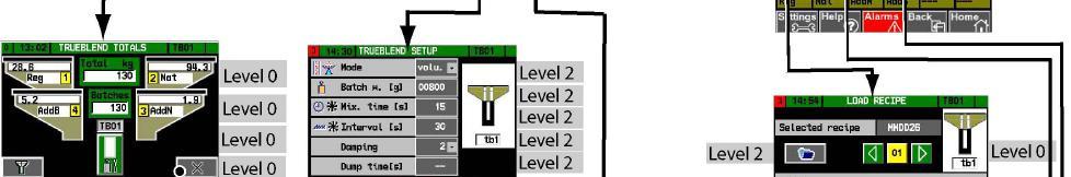


138 Appendix TrueBlend Menu overview/dosing unit 136 Edition: February 2007


139 TrueBlend Appendix Menu overview/conveying Optional Edition: February


140 Appendix TrueBlend System settings menu 138 Edition: February 2007


141 TrueBlend Appendix Unit settings menu Edition: February


142 Appendix TrueBlend Conveyor settings menu 140 Edition: February 2007
Quickstart Installation Checklist (Please refer to operation manual for complete installation instructions)
") Quickstart Installation Checklist (Please refer to operation manual for complete installation instructions) 1. Uncrate blender from packaging. 2. Lift the blender and position over machine throat or floor
Quickstart Installation Checklist (Please refer to operation manual for complete installation instructions) 1. Uncrate blender from packaging. 2. Lift the blender and position over machine throat or floor
PROPORTIONING VALVE. Model 150 INSTRUCTION MANUAL. March 2017 IMS Company Stafford Road
 PROPORTIONING VALVE Model 150 INSTRUCTION MANUAL March 2017 IMS Company 10373 Stafford Road Telephone: (440) 543-1615 Fax: (440) 543-1069 Email: sales@imscompany.com 1 Introduction IMS Company reserves
Sweeper Dual Control. Automatic Sweeper Switching System SW SERIES SWEEPERS SW-4815 SW-4820 SW-4825 MAGUIRE PRODUCTS INC.
 MAGUIRE PRODUCTS INC. SW SERIES SWEEPERS For SW Series Sweeper Models: SW-4815 SW-4820 SW-4825 Sweeper Dual Control Automatic Sweeper Switching System INSTRUCTION AND OPERATION MANUAL Copyright Maguire
MP15 Jockey Pump Controller
 Setup and Operating Instructions MP15 Jockey Pump Controller This manual provides general information, installation, operation, maintenance, and system setup information for Metron Model MP15 Jockey Pump
Misaligned Folds Paper Feed Problems Double Feeds Won t Feed FLYER Won t Run iii
 Operator s Manual Table of Contents Operator Safety... 1 Introduction... 2 Unpacking and Setup... 3 Unpacking... 3 Setup... 4 FLYER Overview... 5 FLYER Diagram... 5 Capabilities... 5 Control Panel... 6
MoveRoll Conveyor Operating and Maintenance Manual
 MoveRoll Conveyor Operating and Maintenance Manual 1. Read this first! This manual contains information for protection of personnel in the roll handling area from possible injury and/or equipment damage.
OptiAir CA09 Pneumaticfluidizing
 En Operating instructions and spare parts list OptiAir CA09 Pneumaticfluidizing unit Translation of the original operating instructions Documentation OptiAir CA09 Pneumatic-fluidizing unit Copyright 2006
OPERATOR S MANUAL SPREADER. CSS, VNQ [For Combine Harvester AW82V] Original instructions
![OPERATOR S MANUAL SPREADER. CSS, VNQ [For Combine Harvester AW82V] Original instructions](/thumbs/90/102423265.jpg "OPERATOR S MANUAL SPREADER. CSS, VNQ [For Combine Harvester AW82V] Original instructions") OPERATOR S MANUAL SPREADER CSS, VNQ [For Combine Harvester AW82V] en Original instructions Introduction Introduction Please read this operator s manual before using your spreader. We would first like to
OPERATOR S MANUAL SPREADER CSS, VNQ [For Combine Harvester AW82V] en Original instructions Introduction Introduction Please read this operator s manual before using your spreader. We would first like to
Squeegee Unit for MRS Multi-Recovery System
 En Operating Instructions Squeegee Unit for MRS Multi-Recovery System Translation of the original operating instructions Squeegee - MRS Table of Contents Safety Recommendations Technical Data - MRS Booth
ASE SOLVENT CONTROLLER INSTALLATION INSTRUCTIONS Dionex Corporation
 ASE SOLVENT CONTROLLER INSTALLATION INSTRUCTIONS 2000 Dionex Corporation Document No. 031277 Revision 03 April 2000 2000 Dionex Corporation All rights reserved worldwide. Printed in the United States of
Model 130M Pneumatic Controller
 Instruction MI 017-450 May 1978 Model 130M Pneumatic Controller Installation and Operation Manual Control Unit Controller Model 130M Controller is a pneumatic, shelf-mounted instrument with a separate
Pressure Dump Valve Service Kit for Series 3000 Units
 Instruction Sheet Pressure Dump Valve Service Kit for Series 000 Units. Overview The Nordson pressure dump valve is used to relieve hydraulic pressure instantly in Series 00, 400, 500, and 700 applicator
e.do Gripper Safety requirements, technical features and assembly and integration instructions
 e.do Gripper Safety requirements, technical features and assembly and integration instructions Requirements, technical features and instructions for safe installation and use of the e.do Gripper. CR00758190-en_00/2018.05
Pressure Automated Calibration Equipment
 GE Measurement & control Pressure Automated Calibration Equipment Safety Instructions and User Guide - K0447 PACE5000 PACE6000 K0447 Issue No. 9 1 10 1 PACE5000 1 2 3 4 5 PACE6000 2 6 7 8 3 4 5 6 7 8 9
INSTALLATION COMMISSIONING, OPERATION & MAINTENANCE MANUAL
 WedgeRock RW Series Worm Gear Actuators INSTALLATION COMMISSIONING, OPERATION & MAINTENANCE MANUAL Revision 01 Date 4/3/17 Page 1 Table of Contents 1.0 INTRODUCTION... 4 1.1 PURPOSE... 4 1.2 AUDIENCE...
Operating Instructions Part No
 DIGITAL AUTOMATIC TYRE INFLATOR Operating Instructions Part No. 11.0578 Thank you for selecting this Jamec Pem Automatic Tyre Inflator. Please read this manual before carrying out any installation or service
Touch Screen Guide. OG-1500 and OG Part # T011
 Touch Screen Guide OG-1500 and OG-2000 Part # 9000000.T011 Effective 11/2010 External View Internal View 1. Transducer Banks 2. Oxygen Sensor 3. PLC These are the two manifolds with three (3) transducers
RAM 4021 Operation Manual
 RAM 4021 Operation Manual Worldwide Manufacturer of Gas Detection Solutions TABLE OF CONTENTS RAM 4021 For your safety...3 Description...3 Set-up mode...4 Annunciator lights/alarms...4 Operation...5 Calibration...6
Gravimetric Blenders
 Gravimetric Blenders GB and WSB models with 4-component control Installation Maintenance Operation Troubleshooting Instant Access Parts and Service (800) 458-1960 (814) 437-6861 www.conairnet.com The Conair
RARS5000 AIR BODY SAW OWNER S OPERATING MANUAL
 RARS5000 AIR BODY SAW OWNER S OPERATING MANUAL DESCRIPTION 1. No mar 2. No mar tip 3. Housing grip 4. Trigger 5. Air inlet 6. Air inlet plug 7. Plastic board Important! It is essential that you read the
Pressure Dump Valve Service Kit for Series 2300 Units
 Instruction Sheet Pressure Dump Valve Service Kit for Series 00 Units. Overview The Nordson pressure dump valve is used to relieve hydraulic pressure instantly in Series 00 applicator tanks when the unit
OPERATORS MANUAL MODEL 365 BACK LAPPING MACHINE WARNING
 MODEL 365 BACK LAPPING MACHINE OPERATORS MANUAL WARNING You must thoroughly read and understand this manual before operating the equipment, paying particular attention to the Warning & Safety instructions.
icreasepro Creaser Operators Manual
 6-2013 Version 3.0 icreasepro Creaser Operators Manual WWW.MBMCORP.COM 800-223-2508 TABLE OF CONTENTS SPECIFICATIONS.1a SAFETY PROCEDURES/CARE & MAINTENANCE..1b COMPONENT IDENTIFICATION 2 TOUCH SCREEN
RAM 4021-DPX Operation Manual
 RAM 4021-DPX Operation Manual Worldwide Manufacturer of Gas Detection Solutions TABLE OF CONTENTS ABL 4021-DPX / RAM 4021-DPX For Your Safety... 3 Description... 3 Setup Mode... 4 Lights/Alarms... 4 Operation...
CLARKES ERO FEEDER MANUAL
 CLARKES ERO FEEDER MANUAL It is the sole responsibility of the Owner and/or the Responsible Supervising Operators of this equipment to properly instruct their employees, either direct or contact, in the
For parts and technical support, call your nearest Finishing Customer Support Centre. Find your nearest centre at
 Pinch Valve Assembly Customer Product Manual Issued 05/05 For parts and technical support, call your nearest Finishing Customer Support Centre. Find your nearest centre at www.nordson.com/directory This
Components for air preparation and pressure adjustment. OUT port position ( ) connected Rear side. of IN port. Air tank. directly.
 connected Rear side. of IN port. Air tank. directly.") Components preparation and pressure adjustment ABP Overview ABP is a component that enables boosting by s only up to twice primary pressure (.0MPa max.) in combination with using air tank but not using
Components preparation and pressure adjustment ABP Overview ABP is a component that enables boosting by s only up to twice primary pressure (.0MPa max.) in combination with using air tank but not using
200 PSI COMPRESSORS - MODEL NUMBERS
 200 PSI COMPRESSORS - MODEL NUMBERS 380C AIR COMPRESSOR KIT PART NO. 38033 480C AIR COMPRESSOR KIT PART NO. 48043 380C 480C IMPORTANT: It is essential that you and any other operator of this product read
444C DUAL PERFORMANCE VALUE PACK
 (Chrome) PART NO. 44432 IMPORTANT: It is essential that you and any other operator of this product read and understand the contents of this manual before installing and using this product. SAVE THIS MANUAL
IMPORTANT SAFETY INSTRUCTIONS
 IMPORTANT SAFETY INSTRUCTIONS CAUTION - To reduce risk of electrical shock: - Do not disassemble. Do not attempt repairs or modifications. Refer to qualified service agencies for all service and repairs.
RAM Operation Manual. Worldwide Manufacturer of Gas Detection Solutions
 RAM 4021 Operation Manual Worldwide Manufacturer of Gas Detection Solutions TABLE OF CONTENTS RAM 4021 For Your Safety... 2 Description.... 2 Setup Mode.... 2 Lights/Alarms.... 3 Operation.... 4 Calibration....
New AQF Filter Polymer Filtration System
 New AQF Filter Polymer Filtration System Operator Manual Covering Serial Number 20002001 onwards February 2011 Index Disclaimer notice...3 Introduction...4 Important safety notices...5 Getting started...6
Operating Instructions Part No
 DIGITAL AUTOMATIC TYRE INFLATOR Operating Instructions Part No. 11.0545 Thank you for selecting this Jamec Pem Automatic Tyre Inflator. Please read this manual before carrying out any installation or service
RAM 4021-PR. Operation Manual. Worldwide Manufacturer of Gas Detection Solutions
 RAM 4021-PR Operation Manual Worldwide Manufacturer of Gas Detection Solutions TABLE OF CONTENTS RAM 4021-PR For Your Safety... 2 Description.... 2 Setup Mode.... 2 Lights/Alarms.... 3 Operation.... 4
AIR INLINE METAL SHEAR
 AIR INLINE METAL SHEAR ASSEMBLY and OPERATING INSTRUCTIONS 3491 Mission Oaks Blvd. / Camarillo, CA 93011 Copyright 1997 by Harbor Freight Tools. All rights reserved. No portion of this manual or any artwork
TECHNICAL INFORMATION SPECIFICATIONS FEATURES. Maguire Products Inc 11 Crozerville Road Aston, PA WEIGH SCALE BLENDER SEPTEMBER 04, 2012
 Maguire Products Inc 11 Crozerville Road Aston, PA. 610-459-4300 WEIGH SCALE BLENDER SEPTEMBER 04, 2012 TECHNICAL INFORMATION SPECIFICATIONS FEATURES TECHNICAL INFORMATION SPECIFICATIONS FEATURES COPYRIGHT
ATD LB PRESSURE BLASTER INSTRUCTION MANUAL
 ATD-8402 90LB PRESSURE BLASTER INSTRUCTION MANUAL SAVE THESE INSTRUCTIONS SAFETY INSTRUCTIONS FOR SANDBLASTER 1. Before opening the tank release the air pressure on the sand tank. To do this, turn off
1 DRIVE INDUSTRIAL IMPACT WRENCH
 1 DRIVE INDUSTRIAL IMPACT WRENCH 92622 ASSEMBLY AND OPERATING INSTRUCTIONS 3491 Mission Oaks Blvd., Camarillo, CA 93011 Visit our Web site at http://www.harborfreight.com Copyright 2004 by Harbor Freight
O P E R ATING INSTRUCTIONS FOR MODEL SPR-45 Automatic Screen and Stencil Printer
 O P E R ATING INSTRUCTIONS FOR MODEL SPR-45 Automatic Screen and Stencil Printer TABLE OF CONTENTS I. SPECIFICATIONS...3. II. SAFETY INSTRUCTIONS...4. III. INSTALLATION...5. IV. SET-UP...6. V. SYSTEM OPERATION...9.
Pressure maintenance valve SDV-P / SDV-P-E
 Translation of the original manual Pressure maintenance valve SDV-P / SDV-P-E Assembly and Operating Manual Superior Clamping and Gripping Imprint Imprint Copyright: This manual remains the copyrighted
USER MANUAL. MACMAG magnetic separator MHK MHF
 USER MANUAL MACMAG magnetic separator MHK MHF Important Read the safety precautions before use. Thank you for your purchase. This user manual contains important information on avoiding damage and personal
100C Air Compressor Kit
 10010 100C Air Compressor (standard mounting bracket, CE Spec) 10014 100C Air Compressor (no leader hose or check valve, CE Spec) 10016 100C Air Compressor (with Omega Bracket, CE Spec) IMPORTANT: It is
OPERATING INSTRUCTIONS MANUAL FOR QACV PNEUMATIC DOSING PUMP
 This operating instructions contains safety information that if ignored can endanger life or result in serious injury. They are indicated by this icon. Use of this pump with radioactive chemicals is forbidden!
Operation Manual Air Saver Unit ASV5000 Series
 9IM-V066-b Operation Manual Air Saver Unit ASV5000 Series Thank you for your choice of Kuroda Pneumatics LTDs product on this time. Please read this operation manual carefully and use the product correctly.
In Vessel Composter Installation & Commissioning Manual
 In Vessel Composter Installation & Commissioning Manual Contents Customer responsibilities Transportation Lifting Delivery Pre-installation requirements Installation Drainage Ventilation Levelling Unpacking
420C AIR COMPRESSOR KIT PART NO C AIR COMPRESSOR KIT PART NO
 420C AIR COMPRESSOR KIT PART NO. 42042 460C AIR COMPRESSOR KIT PART NO. 46043 420C 460C IMPORTANT: It is essential that you and any other operator of this product read and understand the contents of this
GROUTEC SCOTT VICKERS. Grouting Equipment
 GROUTEC SCOTT VICKERS Grouting Equipment SCOTT VICKERS manufacturers a range of cement and chemical grouting equipment including:- PUMPS - The Cement Grout Pumps are all diaphragm-type. These diaphragms,
OPERATION and MAINTENANCE Guide
 Catalog No. AIR1000 Winch and Hoist OPERATION and MAINTENANCE Guide Cat. No. AIR1000 1250 Lb. Single Line Pull READ THIS BEFORE OPERATING UNIT INSTALLATION: Mount on clean, flat surface. Use 1/2" mounting
400C & 450C DUAL PERFORMANCE VALUE PACKS
 (Chrome) PART NO. 40013 (Silver) PART NO. 45012 (Chrome) PART NO. 45013 IMPORTANT: It is essential that you and any other operator of this product read and understand the contents of this manual before
SPECIFICATIONS ATTENTION
 VPS 504 S06 Installation Manual - P/N 80122 - Ed. 01/09 VPS 504 S06 and S05 Valve Proving System Installation Instructions VPS 1 6 Gases Natural gas, air and other inert gases. NOT suitable for butane
MANUAL DIRECT PURGE OPTION. UNION Instruments GmbH CWD2005 PLUS. General information, safety standards and regulations for direct purge option
 MANUAL DIRECT PURGE OPTION UNION Instruments GmbH CWD2005 PLUS General information, safety standards and regulations for direct purge option Version: V1.00 Stand: 24.03.2010 Union Instruments GmbH Zeppelinstr.
RAM Operation Manual. Worldwide Manufacturer of Gas Detection Solutions
 RAM 4021 Operation Manual Worldwide Manufacturer of Gas Detection Solutions TABLE OF CONTENTS RAM 4021 For Your Safety... 2 Description.... 2 Setup Mode.... 2 Lights/Alarms.... 3 Operation.... 4 Calibration....
INTENDED USE TECHNICAL SPECIFICATIONS
 1/2IN. HEAVY-DUTY AIR IMPACT WRENCH OWNER S MANUAL WARNING: Read carefully and understand all INSTRUCTIONS before operating. Failure to follow the safety rules and other basic safety precautions may result
Pontoon Slide Owner s Manual
 Pontoon Slide Owner s Manual WWW.RAVESPORTS.COM Copyright 2018 All rights reserved. No part of this publication may be reproduced or transmitted in any form or by any means, electronic or mechanical, including
General Information. NTA607HD Lift Assist Adjustments. Tools Required. Work Location. Notations and Conventions U B F D R B F L
 Great Plains Manufacturing, Inc. 1 NTA607HD Lift Assist Adjustments Null4: When you see this symbol, the subsequent instructions and warnings are serious - follow without exception. Your life and the lives
250C-IG COMPRESSOR KIT 12V PART NO C-IG COMPRESSOR KIT 24V PART NO
 250C-IG COMPRESSOR KIT 12V PART NO. 25050 250C-IG COMPRESSOR KIT 24V PART NO. 25058 IMPORTANT: It is essential that you and any other operator of this product read and understand the contents of this manual
Safety instructions and operating manual
 5-Master Safety instructions and operating manual TBF-PyroTec GmbH Lichterfelder Str. 5 A 21502 Geesthacht Tel.: + 49 (0)4152 157 9950 Fax: + 49 (0)4152 157 9951 Flame projector 5-Master Safety instructions
User Manual 1 P a g e Rev. V1.6-EN 11/08/2014
 User Manual 1 P a g e Rev. V1.6-EN 11/08/2014 Copyright Disclaimer Trademarks and patents Intended use Contact info 2011 Inflotrolix, Inc. This document may not be copied in whole or in part or otherwise
97C COMPRESSOR KIT 12V PART NO C COMPRESSOR KIT 24V PART NO C COMPRESSOR KIT PART NO
 97C COMPRESSOR KIT 12V PART NO. 00097 97C COMPRESSOR KIT 24V PART NO. 02497 98C COMPRESSOR KIT PART NO. 00098 97C 98C IMPORTANT: It is essential that you and any other operator of this product read and
Pontoon Slide Owner s Manual
 Pontoon Slide Owner s Manual www.ravesports.com Table of Contents Introduction... 2 Safety rules and information... 3 Boat compatibility guide.5 Assembling and using your Pontoon Slide... 6 Cleaning and
SPECIFICATIONS APCEPH1
 APCEPH1 ph CONTROLLER SPECIFICATIONS APCEPH1 Input voltage 120 Volts AC Maximum amperage 14.5 amps @ 120 VAC ph Accuracy +/- 0.2 ph ph Control range Adjustable 4.5 8.5 ph Weight < 1 lbs Dimensions 3" x
Installation and operating manual. Pneumatic control station LK product no: PCS 1-10
 LK product no: PCS 1-10 Article no: 74503 Revision:8 Article no: 74503 Revision: 8 2 (23) Contents 1. General information... 5 2. Safety precautions... 5 2.1 Significance of symbols... 5 2.2 Explanatory
SG36KTL-M Quick Installation Guide. 1 Unpacking and Inspection
 SG36KTL-M Quick Installation Guide This guide provides a general instruction of the installation procedures of SG36KTL-M. In no case shall this guide substitute for the user manual or related notes on
NB/NBR NITROGEN BOOSTER FOR AVIATION SERVICE
 NB/NBR NITROGEN BOOSTER FOR AVIATION SERVICE INSTALLATION, OPERATION & MAINTENANCE MANUAL INTERFACE DEVICES, INC. 230 Depot Road, Milford, CT 06460 Ph: (203) 878-4648, Fx: (203) 882-0885, E-mail: info@interfacedevices.com
Operating and maintenance manual Filter and reducing station Series / 1.0
 Operating and maintenance manual Filter and reducing station Series 961 04.2017 / 1.0 Original instructions ARCA Regler GmbH. All rights reserved. Cover picture background: Freepik.com ARCA Regler GmbH
Pneumatic blending in a bin or silo that is, aerating. Saving time, labor, and money with pneumatic batch blending. Copyright CSC Publishing
 As appeared in January 2013 PBE Copyright CSC Publishing www.powderbulk.com Saving time, labor, and money with pneumatic batch blending Mike Weyandt Nol-Tec Systems With a pneumatic blender, you can mix
In Vivo Scientific, LLC INSTRUCTION MANUAL
 CO 2 Controller In Vivo Scientific, LLC INSTRUCTION MANUAL CONTENTS CONTENTS...1 ABOUT THIS MANUAL...2 INTRODUCTION...2 Cautions and Warnings...2 Parts List...2 Unpacking...2 INSTRUMENT DESCRIPTION...3
UltraLo 1800 Alpha Particle Counter
 XIA LLC UltraLo 1800 Alpha Particle Counter Site Requirements & Planning Version: 0.4 Friday, February 15, 2013 Table of Contents I. Site Preparation Tasks... 3 A. Instrument Overview... 3 B. Installation
Contents. Operating instructions. Pressure switch, heavy-duty version Model PSM-520
 Operating instructions Contents EN Pressure switch, heavy-duty version Model PSM-520 1. General information 2. Design and function 3. Safety 4. Transport, packaging and storage 5. Commissioning, operation
Lockout. HealthandSafetyOntario.ca. What is Lockout? How is a Lockout Done? Why is a Lockout Necessary?
 What is Lockout? Lockout means to physically neutralize all energies in a piece of equipment before beginning any maintenance or repair work. Lockouts generally involve: Stopping all energy flows (for
UBEC 1AT. AUTO TANK Fill System Installation, Operation, & Setup Instructions
 Document Number: XE-ATA5PM-R1A UBEC 1AT AUTO TANK Fill System 08899155 Installation, Operation, & Setup Instructions Rev170906-EB-FRC PHYSICAL: 1302 WEST BEARDSLEY AVE ELKHART, IN 46514 WWW.ELKHARTBRASS.COM
DBML-60/80 Squeeze Tool
 DBML-60/80 Squeeze Tool OPERATORS MANUAL Description The Mustang Model DBML-60/80 Hydraulic squeeze tool has been manufactured since 1995. A Mustang 3 3/4 bore doubleacting cylinder producing 41,000 lbs
30T A/Manual Hydraulic Shop Press
 30T A/Manual Hydraulic Shop Press Operation Manual 1 1. Important Information 1.1 Safety Information 1.1.1 Hazard Symbols Used in the Manuals This manual includes the hazard symbols defined below when
INSTRUCTION MANUAL FOR MODEL 7360V VERTICAL CURING CHAMBER Revision E May
 INSTRUCTION MANUAL FOR MODEL 7360V VERTICAL CURING CHAMBER Revision E May 2015 98-0520 S/N 2001 N. Indianwood Ave. Tulsa, Oklahoma 74012 U.S.A. TEL: (918) 250-7200 FAX: (918) 459-0165 E-mail: chandler.sales@ametek.com
September 10, 2014 Revision 2. Puncher Unit-BE1/BF1/BG1/BH1 Service Manual
 1 4 September 10, 014 Revision Puncher Unit-BE1/BF1/BG1/BH1 Service Manual 0 0- Application This manual has been issued by Canon Inc. for qualified persons to learn technical theory, installation, maintenance,
Related Products: Auto Drain Valve. Model/Specifications. Model
 Related Products: Auto Drain Valve /600 Drainage is automatically discharged in a reliable manner, without requiring human operators. Highly resistant to dust and corrosion, operates reliably, and a bowl
Installation, Operating & Maintenance Instructions. Variable leak valve with manual actuator. Series 590 DN 16 mm (I. D. ⅝") E
 E") Installation, Operating & Maintenance Instructions Variable leak valve with manual actuator DN 16 mm (I. D. ⅝") This manual is valid for the following product ordering numbers: 59024-. E01 -... Sample
Installation, Operating & Maintenance Instructions Variable leak valve with manual actuator DN 16 mm (I. D. ⅝") This manual is valid for the following product ordering numbers: 59024-. E01 -... Sample
AUTOMATIC FILM APPLICATOR MICROPROCESSOR CONTROLLED. Operating Instructions for the
 TQC AUTOMATIC FILM APPLICATOR AB3120, AB3220, AB3320, AB3125, AB3225, AB3325 IMPORTANT! Before taking this instrument in use we strongly advise you to read this manual carefully. Operating Instructions
User Manual. Quantos Automated Dosing Liquid Module
 User Manual Liquid Module 1 Safety Information 1.1 Definition of warnings and symbols Signal Words WARNING for a hazardous situation with medium risk, possibly resulting in severe injuries or death if
RAM Operation Manual
 RAM 4021-1 Operation Manual Worldwide Manufacturer of Gas Detection Solutions TABLE OF CONTENTS RAM 4021-1 For Your Safety... 2 Description... 2 Setup Mode... 3 Lights/Alarms... 3 Operation... 4 Calibration...
Pneumatic blending in a bin or silo that is, aerating. Saving time, labor, and money with pneumatic batch blending
 As appeared in January 2013 PBE www.powderbulk.com Saving time, labor, and money with pneumatic batch blending Mike Weyandt Nol-Tec Systems With a pneumatic blender, you can mix batches of dry bulk materials
Installation, operating and maintenance Instructions for Seemag bypass level indicator
 Issue: S Date: 05-09-14 Type G35 General information The Seetru bypass magnetic level indicator, abbreviate SEEMAG, serves to show the filling level of fluids in tanks, basins, tubes etc. The Seemag operates
GI Series Diaphragm Pressure Gauge Guard
 Diaphragm Pressure Gauge Guard INSTRUCTION MANUAL Please read this Instruction Manual Carefully and Thoroughly for the Correct and Optimum use of this Product. Kindly keep this manual in a convenient place
RGC-IR Remote Gas Calibrator for IR400
 Remote Gas Calibrator for IR400 The information and technical data disclosed in this document may be used and disseminated only for the purposes and to the extent specifically authorized in writing by
AUTOMATIC TIRE INFLATOR # MW-60, MW-60-4WAY & MW-64HP
 USER MANUEL AUTOMATIC TIRE INFLATOR # MW-60, MW-60-4WAY & MW-64HP TIRE EQUIPMENT MANUFACTURER 1.866.409.RACK WWW.MARTINSINDUSTRIES.COM info@martinsindustries.com PARTS Verify that the following components
accidents which arise due to non-observance of these instructions and the safety information herein. SPECIFICATIONS
 18 GAUGE 1-1/4 INCH BRAD NAILER Model: 7611 CALIFORNIA PROPOSITION 65 WARNING: You can create dust when you cut, sand, drill or grind materials such as wood, paint, metal, concrete, cement, or other masonry.
Pneumatic Controls, Air Settings, Hydraulic adjustments on; Models 22HF, 16HF & 1600 machines
 Knowledge Base Article Type: Instructions Pneumatic Controls, Air Settings, Hydraulic adjustments on; Models 22HF, 16HF & 1600 machines Description: Instruction sheet on how to make proper pneumatic air
E L E V E N C R O Z E R V I L L E R D. A S T O N, P A WEIGH SCALE BLENDER with "FOUR" COMPONENT SOFTWARE SEPTEMBER 26, 2013
 M A G U I R E P R O D U C T S, I N C. M A G U I R E P R O D U C T S, I N C. M A G U I R E P R O D U C T S, I N C. M A G U I R E P R O D U C T S, I N C. M A G U I R E P R O D U C T S, I N C. M A G U I R
ECHO MANUAL WARNING. L B A ltim e te rs. ECHO is a trademark of LB Altimeters, Denmark
 ECHO MANUAL L B A ltim e te rs ECHO is a trademark of LB Altimeters, Denmark LB Altimeters operates a policy of continuous development Therefore, we reserve the right to make changes and improvements to
250C-IG COMPRESSOR KIT 12V PART NO C-IG COMPRESSOR KIT 24V PART NO
 250C-IG COMPRESSOR KIT 12V PART NO. 25050 250C-IG COMPRESSOR KIT 24V PART NO. 25058 IMPORTANT: It is essential that you and any other operator of this product read and understand the contents of this manual
IMPORTANT CO2/ HPA AIR TANK SAFETY INSTRUCTION AND GUIDELINES. Tank valves must be installed or removed by qualified personnel.
 !WARNING! IMPORTANT SAFETY INSTRUCTION AND GUIDELINS!WARNING! IMPORTANT CO2/ HPA AIR TANK SAFETY INSTRUCTION AND GUIDELINES GETTING STARTED This Paintball Marker is NOT A TOY. Misuse can cause serious
ORB-400 BUBBLE/HAZE MACHINE. Item ref: UK User Manual
 ORB-400 BUBBLE/HAZE MACHINE Item ref: 160.462UK User Manual Caution: Please read this manual carefully before operating Damage caused by misuse is not covered by the warranty Introduction Thank you for
SPECIFICATIONS Type: Twin stack, single phase Tank: 4 gallon Air Output: PSI; PSI Max PSI: 125 PSI HP: 1.
 2 GALLON TWIN STACK AIR COMPRESSOR Model: 9526 DO NOT RETURN TO STORE. Please CALL 800-348-5004 for parts and service. CALIFORNIA PROPOSITION 65 WARNING: You can create dust when you cut, sand, drill or
Stone Container 987 Auger Packer Manual
 Stone Container 987 Auger Packer Manual SAFETY INSTALLATION OPERATION MAINTENANCE, Ltd. (512) 352-3694 Phone (512) 352-3648 Fax 1 Table of Contents Topic Reconditioned Machine Information Page Insert Chapter
Installation Instructions, Pressure Regulator Series
 Installation Instructions, Pressure Regulator 20517 Series Manual Model: 20517, L20517 Air motor Operated: F20517, LF20517 Hydraulic Motor Operated: G20517, LG20517 1. GENERAL ------------------------------------------------------------------------------
USER MANUAL SAVE THESE INSTRUCTIONS. For the most current manual revision, please visit our Website:
 USER MANUAL Model: PM4300 Series SAVE THESE INSTRUCTIONS For the most current manual revision, please visit our Website: www.precisionmedical.com 300 Held Drive Tel: (+001) 610-262-6090 Northampton, PA
Inventory Monitor Units Red-Lion Display. Models: OI, SIT, CIT
 Inventory Monitor Units Red-Lion Display Models: OI, SIT, CIT Part Number: 882.02323.00 Bulletin Number: BLN1-620 Effective: February 1, 2013 an company Write Down Your Serial and Software Revision Numbers
Safety Powder Spray Systems
 Instruction Sheet P/N 107 952C Safety Powder Spray Systems 1. Introduction This section contains general safety instructions for using your Nordson equipment. Task- and equipment-specific warnings are
HAI UPB 15A Relay Switch and Auxiliary Switch Installation and Operating Instructions
 HAI UPB 15A Relay Switch and Auxiliary Switch Installation and Operating Instructions For the following Models: 40A00-1 HAI 15A Relay Switch (referred to as HAI UPB Wall Switch, in this document), and
Pneumatic high-pressure controller Model CPC7000
 Calibration technology Pneumatic high-pressure controller Model CPC7000 WIKA data sheet CT 27.63 Applications Healthcare and avionics industry Industry (laboratory, workshop and production) Transmitter