THE PETROLEUM INDUSTRY Code of Practice
|
|
|
- Christopher George
- 5 years ago
- Views:
Transcription
1 DZS 385 Part 2 : 2015 ICS ; SECOND EDITION Draft for Public comment ZAMBIAN STANDARD THE PETROLEUM INDUSTRY Code of Practice Part 2: Electrical installations in the distribution and marketing sector This draft standard is for public enquiry only. It must not be used or referred to as a Zambian Standard. ZAMBIA BUREAU OF STANDARDS
2 Amendments issued since publications Amdt No. Date Text affected COPYRIGHT PROTECTED DOCUMENT ZABS 2015 All rights reserved. Unless otherwise specified, no part of this publication may be reproduced or utilized in any form or by any means, electronic or mechanical, including photocopying and microfilm, without permission in writing from Zambia Bureau of Standards
3 DATE OF PUBLICATION This Zambian Standard has been prepared and published under the authority of the Standards Council of the Zambia Bureau of Standards on... ZAMBIA BUREAU OF STANDARDS The Zambia Bureau of Standards is a statutory organization established by the Zambia Bureau of Standards Act, Cap 416 of the Laws of Zambia for the preparation and promulgation of Zambian Standards. REVISION OF ZAMBIAN STANDARDS Zambian Standards are revised, when necessary, by the issue either of amendments or of revised editions. It is important that users of Zambian Standards should ascertain that they are in possession of the latest amendments or editions. CONTRACT REQUIREMENTS A Zambian Standard does not purport to include all the necessary provisions of a contract. Users of Zambian Standards are responsible for their correct application. TECHNICAL COMMITTEE RESPONSIBLE This Zambian Standard was prepared by the Technical Committee TC 2/14 Petroleum Storage Installation upon which the following organizations were represented: DH Engineering Energy Regulation Board Engineering Institution of Zambia Indeni Petroleum Refinery Limited Ministry of Local Government and Housing Ministry of Mines Energy and Water Development Mount Meru Petroleum (Z) Limited Total Zambia Limited Zambia Bureau of Standards Zambia Environmental Management Agency Zambia Weights and Measures Agency ZAMBIA BUREAU OF STANDARDS, P.O. BOX 50259, ZA 15101, RIDGEWAY, LUSAKA 1 All rights reserved
4 Table of Contents FOREWORD SCOPE NORMATIVE REFERENCES DEFINITIONS CLASSIFICATION OF HAZARDOUS LOCATIONS GENERAL ZONE 0, ZONE 1 AND ZONE 2 LOCATIONS CERTIFICATION REQUIREMENTS FOR EXPLOSION-PROTECTED APPARATUS SELECTION OF EXPLOSION-PROTECTED APPARATUS SELECTION CRITERIA SELECTION OF APPARATUS INSTALLATION, MAINTENANCE, INSPECTION AND REPAIR CATHODIC PROTECTION GENERAL PROTECTION REQUIREMENTS FOR EARTHING AND BONDING ELECTRICAL SAFETY EARTH LIGHTNING PROTECTION SINGLE SYSTEM STORAGE TANKS STATIC ELECTRICITY AND BONDING STRAY CURRENTS AND ISOLATING FLANGES INSTRUMENTATION SYSTEMS SIDINGS ANNEX A All rights reserved
5 FOREWORD The Zambia Bureau of Standards (ZABS) is the Statutory Organization established by an Act of Parliament. ZABS is responsible for the preparation of national standards through its various Technical committees composed of representation from government departments, the industry, academia, regulators, consumer associations and nongovernmental organizations. This National standard has been prepared in accordance with the procedures of the ZABS. All users should ensure that they have the latest edition of this publication as standards are revised from time to time. No liability shall attach to ZABS or its Director, employees, servants or agents including individual experts and members of its Technical Committees for any personal injury, property damage or other damages of any nature whatsoever, whether direct or indirect, or for costs (Including legal fees) and expenses arising out of the publication, use of, or reliance upon this ZABS publication or any other ZABS publication. Compliance with a Zambian standard does not of itself confer immunity from legal obligations. DZS 385 Part 1: 2015 was prepared by the Technical Committee TC 2/14 Petroleum Storage Installation ZS 385 consists of the following parts under the general title the petroleum industry. 1. Part 1: Storage and distribution of petroleum products in above-ground bulk installations. 2. Part 2: Electrical installations in the distribution and marketing sector. 3. Part 3: The installation of underground storage tanks, pumps/dispensers and pipework at service stations and consumer installations. This Part of ZS 385 was based on SANS , The Petroleum Industry - Code of Practice - Part 1: Storage and distribution of petroleum products in above-ground bulk installations. 3 All rights reserved
6 ZAMBIAN STANDARD THE PETROLEUM INDUSTRY Code of Practice Part 2: Electrical installations in the distribution and marketing sector 1. SCOPE This part of ZS 385 covers the recommended safe practice in the design, construction, installation and maintenance of electrical and earthing and bonding systems intended to be used in flammable and combustible liquid storage, pumping, distribution and marketing facilities. It is not intended that this code should apply to refineries or exploration facilities, unless any of these installations are similar to such facilities as those listed above. This standard does not cover the requirements for flammable dust. 2. NORMATIVE REFERENCES The following standards contain provisions which, through reference in this text, constitute provisions of this part of ZS 385. All standards are subject to revision and, since any reference to a standard is deemed to be a reference to the latest edition of that standard, parties to agreements based on this part of ZS 385 are encouraged to take steps to ensure the use of the most recent editions of the standards indicated below. Information on currently valid national and international standards can be obtained from the Zambia Bureau of Standards. API RP 500 API Std 610 API RP 2003 ZS IEC ZS IEC IP Code part 15 Recommended practice for classification of locations for electrical installations at petroleum facilities classified as Class I, Division 1 and Division 2. Centrifugal pumps for petroleum, heavy duty chemical and gas industry services. Protection against ignitions arising out of static, lightning and stray currents. Electrical apparatus for explosive gas atmospheres - Part 10: Classification of hazardous areas. Electrical apparatus for explosive gas atmospheres- Part 11: Intrinsic safety "i". The Institute of Petroleum Model Code of Safe Practice in the Petroleum Industry - Part 15: Area classification code for petroleum installations. IP Code part 21 The Institute of Petroleum Model Code of Safe Practice in the Petroleum Industry - Part 21: Guidelines for the control of hazards arising from static electricity. ZS 429 ZS IEC ZS ZS 791 ZS The handling, storage and distribution of liquefied petroleum gas in domestic, commercial and industrial installations code of practice Explosive atmospheres - Part 17: Electrical installations inspection and maintenance Lightning protection standard The wiring of premises. The petroleum industry Part l: Storage and distribution of petroleum products in above- ground bulk installations. 4 All rights reserved
7 ZS The petroleum industry - Part 3: The installation of underground storage tanks, pumps/dispensers and pipework at service stations and consumer installations. ZS DEFINITIONS The classification of hazardous locations and the selection of apparatus for use in such locations. For the purpose of this part of ZS 385 the following definitions apply: 3.1 approved standard A standard (a code of practice, a specification or a test method) that has been approved by the approving authority (see 3.3) in terms of the relevant statutory regulations 3.2 approved testing/certification body A testing laboratory that is equipped to carry out the tests specified in the appropriate standards and whose certificates are acceptable to the appropriate approving authority (see 3.3) 3.3 approving authority Within the scope of the Factories Act, Cap 441 of the Laws of Zambia: the Chief Inspector Within the scope of the Energy Regulation Act, Cap 436 of the Laws of Zambia, the Board 3.4 bonding a low impedance connection, usually less than 2 Ohm 3.5 cathodic protection a technique for mitigating corrosion attack on a metal by making it the cathode in the electrolitic environment, by using as anode another metal that will preferentially be corroded 3.6 combustible liquid a liquid that has a closed-cup flash point at or above 38ºC. For the purpose of this part of ZS 385, combustible liquids shall be subdivided as follows: Class II: liquids that have a closed-cup flash point at or above 38ºC and below 60.5ºC. Class IIIA: liquids that have a closed-cup flash point at or above 60.5ºC and below 93ºC. Class IIIB: liquids that have a closed-cup flash point at or above 93ºC. NOTE If class II and class III combustible liquids are stored or handled at temperatures at or above their flash points, then special precautions shall be taken in both the layout and the operation for such liquids. 3.7 encapsulated electrical apparatus Ex m apparatus electrical apparatus in which parts that could ignite an explosive atmosphere are so enclosed in a compound that this explosive atmosphere cannot be ignited 3.8 enclosed premises a building, a room or an enclosed space that is not substantially open to the outside air and through which there is no free and natural passage for air NOTE Any space that has more than a roof and one solid wall or is surrounded by other buildings or structures in such a way as to obstruct quick dissipation of any released gases or vapours should be considered to be enclosed. 5 All rights reserved
8 3.9 explosion protected electrical apparatus designed and approved for use in hazardous areas in accordance with a suitable protection method, including Ex d, Ex ia, Ex ib, Ex e, Ex p, Ex n, Ex s, Ex m, Ex q or a combination of these methods 3.10 flameproof apparatus Ex d apparatus apparatus in which parts of the apparatus that can ignite an explosive atmosphere are placed in an enclosure that can withstand the pressure developed during an internal explosion of an explosive mixture and that prevents the transmission of the explosion to the explosive atmosphere surrounding the enclosure 3.11 flammable liquid a liquid with a flash point below 38ºC, regardless of its temperature, or a liquid with a flash point at or above 38ºC being handled at temperatures at or above its flash point NOTE Classes of petroleum are defined in ZS as follows and apply to this part of ZS 385: Petroleum products are classified according to their physical properties. Product classifications vary between different codes of practice. The following classification applies to the requirements listed in this part of ZS 385: Class 0. Liquefied Petroleum Gases (LPG) Class I. Liquids that have flash points below 21 C. Class II (1). Liquids that have flash points from 21 C up to and including 55 C, handled below flash point. Class II (2). Liquids that have flash points from 21 C up to and including 55 C, handled at or above flash point. Class III (1). Liquids that have flash points above 55 C up to and including 100 C, handled below flash point. Class III (2). Liquids that have flash points above 55 C up to and including 100 C, handled at or above flash point. Unclassified. Liquids that have flash points above 100 C grade of release of flammable gasses, liquids or vapours continuous release a release that is likely to occur continuously in normal operation primary release a release that is likely to occur periodically or occasionally in normal operation. (As a rough rule of thumb for a continuously operating plant, a release likely to be present for more than 10 but less than 1000 hours per year should be regarded as primary.) secondary release a release that is unlikely to occur in normal operation and, in any event, will occur infrequently and be of short duration. (As a rough rule of thumb for a continuously operating plant, a release likely to be present for less than 10 hours per year and for short periods only should be regarded as secondary.) 3.13 hazardous location area any three-dimensional region at a facility where there could be a risk of the ignition of a flammable gas, vapour or any other explosive material 3.14 hydraulic housing housing which provides physical protection to the liquid or the vapour equipment (or both) 6 All rights reserved
9 3.15 increased safety electrical apparatus Ex e apparatus electrical apparatus in which measures are applied to prevent, with a minor degree of security, the possibility of excessive temperatures and of the occurrence of arcs or sparks in the interior and on the external parts of an electrical apparatus that does not produce them in normal service 3.16 intrinsically safe circuit Ex i circuit a circuit in which any spark, arc or thermal effect, whether produced normally (i.e. by breaking or closing of the circuit) or accidentally (for example, by a short circuit or an earth fault), is incapable, under prescribed test conditions, of causing ignition of a prescribed gas or vapour 3.17 intrinsically safe electrical apparatus Ex i apparatus electrical apparatus that is suitable for use in a hazardous location and in which all the circuits are intrinsically safe, or electrical apparatus that is designed to form part of an intrinsically safe system 3.18 intrinsically safe electrical apparatus of categories "ia" and "ib" electrical apparatus that, when tested in accordance with ZS IEC , is incapable of causing ignitions under hazardous conditions 3.19 intrinsically safe system Ex i system a system that is certified by an approved testing/certification body and that comprises electrical apparatus and interconnecting wiring in which any spark or thermal effect in any part of the system intended for use in a hazardous location is incapable, under prescribed test conditions, of causing ignition of a prescribed gas or vapour NOTE An intrinsically safe system is also incapable of igniting atmospheres that contain prescribed flammable dusts or fibres non-sparking electrical apparatus Ex n apparatus electrical apparatus that, in normal operation and in the absence of electrical and mechanical failure, cannot, because of its construction, method of operation or its enclosure, ignite mixtures of air and prescribed flammable gases or vapours 3.21 open premises any space that is substantially open and offers no obstruction to the free and natural passage of air through it. Such premises may be roofed for weather protection or enclosed, for example, in wire mesh or expanded metal or louvres or open block construction, provided that adequate ventilation exists and the roof and side enclosures do not at any point materially obstruct the free passage of air to and through any point of the space 3.22 powder-filled or sand-filled electrical apparatus Ex q apparatus electrical apparatus of which the enclosure is so filled with a material in a finely granulated state that any arc occurring within the enclosure will not ignite the surrounding atmosphere, and ignition will not be caused either by flame or excessive temperature of the surfaces of the enclosure 3.23 pressurised electrical apparatus Ex p apparatus electrical apparatus in which the entry of a surrounding atmosphere into the enclosure of the electrical apparatus is prevented by maintaining, inside the said enclosure, a protective inert gas or fresh air at a higher pressure than that of the surrounding atmosphere. The overpressure is maintained either with or without a continuous flow of the protective inert gas or fresh air 7 All rights reserved
10 3.24 vapour barrier A sealing system that is used to limit the passage of hazardous gasses or vapours 4. CLASSIFICATION OF HAZARDOUS LOCATIONS 4.1 General The basic principles of area classification owing to the presence of flammable gases or liquids are listed in to Reference can be made to ZS 402, ZS IEC , IP Code Part 15 or API RP 500 for more detailed information. NOTE It is recommended that the extent of hazardous areas be demarcated and recorded, at least on a drawing but if possible also by floor marking. For practical purposes only distances in the horizontal plane need to be drawn and the extent of the vertical distances can be indicated in writing. Identify the sources of release of flammable gases, liquids and vapours. Identify the sources of release of class II and class IIIA combustible liquids at a temperature at or above their flash points, or released as a fine mist or spray. Such sources will give rise to a hazardous area. NOTE Where a class IIIB combustible liquid is stored or handled an assessment is required to determine if such a liquid will give rise to a hazardous area at the various sources of release. Divide the hazardous area into zones according to the grade of release (determined by the frequency with which a flammable atmosphere occurs and its duration). See clause 4.2. Ventilation could serve to reduce the extent of a hazardous area as discussed in (c) below, or could so affect the duration of the flammable atmosphere that a reduced zone can be allocated. Calculate the extent of a hazard zone by reason of the rate of release and the nature of the flammable substance, which is mainly defined by the process pressure and temperature, the liquid flash point and boiling point, the density of the released vapour or gas, and the rate at which it is diluted (ventilated). Allocate the appropriate equipment group and temperature class (or maximum surface temperature), pertaining to the use of explosion-protected apparatus in the hazardous area. Where a mixture of flammable gases or flammable vapours (or both) occurs, the worst-case values shall be specified, unless the mixture is of controlled composition and has well-defined ignition properties. Practical area classification is simplified if classification by direct example is applied. Such examples are given in annexes A and B of this part of ZS 385. These examples apply to the oil industry distribution and marketing standards as given in ZS and ZS 385-3, respectively, and when the examples are applied, the facility under consideration must not differ significantly from the given example in terms of layout, type of equipment, class of petroleum product or the conditions of temperature or ventilation state. NOTE: Locations that have been classified in accordance with ZS IEC , the British Institute of Petroleum's Model Code of Safe Practice, Part 15, the American Petroleum Institute's recommended practice 500, or other approved standards should be considered to have been classified in accordance with this standard. 4.2 Zone 0, Zone 1 And Zone 2 Locations Zone 0, zone 1 or zone 2 locations are those in which flammable gases or vapours can be present in the air in quantities sufficient to become hazardous Zone 0 locations Zone 0 locations are those in which flammable gases or vapours are continuously or very frequently present. NOTE 1 A continuous grade of release normally leads to a zone 0 location. 8 All rights reserved
11 NOTE 2 Such a condition is rarely encountered and is limited mainly to confined spaces (such as the vapour space of closed process vessels, closed storage tanks, and closed containers), although it can also occur in larger rooms, such as rooms in chemical plants. Even in such spaces it is possible that the gas-air or the vapour-air mixture is normally outside the flammability range Zone 1 locations Zone 1 locations are those in which: a) hazardous concentrations of flammable gases or vapours occur intermittently or periodically under normal operating conditions; or b) hazardous concentrations of flammable gases or vapours can occur frequently because of repair or maintenance operations or because of leakage (which may be the result of inadequate equipment maintenance); or c) breakdown or faulty operation of equipment or processes can occur, which might cause the release of hazardous concentrations of flammable gases or vapours, while also causing simultaneous failure of electrical equipment; or d) channels or sumps in a zone 2 area to be classified as zone 1. NOTE 1 A primary grade of release normally leads to a zone 1 location. NOTE 2 This classification usually includes locations where volatile flammable liquids or liquefied flammable gases are transferred from one container to another; interiors of spray booths and areas in the vicinity of spraying and painting operations where flammable solvents are used; locations that contain open tanks or vats of flammable liquids; oil extraction apparatus that uses flammable solvents, portions of cleaning and drying plants where flammable liquids are used; inadequately ventilated pump rooms for flammable gases or for flammable liquids and all other locations where hazardous concentrations of flammable vapours or gases can occur in the course of normal operations. NOTE 3 Inadequate operating or maintenance procedures may result in the zone 1 location being revised to zone 0 (for example a closed test measure pit with excessive product spillage) Zone 2 locations Zone 2 locations are those in which operations concerned with flammable liquid or vapours are so well controlled that an explosive or ignitable concentration is only likely to occur under abnormal conditions. The following shall be regarded as the minimum requirements for an area to be classified as a zone 2, rather than a zone 1 location: a) the area is so well ventilated that, if abnormal conditions arise, ignitable concentrations of the gas or vapour are rapidly dispersed and their possible contact with electrical equipment is of minimal duration; b) complete segregation from any zone 0 or zone 1 location is ensured 1) in the case of enclosed premises, by the use of a gas proof structure and the absence of doorways, ventilating ducts and trenches that communicate with such locations, and 2) in the case of open premises, by the distance between the area and the other locations being great enough to ensure safety under any atmospheric conditions; and c) there is no point at which, under normal operating conditions, a flammable liquid, gas or vapour is in direct contact with the surrounding atmosphere. Where inadequate construction or maintenance methods (or both) are followed, resulting in significant leakage, the classification category must be revised from zone 2 to zone 1 (for example screwed couplings and persistent leaks from seals and glands). NOTE: The following are examples of zone 2 locations: a) a secondary grade release normally leads to a zone 2 location; b) an area where equipment (such as pumps, vessels and pipework) that contains flammable liquids, gases or vapours is installed in the open air; and 9 All rights reserved
12 c) an instrument control bay that is equipped with pipes, valves and instruments and is segregated from any zone 1 location with which it is associated. Where supervision of such a zone 1 area is involved, hermetically sealed windows of strengthened glass should be provided in the common wall. 5. CERTIFICATION REQUIREMENTS FOR EXPLOSION-PROTECTED APPARATUS It is required that all electrical equipment used in hazardous locations be certified to comply with an approved standard, carry approved markings and have the necessary test certificates. The approved testing/certification bodies whose certification will be acceptable to the Bureau are listed in ZS 402. All intrinsically safe circuits (Ex i circuits) must have system certification from an approved testing/certification body to ensure that the various devices in the circuit, with the interconnecting wiring and cabling, are compatible and suitable for the application. The following information must be submitted for approval: a) a loop diagram showing all equipment and cabling or wiring; b) information about the equipment characteristics indicated on the loop diagram and in the form of a certificate by an approved testing authority; and c) information about cabling and wiring indicating cable types and lengths as well as resistance, capacitance and inductance characteristics. NOTE: ZS IEC gives more information about certification requirements for Ex i circuits 6. SELECTION OF EXPLOSION-PROTECTED APPARATUS 6.1 Selection Criteria The two main criteria for the selection of explosion-protected apparatus are: a) choosing apparatus that is suitably explosion-protected for the relevant hazard zone, as discussed in 6.2; and b) ensuring that both the apparatus group (if applicable) and the surface temperature are suitable for worst-case flammable substances present. A list of gas groups and ignition temperatures is given in ZS 402. In the petroleum industry, hydrocarbon type flammable vapours and Liquefied Petroleum Gas (LPG) normally require apparatus suitable for gas group II A, temperature class T3. Hydrogen is a group II C, temperature class T4 gas. Ethylene is a group IIB gas. The information in (a) and (b) above can be inferred from the marking on the apparatus. The certification documents must be examined in conjunction with the marking for detailed information on, for example, special conditions of use. Annex F in ZS 402 provides information on the acceptable marking of explosion-protected apparatus. 6.2 Selection of Apparatus Table 1 can be used to determine explosion protection requirements of apparatus used in hazardous locations. NOTE: This table is an extract from ZS 402, and further information can be obtained from that standard. Table 1 - Explosion protection and selection of apparatus 1 2 Zone Equipment classification 0 Intrinsically safe apparatus of category ia (Ex ia) with over voltage surge protection 1 Flameproof (Ex d) Specially protected (Ex s) Increased safety (Ex e) a Encapsulated (Ex m) Powder or sand filled (Ex q) Intrinsically safe (Ex ia or ib) Pressurised (Ex p) b 2 Any type suitable for Zone 0 or Zone 1, or 10 All rights reserved
13 Non-sparking (Ex N), or Pressurised (Ex p) c NOTE: Equipment ratings must be taken into account when carrying out maintenance (for example lamp replacement) so as not to cause overheating which leads to excessive surface temperatures a Ex e motors and generators must not be used in hazardous locations unless approved overload protective devices are used with such equipment and precautions taken to ensure that such protection cannot be rendered ineffective during use. b Ex p apparatus used in zone 1 locations shall have interlocks that isolate all power to it completely when the fresh-air or inert gas supply fails. c Ex p apparatus used in zone 2 locations shall have effective visual or audible warning systems to indicate failure of the fresh-air or inert gas supply. 7. INSTALLATION, MAINTENANCE, INSPECTION AND REPAIR Lockout and work permit systems must be implemented when repair and maintenance work is done. It is important that the requirements for safe isolation be complied with. Refer to ZS in this regard. This standard requires that a valid certificate of compliance in accordance with ZS 418 is issued for any new installation work that is carried out at any facility. Any explosion-protected equipment that has repair work or modifications done to it must be re- certificated by an approving testing/certification body (for example when electric motors are repaired or re-wound). 8. CATHODIC PROTECTION 8.1 General Impressed current cathodic protection systems are widely used in the petroleum industry to prevent corrosion. The use of cathodic protection in the petroleum industry for the prevention of corrosion of tanks, pipelines, manifolds, sea lines, jetties, etc., may introduce hazards when this method of protection is used in hazardous locations. Cathodic protection may be provided by a power-impressed system or by the use of sacrificial anodes, depending on the type of equipment to be protected and on soil conditions. It should be appreciated that with this form of protection the breaking of small currents can be a source of danger in hazardous locations. The apparatus or connected circuits must therefore be used with care. Incendiary sparking might arise on cathodically protected pipelines, joints and plant in the following circumstances: a) deliberate or accidental disconnection of pipelines, joints, plant, or any other associated equipment under protection; b) accidental or deliberate short circuit of insulating flanges; c) connection or disconnection of flexible conductive hoses to tankers, barges, and rail car gantry structures and associated pipework; d) disconnection or accidental breakage of cables leading from the rectifier or other direct current (D.C.) source to the protected structure; and e) internal breaking of the cathodic circuit, particularly with impressed current, when liquid is being drained from plant under internal protection. The apparatus used and circuits employed for such systems in hazardous locations must generally comply with the following: 11 All rights reserved
14 a) connection to structures must be made using an earth connection boss designed for that purpose; b) underground cabling must be of the double insulated type; and c) above ground cabling must be of the same type provided that it is protected from mechanical damage, for example by using rigid ultra violet stable PVC or corrosion protected steel conduit. 8.2 Protection In order to reduce the risks associated with incendiary sparking the following practice is recommended: a) Give consideration to the advisability of adequate bonding or resistance bonding of all neighbouring metallic bodies in the zone of cathodic protection to ensure that they are not adversely affected by the protective scheme. On completion of a protective system, tests should be conducted to establish whether and to what extent bonding or resistance bonding is required. b) When maintenance or repair work is undertaken, switch off the source of power for the cathodic protection equipment, because the inductance of the system may cause incendiary sparking. Because of the time factor associated with depolarisation, care must be taken to apply the necessary bonding across pipe flanges and other connections in which cathodic protection currents may flow, when disconnecting such joints during maintenance and repair operations. The same bonding precautions should be employed if stray currents are present at a site due to any other reason, for example electrified railway traction systems. c) Check the insulation of insulating flanges that are incorporated in the design of the protective system by periodic testing. d) Provide adequate bonding across non-conductive pipe joints. e) Fit surge arrestors on both sides of the rectifier equipment where there is a risk that voltage surges may be experienced due to switching or to lightning. It is recommended to use double wound transformers for the power supply of impressed current cathodic protection systems. Use a double pole switch to control each supply circuit entering a hazardous area. f) When the cathodic protection system is under test, take every precaution to prevent incendiary sparking in a hazardous area. No danger should result from the use of a high resistance voltmeter or reference electrode for test purposes. g) Locate the anode ground beds associated with impressed current systems in such a way they do not impose a hazard at fuel loading facilities. 9. REQUIREMENTS FOR EARTHING AND BONDING 9.1 Electrical Safety Earth Electrical apparatus must be connected to an earthing system that will provide a low earth loop impedance path for quick clearing of faults. The requirements in ZS 418 should be followed in this regard. (Refer to annex C and ZS 418.) In addition to the electrical safety earth provided to comply with ZS 418 (for example the spare core earth), a second earth connection should be provided to each item of electrical equipment to prevent the potential to earth of such equipment rising above spark potential (see annex C). 9.2 Lightning Protection Prevention of direct-strike lightning is generally impossible (see API RP 2003). Vertical type steel tanks connected to underground piping and resting on ground have proved to be sufficiently earthed for the safe dissipation of lightning strikes. Special circumstances may arise due to the use of non-conductive secondary containment systems where additional lightning protection may be required.. 12 All rights reserved
15 If additional lightning protection is considered necessary, the recommendations of ZS IEC should be followed. 9.3 Single system A single equipotential earthing system is given in Annex C. The electrical safety earth, the earth for static electrical dissipation and lightning earth conductors and earth systems are connected to this system. 9.4 Storage tanks Storage tanks must generally be earthed as follows: a) horizontal tanks and some raised vertical tanks above ground: connect to the earthing system; b) vertical tanks installed with bottom in contact with a ground bed: these tanks may be considered inherently earthed and no further earthing is required; c) underground tanks: these tanks can be considered inherently earthed. Glass fibre coated metal tanks may also be considered to be sufficiently earthed for the dissipation of static charge; and d) floating roof tanks and floating blanket tanks: the floating roof must be bonded to the tank in an approved way. 9.5 Static electricity and bonding Fluids in motion generate static electricity. The rate of charge generation depends on the conductivity of the liquid, its purity and rate and type of flow. NOTE A comprehensive treatment of static electricity and its limitation as is applicable to the petroleum industry is given in API RP 2003 and the IP Code part 21. Some of the recommendations for minimising static electricity and hazardous practices associated with static electricity are listed below: a) Avoid spark promoters above charged fluid. If spark promoters are present, for example level probes, they can be used inside an earthed metal tube or a metallic rod attached between them and the tank bottom. b) Avoid turbulence. Do not allow splash loading. Limit flow velocities to 1 m/s until drowned flow conditions are achieved. c) Avoid contaminants such as water that can become charged. d) Allow an adequate relaxation time for charge dissipation, depending on loading method, rate and type of product. e) It is recommended that excessive flow rates be avoided. The following may be used as a guide: V x D < 0.5 or V < 6 m/s, whichever is the lower value where V is the flow velocity, in metres per second; and D is the pipe internal diameter, in metres. f) Methods must be employed to allow excessive static electricity generated by filters and strainers to dissipate by allowing adequate relaxation time before loading (for example a 30 s piping loop in the case of high purity fuels such as Jet Al). 13 All rights reserved
16 g) Provide bonding of all metallic piping and components, together and to ground. Flange bolts are considered to provide adequate bonding across flanges, unless they are Teflon or similarly coated in which case bonding connections must be provided. h) Bond rails at sidings to the piping flanges and provide flexible clamp-on bonding leads at road tanker top loading to bond the tank to the product piping. Tanks must be bonded before loading. In general, above ground metallic conductive vessels, tankers (road, rail and sea), piping and other vessels and systems must be well bonded and earthed in order to dissipate any accumulated electrical charge. i) Commercially available earthing monitoring systems may be employed to verify earthing of a tank and to ensure that the bonding leads are connected before loading is allowed to commence. If such monitoring systems are not employed, special care must be taken to implement procedures that will ensure that proper bonding does take place. j) The practice of "switch loading", i.e. loading a class II or class III product into a tank or container that has contained a class I product and was not drained, cleaned and made vapour free, must be avoided. k) Small (up to 250 litre) portable containers may cause a hazard when they are filled. The following should be observed: 1) fixed electrical equipment should be appropriately certified as explosion-protected; 2) all conductive equipment in contact with the liquid should be earthed with a resistance path not exceeding 10 for an entirely metallic path and 1 M ) for a partly non-metallic path; 3) components should not be insulated by paint layers, in-line sight glasses, etc.; 4) drum pumps should be bonded to both the container being emptied and the one being filled; hoses and nozzles should be conductive; 5) there should be an adequate relaxation time downstream of filters; 6) if switch loading is suspected, care must be taken to use long metallic nozzles, conducting chains, etc.; and 7) non-metallic containers must not be used for transporting class I products, unless they are specifically approved for that purpose. 9.6 Stray currents and isolating flanges The requirements for isolating flanges should be considered taking into account stray currents caused by impressed current systems, rail traction systems, or other sources. Typically, isolating flanges should be provided at incoming supply pipelines and conditions must be evaluated at electrified sidings. Isolating flanges must be tested periodically to ensure their effectiveness. 10. INSTRUMENTATION SYSTEMS Instrumentation systems must comply with the installation and certification requirements for electrical installations in hazardous locations. The correct selection of apparatus, configuration and certification of the circuits for intrinsically safe systems are important, as outlined in clauses 5 and 6. Care must be taken so that uncertified or incorrectly certified portable equipment is not taken into hazardous locations. The following specific examples are given: two-way radios or portable/mobile/cellular telephones or pagers; insulation resistance meters ("Meggers"); current injection devices; and 14 All rights reserved
17 flash lights, unless they are of the two or three cell (D type, non-rechargeable 1.5 V) type with rubber outer casing. 11. SIDINGS The staging track, on which tank wagons stand for filling or decanting, must be not less than 15 m from the nearest track traversed by any locomotive. Where existing installations do not permit this distance to be observed, the siding user must ensure that conditions are safe from traversing traffic before the transferring of hazardous liquids/gases is commenced. All block joints within the siding user's enclosure must be continuity bonded with not less than two strands of 16 mm 2 copper equivalent wire using a suitable method for a good electrical connection. The section of continuity bonded railway lines within the siding user's enclosure must be double bonded together and electrically interconnected, employing a suitable method, with the piping system as shown on the drawings in Annex C. Stranded flexible insulated conductors equivalent to a 16 mm 2 copper conductor shall be used. Temporary flexible earth connectors may be used in addition to the permanent bonds. These temporary flexible connectors must be attached before any valve is opened or the pipe/hose has been coupled to the tank wagon. Similarly, they must only be detached after all transferring operations have been completed and the valve has been closed, or the pipe/hose has been disconnected from the tank wagon. Such connections shall never be applied in such a manner that they will short-circuit an insulated flange. They shall provide a temporary connection between the tank wagons and the rail. The temporary flexible earth connectors must be fitted with a battery or welding earth type clamp rated at 100 A for connection to the earth lugs on the tank wagon. If, for any reason, a pipe or conductor which is normally electrically continuous and which constitutes part of a system which is covered by these instructions, is to be made temporarily electrically discontinuous (for example for replacement of a section of a pipe), then the discontinuity must be bridged by a flexible conductor equivalent 16 mm 2 copper conductor, before the break is made. The temporary conductor shall only be removed after the pipe/conductor has been made electrically continuous. NOTE: Refer to Spoornet GI 049 for the traction installation arrangements that fall outside the scope of this standard and that is provided and maintained by Spoornet. 15 All rights reserved
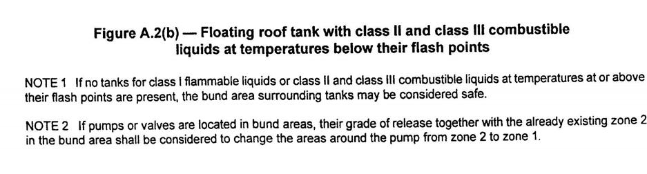
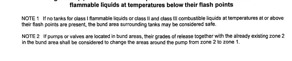
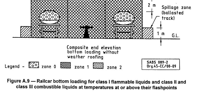
18 ANNEX A (normative) Fuel storage depots The hazardous area classification examples listed below are based on product classes as defined in ZS and using the principles in the IP Code part 15, API RP 500 and ZS IEC Examples are given for: Flammable liquids as defined by this code (see clause 3), which includes class I liquids, as well as class II and class IIIA liquids at or above their flashpoints. Combustible class II and class III liquids as defined by this code, stored or handled below their flash point. Figure Description A.1 Cone or dome roof tank A.2 Floating roof tank A.3 Tank with internal pan A.4 Horizontal tank A.5 Underground tanks A.6 Bottom bulk truck loading A.7 Top and bottom bulk truck loading with canopy A.8 Railcar, top loading A.9 Railcar, bottom loading A.10 Jetties, loading and discharging A.11 Jetties, discharging A.12 Railcar discharge A.13 Drum filling in the open air A.14 Pumps and piping A.15 Separator or interceptor A.16 Workshop 16 All rights reserved

19 17 All rights reserved

20 18 All rights reserved

21 19 All rights reserved
22 20 All rights reserved

23 21 All rights reserved

24 22 All rights reserved
25 Figure A. 6 Bottom bulk truck loading 23 All rights reserved

26 24 All rights reserved
27 Figure A. 8 Railcar, top loading 25 All rights reserved

28 26 All rights reserved
29 Figure A. 11 Jetties, Discharging 27 All rights reserved

30 28 All rights reserved

31 29 All rights reserved
32 30 All rights reserved
33 31 All rights reserved

34 32 All rights reserved
35 33 All rights reserved
ANNEX AMENDMENTS TO THE INTERNATIONAL CODE FOR FIRE SAFETY SYSTEMS (FSS CODE) CHAPTER 15 INERT GAS SYSTEMS
 CHAPTER 15 INERT GAS SYSTEMS") Annex 3, page 2 ANNEX AMENDMENTS TO THE INTERNATIONAL CODE FOR FIRE SAFETY SYSTEMS (FSS CODE) CHAPTER 15 INERT GAS SYSTEMS The text of existing chapter 15 is replaced by the following: "1 Application This
Annex 3, page 2 ANNEX AMENDMENTS TO THE INTERNATIONAL CODE FOR FIRE SAFETY SYSTEMS (FSS CODE) CHAPTER 15 INERT GAS SYSTEMS The text of existing chapter 15 is replaced by the following: "1 Application This
1.8 INDUSTRIAL PROCESS WEIGHING IN HAZARDOUS AREAS
 1.8 INDUSTRIAL PROCESS WEIGHING IN HAZARDOUS AREAS EXPLOSION PROTECTION In addition to the type approval and certification of industrial weighing systems concerned with accuracy, equipment that is also
EXPLOSIVE ATMOSPHERES - CLASSIFICATION OF HAZARDOUS AREAS (ZONING) AND SELECTION OF EQUIPMENT
 AND SELECTION OF EQUIPMENT") EXPLOSIVE ATMOSPHERES - CLASSIFICATION OF HAZARDOUS AREAS (ZONING) AND SELECTION OF EQUIPMENT OVERVIEW ASSESSING THE RISK RELATIONSHIP BETWEEN FIRES AND EXPLOSIONS CLASSIFYING HAZARDOUS AREAS INTO ZONES
EXPLOSIVE ATMOSPHERES - CLASSIFICATION OF HAZARDOUS AREAS (ZONING) AND SELECTION OF EQUIPMENT OVERVIEW ASSESSING THE RISK RELATIONSHIP BETWEEN FIRES AND EXPLOSIONS CLASSIFYING HAZARDOUS AREAS INTO ZONES
NZQA registered unit standard version 3 Page 1 of 7. Plan electrical installations for explosive atmospheres
 Page 1 of 7 Title Plan electrical installations for explosive atmospheres Level 5 Credits 8 Purpose This unit standard is intended for use in the training and assessment of people who work with electrical
C&G 2395 Exam Paper April Section A - All questions carry equal marks. Answer all three questions. Show all calculations.
 C&G 2395 Exam Paper April 2013 Section A - All questions carry equal marks. Answer all three questions. Show all calculations. Q.1 The electrical installation in a small food retail outlet is scheduled
AIDGC PRESENTATION MARCH 2006 HAZARDOUS AREAS STANDARDS & CLASSIFICATION
 AIDGC PRESENTATION MARCH 2006 HAZARDOUS AREAS STANDARDS & CLASSIFICATION Jeff Strath Principal Engineer Paterson Flood Engineers Pty Ltd www.pfe.com.au INTRODUCTION This presentation provides an overview
PART II RULES FOR THE CONSTRUCTION AND CLASSIFICATION OF VESSELS IDENTIFIED BY THEIR MISSIONS TITLE 104 CARRIAGE OF DANGEROUS GOODS
 PART II RULES FOR THE CONSTRUCTION AND CLASSIFICATION OF VESSELS IDENTIFIED BY THEIR MISSIONS TITLE 104 CARRIAGE OF DANGEROUS GOODS SECTION 7 ELECTRICITY CHAPTERS A APPROACH B DOCUMENTS, REGULATIONS AND
Installation of Ballast Water Management Systems
 (Sept 2015) (Rev.1 May 2016) Installation of Ballast Water Management Systems 1. Application In addition to the requirements contained in BWM Convention (2004), the following requirements are applied to
User Information Sheet 015
 User Information Sheet 015 Formerly LPGA Guidance NO.84 March 2007 Inspection and Maintenance of LPG Pipework at Commercial and Industrial Premises 1. Introduction LPG pipework may, under certain conditions,
TABLE OF CONTENT
 Page : 1 of 12 Project Engineering Standard www.klmtechgroup.com KLM Technology #03-12 Block Aronia, Jalan Sri Perkasa 2 Taman Tampoi Utama 81200 Johor Bahru Malaysia TABLE OF CONTENT SCOPE 2 REFERENCES
NZQA registered unit standard version 3 Page 1 of 6
 Page 1 of 6 Title Report on the integrity of explosion-protected electrical apparatus in explosive atmospheres Level 3 Credits 3 Purpose This unit standard covers the explosion-protection aspects of plant
ISO INTERNATIONAL STANDARD. Small craft Liquefied petroleum gas (LPG) systems
 systems") INTERNATIONAL STANDARD ISO 10239 Second edition 2008-02-15 Small craft Liquefied petroleum gas (LPG) systems Petits navires Installations alimentées en gaz de pétrole liquéfiés (GPL) Reference number ISO
INTERNATIONAL STANDARD ISO 10239 Second edition 2008-02-15 Small craft Liquefied petroleum gas (LPG) systems Petits navires Installations alimentées en gaz de pétrole liquéfiés (GPL) Reference number ISO
FLAMMABLE GASES AND FLAMMABLE CRYOGENIC FLUIDS
 CHAPTER 35 FLAMMABLE GASES AND FLAMMABLE CRYOGENIC FLUIDS SECTION 3501 GENERAL 3501.1 Scope. The storage and use of flammable gases shall be in accordance with this chapter. Compressed gases shall also
Intrinsic safety 101 hazardous locations
 Intrinsic safety 101 hazardous locations Protection methods, containment, segregation, and prevention By Robert Schosker This article answers the question, Why worry about hazardous locations? The area
TECHNICAL SPECIFICATION
 TECHNICAL SPECIFICATION IEC TS 61245 Edition 2.0 2015-03 Artificial pollution tests on high-voltage ceramic and glass insulators to be used on d.c. systems INTERNATIONAL ELECTROTECHNICAL COMMISSION ICS
SAFETY MANUAL FOR FLAMMABLE PRODUCT TRANSFER
 SAFETY MANUAL FOR FLAMMABLE PRODUCT TRANSFER SUPPLIMENT TO eom IMPORTANT READ THIS MANUAL BEFORE PRODUCT INSTALLATION, OPERATION, INSPECTION & MAINTENANCE Tougher and more rigid guidelines are being established
Spray Finishing Self-Inspection Checklist
 Optional Information Name of School: Date of Inspection: Vocational Program/Course/Room: Signature of Inspector: Spray Finishing Self-Inspection Checklist Guidelines: This checklist covers some of the
Session #: Selection of Explosion Protected Equipment for Hazardous Locations
 Abstract Session #: (Arial 16) Selection of Explosion Protected Equipment for Hazardous Locations Pieter Coetzee Explosion Prevention Consultant Registered person How can we mitigate the risks of explosions
Drum / cylinder handling
 Page 1 of 8 Drum / cylinder handling This Technical Measures Document covers the storage and handling of toxic and flammable substances in drums and cylinders and refers to relevant codes of practice and
TABLE OF CONTENTS PART 2 - CONFINED SPACES
 May 11, 2006 TABLE OF CONTENTS PART 2 - CONFINED SPACES Page DEFINITIONS... 2-1 GENERAL... 2-2 RESPONSIBILITIES... 2-2 HAZARD ASSESSMENT AND WORK PROCEDURES... 2-3 IDENTIFICATION AND ENTRY PERMITS... 2-3
NZQA registered unit standard version 1 Page 1 of 8. Conduct detailed inspection of electrical installations for explosive atmospheres
 Page 1 of 8 Title Conduct detailed inspection of electrical installations for explosive atmospheres Level 5 Credits 5 Purpose This unit standard is intended for use in the training and assessment of people
Paint Spraying and Other Painting Processes Fire Safety
 April 2011 Country of Origin: United Kingdom Paint Spraying and Other Painting Processes Fire Safety Introduction... 1 Risk Assessment... 2 Recommendations... 2 Location... 2 Heating... 3 Electrical Equipment...
INOGATE Technical Secretariat UK Experience European Standards Implementation Key Expert Phil Winnard Session 2 Georgia, October 2015
 INOGATE Technical Secretariat UK Experience European Standards Implementation Key Expert Phil Winnard Session 2 Georgia, October 2015 BUILDING PARTNERSHIPS FOR ENERGY SECURITY www.inogate.org EN 12186
C&G 2395 Exam Paper June Section A-All questions carry equal marks. Answer all three questions. Show all calculations.
 C&G 2395 Exam Paper June 2013 Section A-All questions carry equal marks. Answer all three questions. Show all calculations. 1. The electrical installation in an industrial unit is scheduled for a periodic
AS/NZS 1596:2014. The storage and handling of LP Gas AS/NZS 1596:2014. Australian/New Zealand Standard. Superseding AS/NZS 1596:2008
 AS/NZS 1596:2014 Incorporating Amendment No. 1 Australian/New Zealand Standard The storage and handling of LP Gas Superseding AS/NZS 1596:2008 AS/NZS 1596:2014 AS/NZS 1596:2014 This joint Australian/New
CABLE ENTRIES IN HAZARDOUS AREAS CORRECT SELECTION, INSTALLATION AND MAINTENANCE
 CABLE ENTRIES IN HAZARDOUS AREAS CORRECT SELECTION, INSTALLATION AND MAINTENANCE Compiled by: Arthur Cameron NOT SO CORRECT SELECTION AND INSTALLATION OF CABLE GLANDS AND JUNCTION BOXES IN HAZARDOUS AREAS
GUIDELINES FOR HAZARDOUS AREA CLASSIFICATION AND ELECTRICAL INSTALLATIONS OF TANKERS
 GUIDANCE NOTES GD 01-2010 CHINA CLASSIFICATION SOCIETY GUIDELINES FOR HAZARDOUS AREA CLASSIFICATION AND ELECTRICAL INSTALLATIONS OF TANKERS 2010 Beijing Contents Chapter 1 General...1 1.1 General...1 1.2
RESOLUTION A.567(14) adopted on 20 November 1985 REGULATION FOR INERT GAS SYSTEMS ON CHEMICAL TANKERS
 adopted on 20 November 1985 REGULATION FOR INERT GAS SYSTEMS ON CHEMICAL TANKERS") INTERNATIONAL MARITIME ORGANIZATION A 14/Res.567 16 January 1986 Original: ENGLISH ASSEMBLY - 14th session Agenda item lo(b) IMO RESOLUTION A.567(14) adopted on 20 November 1985 THE ASSEMBLY, RECALLING
INTERNATIONAL MARITIME ORGANIZATION A 14/Res.567 16 January 1986 Original: ENGLISH ASSEMBLY - 14th session Agenda item lo(b) IMO RESOLUTION A.567(14) adopted on 20 November 1985 THE ASSEMBLY, RECALLING
BRITISH STANDARD BS 341-4: Transportable gas container valves. Part 4: Pressure relief devices ICS
 BRITISH STANDARD BS 341-4:2004 Transportable gas container valves Part 4: Pressure relief devices ICS 23.060.40 This British Standard, having been prepared under the direction of the Standards Policy and
Thermo Probe, Inc. TP-5 TP-7 TP-8. Instruction Manual English. Switch. Display. Carry Strap. Probe. Ground Clip. Switch. Display.
 Display Thermo, Inc. Instruction Manual English TP-5 Display TP-7 Display TP-8 1-1 Thermo, Inc. Instructions for use- Models TP-5, TP-7, and TP-8 The manual describes basic function and use of Thermo instruments
GUIDELINES FOR HAZARDOUS AREA CLASSIFICATION AND ELECTRICAL INSTALLATIONS OF TANKERS
 GUIDANCE NOTES GD 01-2010 CHINA CLASSIFICATION SOCIETY GUIDELINES FOR HAZARDOUS AREA CLASSIFICATION AND ELECTRICAL INSTALLATIONS OF TANKERS 2010 -------------------------------------- China Communications
 Title of Paper Interpretation of IP15 in Process Plant Design: a Commonsense Approach ---------------------------------------------------------------------------------------------------------------------------
DK46 - DK800 Supplementary instructions
 DK46 - DK800 Supplementary instructions Variable area flowmeter Device category II2G with electrical internals Additional Ex manual KROHNE CONTENTS DK46 - DK800 1 Safety instructions 3 1.1 General... 3
FIRE AND EXPLOSION HAZARD MANAGEMENT
 FIRE AND EXPLOSION HAZARD MANAGEMENT Toolbox Talk Practical Applications (Part 2) Setting the standard in oil and gas safety 1 WHAT SHOULD I KNOW ABOUT FIRES AND EXPLOSIONS» One-size-fits-all solution
Hazardous Location Coding System - NEC 500. Type of Protection. XP = Explosionproof. IS = Intrinsically Safe Apparatus
 Hazardous Location Equipment - United States Equipment listed in this category for Hazardous (Classified) Locations is also suitable for installations in areas that are unclassified locations and, unless
Pressure Equipment Directive (PED) 97/23/EC Page 033 of 124
 97/23/EC Page 033 of 124") Pressure Equipment Directive (PED) 97/23/EC Page 033 of 124 13.7 Pressure Equipment Directive (PED) 97/23/EC 1 The Pressure Equipment Directive (PED) 97/23/EC applies to the design, manufacturing and conformity
Pressure Equipment Directive (PED) 97/23/EC Page 033 of 124 13.7 Pressure Equipment Directive (PED) 97/23/EC 1 The Pressure Equipment Directive (PED) 97/23/EC applies to the design, manufacturing and conformity
This document is meant purely as a documentation tool and the institutions do not assume any liability for its contents
 1999L0092 EN 27.06.2007 001.001 1 This document is meant purely as a documentation tool and the institutions do not assume any liability for its contents B DIRECTIVE 1999/92/EC OF THE EUROPEAN PARLIAMENT
OSAT Series. Intrinsically Safe Infrared Temperature Sensor Operator's Guide
 OSAT Series Intrinsically Safe Infrared Temperature Sensor Operator's Guide Issue L Jan 2017 Introduction OSAT Series intrinsically safe non-contact infrared temperature sensors measure the temperature
QUANTIFYING THE TOLERABILITY OF POTENTIAL IGNITION SOURCES FROM UNCERTIFIED MECHANICAL EQUIPMENT INSTALLED IN HAZARDOUS AREAS
 QUANTIFYING THE TOLERABILITY OF POTENTIAL IGNITION SOURCES FROM UNCERTIFIED MECHANICAL EQUIPMENT INSTALLED IN HAZARDOUS AREAS Steve Sherwen Senior Consultant, ABB Engineering Services, Daresbury Park,
Bulletin Swimming pool, hot tub and spa installations Rules , , , , , and
 Bulletin 68-7-11 Swimming pool, hot tub and spa installations Rules 68-000, 68-056, 68-058, 68-064, 68-068, 68-302 and 68-404 Scope (1) Swimming pools - general (2) Grounding & bonding (a) Bonding for
Explosion Protection Technology Pty Ltd
 How to Apply Hazardous Area Australian Standards (Group II) 3-Day On-Site Workshop * 2018 This workshop provides a sound understanding of electrical compliance and your responsibilities in Group II hazardous
Welding With Arc Welding Equipment
 Optional Information Name of School: Date of Inspection: Vocational Program/Course/Room: Signature of Inspector: Welding With Arc Welding Equipment Self Inspection Checklist Guidelines: This checklist
CITY AND COUNTY OF DENVER CR&CF RISK UNIT Compressed Gas Safety Standard
 CITY AND COUNTY OF DENVER CR&CF RISK UNIT 65.5.11 Compressed Gas Safety Standard 1.0 Introduction 2.0 Scope This standard has been developed to protect all City and County of Denver employees and contractors
IECEx Certificate of Conformity Annexe
 for Certificate No.: IECEx TSA 09.004X Issue No.: 1 Equipment description pertaining to Issue 0 of this Certificate: A range of electrical power distribution, control, protection and monitoring equipment
TSS21 Sealed Thermostatic Steam Tracer Trap
 1255050/4 IM-P125-10 ST Issue 4 TSS21 Sealed Thermostatic Steam Tracer Trap Installation and Maintenance Instructions 1. Safety information 2. General product information 3. Installation 4. Commissioning
Dangerous Substances & Explosive Atmospheres Regulation 2002 The Basics. Richard Cowen Dip SH, Dip RSA, CMIOSH, MIIRSM, FRSPH, GI Fire E
 Dangerous Substances & Explosive Atmospheres Regulation 2002 The Basics Richard Cowen Dip SH, Dip RSA, CMIOSH, MIIRSM, FRSPH, GI Fire E DSEAR Regulations 2002 Sets minimum requirements for the protection
IECEx OPERATIONAL DOCUMENT
 IECEx OD 504 Edition 1.0 2009-09 IECEx OPERATIONAL DOCUMENT IEC System for Certification to Standards relating to Equipment for use in Explosive Atmospheres (IECEx System) IECEx Scheme for Certification
NZQA registered unit standard version 2 Page 1 of 7. Conduct a conformity assessment of explosion-protected apparatus
 Page 1 of 7 Title Conduct a conformity assessment of explosion-protected apparatus Level 6 Credits 9 Purpose This unit standard covers the assessment and certification of explosion-protected apparatus
PROCEDURE FOR INITIAL AND PERIODIC INSPECTION POTENTIALLY EXPLOSIVE ATMOSPHERES (HAZARDOUS AREA) ORIGINAL EDITION
 ORIGINAL EDITION") PROCEDURE FOR INITIL ND PERIODIC INSPECTION IN POTENTILLY EXPLOSIVE TMOSPHERES (HZRDOUS RE) ORIGINL EDITION DEC. 1997 This Standard is the property of Iranian Ministry of Petroleum. ll rights are reserved
PROCEDURE FOR INITIL ND PERIODIC INSPECTION IN POTENTILLY EXPLOSIVE TMOSPHERES (HZRDOUS RE) ORIGINL EDITION DEC. 1997 This Standard is the property of Iranian Ministry of Petroleum. ll rights are reserved
The evolution of the Ex-proof flame path
 April 2017 The evolution of the Ex-proof flame path As written in previous dissertation, the most critical part of a flameproof enclosure 'Ex d' is the flame path. Although the Standards are divided into
INTERNATIONAL STANDARD
 INTERNATIONAL STANDARD ISO 10464 First edition 2004-08-15 Gas cylinders Refillable welded steel cylinders for liquefied petroleum gas (LPG) Periodic inspection and testing Bouteilles à gaz Bouteilles rechargeables
MST21 Stainless Steel Balanced Pressure Thermostatic Steam Trap
 1250650/6 IM-P125-07 ST Issue 6 MST21 Stainless Steel Balanced Pressure Thermostatic Steam Trap Installation and Maintenance Instructions 1. Safety information 2. General product information 3. Installation
DSEAR-Classification of Hazardous Areas (Zoning) and Selection of Equipment
 and Selection of Equipment") OHSS: Classification of Hazardous areas (Zoning) and selection of equipment Guidance 202 DSEAR-Classification of Hazardous Areas (Zoning) and Selection of Equipment Contents Overview... 2 Assessing the
OHSS: Classification of Hazardous areas (Zoning) and selection of equipment Guidance 202 DSEAR-Classification of Hazardous Areas (Zoning) and Selection of Equipment Contents Overview... 2 Assessing the
Intertek Testing Services Taiwan Ltd.
 1) The testing results relate only to the items tested. Page 2 of 21 2) The test report shall not be reproduced except in full, without written approval of the laboratory. 3) This test report only allows
Hazardous (Classified) Locations
 Locations") Hazardous (Classified) Locations Presented by: John Chambers UL HazLoc operations Presented at: Safety & You in 2002 2002 Safety Conference Flexible Packaging Association (FPA) 1 AREA CLASSIFICATIONS Class
Hazardous (Classified) Locations Presented by: John Chambers UL HazLoc operations Presented at: Safety & You in 2002 2002 Safety Conference Flexible Packaging Association (FPA) 1 AREA CLASSIFICATIONS Class
Pressure Systems Safety Regulation
 Pressure Systems Safety Regulation Introduction This document informs Faculty of the key requirements of the UK and Chinese Pressure Systems Safety regulations. The aim of these regulations is to prevent
Health and Safety at Work (Hazardous Substances Reduced Secondary Containment for Certain Above Ground Stationary Tanks) Safe Work Instrument 2017
 Safe Work Instrument 2017") Health and Safety at Work (Hazardous Substances Reduced Secondary Containment for Certain Above Ground Stationary Tanks) Safe Work Instrument 2017 This safe work instrument is approved under section 227
Health and Safety at Work (Hazardous Substances Reduced Secondary Containment for Certain Above Ground Stationary Tanks) Safe Work Instrument 2017 This safe work instrument is approved under section 227
CONTRACTOR WHS HAZARD STANDARD HAZARDOUS CHEMICALS EXTERNAL USE ONLY
 CONTRACTOR WHS HAZARD STANDARD HAZARDOUS CHEMICALS EXTERNAL USE ONLY Principles in the Optus Contractor WHS management process CONTRACTOR MANAGEMENT STAGES PRINCIPLES THIS STANDARD REQUISITION Requisition
Liquefied Petroleum Gas Market Regulations S.L
 Liquefied Petroleum Gas Market Regulations S.L. 423.31 INSPECTION & RISK ASSESSMENT REPORT ON LPG SECONDARY STORAGE INSTALLATIONS i Fill-In Instructions: (i) This LPG Secondary Storage Inspection report
ENGINEERING STANDARD FOR HAZARDOUS AREA ORIGINAL EDITION DEC. 1994
 ENGINEERING STANDARD FOR HAZARDOUS AREA ORIGINAL EDITION DEC. 1994 This Standard is the property of Iranian Ministry of Petroleum. All rights are reserved to the owner. Neither whole nor any part of this
DSEAR- Storage, Use and handling of gas cylinders guidance.
 OHSS: Storage, Use and handling of gas cylinders guidance 202 DSEAR- Storage, Use and handling of gas cylinders guidance. Contents Introduction... 2 General recommendations for storage, use and handling....
Protocol for Confined Space Entry Requirements
 Occupational Health and Safety (OHS) Policy Document Number # QH-PTL-275-12-1:2012 Protocol for Confined Space Entry Custodian/Review O fficer: Director Safety and Wellbeing Version no: 1.0 Applicable
Rules for Classification and Construction Ship Technology
 I Rules for Classification and Construction Ship Technology 1 Seagoing Ships 9 Oil Recovery Vessels Edition 1993 The following Rules come into force on 1st September, 1993. The respective latest edition
ES18 Security Theory/Regulations Answer Schedule
 ES18 Security Theory/Regulations Answer Schedule Notes:1. means that the preceding statement/answer earns 1 mark. 2. This schedule sets out the expected answers to the examination questions. The marker
Cal/OSHA T8 CCR 1536 Cal/OSHA T8 CCR 4799 Cal/OSHA T8 CCR 4845 Cal/OSHA T8 CCR 4848
 Cal/OSHA Gas Systems for Welding GAS WELDING Cal/OSHA T8 CCR 1536 Cal/OSHA T8 CCR 4799 Cal/OSHA T8 CCR 4845 Cal/OSHA T8 CCR 4848 When performing gas welding, the following precautions, work procedures,
Pressure Switches Application Guideline
 Pressure Switches Application Guideline Product Overview The Fema Pressure Switch product portfolio provides devices suitable for many applications. The portfolio contains Special functions and equipment
Low Voltage Electricity System Safety Rules & Associated Safety Guidance
 Annex J To Loughborough University Facilities Management (FM) Health and Safety Policy Low Voltage Electricity System Safety Rules & Associated Safety Guidance 1. Introduction a. These Safety Rules are
FV Flash Vessel Installation and Maintenance Instructions
 4041050/5 IM-P404-10 EMM Issue 5 FV Flash Vessel Installation and Maintenance Instructions 1. Safety information 2. Specific product safety information 3. Product information 4. Installation 5. Commissioning
Rockhampton Office Brisbane Office Tarong Site. Barron Gorge Hydro PS Kareeya Hydro PS Mica Creek PS
 Business Procedure Hot Work Document Number OHS-PROC-128 This document applies to the following sites: All Sites Rockhampton Office Brisbane Office Tarong Site Barron Gorge Hydro PS Kareeya Hydro PS Mica
GUIDELINES FOR SURVEY OF OIL FLOATING STORAGE VESSELS FIXED AT ANCHORAGE
 GUIDANCE NOTES GD03-2017 CHINA CLASSIFICATION SOCIETY GUIDELINES FOR SURVEY OF OIL FLOATING STORAGE VESSELS FIXED AT ANCHORAGE 2017 Effective from 1 March 2017 BEIJING Chapter 1 GENERAL 1.1 Application
SOP. Working in Confined Spaces
 Purpose This procedure outlines the requirements for the management of entry into confined spaces in all work areas with the intention of minimising risks to health and safety from any potential hazards
ENGINEERING STANDARD FOR HAZARDOUS AREA SECOND EDITION JANUARY 2016
 IPS-E-EL-110(2) ENGINEERING STANDARD FOR HAZARDOUS AREA SECOND EDITION JANUARY 2016 This Standard is the property of Iranian Ministry of Petroleum. All rights are reserved to the owner. Neither whole nor
Spirax Compact FREME Flash Recovery Energy Management Equipment
 IM-UK-cFREME UK Issue 1 Spirax Compact FREME Flash Recovery Energy Management Equipment Installation and Maintenance Instructions 1. Safety information 2. General product information 3. Installation 4.
API MPMS Chapter 17.6 Guidelines for Determining the Fullness of Pipelines between Vessels and Shore Tanks
 API MPMS Chapter 17.6 Guidelines for Determining the Fullness of Pipelines between Vessels and Shore Tanks 1. Scope This document describes procedures for determining or confirming the fill condition of
API RECOMMENDED PRACTICE 500 THIRD EDITION, DECEMBER 2012 ERRATA, JANUARY 2014
 Recommended Practice for Classification of Locations for Electrical Installations at Petroleum Facilities Classified as Class I, Division 1 and Division 2 API RECOMMENDED PRACTICE 500 THIRD EDITION, DECEMBER
Pioneers. Ex-ENGINEERING. Quality
 Pioneers The increasing demands of industry for dependable explosionproof lighting, motivated Baliga to pioneer the design and manufacture of a quality line way back in 1962, when the first Indian Standards
PSSI 36 General Confined Spaces, Tunnels, Culverts and Similar Spaces
 1. SCOPE This document now includes provision for safe access to cable tunnels and culverts previously covered in PSSI 37 which is now withdrawn. The term Confined Space is defined in the Confined Spaces
Hot Work Program. University of Wisconsin-Platteville Reviewed 4/2016
 Hot Work Program University of Wisconsin-Platteville Reviewed 4/2016 The purpose of the Hot Work Program is to establish safety procedures for employees, contractors, and subcontractors engaging in any
Transport of gas tanks for motor vehicles
 United Nations Secretariat ST/SG/AC.10/C.3/2016/51 Distr.: General 30 August 2016 Original: English Committee of Experts on the Transport of Dangerous Goods and on the Globally Harmonized System of Classification
Compiled by: B Beard. Approved by: SH Carstens. Description of requirements and procedures for compact provers to be used as verification standards.
 1. Scope Description of requirements and procedures for compact provers to be used as verification standards. 2. Reference documents Trade Metrology Act SANS1698 3. Policy A. BASIC REQUIREMENTS Compact
Vision Painting Inc Safety Management System
 Abrasive Blasting 1. PURPOSE The purpose of this program is to provide training and qualification guidelines for the safe operation of Abrasive Blasting. The Safety Officer is responsible for facilitating
CP10 Sensor Installation and Maintenance Instructions
 4030150/9 IM-P403-26 EMM Issue 9 CP10 Sensor Installation and Maintenance Instructions 1. Safety information 2. General product information 3. Installation 4. Maintenance 5. Spare parts Copyright 2017
WELDING, CUTTING AND BRAZING
 - 1 - WELDING, CUTTING AND BRAZING Are only authorized and trained personnel permitted to use welding, cutting or brazing equipment? Does each operator have a copy of the appropriate operating instructions
Contractors' Code of Safe Practice
 Contractors' Code of Safe Practice Introduction As the controller of premises, The University of Hong Kong has a duty to ensure, so far as is reasonably practicable, the health and safety of all its employees,
PROPERTY & ESTATES GROUP
 PROPERTY & ESTATES GROUP SAFE WORKING PROCEDURE 2-17-04 WORKING IN CONFINED SPACES Purpose of Document This document describes SRUC s policy and procedure for working in confined spaces. It applies to
Overview EUSSAM12. Carry out tightness testing and direct purging of gas installations
 Overview This standard covers tightness testing and direct purging of low or medium pressure gas, in accordance with approved procedures and practices. It covers the standards required to meet the requirements
Savard Labor & Marine Staffing, Inc. Compressed Gas Safety Program Rev3/14
 Compressed Gas Safety Program Purpose: The purpose of this safety policy and procedure is to establish guidelines for the protection and safety of this company s employees who handle and use compressed
BCGA GUIDANCE NOTE 17
 BCGA GUIDANCE NOTE 17 BCGA POLICY AND GUIDANCE FOR THE SAFE FILLING OF THIRD-PARTY OWNED AND / OR MAINTAINED TANKS Revision 2: 2013 BCGA GUIDANCE NOTE 17 BCGA POLICY AND GUIDANCE FOR THE SAFE FILLING OF
Further technical information is available on
 1 of 5 Manufacture address : Bartec Technor AS Dusavikveien 39 4007 Stavanger Norway Further technical information is available on www.bartec-technor.no Note on instructions When working in hazardous areas,
Safety Services Guidance. Guidance on: The Provision and Use of Work Equipment Regulations 1998 (PUWER)
") Guidance on: The Provision and Use of Work Equipment Regulations 1998 (PUWER) Key word(s) : Work equipment. Using, maintaining and repairing. Information, instruction and supervision. Risk Assessment.
Guidance on: The Provision and Use of Work Equipment Regulations 1998 (PUWER) Key word(s) : Work equipment. Using, maintaining and repairing. Information, instruction and supervision. Risk Assessment.
Class 2 Gases Learning Tool
 Class 2 Gases Learning Tool This work has been produced by DGL (Aust) Pty Ltd This Learner s Guide is about the skills and knowledge required to store and warehouse Class 2 Gases at DGL (Aust) facilities.
BT6HC Hygienic Sanitary Balanced Pressure Steam Trap for High Capacity and CIP/SIP Applications
 1800350/6 IM-P180-12 ST Issue 6 BT6HC Hygienic Sanitary Balanced Pressure Steam Trap for High Capacity and CIP/SIP Applications Installation and Maintenance Instructions 1. Safety information 2. General
Manual Actuated Boiler Blowdown Valves
 Manual Actuated Boiler Blowdown Valves Installation and Maintenance Instructions 1. Safety information 2. General product information 3. Installation 4. Operation 5. Maintenance 6. Spare parts p.1 1. Safety
Check with local zoning official for property line distance requirements.
 RESIDENTIAL POOL PLAN SUBMITTAL GUIDELINES The following guidelines are intended to assist municipal residents with the permit acquisition process with regard to pools, spas and hot tubs for single family
Vacuum Excavation in the vicinity of the Wellington Electricity Network
 Vacuum Excavation in the vicinity of the Network. Document no: ENG-116 Document Rev: 1 Issue Status: Final Issue Date: 14/05/2015 Page 1 of 9 Contents 1. PURPOSE... 3 2. POLICY... 3 3. SCOPE... 3 4. REFERENCES...
F All types of inert gas systems are to comply with the following:
 (1974) (Rev.1 1983) (Rev.2 1987) (Rev.3 May 1998) (Corr. Sept 2001) (Rev.4 May 2004) (Rev.5 Nov 2005) (Rev.6 May 2012) (Rev.7 May 2015) Inert Gas Systems.1 General Requirements.1.1 All types of inert gas
Hazardous Location Coding System - For Division. Class I / II / III, Division 1 / 2 Type of Protection. XP = Explosionproof
 Hazardous Location Equipment - Canada Equipment listed in this category for Hazardous Locations is also suitable for installations in areas that are non-hazardous locations and, unless referenced in the
New Hampshire Public Utilities Commission CFR 49 Part 192 Regulations. MINIMUM Pipeline Safety Regulations
 New Hampshire Public Utilities Commission CFR 49 Part 192 Regulations MINIMUM Pipeline Safety Regulations Application for Jurisdictional LPG Operators 1 Pipeline Safety Regulations 49 CFR Part 192 (NOTE:
Magnetic level switch type MR783 Instruction Manual
 Magnetic level switch Magnetic level switch type MR783 1. DESCRIPTION page 3 1.1 Operation page 3 1.2 Application page 3 1.3 Description page 3 2. SPECIFICATIONS page 3 2.1 Service Conditions page 4 2.2
Australian Standard. The storage and handling of gases in cylinders AS (Incorporating Amendment No.1) AS
 AS") AS 4332 2004 (Incorporating Amendment No.1) AS 4332 2004 Australian Standard The storage and handling of gases in cylinders This Australian Standard was prepared by Committee CH-009, Safe Handling of Chemicals.
AS 4332 2004 (Incorporating Amendment No.1) AS 4332 2004 Australian Standard The storage and handling of gases in cylinders This Australian Standard was prepared by Committee CH-009, Safe Handling of Chemicals.