Dew Point Mirror 573. Operation and Maintenance Manual V3.1
|
|
|
- Randolf Franklin
- 5 years ago
- Views:
Transcription

1 Dew Point Mirror 573 Operation and Maintenance Manual V3.1
2
3 Warranty MBW Calibration Ltd. (MBW) guarantees that its products are manufactured to the highest quality of material and workmanship specifications. MBW guarantees the reliability of its products for a period of 24 months from the date of initial shipment when operated in normal use and within the specified design limitations. Under this Warranty, MBW will, at its discretion, repair or replace any component that upon examination by MBW or its duly authorized representatives proves to be defective during the warranty period provided the system is returned to the factory for inspection and repair shipping prepaid. Improper or unauthorized maintenance, storage, repair, or alteration of any kind by personnel other than MBW or its duly authorized representatives may void all warranties. Warranty may also be voided for misuse, neglect, accident, corrosion, and improper installation. This Warranty is exclusive and in lieu of any and all other warranties of merchantability, fitness for a particular purpose, or any other warranty, expressed or implied, and all other liabilities and obligations on the part of MBW. MBW will not be liable for any other claims or damages, either direct, indirect, or consequential arising out of the use of its products. Original manuals are prepared in English and German. Translations in other languages are available, but in the event of any discrepancy, the German or English versions will be considered as the official version. Subject to change without notice. For the latest version of this manual please visit our website. Copyright MBW Calibration AG Seminarstrasse 55/57 CH-5430 Wettingen / Switzerland phone fax sales@mbw.ch 573_MANUAL_E_V3.1 i
4 ii 573_MANUAL_E_V3.1
5 Table of Contents WARRANTY... 1 TABLE OF CONTENTS SAFETY INSTRUCTIONS... 1 KEY FEATURES... 3 QUICK START Unpacking Mirror Cleaning Starting the Humidity Measurement Sample Gas Connections... 8 GET TO KNOW THE Front Panel Data Lines Status Line Fixed Function Keys Menu Keys and Navigation Touch Screen Measuring Head Mirror Assembly Optical Module Back Panel inch Rack SYSTEM CONFIGURATION The Menu Overview Selection of Indicated Parameters Selection of Numeric or Graphic Data Display Graph Scaling Control Setup _MANUAL_E_V3.1 iii
6 5.4.1 Dew/Frost Control Water Cooling ORIS (573S only) Mirror Cleaning (573S only) Mirror Check Heating Control (573H / HX only) Pump Settings Control Setup Steam Trap Configuration Selection of Units Selection of Color Configuration of Optional Analog Outputs Diagnostic Functions System Information Ice Test Peltier Cooling Test RS-232 Configuration SET UP AND OPERATION Measurement Set Up Determination of the measurement range Sample Tubes Steam Trap Pressure Sample Gas Flow Sample Gas Contamination External Temperature Set Fixed External Temperature Application Integration High Temperature Applications Fuel Cells Meteorology Dry Gases Dew Point Calibration Climatic Chamber Validation Contaminated Applications Operational Considerations Mirror Check Interval iv 573_MANUAL_E_V3.1
7 6.4.2 Inlet Filters Sample Gas Flow Temperature Measurement INSTALLATION Facility Requirements Environmental Power Instrument Cooling Heating of the Sampling System Preparation for Use Benchtop Use Rack Mounting Sample Tube Connection Preparation for Shipping or Transportation REMOTE COMMUNICATION Hardware Connection and Cabling Communication Settings Command Syntax General Use Termination Characters Leading and Trailing Spaces Case Sensitivity Numerical Values Command Reference Measurement Data System Identification Stability Indicators Global Control Parameters Advanced Features MAINTENANCE Calibrate the Touch Screen Mirror Cleaning Removing the Measuring Head Cover Inspecting and Cleaning the Mirror Reassemble the Mirror Components Exterior Cleaning _MANUAL_E_V3.1 v
8 9.4 Calibration Peltier Cooling Test Periodic Maintenance Checks ERROR MESSAGES Heater Feedback Sensor Failure SPECIFICATIONS DRAWINGS FAQ S vi 573_MANUAL_E_V3.1


9 1 Safety Instructions IMPORTANT, please read the Safety Instructions carefully: Check all connections carefully before use Disconnect power supply before opening the instrument housing In the event of damage do not use the instrument Depending on the operation, the following parts of the instrument may get very hot: Measuring head Gas Inlet/Outlet External heated tube connection 573_MANUAL_E_V3.1 1
10 2 573_MANUAL_E_V3.1
11 2 Key Features Precise and Stable Humidity Measurement The 573 Dew Point Mirror is a high performance 19 rack format instrument with an integral measuring head, pressure sensor, sample pump and flow meter for continuous precision measurement of frost/dew point, temperature, pressure and calculated humidity parameters in a wide range of applications. The humidity measurement of the 573 is based on the chilled mirror condensation technology which provides highly precise, stable and repeatable results. ForceFrost Function At temperatures below 0 C water can condense either as frost or dew (supercooled water), this makes it difficult to determine whether the condensate layer on the mirror is liquid or solid. The Force Frost function over-cools the mirror to force the condensed layer to the solid phase. This eliminates the uncertainty of whether dew or frost point is measured. By rapid cooling of the mirror to a temperature below -40 C the formation of an ice layer is assured and the system then stabilizes the mirror at the frost point temperature. More information about Force Frost and how it s configured are detailed in section Dew/Frost Control on page 30. Mechanical Flow Meter The 573 includes an integrated mechanical flow meter that provides the user with indication and control of the sample gas flow. Configurable Sampling Circuit The 573 sampling circuit can be configured by the user to suit different application scenarios. The measuring head, flow meter and sample pump use separate internal tubing that is connected using the 573 back panel links. The user can therefore bypass the flow meter and sample pump when needed, for example when measuring at high dew points. LCD Display with Touch Panel The 573 has a full color LCD touch panel with a high contrast ratio and a wide viewing angle for easy readability. Data is displayed in large, easy-to-read fonts. Using the on-screen buttons and menus, you can easily configure each line of the display for a variety of humidity, temperature, and pressure parameters that may be viewed in either SI or non-si units. 573_MANUAL_E_V3.1 3
12 Ice Test Function Users can perform a check of the 573 system stability at any time using the built-in Ice Test function that provides instant verification of system accuracy and integrity. See chapter Ice Test page 44. Measuring Head and Sample Tube Heating - 573H and HX only When measuring high dew points, condensation will occur if any section of the sample path is at a temperature below the dew point temperature. This will result in measurement errors and flooding of the sample path. To avoid this and to achieve precise measurements, the 573H and HX include heating of the sample path, measuring head and external inlet sample tube. For further information, please see section 6 Set Up and Operation, page 49. ORIS - 573S only ORIS (Optimal Response Injection System) accelerates the measurement when low frost points are measured, typically when the gas is drier than about -40 C frost point. ORIS works by a temporary injection of a small amount of water vapor in to the sample gas flow. This speeds up the formation of a frost layer on the mirror surface and reduces hours of delay into just minutes. ORIS is typically used for measurements below -40 C. The threshold for its operation can be set by the user. For further information please see page _MANUAL_E_V3.1
13 3 Quick Start This section guides you through the set-up and most important first steps when using the 573. It is a summary and should only be used as a general overview. Do not use it as a substitute for the remainder of the manual. To understand the instrument thoroughly, please read the other sections carefully. 3.1 Unpacking The 573 will be delivered to you in a cardboard transportation box, or if ordered, a custom transport case. It is recommended to keep the delivery packaging in case of future need for transport for calibration or storage. The following items are typically included: 573 Dew Point Mirror Temperature probe PT(100) with cable Power cable Gas connections 6mm or ¼ Swagelok Operation manual Calibration certificate Optional heated inlet sample hose (H/HX only) Optional steam trap (H/HX only) Before you start operating the 573, carefully remove all items from the case and visually check for any signs of damage. Check the packing list contents are all included, and if you are missing any item or find something is damaged, please contact your supplier immediately. Make sure that the power rating on the back label corresponds to your power supply specification. 3.2 Mirror Cleaning The heart of the 573 is a highly sensitive and precise chilled mirror measuring head. To achieve high accuracy, it should be cleaned prior to each measurement. Maintaining the mirror in a clean condition is fundamental to best measurement capability. The exact procedure is described in section 9.2 Mirror Cleaning on page _MANUAL_E_V3.1 5
14 3.3 Starting the 573 The 573 needs a source of AC power. It will work over a wide power range and will most likely operate at your local voltage and frequency. Check the back panel label for the power requirements for your specific instrument. 1. Plug the supplied AC power cord into the back of the instrument, then into an AC outlet. 2. The power switch is located next to the AC power connector. Turn the power switch to ON. The display should become visible within a few seconds. If nothing happens, check the power source. After approximately 30 seconds the 573 is ready for measurement. Measurement does not start until Dew/Frost Control is activated by pressing the front panel 6 573_MANUAL_E_V3.1

 readings are required, an external temperature probe must be connected. Alternatively, a fixed external temperature value may be entered via the touch screen.")
15 3.4 Humidity Measurement When you switch on the 573 the default display will show the pressure in the measuring circuit. If a temperature probe is connected, an external temperature reading will also be displayed. Dew/frost point will also display current mirror temperature, but not the actual dew/frost point. To measure humidity (dew point, frost point, RH, etc.), Dew/Frost Control must be started and gas should be flowing through the measuring head. If relative humidity (RH) readings are required, an external temperature probe must be connected. Alternatively, a fixed external temperature value may be entered via the touch screen. Please follow the instructions in section Set Fixed External Temperature page 52. To test the 573 humidity measurement by measuring the dew point temperature of the room, follow these simple steps: Check that the back panel sample connections are in place as shown. This is the standard set up of the 573 back panel connections. Depending on your application these connections may be configured differently than shown on the picture. As the 573 s measuring head is internal, to obtain a representative sample of the room air, flow through the measuring head is required. Press the Pump button to generate gas flow. Pump power can be varied, see section Pump on page 38. Using the mechanical flow meter, adjust the flow rate to the ideal condition of 0.5 lpm. 573_MANUAL_E_V3.1 7


16 Start the measurement by pressing the Dew/Frost Control key. This button enables the system to cool the mirror to the dew or frost point temperature, monitor the thickness of the condensation layer on the mirror, and precisely adjust the mirror temperature to maintain a stable condensation layer. When Dew/Frost Control is enabled, the indicator on the key will turn green and the dew or frost point temperature display will begin to show the mirror temperature as it cools to the condensation point. See section 6 Set Up and Operation page 49 for further information. Please be aware that you may not receive a Stable indication when measuring ambient humidity. Humidity fluctuations in an open space are much greater than in a generator or climatic chamber. A fluctuation of ± 0.2 C is normal for room conditions. See section 5.2 Selection of Indicated Parameters page 25 for information on how to select the parameters you want to display. 3.5 Sample Gas Connections The 573 is equipped with fittings for gas inlet and outlet connection. This allows the 573 to measure the humidity of generators, chambers and other equipment that can be connected using sample tubes. 573S 573H and HX The inlet and outlet connections are located on the back panel of the instrument and are clearly labeled as shown in the picture on the left. Connections are either 6mm or ¼ inch Swagelok (specified at the time of ordering) _MANUAL_E_V3.1
17 The back panel layout is different depending on the instrument version. For more detailed information on sample gas connections, see section 4.4 Back Panel page 17 Measuring range limits Each version of the 573 has a specific dew point measurement range, please refer to section 6.1 Measurement Set Up page 49 for guidance. For measurement of dew points above ambient temperature, measuring head and sample tube heating must be used. Otherwise condensation will occur and this may damage the instrument. If you have a 573H or HX, an electrical connection point for the control of an external heated sample tube, Hose Heater, is fitted. For more information on this topic see section 'Heating Control (573H / HX only) page _MANUAL_E_V3.1 9
18 10 573_MANUAL_E_V3.1


19 4 Get to know the Front Panel The front panel of the 573 is equipped with a full color touch screen and a keypad for data entry. To activate a menu option or toggle a function on or off, simply touch the desired key or object directly on the screen. When the 573 is turned on, the display will activate within a few seconds. A sample display configuration is shown below. The display configuration can be customized, so your display may be different. The use and the functions of the display are described in the following sections. 573S and 573H Data Lines Status Line Fixed Function Keys Menu Keys Keypad Flow Meter Measuring Head 573HX Heated Measuring Head 573_MANUAL_E_V3.1 11


20 4.1.1 Data Lines The first three lines of the display show a numeric or graphic representation of the measured data. We will refer to these first three lines as Data Lines. If numeric, a data line contains the value to the left, with the parameter description and units to the right. If graphic, a data line shows a simple graph of data over time. Data can be displayed in different parameters and units either numerically or graphically. Please refer to section 5 System Configuration on page 23 to learn how to configure your preferences Status Line Near the bottom of the display is the Status Line. The Status Line displays Balance, Density, Contamination, and Flow or Optic Power. The last field can be toggled between Flow and Optic Condition indicator. You can switch the displayed data by pressing directly on the indicator. Balance Although it is directly obtained from the intensity of the mirror s reflected light signal, balance is effectively the first derivative of the dew thickness measurement. It indicates the rate of growth or reduction of the condensation layer on the mirror. While the dew or frost layer on the mirror surface is growing, the indicator will be above center. The faster the layer is growing, the higher the indication. Conversely, when the layer on the mirror surface is reducing (evaporating), the indicator will be below center. The faster it disappears, the lower the indication. When the indicator is in the center, the thickness of the dew or frost layer is neither growing nor reducing, and the condensate layer on the mirror surface is in equilibrium with the gas. In this center position of the indicator, there is no net exchange of water vapor between the gas and the mirror surface. If the humidity of the gas sample is homogeneous and of low enough variability for the control system to sense a steady value, the Balance indicator will show a green Stable message, accompanied by a few short beeps _MANUAL_E_V3.1

21 Density The density indicator graphically depicts the approximate thickness of the dew or frost layer on the mirror surface. The 573 can automatically differentiate between dew and frost layers and the indicator will display the current condensation state. The label in the density indicator will change from Layer Density (when the state of the layer is uncertain) to either Dew Density or Frost Density (when either dew or frost is being measured). For more information regarding dew/frost point determination see section Dew/Frost Control on page 30. Mirror Residue The mirror residue indicator shows the amount of mirror contamination that was detected during the last mirror check (see section Mirror Check on page 35). If the bar covers more than a quarter of the space, we recommend that you clean the mirror. Flow The flow indicator shows the current gas flow over the mirror in liters per minute or the unit of flow selected by the user. Optic Condition The optic condition indicates the aging of the LED. When the instrument is used at higher measuring head temperatures, the LED will age more quickly. When new, the optic condition bar graph will show as full. When the indication starts to decrease, it provides the user with advanced notification that the LED of the optical module may need service or replacement Fixed Function Keys 573S 573H/HX The bottom line of the display contains a row of fixed function keys. These keys are used to start and stop the Pump, prepare for Mirror Cleaning (573S only), toggle the Heater on/off (573H and HX only), initiate a Mirror Check, and switch Dew/Frost Control on/off. 573_MANUAL_E_V3.1 13
22 4.1.4 Menu Keys and Navigation Use the dark grey key on the bottom (menu selection key) to move between menus. On the right hand side of the display there is a column of menu keys. The bottom, dark grey key changes the current menu by cycling to the next menu. Each of the light grey keys change their label and function based on the menu that is currently selected. The menu selection is circular. Once you go past the last menu, the first one will appear again and the selection repeats. You can use the ± key on the keypad to move backward through the menus. Use the Enter key to exit the menu. 4.2 Touch Screen The 573 dew point mirror is operated using the touch screen. To make a menu selection or switch functions on or off, touch the screen where appropriate with your finger or a conductive stylus. Never use sharp objects, damage may occur. Before using the 573 for the first time or when several users operate this unit, the touch screen can be calibrated to suit the user. The procedure is described in section 9.1 Calibrate the Touch Screen on page _MANUAL_E_V3.1

23 4.3 Measuring Head The heart of the chilled mirror 573 is the measuring head. It is designed to be highly sensitive, accurate, robust and easily accessible for regular cleaning. Although cleaning the mirror is not necessary before the first use, you might want to familiarize yourself with the location and accessibility of the mirror and the other optical components. WARNING: Depending on the operating mode the measuring head parts can get very hot. Check the head temperature before handling and allow cooling if necessary. The schematic below is a cross section of the complete measuring head including the optical module where the light source and detector are mounted. The mirror PRT is identified in this case with the temperature C, and in normal circumstances this temperature can be anywhere within the operating range of the instrument. Mirror Mirror Assembly The mirror assembly consists of a 6 mm diameter rhodium plated mirror, the mirror temperature sensor (PRT) and a Peltier thermoelectric element. These parts are carefully assembled during production and rarely require repair or replacement. The mirror PRT is carefully characterized before being fitted and its stability is fundamental to the stability of the whole instrument. If the mirror or PRT are damaged by the user and need to be replaced, the calibration history of the instrument is lost. 573_MANUAL_E_V3.1 15

24 4.3.2 Optical Module The Optical Module contains an LED light source and a photodiode light detector (opto-electronic components). This assembly is used to detect the formation and thickness of condensation on the mirror surface. In the event of damage or failure, the optical module can easily be repaired or replaced. This will have no effect on the calibration of the instrument. 573S and 573H 573HX Removing the Optical Module The measuring head of the dew point 573 is located on the right side of the front panel. To access the mirror or the optical module, the measuring head cover or measuring head clamp need to be removed. The method depends on the model of 573. To access the mirror and the optical module of the 573S and H, the measuring head cover is removed by unscrewing counter clockwise approximately three turns. The optical module is the black part located under the measuring head cover. The 573HX head is different from the 573S and H. It features parts that enable heating to higher temperatures. In this case the optical module is also the measuring head cover. To remove, loosen the metal clamp by unscrewing counter clockwise. Once the head cover or clamp mechanism is removed, the optical module can easily be removed by pulling gently from the guide pin or clamp mounts. The optical module contains an O-ring that seals the measuring head and gold electrical contacts. Do not touch the inner surface of the optical module with your fingers to avoid contamination of the contacts, the O-ring, the optical components and the gas path. For more instructions on disassembly of the measuring head and mirror cleaning, see section 9.2 Mirror Cleaning on page _MANUAL_E_V3.1


25 4.4 Back Panel 573S 573H/HX Power Switch The main power switch is on the back panel above the power plug. The power supply has a built-in fuse and will automatically switch off in case of overload. To restart power, the main power switch must be switched off and on again. Power Plug The supplied power cord is connected to the power socket on the instrument back panel. The supported power supply voltage is VAC / VAC at 50 to 60Hz. The power requirements are specified on the serial number label on the back of the instrument. RS-232 The RS-232 port can be used to connect the 573 to a computer. The necessary 9-pin RS-232 (serial) extender cable (1:1 pinout) is a common accessory and can easily be obtained at any computer store. 573_MANUAL_E_V3.1 17


26 Optional Analog Outputs The 573 can be ordered with two optional analog outputs which are independently configurable. For each of the analog outputs, you can choose which parameter to transmit and scale its range. Please refer to section Configuration of Optional Analog Outputs on page 42 to learn how. If the instrument is ordered with the optional analog outputs, two 4-pin LEMO connectors (Part Number: FGG.1B.304.CLAD52 will be supplied with the instrument. These can be used to make up a custom cable for your installation. When the 4-pin LEMO connector is properly assembled, the red dot of the connector housing should be between pin 1 and 4. The red dot is between pin 1 and 4 Pin Signal Position Description 1 2 +V -V When viewing the solder points of a disassembled 4-pin LEMO connector, pin 1 is usually identified with a full or partial circle drawn around it. Pin 4 3 +I should have no identifier. When wiring the cable, note that the pin numbering of the socket in the back panel of the 4 -I instrument starts at the top left (pin 1) and goes counter-clockwise (as viewed from the rear of the unit). The 573 allows both a voltage and a current output signal. As shown in the illustration above, pins 1 and 2 connect the voltage signal (V), and pins 3 and 4 the current signal (I). Inside the instrument, the output signal is connected from a DAC and then split into a voltage and a current signal. Therefore you may use either a volt or current meter to measure the analog signal. The maximum voltage output range is V. The following table identifies the corresponding current signal. Configuration of the analog outputs is described in section 5.8 Configuration of Optional Analog Outputs on page 42. Voltage [V] Current [ma] N/A _MANUAL_E_V3.1
27 Measuring Head Input/Output Inlet sample gas is connected directly to the measuring head. Inside the 573, there is the shortest possible stainless steel connecting tube to the measuring head. On 573H and HX units, the internal gas inlet and outlet tubes are heated. The outlet from the measuring head returns to the back panel where the sample gas can be directly vented or connected to the flow meter and/or sample gas pump. To prevent condensation when measuring at dew points above ambient temperature, excess water vapor must be condensed or trapped if the gas flow is connected to the flow meter or sample pump inlet connections. Inlet Sample Hose Heating For measurement of dew points above ambient temperature, an external heated sample hose must be used to prevent condensation in the sampling system. The 573H and HX are both equipped with a connection and internal control for one external heated hose. The electrical connector Hose Heater is next to the gas input fittings. For control of the external heated hose, see section Heating Control (573H / HX only) on page 37. Flow Meter Input/Output The flow meter sample connection allows sample gas to pass through the 573 s front panel mounted flow meter and needle valve. This allows the sample gas flow rate to be measured and set by the user. A flow of 0.5 l/min is optimal. For low frost points a higher flow up to 1l/min is optimal. The flow meter and its internal connecting tubes are not heated, so when measuring at higher than ambient temperature dew points, the flow meter can be bypassed to avoid internal condensation or flooding. By fitting a steam trap on the outlet from the measuring head, the internal flow meter can also be used when measuring dew points above ambient temperature. For more information see section Steam Trap on page 50. Gas Pump Input/Output The 573 is fitted as standard with an internal sample pump that can be used to flow sample gas through the measuring head where the application is at ambient pressure (for example sampling room or chamber conditions). The pump rate can be changed using the touch panel and the flow rate adjusted using the 573 flow meter (see Section 6.1.5). The internal gas pump connecting tubes and the sample pump itself are not heated, so when measuring at higher than ambient dew points, the gas pump can be bypassed to avoid internal condensation or flooding. By fitting a steam trap on the outlet from the measuring head, the internal sample pump can be used, see section Steam Trap on page _MANUAL_E_V3.1 19
 are calculated by the 573.")
28 External Temperature Probe The external temperature socket on the back panel is used for the connection of an external temperature probe. External temperature measurements are required if certain humidity parameters, such as relative humidity (%rh) are calculated by the 573. External temperature measurements are not required for dew or frost point measurements. If you wish to connect your own Pt100 probe, the 573 requires a 5 pin LEMO connector ( part number FGG.1B.305.CLAD52. Red dot aligns with pin 1 After identifying pin 1, follow the line counter-clockwise from pin 1 to all other pins in succession. Wire the cable according to the following scheme: Pin Signal Position Description 1 Shield 2 +I 3 +V 4 -I 5 -V When viewing the solder tubs of a disassembled 5-pin LEMO connector, pin 1 is usually identified with a full or partial circle drawn around it. Pin 5 should have no identifier. When wiring the cable, note that the pin numbering of the socket in the back panel of the instrument starts at the top left (pin 1) and goes counter-clockwise (as viewed from the rear of the unit). When the 5-pin LEMO connector is properly assembled, the red dot of the connector housing is located directly above pin 1. If a user s own PRT is used, the external temperature PRT coefficients in the 573 will need to be changed and this will invalidate any calibration of the temperature measurement performed during production. Contact MBW or your supplier for further advice _MANUAL_E_V3.1
29 Cooling Water Connection The 573 is equipped with an additional water cooling connection. This allows a flow of water to cool the measuring head to increase the mirror depression capability beyond the normal working limits of the Peltier thermoelectric cooler that regulates the mirror temperature. Water cooling can also be useful in applications where the ambient temperature is high and low frost/dew points are measured. The temperature of the water circulated should always be regulated to a temperature ABOVE the ambient dew point temperature to avoid condensation formation. Steam Trap (573H / HX only) This connection allows the automated control of a steam trap on the gas outlet from the measuring head. This means that water vapor with a dew point above the temperature of the steam trap will condense into the trap. If a project specific connecting cable is required for a steam trap, a LEMO connector, part number FGG.1B.302.CLAD52 ( can be used. Red dot is placed on pin 1 After identification of Pin 1, further pins are arranged according to the order in the counterclockwise direction. The pin assignment is as follows: Pin Signal Position Description 1 +24V (max. 15W) 2 GND When looking at the solder points of a disassembled 2-pin LEMO connector, pin 1 is usually identifiable by a full or partial circle around. Pin 2 should have no identification inch Rack The 573 housing is a standard 4U 19 rack format. This means that the instrument can be installed within rack systems or enclosures and secured by means of the four front panel mounting holes. See page 81 for drawings showing the dimensions. 573_MANUAL_E_V3.1 21
30 22 573_MANUAL_E_V3.1
31 5 System Configuration Many aspects of the 573 can be configured depending on your measuring needs and preferences. You can choose which humidity, temperature, and pressure values will be indicated on the screen, their order and units, and whether each will be shown as a number or as a graph. In addition to the display options, you can define how the 573 performs its control functions, such as Dew/Frost determination. Any changes in the configuration settings will remain active until the next time they are changed. Color settings will be restored to the standard settings after restarting the instrument. 5.1 The Menu Overview The 573 has several menus to configure the system to meet your requirements. Use the dark gray menu selection key to cycle through each of the menus. Each time you press the menu selection key, the respective label will indicate which menu is currently active. Use the ± key on the keypad to move backward through the menus. Use the Enter key on the numerical keypad to exit the menus. This is not necessary, however, as staying in a specific menu will not affect the measurement. List of available menus: (9) 0 - Default Screen, Menu off No menu is selected. All the keys are blank. 1 - Parameter This menu is used to select the parameters displayed on the data lines. 2 - Numeric/Graphic This menu is used to toggle a data line between numerical and graphic display. 3 - Control Setup 1 This menu is used to configure the control functions like dew/frost control, mirror check, pump power, heating configuration etc. 4 - Control Setup 2 This menu is used to configure further control functions like the steam trap and ORIS 5 - Units 1 This menu is used to select the units in which you would like the data to be displayed. Unit changes will be applied to all values displayed on the screen This menu configures the units for temperature, pressure and flow rate. 573_MANUAL_E_V3.1 23
32 6 - Units 2 This menu is used to select the units in which you would like the data to be displayed. Unit changes will be applied to all values displayed on the screen. This menu configures the units for absolute humidity, specific humidity and vapor pressure parameter. 7 - Foreground Color The menu Fore Color is used to temporarily change the color of the lines drawn on graphs and the color of text (numbers and letters). The foreground color of each data line can be changed individually. Unlike other settings, the color settings will be restored to the standard color settings when the 573 is restarted. 8 - Background Color The menu Back Color is used to temporarily change the color of the background of the numeric or graphic data lines. The background color of each data line can be changed individually. Unlike the other settings, the color settings will be restored to the standard color settings when the 573 is restarted. 9 - Analog Outputs If the analog output option is fitted to the 573, it can be configured in this menu Diagnostic Functions Here you have access to the System Info, Ice Test, Peltier Cooling Test (PCT) and baud rate settings for the RS232 port _MANUAL_E_V3.1
33 5.2 Selection of Indicated Parameters In the Parameter menu you can choose which parameters you would like to have displayed on the data lines. When you select parameters for display on any of the four data lines, those selections remain valid until you change them again, even after you turn the 573 off. Below you will find the list of the available parameters. The numbers included are used in the configuration the optional analog outputs, also see page 42. Parameter Dew Point Frost Point %RH %RH WMO Volume Ratio Weight Ratio Absolute Humidity Specific Humidity Vapor Pressure Head Pressure Flow Rate External Temp Head Temp Status Line Mirror Temp Explanation The temperature to which a gas must be cooled to start condensing water vapor to liquid water. Dew point is pressure dependent and must be stated together with its associated pressure. The temperature to which a gas must be cooled to start deposition of water vapor in the form of ice. Frost point is pressure dependent and must be stated together with its associated pressure. Frost point exists only below 0 C. While not technically correct, it has been common industry practice to report values below 0 C as dew point, although frost point is the correct term. For further explanation on dew or frost point refer to section Dew/Frost Control. The ratio between the amount of water vapor in a sample and the maximum amount possible at that same temperature and pressure. The ratio between the amount of water vapor in a sample and the maximum amount possible at that same temperature and pressure calculated using the World Meteorological Organization (WMO) formula. The ratio between the water vapor volume and the total volume of the sample gas, generally expressed in parts per million by volume, ppm v or its numerical equivalent μl/l. Once determined, ppm v has no further pressure dependence. It is also independent of the gas type or mixture. Weight ratio is the ratio between the mass of water vapor and the total mass of the sample gas, generally expressed in parts per million by weight, ppm w or its numerical equivalent mg/kg. Once determined, ppm w has no further pressure dependence, but depends on the gas type and mixture through the molecular weight of the constituents. The weight of water vapor per unit volume of humidified gas. A ratio of the water vapor to the total weight of the humidified gas. The partial pressure exerted by vapor in thermodynamic equilibrium with its condensed phases (solid or liquid) at a given temperature. It is usually expressed in kpa. The pressure of the gas sample in the measuring head. The flow rate of gas. The temperature measured by the external temperature probe. The temperature measured by the PRT in the measuring head. This Data Line Displays Data like Balance Indicator, Dew density This parameter shows the mirror temperature. 573_MANUAL_E_V3.1 25
34 Follow the steps below to choose the parameters you wish to have displayed on the four data lines: 1. Select the Parameter menu by pressing the dark gray menu selection key until Parameter appears. Small left pointing arrows will appear on the four upper menu keys. 2. Press the arrow key next to the data line you wish to change. Each time you press the arrow key, the parameter of the respective line will change. Continue pressing the arrow key until the parameter you wish to view is displayed. 3. Change the parameters on any of the other data lines the same way. 4. If you choose the parameter External Temp, but have not connected the external temperature sensor, no reading will be displayed. Please make sure all the relevant equipment is connected for the instrument to be able to display the chosen parameters _MANUAL_E_V3.1

35 5.3 Selection of Numeric or Graphic Data Display Any data line may be viewed either in a numeric or a graphic format. The 573 automatically keeps a short data history of every selectable parameter so that a graph appears instantly whenever a data line is switched from numerical to a graphic mode. Use the Numeric/Graphic key to toggle any data line between numerical or graphic mode. 1. Use the dark gray menu selection key to select the Numeric/Graphic menu. Small left-pointing arrows will appear on the four upper menu keys next to the data lines. 2. Press the arrow key next to the data line that you wish to change. The data line will toggle between numerical and graphic mode each time you press the key Graph Scaling Each graph can have its own x and y-axis scaling and range settings. There are three different scaling modes to choose from; Autoscale Minimum (which is the default setting), Fixed Range or Minimum/Maximum. Each of these is explained in more detail below. You can change the graph scaling and switch between the three scaling modes at any time. 1. On the screen, touch the graph you wish to change. A graph scaling dialog box will appear. One of the buttons in the Description column will have a green indicator. This shows you the currently selected mode. 2. If you would like to change the scaling mode, touch the button of the mode you would like to select. Note that for the Minimum/Maximum option, only the Maximum button needs to be selected (the Minimum is then automatically selected by the system). 3. Touch the corresponding field in the Change To column, next to the range that you have selected. 4. Using the numerical keypad, enter the value needed. If you make a mistake while entering the value, touch the field you are editing on the screen. With each touch, the last digit in the field will be erased. 5. Once you have entered the correct value, press the Ok button (or the enter key on the numeric keypad) to confirm. Press the Cancel button if you wish to abort all changes made in the dialog box. Any values you enter will only be accepted by the system if they correspond with the selected mode. If, for example, you enter a value into the bracket next to the Autoscale Minimum, but Fixed Range is the selected mode, the Autoscale Minimum value will remain unchanged. 573_MANUAL_E_V3.1 27
36 Autoscale Minimum The Autoscale Minimum mode is the default setting for this instrument. This mode sets the scaling automatically so that all of the stored data will be visible on the graph at the best possible resolution. As the range of the data changes, so will the range of the graph. In Autoscale Minimum mode, you can select the minimum range that you want the graph to scale to. For viewing temperature and dew or frost point graphs, setting the Autoscale Minimum to a value of 0.1 or greater is generally a good choice. It allows the graph range to close in on the data as it stabilizes at a single value without the range of the y-axis becoming too narrow. For example, setting an Autoscale Minimum of 0.1 while the 573 is displaying a graph of a steady dew point measurement of 20.0 C will set the minimum and maximum value limits of the graph to C and C, respectively. The graph will also zoom out as needed if a reading goes outside that range. You can experiment with this value to determine your personal preference. Fixed Range The Fixed Range mode allows you to select a fixed range for the graph s y-axis. It automatically centers on the most recent data point. As the most recent data varies, so will the center point of the graph, leaving the overall range fixed. The Fixed Range mode is mostly used to monitor data for stability. For example, if you set the fixed range for the external temperature graph to 0.2 and the current data is C all data between C and C is visible on the graph. Minimum/Maximum In the Minimum/Maximum mode you can specify the minimum and maximum values used for the graph s y-axis. Unlike the other modes, the visible range of the graph s y-axis will not automatically change if a data point is outside the set minimum/maximum range. If the data points are outside the specified range, you will not see them on the graph. Time Span Time Span determines the number of minutes of the data history that is visible on the graph. The 573 stores a fixed number of data points independent of the selected time span. Thus, changing the time span will change the time interval at which the data points are stored. The total number of stored data points will not change. With a time span of 15 (15 minutes), the graph data is sampled and stored every few seconds. With a time span of 120 (2 hours), the graph data is only sampled, stored, and updated about once a minute. When you change the time span, the data that was sampled and stored at the old interval will be incrementally replaced by new data sampled at the new interval. The time span indicated on the graph will always reflect the actual time span of the data that is displayed on the graph, and will agree with the time span you selected once enough data points have been sampled. The selected time span is common to all graphs, so they will always have the same time relationship to one another _MANUAL_E_V3.1
37 The time span can be changed in the Numeric/Graphic menu: 1. Touch the graph you wish to change on the screen. The Graph Scaling dialog box will appear. 2. Touch the Change To: field next to Time Span. The field will turn white. 3. Use the numerical keypad to enter an even value between 2 and As you enter the value it will appear in the white Change To: field of the dialog box. 4. If you make an entry error, touch the field that holds the number you wish to change. Each time you touch the field, the last digit entered will be deleted. 5. Press the OK button in the dialog box or press Enter on the key board to confirm the new value. Press Cancel to leave it unchanged. 6. The result will take some time to show as the old data at the old time interval will be replaced by data at the new time interval gradually as determined by your selected time span. If you prefer to see the same measurement as both numerical value and graph, you may select the same parameter on two data lines, and set one line to graph mode and the other to numeric mode. See pages 25 and 27 for instructions on selecting displayed parameters and changing their display modes. 573_MANUAL_E_V3.1 29
38 5.4 Control Setup 1 The Control Setup 1 menus enable you to control the manner in which the 573 operates Dew/Frost Control To measure humidity (dew point, frost point, RH, etc.), Dew/Frost Control must be started and gas should be flowing through the measuring head. Force Frost Below When measuring dew/frost points between 0 C and -20 C, condensation on the instrument s chilled mirror may be in the form of dew, frost, or a combination of both. If the state of the condensation is not known, it will introduce errors into all the humidity measurements reported by the instrument. To eliminate this potential source of error, the Force Frost function is used to rapidly cool the mirror to below -20 C, forcing all dew on the mirror into frost. The mirror will then re-stabilize at the frost point temperature. Once the condensate layer is in a state of frost, it will remain frost for all sub-zero mirror temperatures, allowing the instrument to measure the frost point accurately. The dew point and all other humidity measurements are then mathematically calculated from the frost point. To change the Force Frost settings: 1. Select the Control Setup 1 menu by pressing the dark gray menu selection key until Control Setup 1 appears. 2. Touch the Dew/Frost Control button. The Mirror Dew/Frost Control window will open. 3. The Force Frost function can be enabled or disabled by touching the Force Frost Below button. If the indicator on the left side of the button is green, Force Frost is enabled. If the indicator is grey, Force Frost is disabled. 4. To adjust the temperature below which Force Frost activates, touch the Change To: field to the right of the Force Frost Below button. The field will turn white. 5. Enter the temperature in degrees C below which Force Frost should activate. 6. If you make an entry error, touch the field that holds the number you wish to change. Each time you touch the field, the last digit entered will be deleted. Press the OK button in the dialog box or press Enter on the keyboard to confirm the new value. Press Cancel to leave it unchanged _MANUAL_E_V3.1


39 Why it is Important to distinguish between Dew and Frost For mirror temperatures above 0 C, water vapor always condenses on the mirror in its liquid phase (dew). A condensation layer on a mirror above 0 C is therefore always considered a dew point. Although ice always melts at exactly 0 C, water will not necessarily freeze at 0 C. Water may stay in its liquid phase at temperatures far below 0 C. This phenomenon is referred to as Super-Cooled Water. The fact that water at subzero temperatures can condense either as dew or as frost makes it somewhat difficult to determine whether the condensate layer on the mirror at temperatures below 0 C is liquid or solid. Various factors such as contaminants, time, pressure etc. may cause the condensate layer to remain liquid at mirror temperatures of 20 C and below. It is important to understand that the difference in the temperature at which the liquid or the solid condensate layer stabilizes can be up to 3 C. As shown on the picture to the right, it is also possible that dew and frost exist concurrently on the mirror which results in a non-stable value reading somewhere between the dew and frost point. Therefore the phase of the condensate must be known in order to avoid significant errors and to correctly calculate all humidity values, including vapor pressure, dew point, %RH, volume ratio, weight ratio, absolute humidity and specific humidity. It would be desirable for manufacturers and users of humidity instruments to use the term frost point for temperatures below zero and dew point for temperatures above zero. While not technically correct, it has been common practice to use dew point for temperatures below 0 C, although frost point would be the correct term. As discussed above, dew point can exist below 0 C in the form of super-cooled water and is different in value from the equivalent frost point temperature. For the same vapor pressure, the frost point is approximately 10% of reading above the corresponding dew point value (when expressed in C). For example, a vapor pressure of 38 Pa corresponds to a frost point of 30 C and a dew point of 33 C. From a measuring perspective it seems obvious that a clear and consistent distinction between dew and frost point is important. 573_MANUAL_E_V3.1 31
40 5.4.2 Water Cooling All 573 instruments are equipped with a water cooling function. This allows the connection and control of water flow through the measuring head so that mirror cooling capability can be increased, and lower dew/frost points can be measured. To change the Water Cooling settings: 1. Select the Control Setup 1 menu by pressing the dark gray menu selection key until Control Setup 1 appears. 2. Touch the Dew/Frost Control button. The Mirror Dew/Frost Control window will open. 3. The Water Cooling function can be enabled or disabled by touching the Water Cooling Below button. If the indicator on the left side of the button is green, Water Cooling is enabled. If the indicator is grey, Water Cooling is disabled. 4. To adjust the mirror temperature below which the Water Cooling valve should open, touch the gray Change To: field to the right of the Water Cooling Below button. The field will turn white. 5. Enter the temperature in degrees C below which the Water Cooling should activate. 6. If you make an entry error, touch the field that holds the number you wish to change. Each time you touch the field, the last digit entered will be deleted. Press the Ok button in the dialog box or press Enter on the keyboard to confirm the new value. Press Cancel to leave it unchanged. Take care that the temperature of the cooling water is not below the ambient dew point temperature or condensation may occur on the connecting tubes _MANUAL_E_V3.1
 speeds up the measurement of low humidity, typically when the gas is drier than about -40 C frost point.")
41 5.4.3 ORIS (573S only) At low frost point conditions, the time to stabilize a condensate layer can be significant, sometimes as long as two hours for correct equilibrium. The ORIS (Optimal Response Injection System) speeds up the measurement of low humidity, typically when the gas is drier than about -40 C frost point. ORIS reduces the stabilization time using a carefully programmed vapor injection procedure that accelerates the formation of a frost layer and then interfaces with the mirror control system to maintain stability. This speeds the formation of a frost layer on the mirror surface, so that measurement takes a minutes rather than hours. If the threshold temperature entered by the user is reached as the mirror cools down and no condensate is detected, the ORIS valve will open and carefully inject vapor until a layer starts to form. The 573S will then close the ORIS valve and automatically control the layer thickness until stable. To change the ORIS settings: 1. Select the Control Setup 1 menu by pressing the dark gray menu selection key until Control Setup 1 appears. 2. Touch the Dew/Frost Control button. The Mirror Dew/Frost Control window will open. 3. The ORIS function can be enabled or disabled by touching the Enable ORIS Below button. If the indicator on the left side of the button is green, ORIS is enabled. If the indicator is grey, ORIS is disabled. 4. To adjust frost point temperature below which the ORIS should be activated, touch the gray Change To: field to the right of the Enable ORIS Below button. The field will turn white. 5. Enter the frost point temperature in degrees C below which the ORIS should activate. 6. If you make an entry error, touch the field that holds the number you wish to change. Each time you touch the field, the last digit entered will be deleted. Press the Ok button in the dialog box or press Enter on the keyboard to confirm the new value. Press Cancel to leave it unchanged. 573_MANUAL_E_V3.1 33

42 The following graph shows how ORIS helps decrease the time needed for the system to stabilze when measuring low humidity: _MANUAL_E_V3.1


43 5.4.4 Mirror Cleaning (573S only) Activating the Mirror Cleaning function with the respective key at the bottom of the screen will heat the mirror to a pre-specified temperature, preparing the measuring head ready for the removal of the cover and the optical module. If the mirror and other internal measuring head components are disassembled while they are cold and become exposed to normal atmospheric air, the possibility of undesired condensation exists. Warming the mirror and other internal components to a safe head removal temperature, greater than or equal to the current ambient temperature, will prevent the formation of dew on the mirror assembly during servicing. To set the Minimum Mirror Temperature when activating the Mirror Cleaning mode: 1. Select the Control Setup 1 menu by pressing the dark gray menu selection key until Control Setup 1 appears. 2. Touch the Mirror Cleaning menu button. 3. Touch the Change To: field to the right of the Minimum Mirror Temp label. 4. Enter the temperature in degrees C which the mirror must warm to during the Mirror Cleaning mode. It is recommended that you enter your current ambient temperature or higher. 5. If you make an entry error, touch the field that holds the number you wish to change. Each time you touch the field, the last digit entered will be deleted. Press the Ok button in the dialog box or press Enter on the keyboard to confirm the new value. Press Cancel to leave it unchanged Mirror Check Mirror Check is the process of warming the mirror to evaporate all condensation, looking for the presence of contamination and accounting for it if necessary, then initiating a new dew or frost point measurement. Mirror Check may be started manually with the fixed Mirror Check key, or if enabled, it will start automatically at pre-specified time intervals. During a mirror check, whether triggered automatically or manually, the indicator on the fixed Mirror Check key has the following meanings: Red: The mirror is heating. Brown: The mirror is holding at the programmed Mirror Check Temperature. Yellow: The mirror is cooling to re-form the dew or frost layer. Gray: The mirror check function is not currently active. 573_MANUAL_E_V3.1 35


44 Once the system has re-established a dew or frost layer and become stable, the mirror check function is completed and the color indicator turns gray. After the Mirror Check is completed the bar of the Mirror Residue Indicator shows the amount of contamination remaining on the mirror. If the bar covers more than a quarter of the space, we recommend that you clean the mirror. For instructions on mirror cleaning, please refer to section 9.2 Mirror Cleaning on page 70. Automatic Mirror Check To view or edit the Mirror Check parameters, press the Mirror Check key of the Control Setup 1 menu. If automatic mirror checks are desired, select it by pressing the Cycle Time button. The green indicator on the left side of the button shows that automatic mirror check is enabled. When the automatic mirror check is enabled, the Mirror Check key at the bottom of the screen shows a countdown timer indicating the time before the next automatic mirror check is performed. In the automatic mode, the mirror check may still be initiated manually by pressing the Mirror Check button. Cycle Time The Cycle Time is the number of minutes between automatic mirror check operations. Use the numerical keypad to enter the desired cycle time in minutes. Heating Time The Heating Time determines how long the mirror check temperature will be held before allowing the next dew or frost point measurement. A heating time of 0 means that the instrument will resume dew or frost point measurement immediately after reaching the mirror check temperature. If a heating time greater than 0 is entered, the mirror will heat and remain at that temperature for the chosen duration. Heating time is effective regardless of whether mirror check is triggered automatically or manually. Temperature Edit the Temperature field to change the temperature, in degrees C, that the mirror will be heated to, and optionally held at during Mirror Check. If you have entered a wrong value into a field and want to erase it, press the entry field to backspace _MANUAL_E_V3.1


 heating is completely independent from the heating of the external heated hose, any combination of control is acceptable.")
45 5.4.6 Heating Control (573H / HX only) For the purpose of measuring high dew points, the 573H and HX are equipped with heating of the measuring head and the internal measuring head inlet/outlet sample tubes. There is also provision for the connection and control of one external heated sample hose to connect between the 573H or HX and the device under test. The measuring head and all internal heated sample tubes are controlled at a common set point. A separate control set point is available for the external heated sample hose. Both variables may be defined as either fixed set points, or a delta temperature above the current mirror temperature, and may be enabled/disabled independently. It is also possible to run one heater group in a fixed set point mode, with the other running in delta mode. Since the measuring head (and internal components) heating is completely independent from the heating of the external heated hose, any combination of control is acceptable. But keep in mind that all components, including external fittings and interconnects must also remain above the dew point of the gas being measured to prevent condensation with the tubing. To change the Heater Control settings: 1. Select the Control Setup 1 menu by pressing the dark gray menu selection key until Control Setup 1 appears. 2. Touch the Heater Config button. The Internal Heater Control window will open. 3. The different heating modes can be enabled or disabled by touching the respective button. If the indicator on the left side of a button is green it is enabled, if the indicator is grey it is disabled. 4. To adjust the temperature of the measuring head, internal tubing and external heated hose, touch the gray Change To: field to the right of the respective button. The field will turn white. 5. Enter the heat to temperature in degrees C. 6. If you make an entry error, touch the field that holds the number you wish to change. Each time you touch the field, the last digit entered will be deleted. Press the Ok button in the dialog box or press Enter on the keyboard to confirm the new value. Press Cancel to leave it unchanged. Press the Heater Config button in the Control Setup 1 menu. The green indicators on the left side of the buttons show whether the heater control is enabled, and whether it operates with a fixed set point or at a certain delta above the mirror temperature. Once configured enabled at the desired fixed or delta set points, turn the heaters ON or OFF using the fixed Heater button. 573_MANUAL_E_V3.1 37
46 While it may not be evident from front panel indications, all systems automatically control the head temperature to maintain it at or above 20 C regardless of the status of the heater controls. This is done to prevent the head from cooling to a value that might allow condensation to form on the external head components such as the screw cover or optical head. All systems are equipped with controls for the head heater. This is done to allow those systems to automatically maintain the head temperature at or above 20 C as mentioned in the previous note. If you enter a head heater set point, enable the control and turn on the heater, you may heat the head to values higher than 20 C. The main purpose for this ability is to allow you to drive excess water from the measuring head if you suspect condensation to have formed. WARNING: When using the heater functions above 50 C, surfaces of the measuring head (included the mounting bolts on the HX) and the gas inlet and outlet connectors on the 573H and HX can be very hot and can cause burns if touched. Take care and wear protective gloves if handling hot components Pump Settings All 573 versions include a sample pump that allows the instrument to extract a sample from the application for measurement. The pump has variable power so that the user can change the flow rate using the pump as well as the flow control valve. Before setting pump power, fully open the front panel valve. Setting the pump duty to its lowest setting extends its operation life, but with low settings, the pulsing of the diaphragm within the pump will create small pulses of the gas pressure that will be shown by the flow meter indicator. It is recommended that the pump power is set within the range % Warning: the internal sample pump is not heated, so any gas flow must be at a dew point below the ambient temperature. To adjust the pump settings: 1. Select the Control Setup 1 menu by pressing the dark gray menu selection key until Control Setup 1 appears. 2. Touch the Pump menu button. 3. Touch the Change To: field to the right of Pump Power [%]. 4. Enter the percentage value at which you would like the pump to operate. 5. If you make an entry error, touch the field that holds the number you wish to change. Each time you touch the field, the last digit entered will be deleted. Press the Ok button in the dialog box or press Enter on the keyboard to confirm the new value. Press Cancel to leave it unchanged _MANUAL_E_V3.1

47 5.5 Control Setup Steam Trap Configuration This function configures the control of a valve to drain the MBW steam trap or a user s own cold trap system. To change the Steam Trap settings: 1. Select the Control Setup 2 menu by pressing the dark gray menu selection key until Control Setup 2 appears. 2. Touch the Steam Trap button. The Steam Trap Config window will open. 3. If an automatic steam trap drain cycle is desired, select it by touching the Cycle Time button. The green indicator on the left side of the button shows that the automatic steam trap drain cycle is activated. If the steam trap cycle is activated, you will see on the Steam Trap menu button a countdown of the time until the next drain activation. 4. To adjust the cycle time of the automatic drain function, touch the gray Change To: field to the right of the Cycle Time button. The field will turn white. 5. Enter the required time in minutes. The cycle time defines the time in minutes until the next opening of the drain valve. 6. The Drain Time is the amount of time that the valve opens in seconds. If you would like increase or decrease the opening time of the valve click on the gray Change To: field to the right of Drain Time. The field will turn white. 7. If you make an entry error, touch the field that holds the number you wish to change. Each time you touch the field, the last digit entered will be deleted. Press the Ok button in the dialog box or press Enter on the keypad to confirm the new value. Press Cancel to leave it unchanged. On each system reboot, the steam trap will be deactivated. See section Steam Trap on page 50 for more information. 573_MANUAL_E_V3.1 39
48 5.6 Selection of Units You can display system data in any of a wide variety of units. When you change units, your selection will remain until you change it again. Unit selections are global, which means that all values of that parameter type across the whole system will change to the chosen units. For example, changing the temperature units to C will display all temperature data in C. Data retrieved via RS-232 will always be in SI units regardless of the units chosen for display. Also note that settings within dialog boxes used for changing system parameters are entered and displayed in SI units. Units only affect the four data lines. Available units are: Temperature Units Pressure Units Flow Rate Units C, F or K Pa, hpa, MPa, atm, bar, mb, inhg, mmhg, cmhg, inh 2 O, mmh 2 O, cmh 2 O, Torr or psia l/min, ml/min, l/h, cfm, or cfh Absolute Humidity Units g/l, g/m 3, or lb/ft 3 Specific Humidity Units Vapor Pressure Units g/g, g/kg, or lb/lb Pa, hpa, kpa, MPa, atm, bar, mb, inhg, mmhg, cmhg, inh 2 O, mmh 2 O, cmh 2 O, Torr, or psia _MANUAL_E_V3.1

49 5.7 Selection of Color The foreground and/or background color of any data line can be changed in the Fore Color and Back Color menus. Access the Fore Color and Back Color menus with the menu selection key. To revert to the default color scheme, press and hold key number 9 on the keypad for a few seconds until the instrument beeps. Foreground Color The foreground color is the color of the numbers and letters. To change a data line s foreground color: 1. Access the Fore Color menu. Fore Color will appear on the dark gray menu key, and the keys above will show left-pointing arrows. Note that each of the upper keys correspond to the data lines they point to. 2. Press the arrow key of the data line you wish to change. Note that the foreground color of the data line will change with each touch of the key. 3. Change the foreground color on any of the other data lines the same way. Background Color To change a data line s back color: 1. Access the Back Color menu. Back Color will appear on the dark gray menu key, and the keys above will show left-pointing arrows. Note that each of the upper keys correspond to the data lines they point to. 2. Press the arrow key of the data line you wish to change. Note that the background color of the data line will change with each touch of the key. 3. Change the background color on any of the other data lines in the same way. 573_MANUAL_E_V3.1 41

50 5.8 Configuration of Optional Analog Outputs For each of the analog outputs, you may select which parameter to track and how to scale the selected parameter to the analog output range. These selections are made for each of the analog outputs via the Analog Outputs menu. 1. Access the Analog Outputs menu with the menu selection key. 2. To make the selections for the first analog output, press the Analog Output 1 key. 3. Use the numerical keypad to enter the desired values. For details on each option, read the three following subsections. 4. Follow the same procedure for the second or any subsequent analog outputs as needed. Selection of Parameter to Track In the analog configuration window, enter the number which corresponds to the parameter you wish to track. Use the following table to identify which number to enter into the Parameter field. For example if you wish to track the external temperature, enter number 11 into the entry field next to Parameter. Parameter Units Enter this # Dew Point [ C] 0 Frost Point [ C] 1 RH [%] 2 RH WMO [%] 3 Volume Ratio [PPMv] 4 Weight Ratio [PPMw] 5 Absolute Humidity [g/m 3 ] 6 Specific Humidity [g/kg] 7 Vapor Pressure [Pa] 8 Head Pressure [Pa abs] 9 Flow Rate [l/min] 10 External Temperature [ C] 11 Head Temperature [ C] _MANUAL_E_V3.1
51 Scaling the Output Signal Use Min Value and Max Value to set the range of the Parameter, and use Min Voltage and Max Voltage to set the range of the analog output signal. Example 1 1. You want to track the parameter %RH as an analog voltage output. The previous table on page 42 shows that the parameter %RH has been allocated number 2. Enter number 2 into the field next to Parameter. 2. The next step is to define the range of %RH which will be covered with the analog output signal. You want to have the whole range of 0 100%. Enter 0 into the field next to Min Value and 100 into the field next to Max Value. 3. Then, set the scaling of the analog output signal. You want to have 0 1 VDC on the analog output to represent the %RH. Enter 0 into the field next to the Min Voltage and 1 into the field next to Max Voltage. Example 2 To keep things simple, we will take the same Parameter, Min Value and Max Value settings as in the first example. However, this time you want the analog output range to be scaled to ma instead of volts. Your selected range is 4 20 ma for the parameter range of %RH. In order to enter this into the system, please refer to the table on page 18 to find the voltage which corresponds to your desired ma output range. You will find that 2 10 V corresponds to 4 20 ma. Thus, enter 2 into the field next to Min Voltage and 10 into the field next to Max Voltage. Calibration Adjustment DAC Cal Gain and DAC Cal Zero are used to adjust the analog output signal accuracy. This adjustment is made at the factory and will rarely need to be changed by the user. 573_MANUAL_E_V3.1 43


52 5.9 Diagnostic Functions System Information When you press the System Info button in the Diagnostic Functions Menu a window appears which gives you information about the model of the instrument, the version of the software and the serial number of the instrument Ice Test Measurement accuracy can be checked with a simple built-in test. This Ice Test may be performed at any time, and is recommended whenever the results of your normal measurements do not correspond to expectations, and you suspect that there may be an error with the instrument. Ice Test cannot be started as long as a dew/frost point measurement is in progress. Make sure that the bar on the Dew/Frost Control key is grey. Press the menu selection key on the lower right to select the Diagnostics Functions menu. Then press the Ice Test button _MANUAL_E_V3.1


53 Press the Ice Test menu key. A window requests you to open the measuring head. Disassemble the measuring head as explained in section 9.2 Mirror Cleaning on page 70. Confirm that you opened the measuring head and are ready for the Ice Test by pressing the Ok button. The test starts immediately after pressing the Ok button. During Ice Test, the mirror rapidly cools to approximately - 30 C. Because the measuring head is open, humidity from the ambient air starts to condense on the mirror. This forms a frost layer on the mirror which can be increased if necessary by breathing on it. After reaching the low temperature and forming ice on its surface, the mirror begins to heat. As the temperature approaches 0 C, the instrument will beep increasingly rapidly as the mirror gets closer to the ice-melt temperature. Watch the mirror closely. As soon as the mirror temperature reaches 0 C, the ice will melt into liquid water drops (phase transition). When you see the phase transition on the mirror, press the Ok button. The mirror temperature is measured at that moment and a dialog box appears with the test results. If the measured ice-melt temperature was in the range of ± 0.2 C, the check is successful and will be indicated with the calibration status PASS. 573_MANUAL_E_V3.1 45
54 If the measured ice-melt temperature was outside the range of ± 0.2 C, the check was not successful and indicated with the calibration status FAIL. In this case, clean the mirror and repeat the ice test. If it continues to fail, the instrument should be sent to the manufacturer or an authorized agent for evaluation and/or repair. Press the Ok button on the PASS/FAIL status window. The next window requests that you clean the mirror. Clean and reassemble the measuring head as described in section 9.2 Mirror Cleaning on page Peltier Cooling Test The Peltier module used for mirror cooling and heating can age over time. It can also lose capability when used at its limits. If you think the measuring head is not cooling down fast enough during measurement, you can check this with the Peltier Cooling Test (PCT) function. This function will perform a stress test of the peltier module. It cools the peltier module down for two minutes with the highest allowed current (5 Amps). During this test, the measuring head will heat up a little as power from the Peltier module is dissipated. You will find the button Peltier Cooling Test on the Diagnostic Functions menu. Before you start, please let the device cool down or heat up to near ambient temperature. If you press the Peltier Cooling Test the test will start immediately. During this test the following is displayed: - Time: Countdown in seconds until the test ends. The duration of the test is two minutes. - TH: Temperature of the measuring head - TM: Actual temperature of the mirror - TMdelta: Delta between head temperature and mirror temperature - PLT: Peltier current. A negative value means that the mirror is being cooled. Check and note that value _MANUAL_E_V3.1


55 After this test, the instrument displays the following results: - Cool index: Calculates a speed index for the first 40 C of cooling (kelvin per second) - Max Delta: Maximum delta between head and mirror temperature during test - Min TM: Lowest mirror temperature reached during test - TH: Head temperature at the end of the test Following results indicate a successful test: - Cool index: Should be higher than 1 K/s - Max Delta: The reached Delta should be higher than 80 C, at laboratory conditions of about 23 C ambient temperature. - PLT: Peltier current during test should be around 5 Amps RS-232 Configuration The RS-232 Configuration window allows you to change the baud rate on the serial port. Default setting is 9600 Baud. To change the RS-232 Configuration: 1. Select the Diagnostic Functions menu by pressing the dark gray menu selection key until Diagnostics Functions appears. 2. Touch the RS-232 button. The RS-232 Configuration window will open. 3. To change the baud rate value touch the gray Change To: field. The field will turn white. 4. Enter the desired baud rate. 5. If you make an entry error, touch the field that holds the number you wish to change. Each time you touch the field, the last digit entered will be deleted. 573_MANUAL_E_V3.1 47
56 48 573_MANUAL_E_V3.1
57 6 Set Up and Operation 6.1 Measurement Set Up Since each version of the 573 is suitable for a specific dew/frost point range, it is important to have a basic knowledge of the value to be measured to ensure that the correct instrument is being used. In addition to the correct instrument selection, measurement success depends on other factors such as the selection and connection of sample tubing, cooling and heating requirements, sample gas pressure, and sample gas flow rate. These topics are described below and they must be considered in developing best measurement capability within any application Determination of the measurement range Each chilled mirror 573 has a maximum range of use, and a calibrated range in which the accuracy specification of ± 0.1 C frost/dew point is achieved. Please refer to section 11 Specifications on page 79 for full details. In each case, the instruments minimum frost point will be limited by the measuring head temperature, so, for example, a frost point of -50 C will not be possible when the measuring head heating is set to +90 C. 573S ( C) The 573S is the standard version. The mirrors cooling capacity and the materials of the measuring head limit the lower frost point performance. The ambient temperature (20 C) sets the upper limit of the measurement range. If you attempt to measure dew points above the ambient temperature, condensation will occur within the sample path or measuring head and damage to the instrument may occur. With the inclusion of the ORIS feature, the 573S is best suited to measurement of low frost points. 573H ( C) The 573H is equipped with heated components that allow an extended upper range of use. The heating controls the temperature of the measuring head, pressure sensor, measuring head internal sample tubes, and an external inlet sample tube so that condensation does not occur when measuring at high dew points. For low frost point temperatures or in environments with high ambient temperature, the external cooling water feature can be used to extend the measurement range, but without ORIS, equilibrium times will be longer in the lower part of the measurement range. 573_MANUAL_E_V3.1 49

58 573HX ( C) The 573HX is fitted with a heated measuring head, heated pressure sensor, heated measuring head, heated internal sample tubes and control for an external heated sample tube. The measuring head is specially designed for dew point temperatures up to +95 C, but the instrument can be used at low frost points with limitations on performance due to materials used and the omission of the ORIS feature. External cooling can be used to extend the range of application and limit uncertainties related to thermal effects in the measuring head Sample Tubes Sample tubes connect the 573 to the application. Careful selection and assembly will minimize the risk of leaks and measurement errors. Stainless steel should always be used below -50 C frost point, and ideally the whole measurement range. At higher frost/dew points FEP can also be used. The main effect from sample tubing is adsorption/desorption, especially at low frost points. If a measurement changes from high to low dew points, careful consideration of stability is suggested to avoid desorption errors. When measuring dew points above ambient temperature, the use of a heated inlet sample tube is needed. These are available from MBW in various lengths to suit your application, and a rear panel connector is provided for power supply and temperature control Steam Trap When measuring dew point at temperatures close to or above the ambient temperature, precautions to avoid the formation of condensation within the 573 must be taken. Failure to do so can result in errors of measurement, flooding of the sample path and possible damage to the instrument. A steam trap is available as an option for the 573H and HX. It fits after the measuring head outlet to condense water vapor, and includes an electrical connection to the 573 so that it can be drained. See section Steam Trap Configuration on page 39 for control guidance. When the sample gas with a high dew point passes through the Steam Trap, excess water vapor condenses and is collected. The remaining gas can then pass through the 573 flow meter and sample pump without flooding. Users can also implement their own steam trap within existing installations or sampling systems. See section 4.4 Back Panel on page 21 for electrical connection of the steam trap. However the steam trap is implemented, it remains the users responsibility to ensure that the equipment is correctly installed and set up. Protect the Steam Trap from direct sunlight! _MANUAL_E_V3.1
59 6.1.4 Pressure Frost/dew point is pressure dependent. It is important therefore that measuring head pressure and the application pressure are the same, or the effects of pressure are taken into consideration. The 573 has an integral measuring head pressure measurement that can be selected as one of the parameters to display or output Sample Gas Flow Frost/dew point measurement is not directly flow dependent, but there are some flow related effects: 1. The higher the flow rate, the more gas passes the mirror, so in contaminated applications; mirror cleaning would be more frequent. 2. At low frost points, a high flow rate can help purge the sampling system to minimize desorption effects. 3. At low frost points, insufficient flow may increase stabilization time. 4. At high dew point conditions, high flow means more water vapor, so condensation issues can be exacerbated. See section also Sample Gas Flow on page 56 regarding flow control Sample Gas Contamination Contaminants in a sample gas can have an influence on the measurement results obtained from any hygrometer. The Rhodium mirrors used in MBW mirrors are extremely robust and will withstand most application gases. Contaminants build up on the mirror surface and can cause measurement errors. During manual or automated mirror check routine (see section on page 35), the mirror can compensate for surface changes, and the mirror residue display informs the user of possible need to a mirror clean. To reduce this effect, an inlet filter can be used. The filter element should be non-hygroscopic and filter pore sizing should be matched to the application, 5 50μ filters are typical. Gases other than water within the sample flow may also condense on the mirror surface. The user should consider the gas make up and check that condensation points are not above the likely dewpoint to be measured. 573_MANUAL_E_V3.1 51
, then careful consideration of temperature measurement is critical to achieve correct RH results.")
60 6.2 External Temperature As frost/dew point is not temperature dependent, the instrument maintains its best measurement capability across the full operational range. If the application requires relative humidity (RH), then careful consideration of temperature measurement is critical to achieve correct RH results. The 573 external temperature probe must be in a position that correctly represents the application condition or significant errors can result. Equally, non-stability of temperature is equally important. Use the graphical data display mode to show stability over time Set Fixed External Temperature If you do not use an external temperature sensor, you have the possibility to enter a fixed external temperature. Set the parameter so that External Temp shows on one data line (see page 25). If no temperature sensor is installed, the data line will not show any reading. Touch the External Temp data line on the screen. A window (see picture below) will appear where you can enter the desired temperature. Enter the desired temperature in degrees C (21 C in this example) and activate the Use Fixed Ext Temp option by touching the button. When the indicator square turns green, the fixed external temperature is active. The External Temp data line (and the graph, if shown) will now say (fixed). As shown in the image on the right, the external temperature will immediately change to the temperature that was entered, and will remain there until it is changed again. If you want to start using an external temperature probe, go to the Fixed External Temperature window and press the Use Fixed Ext Temp to disable the fixed external temperature function. The green square will turn grey _MANUAL_E_V3.1
61 6.3 Application Integration The following are examples of typical 573 applications and some issues to consider. For further advice on any given application, please contact MBW or your supplier High Temperature Applications Due to the precision, longevity and robustness of chilled mirror instruments, the measurement of dewpoint in heat treatment and other high temperature conditions remains one of their most important application areas. Sample gas is extracted at a controlled flow rate from a representative point in the application and passed through the measuring head. Application temperature can be as high as required, but the sample gas must be at a temperature that does not damage the 573 s internal components (up to 85 C). To lower the temperature of the sample gas, it can be passed through a stainless steel tube which is at ambient temperature provided this is above the measured dew point. In-line temperature monitoring or control can be applied to eliminate the risk of over temperatures or condensation Fuel Cells Fuel cells depend on water vapor. Optimal conditions are high temperatures and humidity. The 573H and HX units are able to measure dew-points respectively up to +70 and +95 C thanks to heated measuring heads and sample tubes. Sampling is critical, any cold points in the sampling system can cause condensation and flooding. Positioning of the temperature probe is also important, especially if RH is the required parameter Meteorology The 573 has the ability to precisely measure frost/dew point, relative humidity, temperature, pressure, water vapor pressure etc. over the complete ranges found in our atmosphere. As a transfer standard instrument used in sometimes extreme conditions, successful integration of the 573 requires careful consideration of dew/frost point ranges, pressures, operational temperatures, temperature measurement and flow rates. In upper atmospheric conditions (actual or simulated) the use of heated sampling tubes is recommended Dry Gases Measurement of dry gases requires careful consideration of sampling components. Ideally the sample tube should be as short as possible and constructed from stainless steel. For spot measurements, the effect of moisture desorption from sample tubes and stabilization must be carefully considered. 573_MANUAL_E_V3.1 53
62 6.3.5 Dew Point Calibration When using the 573 to compare with another instrument, the units must be connected in parallel as shown below. This prevents any masking effects of the first instrument in a series configuration. Pr Flow Pump Pr Flow Pump Climatic Chamber Validation With the built-in sample pump and external temperature probe, the 573 can be used to calibrate or validate RH conditions. Care should be taken that the sampling tubes are correctly sealed and the temperature probe is homogenous with the environment to be calibrated. The 573 s integral sample pump can be used to create the required sample flow. The use of both inlet and outlet sample tubes means the 573 can re-circulate within closed loop systems. See section 6.4 Operational Considerations on page 55 for further information Contaminated Applications Dust or chemical contamination will lead to instrument damage and incorrect measurements. With careful filtration, even the worst environments can be measured. Discuss with project engineers what types of process contamination may be present and specify appropriate filtration. Make consideration of any sample gas constitutes that may condense within the likely water dew/frost point range _MANUAL_E_V3.1
63 6.4 Operational Considerations In many cases, dew point mirrors are used continuously. Correct maintenance procedures will optimize measurement accuracy, stability and reduce downtime. The following operational considerations are provided to help the user achieve best measurement capability and maximize the investment in the chilled mirror instrument Mirror Check Interval To measure correctly, the mirror must be clean. Routine mirror checks, and if necessary mirror cleans, must be performed. The user can manage this manually, or the 573 can be programmed to automatically check and correct. How often this is performed depends on the application, and this should be determined experimentally. Once per day would be a good starting point, but initial supervision of the mirror residue indication is advised. Programming of the automatic mirror check system is described in section Mirror Check on page 35. For instructions on cleaning the mirror please see section 9.2 Mirror Cleaning on page Inlet Filters Inlet sample filters can be used to minimize the effects of contamination and to reduce the number of mirror cleans. The correct type of filter can be determined by reference to process engineers who will be aware of any possible contaminants. The filter element should be non-hygroscopic and filter pore sizing should be matched to the application μ filters are typical, with a course then fine filter cascade ideal. If installed, filters must be routinely maintained within operational procedures. A blocked filter will reduce flow and could affect pressure. In some circumstances, the use of a heated filter may be needed to prevent condensation within the sampling system, please contact MBW or your supplier for further guidance if needed. 573_MANUAL_E_V3.1 55
64 6.4.3 Sample Gas Flow The optimum flow rate through the measuring head is 0.5 l/min. See also section Sample Gas Flow on page 51 for further description. Gas Flow can be generated by an overpressure in the application with the flow regulated using the needle valve on the integrated flow meter. Using the backlit level indicator, carefully adjust the flow to the optimum value. For carrier gases other than air, corrections to the flow indication are necessary; please contact us or your supplier. In some circumstances the internal sample gas pump is used to flow sample gas from the application into the measuring head. In this case, open the needle valve fully and switch on the sample pump. Set the pump speed using the menu option found in the Control Setup menu. With the pump power setting at 10%, check the flow indication and adjust the pump power to obtain the correct value. If necessary, adjust the pump power until the desired flow is achieved. As an option, and electronic flow meter can be ordered in addition to the mechanical indication Temperature Measurement The 573 is supplied complete with a Pt-100 temperature probe (PRT). The probe must be positioned at a point that correctly represents the application to ensure that calculations of RH are correct. The coefficients specific to the PRT are stored within the internal memory of the 573. In the event that the probe is lost, damaged or replaced, new coefficients may be entered to obtain correct temperature measurement. Please contact MBW or your supplier for further advice _MANUAL_E_V3.1
65 7 Installation 7.1 Facility Requirements Environmental The 573 is a precise laboratory quality instrument. While it does not require any special environmental control, it works best when the temperature is stable and free of rapid transitions. For operation, it is best to keep the operating conditions within the following parameters if possible. Operating Temperature 15 to 35 C Operating Humidity 5 to 95%RH non-condensing Power 573S, H, and HX systems are equipped with universal power supplies capable of operation from 100 to 250 VAC at 50 to 60 Hz. Check the power supply in your facility meets this requirement before connection and first use Instrument Cooling Cooling Air All versions of the 573 are air cooled using a fan or fans mounted on the back panel and ventilation slots on the base. Air is pushed into the instrument and forced out through the base. Fan control is automatic and requires no user input. Air cooling is sufficient for dew/frost points from C in a normal ambient temperature range. The fan intakes and slots must have at least 15mm of clearance to provide sufficient air flow. When installed in racks or other enclosures, sufficient ventilation to ambient conditions must be provided to avoid overheating The 573H and HX have overheating protection. Each heat sensitive component has a specific upper temperature limit. In the event of over temperatures, a warning message is displayed on the front panel and all heating included the mirror Peltier driver are disabled. 573_MANUAL_E_V3.1 57
66 Measuring Head Water Cooling The 573S, H, and HX systems are all equipped with cooling water connections. Cooling water is rarely needed unless you intend to perform dew or frost point measurement below approximately 50 C or when the ambient or application temperature is higher than normal (> 30 C). A recirculating water chiller or standard tap water flow at a temperature between approximately 10 and 20 C may be used. The water cooling connections are either ¼ or 6 mm Swagelok fittings (specified on the order and by default the same as the sample gas input/output connection. It is important to consider that the temperature of the water cooling is not below the ambient dew point, or condensation may occur on the water cooling tubes Heating of the Sampling System 573H and 573HX units are equipped with heated measuring heads, internal sample tubes and external inlet sample tube control. Control set is described in Section Heating Control (573H / HX only) on page 37. Measuring Head Heating The measuring head heater maintains the head temperature above 20 C, even when the heating control is switched off. This prevents condensation within the measuring head. When measuring at high dew points, measuring head heating can be set to a fixed temperature or a delta mode where the head temperature is controlled to a fixed difference to the mirror temperature, so that even if the application dew point changes, condensation in the measuring head is avoided. Internal Sample Tube Heating The measuring head inlet and outlet sample tubes can be controlled to a fixed temperature or a temperature difference from the current mirror temperature (Delta mode). The control mode and temperatures are set via the touch screen menu. The function of the heating control is to prevent condensation in the sample tubes. It is important to note that the sample tubes to and from both the flow meter and the internal sample pump are not heated. So when measuring at dew points above ambient temperature, a steam strap must be fitted between the measuring head outlet and the flow meter and/or sample pump inlet to prevent damage to these parts of the system by condensing water. It is important to note that if the heating control is switched on, in Delta mode and dew frost control is not active, the system will still heat to the target value. This means that the measuring head and sample tubes will be at a higher temperature and there will be a limit to the minimum dew point temperature that can be reached when dew/frost control is activated _MANUAL_E_V3.1
67 External Heated Inlet Sample Tube 573H and 573HX devices are equipped with a connection and control for an external inlet sample tube. This feature means that the sample gas tube is heated from the sampling point to the instrument so that no condensation occurs within the gas path. Heated tubes are available with lengths of 1.2, 1.8 and 3 m, with either 6 mm or ¼ Swagelok fitting. The supply includes the connection cable to plug in to the control connection on the Preparation for Use Prior to first use, the instrument must be safely bench or rack mounted before installing external connections such as power, sample and signals. Careful planning and implementation will increase the likelihood or successful measurement and minimize risk of problems. If after careful review of this entire manual there are any doubts or questions, always refer to MBW or your supplier for guidance Benchtop Use All 573 models are suitable for bench top or other flat surface installation. An area of at least 0.6 x 0.6 m (24 x 24 ) is recommended. Make sure that there is enough clearance around the instrument to allow air movement, see Section Instrument Cooling on page 57 for further guidance Rack Mounting The 573 is a 4U 19 rack configured enclosure. The four front panel mounts are sufficient to hold the 573 in the rack without further support. It is recommended that the instrument is fixed in to the rack before connection of the external power, sample tubes, heated hoses and steam trap Sample Tube Connection Correct specification and connection of sample tubes is very important for best measurement capability. Connect tubes with the minimum length and avoid unnecessary connections where possible. Use stainless steel for measurements below -30 C frost point, FEP is suitable for the remainder of the measurement range. Make sure that fittings used are of a high standard and of the same type. A common error is mixing ¼ and 6 mm fittings, and while the effect is small in most of the measurement range, errors can occur. Always follow the manufacturer s fitting instructions. 573_MANUAL_E_V3.1 59
68 7.3 Preparation for Shipping or Transportation All shipping and transportation should be in suitable padded containers. A heavy duty container with at least mm (2 4 inches) of foam padding is recommended. Due to the design of the 573 systems, any shipping container used should be constructed to provide support only on the top and bottom of the side panels and on the front and rear frame of the unit. Try not to have any load directly on the front panel, nor on the top or bottom center of the front or rear frame. Key points to note: Customized and reusable transport cases are available. Please contact your supplier for pricing and availability. Prior to shipping, always cap the gas inlet and outlet fittings to prevent excess moisture and/or contamination from entering the gas path, and to prevent damage to the fittings. If applicable, drain the system of any cooling water, or cap the cooling water fittings. If heated sample hoses are included packaging, always ensure that the minimum bend radius for these tubes is not exceeded. These are marked on the sample hoses during manufacture. Ensure the optical head assembly and cover screw are firmly attached _MANUAL_E_V3.1
69 8 Remote Communication The 573 is equipped with a bidirectional RS-232 communications interface which allows connection to a computer. This section provides the necessary information for the use of the interface, including the hardware connections, communications settings, and the command syntax. 8.1 Hardware Connection and Cabling Connect a computer to the 573 using a standard RS pin extender cable. The extender cable has a male connector on one end and a female connector on the other. If your computer has a 25-pin serial port connector rather than a 9-pin connector, you will also need a 25-pin to 9-pin port adapter. Both the 9-pin RS-232 extender cable and the 25-pin to 9-pin port adapter are commonly available at most computer hardware dealers. The 573 ignores the DSR and CTS handshaking signals. While there is no harm in connecting all 9 pins, the 573 only requires connection of three of the pins (pins 2=TxD, 3=RxD and 5=GND). For your reference, the complete connector pin-out is listed in the following table. Note that the signals identified by * are required, while the others are optional. Signal 573 (9 pin) Direction Computer (9 pin) Computer (25 pin) *TxD *RxD DSR *GND DTR CTS RTS * Denotes a required connection. All others are optional. 573_MANUAL_E_V3.1 61
70 8.2 Communication Settings To communicate with the 573, set your computer to the following configuration: Baud Rate: 9600 Data Bits: 8 Stop Bits: 1 Handshaking: None 8.3 Command Syntax This section details the general syntax guidelines regarding termination, leading and trailing spaces, case sensitivity, and numeric values. Throughout this section, characters originating from the computer will be shown for illustrative purposes in this font. Characters originating from the 573 will be shown in this font General Use All commands require a question mark to indicate you are requesting data. When requesting data from the 573, follow the command with?, the question mark character. For example, the following requests the current pump status. Pump.on? The 573 will reply with the current pump status (1 = on, 0 = off) Termination Characters All commands must be terminated with either a carriage return C R or a carriage return linefeed combination C R L F. Regardless of the command sent, the 573 will reply with a carriage return linefeed C R L F at the end of the response, provided the command is recognized as valid. Here is an example: DP? C R (sent by the computer to the 573) C R L F (sent by the 573 back to the computer) If the command is unrecognized, the 573 does not respond. See example below. Abcdef? C R (invalid command sent from the computer) (no response from the 573) _MANUAL_E_V3.1
71 8.3.3 Leading and Trailing Spaces The 573 ignores leading and trailing spaces. It also ignores spaces before and after equal signs and question marks. For example, both the following commands are perfectly valid. Dp? C R Dp? C R However, the following command is invalid since spaces are embedded within the keywords. D p? C R Case Sensitivity All commands are insensitive to case. For example, the commands DP?, Dp?, dp?, and dp? will trigger identical responses from the 573. They will return the measured dew point value Numerical Values All numerical data received from the 573 is either in standard or in scientific notation. Receiving a number as is the same as receiving it as 1234e-2 or as 1.234e1. Depending on the value of numerical responses the 573 sends out, it may send the numbers in either standard or scientific notation. Numeric data is never appended with text of any kind. When requesting a temperature related value, only the numeric portion of the value is sent. The units are assumed. The following table lists the units of the numerical data that the 573 returns, regardless of the units selected on the touch screen display or set via the RS-232. When you change units (even if you change them via RS-232), you affect only what is seen on the display. All numerical values retrieved from the RS-232 will always be in the following units. Parameter Units via RS-232 Temperature C Pressure Flow Volume Ratio Weight Ratio Pa l/m PPMv PPMw 573_MANUAL_E_V3.1 63
72 8.4 Command Reference Below you will find a list with all available commands grouped by function. All commands are considered read-only values Measurement Data Syntax Function DP? Dew Point, C FP? Frost Point, C RH? Relative Humidity, % RHw? Relative Humidity (WMO), % PPMv? Volume Ratio, PPMv PPMw? Weight Ratio, PPMw AH? Absolute Humidity, g/m 3 SH? Specific Humidity, g/kg VP? Vapor Pressure, Pa P? Head Pressure, Pa Tx? External Temperature, C Tm? Mirror Temperature, C Th? Head Temperature, C Om? Mirror PRT Resistance, Ohms Ox? External PRT Resistance, Ohms System Identification Syntax ID? Function Returns a string containing instrument identification, i.e. DPM 573 IDN? Returns only numeric portion of identifier, i.e Stability Indicators Syntax Stable? Function 1 = system is stable, 0 = not stable _MANUAL_E_V3.1
73 8.4.4 Global Control Parameters Syntax Pump[=i][?] Heater[=i][?] MirrorCheck[=i][?] Control[=n][?] Function Pump on / off Heater on / off Execute mirrorcheck, manual D/F Mode on / off Advanced Features Force Frost Settings Syntax Function ForceFrost.on[=i][?] 1 activates Force Frost (FF), 0 deactivates FF ForceFrost.below[=n][?] Temperature, under which FF activates, C ForceFrost.coolTo[=n][?] Temperature, to which FF cools, C ForceFrost.holdBelow[=n][?] Temperature, below which FF holds, C ForceFrost.dispHold[=i][?] Freezes frost/dew point display/output during FF SaveCfg=573 Saves all configurations to 573 Cooling Water Valve Settings Syntax Funkction WaterValve.armed? 1 Cooling water valve control enabled 0 Valve control disabled WaterValve.on? 1 Valve open, 0 Valve closed WaterValve.below[=n][?] Meas. head Temp, under which valve is active, C WaterValve.hyst[=n][?] Hysteresewert der Ventilschaltung, C SaveCfg=573 Saves all configurations to 573 ORIS Settings (573S only) Syntax Function UseOris.on[=i][?] 1 activates ORIS, 0 disables ORIS UseOris.below[=n][?] Frost/dew point temperature, under which ORIS activates, C SaveCfg=573 Saves all configurations to _MANUAL_E_V3.1 65
74 SteamTrap Settings (573H/HX only) Syntax Function Steamtrap[=i][?] 1 activates a manual steamtrap drain Steamtram.on[=i][?] 1 activates automated steamtrap drain cycles 0 disables steamtrap drain cycles Steamtrap.cycletime[=i][?] Steam trap cycle time in minutes Steamtrap.output[=i][?] Time how long steam trap is open, seconds SaveCfg=573 Saves all configurations to 573 Preparation for Mirror Cleaning Syntax Function MinHeadRemovalTemp[=n][?] Head and internal cooling are heated above this temp when cleaning mirror button is pressed prior to removal of the head, C SaveCfg=573 Saves all configurations to 573 Automatic Mirror Control Syntax Function AMC.on[=i][?] 1 activates AMC, 0 disables AMC AMC.cycleTime[=n][?] AMC cycle time in minutes AMC.heatTime[=n][?] AMC heating, hold time in minutes AMC.temp[=n][?] Target temperature during AMC, C AMC.dispHold[=i][?] =1 enables frost/dew point output hold during AMC SaveCfg=573 Saves all configurations to 573 Pump Control Parameters Syntax Function Pump.on[=i][?] 1 Pump ON, 0 Pump OFF Pump.dutyCycle[=n][?] Pump duty cycle in %, SaveCfg=573 Saves all configurations to 573 Measuring Head and Internal Sample Tube Temperature Control Syntax Function HeadHtrPID.on[?] 1 Measuring head heating ON, 0 OFF HeadHtrPID.setPt? Head temperature set point, C HeadHtrPID.fixedSetPt[=n][?] Setpoint for fixed control mode, C HeadHtrPID.deltaSetPt[=n][?] Setpoint for delta control mode, C HeadHtrPID.fixedOn[=i][?] 1 fixed control mode enabled, 0 disabled HeadHtrPID.deltaOn[=i][?] 1 delta control mode activated, 0 disabled SavePID=573 Saves all configurations to 573 The internal heated sample tubes are set and controlled to the same settings as the measuring head _MANUAL_E_V3.1
75 Control of the External heated Sample Tubes Syntax Function ExtHtrPID.on[?] 1 external sample tube heating ON, 0 OFF ExtHtrPID.setPt? External sample tube set point temperature, C ExtHtrPID.fixedSetPt[=n][?] Set point for fixed tube temp control mode, C ExtHtrPID.deltaSetPt[=n][?] Set point for delta tube temp control mode, C ExtHtrPID.fixedOn[=i][?] 1 fixed tube control mode enabled, 0 disabled ExtHtrPID.deltaOn[=i][?] 1 delta tube control mode enabled, 0 disabled SavePID=573 Saves all configurations to 573 Syntax Function Ana1.param[=i][?] Parameter configuration for analogue output 1 Ana1.paramMin[=n][?] Min. Value Ana1.paramMax[=n][?] Max. Value Ana1.OutMin[=n][?] Min. Voltage Ana1.OutMax[=n][?] Max. Voltage Ana1.calGain[=n][?] Gain scaling factor for DAC Ana1.calZero[=n][?] Zero scaling factor for DAC Ana1.output=n Requires to set the analog output when the DAC converter is calibrated. Automatically sets to Ana1.hold = 1 If calibration done, Ana1.hold must be sent = 0. Ana1.hold[=i][?] 1 calibration mode. Analog output is set with the command Ana1.output = n 0 normal mode. Analog output the parameters monitored set with Ana1.param = i SaveCfg=573 Saves all configurations to 573 Ana2.param[=i][?] Parameter configuration for analogue output 2 Ana2.paramMin[=n][?] Min. Value Ana2.paramMax[=n][?] Max. Value Ana2.OutMin[=n][?] Min. Voltage Ana2.OutMax[=n][?] Max. Voltage Ana2.calGain[=n][?] Gain scaling factor for DAC Ana2.calZero[=n][?] Zero scaling factor for DAC Ana2.output=n Requires to set the analog output when the DAC converter is calibrated. Automatically sets to Ana1.hold = 1 If calibration done, Ana1.hold must be sent = 0. Ana2.hold[=i][?] 1 calibration mode. Analog output is set with the command Ana1.output = n 0 normal mode. Analog output the parameters monitored set with Ana1.param = i SaveCfg=573 Saves all configurations to _MANUAL_E_V3.1 67
76 68 573_MANUAL_E_V3.1

77 9 Maintenance 9.1 Calibrate the Touch Screen Before using the instrument for the first time, or when the instrument is used by different operators, you may wish to calibrate the touch screen to your finger positioning preference. Left and right handed people, for example, may have different points of pressure when using the touch screen. To calibrate the touch screen: Press and hold the Enter key on the numerical keypad for 3 to 4 seconds. You will hear two short beeps and the key in the upper right corner will turn yellow. With the tip of your finger, press the center of the yellow highlighted key. After a successfully detection you will hear a click and the yellow Key switches position. It will ask you in that way three positions. When all keys are back to grey, you have successfully calibrated the touch screen. Test your new touch screen calibration by pressing the bottom right menu selection key several times. If it does not work to your satisfaction, repeat the calibration procedure. 573_MANUAL_E_V3.1 69

78 9.2 Mirror Cleaning At the heart of the 573 is the measuring head assembly. It is highly sensitive and accurate, yet easily accessible for periodic mirror cleaning. To ensure high accuracy, the mirror should be cleaned before starting a measurement. Inspect the mirror carefully. Use a magnifying glass if necessary. If there are signs of contamination or if you suspect that contamination is present, use the following procedures to clean the mirror. Before opening the measuring head and starting the mirror cleaning, you need to prepare the measuring head. The measuring head can be hot, so check the measuring head temperature and allow to cool if necessary. 573S Preparation for Mirror Cleaning Press the Mirror Cleaning button. Dew/Frost Control will disable and the green bar on the button will turn gray. The mirror will then heat up until no condensation remains on its surface and the message Mirror ready for cleaning will display. Remove the measuring head cover, remove the optical module and clean the mirror. Replace the optical module and cover, press OK and the instrument will reactivate dew/frost control and start to measure. If you manually disable dew/frost control by touching the Dew/Frost Control button before initiating the mirror cleaning, the 573 will not automatically restart after the mirror cleaning until you manually reactivate dew/frost control. 573H/HX Preparation for Mirror Cleaning There is no Mirror Cleaning button on the heated 573 versions, this key is now used for switching ON or OFF the heating control. To prepare the 573H/HX for mirror cleaning, simply press the Dew/Frost Control button to turn off dew/frost control. The indicator bar will turn from green to gray. The 573 will then automatically adjust the mirror temperature to be equal to the measuring head temperature so there will be no condensation present on the mirror surface. Check the temperature of the measuring head to make sure that the parts are safe to handle (less than 45 C is generally safe to handle without gloves). As soon as the dew layer indication shows that no condensation is present, remove the measuring head cover and/or optical module as described below. After cleaning the mirror, replace the optical module and head cover, then you can restart dew/frost control and continue the measurement _MANUAL_E_V3.1
79 9.2.1 Removing the Measuring Head Cover 573S and 573H The measuring head is located on the right side of the 573 front panel. To gain access to the mirror and opto-electronic components, you must first remove the cover screw by twisting it counter clockwise. It requires approximately three full turns to completely unscrew, allowing you to remove it. Once the cover screw has been removed, the black optical module is now removed by pulling it straight toward you. This piece contains the light emitting and light sensing opto-electronic components. There is an oval shaped O-ring on the face of the optical assembly that is used to seal it to the measuring head. There are also some gold contacts on the face. Avoid touching the face of the optical assembly with your fingers to prevent contamination of the contacts, the O-ring, the optical area, and the gas channel. 573_MANUAL_E_V3.1 71


80 573HX The measuring head of the dew point 373 is located on the right side of the front panel. To access the mirror or the other optical component to be removed, first, remove the measuring head clamp. Loosen the knob in the middle by turning it counterclockwise. Thereafter, the clamp can be rotated and removed. Once the clamp is removed, the black optical unit can be easily removed as shown. This part contains the optoelectronic components. An oval-shaped O-ring seals the measuring head. Gold contacts are located on the surface. Please avoid touching the surface of the optical unit with your fingers to avoid contamination of the contacts, the O-ring, the optical zone and the gas channel _MANUAL_E_V3.1


81 9.2.2 Inspecting and Cleaning the Mirror The mirror requires occasional periodic cleaning to maintain high accuracy measurements. The flush mounted mirror is easily accessible by removing the cover screw and optical mirror assembly as described above. Inspect the mirror with the naked eye or with a magnifying glass. If signs of contamination are present, or suspected of being present, use the following procedure to clean the mirror. 1. Clean the mirror with a clean, wet cotton bud. Always use sterile, pure water 2. If stubborn contamination such as oils or other hydrocarbons may be present, use a cotton bud wetted with alcohol such as IPA, Ethanol or Methanol. 3. Always finish with a wet cotton bud, removing as much excess water as possible. Use a dry sterile cotton bud if necessary. Never attempt to polish the mirror. It is slightly roughened at the factory to allow for better nucleation sites and thus better dew formation. Inspect the condition of O rings in the mirror assembly and replace in the event of damage Reassemble the Mirror Components Reassemble the mirror components in the reverse order of disassembly. 1. Install the optical assembly, taking note of guide pin (s) and alignment indication 2. Replace the cover screw or clamp. Hand tighten until snug. Do not over tighten. Alignment indication 573_MANUAL_E_V3.1 73
82 9.3 Exterior Cleaning Front Panel The 573 front panel is completely sealed and can easily be cleaned with liquid glass cleaner or other mild cleaning chemical applied to a cloth. Clean the front panel periodically as needed when the instrument is switched off. Rear Fan Grills The rear fan grills may require cleaning periodically to ensure adequate airflow within the system. Use a vacuum or compressed air to clear dirt and dust from the grill and from inside the system. 9.4 Calibration A Factory Calibration Certificate is supplied with all new instruments. For a small additional cost, this can be upgraded to ISO17025 SCS accredited calibration during production. The 573 is carefully calibrated during manufacture. All Pt-100 elements used in the instruments are pre-calibrated to determine their specific coefficients, and these values are integrated within the subsystems of the 573. Changing the measuring head or external temperature PRT will require the Pt-100 specific coefficients to be changed, and any calibration history lost. Once in use, a carefully maintained 573 should never need to be adjusted to maintain optimal performance. Successive calibration at an accredited laboratory will provide you with measurement traceability and evidence of the long term stability of the instrument. Interim calibration checks are recommended as part of any good measurement practice routine. The Ice Test function and/or cross checks with other calibrated instruments helps maintain measurement confidence _MANUAL_E_V3.1
83 9.5 Peltier Cooling Test The Peltier module used for mirror cooling and heating can age over time. It can also lose capability when used at its limits. If you think the measuring head is not cooling down fast enough during measurement, you can check this with the Peltier Cooling Test (PCT) function. Please follow the instructions in section Peltier Cooling Test on page Periodic Maintenance Checks Apart from periodic mirror cleaning, the 573 requires very little maintenance, but the following checks are recommended to maintain the optimal instrument performance: - Check and clean the rear cooling fan grill - Check the condition of power, RS-232 and other external cables and connectors - Check the condition of sample tubes and connections - Where used, check or replace sample inlet filters 573_MANUAL_E_V3.1 75
84 76 573_MANUAL_E_V3.1

85 10 Error Messages 10.1 Heater Feedback Sensor Failure Each heated component has its own temperature sensor, in the event of this message appearing, please contact MBW or your local supplier. 573_MANUAL_E_V3.1 77
86 78 573_MANUAL_E_V3.1
87 11 Specifications Specifications 573S 573H 573HX Measuring Range Frost/Dew Point Min./Max. expected range of use Calibrated range Temperature Sample pressure C C C mbar C C C mbar C C C mbar Instrument Features Optimum Response Injection System Heated measuring head and Internal inlet/outlet tubes Yes No No Yes No Yes Accuracy Frost/Dew point (over calibrated range) Temperature ± 0.1 C ± 0.07 C Reproducibility Frost/Dew point Temperature ± 0.05 C ± 0.04 C Standard Features Digital I/O Display External temperature probe Mirror cooling Internal gas tubes Gas inlet connections Sample connections Mechanical flow meter Electronic flow meter Cooling Power cable Operating instructions Calibration certificate Optional Calibration upgrade High pressure Analog outputs RS LCD with color touch screen PRT (Pt-100), Ø2 x 100 mm, on 3 m cable 3-stage Peltier thermoelectric Stainless Steel / FEP 6 mm or ¼ Swagelok fittings Flow meter and internal sample pump bypass loops 0 1 l/min with needle valve 0 1 l/min Air/Water 2.5 m English Factory calibration: 5 points FP/DP, 3 points temperature Upgrade to SCS accredited ISO calibration 10 or 20 bar internal pressure sensor Two analog outputs, user programmable, V and 4 20 ma Continued on the next page 573_MANUAL_E_V3.1 79
88 Additional Information Power supply Power consumption Operating conditions Storage temperature Weight & Dimensions Dimensions (W x H x D) Weight VAC / VAC, 50/60 Hz, (auto switching) 573S: 100 Watt / 573H and HX: 500 Watt C, Maximum 98 %rh non-condensing C Instrument 485 x 147 x 370 mm 11 Kg We reserve the right to change design or technical data without notice _MANUAL_E_V3.1

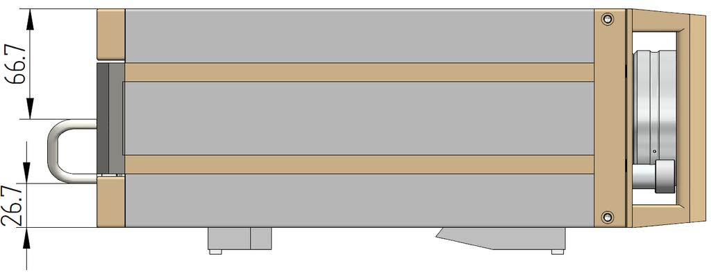
89 12 Drawings Front View Side View 573_MANUAL_E_V3.1 81
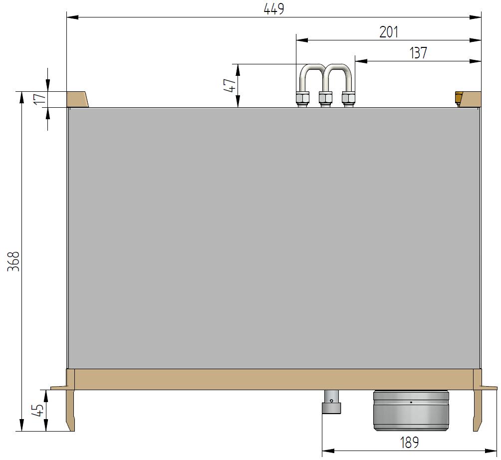
90 Top View _MANUAL_E_V3.1
973-SF 6 Analyzer. Precise and Stable SF 6 Gas Analyzer REFLECTING YOUR STANDARDS
 Precise and Stable SF 6 Gas Analyzer Simultaneous measurement of humidity, SF 6 purity and SO 2 concentration Integrated gas recovery system with automatic pump back Fully automated SF 6 gas testing Fundamental
RAM 4021-DPX Operation Manual
 RAM 4021-DPX Operation Manual Worldwide Manufacturer of Gas Detection Solutions TABLE OF CONTENTS ABL 4021-DPX / RAM 4021-DPX For Your Safety... 3 Description... 3 Setup Mode... 4 Lights/Alarms... 4 Operation...
GasSense NDIR User Manual
 INDEX INDEX... 1 1. OVERVIEW... 2 2. TECHNICAL DATA... 3 3. SPECIFICATIONS... 4 4. PRODUCT DESCRIPTION... 5 4.1 Mechanical details... 5 4.2 Piping... 7 4.3 Connections... 7 5. INSTALLATION... 10 6. CALIBRATION
RAM 4021 Operation Manual
 RAM 4021 Operation Manual Worldwide Manufacturer of Gas Detection Solutions TABLE OF CONTENTS RAM 4021 For your safety...3 Description...3 Set-up mode...4 Annunciator lights/alarms...4 Operation...5 Calibration...6
The HumiSys. RH Generator. Operation. Applications. Designed, built, and supported by InstruQuest Inc.
 The HumiSys RH Generator Designed, built, and supported by InstruQuest Inc. Versatile Relative Humidity Generation and Multi-Sensor System The new HumiSys with single or dual RH probes capabilities is
BI-680 Online Dissolved Oxygen Controller Instruction Manual
 BI-680 Online Dissolved Oxygen Controller Instruction Manual BANTE INSTRUMENTS CO., LTD BI-680 Online Dissolved Oxygen Controller 1 Introduction Thank you for selecting the BI-680 online dissolved oxygen
ACV-10 Automatic Control Valve
 ACV-10 Automatic Control Valve Installation, Operation & Maintenance General: The Archer Instruments ACV-10 is a precision automatic feed rate control valve for use in vacuum systems feeding Chlorine,
RAM Operation Manual. Worldwide Manufacturer of Gas Detection Solutions
 RAM 4021 Operation Manual Worldwide Manufacturer of Gas Detection Solutions TABLE OF CONTENTS RAM 4021 For Your Safety... 2 Description.... 2 Setup Mode.... 2 Lights/Alarms.... 3 Operation.... 4 Calibration....
RAM 4021-PR. Operation Manual. Worldwide Manufacturer of Gas Detection Solutions
 RAM 4021-PR Operation Manual Worldwide Manufacturer of Gas Detection Solutions TABLE OF CONTENTS RAM 4021-PR For Your Safety... 2 Description.... 2 Setup Mode.... 2 Lights/Alarms.... 3 Operation.... 4
Bante810 Benchtop Dissolved Oxygen Meter Instruction Manual
 Bante810 Benchtop Dissolved Oxygen Meter Instruction Manual BANTE INSTRUMENTS CO., LTD Bante810 Benchtop Dissolved Oxygen Meter 1 Introduction Thank you for selecting the Bante810 benchtop dissolved oxygen
RAM Operation Manual
 RAM 4021-1 Operation Manual Worldwide Manufacturer of Gas Detection Solutions TABLE OF CONTENTS RAM 4021-1 For Your Safety... 2 Description... 2 Setup Mode... 3 Lights/Alarms... 3 Operation... 4 Calibration...
Model GFC 7000T CO 2 Analyzer (Addendum to GFC 7000TA Manual, PN 07272)
") Manual Addendum Model GFC 7000T CO 2 Analyzer (Addendum to GFC 7000TA Manual, PN 07272) P/N M07273 DATE 06/11/13 TELEDYNE ELECTRONIC TECHNOLOGIES Analytical Instruments 16830 Chestnut Street City of Industry,
Manual Addendum Model GFC 7000T CO 2 Analyzer (Addendum to GFC 7000TA Manual, PN 07272) P/N M07273 DATE 06/11/13 TELEDYNE ELECTRONIC TECHNOLOGIES Analytical Instruments 16830 Chestnut Street City of Industry,
Pegas 4000 MF Gas Mixer InstructionManual Columbus Instruments
 Pegas 4000 MF Gas Mixer InstructionManual Contents I Table of Contents Foreword Part I Introduction 1 2 1 System overview... 2 2 Specifications... 3 Part II Installation 4 1 Rear panel connections...
RAM Operation Manual. Worldwide Manufacturer of Gas Detection Solutions
 RAM 4021 Operation Manual Worldwide Manufacturer of Gas Detection Solutions TABLE OF CONTENTS RAM 4021 For Your Safety... 2 Description.... 2 Setup Mode.... 2 Lights/Alarms.... 3 Operation.... 4 Calibration....
SDS -Series 4C-D201/-D202 Supplemental Drying System User s Manual
 SDS -Series 4C-D201/-D202 Supplemental Drying System User s Manual 8 Executive Drive P.O. Box 2105 Toms River, NJ 08754 (732) 244-0010 (800) 337-3762 fax (732) 244-8140 www.permapure.com info@permapure.com
Overview. Front Panel: Keypad and Display
 Overview The GA-200B is an analyzer that integrates a gas sampling system with sensors to measure and display the concentrations of oxygen and carbon dioxide in a sample as the percentage of a gas in the
The Univentor 1250 Anaesthesia Unit
 THE UNIVENTOR 1200/1250 ANAESTHESIA UNIT The Univentor 1250 Anaesthesia Unit TABLE OF CONTENTS EDITION 1 Section 1 - WARRANTY & SERVICE 1.1. WARRANTY 2 1.2. DAMAGED SHIPMENTS 2 1.3. SERVICE 2 Section 2
HumiSys HF High Flow RH Generator
 HumiSys HF High Flow RH Generator Designed, built, and supported by InstruQuest Inc. Versatile Relative Humidity Generation and Multi-Sensor System The HumiSys HF is a high flow version of the previously
TANK MANAGER FOR TWO TANKS OPERATING MANUAL. 10/31/11 C-More T6C L color touch panel
 TANK MANAGER FOR TWO TANKS OPERATING MANUAL 10/31/11 C-More T6C L color touch panel 1 TABLE OF CONTENTS GENERAL...3 INSTALLATION...4 STONE TEST PROCEDURE...7 OPERATIONAL SUMMARY...7 AUTO CARBONATION...10
In Vivo Scientific, LLC INSTRUCTION MANUAL
 CO 2 Controller In Vivo Scientific, LLC INSTRUCTION MANUAL CONTENTS CONTENTS...1 ABOUT THIS MANUAL...2 INTRODUCTION...2 Cautions and Warnings...2 Parts List...2 Unpacking...2 INSTRUMENT DESCRIPTION...3
DPC-30 DPC-100. Reference Manual
 DPC-30 DPC-100 Reference Manual 1. Introduction 1.1 Description The Martel DPC Digital Pneumatic Calibrator improves upon traditional dial gauge pneumatic calibrators. The Martel DPC improves accuracy,
Columbus Instruments
 0215-003M Portable O 2 /CO 2 /CH 4 Meter User s Manual Columbus Instruments 950 NORTH HAGUE AVENUE TEL:(614) 276-0861 COLUMBUS, OHIO 43204, USA FAX:(614) 276-0529 1 www.colinst.com TOLL FREE 1-800-669-5011
Model DPC3500 Continuous Low Range Dew Point Analyzer. Operations Manual
 Model DPC3500 Continuous Low Range Dew Point Analyzer Operations Manual Please read, understand, and follow these instructions before operating this equipment. Super Systems, Inc. is not responsible for
RGC-IR Remote Gas Calibrator for IR400
 Remote Gas Calibrator for IR400 The information and technical data disclosed in this document may be used and disseminated only for the purposes and to the extent specifically authorized in writing by
OxyScan Graphic. Operating Instructions. UMS Micro-oxygen sensor 501. Microprocessor instrument
 OxyScan Graphic Operating Instructions UMS Micro-oxygen sensor 501 Microprocessor instrument Introduction Thank you for choosing the UMS Micro Oxygen Sensor 501 - a highly advanced product! Please read
Table of Contents. Sensor Calibration and Troubleshooting CDS4000 CO 2. Introduction 1. Handling Information. Calibration 2.
 FANs 216, 1628.3 Technical Bulletin CDS4000 Issue Date 0797 CDS4000 CO 2 Sensor Calibration and Troubleshooting Table of Contents Introduction 1 Handling Information 1 Calibration 2 Preparation 2 Cautions
Digital Melting Point Apparatus
 Digital Melting Point Apparatus Heating Plateau Ramping Start/Stop Plateau set Ramp stop Hold User Guide Version 1.1 Heating Viewing tube Sample Chamber IEC power inlet socket Power on/off Temperature
INSTRUCTION MANUAL. FLOW CONTROL DRAWERS MANUAL / PLC CONTROL SERIES Model Version Perma Pure LLC Tel:
 PERMA PURE INSTRUCTION MANUAL FLOW CONTROL DRAWERS MANUAL / PLC CONTROL SERIES Model 3300 Version 4.06 Perma Pure LLC Tel: 732-244-0010 P.O. Box 2105, 8 Executive Drive Tel: 800-337-3762 (toll free US)
Calibration Gas Instrument INSTRUCTION MANUAL. Release I. Advanced Calibration Designs, Inc.
 Advanced Calibration Designs, Inc. Calibration Gas Instrument INSTRUCTION MANUAL Release I www.goacd.com Instruction Manual Gas Generator Release I TABLE OF CONTENTS I. General Description Page 2 II. Start-Up
Bante820 Portable Dissolved Oxygen Meter Instruction Manual
 Bante820 Portable Dissolved Oxygen Meter Instruction Manual BANTE INSTRUMENTS CO., LTD Bante820 Portable Dissolved Oxygen Meter 1 Introduction Thank you for selecting the Bante820 portable dissolved oxygen
OEM Manual MODEL 2305 ECONOMICAL DIGITAL SINGLE CYLINDER SCALE
 OEM Manual MODEL 2305 ECONOMICAL DIGITAL SINGLE CYLINDER SCALE 1 These instructions generally describe the installation, operation, and maintenance of subject equipment. The manufacturer reserves the right
MP15 Jockey Pump Controller
 Setup and Operating Instructions MP15 Jockey Pump Controller This manual provides general information, installation, operation, maintenance, and system setup information for Metron Model MP15 Jockey Pump
92831 TEL: (714) FAX:
 FAX:") Document N0. 1800-03 Copyright 2010 Terra Universal Inc. All rights reserved. Revised Sept. 2010 Terra Universal, Inc. TerraUniversal.com 800 S. Raymond Ave. Fullerton, CA 92831 TEL: (714) 578-6000 FAX:
Document N0. 1800-03 Copyright 2010 Terra Universal Inc. All rights reserved. Revised Sept. 2010 Terra Universal, Inc. TerraUniversal.com 800 S. Raymond Ave. Fullerton, CA 92831 TEL: (714) 578-6000 FAX:
SPECIFICATIONS APCEPH1
 APCEPH1 ph CONTROLLER SPECIFICATIONS APCEPH1 Input voltage 120 Volts AC Maximum amperage 14.5 amps @ 120 VAC ph Accuracy +/- 0.2 ph ph Control range Adjustable 4.5 8.5 ph Weight < 1 lbs Dimensions 3" x
A4s Operation Manual
 A4s Operation Manual Safety Instruction Please read this manual carefully, also with related manual for the machinery before use the controller. For installing and operating the controller properly and
Basic Nitriding Sampling System Hydrogen Analyzer with Calculated % DA, % NH 3, and K N Values. Operations Manual
 Basic Nitriding Sampling System Hydrogen Analyzer with Calculated % DA, % NH 3, and K N Values Operations Manual Please read, understand, and follow these instructions before operating this equipment.
CSA Sample Draw Aspirator Adapter Operator s Manual
 30-0951-CSA Sample Draw Aspirator Adapter Operator s Manual Part Number: 71-0367 Revision: 0 Released: 4/30/15 www.rkiinstruments.com WARNING Read and understand this instruction manual before operating
UNITY 2 TM. Air Server Series 2 Operators Manual. Version 1.0. February 2008
 UNITY 2 TM Air Server Series 2 Operators Manual Version 1.0 February 2008 1. Introduction to the Air Server Accessory for UNITY 2...2 1.1. Summary of Operation...2 2. Developing a UNITY 2-Air Server method
A4 Operation Manual. Fig.1-1 Controller Socket Diagram
 A4 Operation Manual Safety Instruction Please read this manual carefully, also with related manual for the machinery before use the controller. For installing and operating the controller properly and
User's Manual. Heavy Duty Dissolved Oxygen Meter. Model
 User's Manual Heavy Duty Dissolved Oxygen Meter Model 407510 Introduction Congratulations on your purchase of Extech's Heavy Duty Dissolved Oxygen / Temperature Meter which simultaneously displays Dissolved
E2K-L. Liquid Level Sensor That Is Unaffected by the Color of the Pipe or Liquid. Liquid Level Sensor. Ordering Information
 Liquid Level EK-L CSM_EK-L_DS_E 3 Liquid Level That Is Unaffected by the Color of the or Liquid Mount to bypass pipes. Fit a wide range of pipe diameters: 8 to mm or to mm Built-in Amplifiers to save space.
OXY Integral. INTERCON ENTERPRISES INC Tel: Fax: Internet:
 OXY Integral INTERCON ENTERPRISES INC Tel: 800 665 6655 Fax: 604 946 5340 E-Mail: sales@intercononline.com Internet: www.intercononline.com Manual Integral 2006 1 INDEX 2-3 PREFACE 4 INTRODUCTION 5 Principle
! Warning, refer to accompanying documents.
 About this Manual To the best of our knowledge and at the time written, the information contained in this document is technically correct and the procedures accurate and adequate to operate this instrument
Psyclone TM. Protimeter Thermo-Hygrometer. GE Sensing. Operating Manual. INS7800, Rev. A (September 2007)
") GE Sensing Psyclone TM Protimeter Thermo-Hygrometer Operating Manual INS7800, Rev. A (September 2007) Psyclone is a Protimeter product. Protimeter has joined other GE high-technology sensing businesses
GE Sensing Psyclone TM Protimeter Thermo-Hygrometer Operating Manual INS7800, Rev. A (September 2007) Psyclone is a Protimeter product. Protimeter has joined other GE high-technology sensing businesses
User s Guide Temperature Sensor Converter TSC-599
 User s Guide Temperature Sensor Converter TSC-599 ILX Lightwave Corporation 31950 Frontage Road Bozeman, MT, U.S.A. 59715 U.S. & Canada: 1-800-459-9459 International Inquiries: 406-556-2481 Fax 406-586-9405
Do Not Print This Page.
 Do Not Print This Page. Load 1 sheet of cardstock paper. Print Page 2 - the cover For the body of the text, load 3 sheets of 28lb matte finish paper into the printer. Print pages 3, 5, 7 (Sheet 1, 2, 3)
BAROMETER PRESSURE STANDARD PRESSURE CONTROLLER
 BAROMETER PRESSURE STANDARD PRESSURE CONTROLLER Features ±0.01% FS Measurement & Control Accuracy ±0.001% /ºC Thermal Stability Pressure Ranges from ±1 psid to 1200 psia Applications Barometric Measurement
BGA244 Binary Gas Analyzer
 Quick Start Guide Revision 1.0 Certification Warranty Service certifies that this product met its published specification at the time of shipment. This product is warranted against defects in materials
GE Measurement & Control
 GE Measurement & Control Psyclone Protimeter Thermo-Hygrometer Operating Manual INS7800, Rev. C August 2013 Psyclone is a Protimeter product. Protimeter has joined other GE high-technology sensing businesses
FTC130 Transmitter. Operating Manual
 Seite 1 von 11 FTC130 Transmitter Fast Thermal Conductivity Analyzer Operating Manual 1.09KD180724CWI1V05 Messkonzept GmbH Seite 2 von 11 1. Intended Use... 3 2. Description... 4 3. Measuring gases and
OEM Manual. MODEL ½ Digit DRUM SCALE
 OEM Manual MODEL 4020-3 ½ Digit DRUM SCALE Scaletron Industries, Ltd. Bedminster Industrial Park 53 Apple Tree Lane P.O. Box 365 Plumsteadville, PA 18949 USA Toll Free: 1-800-257-5911 (USA & Canada) Phone:
Model 130M Pneumatic Controller
 Instruction MI 017-450 May 1978 Model 130M Pneumatic Controller Installation and Operation Manual Control Unit Controller Model 130M Controller is a pneumatic, shelf-mounted instrument with a separate
Oxygen Concentrator. Installation and Operation Manual. ClearWater Tech, LLC. Integrated Ozone Systems
 Oxygen Concentrator Installation and Operation Manual ClearWater Tech, LLC. Integrated Ozone Systems 850-E Capitolio Way, San Luis Obispo, Ca 93401 805-549-9724 Fax: 805-549-0306 E-mail: service@cwtozone.com
JOLLY2. Installation user s manual. 6 different operating modes selectable. version 3.3. DATA TO BE FILLED OUT BY THE INSTALLER (Page 1)
") ENGLISH ENGLISH ENGLISH ENGLISH Installation user s manual Warning! electrical scheme modified JANUARY 2005 version 3.3 JOLLY2 DATA TO BE FILLED OUT BY THE INSTALLER (Page 1) 6 different operating modes
ENGLISH ENGLISH ENGLISH ENGLISH Installation user s manual Warning! electrical scheme modified JANUARY 2005 version 3.3 JOLLY2 DATA TO BE FILLED OUT BY THE INSTALLER (Page 1) 6 different operating modes
Cover Page for Lab Report Group Portion. Pump Performance
 Cover Page for Lab Report Group Portion Pump Performance Prepared by Professor J. M. Cimbala, Penn State University Latest revision: 02 March 2012 Name 1: Name 2: Name 3: [Name 4: ] Date: Section number:
Appendix D: SOP of INNOVA 1412 Photoacoustic Multi-Gas Monitor. Description and Principle of Operation
 Page 1 of 19 : SOP of INNOVA 1412 Photoacoustic Multi-Gas Monitor Description and Principle of Operation The photoacoustic multi-gas monitor (INNOVA 1412, Innova AirTech Instruments, Denmark) is a highly
BUBBLER CONTROL SYSTEM
 BUBBLER CONTROL SYSTEM Description: The HDBCS is a fully automatic bubbler system, which does liquid level measurements in water and wastewater applications. It is a dual air compressor system with, air
Transmitter CS 21 Operation Manual
 Transmitter CS 21 Operation Manual Content Page For your Safety 3 General Description 3 Detection Principle 4 Operational Notes 4 Design 4 Mounting Position of CS21 5 Mounting 6 Installation of Electrical
Digital Vacuum Regulator
 Temperature Control for Research and Industry Digital Vacuum Regulator User s Manual Model 300 INDEX SECTION PAGE 1. QUICK OPERATING INSTRUCTIONS........................... 3 Safety Notices.................................................
Instruction Manual 742 5/1/2009. Eclipse Ratio Regulators ES Series Version 1
 Instruction Manual 742 5/1/2009 Eclipse Ratio Regulators ES Series Version 1 Copyright Copyright 1997 by Eclipse, Inc. All rights reserved worldwide. This publication is protected by federal regulation
L 100. Bubble-Tube Level System. Installation, Operation and Maintenance Instructions
 L 100 Bubble-Tube Level System Installation, Operation and Maintenance Instructions Figure 1 Contents Section Description Page 1.0 Introduction 2 2.0 Specifications 3 3.0 Installation 3 4.0 Warranty 6
AUTOMATIC TIRE INFLATOR # MW-60, MW-60-4WAY & MW-64HP
 USER MANUEL AUTOMATIC TIRE INFLATOR # MW-60, MW-60-4WAY & MW-64HP TIRE EQUIPMENT MANUFACTURER 1.866.409.RACK WWW.MARTINSINDUSTRIES.COM info@martinsindustries.com PARTS Verify that the following components
Instruction Manual. BZ7002 Calibration Software BE
 Instruction Manual BZ7002 Calibration Software BE6034-12 Index _ Index Index... 2 Chapter 1 BZ7002 Calibration Software... 4 1. Introduction... 5 Chapter 2 Installation of the BZ7002... 6 2. Installation
Transmitter CS 21 Operation Manual
 Transmitter CS 21 Operation Manual 1194 Oak Valley Drive, Suite 20, Ann Arbor, MI 48108 800-959-0573 734-769-1888 Content Page For your Safety 3 General Description 3 Detection Principle 4 Operation 4
Pneumatic high-pressure controller Model CPC7000
 Calibration technology Pneumatic high-pressure controller Model CPC7000 WIKA data sheet CT 27.63 Applications Healthcare and avionics industry Industry (laboratory, workshop and production) Transmitter
Digital Vacuum Regulator
 Temperature Control for Research and Industry Digital Vacuum Regulator User s Manual Model DVR-380 INDEX SECTION PAGE SAFETY NOTICES................................................. 3 1. QUICK OPERATING
INSTRUCTION MANUAL MP4AR Remote Convection Gauge Range: 1 x 10⁻³ Torr to 1 x 10+3 Torr
 INSTRUCTION MANUAL MP4AR Remote Convection Gauge Range: 1 x 10⁻³ Torr to 1 x 10+3 Torr A DIVISION OF THE FREDERICKS COMPANY 2400 PHILMONT AVE. HUNTINGDONVALLEY, PA 19006 PARTS LIST 1 3 4 2 # QTY ITEM DESCRIPTION
with O 2 Controller Instruction Manual
 14500 Coy Drive, Grass Lake, Michigan 49240 734-475-2200 E-mail: sales@coylab.com www.coylab.com Hypoxic Cabinets (In-Vivo / In-Vitro) with O 2 Controller Instruction Manual Index Page Warranty 2 Warnings
SPS-5. Rate Computing Scale. Operation Manual
 SPS-5 Rate Computing Scale Operation Manual Revision 1.0 October 17, 1996 1996 Transcell Technology, Inc. Contents subject to change without notice. Transcell Technology, Inc. 975 Deerfield Parkway Buffalo
MODEL 6600 Rev. B4 USER'S MANUAL LAVERSAB INC., 505 GILLINGHAM LANE. SUGAR LAND TX (281) FAX: (281)
 FAX: (281)") MODEL 6600 Rev. B4 USER'S MANUAL LAVERSAB INC., 505 GILLINGHAM LANE. SUGAR LAND TX 77478 (281) 325-8300 FAX: (281) 325-8399 Email: aservice@laversab.com Document Number : 9051 REV B4 Date: June 07, 2011.
MODEL 6600 Rev. B4 USER'S MANUAL LAVERSAB INC., 505 GILLINGHAM LANE. SUGAR LAND TX 77478 (281) 325-8300 FAX: (281) 325-8399 Email: aservice@laversab.com Document Number : 9051 REV B4 Date: June 07, 2011.
SomnoSuite FAQ. Setup. Calibration 4. What are the calibration requirements for the SomnoSuite? Settings
 SomnoSuite FAQ V1.3 January 2015 Setup 1. How do I connect the SomnoSuite to my oxygen source? 2. Is there a way to speed up the downward movement of the pusher block when setting the empty position? 3.
Manual of SF6 Comprehensive Tester
 Manual of SF6 Comprehensive Tester Important Description All the staff taking in charge of the usage or maintenance of this product should carefully read this manual. The same as any other complicated
DOscan10 Pocket Dissolved Oxygen Tester Instruction Manual
 DOscan10 Pocket Dissolved Oxygen Tester Instruction Manual BANTE INSTRUMENTS CO., LTD DOscan10 Pocket Dissolved Oxygen Tester 1 Thank you for selecting the DOscan10 pocket dissolved oxygen tester. This
UNIVERSAL MASK TEST SYSTEM
 f UNIVERSAL MASK TEST SYSTEM Quotation #110811 Automated Motion Inc. 225 NW Victoria Drive Lee s Summit, Missouri 64086-4709 www.automatedmotion.com SYSTEM OVERVIEW AMI s Universal Mask Test System is
Roller AC Servo System
 Safely Instruction Roller AC Servo System HMI-15 User Manual Please read this manual carefully, also with related manual for the machinery before use the controller. For installing and operating the controller
Measurement accessories METPOINT OCV for the measurement in systems up to 40 bar
 EN - english Instructions for installation and operation Measurement accessories METPOINT OCV for the measurement in systems up to 40 bar Dear customer, Thank you for deciding in favour of the METPOINT
Constant Pressure Inlet (CCN) Operator Manual
 Operator Manual") Constant Pressure Inlet (CCN) Operator Manual DOC-0125 Revision J 2545 Central Avenue Boulder, CO 80301-5727 USA C O P Y R I G H T 2 0 1 1 D R O P L E T M E A S U R E M E N T T E C H N O L O G I E S, I
Constant Pressure Inlet (CCN) Operator Manual DOC-0125 Revision J 2545 Central Avenue Boulder, CO 80301-5727 USA C O P Y R I G H T 2 0 1 1 D R O P L E T M E A S U R E M E N T T E C H N O L O G I E S, I
Application Note AN-107
 SPEC Sensor TM Characterization & Calibration Considerations Scope This document is provided to describe the considerations needed to characterize, calibrate, verify and validate the measurement performance
Bante821 Portable Dissolved Oxygen Meter Instruction Manual
 Bante821 Portable Dissolved Oxygen Meter Instruction Manual BANTE INSTRUMENTS CO., LTD Bante821 Portable Dissolved Oxygen Meter 1 Introduction Thank you for selecting the Bante821 portable dissolved oxygen
AMT-Ex Dewpoint Transmitter
 AMT-Ex Dewpoint Transmitter Instruction Manual Alpha Moisture Systems Alpha House 96 City Road Bradford BD8 8ES England Tel: +44 1274 733100 Fax: +44 1274 733200 email: mail@amsytems.co.uk web: www.amsystems.co.uk
TEL/jlRE" Introduction. Display Features and Modes. Startup Procedure. Power-Up Procedure. Adjustment Modes
 TEL/jlRE" Introduction The Telaire 7001 CO 2 /T emperature monitor (shown in Fi gt u e 1 below) is an easy to use hand-held instnunent, which provides stable and highly accurate readings due to Telaire
WELCOME TO THE REVOLUTION
 USER GUIDE WELCOME TO THE REVOLUTION THANK YOU FOR CHOOSING THE GCQUAD We listened to what you wanted - and created the most accurate, versatile and game-enhancing ball and club analysis solution available
This test shall be carried out on all vehicles equipped with open type traction batteries.
 5.4. Determination of hydrogen emissions page 1 RESS-6-15 5.4.1. This test shall be carried out on all vehicles equipped with open type traction batteries. 5.4.2. The test shall be conducted following
UBEC 1AT. AUTO TANK Fill System Installation, Operation, & Setup Instructions
 Document Number: XE-ATA5PM-R1A UBEC 1AT AUTO TANK Fill System 08899155 Installation, Operation, & Setup Instructions Rev170906-EB-FRC PHYSICAL: 1302 WEST BEARDSLEY AVE ELKHART, IN 46514 WWW.ELKHARTBRASS.COM
DF-550E PROCESS ANALYSERS APPLICATIONS FEATURES
 PROCESS ANALYSERS DF-550E The DF-550E Nano Trace oxygen analyser is a Coulometric sensor based analyser designed to measure oxygen as a contaminant at ultra trace levels in ultra high purity electronic
Mini-Pro CO2 Sensor User s Manual - ANALOG MODEL -
 Mini-Pro CO2 Sensor User s Manual - ANALOG MODEL - Table of Contents 1. Introduction 3 2. Instrument Setup 4 2.1 Instrument Checklist 4 2.2 Optional Accessories 4 2.3 Gas Concentration Ranges Available
NOVALYNX CORPORATION MODEL WEATHER STATION INSTRUCTION MANUAL
 NOVALYNX CORPORATION MODEL 100-1950 WEATHER STATION INSTRUCTION MANUAL Receiving and Unpacking Carefully unpack all components and compare to packing list. Notify NovaLynx Corporation immediately concerning
HI 2314 HI 2315 HI 23151
 Instruction Manual HI 2314 HI 2315 HI 23151 Multi-Range Conductivity Meters for Laboratories www.hannainst.com Dear Customer, Thank you for choosing a Hanna Instruments product. Please read this instruction
WSN: XXXXXX 101 ROME COURT FORT COLLINS, CO, PHONE #: (970) FAX #: (970) TO-Clean Manual
 FAX #: (970) TO-Clean Manual") WSN: XXXXXX 101 ROME COURT FORT COLLINS, CO, 80524 PHONE #: (970) 221-9179 FAX #: (970) 221-9364 TO-Clean Manual Copyright 2008 by Wasson ECE Instrumentation, Inc. (SJC 02/05/2008) All rights reserved
WSN: XXXXXX 101 ROME COURT FORT COLLINS, CO, 80524 PHONE #: (970) 221-9179 FAX #: (970) 221-9364 TO-Clean Manual Copyright 2008 by Wasson ECE Instrumentation, Inc. (SJC 02/05/2008) All rights reserved
ASE SOLVENT CONTROLLER INSTALLATION INSTRUCTIONS Dionex Corporation
 ASE SOLVENT CONTROLLER INSTALLATION INSTRUCTIONS 2000 Dionex Corporation Document No. 031277 Revision 03 April 2000 2000 Dionex Corporation All rights reserved worldwide. Printed in the United States of
ENVIRONMENTAL INSTRUMENTS, LLC
 Model FL-3A Fluoroprobe ENVIRONMENTAL INSTRUMENTS, LLC 144 Industrial Park Drive Suite A-3 Waynesville, NC 28723 Phone: 828-452-7776 www.thefluoroprobe.com Changing the way the world measures oxygen O
Portable Gas Monitor GX User Maintenance Manual (H4-0050)
") H4E-0050 Portable Gas Monitor GX-8000 User Maintenance Manual (H4-0050) Need of Maintenance and Servicing This gas monitor must be maintained in a normal state at all times to prevent accidents due to
H4E-0050 Portable Gas Monitor GX-8000 User Maintenance Manual (H4-0050) Need of Maintenance and Servicing This gas monitor must be maintained in a normal state at all times to prevent accidents due to
Manual Weighingblock VB2 series and Uniscale
 Manual Weighingblock VB2 series and Uniscale Note: At page 8 in this manual you will find a short form instruction. Normally the only instruction shipped together with the Scale. Overview different ranges.
Model : LMW-9620 Please read this manual carefully before using the instrument Labnics Equipment
 MICROPLATE WASHER User Manual Model : LMW-9620 Please read this manual carefully before using the instrument Labnics Equipment Table of Content Sr.No. Contents Pg. No. 1 INTRODUCTION 1 1.1 Working Conditions
Advanced Test Equipment Rentals ATEC (2832)
") WARRANTY CLAUSE METROSONICS warrants each new cl-304 manufactured and sold to be free from defects in material, workmanship and construction, except for batteries which may be contained therein, and that
WARRANTY CLAUSE METROSONICS warrants each new cl-304 manufactured and sold to be free from defects in material, workmanship and construction, except for batteries which may be contained therein, and that
Operating Instructions Part No
 DIGITAL AUTOMATIC TYRE INFLATOR Operating Instructions Part No. 11.0578 Thank you for selecting this Jamec Pem Automatic Tyre Inflator. Please read this manual before carrying out any installation or service
OWNER S MANUAL NMB SERIES
 OWNER S MANUAL NMB SERIES NMB Manual V2.0.doc 1. PARTS IDENTIFICATION LIST 1. 5. 2. 4. 3. 6(a). 6(b). Figure 1.1 1. Powerpack with timer option (x1) 2. Cell (x1) 3. Cell Housing (x1) 4. O-ring (x1) 5.
Met One E-BAM Particulate Monitor
 STANDARD OPERATING PROCEDURES Met One E-BAM Particulate Monitor AMBIENT AIR MONITORING PROGRAM for the 130 LIBERTY STREET DECONSTRUCTION PROJECT LOWER MANHATTAN DEVELOPMENT CORPORATION 1 Liberty Plaza
Pressure Automated Calibration Equipment
 GE Measurement & control Pressure Automated Calibration Equipment Safety Instructions and User Guide - K0447 PACE5000 PACE6000 K0447 Issue No. 9 1 10 1 PACE5000 1 2 3 4 5 PACE6000 2 6 7 8 3 4 5 6 7 8 9
BUBBLER CONTROL SYSTEM
 BUBBLER CONTROL SYSTEM Description: The LDBCS is a fully automatic bubbler system, which does liquid level measurements in water and wastewater applications. It is a dual air compressor system with, air