TECHNICAL DATA SECTION G
|
|
|
- Lawrence Jordan Norris
- 5 years ago
- Views:
Transcription


1 TECHNICAL DATA SECTION pirtekusa.com
2 Center PRODUCT INQUIRY Page 1 of 2 Please send this completed form to: customerservice@pirtekusa.com OR Fax to (321) Contact Person Pictures Sent Yes No Date Sent Date SIZE TEMPERATURE Temperature of Medium Environmental Temp Industry Dash Size Comments on Temperature Please add comments on temperature here. F C F C Please attach any photos or dimensional sketches of the products requested with this form, this helps with clairifying request. APPLICATION Consider (but not limited to) whether the component is indoor or outdoor, bend radius, movement, types of conditions, type of machine or equipment, what the product is intended for, etc. Be as descriptive as possible to convey what the hose / item will be subjected to below. MEDIUM CONVEYED If the medium is more complex and no MSDS is attached, please provide as much information as possible. TECHNICAL DATA PRODUCT ENQUIRY Comments on Medium Please add specific details pertaining to medium here. PRESSURE RECOMMENDED FLOW Operating Pressure PSI BAR PM Peak Pressure PSI BAR VACUUM / SUCTION Mercury (in/hg) Comments on Pressure, Suction or Flow Please add specific details pertaining to pressure, suction or flow here. 1
3 TECHNICAL DATA PRODUCT ENQUIRY Please send this completed form to: OR Fax to (321) ENDS Industry Dash Size Thread Type Fitting/Adapter Angle ( ) Suggested Part No. / Vendor Material Comments on Ends Please add specific details pertaining to ends here. DELIVERY Date product is required Comments on Delivery Please add specific details pertaining to delivery here. ADDITIONAL INFORMATION REARDIN INQUIRY PRODUCT INQUIRY Page 2 of 2 2 2
4 Recommended Practices for Hydraulic Hose Assemblies SAE J Foreword This SAE Recommended Practices is intended as a guide to consider when selecting, routing, fabricating, installing, replacing, maintaining, and storing hose for fluid-power systems. It is subject to change to keep pace with experience and technical advances. For those new to hose use in fluid power systems, this guide outlines practices to note during each phase of system design and use. Experienced designers and users skilled in achieving proper results, as well as the less experienced, can use this outline as a list of considerations to keep in mind. Fluid power systems are complex and require extensive knowledge of both the system requirements and the various types of hose. Therefore, all inclusive, detailed, step by step instructions are not practical and are beyond the scope of this document. Less experienced designers and users who need more information can consult specialists such as hose suppliers and manufacturers. This guide can improve the communication process. Safety Considerations These recommended practices involve safety considerations; note these carefully during all phases of design and use of hose systems. Improper selection, fabrication, installation, or maintenance of hose and hose assemblies for fluid power systems may result in serious personal injury or property damage. These recommended practices can reduce the likelihood of component or system failure, thereby reducing the risk of injury or damage. 1. Scope SAEJ1273 provides guidelines for selection, routing, fabrication, installation, replacement, maintenance, and storage of hose and hose assemblies for fluid-power systems. Many of these SAE Recommended Practices also may be suitable for other hoses and systems. 2. Reference 2.1 Applicable publications The following publications form a part of this specification to the extent specified herein. Unless otherwise specified, the latest issue of SAE publications shall apply SAE publications Available for SAE, 400 Commonwealth Drive, Warrendale, PA SAEJ343 Test and Procedures for SAE 100 R Series Hydraulic Hose and Hose Assemblies SAEJ514 Hydraulic Tube Fittings SAEJ517 Hydraulic Hose SAEJ1927 Cumulative Damage Analysis for Hydraulic Hose Assemblies ISO publications Available from ANSI, 11 West 42nd Street, New York, NY ISO 3457 Earth moving machinery uards and shields definitions and specifications. 3. Definitions These explanations serve only to clarify this document and are not intended to stand alone. They are presented sequentially, with the former helping to explain the latter. 3.1 fluid power Energy transmitted and controlled using pressurised hydraulic fluids or compressed air. 3.2 Hose flexible conductor. In this document, the term hose also may refer to a hose assembly with related accessories used in fluid power applications. 3.3 Hose fitting or fitting connector which can be attached to the end of a hose. 3.4 Hose assembly hose with hose fittings attached. 3.5 Hose failure occurrence in which a hose stops meeting system requirements. 3.6 Hose service life length of time a hose meets system requirements without needing replacement. 4. Safety considerations listed in 4.1 to 4.5 are some potential conditions and situations that may lead to personal injury and/or property damage. This list is not necessarily all inclusive. Consider reasonable and feasible means, including those described in this section, to reduce the risk of injuries or property damage. Training, including the information in this document, for operators, maintenance personnel, and other individuals working with hoses under pressure is encouraged. 4.1 Fluid injections fine streams of escaping pressurised fluid can penetrate skin and enter a human body. These fluid injections may cause severe tissue damage and loss of limb. Consider various means to reduce the risk of fluid injections, particularly in areas normally occupied by operators. Consider careful routing, adjacent components, warnings, guards, shields, and training programs. Relieve pressure before disconnecting hydraulic or other lines. Tighten all connections before applying pressure. Avoid contact with escaping fluids. Treat all leaks as though pressurised and hot enough to burn skin. Never use any part of your body to check a hose for leaks. If a fluid-injection accident occurs, see a doctor immediately. DO NOT DELAY OR TREAT AS A SIMPLE CUT! Any fluid injected into skin must be surgically removed within a few hours or gangrene may result. Doctors unfamiliar with this type of injury should consult a knowledgeable medical source. 4.2 Whipping hose if a pressurised hose assembly blows apart, the fittings can be thrown off at high speed, and the loose hose can flail or whip with great force. This is particularly true in compressible-fluid systems. When the risk exists, consider guards and restraints to protect against injury. 4.3 Burns from conveyed fluids fluid-power media may reach temperatures that can burn human skin. If there is risk of burns from escaping fluid, consider guards and shields to prevent injury, particularly in areas normally occupied by operators. 4.4 Fire and explosions from conveyed fluids most fluid-power media, including fire-resistant hydraulic fluids, will burn under certain conditions. Fluids which escape from pressurised systems may form a mist or fine spray which can flash or explode upon contact with an ignition source. Consider selecting, guarding, and routing hose to minimise the risk of combustion (see Section 5 and ISO 3457). 4.5 Fire and explosions from static-electric discharge fluid passing through hose can generate static electricity, resulting in static-electric discharge. This may create sparks that can ignite system fluids or gases in the surrounding atmosphere. When this potential exists, select hose specifically designed to carry the static-electric charge to ground. TECHNICAL DATA SAE SPECIFICATION 3
5 TECHNICAL DATA SAE SPECIFICATION (R) Test and Test Procedures for SAE 100R Series Hydraulic Hose and Hose Assemblies SAE J343 July 2001 This document is technically equivalent to ISO 6605 except, as noted in the foreword. Foreword this document has not changed other than to put it into the new SAE technical standards board format. SAE J343 has been revised to be technically equivalent to ISO 6605, except that additional tests in paragraphs 4.9 to 4.14 were included. 1. Scope this SAE standard gives methods for testing and evaluation performance of the SAE 100R series of hydraulic hose and hose assemblies (hose and attached end fittings) used in hydraulic fluid power systems. Specific tests and performance criteria for evaluating hose assemblies used in hydraulic service are in accordance with the requirements for hose in the respective specifications of SAE J517. This document further establishes a uniform means of testing and evaluating performance of hydraulic hose assemblies. 2. Reference 2.1 Applicable publications The following publications form a part of the specification to the extent specified herein. Unless otherwise indicated the latest revision of SAE publications shall apply SAE Publications available from SAE, 400 Commonwealth Drive, Warrendale, PA SAE J517 Hydraulic hose ASTM publications available from ASTM, 100 Barr Harbor Drive, West Conshohocken, PA ASTM D 380 standard methods of testing rubber hose ISO publications available from ANSI, 11 West 42nd Street, New York, NY ISO 3448 industrial liquid lubricants-iso viscosity classification ISO 6605 hydraulic fluid-power hose assemblies method of test. 3. Test procedures The test procedures described in the current issue of ASTM D 380 shall be followed. However, in cases of conflict between the ASTM specifications and those described as follows, the latter shall take precedence. Unless otherwise specified in this document, or other SAE standards, tests shall be conducted at the prevailing ambient temperature of the testing facility. 4. Standard test warning water or another liquid suitable for the hose under test shall be used as the test medium. The use of air and other gaseous materials as testing media should be avoided because of the risk to operators. In special cases where such media are required for the tests, strict safety measures are imperative. Furthermore, it is stressed that when a liquid is used as the test medium, it is essential that all air is expelled from the test piece because of the risk of injury to the operator due to the sudden expansion of trapped air released when the hose bursts Dimensions check test The hose shall be inspected for conformity to all dimensions tabulated in the applicable specification. Determine finished outside diameters and reinforcement diameters, where required, by calculation from measurement of the respective circumference. As an alternative, use a flexible tape graduated to read the diameter directly. Measure the inside diameter by means of a suitable expanding ball or telescoping gauge. Measure concentricity over both the reinforcement and the finished outside diameters using either a dial indicator gauge or a micrometer. Round the foot of the measuring instrument to conform to the inside diameter of the hose. Take reading at 90 degree intervals around the hose. NOTE: Acceptability is based on the total variation between the high and low readings. Take inside and outside diameter measurements at a minimum of 1 inch from the hose ends and concentricity measurements at a minimum of 1/2 inch from the hose ends. 4.2 Proof test Test the hose assemblies hydrostatically to the specified proof pressure for a period of not less than 30 s nor more than 60 s. There shall be no indication of failure or leakage. 4.3 Change in length test Conduct measurements for the determination of elongation or contraction on a previously untested, unaged hose assembly having at least 24 ins length of free hose between hose fittings. Attach the hose assembly to the pressure source in an unrestricted straight position. If the hose is not straight due to its natural curvature, it may be fastened laterally to achieve a straight position. Pressurise to the specified operating pressure for a period of 30 s, then release the pressure. Place accurate reference marks 20 ins apart on the outer cover of the hose, midway between fittings, after allowing the hose assembly to restabilise for a period of 30 s, following pressure release. Repressurise the hose assembly to the specified operating pressure for a periods of 30 s. Measure the final length while the hose is pressurised. The final length is the distance between reference marks while the hose is pressurised. Complete the determination of the change in length using Equation 1: l 1 l 0 l = x 100 l 0 (Eq.1) where: l is the distance between the reference marks when the hose was not pressurised following the initial pressurisation; l 1 is the distance between the reference marks under pressure; l is the percentage change in length, which will be position (+) in the case of an increase in length and negative ( ) in the case of a decrease in length. 4.4 Burst test Subject unaged hose assemblies, on which the end fittings have been attached for not more than 30 days, to a hydrostatic pressure, increased at a constant rate so as to attain the specified minimum burst pressure within a period of not less than 15 s more than 60 s. Reject hose assemblies showing leakage, hose burst or indication of failure below the specified minimum burst pressure. NOTE: This is a destructive test. Assemblies which have been subjected to this test shall be destroyed. 4.5 Cold bend test subject hose assemblies to the specified temperature in a straight position for 24 h. Then, while still at the specified temperature, the samples shall be evenly and uniformly bent once over a mandrel having a diameter equal to twice the specified minimum bend radius. Bending shall be accomplished within a period of not less than 8 s nor more than 12 s. In the case of hose sizes up to and including 7/8 inch nominal inside diameter, bend them through 180 degrees over the mandrel; in the case of hose sizes larger than 7/8 inch nominal inside diameter, bend them through 90 degrees over the mandrel. After bending, allow the sample to warm to room temperature, visually examine it for cover cracks and subject it to the proof test. There shall be no cover cracks or leakage. (In lieu of the bending test, hoses larger than 7/8 inch nominal inside diameter may be considered acceptable if samples of tube and cover pass the Low Temperature Test on Tube and Cover of ASTM D 380). Reject any samples with visible cracks of leakage. NOTE: This is a destructive test. Assemblies which have been subjected to this test shall be destroyed. 4.6 Impulse test test for unaged hose assemblies with end fittings which have been attached for not more than 30 days. Where the individual standard requires, also test aged hose assemblies. Apply a pulsating pressure internally to the hose assemblies at a rate between 0.5 and 1.34 Hz; record the frequency used. The pressure cycle shall fall within the shaded areas of Figure 1 of SAE J343 and conform as closely as possible to the curve shown. Select a test fluid which complies with the requirements of ISO V 46± 4.6 at 104 F per ISO 3448, and circulate it at a rate sufficient to 4
6 maintain a uniform fluid temperature within the hose assemblies. Other fluids may be used as agreed upon between the customer and the manufacturer. Calculate the free (exposed) length of hose under test, shown on Figure 2, as follows: a. Hose sizes up to and including 7/8 inch nominal inside diameter (see Equation 3): 180 degrees bend free length = πr+2d (Eq.3) b. Hose sizes larger than 7/8 inch nominal inside diameter (see Equation 4): where: 90 degrees bend free length = π 2 r+2d (Eq.3) r = minimum bend radius d = hose outside diameter Connect the test pieces to the apparatus. The test pieces shall be installed according to Figure 2 of SAE J343. Test pieces of hose of nominal inside diameter up and including 7/8 inch shall be bent through 180 degrees and hoses of nominal inside diameter larger than 7/8 inch shall be bent through 90 degrees. Test the hose at the impulse test pressure indicated in the individual specification. The test fluid shall be circulated through the assemblies at the specified temperature with a tolerance of 37.4 F. Cooling or heating of the test chamber shall not be permitted, except when individual standards require testing with synthetic base test fluids at a temperature higher than 302 F. When such higher temperatures are required, the impulse test fluid need not be circulated if both the fluid and the assemblies are externally heated in the test chamber, at the specified temperature with a tolerance of 41 F. Determine the duration of the impulse test in total number of cycles by the individual standard for the hose assemblies. Where aged samples are required, refer to the individual standards. It is recommended the test fluid be changed frequently to prevent breakdown. NOTE: This is a destructive test. Assemblies which have been subjected to this test shall be destroyed. 4.7 Leakage test Subject unaged hose assemblies, on which the end fitting have been attached for not more than 30 days, to a hydrostatic pressure of 70% of the specified minimum burst pressure for a period of between 5.0 to 5.5. min. Reduce the fluid pressure to 0 PSI. Re-apply the 70% of minimum burst hydrostatic pressure for another 5.0 to 5.5 min period. Reject assemblies showing leakage or failure. NOTE: This is a destructive test. Assemblies which have been subjected to this test shall be destroyed. A mercury or salt water solution electrode shall be provided at the upper end as shown, by inserting a non-meticallic plug with an O-ring seal to distance of 3 inches from the end of the tubing, thus providing an average test length of 10 inches. Mercury or salt water solution shall then be added to a level 1 inch above the plug. Any suitable conductor to this electrode may be used, including a threaded end attached to the plug if so desired. Concentration of salt water, if used, shall be 60 oz NaCI per gallon of H V DC shall be applied between the upper electrode and the lower electrode (adapter or male fitting hex). The current shall be measured with an instrument with a sensitivity of at least 1 µa(1 x 10 6 A) Resistance to vacuum test The hose shall not blister nor show any other indication of failure when subjected to the specified vacuum for a period of 5 min. Where practicable, one end of the hose shall be equipped with a transparent cap and electric light to permit visual examination for failure. Where the length or size of the hose precludes visual examination, failure shall be determined by inability to pass through the hose a ball or cylinder 1/4 inch less in diameter than the bore or hoses of 1/2 inch nominal inside diameter and larger. For hoses under 1/2 inch nominal inside diameter, a ball or cylinder 1/8 inch smaller in diameter than the bore shall be used. Hose and Fitting Compatibility PIRTEK strongly recommends that only PIRTEK hose and fittings are used in an assembly. We do not condone the use of other of brand hose(s) with our fittings, or other fittings used with our hose. Any fabrication of a hose assembly outside this is deemed to be the fabricators risk and is not recommended. The SAE specification for Hydraulic Hose, J517, paragraph 5 reads: Hose Assemblies Hose assemblies may be fabricated by the manufacturer, an agent for, or customer of, the manufacturer, or by the user. Fabrication of permanently attached fittings to hydraulic hose requires specialised assembly equipment. Field attachable fittings (screw style and segment clamp style) can usually be assembled without specialised equipment although many manufacturers provide equipment to assist in this operation. SAE J517 hose from one manufacturer is usually not compatible with SAE J516 fittings supplied by another manufacturer. It is the responsibility of the fabricator to consult the manufacturer s written assembly instructions directly before intermixing hose and fittings from two manufacturers. Similarly, assembly equipment from one manufacturer is usually not interchangeable with that of another manufacturer. It is the responsibility of the fabricator to consult the manufacturer s written instructions or the manufacturer directly for proper assembly equipment. Always follow the manufacturer s instructions for proper preparation and fabrication of hose assemblies. TECHNICAL DATA SAE SPECIFICATION 5
7 TECHNICAL DATA SAE SPECIFICATION Selection of Hose System type The selection and installation of hoses must be in relation to pump pressure, operating cycle, inner diameters of pipes and type of fluid. Operating pressure Hose lines are rated for continuous operation at the maximum operating pressures specified for the hose. enerally, the operating pressure is one fourth the hose minimum burst pressure, thus meeting the SAE recommended safety factor of 4 to 1. Pressure surges Almost all hydraulic systems develop pressure surges which may exceed relief valve settings and affect the service life of hose and system components. In systems where surges are severe, select a hose that will increase the pressure rating. Operating temperatures Operating temperatures specified refer to maximum temperature of the fluid or gases being conveyed (with peaks up to 248 F-. Continuous operation at or near maximum rated temperatures will materially reduce the service life of the hose. Refer to PIRTEK for advice on permissible operating temperatures for fluids other than Hose Installation uide general purpose mineral oils in hydraulic hoses. Ambient temperatures Very high or low ambient (outside of hose) temperatures will affect cover and reinforcement materials, thus influencing the life of the hose. Bend radius Recommended minimum bend radii are based on maximum operating pressures with no flexing of the hose. Vibration and flexing Hose lines are designed to withstand maximum vibration and flexing. Volumetric expansion Hose is normally manufactured with a neutral braid angle to reduce volumetric expansion. aseous fluid systems High pressure gaseous systems are very hazardous. Hose lines should be adequately protected from external shock and mechanical or chemical damage. They should also be suitably protected to prevent whiplash action in the event of failure for any reasons. It is recommended to increase the safety factor when dealing with gaseous fluid systems. Particular care must be taken to avoid certain conditions when installing hose assemblies. These conditions might arise from : 1. Changes in length 2. Proximity of high temperature sources 3. Twisting / torsion 4. Bends in tight locations 5. Rubbing / abrasion 6. Improper hose movement 7. Longitudinal pull on hose ends (vertical drops or spring tensioned reels) Some situations can result in violation of the hose technical specifications unless the operating conditions of the hose are fully appreciated. Take note of the examples given on the next page to avoid problems and premature hose failure. A Word About Twist Only 7 of angular twist in an assembly can reduce the expected hose life by up to 80%. Pay particular attention to factors that induce twist and learn to recognise them in the field. Take note also of the allowable tolerance for orientation of elbow fittings (page A 08) when assembling hoses. 6


 Remember that")


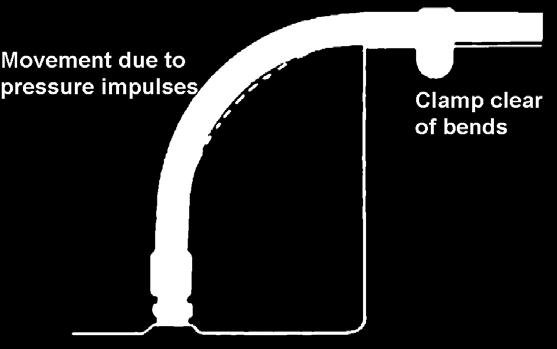
8 Length may vary +2% to -4% when pressure is applied Allow enough slack to accommodate this movement Use the layline to determine that no twist has been induced when tightening. Use 2 spanners to counteract twist Ensure that bending of a hose occurs in the same plane as the movement of the attachment point to avoid induced twist Avoid hot manifolds etc where possible, or isolate with fire sleeve or other protective means Hose movement in 2 planes can induce twist. A clamp at the nodal point will avoid the need for a swivel Using too small a bend radius will greatly reduce hose life, and may cause line collapse and flow restriction TECHNICAL DATA SAE SPECIFICATION Use clamps to support long runs or keep hose away from moving parts. Clamps mustn t be allowed to move (abrasion) Remember that the metal hose fittings are not part of the flexible portion. Allow ample free length for flexing Use elbows and adapters to relieve strain and allow neater installations for easier accessibility and maintenance Avoid sharp corners Have a straight section before bending commences. Use a PIRTEK Hose uard on large multi-spiral hoses to assist Avoid restricting hose movement around bends. Clamping should occur away from the area of movement 7
9 TECHNICAL DATA SAE SPECIFICATION How to measure PIRTEK assemblies Standard Tolerances Assembly length 0mm 12 ins ± 1/8 ins 12 ins 18 ins ± 1/8 ins 18 ins 36 ins ± 1/4 ins 36 ins upwards ±1% Elbow angle ±3 Angular Relationships Hold the assembly so that you can look along the length of the hose and with the fitting furthest away from you in the vertical position. Measure the angle between the vertical fitting and the one nearest to you in a clockwise direction. Relationship can then be expressed from 0 to 360. If the angle is not given, the elbows are positioned at 0. HOSE SIZE TERMINOLOY (HOSE SIZE REFERS TO THE INSIDE DIAMETER) HOSE SIZE DASH SIZE MINE TERMINOLOY METRIC SIZE DN SIZE 1/4-04 NO 4 6 MM DN6 3/8-06 NO 6 10 MM DN10 1/2-08 NO 8 13 MM DN13 5/8-10 NO MM DN16 3/4-12 NO MM DN NO MM DN25 1 1/4-20 NO MM DN32 1 1/2-24 NO MM DN NO MM DN50 2 1/2-40 NO MM DN NO MM DN75 8
10 Flow Rate FLOW V SIZE - PRESSURE LINES SIZE MAX FLOW UK ALS / MIN MAX FLOW US ALS / MIN MAX FLOW LITRES / MIN VELOCITY METRES / SEC 3/ / / / / / / / / FLOW V SIZE - RETURN LINES SIZE MAX FLOW UK ALS / MIN MAX FLOW US ALS / MIN MAX FLOW LITRES / MIN VELOCITY METRES / SEC 3/ / / / / / / / / TECHNICAL DATA SAE SPECIFICATION FLOW V SIZE - SUCTION LINES SIZE MAX FLOW UK ALS / MIN MAX FLOW US ALS / MIN MAX FLOW LITRES / MIN VELOCITY METRES / SEC 3/ / / / / / / / / / / These charts indicate the maximum recommended fluid velocity for the hose sizes in the applications set out. It is always recommended to use a larger size if there is doubt as to the flow, but never a smaller size than indicated. 9
11 TECHNICAL DATA SAE SPECIFICATION U.S. allons per minute Hose Pressure Flow Chart Pressure drop in psi (pounds per square inch) gpm (gallons per minute) / for 10 feet of hose (smooth bore) without fittings. Hose ID (inches) 3/16 1/4 5/16 3/8 13/32 1/2 5/8 3/4 7/ /8 1 1/4 1 3/8 1 1/2 1 13/ Fluid specification: Specific gravity =.85; Viscosity = v = 20 centistokes (C.S.), (20 C.S.= 97 S.S.U.); Ref; MIL-H 5606, 70 F. (+21 C)
12 Formulas and Conversion Factors for Fluid Power Use Quantity Metric Units U.S. Customary Units From Metric to U.S Units From U.S.to Metric Units Area Square centimetres (cm 2 ) Square inches (ins 2 ) cm2 x = ins 2 ins 2 x = cm 2 Length Metres (mt) Feet (ft) mt x ft x = mt Weight Kilograms (Kg) Pounds (lbs) Kg x = lbs lbs x = Kg Volume Power Frequency Load (Torque) Pressure Density Temperature Cubic Centimetres (cm 3 ) Litres (lt) Litres (lt) Kilowatts (KW) Hertz (Hz) Metre Kilograms Kg.m Bar (bar) Kilopascal (KPa) Megapascals (MPa) ram / cubic centimetre (gr / cm 3 ) Degrees Celsius ( O C) Cubic Feet (ft 3 ) U.S. allons (gal) U.K. allons (gal) Horsepower (HP) Cycles / sec (cps) Foot Pounds (ft.lbs) Pounds / square inch (psi) Pounds / square inch (psi) Pounds / square inch (psi) Pounds / cubic inch (lb / ins 3 ) Degrees Fahrenheit ( O F) cm3 x = ft 3 ft 3 x = cm 3 lt x =U.S. gal lt x =U.K. gal HP x = KW Hz = cps Kg.m x = ft.lbs bar x = psi KPa x = psi MPa x 145 = psi U.S. gal x 3.7 = lt U.K. gal x 4.55 = lt KW x = HP cps = Hz ft.lbs x = Kg.m psi x = bar psi x = kpa psi x = MPa gr/cm 3 x = lb/ins 3 lb/ins 3 x = gr/cm 3 (C = F -32) / 1.8 F = (C x 1.8) + 32 TECHNICAL DATA SAE SPECIFICATION 11
13 TECHNICAL DATA SAE SPECIFICATION Inches Conversion to Millimetres Inches Inches Millimetres Fractions Decimals Fractions Decimals Millimetres 1/ / / / / / / / / / / / / / / / / / / / / / / / / / / / / / / / / / / / Inches Fractions Decimals Millimetres 45/ / / / / / / / / / / / / / / / / / / / / / / / / / /
14 Pressure Conversion Factors BAR TO P.S.I. Bar Kilopascals Megapascals Kg / cm 2 PSI , , , , , , , , , , , , , , , , , , , , , P.S.I. TO BAR PSI Kilopascals Megapascals Kg / cm 2 BAR TECHNICAL DATA SAE SPECIFICATION 13
15 TECHNICAL DATA THREAD IDENTIFICATION Thread Identification Thread Identification Page Number Page Number Torque and Threaded Connections 15 Japanese Industrial Standard Metric Male (Komatsu) 25 British Standard Pipe Taper Male 16 Japanese Industrial Standard Metric Female (Komatsu) 25 British Standard Pipe Parallel Male 16 Stapleloc Male 26 British Standard Pipe Parallel Female 17 Stapleloc Female 26 British Standard Pipe Taper Female 17 High Pressure Super Staplelock Male 27 Joint Industry Council Female Swivel 18 High Pressure Super Staplelock Female 27 Joint Industry Council Male 18 SKV 28 Unified National O Ring Male 19 SSKV 29 Society of Automotive Engineers (SAE) Male 19 SAE J518 Code 61 Flange 30 SAE Inverted Flare Female 20 SAE J518 Code 62 Flange 30 SAE Inverted Flare Male 20 Caterpillar Flange 30 National Pipe Taper Fuel Male 21 Komatsu Flange 30 National Pipe Straight Mechanical Female 21 O Ring Face Seal Male 31 DKL Metric Light Male 22 O Ring Face Seal Female 31 DKL Metric Light Female lobe Seal 22 AZ French Metric Male 32 DKS Metric Heavy Male 23 AZ French Metric Female 32 DKS Metric Heavy Female (lobe & O ring Seal) 23 Kobelco Metric Male 33 Japanese Industrial Standard BSPP Male 24 Kobelco Metric Female 33 Japanese Industrial Standard BSPP Female 24 14
 If spiral guard PSAW-25 were fitted over the full length, the designation would be: R1AT-12 / JF1-1212J")

16 Ordering PIRTEK Assemblies Should you wish to describe a PIRTEK hose assembly in an abbreviated form, please use the following format. A forward slash is used to separate each field. Product Codes for fittings can be found in Catalog Section B (except Mining Fittings Section U) If spiral guard PSAW-25 were fitted over the full length, the designation would be: R1AT-12 / JF1-1212J / C J / 48 / PSAW-25 If both ends were fitted with the 45 flanged elbow set in alignment, the designation would appear: Torque and Threaded Connections R1AT-12 / C J / 48 / 0 eneric Pattern : Hose / End A / End B / Length / Protection / Angle BSPT and NPT tapered thread assembly requirements usually dictate a number of wrench flats from hand tight. The hand tight position is described in the British Standard for BSPT as auge Length. Table 1 at right summarises the recommended parameters when tightening these fittings. Note that a thread sealing compound is generally used with both these fittings in order to achieve a seal, and so the use of a torque figure for assembly can play no meaningful role. Thread Identification Tables commencing on page 16 document the recommended tightening torques for JIC and UNO type fittings, since correct torque is essential to minimize leaks from them. Too little torque will preclude proper seat contact, whilst too much can cause O-Ring extrusion (in the case of UNO), splitting of the female JIC seat, damage to the nut, or at the very least damage through cold working of the metal in the contact area. Since thread sealants are not required with these fittings, torque can adopt a more meaningful role in the assembly process. However, in field installation work, suitable torque wrenches are rarely available, and it is usual to fall back to the use of a number of wrench flats from wrench resistance to achieve the desired result. For the case of UNF style fittings, the tabulation at right may assist in achieving the correct torque during assembly if a torque wrench is unavailable during installation. The procedure is: 1. Tighten the nut with the fingers until a distinct bottoming out on the seat can be felt. 2. Use a marking system (permanent marker or centre punch) to provide reference points on the opposing flats of the nut and connector. 3. Tighten the nut with a spanner to rotate it to the tabulated number of hex flats, using the reference marks as a guide. Thread BSPT Tube Size auge Length Turns of Thread Max. Turns of Thread incl. Fitting Allowance Recommended Thread Engagement inches 1/ ½ 7¼ / ¾ 7½ / ½ 7¼ / ¼ ½ 7¼ ¼ ½ 8¼ ½ ½ 8¼ / / Table 1 BSPT Thread Engagement Recommended Thread Engagement lengths for NPT fittings are the same as for BSPT Thread UNF Tube Size Torque Nm No. of Hex Flats from Wrench Resistance 7/ / / /2 3/ /2 7/ /2 1.1/ /4 1.3/ /4 1.5/ / / / Table 2 JIC / UNO Threads Note: Torque values given are for plated steel components without lubrication TECHNICAL DATA THREAD IDENTIFICATION 15
 316 (Stainless Steel) B12361-12362 Part II (Drop Forged) Pipe Size Dash Size Thread BRITISH STANDARD PIPE PARALLEL MALE - (BSPP) Thread Form: AS")

 B12361-12362 Part II (Drop Forged) mm Thread Form: AS 1722.")
 Fixed Adj. mm ins 1/8 2 15 1/8-28 8702 5076 9.73 0.383 1/4 4 37 1/4-19 8702 5801 13.16 0.518 3/8 6 59 3/8-19 8702 5801 16.67 0.656 1/2 8 74 1/2-14 5801 5076 20.96 0.")
17 TECHNICAL DATA THREAD IDENTIFICATION Thread Identification BRITISH STANDARD PIPE TAPER MALE - (BSPT) Thread Form: AS , ISO 7 Materials Available: S12L14 (Mild Steel) 316 (Stainless Steel) B Part II (Drop Forged) Pipe Size Dash Size Thread BRITISH STANDARD PIPE PARALLEL MALE - (BSPP) Thread Form: AS , ISO 228 Seal: DIN 3852 Part 11 Form E Materials Available: S12L14 (Mild Steel) 316 Stainless Steel B Part II (Drop Forged) Max Work Press (psi) Thread OD D on Diagram 1/8 2 1/ , /4 4 1/ /8 6 3/ /2 8 1/ /8 * 10 5/ /4 12 3/ / / / / Thread Form: AS , ISO 228 Seal: DIN 3852 Part 2 Form B Materials Available: S12L14 (Mild Steel) B Part II (Drop Forged) mm Thread Form: AS , ISO 228 Seal: ISO Form Materials Available: S12L14 (Mild Steel) B Part II (Drop Forged) in Pipe Size Dash Size Correct Torque Thread Max Work Press (psi) Thread OD D on Diagram (ft/lbf) Fixed Adj. mm ins 1/ / / / / / / / /8 * / / / / / / / * 5/8 Size is not subject to Standards Note: The torque values given are for plated carbon steel components without lubrication. 16
18 Thread Identification BRITISH STANDARD PIPE PARALLEL FEMALE - (BSPP) Thread Form: AS , ISO 228 Materials Available: S12L14 (Mild Steel) B Part II (Drop Forged) 316 Stainless Steel Pipe Size Dash Size Thread Form: AS , ISO 228 Sealing area: DIN 3852 Part 2 Form X Correct Torque (ft/lbf) Thread TAPER FEMALE - (BSPT) Thread Form: AS , ISO 228 Materials Available: S12L14 (Mild Steel) B Part II (Drop Forged) 316 Stainless Steel Max Work Press (psi) Thread ID D on Diagram Fixed Swivel mm ins 1/ / / / / / / / /8 * / / / / / / / TECHNICAL DATA THREAD IDENTIFICATION * 5/8 Size is not subject to Standards Note: The torque values given are for plated carbon steel components without lubrication. 17
 Dash Size Tube Size in Correct Torque ft/lbf Thread Max Working Pressure (psi) Thread OD D on Diagram 02 1/8 6-7 5/16-24 - 7.87.310 03 3/16 8-9 3/8-24 - 9.65.")


19 TECHNICAL DATA THREAD IDENTIFICATION 18 Thread Identification JOINT INDUSTRY COUNCIL - (JIC) - MALE Thread Form: SAE J514 Materials Available: S12L14 (Mild Steel) 316 (Stainless Steel) B Part II (Drop Forged) Dash Size Tube Size in Correct Torque ft/lbf Thread Max Working Pressure (psi) Thread OD D on Diagram 02 1/ / / / / / / / / / / / / / / / / / / / / / / / Note: The hex flats from finger tight method is recommended for 37 and 45 flare fittings. The torque values given are for plated carbon steel components without lubrication. See page 15 JOINT INDUSTRY COUNCIL - (JIC) - FEMALE Thread Form: SAE J514 Materials Available: S12L14 (Mild Steel) 316 (Stainless Steel) B Part II (Drop Forged) Dash Size Tube Size in Correct Torque ft/lbf Thread Max Working Pressure (psi) mm in Thread ID D on Diagram mm in 02 1/ / / / / / / / / / / / / / / / / / / / / / / / Note: The hex flats from finger tight method is recommended for 37 and 45 flare fittings. The torque values given are for plated carbon steel components without lubrication. See page 15 JOINT INDUSTRY COUNCIL- (JIC) - PIRTEK TEST PRESSURES (HOSE TAILS) IMPORTANT SAFETY NOTE: While PIRTEK s thread termination pressure ratings exceed those stipulated in the respective Standards, discretion must be used prior to selection for appropriate applications. These test pressures correlate to material S12L14 Dash Size Tube Size in Correct Torque ft/lbf Thread Actual Max Work Pressure (psi) Min. Burst Press (psi) No. of Wrench Flats from Wrench Resistance 02 1/ /16-24 N/A N/A 03 3/ /8-24 N/A N/A 04 1/ / *c / / *c / / *c /2 08 1/ / *c /2 10 5/ / *c /2 12 3/ / *c /4 14 7/ / *c / / *w / / *w / / *w / *w *c = Crimped Nut *w = Wire Nut Note: The hex flats from finger tight method is recommended for 37 and 45 flare fittings. The torque values given are for plated carbon steel components without lubrication. See page 15
20 Thread Identification UNIFIED NATIONAL O RIN - (UN-O) Pipe Size Thread Form: SAE J1926, ISO Materials Available: S12L14 (Mild Steel) Dash Size Correct Torque (ft/lbf) Thread Thread Form: SAE J1926, ISO Materials Available: S12L14 (Mild Steel) Adjustable type Max Working Pressure (psi) Thread OD D on Diagram Fixed Adj. mm ins 2 1/ / / / / / / / / / / / / / / / / / / / / / Note: The hex flats from finger tight method is recommended for UN-O fittings. The torque values given are for plated carbon steel components without lubrication. See page 15 TECHNICAL DATA THREAD IDENTIFICATION SOCIETY OF AUTOMOTIVE ENINEERS - (SAE) - MALE 45 Thread Form: SAE J512 Materials Available: S12L14 (Mild Steel) 352 DR Brass Alloy B Part II (Drop Forged) Dash Thread Maximum Working Pressure (psi) Thread OD D on Diagram Size Tube Size in Steel Brass mm in 2 1/8 5/ /16 3/ /4 7/ /16 1/ S 3/8 5/ /2 3/ /8 7/ /4 1.1/ / / / Note: The hex flats from finger tight method is recommended for 37 and 45 flare fittings. The torque values given are for plated carbon steel components without lubrication. See page 15 19
 Thread SOCIETY OF AUTOMOTIVE ENINEERS - (SAE) - INVERTED FLARE MALE Thread Form: SAE J512 Materials Available: S12L14 (Mild Steel) 352 DR Brass Alloy Max Work Pressure (psi) Thread ID D on")


21 TECHNICAL DATA THREAD IDENTIFICATION Thread Identification SOCIETY OF AUTOMOTIVE ENINEERS - (SAE) - INVERTED FLARE FEMALE Thread Form: SAE J512 Materials Available: 352 DR Brass Alloy Dash Size Tube Size (ins) Thread SOCIETY OF AUTOMOTIVE ENINEERS - (SAE) - INVERTED FLARE MALE Thread Form: SAE J512 Materials Available: S12L14 (Mild Steel) 352 DR Brass Alloy Max Work Pressure (psi) Thread ID D on Diagram Steel Brass mm in 2 1/8 5/ /16 3/ /4 7/ /16 1/ /8 5/ /16 11/ /2 3/ /8 7/ /4 1.1/ Thread Form: SAE J512 Materials Available: S12L14 (Mild Steel) 352 DR Brass Alloy Adapter Version Tube version Pipe Size Dash Size Thread Max Work Press (psi) - SAE J1065 Thread OD D on Diagram Fixed Adj. mm ins 2 1/8 5/ /16 3/ /4 7/ /16 1/ /8 5/ /16 11/ /2 3/ /8 7/ /4 1. 1/
22 Thread Identification NATIONAL PIPE TAPER FUEL- (NPTF) Thread Form: SAE J476 Materials Available: S12L14 (Mild Steel) 316 (Stainless Steel) B Part II (Drop Forged) NATIONAL PIPE STRAIHT MECHANICAL - (NPSM) Thread Form: SAE J476 Materials Available: S12L14 (Mild Steel) 316 (Stainless Steel) B Part II (Drop Forged) Pipe Size Dash Size Thread Max Work Press (psi) Thread OD D on Diagram 1/8 2 1/ /4 4 1/ /8 6 3/ /2 8 1/ /4 12 3/ / / / / / / / / Pipe Size Dash Size Thread Max Work Press (psi) mm in Thread OD D on Diagram 1/8 2 1/ /4 4 1/ /8 6 3/ /2 8 1/ /4 12 3/ / / / / / / / / mm in TECHNICAL DATA THREAD IDENTIFICATION 21
23 TECHNICAL DATA THREAD IDENTIFICATION Thread Identification METRIC MALE DKL LIHT SERIES Dash Size METRIC FEMALE DKL LIHT SERIES Tube Size D2 mm Correct Torque ft/lbf Thread Max Work Press (psi) DIN2401 Pt 1 Thread OD D1 on Diagram M M M M M M Thread Form: DIN 2353, DIN 3861, DIN M , DIN 3902 Materials Available: S12L14 (Mild Steel) M (Stainless Steel) B Part II M (Drop Forged) M Note: The torque values given are for plated carbon steel components without lubrication. Thread Form: DIN 2353 DIN 3861 DIN 3901 DIN 3902 Materials Available: S12L14 (Mild Steel) 316 (Stainless Steel) B Part II (Drop Forged) Dash Size Tube Size D2 mm Correct Torque Nm Thread Max Work Press (psi) DIN2401 Pt 1 Thread ID D1 on Diagram M M M M M M M M M M Note: The torque values given are for plated carbon steel components without lubrication. 22
24 Thread Identification METRIC MALE DKS HEAVY SERIES Dash Size METRIC FEMALE DKS HEAVY SERIES Tube Size D2 mm Correct Torque ft/lbf Thread Max Work Press (psi) DIN2401 Pt 1 Thread OD D1 on Diagram M M M M M M Thread Form: DIN 2353, DIN 3861, DIN 3901, DIN M Materials Available: S12L14 (Mild Steel) M (Stainless Steel) B Part II M (Drop Forged) M Note: The torque values given are for plated carbon steel components without lubrication. Thread Form: DIN 2353 DIN 3861 DIN 3901 DIN 3902 Materials Available: S12L14 (Mild Steel) 316 (Stainless Steel) B Part II (Drop Forged) Thread Form: DIN 2353 DIN 3861 DIN 3901 DIN 3902 Materials Available: S12L14 (Mild Steel) 316 (Stainless Steel) B Part II (Drop Forged) TECHNICAL DATA THREAD IDENTIFICATION Dash Size Tube Size D2 mm Correct Torque lb/lbf Thread Max Work Press (psi) DIN2401 Pt 1 Thread ID D1 on Diagram (mm) M M M M M M M M M M Note: The torque values given are for plated carbon steel components without lubrication. 23
25 TECHNICAL DATA THREAD IDENTIFICATION Thread Identification JAPANESE INDUSTRIAL STANDARD MALE - BSPP Thread Form: JIS B8363 Materials Available: S12L14 (Mild Steel) B Part II (Drop Forged) JAPANESE INDUSTRIAL STANDARD FEMALE - BSPP Thread Form: JIS B8363 Materials Available: S12L14 (Mild Steel) B Part II (Drop Forged) Dash Thread Max Work Press Thread ID D on Diagram Tube Size Thread Size (psi) ins mm mm in 2 1/ / / / /8 10 3/ /2 12 1/ /4 19 3/ / / / / Dash Thread Max Work Press Thread ID D on Diagram Tube Size Thread Size (psi) ins mm mm in 2 1/ / / / /8 10 3/ /2 12 1/ /4 19 3/ / / / /
26 Thread Identification JAPANESE INDUSTRIAL STANDARD KOMATSU MALE - METRIC Thread Form: JIS B8363 Materials Available: S12L14 (Mild Steel) B Part II (Drop Forged) Dash Thread Max Work Press Thread ID D on Diagram Tube Size Thread Size (psi) ins mm mm in / / / / JAPANESE INDUSTRIAL STANDARD KOMATSU FEMALE - METRIC Thread Form: JIS B8363 Materials Available: S12L14 (Mild Steel) B Part II (Drop Forged) Dash Thread Max Work Press Thread ID D on Diagram Tube Size Thread Size (psi) ins mm mm in / / / / TECHNICAL DATA THREAD IDENTIFICATION 25
27 TECHNICAL DATA THREAD IDENTIFICATION Thread Identification STAPLELOK Staplelok has its origins in the erman coal mining industry. It is often referred to as Stecko, the name given to the product by its inventor, and derived from the erman verb stecken meaning to pin, along with a truncation of O-Ring. Staplelok has become the predominant hydraulic hose fitting world wide in underground coal mining. Sealing and Identification: The male spigot is equipped with an annular O-Ring with Teflon backup ring that together seal against the cylindrical machined wall of the female coupling. Retention is via a horseshoe shaped square section staple that is inserted through holes in the female socket. The holes align with an annular slot in the male fitting. Advantages: Allows connections to be made in confined spaces and in difficult environments. No torsional load is applied in the fitting, and connection is easy, with no need of spanners. A combination hammer and lever tool is commonly used to facilitate insertion and removal of staples. Variations: Available in the original form, and a more recent Super form to cope with demands for higher working pressures. The Super form employs the same design characteristics, but uses an extra wide staple (sometimes in the form of 2 standard staples laminated together) to increase the shear strength of the staple. No published Standard exists for the Super form. STAPLELOK MALE & FEMALE Size Nom. Tube Size W or Hole Dia mm D on Diagram mm Max. Working Pressure (psi) (Based on Use of in mm Male Fem Male Female St. Steel D Staples) 6 1/4" /8" /2" /4" " /4" Thread Form: DIN SAE J1467 PIRTEK adapters meet or exceed DIN20043, BS6537, and NCB638 requirements Materials Available: See below /2" " /2" Materials Used in PIRTEK Standard Staplelok Adapters: from ¼ to 2 material conforms to BS M07/C45 2-1/2 material 50 D (BS ) (UNI EN S355J23 extruded tube) Stainless Steel staples of all types conform to 420S45 (1.4028) (X30Cr13) in BS EN :

 in mm Male Fem Male Female (Based on Use of St. Steel D Staples) 13 1/2\" 8 9.1 9.1 15.")

28 Thread Identification STAPLELOK SAFETY The life expectancy of staples subjected to high pressures and impulses is potentially less than that of the hose and fittings combinations within the same circuit Failure of a staple can result in fracture of the staple, or a loss of spring tension leading to dislodgement as a result of system depressurization followed by re-pressurisation FOR THIS REASON, PIRTEK RECOMMENDS THAT STAPLES SHOULD ALWAYS BE REPLACED BY NEW STAPLES WHEN UNDERTAKIN EQUIPMENT MAINTENANCE OR OVERHAULS SUPER STAPLELOK MALE & FEMALE * Not covered by Standard Thread Form: Materials Available: See below Size Nom. Tube Size W or Hole Dia mm D on Diagram mm Max. Working Pressure (psi) in mm Male Fem Male Female (Based on Use of St. Steel D Staples) 13 1/2" /4" " /4" /2" " TECHNICAL DATA THREAD IDENTIFICATION * Not covered by Standard Materials Used in PIRTEK Super Staplelok Adapters: from ¾ to 2 body material conforms to 212 A42 Stainless Steel staples of all types material is 420S45 (1.4028) (X30Cr13) in BS EN :
29 TECHNICAL DATA THREAD IDENTIFICATION Thread Identification SKV / SSKV SSKV and its lower pressure derivative SKV, like Staplelok, have their origins in ermany. Developed specifically for applications requiring secure connections without the need for special tools, and without the drawbacks associated with the older Staplelok technology (bulky profile and easily dislodged or broken staples), it finds many applications both in mining and general industry. The acronym SSKV is derived from the erman language meaning steckschalenklemmverbindung or plug shell clamp connection. Sealing and Identification: Sealing resembles Staplelok in that the male spigot is equipped with an annular O-Ring with Teflon backup ring. These seal against the cylindrical machined wall of the female coupling. Retention is however much more sophisticated than Staplelok. A spring loaded shell not unlike a Victaulic clamp is retained by means of a threaded nut that is hand tightened into position to prevent dislodgement of the shell. An (optional) removeable red coloured clip behind the threaded nut in turn prevents unplanned loosening of the nut. Size identification is by way of the male hand nut and collar OD or female body OD and bore measurements. Advantages: Allows connections to be made in confined spaces and in difficult environments. No torsional load is applied in the fitting, and connection is easy, with no need of spanners. The slim external profile of the coupling does not protrude beyond the hose outside diameter in most cases, and overall connection length is short. There exist no projecting components to cause snagging or dislodgement. The 2 forms of the fittings are dimensionally different to preclude accidental intermixing between different pressure circuits. Variations: Available in both medium and high pressure forms to fill the demands for a wide range of working pressures. The SSKV form has been extensively tested within Australia to SAE J343 for both working pressure and impulse cycles, and has comfortably exceeded 500,000 impulses in all tests (continuing). No Standard exists for either form of the fitting at this point. Both forms of the fitting are suited to applications where MD41 compliance is demanded. SKV MALE & FEMALE Retaining Nut ø D3 ø D1 Seal Set ø D2 Size Nom. Tube Size D1 or Hole Dia mm D2 on Diagram D3 on Diagram mm mm Max. Pressure (psi) ins mm Male Female Male Female Male Female WP Burst 06 1/ / / ø D 1 Materials Available: See below ø D / / / / Materials Used in PIRTEK SKV Adapters: from ¼ to 2 material conforms to BS M07/C45 28


30 Thread Identification SKV / SSKV ASSEMBLY PROCEDURE Step 1: Ensure you have the appropriate SKV / SSKV components The SKV / SSKV connections comprise: Support Clip Shell Male End w/- Retaining Nut Female End SSKV MALE & FEMALE * Seal Set Size Step 2: Lubricate the O-Ring and internal body of the female fitting using PIRTEK Protect Lanoline rease. Insert the male spigot into the female until the shoulders touch as can be seen in the photograph at right. Step 3: Fit the spring supported Shell over the mating male and female connection and ensure that it is a snug fit into the grooves, equally ensuring that the two halves of the shell meet and align. Ensure that the split in the Shell is level, parallel and forms a complete closed diameter to ensure that it is properly engaged in the grooves as evident at right. Step 4: Lubricate the thread of the retaining nut with PIRTEK Protect Lanoline rease. Turn the retaining nut toward the shell by hand until it meets firmly against the shoulder of the shell. A C Spanner may be used, but is not essential. Clip the optional plastic safety clip into position firmly at the rear of the retaining nut ensuring that it is not loose, although some sideways movement is permitted in the housing groove. Nom. Tube Size D1 or Hole Dia mm D2 on Diagram D3 on Diagram mm mm Max. Pressure (psi) ins mm Male Female Male Female Male Female W.P. Burst 06 1/ TECHNICAL DATA THREAD IDENTIFICATION ø D1 ø D2 10 3/ Retaining Nut ø D3 13 1/ ø D 1 Materials Available: See below ø D / / / * 2 1/ Materials Used in PIRTEK SSKV Adapters: from 3/8 to 2.1/2 body material conforms to 212 A42 29
FITTING IDENTIFICATION AMERICANT THREAD TYPES APPENDIX ALFAGOMMA // APPENDIX. Dash numers. NPTF (National Pipe Tapered Fuel)
") // FITTINGS GUIDelines FITTING IDENTIFICATION numers Most fluid piping system sizes are measured by dash numbers. These are universally used abbreviations for the size of component expressed as the numerator
// FITTINGS GUIDelines FITTING IDENTIFICATION numers Most fluid piping system sizes are measured by dash numbers. These are universally used abbreviations for the size of component expressed as the numerator
TECHNICAL DATA PRODUCT ENQUIRY
 Centre Contact Person Customer / End User Date PRODUCT ENQUIRY / DEVELOPMENT FORM Page 1 of 2 Please send this completed form to: group.tech@pirtek.com.au OR Fax to (02) 8822 9019 SIZE Millimetres TEMPERTURE
// ADapters GUIDelines
 // ADapters GUIDelines ADAPTER SELECTION Selection of an appropriate ALFAGOMMA adapter for a given application depends on the fluid system operating parameters listed below and the tube material and wall
Guide for Evaluating Your Hose Assembly Supplier
 Guide for Evaluating Your Hose Assembly Supplier Supplier Evaluation Checklist, and How to Clearly Define Application Requirements Safe, reliable hose assemblies require appropriate specification work
ISO/TC 131/SC Hydraulic fluid power Test methods for hoses and hose assemblies
 DRAFT INTERNATIONAL STANDARD ISO/DIS 6605 ISO/TC 131/SC 4 Secretariat: ANSI Voting begins on: Voting terminates on: 2016-02-03 2016-05-03 Hydraulic fluid power Test methods for hoses and hose assemblies
Torque Specifications
 SENR3130-10 Torque Specifications All Caterpillar Products S/N From the library of Barrington Diesel Club CONTENT General Information 01/07/2005 Introduction to Torque 01/07/2005 Torque-Turn 01/07/2005
A hose layline contains important information for specifying the replacement assembly: manufacturer, hose trade name, working pressure and hose ID.
 CONTENTS Introduction Pressure Pressure Drop Temperature Rating Bend Radius Conclusion Additional Information SIDEBAR: Understanding Hydraulic Hose Reinforcement INTRODUCTION Hydraulic hose has a finite
Pipe threads for tubes and fittings where pressure-tight joints are not made on the threads. (requires PTFE sealing tape or liquid sealant).
.") Fittings for CO 2 Pipe Threads Pipe thread references quoted in this catalogue conform with the requirements specified in the latest issue and amendments of the following ISO Standards: ISO 7-1 (BS21)
Fittings for CO 2 Pipe Threads Pipe thread references quoted in this catalogue conform with the requirements specified in the latest issue and amendments of the following ISO Standards: ISO 7-1 (BS21)
Flexible Metal Hose Products
 Flexible Metal Hose Products Specialty Flexible Hose Solutions of Stainless Steel The AEROCOM Advantage Aerocom offers engineered solutions that address specific flexible piping challenges such as vibration,
THERMOPLASTIC HOSE INSTALLATION FACTORS
 INSTALLATION FACTORS THERMOPLASTIC HOSE INSTALLATION FACTORS The specifications and particular conditions of use also determine the limits for the correct use of Transfer Oil products. Accordingly, Transfer
(1) Type (2) Thread size (T) (3) Wrench size specification : inch spec. (NPT, UNF) : mm spec. (M, R)
 Type (2) Thread size (T) (3) Wrench size specification : inch spec. (NPT, UNF) : mm spec. (M, R)") This exhaust needle valve, which comes with silencer, controls the exhaust flow rate. The valve can be attached directly to a solenoid valve where a cylinder or like mechanism has no sufficient space around
This exhaust needle valve, which comes with silencer, controls the exhaust flow rate. The valve can be attached directly to a solenoid valve where a cylinder or like mechanism has no sufficient space around
(1) Name of tube (2) Tube dia. (O.D./I.D.) (3) Tube length. (4) Tube color. Model UD0425. UD1290 O.D. I.D. (mm) UD1075 UD0860 UD
 Name of tube (2) Tube dia. (O.D./I.D.) (3) Tube length. (4) Tube color. Model UD0425. UD1290 O.D. I.D. (mm) UD1075 UD0860 UD") The polyurethane tube, featuring excellent flexiblity, helps compact piping requiring small bending radius. The useful cut marks at 500mm interval are printed on the tube. Model UD0425 UD0640 UD0860 UD1075
The polyurethane tube, featuring excellent flexiblity, helps compact piping requiring small bending radius. The useful cut marks at 500mm interval are printed on the tube. Model UD0425 UD0640 UD0860 UD1075
Rapidmain Installation Guide
 Rapidmain Installation Guide Aluminium Compressed Air Pipe Work Installation Guide Trafalgar Court, Waterloo Ind Estate, Widnes Cheshire. UK. Ref: Rapidmain installation guide 4b Index 1. Rapidmain fittings:
ptfe and stainless steel hoses
 ptfe and stainless steel hoses 3 table of contents Description P.004 Description of FX01 hoses P.004 Description of FX02 hoses P.004 Description of FX03 hoses P.005 Description of FX06 hoses P.005 DESCRIPTION
COMPRESSION TUBE FITTINGS
 COMPRESSION TUBE FITTINGS 1/16 THROUGH 2 2 MM THROUGH 50 MM LET-LOK TUBE FITTINGS DESCRIPTION The HAM-LET GROUP has produced high quality tube and pipe fittings in various materials for high pressure applications
Cautions : 1. The gauge orientation on the GPU and GPM types can be changed by using
 The compact-size pressure gauge can be installed in small spaces. With the built-in tube fitting type, tube connection is the only necessary step before pressure indication. Fluid medium Indicated pressure
Quick reference. Quick reference
 Quick reference Quick reference Measurement methodology for frequently occurring hose fittings Hose size ight series Heavy series Fine thread Banjo French (pipe in inches) French ( pipe light) French (
COMPRESSION TUBE FITTINGS
 COMPRESSION TUBE FITTINGS 1/16 THROUGH 2 2 MM THROUGH 50 MM LET-LOK TUBE FITTINGS DESCRIPTION The HAM-LET GROUP has produced high quality tube and pipe LET-LOK HOW DOES IT WORK? A HAM-LET has gained an
INTERLOCKED METAL HOSE
 INTERLOCKED METAL HOSE HOSE FUNDAMENTALS Penflex interlocked metal hoses are made for a variety of specialized industrial applications and are available in a wide range of metals, styles and sizes. Interlocked
Engineering Data Sheet
 Page 1 of 6 CE MARKING AND THE PRESSURE EQUIPMENT DIRECTIVE 97/23/EC Valves must be installed into a well designed system and it is recommended that the system be inspected in accordance with the appropriate
ISO 3996 INTERNATIONAL STANDARD. Road vehicles - Brake hose assemblies for hydraulic braking Systems used with non-petroleum-base brake fluid
 Provläsningsexemplar / Preview INTERNATIONAL STANDARD ISO 3996 Third edition 1995-02-01 Road vehicles - Brake hose assemblies for hydraulic braking Systems used with non-petroleum-base brake fluid Vkhicules
Coiling Tube with Twist-Proof Fitting
 http://www.pisco.co.jp FITTING CONTROLLER VALVE TUBE MAKE-TO-ORDER PRODUCTS Push-In Fitting Type Anti-Twisting Coiling Tube for Air Tool Coiling Tube with Twist-Proof Fitting 306 Avoid Twisted Tube Problem
World Area Differences Technical Information
 World Area Differences Technical Information DMISC2047X02 This document is to give more information about the following: Porting & Threads Cleaning Procedures Conversion Tables PORTING & THREADS NPT (National
INSTALLATION, OPERATION AND MAINTENANCE GUIDE
 INSTALLATION, OPERATION AND Placement in Pipeline System When installing Process Development & Control s ElastoTITE Elastomer-Hinged Check Valves in a pipeline, a minimum of five pipe diameters should
Flexible hoses - Non-metallic materials
 CLASS PROGRAMME Type approval DNVGL-CP-0183 Edition December 2015 The electronic pdf version of this document, available free of charge from http://www.dnvgl.com, is the officially binding version. FOREWORD
PLEASE NOTE: Pressures for 200mm (8ins) and 250mm (10ins) are based on the use of METALFLEX Braided Braid
 and 250mm (10ins) are based on the use of METALFLEX Braided Braid") METCONAB B-FLEX Stainless Steel Annular Convoluted Hose. A close pitch hose with a high degree of flexibility suitable for most applications and normally supplied. BRAID Single or double layers of Stainless
METCONAB B-FLEX Stainless Steel Annular Convoluted Hose. A close pitch hose with a high degree of flexibility suitable for most applications and normally supplied. BRAID Single or double layers of Stainless
Hose Manufacturing Data
 Hydraulic & Offshore Supplies Hose Manufacturing Data YOUR GATEWAY TO GLOBAL SUPPLY HOSE ASSEMBLIES PRESSURE TESTING WALFORM EQUIPMENT PACKAGES FLANGES PIPE & TUBE HOSE MANUFACTURING DATA STORAGE Detailed
Spilt body Flange ball valve. TC-205MFF-PN1640 User Manual English Version. Document No: TC-205MFF-PN1640.Ur-manual. Date: 2007/04/2617. Version: 1.
 Spilt body Flange ball valve TC-205MFF-PN1640 Series PED Category I,II TC-205MFF-PN1640 User Manual English Version Use for company in Europe who will place the product on the market, please amend which
Cautions : 1. Clogging of the element raises resistance to exhaust, thus lowering the
 The Silencer, connected to the exhaust port of a device, suppresses the exhaust noise. The Silencer displays an excellent noise suppression effect. Three types are available for your selection. The element
SECTION BUTTERFLY VALVES
 SECTION 15112 BUTTERFLY VALVES PART 1 GENERAL 1.01 SUMMARY A. All butterfly valves shall be of the tight closing, rubber seated type and fully comply with the latest revision of AWWA Standard C504, Class
SAFETY MANUAL FOR FLAMMABLE PRODUCT TRANSFER
 SAFETY MANUAL FOR FLAMMABLE PRODUCT TRANSFER SUPPLIMENT TO eom IMPORTANT READ THIS MANUAL BEFORE PRODUCT INSTALLATION, OPERATION, INSPECTION & MAINTENANCE Tougher and more rigid guidelines are being established
IAPMO GUIDE CRITERIA FOR BALL VALVES IAPMO IGC PURPOSE
 INTERNATIONAL ASSOCIATION OF PLUMBING AND MECHANICAL OFFICIALS IAPMO GUIDE CRITERIA FOR BALL VALVES IAPMO IGC 157-20067 1 PURPOSE 1.1 The purpose of this standard is to establish an acceptable standard
ISO INTERNATIONAL STANDARD. Hydraulic fluid power Hose assemblies Part 1: Dimensions and requirements
 INTERNATIONAL STANDARD ISO 17165-1 First edition 2007-10-15 Hydraulic fluid power Hose assemblies Part 1: Dimensions and requirements Transmissions hydrauliques Flexibles de raccordement Partie 1: Dimensions
FITTINGS THREAD LUBRICANTS. Fittings 20,000 PSI
 Jetstream offers a wide variety of fittings with various connection types to fit your 20,000 psi application needs. The standard connection types, Type M, MP, and MP Tube lance, are available in standard
Cautions : 1. Be careful when you release the Stop Fitting with some internal pressure
 The flow-shut mechanism will operate to stop the air flow when the tube is disconnected and will allow air flow when the tube is connected. The double-passage structure facilitates easy connection and
RS(H)10,15 USER MANUAL. Read the complete manual before installing and using the regulator.
10,15 USER MANUAL. Read the complete manual before installing and using the regulator.") RS(H)10,15 USER MANUAL Read the complete manual before installing and using the regulator. WARNING INCORRECT OR IMPROPER USE OF THIS PRODUCT CAN CAUSE SERIOUS PERSONAL INJURY AND PROPERTY DAMAGE. Due to
RS(H)10,15 USER MANUAL Read the complete manual before installing and using the regulator. WARNING INCORRECT OR IMPROPER USE OF THIS PRODUCT CAN CAUSE SERIOUS PERSONAL INJURY AND PROPERTY DAMAGE. Due to
P-04 Stainless Steel Corrugated Hoses and Metal Bellows Expansion Joints
 Guideline No.P-04 (201510) P-04 Stainless Steel Corrugated Hoses and Metal Bellows Expansion Joints Issued date: 20 th October 2015 China Classification Society Foreword This Guideline is a part of CCS
User Information Sheet 024
 User Information Sheet 024 November 2010 PREPARATION, INSTALLATION, INSPECTION, TESTING AND MAINTENANCE OF RUBBER HOSES, UP TO AND INCLUDING 76 mm INTERNAL DIAMETER IN ACCORDANCE WITH BS EN 1762. 1 Introduction.
Gas Lines. Technical Manual. Sumitomo (SHI) Cryogenics of America, Inc Vultee Street Allentown, PA U.S.A.
 Cryogenics of America, Inc Vultee Street Allentown, PA U.S.A.") Gas Lines Technical Manual Sumitomo (SHI) Cryogenics of America, Inc. 1833 Vultee Street Allentown, PA 18103-4783 U.S.A. Revision F: April 2008 261320A TABLE OF CONTENTS Page DESCRIPTION...1 SPECIFICATIONS...2
Gas Lines Technical Manual Sumitomo (SHI) Cryogenics of America, Inc. 1833 Vultee Street Allentown, PA 18103-4783 U.S.A. Revision F: April 2008 261320A TABLE OF CONTENTS Page DESCRIPTION...1 SPECIFICATIONS...2
V48 Series 3-Way Pressure-Actuated Water-Regulating Valves With Union Fittings
 Installation Instructions V48 Issue Date 08/30/01 V48 Series 3-Way Pressure-Actuated Water-Regulating Valves With Union Fittings Application IMPORTANT: The V48 Series 3-Way Pressure-Actuated Water-Regulating
Gas Welding Hoses and connections, the weak link
 Gas Welding Hoses and connections, the weak link By Leif Andersen, Technical Product Manager Welding, WSS Regulators with flashback arrestors and the shank with its welding or cutting attachment are made
Installation Instructions and valve Maintenance Rev. 0 of 21/09/15
 ASSEMBLING PROCEDURE AND VALVE MAINTENANCE 1.0.... Safety Information 2.0.. INTRODUCTION 3.0 VARIATIONS 4.0..ASSEMBLING PROCEDURE FOR THE STEM 5.0 ASSEMBLING PROCEDURE FOR OUTLET CONNECTIONS 6.0 PROCEDURE
FLAMMABLE GASES AND FLAMMABLE CRYOGENIC FLUIDS
 CHAPTER 35 FLAMMABLE GASES AND FLAMMABLE CRYOGENIC FLUIDS SECTION 3501 GENERAL 3501.1 Scope. The storage and use of flammable gases shall be in accordance with this chapter. Compressed gases shall also
Model MC Circuit Setter Hose Kits Supply Valve Options: Ball Valve, UBY
 Model MC Circuit Setter Hose Kits Supply Valve Options: Ball Valve, UBY Model MC Circuit Setter Description: Circuit Setter Balance Valves are precision engineered valves which function as precise system
Rubber Dock Hose care, Use & Maintenance
 Rubber Dock Hose care, Use & Maintenance Prepared by: Thomas J. Wise VP Corporate Development Contents Revised - July. 2014 1. Novaflex Rubber Dock Hose Testing & Inspection Program 1.1 Introduction -
Installation Instructions and valve Maintenance Rev. 0 of 29/09/15
 Pag1 ASSEMBLING PROCEDURE AND VALVE MAINTENANCE 1.0.... Safety Information 2.0.. INTRODUCTION 3.0 VARIATIONS 4.0..ASSEMBLING PROCEDURE FOR THE STEM 5.0 ASSEMBLING PROCEDURE FOR OUTLET CONNECTIONS 6.0 PROCEDURE
TECHNICAL DATA. Page 1 of 12
 Page 1 of 12 1. DESCRIPTION The Viking Regulating Valve is a direct-acting, single-seated, spring-loaded diaphragm valve. When installed as a pilot regulating valve on a Viking Model H or J Flow Control
WHY PREVENTIVE MAINTENANCE?
 CONTENTS Why preventive maintenance?... 5 Avoid fluid injection injuries... 6 Choosing the right components... 7 Choosing the right hose... 8 Choosing the right coupling... 11 Periodic inspections... 16
Dual Solenoid Gas Valve Installation
 Installation IMPORTANT: These instructions are intended as a guide for qualified personnel installing or servicing FLYNN Gas Products. Carefully follow all instructions in this bulletin and all instructions
Technical Standard Order
 Department of Transportation Federal Aviation Administration Aircraft Certification Service Washington, DC TSO-C75 Date: 9/4/63 Technical Standard Order Subject: TSO-C75, HYDRAULIC HOSE ASSEMBLIES Technical
HOSE & FLEXIBLE TUBING
 http://southwest.swagelok.com HOSE & FLEXIBLE TUBING PROVIDED BY SWAGELOK SOUTHWEST SWAGELOK SOUTHWEST Swagelok Hose and Flexible Tubing Metal Hose & Tubing FX Series Metal Hose FM Series Metal Hose FJ
Gas powered stop valves, type GPLX REFRIGERATION AND AIR CONDITIONING. Technical leaflet
 Gas powered stop valves, type GPLX 80-150 REFRIGERATION AND AIR CONDITIONING Technical leaflet Technical leaflet Gas powered stop valves, type GPLX 80-150 Contents Page Introduction........................................................................................3
(1) Type. (2) Tube dia. (ød) : ø8mm (ø5/16in.) (3) Thread size (T) (4) Specification. Fluid medium. Air, water * 1, * 2, * 3 Max. operating pressure
 Type. (2) Tube dia. (ød) : ø8mm (ø5/16in.) (3) Thread size (T) (4) Specification. Fluid medium. Air, water * 1, * 2, * 3 Max. operating pressure") This type of tube fitting comes in eight lengths to suit your applications. The tube fitting, provided with a hexagonal hole, can be easily installed using an Allen wrench, even in a narrow or limited
This type of tube fitting comes in eight lengths to suit your applications. The tube fitting, provided with a hexagonal hole, can be easily installed using an Allen wrench, even in a narrow or limited
Data Sheet. Hose Crimp, Fittings and Crimping Equipment. System 48 series hose end fittings A B
 Data Pack G Issued 11/ 05 1502984506 Data Sheet Hose Crimp, Fittings and Crimping Equipment A range of high quality hose crimp fittings and crimping equipment. Manufacturers one piece fittings, which eliminate
SWAGELOK HOSES HOSE & FLEXIBLE TUBING SWAGELOK BANGALORE CHENNAI DELHI HYDERABAD
 SWAGELOK HOSES HOSE & FLEXIBLE TUBING SWAGELOK BANGALORE CHENNAI DELHI HYDERABAD Swagelok Hose and Flexible Tubing Metal Hose & Tubing FX Series Metal Hose FM Series Metal Hose FJ Series Metal Hose FL
Flange Bolt Torquing. for Resistoflex Plastic-Lined Piping Products. Torquing. Retorquing. Hydrotesting. Annual retorquing
 Flange Bolt Torquing for Resistoflex Plastic-Lined Piping Products Torquing When assembling flange connections, always use a full complement of clean, new high strength A193-B7 bolting. If using stainless
3-PIECE BALL VALVE, 3600 PSI/ PN 248, WITH ISO DIRECT MOUNTING PAD 306M SERIES/ PED Category II
 3-PIECE BALL VALVE, 3600 PSI/ PN 248, WITH ISO DIRECT MOUNTING PAD 306M SERIES/ PED Category II 306M User Manual English Version Use for company in Europe who will place the product on the market, please
Installation Operating Instructions for Simple Duplex Manual Manifolds PX-TSD Series
 Introduction Powerex manifolds are cleaned, tested and prepared for the indicated gas service and are built in accordance with the Compressed Gas Association guidelines. The manifold consists of a regulator
Type /2-Way Globe Valve 3/2-Wege-Geradsitzventil Vanne à siège droit 3/2 voies Operating Instructions Bedienungsanleitung Manuel d utilisation
 3/2-Way Globe Valve 3/2-Wege-Geradsitzventil Vanne à siège droit 3/2 voies Operating Instructions Bedienungsanleitung Manuel d utilisation We reserve the right to make technical changes without notice.
V46 Series 2-Way Pressure-Actuated Water-Regulating Valves With Union Fittings
 Installation Instructions V46 Issue Date 11//1 V46 Series -Way Pressure-Actuated Water-Regulating Valves With Union Fittings Application IMPORTANT: The V46 Series -Way Pressure-Actuated Water-Regulating
H4802, H4802-1, H , and Pole Tampers
 SERVICE MANUAL H4802, H4802-1, H-4802-6, and 43227 Pole Tampers Serial Codes FKA, FKF, FKM, FZP, FZR, FZT, and FZV Read and understand all of the instructions and safety information in this manual before
Vickers. Flow Controls. Flow Controls FN, F(C)G, FRG. Released 6/94
G, FRG. Released 6/94") Vickers Flow Controls Flow Controls FN, F(C)G, FRG Released 6/94 685 Table of Contents FN03/06/10 Model Series Application Data...............................................................................
Vickers Flow Controls Flow Controls FN, F(C)G, FRG Released 6/94 685 Table of Contents FN03/06/10 Model Series Application Data...............................................................................
Technical Data Sheet. R&M Closures
 R&M Closures About this data sheet Edition 3.0 This document has been drafted with utmost care and reflects the products July, 2013 engineering level at the time of publication. Amendments or corrections
Application Data Important Safety Information
 Important Safety Information Read this page before using any of the information in this catalog. This catalog is designed to be used as a guide in selecting the proper hose for the applications listed
POP Safety Valve. POP Safety Valve INTRODUCTION DEFINITIONS
 POP Safety Valve POP Safety Valve INTRODUCTION The effects of exceeding safe pressure levels in an unprotected pressure vessel or system, can have catastrophic effects on both plant and personnel. Safety
Two Ferrule Tube Fittings 316 stainless steel ranging from 1/8" to 1" (6mm to 25mm) O.D.
 O.D.") Two errule Tube ittings 316 stainless steel ranging from 1/8" to 1" (6mm to 25mm) valve & fitting www.veelok.com Introduction Vee-Lok tube fittings are designed to provide a leak-free connection and applied
Two errule Tube ittings 316 stainless steel ranging from 1/8" to 1" (6mm to 25mm) valve & fitting www.veelok.com Introduction Vee-Lok tube fittings are designed to provide a leak-free connection and applied
TRADITIONAL HIGH VIBRATION HOSE SYSTEM THE STANDARD FOR MANY AUTOMOTIVE APPLICATIONS
 O-Ring Face Seal Hose TRADITIONAL HIGH VIBRATION HOSE SYSTEM THE STANDARD FOR MANY AUTOMOTIVE APPLICATIONS O-Ring Face Seal METAL FORMING SOLUTIONS THE STANDARD FOR MANY AUTOMOTIVE APPLICATIONS Table of
TROUBLESHOOTING Hydraulics
 2. Protect hose. Nylon and urethane sleeving and spring guards can be used to protect the cover from abrasion. See page 62 for more information. 3. Change to a hose with a cover that is compatible with
PTF4 Pivotrol Pump (patented) version Dual Mechanism - Pressure Powered Pump
 version Dual Mechanism - Pressure Powered Pump") Local regulations may restrict the use of this product to below the conditions quoted. In the interests of development and improvement of the product, we reserve the right to change the specification without
Local regulations may restrict the use of this product to below the conditions quoted. In the interests of development and improvement of the product, we reserve the right to change the specification without
(1) Type (2) Cylinder dia. (3) Gripper action : Single-acting closing gripper (normally open) (4) Holder type
 Type (2) Cylinder dia. (3) Gripper action : Single-acting closing gripper (normally open) (4) Holder type") These are air finger models featuring light weight and miniature size. Blank fingers are available for the K type fingers as option. R-guide leaves no possibility of misalignment. The blank finger can
These are air finger models featuring light weight and miniature size. Blank fingers are available for the K type fingers as option. R-guide leaves no possibility of misalignment. The blank finger can
SIMPLAIR PIPING TOOL. JXT Company
 SIMPLAIR PIPING INGERSOLL-RAND SIMPLAIR PIPING With push-in fittings and lightweight anodized aluminum pipe, a SimplAir system provides ideal connection throughout your entire air distribution system.
Selecting the Proper Hose Assembly. M MATERIAL type of material conveyed, including composition and concentration
 Assemblies 322 Selecting the Proper Hose Assembly In order to obtain the best service from any particular hose application, two important conditions must be fulfilled. 1) Select the right hose for the
COMPRESSION TUBE FITTINGS 1/16 THROUGH 2 -INCH, 2 MM THROUGH 50 MM-METRIC
 1/16 THROUGH 2 -INCH, 2 MM THROUGH 50 MM-METRIC LET-LOK TUBE FITTINGS DESCRIPTION HAM-LET LET-LOK HOW DOES IT WORK? HAM-LET LET-LOK LET-LOK LET-LOK HAM-LET LET-LOK 1 4 3 2 4 Tube 1 2 3 1 2 3 4 6 LET-LOK
INSTALLATION & MAINTENANCE INSTRUCTION
 ARCHON Industries, Inc Liquid Level Gauges Models: BT-LLG ND-LLG INSTALLATION & MAINTENANCE INSTRUCTION Instruction No.: 1014.2 Revision Issued: 3/01/03 Approved: Engineering Manager Warning ONLY QUALIFIED
Pressure Relief Valve DHV 718
 Advantages frictionless components low maintenance low pressure increase up to fully opened valve constant low vibration controlling hermetically sealed by diaphragm for oscillating pumps for viscous media
V146 Series 2-Way Pressure-Actuated Water-Regulating Valves
 roduct/technical Bulletin V146 Issue Date November 20, 2002 V146 Series 2-Way ressure-actuated Water-Regulating s The V146 Series 2-Way ressure-actuated Water-Regulating s regulate water flow and control
shutoff valves 900 Series psig Manual Shutoff Valves
 0 6000 psig Manual Shutoff Valves Features Zero leakage Protected o-ring Full flow passages Freedom from wire drawing Panel mount standard Hand wheel or toggle handle How it Works Closed O-ring seal on
Materials : Dichromate zinc plated steel flanges or AISI 316
 Size : Ends : Min Temperature : Max Temperature : DN 25 to 300 Flanges PN10/16-35 C + 90 C Max Pressure : 16 Bars (10 bars at 90 C) Specifications : Absorb vibrations and noise Linear and angular compansion
BUTTERFLY VALVES. Toll Free (877) - ICFLUID -2-
 - ICFLUID -2-") BUTTERFLY VALVES 1. General HyrdoWer is a globally recognized manufacturer of power unit accessories. They have become specialists in the design of Butterfly Valves and Hydraulic Compensators. The shut
BUTTERFLY VALVES 1. General HyrdoWer is a globally recognized manufacturer of power unit accessories. They have become specialists in the design of Butterfly Valves and Hydraulic Compensators. The shut
CLASS D - SENSITIVE LEAK TEST GAS AND BUBBLE METHOD. 1.1 To provide definitive requirements for PNEUMATIC pressure testing of piping systems.
 Page 1 of 7 CLASS D - SENSITIVE LEAK TEST GAS AND BUBBLE METHOD 1. SCOPE 1.1 To provide definitive requirements for PNEUMATIC pressure testing of piping systems. 1.2 The piping system as used herein is
TECHNICAL DATA. Pressure Regulation 531a. April 24, 2009
 April 24, 29 Pressure Regulation 531a 1. DESCRIPTION The Viking Regulating Valve is a direct-acting, single-seated, spring-loaded diaphragm valve. When installed as a pilot regulating valve on a Viking
TECHNICAL DATA. Q = C v P S
 Preaction 346a 1. Description The 6 Model G-6000P Electric Release Preaction System Riser Assembly can be used as a Single Interlock Preaction System with Electric Release, or as a Double Interlock Preaction
HYDRALECTRIC LIMITED,
 Description:... 2 Applications:... 2 General Performance Data:... 2 Pressure Drop:... 3 General Construction Data:... 4 Dimensioning:... 4 Hose Data:... 5 Insulation:... 5 Ferrule Data:... 5 Installation:...
Pressure Gauge Series
 Pressure Gauge Series Compact Design. Connection type In line Plug in Panel mount Threaded Model Designation (Example) GP C 15 U10 U 1 Type Pressure Gauge 1 Type 2 Series 4 Wrench size 3 Thread size/ Tube
3/8" Dr. Air Butterfly Impact Wrench
 8192106 3/8" Dr. Air Butterfly Impact Wrench Owner s Manual Read and understand all instructions before use. Retain this manual for future reference. Specifications Construction: Polished aluminum and
TECHNICAL DATA. Q = C v P S
 Page 1 of 13 1. DESCRIPTION The Viking 6 Model G-6000 Dry Valve Riser Assembly consists of a small profile, light weight, pilot operated valve that is used to separate the water supply from the dry sprinkler
Preparation and Installation of the Sanitary BDI-FLX Sensor and Connection to the BDI-FLX Interface Cable
 GEP-6075 Rev. B 101574 Ref. I.D.: 16973 Preparation and Installation of the Sanitary BDI-FLX Sensor and Connection to the BDI-FLX Interface Cable WARNING USER SHOULD READ AND THOROUGHLY UNDERSTAND THESE
Push-In Fitting Type with Stop Valve
 http://www.pisco.co.jp Push-In Fitting Type with Stop Valve 278 Push-In Fitting Type with Stop Valve for General Pneumatic Piping. Air Stop by Tube Disconnection. Easy Insertion and Disconnection by Double-passage
General Performance Data Hose Ref Minimum Bend. Safety Pressure at 20 C (BAR) Working Pressure at. Flow Rate at 3 bar (lit/min) Working Pressure
 Working Pressure at. Flow Rate at 3 bar (lit/min) Working Pressure") The Classic range provides a safe and taint free conveyance of potable water supplies for Domestic and Commercial plumbing applications. The range is designed to achieve robust and flexible solutions with
The Classic range provides a safe and taint free conveyance of potable water supplies for Domestic and Commercial plumbing applications. The range is designed to achieve robust and flexible solutions with
EASTERN ENERGY SERVICES PTE LTD. 60 Kaki Bukit Place #02-19 Eunos Tech Park Singapore, SG Singapore Telephone: Fax:
 2 Table Of Contents 1. Introduction 3 2. About this Manual 3 3. Contacting YZ Systems 3 4. Vessel Components 4 5. Specifications 5 6. Application 6 7. Theory of Operation 7 8. DuraSite Installation & Use
Storage Systems and Accessories
 Storage Systems and Accessories High Pressure Air and Inert Gases 4500-6000 PSIG DOT and ASME Cylinders High Pressure Storage Systems If an application requires storage, either in the form of a single
Translation of the original Operating Instructions for HKS rubber compensators
 Because of their flexible elements and mechanisms, HKS rubber compensators are susceptible to damage of all types and adverse loads in operation. For reliable operation of a compensator and, thus, the
Push-In Fitting Type Pressure Gauge
 http://www.pisco.co.jp CONTROLLER VALVE TUBE MAKE-TO-ORDER PRODUCTS Push-In Fitting Type 526 Compact Design. Pressure Indication by Tube Insertion into Push-In Fitting. Check Valve Silencer Controller
ACCESSORY KIT INSTALLATION INSTRUCTIONS
 ACCESSORY KIT INSTALLATION INSTRUCTIONS 1NP0680 - PROPANE CONVERSION FOR USE WITH MODELS: PM8, PC8, PM9, PC9, FL9M, FL9C, FC9M, FC9C This conversion kit is to be installed by a qualified service agency
SKP Series SKP25 U.. Pressure Regulating Gas Valve Actuator with Safety Shut-off Function
 SKP Series SKP25 U.. Pressure Regulating Gas Valve Actuator with Safety Shut-off Function Technical Instructions Document No. 155-752 SKP25 U.. Description Only when assembled to Series VG Gas valves SKP25
Fluid Sealing Association
 Fluid Sealing Association STANDARD FSA-PSJ-701-06 PIPING SYSTEMS NON-METALLIC EXPANSION JOINT HYDROTESTING AND VACUUM TESTING 994 Old Eagle School Road, Suite 1019 Wayne, Pennsylvania 19087-1866 Phone:
TECHNICAL DATA 3 MODEL G-3000 DRY VALVE RISER ASSEMBLY
 Page 1 of 13 1. DESCRIPTION The Viking 3 Model G-3000 Dry Valve Riser Assembly is equipped with a small profile, light weight, pilot operated valve that is used to separate the water supply from the dry
GM Series Dual-Block Multi-Function Gas Control Valves
 Installation Sheets Manual 121 Gas Combustion Combination Controls and Systems Section G Technical Bulletin GM Issue Date 0297 GM Series Dual-Block Multi-Function Gas Control Valves Figure 1: GM Series
Tube for Clean Environment Polyurethane Tube Clean-Room Package
 http://www.pisco.co.jp TUBE MAKE-TO-ORDER PRODUCTS for Clean Environment Polyurethane Clean-Room Package 642 Fine Flexibility. Suitable for Small Bending Radius in General Pneumatic Piping. Cleaned and
Hydraulic Maintenance. Hydraulic. Maintenance & Safety. Safety
 Hydraulic Hydraulic Maintenance Maintenance & Safety Safety Tips to prevent downtime and save you money. Presented by Gates India Table of Contents Why Preventive Maintenance? Why Preventive ydraulic preventive