TRYCLOPS. X Purge Controller XP Version. User s Manual
|
|
|
- Randolf Williamson
- 5 years ago
- Views:
Transcription


1 TRYCLOPS X Purge Controller XP Version User s Manual
2 This page intentionally left blank
 and the rights of the trademark(s) owned by the company referred to herein.")
3 Information in this document is subject to change without notice. All terms mentioned in this manual that are known to be trademarks have been appropriately capitalized. Purge Solutions, Inc. acknowledges all trademark(s) and the rights of the trademark(s) owned by the company referred to herein. 592 Avenue E 1/2, Alvin, Texas USA Phone: Fax: info@purgesolutions.com Web site: Release Date: 25-November-2003 Document Number: DO M Copyright 2003 by Purge Solutions, Inc. All rights reserved Revision Record Rev. Description Date A Initial Release 25-Nov-03 B Several Revisions 29-June-04 C Several Revisions 27-May-05 D Added Recommended Grounding Method 16-Jun-05 E Added Recommended UL Power Supply Requirements 06-Jan-06 F Updated Options and Illustrations 11-May-06 G Updated Options and Illustrations 14-Jan-07 H Revisions Per Certification Updates 27-Sep-08 I Several Required Revisions 09-Jun-11 J Addition of Increase Safety Window Kits 12-Aug-12 K Company Address Change 11-Dec-13 L Certification Required Revisions 01-Oct-14 M Added Storage Temperature Range 21-May-15 N Change of Address 01-Jun-16
4 Copyright Notice This document contains information proprietary to Purge Solutions, Inc. with all rights reserved worldwide. Any reproduction or disclosure of this publication, or any part thereof, to persons other than Purge Solutions, Inc. personnel or customers is strictly prohibited, except by written permission of Purge Solutions, Inc. Unauthorized use, disclosure, reproduction, or translation of this publication will result in Purge Solutions, Inc. exercising maximum possible legal action against all persons and / or organizations involved. Disclaimer Purge Solutions, Inc. makes no representations or warranties with respect to the contents hereof. Further, Purge Solutions, Inc. reserves the right to revise this publication and to make changes in the content hereof, without obligation to notify any person or organization of such revision or changes. Shipment Arrival Procedures This shipment has been thoroughly inspected at the factory prior to its delivery to the carrier. After the shipment is picked up by the carrier, it becomes their responsibility. When the shipment arrives, make certain that it is undamaged and complete. Patent Notice Manufactured under United States, Worldwide Patents, and Patents Pending. Trademark Information Purge Solutions, Inc. and its logo(s) are trademark(s) of Purge Solutions, Inc.
5 Table of Contents i Table of Contents Legal Notices and Revision History Inside Front Cover Section 1 How To Use This Manual 1 Safety Considerations 1 Label Definition Table 2 Locating Information 2 General Safety 3 General Precautions 3 Electrical Power 4 System Location 4 Purge Systems 4 Section 2 Specifications 5 Features Table 5 Normal Operating Conditions Table 5 Utility Requirements Table 6 Environmental Conditions Table 6 Model Number Matrix Tables 7 Section 3 Introduction 19 Description 19 Warranty 22 Section 4 Installation 23 Mounting 23 Electrical Power Installation 28 Power Source Specifications Table 28 Power Connection to Purge Controller Table 29 Power Connection to Equipment Table 29 Power Connection from Purge Controller to Solenoid Valve 30 Alarm Source Specifications Table 31 Alarm Connections Table 31 Normal Operation Mode Alarm Matrix 32 By-Pass Mode Switch Alarm Matrix 32 Section 5 Start Up Procedures 33 Normal Operation Mode Initial Startup Procedure 33 Power Disconnect By-Pass Switch Mode Initial Startup Procedure 45 Normal Operation Mode Maintenance or Service Startup Procedure 61 Power Disconnect By-Pass Switch Mode Maintenance or Service Startup Procedure 67 Section 6 Documents 73 Flow Diagram 76 Exhaust Vents 80 Dimensional General Assemblies 89 Wiring Diagrams 92 Section 7 Options 94 Section 8 Getting Help 98
6
7 1 Section 1 How to Use This Manual Safety Considerations: This chapter includes important information that must be read and understood by all persons installing, using, or maintaining this equipment. While this manual is designed to aid personnel in the correct and safe installation, operation, and maintenance of the systems described. Personnel must consider all actions and procedures for potential hazards or conditions that may not have been anticipated in the written procedures. If a procedure cannot be performed safely, it must not be performed until appropriate actions can be taken to ensure the safety of equipment and personnel. The procedures in this manual are not designed to replace or supersede required or common sense safety practices. All safety warnings listed in any documents applicable to equipment and parts used in or with the system described in this manual must be read and heeded before commencing work on any part of the system. NOTE: Refer to all ATEX, CSA, IECEx, NEC, NFPA and UL certificates for any Special Conditions of Use. If the sign X is placed after the certificate number, it indicates that the equipment or protective system is subject to special conditions for safe use specified in the schedule of the certificate. NOTE: Review all material and safety information in this manual and install in accordance with this document and all other applicable ATEX, CSA, IECEx, NEC, NFPA 496 and UL standards. WARNING: Failure to follow appropriate safety procedures or inappropriate use of the equipment described in this manual can lead to injury of personnel or equipment damage. WARNING EXPLOSION HAZARD Do not disconnect equipment unless power has been removed or the area is known to be non-hazardous.
8 2 The following symbols are used throughout this manual to alert users to potential hazards or important information. Failure to heed the warnings and cautions listed herein can lead to injury and equipment damage. Document Label Definitions Used To Indicate Potential Hazards Symbol Label Description WARNING: CAUTION: Consists of conditions, practices, or procedures that must be observed to prevent injury and / or equipment damage. Risk of electric shock or high temperature parts may result in injury if proper precautions are not taken. NOTE: Emphasizes important or essential information. Locating Information: NOTE: In the interest of completeness, manuals and drawings included with the system may provide information pertaining to options not included with your equipment. Information in application notes supersedes general information in these documents. Information can be located in this manual using any of the following aids. 1. Table of Contents 2. Getting Help
9 3 General Safety and Operating Information: This section contains general safety and operating information applicable to electrical equipment installed within hazardous locations. This information must be understood by all persons installing, using, or maintaining the electrical equipment. This information is designed to aid personnel in safe installation, operation, and maintenance of the TRYCLOPS X Purge Controller, XP Version. It is not designed to replace or limit appropriate safety measures applicable to work performed by personnel. Any additional safety and operating measures that are required must be determined by and followed by personnel performing work on the electrical equipment. WARNING: Deviation from the specified instruction or procedure steps can result in equipment malfunction, equipment damage, or injury to personnel. WARNING: Return unit to factory for any repairs or replacement of parts, customer not permitted. This will void all warranties and hazardous area certification(s). General Precautions: Protective eyewear (glasses with side shields or goggles as appropriate) must be worn when servicing any part of electrical equipment. Hot components should be allowed to cool before servicing if possible. Other appropriate equipment or clothing must be used as required by the type of work performed. All applicable regulations and procedures must be followed for the work performed. Before beginning any work on the equipment, carefully consider all the potential hazards and ensure that appropriate measures are taken to prevent injury to personnel or equipment damage. CAUTION: Electrical equipment components may be hot even when power is not applied. Take appropriate precautions to prevent injury from contact with hot items. CAUTION: Applicable permits must be obtained and appropriate precautions must be taken to prevent possible injury to personnel or equipment damage when installing or maintaining this equipment.
10 4 Electrical Power: The TRYCLOPS X Purge Controller, XP Version uses AC power of 115 or 230 volts. The AC power is converted to DC. Appropriate precautions must be taken to prevent sparks that may ignite combustible materials that may be present in the purge controller s environment. Precautions must also be taken to prevent electrical shock if the electrical equipment s enclosure being monitored by purge controller is opened. The power to the TRYCLOPS X Purge Controller, XP Version must be free from noise, surges, sags, and spikes for proper operation of the purge controller. AC power circuit breakers and wiring must be sized properly for the required current. All wiring installations must meet applicable area electrical codes. System Location: TRYCLOPS X Purge Controller, XP Version must be installed in a suitable location. The TRYCLOPS X Purge Controller, XP Version must not be installed in an area classification for which it is not rated and must be protected from temperature extremes. The TRYCLOPS X Purge Controller, XP Version should not be mounted in an area with potentially high vibration. The TRYCLOPS X Purge Controller, XP Version must be attached securely and appropriately in the general area of the electrical equipment s enclosure(s) being monitored per the mounting instructions page 23. The TRYCLOPS X Purge Controller, XP Version must be mounted in a location to permit adequate viewing of indicator lights and proper purge exhaust venting. Purge Systems: Electrical equipment may use purging to ensure safe operation when installed within a hazardous location. The protective gas purge supply must be clean, dry, and free from hydrocarbons or corrosive materials. All protective gas purge supply pressures must be set correctly and all electrical equipment enclosure doors must be closed securely. Purged enclosure(s) must not be opened unless power is removed from the electrical equipment or the area is known to be non-hazardous. CAUTION: Electrical equipment enclosure(s) being monitored by TRYCLOPS X Purge Controller, XP Version must not be opened unless power is removed from the electrical equipment or the area is known not to contain explosive materials.
11 5 Section 2 Specifications Features and Certifications Certified for installation and use in ATEX, IECEx and CE Type X Purge, II 2 G Ex e mb ib [px] IIC T4 Gb For Zone 1 gas hazardous areas Type X - Purge, II 2 D Ex tb IIIC T119 C Db IP66 For Zone 1 dust hazardous areas ATEX Certification Number = DNV 09 ATEX 48607X IECEx Certification Number = IECEx DNV X Standards = IEC / EN , IEC / EN , IEC / EN , IEC / EN , IEC / EN and IEC / EN Certified for installation and use in CEC, NEC / NFPA and UL Type X Purge, Class I, Division 1, Group B, C & D, T4 For Division 1 gas hazardous areas Type X Purge, Class II, Division 1, Group E, F & G, T4 For Division 1 dust hazardous areas Monitors purge pressure(s), exhaust flow(s), and controls electrical power to one, two, or three pressurized enclosure(s) Programmable pre-purge dilution time 1 to 99 minutes Normal Operating Conditions Power Automatically applied to the electrical equipment within the enclosure(s) being monitored by purge controller. Automatic Time Dilution Purge Delay To Energizing Electrical Equipment TRYCLOPS X Purge Controller, XP Version, Minimum Pressure Typically, dilution purge time delay is to ensure that at least five (5) times the volume of free space in the largest enclosure of protective gas supply is exchanged before power is applied to the electrical equipment. Ten (10) times volume for motors, generators and other rotating electrical machinery. Green indicator light remains on to show purge pressure being maintained is above 0.50 inch H2O (1.25 mbar) Standard, 0.30 inch H2O (0.75 mbar) Optional, in enclosure(s) being monitored.
12 6 WARNING: The number of exchanged volumes may be higher in some situations. Purge Protective Gas Supply Pressure to Pressure Regulator Purge Protective Gas Supply Quality Power Control Capability Power Input / Consumption Voltage Utility Requirements 20 psig (1.4 Bar) minimum (Suggested, to compensate for enclosure leak rate) Water and oil-free, - 40 F (- 40 C) dew point, particles 5µ, ISA grade hydrocarbon-free 115VAC, 50/60 Hz, switches up to 25 Amps RSM 230VAC, 50/60 Hz, switches up to 12.5 Amps RSM 2 Watts maximum 115VAC model (85VAC to 160VAC) 47 to 63 Hz 230VAC model (130VAC to 265VAC) 47 to 63 Hz Mains Supply Fluctuation Not to Exceed 10% Over Voltage Category II IEC Environmental Conditions Operating Temperature Range - 40 F to 150 F (- 40 C to 65 C) Storage Temperature Range - 58 F to 167 F (- 50 C to 75 C) Used and Mounted For Indoor and Outdoor Use Enclosure Material Specifications Anodized Aluminum, Weight lbs. (13.48 kg) 316 Stainless Steel, Weight lbs. (31.78 kg) Anodized Aluminum Protection NEMA 4, (IP66) 316 Stainless Steel NEMA 4X, (IP66) NOTE: Purge Solutions, Inc. is NOT responsible for any misuse or improper installation of product, assumes no liability for special or consequential damages caused by use or misuse or improper installation of its products sold and assumes no liability for injury from use or misuse or improper installation of its products or attached products.
13 7 TRYCLOPS X Purge Controller, XP Version, 0.50 inch H2O (1.25 mbar) Pressure Switch, Up to 15 Cubic Foot (425 liters) Enclosure Volume, Model Number Matrix Enclosures Being Monitored Voltage Material Model Number 1 115VAC Anodized Aluminum PST-11A VAC Anodized Aluminum PST-21A VAC Anodized Aluminum PST-31A VAC Anodized Aluminum PST-12A VAC Anodized Aluminum PST-22A VAC Anodized Aluminum PST-32A VAC Stainless Steel PST-11S VAC Stainless Steel PST-21S VAC Stainless Steel PST-31S VAC Stainless Steel PST-12S VAC Stainless Steel PST-22S VAC Stainless Steel PST-32S1
14 8 TRYCLOPS X Purge Controller, XP Version, 0.30 inch H2O (0.75 mbar) Pressure Switch, Up to 15 Cubic Foot (425 liters) Enclosure Volume, Model Number Matrix Enclosures Being Monitored Voltage Material Model Number 1 115VAC Anodized Aluminum PST-11A VAC Anodized Aluminum PST-21A VAC Anodized Aluminum PST-31A VAC Anodized Aluminum PST-12A VAC Anodized Aluminum PST-22A VAC Anodized Aluminum PST-32A VAC Stainless Steel PST-11S VAC Stainless Steel PST-21S VAC Stainless Steel PST-31S VAC Stainless Steel PST-12S VAC Stainless Steel PST-22S VAC Stainless Steel PST-32S1.3
15 9 TRYCLOPS X Purge Controller, XP Version, X Alarm, 0.50 inch H2O (1.25 mbar) Pressure Switch, Up to 15 Cubic Foot (425 liters) Enclosure Volume, Model Number Matrix Enclosures Being Monitored Voltage Material Model Number 1 115VAC Anodized Aluminum PST-11A1X 2 115VAC Anodized Aluminum PST-21A1 X 3 115VAC Anodized Aluminum PST-31A1X 1 230VAC Anodized Aluminum PST-12A1X 2 230VAC Anodized Aluminum PST-22A1X 3 230VAC Anodized Aluminum PST-32A1X 1 115VAC Stainless Steel PST-11S1X 2 115VAC Stainless Steel PST-21S1X 3 115VAC Stainless Steel PST-31S1X 1 230VAC Stainless Steel PST-12S1X 2 230VAC Stainless Steel PST-22S1X 3 230VAC Stainless Steel PST-32S1X
16 10 TRYCLOPS X Purge Controller, XP Version, X Alarm, 0.30 inch H2O (0.75 mbar) Pressure Switch, Up to 15 Cubic Foot (425 liters) Enclosure Volume, Model Number Matrix Enclosures Being Monitored Voltage Material Model Number 1 115VAC Anodized Aluminum PST-11A1X VAC Anodized Aluminum PST-21A1X VAC Anodized Aluminum PST-31A1X VAC Anodized Aluminum PST-12A1X VAC Anodized Aluminum PST-22A1X VAC Anodized Aluminum PST-32A1X VAC Stainless Steel PST-11S1X VAC Stainless Steel PST-21S1X VAC Stainless Steel PST-31S1X VAC Stainless Steel PST-12S1X VAC Stainless Steel PST-22S1X VAC Stainless Steel PST-32S1X.3
17 11 TRYCLOPS X Purge Controller, XP Version, 0.50 inch H2O (1.25 mbar) Pressure Switch, Up to 75 Cubic Foot (2,125 liters) Enclosure Volume, Model Number Matrix Enclosures Being Monitored Voltage Material Model Number 1 115VAC Anodized Aluminum PST-11A VAC Anodized Aluminum PST-21A VAC Anodized Aluminum PST-31A VAC Anodized Aluminum PST-12A VAC Anodized Aluminum PST-22A VAC Anodized Aluminum PST-32A VAC Stainless Steel PST-11S VAC Stainless Steel PST-21S VAC Stainless Steel PST-31S VAC Stainless Steel PST-12S VAC Stainless Steel PST-22S VAC Stainless Steel PST-32S2
18 12 TRYCLOPS X Purge Controller, XP Version, 0.30 inch H2O (0.75 mbar) Pressure Switch, Up to 75 Cubic Foot (2,125 liters) Enclosure Volume, Model Number Matrix Enclosures Being Monitored Voltage Material Model Number 1 115VAC Anodized Aluminum PST-11A VAC Anodized Aluminum PST-21A VAC Anodized Aluminum PST-31A VAC Anodized Aluminum PST-12A VAC Anodized Aluminum PST-22A VAC Anodized Aluminum PST-32A VAC Stainless Steel PST-11S VAC Stainless Steel PST-21S VAC Stainless Steel PST-31S VAC Stainless Steel PST-12S VAC Stainless Steel PST-22S VAC Stainless Steel PST-32S2.3
19 13 TRYCLOPS X Purge Controller, XP Version, X Alarm, 0.50 inch H2O (1.25 mbar) Pressure Switch, Up to 75 Cubic Foot (2,125 liters) Enclosure Volume, Model Number Matrix Enclosures Being Monitored Voltage Material Model Number 1 115VAC Anodized Aluminum PST-11A2X 2 115VAC Anodized Aluminum PST-21A2X 3 115VAC Anodized Aluminum PST-31A2X 1 230VAC Anodized Aluminum PST-12A2X 2 230VAC Anodized Aluminum PST-22A2X 3 230VAC Anodized Aluminum PST-32A2X 1 115VAC Stainless Steel PST-11S2X 2 115VAC Stainless Steel PST-21S2X 3 115VAC Stainless Steel PST-31S2X 1 230VAC Stainless Steel PST-12S2X 2 230VAC Stainless Steel PST-22S2X 3 230VAC Stainless Steel PST-32S2X
20 14 TRYCLOPS X Purge Controller, XP Version, X Alarm, 0.30 inch H2O (0.75 mbar) Pressure Switch, Up to 75 Cubic Foot (2,125 liters) Enclosure Volume, Model Number Matrix Enclosures Being Monitored Voltage Material Model Number 1 115VAC Anodized Aluminum PST-11A2X VAC Anodized Aluminum PST-21A2X VAC Anodized Aluminum PST-31A2X VAC Anodized Aluminum PST-12A2X VAC Anodized Aluminum PST-22A2X VAC Anodized Aluminum PST-32A2X VAC Stainless Steel PST-11S2X VAC Stainless Steel PST-21S2X VAC Stainless Steel PST-31S2X VAC Stainless Steel PST-12S2X VAC Stainless Steel PST-22S2X VAC Stainless Steel PST-32S2X.3
21 15 TRYCLOPS X Purge Controller, XP Version, 0.50 inch H2O (1.25 mbar), Up to 200 Cubic Foot (5,663 liters) Enclosure Volume, Model Number Matrix Enclosures Being Monitored Voltage Material Model Number 1 115VAC Anodized Aluminum PST-11A VAC Anodized Aluminum PST-21A VAC Anodized Aluminum PST-31A VAC Anodized Aluminum PST-12A VAC Anodized Aluminum PST-22A VAC Anodized Aluminum PST-32A VAC Stainless Steel PST-11S VAC Stainless Steel PST-21S VAC Stainless Steel PST-31S VAC Stainless Steel PST-12S VAC Stainless Steel PST-22S VAC Stainless Steel PST-32S3
22 16 TRYCLOPS X Purge Controller, XP Version, 0.30 inch H2O (0.75 mbar), Up to 200 Cubic Foot (5,663 liters) Enclosure Volume, Model Number Matrix Enclosures Being Monitored Voltage Material Model Number 1 115VAC Anodized Aluminum PST-11A VAC Anodized Aluminum PST-21A VAC Anodized Aluminum PST-31A VAC Anodized Aluminum PST-12A VAC Anodized Aluminum PST-22A VAC Anodized Aluminum PST-32A VAC Stainless Steel PST-11S VAC Stainless Steel PST-21S VAC Stainless Steel PST-31S VAC Stainless Steel PST-12S VAC Stainless Steel PST-22S VAC Stainless Steel PST-32S3.3
23 17 TRYCLOPS X Purge Controller, XP Version, X Alarm, 0.50 inch H2O (1.25 mbar), Up to 200 Cubic Foot (5,663 liters) Enclosure Volume, Model Number Matrix Enclosures Being Monitored Voltage Material Model Number 1 115VAC Anodized Aluminum PST-11A3X 2 115VAC Anodized Aluminum PST-21A3X 3 115VAC Anodized Aluminum PST-31A3X 1 230VAC Anodized Aluminum PST-12A3X 2 230VAC Anodized Aluminum PST-22A3X 3 230VAC Anodized Aluminum PST-32A3X 1 115VAC Stainless Steel PST-11S3X 2 115VAC Stainless Steel PST-21S3X 3 115VAC Stainless Steel PST-31S3X 1 230VAC Stainless Steel PST-12S3X 2 230VAC Stainless Steel PST-22S3X 3 230VAC Stainless Steel PST-32S3X
24 18 TRYCLOPS X Purge Controller, XP Version, X Alarm, 0.30 inch H2O (0.75 mbar), Up to 200 Cubic Foot (5,663 liters) Enclosure Volume, Model Number Matrix Enclosures Being Monitored Voltage Material Model Number 1 115VAC Anodized Aluminum PST-11A3X VAC Anodized Aluminum PST-21A3X VAC Anodized Aluminum PST-31A3X VAC Anodized Aluminum PST-12A3X VAC Anodized Aluminum PST-22A3X VAC Anodized Aluminum PST-32A3X VAC Stainless Steel PST-11S3X VAC Stainless Steel PST-21S3X VAC Stainless Steel PST-31S3X VAC Stainless Steel PST-12S3X VAC Stainless Steel PST-22S3X VAC Stainless Steel PST-32S3X.3
25 19 Section 3 Introduction Description: Type X purging reduces the classification within a protected electronics enclosure from Division 1 / Zone 1 to non-hazardous. The TRYCLOPS X Purge Controller, XP Version is used to provide safe control and monitoring of electrical equipment in Division 1 and Zone 1 hazardous areas. To prevent the possibility of fire or explosion inside the enclosure(s) of energized electrical equipment, a protective gas supply is used to dilute potentially flammable materials to an acceptable level, creating a safe area for the electrical equipment within the enclosure(s). Positive pressure prevents the ingress of flammable materials in the surrounding atmosphere from entering into the enclosure(s), as long as positive pressure is maintained. After the electronics enclosure(s) is purged, power may be automatically applied to the protected electrical equipment. The TRYCLOPS X Purge Controller, XP Version provides an objective evidence of the presence of adequate positive purge pressure within the electrical equipment enclosure(s) and the enclosures exhaust port(s) flow of up to three separate enclosure(s). When the monitored electronics enclosure(s) registers a pressure of at least 0.50 inches H2O (1.25 mbar) above the reference atmospheric pressure and the exhaust port(s) is registering proper flow, TRYCLOPS X Purge Controller, XP Version green indicator light will begin blinking. An automatic controlled dilution time cycle, set by the user, may then begin. Typically, a minimum dilution time cycle is specified to ensure that at least five (5) times the volume of free space in the largest enclosure is exchanged before power is automatically applied by TRYCLOPS X Purge Controller, XP Version to the electrical equipment. (The number of exchanged volumes may be higher in some situations). After the automatic dilution time cycle has elapsed, the green indicator will stop blinking and go to a continuous green state. Indicating that the monitored enclosure pressure(s) is being maintained above 0.50 inches H2O (1.25 mbar) and enclosure exhaust port is registering proper flow(s); power will then be automatically applied by the TRYCLOPS X Purge Controller, XP Version to the electrical equipment within the protected purged enclosure(s). The TRYCLOPS X Purge Controller, XP Version uses two different purge methods to dilute the electronics enclosure(s) and maintain at least 0.50 inches H2O (1.25 mbar); continuous dilution and leakage compensation. Continuous dilution is a method of maintaining pressure in an electronics enclosure(s) in which after the electronics enclosure(s) has been diluted below the required lower explosive limit (LEL) the protective gas is passed continuously through the electronics enclosure(s) at a pressure above that of the required 0.50 inches H2O (1.25 mbar) and discharged to the outside atmosphere through an exhaust vent(s). The same volume of purge gas is maintained during and after the automatic dilution time cycle. Continuous dilution is normally used
26 20 for maintaining and controlling heat buildup from the electronics within the pressurized electronics enclosure(s) by continuously exchanging purge gas through the enclosure(s) to atmosphere. Purge Solutions, Inc. offers three sizes of continuous dilution models a Small Continuous Dilution Purge Gas Inlet Kit for enclosures with a volume up to 15 cubic feet (425 liters), a Medium Continuous Dilution Purge Gas Inlet Kit for enclosures with a volume up to 75 cubic feet (2,125 liters) and a Large Continuous Dilution Purge Gas Inlet Kit for enclosures with volumes up to 200 cubic feet (5,663 liters). All Small, Medium and Large Continuous Dilution Purge Gas Inlet Kits are available in materials of anodized aluminum or 316 stainless steel. The second purge method offered by Purge Solutions, Inc. leakage compensation which allows a higher volume of protective gas supply to be automatically selected to speed up dilution time of potentially flammable materials to an acceptable level, permitting a more-rapid application of initial power, or restoration of power to protected electrical equipment, after service. Leakage compensation is normally used to conserve purge gas when utilities are at a premium. When using an Automatic Leakage Compensation Purge Gas Inlet Kit during the dilution time cycle power will be connected to a normally closed solenoid valve opening it and allowing a higher volume of purge gas into the enclosure being diluted. When the dilution time cycle has elapsed, the large volume of purge gas will be automatically turned off by disconnecting power to the normally closed solenoid valve through the TRYCLOPS X Purge Controller, XP Version. At this time a volume of purge gas larger than the leak rate of the enclosure will be introduced into the now protected enclosure to maintain at least 0.50 inches H2O (1.25 mbar). Purge Solutions offers three sizes of Automatic Leakage Compensation Purge Gas Inlet Kit models. A Small Automatic Leakage Compensation Purge Gas Inlet Kit for enclosures with a volume up to 15 cubic feet (425 liters), a Medium Automatic Leakage Compensation Purge Gas Inlet Kit for enclosures with a volume up to 75 cubic feet (2,125 liters) and a Large Automatic Leakage Compensation Purge Gas Inlet Kit for enclosures with volumes up to 200 cubic feet (5,663 liters). All Small, Medium and Large Automatic Leakage Compensation Purge Gas Inlet Kits are available in materials of anodized aluminum or 316 stainless steel. For installations that require a back-up pressure relief vent for the purged enclosure, Purge Solutions, Inc. offers three sizes of back-up pressure relief vent kits. A Small Back-Up Vent for enclosures with a volume up to 15 cubic feet (425 liters), a Medium Back-Up Vent for enclosures with volumes up to 75 cubic feet (2,125 liters) and a Large Back-Up Vent for enclosures with volumes up to 200 cubic feet (5,663 liters). All Back- Up Vents are constructed of 316 stainless steel with an option of mounting on the top or side of an enclosure. For purged electronic enclosure(s) monitored by the TRYCLOPS X Purge Controller, XP Version, which has electrical components with higher surface temperatures than the temperature class of the hazardous area in which the electrical equipment is located, Purge Solutions, Inc. offers a Back-Up Purge Gas Kit, which is used in the event that the initial protective gas supply is lost, a back-up source of protective gas is
27 21 automatically applied to the protected enclosure(s). Electrical equipment protected with this feature is allowed to cool adequately, while preventing the ingress of flammable materials in the surrounding atmosphere from entering into the enclosure as long as positive pressure is maintained. For purged enclosure(s) using the Back-Up Purge Gas Kits, a Protective Gas Loss Indicator can be installed for remote protective gas purge supply monitoring. By installing one Protective Gas Loss Indicator on the initial protective gas purge supply line, an alarm signal can be sent if the initial protective gas purge supply has been lost. A second Protective Gas Loss Indicator installed on the protective back-up purge gas supply line will send an alarm signal if the protective back-up purge gas supply has been depleted, as might be the case when bottled gas is used as a back-up gas source. WARNING: Failure to heed the following information may lead to injury of personnel or equipment damage. CAUTION: Electrical equipment components may be hot even when power is not applied. Take appropriate precautions to prevent injury from contact with hot items. WARNING: Failure to allow adequate cooling of electrical equipment components with hot surfaces before opening the purged enclosure(s) can lead to injury of personnel or equipment damage. For applications where thermal management of electrical cabinets and control panels are required; Purge Solutions, Inc. offers Vortex Cabinet Cooler Systems, which provide cooling capacities for your application and maintain a NEMA 4 or 4X (IP66) rating for installation and use in hazardous area. Contact your local Purge Solutions, Inc. representative or the factory for sizing of system and installation information. NOTE: There are special modifications and sizing requirements to be made before Vortex Cabinet Coolers are able to be installed and used in a hazardous area. NOTE: In the interest of completeness, included with the TRYCLOPS X Purge Controller, XP Version is additional information pertaining to options not included with your equipment. For purged and / or increased safety enclosure that require viewing of components mounted within the enclosure Purge Solutions, Inc. offers Increased Safety Window Kits in 5 different window viewing sizes with bezels available in anodized aluminum or 316 stainless steel.
28 22 Purge Solutions, Inc. Standard Terms and Conditions of Sale The product, equipment, software, material and / or services (collectively the Product ), which are described in our quotation, purchase order acknowledgment, packing list and / or invoice hereof shall be sold by Purge Solutions, Inc. only upon the following Standard Terms and Conditions of Sale: 1. CONTRACT TERMS AND ACCEPTANCE OF PURCHASE ORDER: These Standard Terms and Conditions of Sale (the Contract ) are the only terms and conditions applicable to the sale of the Products, which are based on qualification and completion of the following: a) Acceptance of any Purchase Order is subject to credit approval by Purge Solutions, Inc. b) Acceptance of completed Purge Solutions, Inc. Customer Information Form. c) Final acceptance of Purchase Order will be Purchase Order Acknowledgment being forwarded to Buyer (Only until Purchase Order Acknowledgment has been forwarded to Buyer has purchase order been accepted and sent to manufacturing for processing.) 2. QUOTATION PRICES: Quoted prices are valid for thirty (30) days of quotation date and are exclusive of any applicable taxes, shipping charges and / or any other miscellaneous charges not specified in quote. Prices are subject to change without notice. Any change in quantities, partial release and / or destination may incur a price adjustment. 3. PAYMENT TERMS: Purchase Orders inside the Continental United States; are subject to the approval of Purge Solutions, Inc. Credit Department and unless otherwise agreed in writing, terms of payment are NET thirty (30) days following the date of invoice. Purchase orders outside the continental United States, will be shipped upon receipt of full payment and all costing in US dollars. When the purchase order has been acknowledged, an invoice will be provided. When full payment has been received, including shipping and handling charges, purchase order will be shipped. Purge Solutions, Inc. accepts Visa, MasterCard, Discover and American Express as well as banking transfers. Banking transfer fees are not shared and if banking transfer fees are incorrect; purchase orders will not be shipped. If any Buyer fails to comply with these terms and conditions or sale or if Buyer s credit becomes unsatisfactory to Purge Solutions, Inc., Purge Solutions, Inc. reserves the right to terminate the purchase order without liability to Purge Solutions, Inc. and all future purchase orders of Buyer will be COD or credit card terms before shipping. If a company has an outstanding invoice that is five (5) days past the due date, open purchase orders are subject to being held until such time as the past due status has been brought current. 4. DELIVERY DATES: Quoted delivery dates are approximate estimates determined at the time of quotation and are subject to revisions due to variations in order processing and new purchase orders in manufacturing queue since quoting. Purge Solutions, Inc. assumes no liability for losses arising from inaccurate lead time estimates and is able to make partial shipments against this Contract. The Buyer shall not hold Purge Solutions, Inc. responsible for any delay or damages suffered by the Buyer by reason of any delay due to fires, strikes, riots, Acts of God, priorities, Government orders or restrictions, delays by suppliers or materials or parts, inability to obtain suitable and sufficient labor and / or any other unavoidable contingencies beyond the control of Purge Solutions, Inc. In no case shall Purge Solutions, Inc. be liable for any consequential or special damages arising from any delay in delivery. In the event of such delay, the shipping date shall be extended for a period equal to the time lost by reason of such delay. 5. CANCELLATIONS: Only prior to shipping of Product may Buyer terminate purchase order providing the following: a) Purge Solutions, Inc. is given reasonable notice. b) Purge Solutions, Inc. is compensated for all costs, expenses incurred or committed and for any losses resulting. Once a purchase order has been shipped, all sales are final. 6. CLAIMS, DAMAGE OR LOSS IN TRANSIT: Delivery of Product to carrier from Purge Solutions, Inc. facility or other shipping point shall constitute delivery. Buyer shall bear the risk of loss for damage to or loss of Product from the time Purge Solutions, Inc. delivers Product to carrier, Buyer or Buyer agent. Any claims for damage or loss, which has passed to the Buyer shall be filed with the carrier. Buyer shall give written notice to Purge Solutions, Inc. of any claim for shortage or error in Product shipped within five (5) days of receipt of Product. 7. WARRENTY AND LIMITATION OF LIABILITY: Purge Solutions, Inc. Products are warranted free from defects in material and workmanship at the time of shipment for one year thereafter (One year from date of shipping.). Any claimed defects with Purge Solutions, Inc. Products must be reported within the warranty period and warranty subject to inspection by Purge Solutions, Inc. All warranty inspections are to be performed at Purge Solutions, Inc. facility. Buyer shall ship with shipping charges paid by the Buyer to Purge Solutions, Inc. facility. After inspection by Purge Solutions, Inc. a quotation of proposed work required will be sent to the Buyer. Purge Solutions, Inc. shall be liable only to replace or repair, at its option, free of charge, Products which are found by Purge Solutions, Inc. to be defective in material or workmanship, and which are reported to Purge Solutions, Inc. within the warranty period as provide previously. This right of replacement shall be Buyer s exclusive remedy against Purge Solutions, Inc. Shipment of repaired or replaced products from Purge Solutions, Inc. facility shall be ex-works or FOB Purge Solutions, Inc. facility. Purge Solutions, Inc. shall not be liable for labor charges or other losses or damages of any kind or description, including but not limited to, incidental, special or consequential damages caused by defective Products. This warranty shall be void if product specifications provided by Purge Solutions, Inc. are not followed concerning methods of installation, operation, usage, storage or exposure to harsh conditions (including, but not limited to, temperature and humidity levels outside the approved ranges). Products furnished by Purge Solutions, Inc. by other suppliers shall carry no warranty except that supplier s warranties as to materials and workmanship. Purge Solutions, Inc. disclaims all warranties, expressed or implied, with respect to such Products. The express warranties set forth herein constitute the only warranties with respect to the products sold in connection herewith. Purge Solutions, Inc. makes no representation or warranty of any kind, express or implied (either in fact or by operation of law), with respect to the Products, whether as to their merchantability, fitness for a particular purpose or otherwise. No employee, agent or representative of Purge Solutions, Inc. has any authority to bind Purge Solutions, Inc. to any oral or written representation or warranty concerning the Products over and above that stated herein, except by written amendment signed by Purge Solutions, Inc. and Buyer. 8. RETURNS: Subject to the terms of this Contract regarding CANCELLATION and WARRANTY, All sales are final. Buyer may request a warranty return by contacting Purge Solutions, Inc. and requesting a Return Merchandise Authorization Number. No Product will be accepted for return without a valid Return Merchandise Authorization form and clearly noted on the outside of the shipment. Any return shipment must be made by prepaid freight unless Purge Solutions, Inc. has expressly authorized Buyer in writing to ship such Product to Purge Solutions, Inc. at Purge Solutions, Inc. expense. Any returns of Product authorized by Purge Solutions, Inc. under certain circumstances are subject to a standard restocking charge of 25% of the purchase order s invoice. Non-stock Products are subject to higher restocking charges, if return privileges are extended. 9. SERVICES: Services rendered by Purge Solutions, Inc. whether with or without charge, are only advisory in nature and are only merely incidental to the sales of the Product. When any such services are rendered, Buyer will retain full responsibility for and full control, custody and supervision of the Product, its installation, selection thereof and a representative of Buyer shall be present with full authority to direct operations.
29 23 Section 4 Installation WARNING: Before attempting to install the TRYCLOPS X Purge Controller, XP Version, review all the material and all safety information in this manual and all other applicable documents. WARNING: Applicable permits must be obtained and appropriate precautions must be taken to prevent possible injury to personnel or equipment damage when installing the TRYCLOPS X Purge Controller, XP Version. NOTE: Refer to all ATEX, CSA, IECEx, NEC, NFPA and UL certificates for any Special Conditions of Use. If the sign X is placed after the certificate number, it indicates that the equipment or protective system is subject to special conditions for safe use specified in the schedule of the certificate. Mounting: CAUTION: This product is heavy. Care must be taken at all times to avoid injury. Never attempt to move or install this product without help or lifting gear. Review all of the material in this manual prior to installing and interfacing the TRYCLOPS X Purge Controller, XP Version to the enclosure(s) it will be monitoring. If you have any questions, please contact your local Purge Solutions, Inc. representative or the factory (refer to Getting Help page 98). For installing the TRYCLOPS X Purge Controller, XP Version to enclosure(s) and for attaching and routing wires for power and alarm signals, refer to Installation Flow Diagram drawings (refer to page 76), Purge Exhaust Vent Assembly / configuration drawings (refer to page 80), Installation General Assembly drawing (refer to page 89) and Wiring Diagrams drawings (refer to page 92). Step 1: Make sure that area surrounding the enclosure(s) to be monitored by the TRYCLOPS X Purge Controller, XP Version is known to be non-hazardous.
30 24 Step 2: Make sure that all power is removed from the electrical equipment located in the enclosure(s) where the TRYCLOPS X Purge Controller, XP Version will be installed. Step 3: Choose a mounting location for the TRYCLOPS X Purge Controller, XP Version as near the enclosure(s) to be monitored as possible in a location farthest from the protective supply gas inlet, refer to Installation Flow Diagrams (drawing numbers DO E-1 through 4, page 76). The chosen location should permit adequate viewing of the TRYCLOPS X Purge Controller, XP Version indicator lights and interfacing enclosure pressure monitoring port and exhaust vent flow. Step 4: Use Installation General Assembly (drawing number DO D, page 89) to create a mounting hole template this will help to accurately locate the mounting holes. Use the dimensions from the Installation General Assembly drawings to draw and a 1 to 1 scale drawing. The required hole locations can then be transferred and / or marked using the centers of the holes as shown on the 1 to 1 drawing. Step 5: Drill or punch all holes, per the sizes specified on the Installation General Assembly drawings number DO D, page 89. Step 6: After TRYCLOPS X Purge Controller, XP Version has been mounted, install exhaust vent on enclosure nearest to TRYCLOPS X Purge Controller, XP Version for ease of tubing and a location farthest from the protective supply gas inlet, refer to Installation Flow Diagrams (drawing numbers DO E-1 through 4, page 76). (This step must be repeated for every enclosure being monitored.) Step 7: After all exhaust vents been properly installed, run 1/4 inch outer diameter tubing from the exhaust flow port of the TRYCLOPS X Purge Controller, XP Version to the enclosure exhaust vent. (This step must be repeated for every enclosure being monitored.)
31 25 Step 8: After all tubing has been properly ran to all exhaust vents, install fitting in enclosure that will except a 1/4 inch outer diameter tube, which must be ran from the enclosure pressure sensor port of the TRYCLOPS X Purge Controller, XP Version to the newly installed enclosure monitoring pressure port, refer to Installation Flow Diagrams (drawing numbers DO E-1 through 4, page 76). (This step must be repeated for every enclosure being monitored.) Step 9: After all tubing has been properly ran to all pressure ports and exhaust vents; install properly rated cable connection in the 1/2-14 FNPT holes located on the bottom of the TRYCLOPS X Purge Controller, XP Version. Plug any 1/2-14 FNPT holes not used with properly certified plugs rated for hazardous area location. WARNING: Poured seals, conduit, cable glands, cable and hole plugs should not be installed in a hazardous area classification for which it is not rated. NOTE: For Division 1 installations conduit must be sealed within 18 inches of TRYCLOPS X Purge Controller, XP Version housing. All cable entries in TRYCLOPS X Purge Controller, XP Version housing are 1/2-14 NPT. When selecting enclosure(s) TRYCLOPS X Purge Controller, XP Version will be installed insure that there is enough space available for poured seals and associated conduit bringing power and alarm wire to and from TRYCLOPS X Purge Controller, XP Version. NOTE: For Zone 1 installations cable must be sealed at TRYCLOPS X Purge Controller, XP Version housing. All cable entries in TRYCLOPS X Purge Controller, XP Version housing are 1/2-14 NPT. When selecting enclosure(s) TRYCLOPS X Purge Controller, XP Version will be installed insure that there is enough space available for cable glands and associated cable bringing power and alarm wire to and from TRYCLOPS X Purge Controller, XP Version. Step 10: Connect three-conductor power cable (refer to Power Source Specifications page 28) for power to the TRYCLOPS X Purge Controller, XP Version. Use Wiring Diagram drawing number DO G, (page 92) for 115VAC unit wire terminal strip locations and DO G, (page 93) for 230VAC unit wire terminal strip locations.
32 26 CAUTION: This apparatus must be earth grounded. Refer to Figure 1 for proper ground connection detail. Figure 1 CAUTION: Electrical power wiring must be checked for correct size and routing. Step 11: Connect three-conductor power cable (refer to Power Source Specifications page 28) for power from the TRYCLOPS X Purge Controller to the electrical equipment in the enclosure(s) to be monitored and controlled. Use Wiring Diagram drawing number DO G, (page 92) for 115VAC unit wire terminal strip locations and DO G, (page 93) for 230VAC unit wire terminal strip locations.
33 27 Step 12: Run 20 AWG, two-conductor wire (refer to Power Source Specifications page 28) for alarm signals to the TRYCLOPS X Purge Controller. Use Wiring Diagram drawing number DO G, (page 92) for 115VAC unit wire terminal strip locations and DO G, (page 93) for 230VAC unit wire terminal strip locations. Step 13: If applicable, run up to 10 AWG, two-conductor cable (refer to Power Source Specifications page 28) for Automatic Leakage Compensation Purge Gas Inlet Kit solenoid valve to the TRYCLOPS X Purge Controller, XP Version. Use Wiring Diagram drawing number DO G, (page 92) for 115VAC unit wire terminal strip locations and DO G, (page 93) for 230VAC unit wire terminal strip locations. WARNING: If Purge Solutions, Inc. Automatic Leakage Compensation Purge Gas Inlet Kit and associated solenoid valve is not used, plug remaining hole in TRYCLOPS X Purge Controller, XP Version housing with 1/2-14 FNPT plug. Plugs should not be installed in a hazardous area classification for which it is not rated. Step 14: After routing and terminating the wires into the terminal strips within the TRYCLOPS X Purge Controller, XP Version secure all wires using proper lead dress. Step 15: After wires have been properly dressed, set automatic dilution time delay to ensure that at least five (5) times the volume of free space in the largest enclosure is exchanged before power is automatically applied to the electrical equipment. (Refer to Startup Procedure(s) for proper steps to set automatic dilution time cycle.) NOTE: The number of exchanged volumes and times may be higher in some situations. Step 16: After automatic time delay has been set, screw cover tightly onto TRYCLOPS X Purge Controller, XP Version enclosure. Step 17: After cover has been screwed on tightly to the TRYCLOPS X Purge Controller, XP Version enclosure, install the cover-retaining clip.
34 28 Electrical Power Installation: NOTE: Refer to Power Source Specifications, Power Connection table, and Wiring Diagram numbers DO G, page 92 for 115VAC unit and DO G, page 93 for 230VAC unit for connecting power to and from the TRYCLOPS X Purge Controller, XP Version. Power Source Specifications 115 Volt Model: 85 to 160 VAC, 47 to 63 Hz 230 Volt Model: 130 to 265 VAC, 47 to 63 Hz Use up to 10 AWG stranded, 3 conductor copper or tin-plated copper power wire rated for at least 600 VAC, of the required length. WARNING: This apparatus must be earth grounded! Refer to Figure 1 for proper ground connection details. Figure 1 CAUTION: Electrical power must be free of spikes, sags, surges, or electrical noise.
35 29 NOTE: The solid state switches used in Purge Solutions TRYCLOPS - X Purge Controllers, XP Version have a small leakage current of less than one milliamp. This may be noticed if no load is connected across the switch. With no load a high impedance voltmeter will always show near the line voltage present at the switched output. When a load is connected this will appear as expected. If needed a 15,000 ohm resistor can be connected as a load. This should be rated at 5 watts for 115v lines and 10 watts for 230v lines. This resistor may be required for systems with a light load. This will be seen as a chattering or always on condition. If this occurs install the above resistor in parallel with the load. Power Connection To Purge Controller WIRE TERMINAL NUMBER Hot 1 or + Supply Terminal Block - 1 Position - 1 Neutral or Hot 2 Or Return Terminal Block - 1 Position - 2 Ground, Earth, or Chassis Terminal Block - 1 Position - 3 Power Connection From Purge Controller To Electrical Equipment in Protected Enclosure(s) WIRE TERMINAL NUMBER Hot 1 or + Supply Terminal Block - 1 Position - 4 Neutral or Hot 2 Or Return Terminal Block - 1 Position - 5 Ground, Earth, or Chassis Terminal Block - 1 Position - 6
36 30 Power Connection From Purge Controller To Automatic Leakage Compensation Air Inlet Kit Solenoid Valve WIRE TERMINAL NUMBER Hot 1 or + Supply Terminal Block - 1 Position - 7 Neutral or Hot 2 Or Return Terminal Block - 1 Position - 8 Ground, Earth, or Chassis Terminal Block - 1 Position - 9
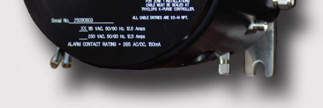
37 31 Alarm Signal Installation: NOTE: The TRYCLOPS X Purge Controller, XP Version provides dry alarm contact(s) for use by the customer. For hook-up and use the alarm contact(s) provided by the purge controller, consult the following Alarm Source Specifications, Alarm Connection table, and Wiring Diagram drawing numbers DO G, page 92 for 115VAC unit and DO G, page 93 for 230VAC unit. Alarm Source Specifications Alarm Contact is rated for 265V AC/DC, 150mA max. Use 20 AWG two conductor copper or tin-plated copper power wire rated for at least 300 V at the required length. Alarm Connections ALARM TERMINAL Loss of Purge Pressure: Open on Alarm (Standard). Closed on Alarm (Optional). Closed (Standard) Open (Optional) when pressure in enclosure being monitored is at or above 0.50 inches H2O (1.25 mbar) TERMINAL NUMBER Terminal Block 2 Position 1 Return for position one Terminal Block 2 Position 2 Loss of Exhaust Flow: Open on Alarm (Standard). Closed on Alarm (Optional). Closed (Standard) Open (Optional) when flow of exhaust for enclosure being monitored has fallen below a safe level. Terminal Block 2 Position 3 Return for position three Terminal Block 2 Position 4 Maintenance Alarm and By-Pass Mode: Open on Alarm (Standard). Closed on Alarm (Optional). Open (Standard) Closed (Optional) when maintenance switch or by-pass switch is operated. Terminal Block 2 Position 5 Return for position five Terminal Block 2 Position 6
38 32 ALARM Purge pressure goes below 0.50 inches H2O (1.25 mbar) ( Normal Operation Mode) Alarm Matrix VISUAL INDICATION Steady State, Red LED REMOTE INDICATION Yes, when installed POWER DISCONNECTED Yes Exhaust vent flow drops below safe level Steady State, Red LED Yes, when installed Yes Maintenance Switch turned to Over-Ride Blinking, Red LED Yes, when installed No During Purge Dilution Cycle Time Blinking, Green LED No Yes Normal Operation Steady State, Green LED No No ALARM Purge pressure goes below 0.50 inches H2O (1.25 mbar) (Power Disconnect By-Pass Switch Mode) Alarm Matrix VISUAL INDICATION Steady State, Red LED REMOTE INDICATION Yes, when installed POWER DISCONNECTED No Exhaust vent flow drops below safe level Steady State, Red LED Yes, when installed No Maintenance Switch turned to Over-Ride Blinking, Red LED Yes, when installed No During Purge Dilution Cycle Time Blinking, Green LED No Yes Normal Operation Steady State, Green and Blinking Red LED. Yes, when installed No
39 33 Section 5 Start Up Procedures (Normal Operation Mode) Continuous Dilution Initial Startup Procedure: The following procedure should be performed when initially starting up a system in Normal Operation Mode using a Continuous Dilution Purge Gas Kit and to calculate the dilution time for any purged electrical equipment that uses the TRYCLOPS X Purge Controller, XP Version to monitor and control the electrical equipment enclosure(s) purge pressure and power. WARNING: Failure to heed the following information may lead to injury of personnel or equipment damage. WARNING: Do not open the electrical equipment enclosure(s) in a hazardous area even when de-energized unless area has been properly tested and is known to not contain explosive materials. WARNING: Before initially starting the equipment, electrical power wiring must be checked for correct size and routing. Step 1: WARNING: The following procedure only addresses the application of power to the TRYCLOPS X Purge Controller, XP Version and to the electrical equipment located within the purged enclosure(s) being monitored and controlled by the TRYCLOPS X Purge Controller, XP Version. NOTE: Refer to all ATEX, CSA, IECEx, NEC, NFPA and UL certificates for any Special Conditions of Use. If the sign X is placed after the certificate number, it indicates that the equipment or protective system is subject to special conditions for safe use specified in the schedule of the certificate. Make sure that area surrounding the TRYCLOPS X Purge Controller, XP Version and the electronics enclosure(s) the TRYCLOPS X Purge Controller, XP Version will be monitoring and controlling is known to be non-hazardous.
40 34 Step 2: After it has been established that the area surrounding TRYCLOPS X Purge Controller, XP Version and the electronics enclosure(s) the TRYCLOPS X Purge Controller, XP Version will be monitoring and controlling is non-hazardous, unscrew the cover off the TRYCLOPS X Purge Controller, XP Version housing and open all electronics enclosure door(s). Step 3: After opening all electronics enclosure door(s), install Continuous Dilution Purge Gas Inlet Kit per installation instructions located in Purge Solutions, Inc. Purge Gas Inlet Kits Users Manual. (This step must be repeated for every enclosure being monitored.) Step 4: With all electronics enclosure door(s) still open, turn on purge protective gas supply to electronics enclosure(s) by turning the Continuous Dilution Purge Gas Inlet Kit shutoff valve to the ON position and verify that enclosure is being supplied with purge gas. Step 5: After it has been verified that the enclosure is being supplied with purge gas, turn off purge gas supply pressure to electronics enclosure at Continuous Dilution Purge Gas Inlet Kit pressure regulator. Step 6: With protective gas supply pressure off at Continuous Dilution Purge Gas Inlet Kit regulator, close and latch electronics enclosure door(s). Step 7: With electronics enclosure door(s) properly closed and latched, turn on power to TRYCLOPS X Purge Controller, XP Version. Step 8: WARNING: DO NOT TURN ON POWER TO TRYCLOPS X PURGE CONTROLLER, XP VERSION, UNLESS AREA HAS BEEN PROPERLY TESTED AND IS KNOWN NOT TO CONTAIN EXPLOSIVE MATERIALS. With power applied to the TRYCLOPS X Purge Controller, XP Version, raise the pressure of the purge protective gas using the Continuous Dilution Purge Gas Inlet Kit pressure regulator until TRYCLOPS X Purge Controller, XP Version green light begins to blink.
41 35 Step 9: With purge protective gas being supplied to electronics enclosure(s) and TRYCLOPS X Purge Controller, XP Version s green indicator light blinking, turn Continuous Dilution Purge Gas Inlet Kit manifold shut-off valve to the OFF position. Step 10: With protective gas supply turned off at Continuous Dilution Purge Gas Inlet Kit shutoff valve, record the pressure reading on the Continuous Dilution Purge Gas Inlet Kit pressure gauge. The recorded pressure will be used to calculate the purge dilution time before power can be applied to electronics within the purged enclosure. Only the pressure recorded when the Continuous Dilution Purge Gas Inlet Kit shutoff valve is in the OFF position should be used to calculate the dilution time required before power can be connected to the electronics with in the enclosure. Step 11: With Continuous Dilution Purge Gas Inlet Kit manifold shut-off valve in the OFF position and the pressure reading of the pressure regulator gauge written down, disconnect power from the TRYCLOPS X Purge Controller, XP Version. Step 12: With TRYCLOPS X Purge Controller, XP Version cover removed, set automatic dilution time cycle in the TRYCLOPS X Purge Controller, XP Version to ensure that at least five (5) times the volume of free space in the largest electronics enclosure is exchanged before power is automatically applied to the electrical equipment from the TRYCLOPS X Purge Controller, XP Version. Refer to Figure 2 for location and details of dilution time switches in TRYCLOPS X Purge Controller, XP Version. NOTE: If you are using one of Purge Solutions, Inc. Continuous Dilution Purge Gas Inlet Kits to supply purge gas to an electronics enclosure the TRYCLOPS X Purge Controller, XP Version is monitoring refer to Purge Solutions, Inc. web site to use Dilution Time Software to calculate dilution time for your size enclosure. The Dilution Software can only be used if you are using a Purge Solutions, Inc. Continuous Dilution Purge Gas Inlet Kit, as the Dilution Time Software calculations are based data from test performed on Purge Solutions, Inc. Continuous Dilution Purge Gas Inlet Kits and proprietary exhaust vents. WARNING: The number of exchanged volumes may be higher in some situations.
42 36 CAUTION: Do not decrease the timer setting required to adequately dilute the enclosure volume by five (5) times its free space. If timer setting is too short, the electrical equipment enclosure(s) may not be diluted adequately before power is applied. This could result in injury to personnel or equipment damage. Figure 2 Step 13: After automatic dilution purge time cycle has been set, screw TRYCLOPS X Purge Controller, XP Version s cover back on housing and secure cover with retaining clip. Step 14: After screwing TRYCLOPS X Purge Controller, XP Version cover back on housing and secure cover with retaining clip, close and properly latch all enclosure door(s).
43 37 Step 15: With all enclosure door(s) properly closed and latched, turn on power to TRYCLOPS X Purge Controller, XP Version. WARNING: DO NOT TURN ON POWER TO TRYCLOPS X PURGE CONTROLLER, XP VERSION, UNLESS AREA HAS BEEN PROPERLY TESTED AND IS KNOWN NOT TO CONTAIN EXPLOSIVE MATERIALS. Step 16: With power applied to the TRYCLOPS X Purge Controller, XP Version turn the Continuous Dilution Purge Gas Inlet Kit manifold shut-off valve to the ON position and the TRYCLOPS X Purge Controller, XP Version green light should begin to blink. Step 17: With purge protective gas being supplied to electronics enclosure(s) and TRYCLOPS X Purge Controller, XP Version s green indicator light blinking, the automatic dilution purge time cycle will start. The automatic dilution time cycle must be set long enough to ensure that at least five (5) times the volume of free space in the largest enclosure of purge protective gas is exchanged before power can be automatically applied to the electrical equipment inside the purged enclosure(s) by the TRYCLOPS X Purge Controller, XP Version. WARNING: The number of exchanged volumes may be higher in some situations. NOTE: Purge dilution time can be reduced by increasing purge supply gas pressure at Continuous Dilution Purge Gas Inlet Kit pressure regulator. Repeat steps 6 through 17 until satisfactory dilution time has been met. Step 18: After the automatic dilution purge time cycle has elapsed and the following conditions are being met, the monitored enclosure pressure is being maintained above 0.50 inches H2O (1.25 mbar) and enclosure exhaust port is registering adequate flow, the green indicator will stop blinking and go into a steady state. Power will then be automatically applied by the TRYCLOPS X Purge Controller, XP Version to the electrical equipment within the protected purged enclosure.
44 38 NOTE: If you are using one of Purge Solutions, Inc. Continuous Dilution Purge Gas Inlet Kits to supply purge gas to an electronics enclosure(s) the TRYCLOPS X Purge Controller, XP Version is monitoring refer to Purge Solutions web site to use Dilution Time Software to calculate dilution time for your largest size enclosure. The Dilution Software can only be used if you are using a Purge Solutions, Inc. Continuous Dilution Purge Gas Inlet Kit, as the Dilution Time Software calculations are based data from test performed on Purge Solutions, Inc. Continuous Dilution Purge Gas Inlet Kits and proprietary vents. Step 19: After the automatic dilution purge time cycle has elapsed and the following conditions are being met, all the monitored enclosure pressure(s) is being maintained above 0.50 inches H2O (1.25 mbar) and all enclosure exhaust port is registering adequate flow(s), the green indicator will stop blinking and go into a steady state. Power will then be automatically applied by the TRYCLOPS X Purge Controller, XP Version to the electrical equipment within the protected purged enclosure(s). NOTE: If AC power, purge pressure(s) becomes less than 0.50 inches H2O (1.25 mbar) or exhaust flow(s) drops too low, the TRYCLOPS X Purge Controller, XP Version shuts off power to the electrical equipment it has been monitoring and controlling. When the power, purge pressure(s) or exhaust flow(s) is restored, the TRYCLOPS X Purge Controller, XP Version automatically begins the dilution time cycle. After the automatic dilution time cycle has elapsed and the following conditions are being met. The monitored electronics enclosure pressure(s) is being maintained above 0.50 inches H2O (1.25 mbar) and enclosure exhaust port is registering adequate flow(s). Power will then be automatically applied by the TRYCLOPS X Purge Controller, XP Version to the electrical equipment within the protected purged enclosure(s). Step 20: After an automatic dilution time has been established, the automatic purge dilution time, the purge protective gas supply pressure and Continuous Dilution Purge Gas Inlet Kit pressure regulator gauge pressure written down during set up should be recorded for used during any future maintenance or service of the purged electronics enclosure(s) being monitored by the TRYCLOPS X Purge Controller, XP Version.
45 39 (Normal Operation Mode) Automatic Leakage Compensation Initial Startup Procedure: The following procedure should be performed when initially starting up a system in Normal Operation Mode using a Purge Solutions, Inc. Automatic Leakage Compensation Purge Gas Inlet Kit and to calculate the dilution time for any purged electrical equipment that uses the TRYCLOPS X Purge Controller, XP Version to monitor and control the electrical equipment enclosure(s) purge pressure and power. WARNING: Failure to heed the following information may lead to injury of personnel or equipment damage. WARNING: Do not open the electrical equipment enclosure(s) in a hazardous area even when de-energized unless area has been properly tested and is known to not contain explosive materials. WARNING: Before initially starting the equipment, electrical power wiring must be checked for correct size and routing. Step 1: WARNING: The following procedure only addresses the application of power to the TRYCLOPS X Purge Controller, XP Version and to the electrical equipment located within the purged enclosure(s) being monitored and controlled by the TRYCLOPS X Purge Controller, XP Version. NOTE: Refer to all ATEX, CSA, IECEx, NEC, NFPA and UL certificates for any Special Conditions of Use. If the sign X is placed after the certificate number, it indicates that the equipment or protective system is subject to special conditions for safe use specified in the schedule of the certificate. Make sure that area surrounding the TRYCLOPS X Purge Controller, XP Version and the electronics enclosure(s) the TRYCLOPS X Purge Controller, XP Version will be monitoring and controlling, is known to be non-hazardous. Step 2: After it has been established that the area surrounding the TRYCLOPS X Purge Controller, XP Version and the electronics enclosure(s) the TRYCLOPS X Purge Controller, XP Version will be monitoring and controlling is non-hazardous, unscrew cover off the TRYCLOPS X Purge Controller, XP Version and open all electronics enclosure door(s).
46 40 Step 3: After opening electronics enclosure door(s), install Automatic Leakage Compensation Purge Gas Inlet Kit per installation instructions located in Purge Solutions, Inc. Purge Gas Inlet Kits Users Manual. Do not connect Automatic Leakage Compensation Purge Gas Inlet Kit solenoid valve wires to terminal blocks located in TRYCLOPS X Purge Controller, XP Version. Step 4: With all enclosure door(s) still open, turn on purge protective gas supply to Automatic Leakage Compensation Purge Gas Inlet Kit and verify purge protective gas is being supplied by reading pressure on pressure regulator gauge. Step 5: With protective gas supply pressure verified, assure that leakage compensation valve is completely closed on the Automatic Leakage Compensation Purge Gas Inlet Kit manifold block. Step 6: After assuring that leakage compensation valve is completely closed on the Automatic Leakage Compensation Purge Gas Inlet Kit manifold block, properly close and latch electronics enclosure door(s). Step 7: With enclosure door(s) properly closed and latched and purge protective gas supply pressure at Automatic Leakage Compensation Purge Gas Inlet Kit pressure regulator, write down pressure reading on gauge. The pressure reading will be needed to calculate the enclosure dilution time using Purge Solutions, Inc. Dilution Software. Step 8: With all electronics enclosure door(s) properly closed and latched and pressure recorded, apply power to the TRYCLOPS X Purge Controller, SM Version. Step 9: WARNING: DO NOT TURN ON POWER TO TRYCLOPS X PURGE CONTROLLER, XP VERSION UNLESS AREA HAS BEEN PROPERLY TESTED AND IS KNOWN NOT TO CONTAIN EXPLOSIVE MATERIALS. With power applied to the TRYCLOPS X Purge Controller, XP Version and protective gas supply pressure at Automatic Leakage Compensation Purge Gas Inlet Kit pressure regulator, open leakage compensation valve on the Automatic Leakage Compensation Purge Gas Inlet Kit manifold block until the TRYCLOPS X Purge Controller, XP Version s green light starts to blink.
47 41 Step 10: With TRYCLOPS X Purge Controller, XP Version s green light blinking, using jam nut, lock leakage compensation valve in place on the Automatic Leakage Compensation Purge Gas Inlet Kit manifold block to maintain leakage compensation volume setting. Step 11: With Automatic Leakage Compensation Purge Gas Inlet Kit manifold block set to maintain leakage compensation volume, disconnect power from TRYCLOPS X Purge Controller, XP Version. Step 12: With power disconnected from TRYCLOPS X Purge Controller, XP Version turn off protective gas supply pressure to electronics enclosure at purge gas supply shut off valve not at Automatic Leakage Compensation Purge Gas Inlet Kit pressure regulator and open electronics enclosure door. The pressure reading on the Automatic Leakage Compensation Purge Gas Inlet Kit pressure gauge will be needed to calculate the enclosure dilution time using Purge Solutions, Inc. Dilution Software. Step 13: With electronics enclosure door open and TRYCLOPS X Purge Controller, XP Version cover still removed connect Automatic Leakage Compensation Purge Gas Inlet Kit solenoid valve wires to correct terminal blocks in TRYCLOPS X Purge Controller, XP Version. Step 14: With Automatic Leakage Compensation Purge Gas Inlet Kit solenoid valve wires connected to terminal blocks in TRYCLOPS X Purge Controller, XP Version set automatic dilution time cycle to ensure that at least five (5) times the volume of free space in the electronics enclosure is exchanged before power is automatically applied to the electrical equipment. Refer to Figure 2 for location and details of dilution time switches. WARNING: The number of exchanged volumes may be higher in some situations. CAUTION: Do not decrease the timer setting required to adequately dilute the enclosure volume by five (5) times its free space. If timer setting is too short, the electrical equipment enclosure(s) may not be diluted adequately before power is applied. This could result in injury to personnel or equipment damage.
48 42 Figure 2 Step 15: With automatic dilution purge time cycle set, properly screw on TRYCLOPS X Purge Controller, XP Version s cover back on housing and secure cover with retaining clip. Step 16: After properly screwing TRYCLOPS X Purge Controller, XP Version s cover on housing and secure with retaining clip, properly close and latch all enclosure door(s). Step 17: With all electronics enclosure door(s) properly closed and latched, turn on power to TRYCLOPS X Purge Controller, XP Version.
49 43 WARNING: DO NOT TURN ON POWER TO TRYCLOPS X PURGE CONTROLLER, XP VERSION UNLESS AREA HAS BEEN PROPERLY TESTED AND IS KNOWN NOT TO CONTAIN EXPLOSIVE MATERIALS. Step 18: With power applied to the TRYCLOPS X Purge Controller, XP Version turn on purge gas at supply shut off valve pressure, then the TRYCLOPS X Purge Controller, XP Version s green light should begin to blink this should also actuate the Automatic Leakage Compensation Purge Gas Inlet Kit solenoid valve allowing purge gas into enclosure during the dilution cycle. Step 19: With purge protective gas being supplied to electronics enclosure through the Automatic Leakage Compensation Purge Gas Inlet Kit solenoid valve and TRYCLOPS X Purge Controller, XP Version s green light blinking, the automatic dilution time cycle will start. The automatic dilution time cycle must be set long enough to ensure that at least five (5) times the volume of free space in the enclosure of purge protective gas is exchanged before power can be automatically applied to the electrical equipment inside the purged enclosure by the TRYCLOPS X Purge Controller, XP Version. WARNING: The number of exchanged volumes may be higher in some situations. CAUTION: Do not decrease the timer setting required to adequately dilute the enclosure volume by five (5) times its free space. If timer setting is too short, the electrical equipment enclosure(s) may not be diluted adequately before power is applied. This could result in injury to personnel or equipment damage. NOTE: If you are using one of Purge Solutions, Inc. Automatic Leakage Compensation Purge Gas Inlet Kits to supply purge gas to an enclosure the TRYCLOPS X Purge Controller, XP Version is monitoring refer to Purge Solutions, Inc. web site to use Dilution Time Software to calculate dilution time for your size enclosure. The Dilution Software can only be used if you are using a Purge Solutions, Inc. Leakage Compensation Purge Gas Inlet Kit, as the Dilution Time Software calculations are based data from test performed on Purge Solutions, Inc. Leakage Compensation Purge Gas Inlet Kits and proprietary exhaust vents.
50 44 Step 20: After the automatic dilution purge time cycle has elapsed and the following conditions are being met, the monitored enclosure pressure is being maintained above 0.50 inches H2O (1.25 mbar) and enclosure exhaust port is registering adequate flow, the green light will stop blinking and go into a steady state. Power will be disconnected from the Automatic Leakage Compensation Purge gas Inlet Kit solenoid valve and power will then be automatically applied by the TRYCLOPS X Purge Controller, XP Version to the electrical equipment within the protected purged electronics enclosure. NOTE: If purge pressure becomes less than 0.50 inches H2O (1.25 mbar) or exhaust flow drops too low, the TRYCLOPS X Purge Controller, XP Version shuts off power to the electrical equipment it has been monitoring and controlling. When the power, purge pressure or exhaust flow is restored, the TRYCLOPS X Purge Controller, XP Version automatically begins the automatic dilution time cycle. After the automatic dilution time cycle has elapsed and the following conditions are being met. The monitored enclosure pressure is being maintained above 0.50 inches H2O (1.25 mbar) and enclosure exhaust port is registering adequate flow. Power will then be automatically applied by the TRYCLOPS X Purge Controller, XP Version to the electrical equipment within the protected purged enclosure. Step 21: After an automatic dilution time has been established, the dilution time, supply pressure and Automatic Leakage Compensation Purge Gas Inlet Kit regulator gauge pressure should be recorded for use during any future maintenance or service of the purge electronics enclosure being monitored and controlled by the TRYCLOPS X Purge Controller, XP Version.
51 45 (Power Disconnect By-Pass Switch Mode) Continuous Dilution Initial Startup Procedure: The following procedure should be performed when initially starting up a system in Power Disconnect By-Pass Switch Mode using a Continuous Dilution Purge Gas Inlet Kit and to calculate the dilution time for any purged electronics equipment enclosure(s) that uses the TRYCLOPS X Purge Controller, XP Version to monitor and control. For applications were immediate disconnect of power to protected electronics in purged electronics enclosure(s) would result in a more hazardous condition; a Power Disconnect By-Pass Switch is provided, which will allow power to the enclosure(s) electronics to continue upon loss of purge pressure(s) and / or exhaust vent flow(s). The following procedure should be performed when initially starting up any purged electrical equipment that uses the TRYCLOPS X Purge Controller, XP Version with the power disconnect by-pass switch in the By-Pass BP position to monitor and control the electrical equipment enclosure(s). WARNING: Failure to heed the following information may lead to injury of personnel or equipment damage. WARNING: Do not open the electrical equipment enclosure(s) in a hazardous area even when de-energized unless area has been properly tested and is known to not contain explosive materials. WARNING: Applicable permits must be obtained and appropriate precautions must be taken to prevent possible injury to personnel or equipment damage when using the TRYCLOPS X Purge Controller, XP Version s power disconnect by-pass switch. WARNING: Placing the TRYCLOPS X Purge Controller, XP Version power disconnect by-pass switch into the By-Pass position disables safe operation of the system. By-Pass mode is to be used ONLY when immediate disconnect of power to protected electrical equipment in enclosure(s) would result in a more hazardous condition AND ONLY if area is known to be non-hazardous. WARNING: Before initially starting the equipment, electrical power wiring must be checked for correct size and routing. WARNING: The following procedure only addresses the application of power to the TRYCLOPS X Purge Controller, XP Version and to the electrical equipment located within the purged enclosure(s) being monitored and controlled by the TRYCLOPS X Purge Controller, XP Version.
52 46 Step 1: NOTE: Refer to all ATEX, CSA, IECEx, NEC, NFPA and UL certificates for any Special Conditions of Use. If the sign X is placed after the certificate number, it indicates that the equipment or protective system is subject to special conditions for safe use specified in the schedule of the certificate. If power disconnect by-pass switch is to be put into the By-Pass position; first make sure that area-surrounding the TRYCLOPS X Purge Controller, XP Version and the electronics enclosure(s) that the TRYCLOPS X Purge Controller, XP Version will be monitoring and controlling is known to be non-hazardous. Step 2: After it has been established that the area surrounding the TRYCLOPS X Purge Controller, XP Version and the electronics enclosure(s) that the TRYCLOPS X Purge Controller, XP Version will be monitoring and controlling is non-hazardous, remove the cover from the TRYCLOPS X Purge Controller, XP Version housing and open all electronics enclosure door(s). Step 3: After opening all electronics enclosure door(s), install Continuous Dilution Purge Gas Inlet Kit per installation instructions located in Purge Solutions, Inc. Purge Gas Inlet Kits Users Manual. Step 4: With Continuous Dilution Purge Gas Kit installed and TRYCLOPS X Purge Controller, XP Version s cover removed, move the power disconnect by-pass switch from Normal Operation NO position to the By-Pass BP position. Refer to Figure 3 for location and details of Power Disconnect By-Pass Switch.
53 47 Figure 3 Step 5: With electronics enclosure door(s) still open, turn on purge protective gas supply to electronics enclosure by turning the Continuous Dilution Purge Gas Inlet Kit shutoff valve to the ON position and verify that enclosure is being supplied with purge gas. Step 6: After it has been verified that the electronics enclosure is being supplied with purge gas, turn off purge gas supply pressure to electronics enclosure at Continuous Dilution Purge Gas Inlet Kit pressure regulator. Step 7: With protective gas supply pressure off at Continuous Dilution Purge Gas Inlet Kit regulator, close and latch electronics enclosure door(s).
54 48 Figure 2 Step 8: With electronics enclosure door(s) properly closed and latched, turn on power to TRYCLOPS X Purge Controller, SM Version. Step 9: WARNING: DO NOT TURN ON POWER TO TRYCLOPS X PURGE CONTROLLER, XP VERSION UNLESS AREA HAS BEEN PROPERLY TESTED AND IS KNOWN NOT TO CONTAIN EXPLOSIVE MATERIALS. With power applied to the TRYCLOPS X Purge Controller, XP Version raise the pressure of the purge protective gas using the Continuous Dilution Purge Gas Inlet Kit pressure regulator until TRYCLOPS X Purge Controller, XP Version s green light begins to blink.
55 49 Step 10: With purge protective gas being supplied to electronics enclosure and TRYCLOPS X Purge Controller, XP Version s green indicator light blinking, turn Continuous Dilution Purge Gas Inlet Kit manifold shut-off valve to the OFF position. Step 11: With Continuous Dilution Purge Gas Inlet Kit manifold shut-off valve in the OFF position, write down the pressure reading of the pressure regulator gauge. The pressure reading will be needed to calculate the enclosure dilution time using Purge Solutions, Inc. Dilution Software. Step 12: With Continuous Dilution Purge Gas Inlet Kit manifold shut-off valve in the OFF position and the pressure reading of the pressure regulator gauge written down, disconnect power from the TRYCLOPS X Purge Controller, XP Version. Step 13: With power disconnected from the TRYCLOPS X Purge Controller, XP Version open enclosure door to access the TRYCLOPS X Purge Controller, XP Version to set automatic dilution time cycle. NOTE: If you are using one of Purge Solutions, Inc. Continuous Dilution Purge Gas Inlet Kits to supply purge gas to an electronics enclosure the TRYCLOPS X Purge Controller, XP Version is monitoring refer to Purge Solutions, Inc. web site to use Dilution Time Software to calculate dilution time for your size enclosure. The Dilution Software can only be used if you are using a Purge Solutions, Inc. Continuous Dilution Purge Gas Inlet Kit, as the Dilution Time Software calculations are based data from test performed on Purge Solutions, Inc. Continuous Dilution Purge Gas Inlet Kits and proprietary exhaust vents. Step 14: With cover removed from housing to access the TRYCLOPS X Purge Controller, XP Version set automatic dilution time cycle to least five (5) times the volume of free space in the electronics enclosure is exchanged before power is automatically applied to the electrical equipment from the TRYCLOPS X Purge Controller, XP Version. Refer to Figure 2 for location and details of dilution time switches in TRYCLOPS X Purge Controller, XP Version. WARNING: The number of exchanged volumes may be higher in some situations.
56 50 CAUTION: Do not decrease the timer setting required to adequately dilute the enclosure volume by five (5) times its free space. If timer setting is too short, the electrical equipment enclosure may not be diluted adequately before power is applied. This could result in injury to personnel or equipment damage. Figure 2 Step 15: After automatic dilution purge time cycle set, properly screw cover and secure with retaining clip to TRYCLOPS X Purge Controller, XP Version s housing. Step 16: After properly securing cover with retaining clip to TRYCLOPS X Purge Controller, XP Version housing, properly close and latch electronics enclosure door(s).
57 51 Step 17: With electronics enclosure door(s) properly closed and latched, turn on power to TRYCLOPS X Purge Controller, XP Version. WARNING: DO NOT TURN ON POWER TO TRYCLOPS X PURGE CONTROLLER, XP VERSION UNLESS AREA HAS BEEN PROPERLY TESTED AND IS KNOWN NOT TO CONTAIN EXPLOSIVE MATERIALS. Step 18: With power applied to the TRYCLOPS X Purge Controller, XP Version turn the Continuous Dilution Purge Gas Inlet Kit manifold shut-off valve to the ON position and the TRYCLOPS X Purge Controller, XP Version s green light should begin to blink. Step 19: With purge protective gas being supplied to electronics enclosure(s) and TRYCLOPS X Purge Controller, XP Version s green indicator light blinking, the automatic dilution purge time cycle will start. The automatic dilution time cycle must be set long enough to ensure that at least five (5) times the volume of free space of the largest enclosure of purge protective gas is exchanged before power can be automatically applied to the electrical equipment inside the purged largest enclosure by the TRYCLOPS X Purge Controller, XP Version. WARNING: The number of exchanged volumes may be higher in some situations. NOTE: Purge dilution time can be reduced by increasing purge supply gas pressure at Continuous Dilution Purge Gas Inlet Kit pressure regulator. Repeat steps 6 through 13 until satisfactory dilution time has been met. Step 20: After the automatic dilution purge time cycle has elapsed and the following conditions are being met, the monitored enclosure(s) pressure is being maintained above 0.50 inches H2O (1.25 mbar) and enclosure exhaust port is registering adequate flow, the green indicator will stop blinking and go into a steady state. Power will then be automatically applied by the TRYCLOPS X Purge Controller, XP Version to the electrical equipment within the protected purged enclosure(s).
58 52 WARNING: Placing the TRYCLOPS X Purge Controller, XP Version power disconnect by-pass switch into the By-Pass position disables safe operation of the system. By-Pass mode is to be used ONLY when immediate disconnect of power to protected electrical equipment in enclosure would result in a more hazardous condition AND ONLY if area is known to be non-hazardous. NOTE: When the TRYCLOPS X Purge Controller, XP Version is in by-pass mode power WILL NOT be disconnected if purge pressure becomes less than 0.50 inches H2O (1.25 mbar) or exhaust flow drops too low from the electrical equipment it has been monitoring and controlling. NOTE: When the TRYCLOPS X Purge Controller, XP Version is in by-pass mode the TRYCLOPS X Purge Controller, XP Version will ONLY alarm if purge pressure becomes less than 0.50 inches H2O (1.25 mbar) or exhaust flow drops too low from the electrical equipment it has been monitoring and controlling. NOTE: When the TRYCLOPS X Purge Controller, XP Version is in by-pass mode the TRYCLOPS X Purge Controller, XP Version and purge pressure or exhaust flow is restored, the TRYCLOPS X Purge Controller, XP Version WILL NOT automatically begins the dilution purge time before restoring power to the electrical equipment within the protected purged enclosure(s). NOTE: When the TRYCLOPS X Purge Controller, XP Version is in by-pass mode AC line power must first be disconnected from the TRYCLOPS X Purge Controller, XP Version and then re-connected before the automatic dilution purge time will begin. WARNING: When the TRYCLOPS X Purge Controller, XP Version is in by-pass mode; personnel must remove power from the electrical system IMMEDIATELY if hazardous conditions are suspected. Step 21: After an automatic dilution time has been established, the automatic dilution time, purge protective gas supply pressure and Continuous Dilution Purge Gas Inlet Kit regulator gauge pressure should be recorded for used during any future maintenance or service of the purged electronics enclosure being monitored and controlled by the TRYCLOPS X Purge Controller, XP Version.
59 53 (Power Disconnect By-Pass Switch Mode) Automatic Leakage Compensation Initial Startup Procedure: The following procedure should be performed when initially starting up a system in Power Disconnect By-Pass Switch Mode using a Purge Solutions, Inc. Automatic Leakage Compensation Purge Gas Inlet Kit and to calculate the dilution time for any purged electronics equipment enclosure(s) that uses the TRYCLOPS X Purge Controller, XP Version to monitor and control. For applications were immediate disconnect of power to protected electrical in purged enclosure(s) would result in a more hazardous condition; a Power Disconnect By-Pass Switch is provided, which will allow power to the enclosure(s) electronics to continue upon loss of purge pressure(s) and / or exhaust vent flow(s). The following procedure should be performed when initially starting up any purged electrical equipment that uses the TRYCLOPS X Purge Controller, XP Version with the power disconnect by-pass switch in the By-Pass BP position to monitor and control the electrical equipment enclosure(s). WARNING: Failure to heed the following information may lead to injury of personnel or equipment damage. WARNING: Do not open the electrical equipment enclosure(s) in a hazardous area even when de-energized unless area has been properly tested and is known to not contain explosive materials. WARNING: Before initially starting the equipment, electrical power wiring must be checked for correct size and routing. WARNING: The following procedure only addresses the application of power to the TRYCLOPS X Purge Controller, XP Version and to the electrical equipment located within the purged enclosure(s) being monitored and controlled by the TRYCLOPS X Purge Controller, XP Version. NOTE: Refer to all ATEX, CSA, IECEx, NEC, NFPA and UL certificates for any Special Conditions of Use. If the sign X is placed after the certificate number, it indicates that the equipment or protective system is subject to special conditions for safe use specified in the schedule of the certificate.
60 54 Step 1: If power disconnect by-pass switch is to be put into the By-Pass position; first make sure that area-surrounding the TRYCLOPS X Purge Controller, XP Version and the electronics enclosure(s) that the TRYCLOPS X Purge Controller, XP Version will be monitoring and controlling is known to be non-hazardous. Step 2: After it has been established that the area surrounding the TRYCLOPS X Purge Controller, XP Version and all the electronics enclosure(s) that the TRYCLOPS X Purge Controller, XP Version will be monitoring and controlling is non-hazardous, unscrew and remove the cover from the TRYCLOPS X Purge Controller, XP Version housing and open all electronics enclosure door(s) the TRYCLOPS X Purge Controller, XP Version is monitoring. Step 3: After opening electronics enclosure door(s) open TRYCLOPS X- Purge Controller, XP Version cover and then install Automatic Leakage Compensation Purge Gas Inlet Kit per installation instructions located in Purge Gas Inlet Kits Users Manual. Do not connect Automatic Leakage Compensation Purge Gas Inlet Kit solenoid valve wires to terminal blocks in TRYCLOPS X Purge Controller, XP Version. Step 4: With electronics enclosure door(s) still open, move the power disconnect by-pass switch from Normal Operation NO position to the By-Pass BP position. Refer to Figure 3 for location and details of Power Disconnect By-Pass Switch.
61 55 Figure 3 Step 5: With electronics enclosure door(s) still open, turn on purge protective gas supply to Automatic Leakage Compensation Purge Gas Inlet Kit and verify purge protective gas is being supplied by reading pressure on pressure regulator gauge. Step 6: With protective gas supply pressure verified, assure that leakage compensation valve is completely closed on the Automatic Leakage Compensation Purge Gas Inlet Kit manifold block. Step 7: After assuring that leakage compensation valve is completely closed on the Automatic Leakage Compensation Purge Gas Inlet Kit manifold block, properly close and latch electronics enclosure door(s).
62 56 Step 8: With electronics enclosure door(s) properly closed and latched and purge protective gas supply pressure at Automatic Leakage Compensation Purge Gas Inlet Kit pressure regulator, write down pressure reading on gauge. The pressure reading will be needed to calculate the enclosure dilution time using Purge Solutions, Inc. Dilution Software. Step 9: With electronics enclosure door(s) properly closed and latched and pressure recorded, apply power to TRYCLOPS X Purge Controller, XP Version. WARNING: DO NOT TURN ON POWER TO TRYCLOPS X PURGE CONTROLLER, XP VERSION UNLESS AREA HAS BEEN PROPERLY TESTED AND IS KNOWN NOT TO CONTAIN EXPLOSIVE MATERIALS. Step 10: With power applied to the TRYCLOPS X Purge Controller, XP Version and protective gas supply pressure at Automatic Leakage Compensation Purge Gas Inlet Kit pressure regulator, open leakage compensation valve on the Automatic Leakage Compensation Purge Gas Inlet Kit manifold block until the TRYCLOPS X Purge Controller, XP Version s green light starts to blink. Step 11: With TRYCLOPS X Purge Controller, XP Version s green light blinking, using jam nut, lock leakage compensation valve in place on the Automatic Leakage Compensation Purge Gas Inlet Kit manifold block to maintain leakage compensation volume setting. Step 12: With Automatic Leakage Compensation Purge Gas Inlet Kit manifold block set to maintain leakage compensation volume, disconnect power from TRYCLOPS X Purge Controller, XP Version. Step 13: With power disconnected from TRYCLOPS X Purge Controller, XP Version turn off protective gas supply pressure to electronics enclosure at purge gas supply shut off valve not at Automatic Leakage Compensation Purge Gas Inlet Kit pressure regulator and open electronics enclosure door. The pressure reading on the Automatic Leakage Compensation Purge Gas Inlet Kit pressure gauge will be needed to calculate the enclosure dilution time using Purge Solutions, Inc. Dilution Software.
63 57 Step 14: With electronics enclosure door(s) still opened and cover removed from TRYCLOPS X Purge Controller, XP Version housing, connect Automatic Leakage Compensation Purge Gas Inlet Kit solenoid valve wires to correct terminal blocks in TRYCLOPS X Purge Controller, XP Version. Step 15: With Automatic Leakage Compensation Purge Gas Inlet Kit solenoid valve wires connected to correct terminal blocks in TRYCLOPS X Purge Controller, XP Version set automatic dilution time cycle to ensure that at least five (5) times the volume of free space in the electronics enclosure is exchanged before power is automatically applied to the electrical equipment. Refer to Figure 2 for location and details of dilution time switches. WARNING: The number of exchanged volumes may be higher in some situations. CAUTION: Do not decrease the timer setting required to adequately dilute the enclosure volume by five (5) times its free space. If timer setting is too short, the electrical equipment enclosure may not be diluted adequately before power is applied. This could result in injury to personnel or equipment damage.
64 58 Figure 2 Step 16: With automatic dilution purge time cycle set, screw TRYCLOPS X Purge Controller, XP Version s properly screw cover back on housing and secure with retaining clip. Step 17: After properly securing cover to TRYCLOPS X Purge Controller, XP Version housing with retainer clip, properly close and latch electronics enclosure door(s). Step 18: With electronics enclosure door(s) properly closed and latched, turn on power to TRYCLOPS X Purge Controller, XP Version.
65 59 WARNING: DO NOT TURN ON POWER TO TRYCLOPS X PURGE CONTROLLER, XP VERSION UNLESS AREA HAS BEEN PROPERLY TESTED AND IS KNOWN NOT TO CONTAIN EXPLOSIVE MATERIALS. Step 19: With power applied to the TRYCLOPS X Purge Controller, XP Version turn on purge gas at supply shut off valve, then the TRYCLOPS X Purge Controller, XP Version s green light should begin to blink this should also actuate the Automatic Leakage Compensation Purge Gas Inlet Kit solenoid valve allowing purge gas into enclosure(s) during the dilution cycle. Step 20: With purge protective gas being supplied to electronics enclosure(s) through the Automatic Leakage Compensation Purge Gas Inlet Kit solenoid valve and TRYCLOPS X Purge Controller, XP Version s green light blinking, the automatic dilution time cycle will start. The automatic dilution time cycle must be set long enough to ensure that at least five (5) times the volume of free space in the enclosure of purge protective gas is exchanged before power can be automatically applied to the electrical equipment inside the purged enclosure by the TRYCLOPS X Purge Controller, XP Version. WARNING: The number of exchanged volumes may be higher in some situations. NOTE: If you are using one of Purge Solutions, Inc. Automatic Leakage Compensation Purge Gas Inlet Kits to supply purge gas to an enclosure(s) the TRYCLOPS X Purge Controller, XP Version is monitoring refer to Purge Solutions, Inc. web site to use Dilution Time Software to calculate dilution time for your largest size enclosure. The Dilution Software can only be used if you are using an Automatic Purge Solutions, Inc. Leakage Compensation Purge Gas Inlet Kit, as the Dilution Time Software calculations are based data from test performed on Purge Solutions, Inc. Automatic Leakage Compensation Purge Gas Inlet Kits and proprietary vents. Step 21: After the automatic dilution purge time cycle has elapsed and the following conditions are being met, the monitored electronics enclosure(s) pressure is being maintained above 0.50 inches H2O (1.25 mbar) and electronics enclosure(s) exhaust port is registering adequate flow, the green will stop blinking and go into a steady state. Power will then be automatically applied by the TRYCLOPS X Purge Controller, XP Version to the electrical equipment within the protected purged enclosure(s).
66 60 WARNING: Placing the TRYCLOPS X Purge Controller, XP Version power disconnect by-pass switch into the By-Pass position disables safe operation of the system. By-Pass mode is to be used ONLY when immediate disconnect of power to protected electrical equipment in enclosure(s) would result in a more hazardous condition AND ONLY if area is known to be non-hazardous. NOTE: When the TRYCLOPS X Purge Controller, XP Version is in by-pass mode power WILL NOT be disconnected if purge pressure becomes less than 0.50 inches H2O (1.25 mbar) or exhaust flow drops too low from the electrical equipment it has been monitoring and controlling. NOTE: When the TRYCLOPS X Purge Controller, XP Version is in by-pass mode the TRYCLOPS X Purge Controller, XP Version will ONLY alarm if purge pressure becomes less than 0.50 inches H2O (1.25 mbar) or exhaust flow drops too low from the electrical equipment it has been monitoring and controlling. NOTE: When the TRYCLOPS X Purge Controller, XP Version is in by-pass mode the TRYCLOPS X Purge Controller, XP Version and purge pressure or exhaust flow is restored, the TRYCLOPS X Purge Controller, XP Version WILL NOT automatically begins the dilution purge time before restoring power to the electrical equipment within the protected purged enclosure(s). NOTE: When the TRYCLOPS X Purge Controller, XP Version is in by-pass mode AC line power must first be disconnected from the TRYCLOPS X Purge Controller, XP Version and then re-connected before the automatic dilution purge time will begin. WARNING: When the TRYCLOPS X Purge Controller, XP Version is in by-pass mode; personnel must remove power from the electrical system IMMEDIATELY if hazardous conditions are suspected. Step 22: After an automatic dilution time has been established, the dilution time, supply pressure and Automatic Leakage Compensation Purge Gas Inlet Kit regulator gauge pressure should be recorded for use during any future maintenance or service of the purge electronics enclosure being monitored and controlled by the TRYCLOPS X Purge Controller, XP Version.
67 61 (Normal Operation Mode) Continuous Dilution Maintenance or Service Procedure: The following procedure should be performed when using the TRYCLOPS X Purge Controller, XP Version s maintenance switch to perform maintenance or service on any system in Normal Operation Mode using a Continuous Dilution Purge Gas Inlet Kit for any purged electrical equipment that uses the TRYCLOPS X Purge Controller, XP Version to monitor and control the electrical equipment enclosure(s) purge pressure and power. WARNING: Failure to heed the following, information may lead to injury to personnel or equipment damage. CAUTION: Do not open the electrical equipment enclosure(s) in a hazardous area even when de-energized unless area has been properly tested and is known to not contain explosive materials. WARNING: Applicable permits must be obtained and appropriate precautions must be taken to prevent possible injury to personnel or equipment damage when using the TRYCLOPS X Purge Controller, XP Version s maintenance switch. WARNING: Placing the TRYCLOPS X Purge Controller, XP Version into Maintenance position disables safe operation of the system. Maintenance mode is to be used ONLY when required for maintenance or service AND ONLY if area is known to be nonhazardous. CAUTION: Electrical equipment components may be hot even when power is not applied. Take appropriate precautions to prevent injury from contact with hot items. NOTE: If required the TRYCLOPS X Purge Controller, XP Version s maintenance switch can be set to Maintenance position to provide power to the electrical equipment mounted in the electrical enclosure(s) the TRYCLOPS X Purge Controller, XP Version is monitoring while the enclosure door(s) is open. When the maintenance switch is in the maintenance position, the safety power shut off function is disabled! Do not place the maintenance switch in the maintenance position unless it is absolutely necessary and the area is known to be non-hazardous. As soon as maintenance or service is complete, the maintenance switch MUST be placed in the Normal Operation position.
68 62 Step 1: If maintenance or service must be performed with power applied to the electrical equipment mounted within the purged enclosure(s) the TRYCLOPS X Purge Controller, XP Version is monitoring, first make sure that area-surrounding the electronics enclosure(s), which the TRYCLOPS X Purge Controller, XP Version is monitoring and controlling is known to be non-hazardous. Step 2: After it has been established that the area surrounding the electronics enclosure(s) is non-hazardous, unscrew the cover over the TRYCLOPS X Purge Controller, XP Version s maintenance switch. Insert key and turn switch to the Maintenance position. Maintenance switch key can only be removed from maintenance switch in Normal Operation position and cover cannot be screwed back on until key is removed from switch. This means, that the maintenance switch key must remain in the switch while maintenance or service is being performed. When the TRYCLOPS X Purge Controller, XP Version is in maintenance mode the indicator light will begin blinking red and, if connected, a remote alarm will be sent. Step 3: With the TRYCLOPS X Purge Controller, XP Version in maintenance mode, turn off purge supply gas at the shut off valve on Continuous Dilution Purge Gas Inlet Kit manifold block. Not at the Continuous Dilution Purge Gas Inlet Kit pressure regulator. The Continuous Dilution Purge Gas Inlet Kit pressure regulator setting should remain the same to keep the purge gas CFM (LPM) the same as what was established during the initial automatic dilution time set up. WARNING: Do not leave the electrical equipment unattended while the TRYCLOPS X Purge Controller, XP Version is in maintenance switch is in the Maintenance position. Personnel must remove power from the electrical system IMMEDIATELY if hazardous conditions are suspected. Step 4: With protective gas supply off at the shut off valve, open electronics enclosure door(s). CAUTION: Electrical equipment components may be hot even when power is not applied. Take appropriate precautions to prevent injury from contact with hot items. Step 5: With electronics enclosure door(s) opened and the TRYCLOPS X Purge Controller, XP Version in maintenance mode applying power to the electronics, perform required maintenance or service.
69 63 Step 6: After maintenance or service has been performed and completed, properly close and latch electronics enclosure door(s). Step 7: After all enclosure door(s) have been properly closed and latched, turn on purge supply gas at the shut off valve on Continuous Dilution Purge Gas Inlet Kit manifold block. Not at the Continuous Dilution Purge Gas Inlet Kit pressure regulator. The Continuous Dilution Purge Gas Inlet Kit pressure regulator setting should remain the same to keep the purge gas CFM (LPM) the same as what was established during the initial automatic dilution time set up. Step 8: With electronics all enclosure doors latched and purge supply gas turned on at the shut off valve, return TRYCLOPS X Purge Controller, XP Version maintenance switch to the Normal Operation position. After the maintenance switch has been returned to the Normal Operations position and the following conditions are being met. The monitored enclosure pressure(s) is being maintained above 0.50 inches H2O (1.25 mbar) and enclosure exhaust port(s) is registering proper flow(s), the TRYCLOPS X Purge Controller, XP Version will go from a light blinking red to a steady state of green and power will remain connected through the TRYCLOPS X Purge Controller, XP Version to the electrical equipment within the purged enclosure(s). Step 9: After TRYCLOPS X Purge Controller, XP Version s maintenance switch has been returned to Normal Operations position, remove key and screw maintenance switch cover back on as before. NOTE: If power does not remain on when TRYCLOPS X Purge Controller, XP Version maintenance switch is returned to Normal Operations position, check for the following possible problems. Purge pressure(s) is set too low at the pressure regulator. Electronics enclosure door(s) is open or allowing too much leakage. Flow(s) from exhaust port has become restricted or blocked.
70 64 (Normal Operation Mode) Automatic Leakage Compensation Maintenance or Service Procedure: The following procedure should be performed when using the TRYCLOPS X Purge Controller, XP Version s maintenance switch to perform maintenance or service on any system in Normal Operation Mode using an Automatic Leakage Compensation Purge Gas Inlet Kit for any purged electrical equipment that uses the TRYCLOPS X Purge Controller, XP Version to monitor and control the electrical equipment enclosure(s) purge pressure and power. WARNING: Failure to heed the following, information may lead to injury to personnel or equipment damage. CAUTION: Do not open the electrical equipment enclosure(s) in a hazardous area even when de-energized unless area has been properly tested and is known to not contain explosive materials. WARNING: Applicable permits must be obtained and appropriate precautions must be taken to prevent possible injury to personnel or equipment damage when using the TRYCLOPS X Purge Controller, XP Version s maintenance switch. WARNING: Placing the TRYCLOPS X Purge Controller, XP Version into Maintenance position disables safe operation of the system. Maintenance mode is to be used ONLY when required for maintenance or service AND ONLY if area is known to be nonhazardous. CAUTION: Electrical equipment components may be hot even when power is not applied. Take appropriate precautions to prevent injury from contact with hot items. NOTE: If required the TRYCLOPS X Purge Controller, XP Version s maintenance switch can be set to Maintenance position to provide power to the electrical equipment mounted in the electrical enclosure(s) the TRYCLOPS X Purge Controller, XP Version is monitoring while the enclosure door(s) is open. When the maintenance switch is in the maintenance position, the safety power shut off function is disabled! Do not place the maintenance switch in the maintenance position unless it is absolutely necessary and the area is known to be non-hazardous. As soon as maintenance or service is complete, the maintenance switch MUST be placed in the Normal Operation position.
71 65 Step 1: If maintenance or service must be performed with power applied to the electrical equipment mounted within the purged enclosure(s) the TRYCLOPS X Purge Controller, XP Version is monitoring, first make sure that area-surrounding the electronics enclosure(s), which the TRYCLOPS X Purge Controller, XP Version is monitoring and controlling is known to be non-hazardous. Step 2: After it has been established that the area surrounding the electronics enclosure(s) is non-hazardous, unscrew the cover over the TRYCLOPS X Purge Controller, XP Version s maintenance switch. Insert key and turn switch to the Maintenance position. Maintenance switch key can only be removed from maintenance switch in Normal Operation position and cover cannot be screwed back on until key is removed from switch. This means, that the maintenance switch key must remain in the switch while maintenance or service is being performed. When the TRYCLOPS X Purge Controller, XP Version is in maintenance mode the indicator light will begin blinking red and, if connected, a remote alarm will be sent. Step 3: With the TRYCLOPS X Purge Controller, XP Version in maintenance mode, turn off purge supply gas at the shut off valve. Not at the Automatic Leakage Compensation Purge Gas Inlet Kit pressure regulator. The Automatic Leakage Compensation Purge Gas Inlet Kit pressure regulator setting should remain the same to keep the purge gas CFM (LPM) the same as what was established during the initial automatic dilution time set up. WARNING: Do not leave the electrical equipment unattended while the TRYCLOPS X Purge Controller, XP Version is in maintenance switch is in the Maintenance position. Personnel must remove power from the electrical system IMMEDIATELY if hazardous conditions are suspected. Step 4: With protective gas supply off at the shut off valve, open electronics enclosure door(s). CAUTION: Electrical equipment components may be hot even when power is not applied. Take appropriate precautions to prevent injury from contact with hot items. Step 5: With all electronics enclosure door(s) opened and the TRYCLOPS X Purge Controller, XP Version in maintenance mode applying power to the electronics, perform required maintenance or service.
72 66 Step 6: After maintenance or service has been performed and completed, properly close and latch all open electronics enclosure doors. Step 7: After electronic enclosure door(s) have been properly closed and latched, turn on purge supply gas at the shut off valve. Not at the Automatic Leakage Compensation Purge Gas Inlet Kit pressure regulator. The Automatic Leakage Compensation Purge Gas Inlet Kit pressure regulator setting should remain the same to keep the purge gas CFM (LPM) the same as what was established during the initial automatic dilution time set up. Step 8: With electronics enclosure door(s) latched and purge supply gas turned on at the shut off valve, return TRYCLOPS X Purge Controller, XP Version maintenance switch to the Normal Operation position. After the maintenance switch has been returned to the Normal Operations position and the following conditions are being met. The monitored enclosure pressure(s) is being maintained above 0.50 inches H2O (1.25 mbar) and enclosure exhaust port is registering proper flow(s), the TRYCLOPS X Purge Controller, XP Version will go from a light blinking red to a steady state of green and power will remain connected through the TRYCLOPS X Purge Controller, XP Version to the electrical equipment within the purged enclosure(s). Step 9: After TRYCLOPS X Purge Controller, XP Version s maintenance switch has been returned to Normal Operations position, remove key and screw maintenance switch cover back on as before. NOTE: If power does not remain on when TRYCLOPS X Purge Controller, XP Version maintenance switch is returned to Normal Operations position, check for the following possible problems. Purge pressure(s) is set too low at the pressure regulator. Electronics enclosure door(s) is open or allowing too much leakage. Flow(s) from exhaust port has become restricted or blocked.
73 67 (Continuous Dilution) Power Disconnect By-Pass Switch Mode Maintenance or Service Procedure: The following procedure should be performed when using the TRYCLOPS X Purge Controller, XP Version s maintenance switch to perform maintenance or service on any system in Power Disconnect By-Pass Switch Mode using a Continuous Dilution Purge Gas Inlet Kit for any purged electrical equipment that uses the TRYCLOPS X Purge Controller, XP Version to monitor and control the electrical equipment enclosure(s) purge pressure and power. WARNING: Failure to heed the following, information may lead to injury to personnel or equipment damage. CAUTION: Do not open the electrical equipment enclosure(s) in a hazardous area even when de-energized unless area has been properly tested and is known to not contain explosive materials. WARNING: Applicable permits must be obtained and appropriate precautions must be taken to prevent possible injury to personnel or equipment damage when using the TRYCLOPS X Purge Controller, XP Version s maintenance switch. WARNING: Placing the TRYCLOPS X Purge Controller, XP Version into Maintenance position disables safe operation of the system. Maintenance mode is to be used ONLY when required for maintenance or service AND ONLY if area is known to be nonhazardous. CAUTION: Electrical equipment components may be hot even when power is not applied. Take appropriate precautions to prevent injury from contact with hot items. NOTE: If required the TRYCLOPS X Purge Controller, XP Version s maintenance switch can be set to Maintenance position to provide power to the electrical equipment mounted in the electrical enclosure(s) the TRYCLOPS X Purge Controller, XP Version is monitoring while the enclosure door(s) is open. When the maintenance switch is in the maintenance position, the safety power shut off function is disabled! Do not place the maintenance switch in the maintenance position unless it is absolutely necessary and the area is known to be non-hazardous. As soon as maintenance or service is complete, the maintenance switch MUST be placed in the Normal Operation position.
74 68 Step 1: If maintenance or service must be performed with power applied to the electrical equipment mounted within the purged enclosure(s) the TRYCLOPS X Purge Controller, XP Version is monitoring, first make sure that area-surrounding the electronics enclosure(s), which the TRYCLOPS X Purge Controller, XP Version is monitoring and controlling is known to be non-hazardous. Step 2: After it has been established that the area surrounding the electronics enclosure(s) is non-hazardous, unscrew the cover over the TRYCLOPS X Purge Controller, XP Version s maintenance switch. Insert key and turn switch to the Maintenance position. Maintenance switch key can only be removed from maintenance switch in Normal Operation position and cover cannot be screwed back on until key is removed from switch. This means, that the maintenance switch key must remain in the switch while maintenance or service is being performed. When the TRYCLOPS X Purge Controller, XP Version is in maintenance mode the indicator light will begin blinking red and, if connected, a remote alarm will be sent. Step 3: With the TRYCLOPS X Purge Controller, XP Version in maintenance mode, turn off purge supply gas at the shut off valve. Not at the Continuous Dilution Purge Gas Inlet Kit pressure regulator. The Continuous Dilution Purge Gas Inlet Kit pressure regulator setting should remain the same to keep the purge gas CFM (LPM) the same as what was established during the initial automatic dilution time set up. WARNING: Do not leave the electrical equipment unattended while the TRYCLOPS X Purge Controller, XP Version is in maintenance switch is in the Maintenance position. Personnel must remove power from the electrical system IMMEDIATELY if hazardous conditions are suspected. Step 4: With protective gas supply off at the shut off valve, open electronics enclosure doors(s). CAUTION: Electrical equipment components may be hot even when power is not applied. Take appropriate precautions to prevent injury from contact with hot items. Step 5: With electronics enclosure door(s) opened and the TRYCLOPS X Purge Controller, XP Version in maintenance mode applying power to the electronics, perform required maintenance or service.
75 69 Step 6: After maintenance or service has been performed and completed, properly close and latch all open electronics enclosure doors. Step 7: After electronics enclosure door(s) has been properly closed and latched, turn on purge supply gas at the shut off valve located on Continuous Dilution Purge Gas Inlet Kit manifold block. Not at the Continuous Dilution Purge Gas Inlet Kit pressure regulator. The Continuous Dilution Purge Gas Inlet Kit pressure regulator setting should remain the same to keep the purge gas CFM (LPM) the same as what was established during the initial automatic dilution time set up. Step 8: With electronics enclosure door(s) latched and purge supply gas turned on at the shut off valve, return TRYCLOPS X Purge Controller, XP Version maintenance switch to the Normal Operation position. After the maintenance switch has been returned to the Normal Operations position and the following conditions are being met. The monitored electronics enclosure pressure(s) is being maintained above 0.50 inches H2O (1.25 mbar) and enclosure exhaust port(s) is registering proper flow(s), the TRYCLOPS X Purge Controller, XP Version will go from a light blinking red to a steady state of green and power will remain connected through the TRYCLOPS X Purge Controller, XP Version to the electrical equipment within the purged enclosure(s). Step 9: After TRYCLOPS X Purge Controller, XP Version s maintenance switch has been returned to Normal Operations position, remove key and screw maintenance switch cover back on as before. NOTE: If power does not remain on when TRYCLOPS X Purge Controller, XP Version maintenance switch is returned to Normal Operations position, check for the following possible problems. Purge pressure(s) is set too low at the pressure regulator. Electronics enclosure door(s) is open or allowing too much leakage. Flow(s) from exhaust port has become restricted or blocked.
76 70 (Automatic Leakage Compensation) Power Disconnect By-Pass Switch Mode Maintenance or Service Procedure: The following procedure should be performed when using the TRYCLOPS X Purge Controller, XP Version s maintenance switch to perform maintenance or service on any system in Power Disconnect By-Pass Switch Mode using an Automatic Leakage Compensation Purge Gas Inlet Kit for any purged electrical equipment that uses the TRYCLOPS X Purge Controller, XP Version to monitor and control the electrical equipment enclosure(s) purge pressure and power. WARNING: Failure to heed the following, information may lead to injury to personnel or equipment damage. CAUTION: Do not open the electrical equipment enclosure(s) in a hazardous area even when de-energized unless area has been properly tested and is known to not contain explosive materials. WARNING: Applicable permits must be obtained and appropriate precautions must be taken to prevent possible injury to personnel or equipment damage when using the TRYCLOPS X Purge Controller, XP Version s maintenance switch. WARNING: Placing the TRYCLOPS X Purge Controller, XP Version into Maintenance position disables safe operation of the system. Maintenance mode is to be used ONLY when required for maintenance or service AND ONLY if area is known to be nonhazardous. CAUTION: Electrical equipment components may be hot even when power is not applied. Take appropriate precautions to prevent injury from contact with hot items. NOTE: If required the TRYCLOPS X Purge Controller, XP Version s maintenance switch can be set to Maintenance position to provide power to the electrical equipment mounted in the electrical enclosure(s) the TRYCLOPS X Purge Controller, XP Version is monitoring while the enclosure door(s) is open. When the maintenance switch is in the maintenance position, the safety power shut off function is disabled! Do not place the maintenance switch in the maintenance position unless it is absolutely necessary and the area is known to be non-hazardous. As soon as maintenance or service is complete, the maintenance switch MUST be placed in the Normal Operation position.
77 71 Step 1: If maintenance or service must be performed with power applied to the electrical equipment mounted within the purged enclosure(s) the TRYCLOPS X Purge Controller, XP Version is monitoring, first make sure that area-surrounding the electronics enclosure(s), which the TRYCLOPS X Purge Controller, XP Version is monitoring and controlling is known to be non-hazardous. Step 2: After it has been established that the area surrounding the electronics enclosure (s) is non-hazardous, unscrew the cover over the TRYCLOPS X Purge Controller, XP Version s maintenance switch. Insert key and turn switch to the Maintenance position. Maintenance switch key can only be removed from maintenance switch in Normal Operation position and cover cannot be screwed back on until key is removed from switch. This means, that the maintenance switch key must remain in the switch while maintenance or service is being performed. When the TRYCLOPS X Purge Controller, XP Version is in maintenance mode the indicator light will begin blinking red and, if connected, a remote alarm will be sent. Step 3: With the TRYCLOPS X Purge Controller, XP Version in maintenance mode, turn off purge supply gas at the shut off valve. Not at the Automatic Leakage Compensation Purge Gas Inlet Kit pressure regulator. The Automatic Leakage Compensation Purge Gas Inlet Kit pressure regulator setting should remain the same to keep the purge gas CFM (LPM) the same as what was established during the initial automatic dilution time set up. WARNING: Do not leave the electrical equipment unattended while the TRYCLOPS X Purge Controller, XP Version is in maintenance switch is in the Maintenance position. Personnel must remove power from the electrical system IMMEDIATELY if hazardous conditions are suspected. Step 4: With protective gas supply off at the shut off valve, open electronics enclosure door(s). CAUTION: Electrical equipment components may be hot even when power is not applied. Take appropriate precautions to prevent injury from contact with hot items. Step 5: With electronics enclosure door(s) opened and the TRYCLOPS X Purge Controller, XP Version in maintenance mode applying power to the electronics, perform required maintenance or service.
78 72 Step 6: After maintenance or service has been performed and completed, properly close and latch all open electronics enclosure doors. Step 7: After electronics enclosure door(s) have been properly closed and latched, turn on purge supply gas at the shut off valve. Not at the Automatic Leakage Compensation Purge Gas Inlet Kit pressure regulator. The Automatic Leakage Compensation Purge Gas Inlet Kit pressure regulator setting should remain the same to keep the purge gas CFM (LPM) the same as what was established during the initial automatic dilution time set up. Step 8: With electronics enclosure door(s) latched and purge supply gas turned on at the shut off valve, return TRYCLOPS X Purge Controller, XP Version maintenance switch to the Normal Operation position. After the maintenance switch has been returned to the Normal Operations position and the following conditions are being met. The monitored enclosure pressure(s) is being maintained above 0.50 inches H2O (1.25 mbar) and enclosure exhaust port(s) is registering proper flow(s), the TRYCLOPS X Purge Controller, XP Version will go from a light blinking red to a steady state of green and power will remain connected through the TRYCLOPS X Purge Controller, XP Version to the electrical equipment within the purged enclosure(s). Step 9: After TRYCLOPS X Purge Controller, XP Version s maintenance switch has been returned to Normal Operations position, remove key and screw maintenance switch cover back on as before. NOTE: If power does not remain on when TRYCLOPS X Purge Controller, XP Version maintenance switch is returned to Normal Operations position, check for the following possible problems. Purge pressure(s) is set too low at the pressure regulator. Electronics enclosure door(s) is open or allowing too much leakage. Flow(s) from exhaust port has become restricted or blocked.
79 73 Section 6 Documents Installation Flow Diagram: NOTE: Purge / Pressurization Systems Recommended Connections for Single Enclosure are as follows: 1. Purge / pressurization system should be installed for best ease of viewing any system pressure gauges and / or visual alarms. 2. All tubing, piping and fittings should be selected and used that are suitable for the location they will be installed, used and protected from damage. 3. No valves shall be installed between the purge / pressurization system and enclosure. 4. Always refer to proper ATEX, CSA, IECEx, NEC, NFPA and UL standards for proper installation and required tests for certification of any complete purge / pressurization system installed on enclosure. NOTE: Purge / Pressurization Systems Recommended Connections for Multiple Enclosures in Series will include the recommendations for single enclosure plus the following: 1. Enclosures in series should be connected from smallest to largest enclosure. 2. Connections between enclosures should be properly sized to allow proper operation of purge / pressurization system and proper purge gas flow through enclosures. 3. Conduit and wire ways can be utilized as protected enclosures or as connections between enclosures, as such volumes of conduit or wire ways should be added to overall volume to be diluted before power can be applied. NOTE: Purge / Pressurization Systems Recommended Enclosure Installation for Hazardous Areas with Flammable Gasses or Vapors that are Lighter than Air are as follows: 1. The purge gas inlet supply connection should enter the enclosure near the bottom corner of the enclosure. 2. As such the enclosure exhaust vent should be installed near an extreme opposite top corner of the enclosure. 3. Refer to drawing number DO E-1 for illustration of lighter than air single point monitoring of up to three enclosures flow diagram. 4. Refer to drawing number DO E-2 for illustration of lighter than air multiple in series enclosures flow diagram.
80 74 Installation Flow Diagrams (Continued): NOTE: Purge / Pressurization Systems Recommended Enclosure Installation for Hazardous Areas with Flammable Gasses or Vapors that are Heavier than Air are as follows: 1. The purge gas inlet supply connection should enter the enclosure near the top corner of the enclosure. 2. As such the enclosure exhaust vent should be installed near an extreme opposite bottom corner of the enclosure. 3. Refer to drawing number DO E-3 for illustration of heavier than air single point monitoring of up to three enclosures flow diagram. 4. Refer to drawing number DO E-4 for illustration of heavier than air multiple in series enclosures flow diagram. Page 76 - Helpful in selecting optimal location for mounting the TRYCLOPS X Purge Controller, XP Version on single point monitoring for up to three enclosure applications with respect to the position of the purge system components for lighter than air hazardous materials. Page 77 - Helpful in selecting optimal location for mounting the TRYCLOPS X Purge Controller, XP Version on multiple enclosures in series applications with respect to the position of the purge system components for lighter than air hazardous materials. Page 78 - Helpful in selecting optimal location for mounting the TRYCLOPS X Purge Controller, XP Version on single point monitoring for up to three enclosure applications with respect to the position of the purge system components for heavier than air hazardous materials. Page 79 - Helpful in selecting optimal location for mounting the TRYCLOPS X Purge Controller, XP Version on multiple enclosures in series applications with respect to the position of the purge system components for heavier than air hazardous materials. Exhaust Vent Configurations: Pages 80, 81, and 82 Are drawings showing the three (3) different small exhaust vent configurations for enclosures with volumes up to 15 cubic feet (425 liters). The components provided for the purge exhaust vent(s) and how they can be assembled is also illustrated. Use this after determining the optimal location for the TRYCLOPS X Purge Controller, XP Version.
81 75 Exhaust Vent Configurations (Continued): Pages 83, 84, and 85 Are drawings showing the three (3) different medium exhaust vent configurations for enclosures with volumes up to 75 cubic feet (2,125 liters). The components provided for the purge exhaust vent(s) and how they can be assembled is also illustrated. Use this after determining the optimal location for the TRYCLOPS X Purge Controller, XP Version. Pages 86, 87, and 88 Are drawings showing the three (3) different large exhaust vent configurations for enclosures with volumes up to 200 cubic feet (5,663 liters). The components provided for the purge exhaust vent(s) and how they can be assembled is also illustrated. Use this after determining the optimal location for the TRYCLOPS X Purge Controller, XP Version. Installation General Assemblies: Pages 89, 90, and 91 Are dimensioned drawing for creating a (1 to 1) scale drawing, helpful in transferring the position of the necessary mounting holes. Use this after determining the optimal location for the TRYCLOPS X Purge Controller, XP Version. Wiring Diagrams: Page 92 - This drawing details the correct power and dry contact alarm-wiring hookup for a 115 VAC unit. Page 93 - This drawing details the correct power and dry contact alarm-wiring hookup for a 230 VAC unit.
82 76
83 77
84 78
85 79
86 80
87 81
88 82
89 83
90 84
91 85
92 86
93 87
94 88
95 89
96 90
97 91
98 92

99 93
PurgEx. X Purge Controller N Version. User s Manual
 PurgEx X Purge Controller N Version User s Manual This page intentionally left blank Information in this document is subject to change without notice. All terms mentioned in this manual that are known
PURGEX X Purge Controller E Version. User s Manual
 PURGEX X Purge Controller E Version User s Manual This page intentionally left blank Information in this document is subject to change without notice. All terms mentioned in this manual that are known
PURGEX X Purge Controller D Version
 PURGEX X Purge Controller D Version User s Manual This page intentionally left blank Information in this document is subject to change without notice. All terms mentioned in this manual that are known
CYCLOPS. Z Purge Indicator. User s Manual
 CYCLOPS Z Purge Indicator User s Manual This page intentionally left blank Information in this document is subject to change without notice. All terms mentioned in this manual that are known to be trademarks
Purge Gas Inlet Kits
 Purge Gas Inlet Kits User s Manual This page intentionally left blank Information in this document is subject to change without notice. All terms mentioned in this manual that are known to be trademarks
PurgEx. Z Purge Indicator. User s Manual
 PurgEx Z Purge Indicator User s Manual This page intentionally left blank Information in this document is subject to change without notice. All terms mentioned in this manual that are known to be trademarks
Z, Y, and X PURGE INDICATORS / CONTROLLERS
 PurgEx XXXXXX Z, Y, and X PURGE INDICATORS / CONTROLLERS PURGE / PRESSURIZATION PURGE / PRESSURIZATION XXXXX XXXXXXXXX 8626 SERIES Globally Certified Z,Y,X Purge Indicators / Controllers and Accessories
Norrsken Family Booklet
 Section 1: Introduction Low Energy Designs produce efficient and effective LED based lighting products for commercial, retail and industry purposes. Each product may contain specific details on its operation
92831 TEL: (714) FAX:
 FAX:") Document N0. 1800-03 Copyright 2010 Terra Universal Inc. All rights reserved. Revised Sept. 2010 Terra Universal, Inc. TerraUniversal.com 800 S. Raymond Ave. Fullerton, CA 92831 TEL: (714) 578-6000 FAX:
Document N0. 1800-03 Copyright 2010 Terra Universal Inc. All rights reserved. Revised Sept. 2010 Terra Universal, Inc. TerraUniversal.com 800 S. Raymond Ave. Fullerton, CA 92831 TEL: (714) 578-6000 FAX:
E2K-L. Liquid Level Sensor That Is Unaffected by the Color of the Pipe or Liquid. Liquid Level Sensor. Ordering Information
 Liquid Level EK-L CSM_EK-L_DS_E 3 Liquid Level That Is Unaffected by the Color of the or Liquid Mount to bypass pipes. Fit a wide range of pipe diameters: 8 to mm or to mm Built-in Amplifiers to save space.
Oxygen Concentrator. Installation and Operation Manual. ClearWater Tech, LLC. Integrated Ozone Systems
 Oxygen Concentrator Installation and Operation Manual ClearWater Tech, LLC. Integrated Ozone Systems 850-E Capitolio Way, San Luis Obispo, Ca 93401 805-549-9724 Fax: 805-549-0306 E-mail: service@cwtozone.com
SDS -Series 4C-D201/-D202 Supplemental Drying System User s Manual
 SDS -Series 4C-D201/-D202 Supplemental Drying System User s Manual 8 Executive Drive P.O. Box 2105 Toms River, NJ 08754 (732) 244-0010 (800) 337-3762 fax (732) 244-8140 www.permapure.com info@permapure.com
DEEPSEA POWER & LIGHT. Operator s Manual. SeaLite Six. Original Instruction Ruffin Road San Diego, CA USA
 SeaLite Six DEEPSEA POWER & LIGHT Record product serial number below as it appears on the nameplate. Serial # Pin-out Postive = Pin Negative = Pin Ground = Pin Dimming (if applicable) = Pin T: (858) 576-1261
Instruction Manual for Intrinsically Safe - Reed Switches
 Instruction Manual for Intrinsically Safe - Reed Switches Option Code: -1S2-IS-LED or -2S2-IS-LED -1S2-IS or -2S2-IS ATEX RCM Industries, Inc. Direct Reading Differential Pressure Flowmeters 110 Mason
E8AA. Pressure Sensor of Stainless Steel Construction Is Ideal for a Wide Range of Applications. Pressure Sensor (Stainless Steel Diaphragm)
") Pressure Sensor (Stainless Steel Diaphragm) CSM DS_E_3_1 Pressure Sensor of Stainless Steel Construction Is Ideal for a Wide Range of Applications Incorporates double diaphragms consisting of SUS316L stainless
Pressure Sensor (Stainless Steel Diaphragm) CSM DS_E_3_1 Pressure Sensor of Stainless Steel Construction Is Ideal for a Wide Range of Applications Incorporates double diaphragms consisting of SUS316L stainless
INSTRUCTION MANUAL MP4AR Remote Convection Gauge Range: 1 x 10⁻³ Torr to 1 x 10+3 Torr
 INSTRUCTION MANUAL MP4AR Remote Convection Gauge Range: 1 x 10⁻³ Torr to 1 x 10+3 Torr A DIVISION OF THE FREDERICKS COMPANY 2400 PHILMONT AVE. HUNTINGDONVALLEY, PA 19006 PARTS LIST 1 3 4 2 # QTY ITEM DESCRIPTION
! Warning, refer to accompanying documents.
 About this Manual To the best of our knowledge and at the time written, the information contained in this document is technically correct and the procedures accurate and adequate to operate this instrument
SPECIFICATIONS ATTENTION
 VPS 504 S06 Installation Manual - P/N 80122 - Ed. 01/09 VPS 504 S06 and S05 Valve Proving System Installation Instructions VPS 1 6 Gases Natural gas, air and other inert gases. NOT suitable for butane
92831 TEL: (714) FAX:
 FAX:") Document No. 1800-75 Respiration Test Chamber Copyright 2010 Terra Universal Inc. All rights reserved. Revised September 2010 Terra Universal, Inc. TerraUniversal.com 800 S. Raymond Ave. Fullerton, CA
Document No. 1800-75 Respiration Test Chamber Copyright 2010 Terra Universal Inc. All rights reserved. Revised September 2010 Terra Universal, Inc. TerraUniversal.com 800 S. Raymond Ave. Fullerton, CA
CSA Sample Draw Aspirator Adapter Operator s Manual
 30-0951-CSA Sample Draw Aspirator Adapter Operator s Manual Part Number: 71-0367 Revision: 0 Released: 4/30/15 www.rkiinstruments.com WARNING Read and understand this instruction manual before operating
Media-Isolated Mag Plus Probe Low Pressure-ISO Kit
 Manual No: 577013-975 Revision: B Media-Isolated Mag Plus Probe Low Pressure-ISO Kit Installation Guide Notice Veeder-Root makes no warranty of any kind with regard to this publication, including, but
PLEASE READ CAREFULLY BEFORE INSTALLING OR USING MEGA POOL SAVER MPS 1100
 MPS-1100 User Manual Mega Pool Saver Ltd PLEASE READ CAREFULLY BEFORE INSTALLING OR USING MEGA POOL SAVER MPS 1100 For further up to date instructions on how to install Mega Pool Saver MPS 1100, please
URC Voltage Sensor SEN-VOLT for use with MRX units containing sensor ports
 URC Voltage Sensor SEN-VOLT for use with MRX units containing sensor ports URC Voltage Sensor SEN-VOLT 2013 Universal Remote Control, Inc. The information in this Owner s Manual is copyright protected.
Electro-Pneumatic Converter YT-940 SERIES
 Electro-Pneumatic Converter YT-940 SERIES PRODUCT MANUAL VERSION 1.00 Contents 1. Introduction 3 1.1 General information for the users. 3 1.2 Manufacturer Warranty 3 1.3 Explosion Proof Warning. 4 2. Product
HAI UPB 15A Relay Switch and Auxiliary Switch Installation and Operating Instructions
 HAI UPB 15A Relay Switch and Auxiliary Switch Installation and Operating Instructions For the following Models: 40A00-1 HAI 15A Relay Switch (referred to as HAI UPB Wall Switch, in this document), and
4-in-1 Professional Inflator Kit
 4-in-1 Professional Inflator Kit Owner s Manual WARNING: Read carefully and understand all ASSEMBLY AND OPERATION INSTRUCTIONS before operating. Failure to follow the safety rules and other basic safety
RK-IR Sample Draw Aspirator Adapter Operator s Manual
 30-0951RK-IR Sample Draw Aspirator Adapter Operator s Manual Part Number: 71-0018RK Revision: A Released: 6/2/10 www.rkiinstruments.com Product Warranty RKI Instruments, Inc. warrants gas alarm equipment
Operating Instructions
 LPL Series LED Pendant Lighting Operating Instructions IM0102 COOPER Electronic Technologies (Shanghai) Co., Ltd. No. 955 Shengli Road, East Area of Zhangjiang High-Tech Park, Shanghai 201201 China 1.
2000 lb manual winch
 2000 lb manual winch Model 41694 Operation Instructions Due to continuing improvements, actual product may differ slightly from the product described herein. 3491 Mission Oaks Blvd., Camarillo, CA 93011
Installation Instructions JATCO Environmental Protection Tank Model J-5000CX
 Installation Instructions JATCO Environmental Protection Tank Model J-5000CX The JATCO Environment Tank must be installed at a level which will allow the waste liquids to be disposed of to gravity flow
I/P Transducer Positioner Module
 I/P Transducer Positioner Module VRC P/N: 7958032 Installation, Operation and Maintenance Instructions 2.09 [53.1] 1.30 [32.9] 2.97 [75.5] 0.78 [19.8] 0.18 [4.4] 1.42 [36.1] n.18 MOUNTING HOLES (2) PLACES
G196 Series BASOTROL Redundant Combination Gas Valve with Manual Shutoff Valve
 Installation Instructions Issue Date August 19, 2008 G196 Series BASOTROL Redundant Combination Gas Valve with Manual Shutoff Valve Application The G196 valves are suitable for use with natural gas, Liquefied
Instruction Manual LIMITED 1 YEAR WARRANTY. Hydraulic Punch Driver Read this material before using this product.
 Instruction Manual Hydraulic Punch Driver 902-483 LIMITED 1 YEAR WARRANTY We make every effort to assure that its products meet high quality and durability standards, and warrant to the original purchaser
DEEPSEA. LED Micro SeaCam POWER & LIGHT. Operator s Manual. Original Instruction Ruffin Road San Diego, CA USA
 DEEPSEA POWER & LIGHT LED Micro SeaCam T: 858-576-1261 F: 858-576-0219 4033 Ruffin Road San Diego, CA 92123-1817 USA www.deepsea.com sales@deepsea.com Original Instruction REV 02/26/18 LED Micro SeaCam
RAM 4021 Operation Manual
 RAM 4021 Operation Manual Worldwide Manufacturer of Gas Detection Solutions TABLE OF CONTENTS RAM 4021 For your safety...3 Description...3 Set-up mode...4 Annunciator lights/alarms...4 Operation...5 Calibration...6
G196 Series BASOTROL Redundant Combination Gas Valve with Manual Shutoff Valve
 Installation Instructions Issue Date March 13, 2013 G196 Series BASOTROL Redundant Combination Gas Valve with Manual Shutoff Valve Application The G196 valves are suitable for use with natural gas, Liquefied
Installation Instructions JATCO Environmental Protection Tank Model J-7000
 Installation Instructions JATCO Environmental Protection Tank Model J-7000 The JATCO Environment Tank must be installed at a level which will allow the waste liquids to be disposed of to gravity flow into
GG-VL2-NH3 AMMONIA VENT LINE SENSOR. Installation and Operation Manual
 GG-VL2-NH3 AMMONIA VENT LINE SENSOR Installation and Operation Manual 2 GG-VL2-NH3 Warning Use this product only in the manner described in this manual. If the equipment is used in a manner not specified
Installation, Operation and Maintenance Manual. TSV Temperature Shut-off Valve SPD Rev. 6 10/07
 Installation, Operation and Maintenance Manual TSV Temperature Shut-off Valve SPD 13.1.2 Rev. 6 10/07 SENTRY EQUIPMENT CORP PO Box 127 Oconomowoc, WI 53066 USA Phone: 262.567.7256 Fax: 262.567.4523 Email:
Model 106 DPI "Micro-switch" Installation and Operating Instructions
 Mid-West Instrument Model 106 DPI "Micro-switch" Installation and Operating Instructions BULLETIN NO. IM116DPImicro/09A Replaces --- INSPECTION Before installation carefully check the Model Number on each
MODEL 100 NITROGEN INFLATION CART
 MODEL 100 NITROGEN INFLATION CART Installation & Operation Information Branick Industries, Inc. 4245 Main Avenue P.O. Box 1937 Fargo, North Dakota 58103 REV120106 P/N: 81-0113 TABLE OF CONTENTS SAFETY
This document to be used with Hurley traditional Davits
 ~ InstructIon Manual ~ This document to be used with Hurley traditional Davits WarnIngs WarnIng - Failure to install, maintain, protect, and operate the system properly can cause malfunction resulting
SIX R (P ) AND SEVEN R (P ) POSITION CYLINDERS Service Information
 AND SEVEN R (P ) POSITION CYLINDERS Service Information") SIX R431006322 (P -063892-00001) AND SEVEN R431006321 (P -063981--00002) POSITION CYLINDERS Service Information The six and seven position cylinders are medium duty pneumatic positioning devices that operate
SIX R431006322 (P -063892-00001) AND SEVEN R431006321 (P -063981--00002) POSITION CYLINDERS Service Information The six and seven position cylinders are medium duty pneumatic positioning devices that operate
DEEPSEA. SeaLite Lumos POWER & LIGHT. Operator s Manual Ruffin Road San Diego, CA USA.
 SeaLite Lumos DEEPSEA POWER & LIGHT T: (858) 576-1261 F: (858) 576-0219 4033 Ruffin Road San Diego, CA 92123-1817 USA www.deepsea.com sales@deepsea.com REV 08/27/18 Optical Specifications Specification
WATER HEATER THERMAL EXPANSION TANKS Owner s Manual. Safety Instructions Installation Maintenance Warranty. Models: 2-5 Gallon Capacity
 WATER HEATER THERMAL EXPANSION TANKS Owner s Manual Safety Instructions Installation Maintenance Warranty Models: 2-5 Gallon Capacity Thank You for purchasing this Thermal Expansion Tank. Properly installed
ATEX ATEX
 OPERATING MANUAL: HIGH-PERFORMANCE PUMP HEAD Model Nos. MASTERFLEX L/S 77252-62 77252-60 77252-62 77252-70 77252-72 77252-80 ATEX 77252-82 ATEX A-1299-7353 Edition 01 (US & Canada only) Toll Free 1-800-MASTERFLEX
BGA244 Binary Gas Analyzer
 Quick Start Guide Revision 1.0 Certification Warranty Service certifies that this product met its published specification at the time of shipment. This product is warranted against defects in materials
Angled Sign Light with Shade
 Angled Sign Light with Shade Owner s Manual WARNING: Read carefully and understand all ASSEMBLY AND OPERATION INSTRUCTIONS before operating. Failure to follow the safety rules and other basic safety precautions
STC 2KS/2KD Series Stainless Steel Angle Seat Valve
 STC 2KS/2KD Series Stainless Steel Angle Seat Valve S T C TM Single Acting Double Acting List Price Port Size (NPT) Cv 2KS - 3/8 2KD - 3/8 $169.73 3/8 4.7 2KS - 1/2 2KD - 1/2 $183.90 1/2 4.7 2KS - 3/4
GASGUARD VENT LINE3 Ammonia Sensor OPERATING & INSTALLATION MANUAL
 GASGUARD VENT LINE3 Ammonia Sensor OPERATING & INSTALLATION MANUAL Operating and Installation Manual Warning Use this product only in the manner described in this manual. If the equipment is used in a
Installation and Operation Manual
 Installation and Operation Manual WIKA FLR-SBDF / BLR-SBDF Magnetic Level Transmitter (Please retain for future usage) Contact: Gayesco-WIKA USA, L.P. 229 Beltway Green Boulevard Pasadena, TX 77503 www.wika.com
J21K Series DIFFERENTIAL PRESSURE SWITCH. features
 DIFFERENTIAL PRESSURE SWITCH J21K Series features Sealed Metal Bellows Sensors Welded 316 Stainless Steel Sensors Gasketed Die-Cast Aluminum Enclosure with Epoxy Coating Single Switch Output Adjustable
210 Series Transmitter with External Electrochemical Sensor
 210 Series Transmitter with External Electrochemical Sensor INSTRUCTIONS Installation and Operation of the AMC-210 Series Transmitter with External Electrochemical Sensor IMPORTANT: Please read these installation
Accu-Tab Systems 1000 Series by Axiall Corporation
 Accu-Tab Systems 1000 Series by Axiall Corporation Installation and Operating Instructions Model 1050 DANGER: DO NOT MIX CHEMICALS! The Accu-Tab chlorinator is designed for use with Axiall approved tablets
97C COMPRESSOR KIT 12V PART NO C COMPRESSOR KIT 24V PART NO C COMPRESSOR KIT PART NO
 97C COMPRESSOR KIT 12V PART NO. 00097 97C COMPRESSOR KIT 24V PART NO. 02497 98C COMPRESSOR KIT PART NO. 00098 97C 98C IMPORTANT: It is essential that you and any other operator of this product read and
INSTALLATION MANUAL Matheson Tri-Gas Cabinet Enclosures
 INSTALLATION MANUAL Matheson Tri-Gas Cabinet Enclosures MINT-0289-XX TABLE OF CONTENTS Limited Warranty... 3 User Responsibility... 3-4 General Service... 4 Safety Precautions.... 5 Physical Dimensions..
453 Series Steam Heated Vaporizing Regulator
 ADI 0453A Certified ISO 9001:2000 453 Series Steam Heated Vaporizing Regulator INSTALLATION AND OPERATION INSTRUCTIONS Before Installing or Operating, Read and Comply with These Instructions Controls Corporation
Model ASSEMBLY and OPERATING INSTRUCTIONS
 QUICK CHANGE AIR BRUSH KIT Model 93506 ASSEMBLY and OPERATING INSTRUCTIONS Due to continuing improvements, actual product may differ slightly from the product described herein. 3491 Mission Oaks Blvd.,
Operating Instructions
 Operating Instructions Light-metal Ex d enclosures / flameproof enclosure > 8265/0 Empty enclosure > 8265/4 Control panel, integrated in Ex e enclosure > 8265/5 Control panel Table of Contents 1 Table
DPC-30 DPC-100. Reference Manual
 DPC-30 DPC-100 Reference Manual 1. Introduction 1.1 Description The Martel DPC Digital Pneumatic Calibrator improves upon traditional dial gauge pneumatic calibrators. The Martel DPC improves accuracy,
COOPER POWER SERIES. UltraSIL Polymer-Housed Distribution-Class MOV Surge Arrester Installation Instructions. Surge Arresters MN235006EN
 Surge Arresters MN235006EN Effective August 2016 Supersedes June 2014 (S235-35-1) COOPER POWER SERIES UltraSIL Polymer-Housed Distribution-Class MOV Surge Arrester Installation Instructions DISCLAIMER
RK LEL Sample Draw Aspirator Adapter Operator s Manual
 30-0951RK LEL Sample Draw Aspirator Adapter Operator s Manual Part Number: 71-0017RK Revision: A Released: 6/2/10 www.rkiinstruments.com Product Warranty RKI Instruments, Inc. warrants gas alarm equipment
DT400/436 Tee Connector Installation Instructions
 Connectors Lorem ipsum and dolor Splices sit Amat Effective September 2014 Supersedes IS550-30-1 March 2011 MN650001EN DT400/436 Tee Connector Installation Instructions DISCLAIMER OF WARRANTIES AND LIMITATION
AWG Fittings LLC. Pressure Relief Valve Up to 250 PSI. Product Number Read this instruction manual before use.
 AWG Fittings LLC Pressure Relief Valve Up to 250 PSI Product Number 30004033 Read this instruction manual before use. Using this device without t understanding di this products operation and care may lead
G96 Series BASOTROL Dual Operator Valve
 Installation Instructions 9. Issue Date February 22, 2013 G96 Series BASOTROL Dual Operator Valve Applications The G96 valves are combination, dual operator, automatic valves available with or without
MODEL Maverick Heavy Duty Aerosol Compressor Operator s Manual
 MODEL 50012 Maverick Heavy Duty Aerosol Compressor Operator s Manual This page left blank intentionally CONTENTS Page No. INSPECTION... 1 GENERAL INFORMATION... 1 SAFETY PRECAUTIONS... 2 BASIC OPERATING
RGC-IR Remote Gas Calibrator for IR400
 Remote Gas Calibrator for IR400 The information and technical data disclosed in this document may be used and disseminated only for the purposes and to the extent specifically authorized in writing by
NB/NBR NITROGEN BOOSTER FOR AVIATION SERVICE
 NB/NBR NITROGEN BOOSTER FOR AVIATION SERVICE INSTALLATION, OPERATION & MAINTENANCE MANUAL INTERFACE DEVICES, INC. 230 Depot Road, Milford, CT 06460 Ph: (203) 878-4648, Fx: (203) 882-0885, E-mail: info@interfacedevices.com
COOPER POWER SERIES. 200 A 15, 25, and 35 KV class insulated standoff bushing installation instructions. Loadbreak Apparatus Connectors MN650039EN
 Loadbreak Apparatus Connectors MN650039EN Effective November 2016 Supersedes October 2013 (S500-22-1) COOPER POWER 200 A 15, 25, and 35 KV class insulated standoff bushing installation instructions SERIES
Further technical information is available on
 1 of 5 Manufacture address : Bartec Technor AS Dusavikveien 39 4007 Stavanger Norway Further technical information is available on www.bartec-technor.no Note on instructions When working in hazardous areas,
120 PSI FAST-FILL AIR SOURCE KIT 25% Duty Compressor on 1.5 Gallon Air Tank
 120 PSI FAST-FILL AIR SOURCE KIT 25% Duty Compressor on 1.5 Gallon Air Tank PART NO. 20003 IMPORTANT: It is essential that you and any other operator of this product read and understand the contents of
INSTRUCTIONS FOR MODELS SG3897 AND SG3898 CROSS PURGE ASSEMBLIES
 INSTRUCTIONS FOR MODELS SG3897 AND SG3898 CROSS PURGE ASSEMBLIES THIS BOOKLET CONTAINS PROPRIETARY INFORMATION OF ADVANCED SPECIALTY GAS EQUIPMENT CORP. AND IS PROVIDED TO THE PURCHASER SOLELY FOR USE
Accu-Tab Systems 2000 P Series by Axiall Corporation
 Accu-Tab Systems 2000 P Series by Axiall Corporation Installation and Operating Instructions Models 2075 P 2150 P For NSF/ANSI-Standard 61 NSF STANDARD 61 applications use NSF/ANSI Standard 60 listed Axiall
Calibration Gas Instrument INSTRUCTION MANUAL. Release I. Advanced Calibration Designs, Inc.
 Advanced Calibration Designs, Inc. Calibration Gas Instrument INSTRUCTION MANUAL Release I www.goacd.com Instruction Manual Gas Generator Release I TABLE OF CONTENTS I. General Description Page 2 II. Start-Up
COOPER POWER SERIES. EL Bay-O-Net Current-Limiting Fuse Installation Instructions. Fusing Equipment MN132023EN
 Fusing Equipment MN132023EN Effective November 2016 Supersedes June 2010 (S240-70-1) EL Bay-O-Net Current-Limiting Fuse Installation Instructions COOPER POWER SERIES DISCLAIMER OF WARRANTIES AND LIMITATION
VS18/26 with PROFINET and EtherNet/IP Interface. ATEX Installation Instructions
 VS18/26 with PROFINET and EtherNet/IP Interface ATEX Installation Instructions INDEX 1. INTENDED USAGE 3 2. OPERATING MANUAL ATEX 4 2.1 General conditions 4 2.2 Installation 5 2.3 Operating 5 2.4 Failures
Operating Instructions for BAIR22-6 AIR-POWERED CRIMPING TOOL
 Operating Instructions for BAIR22-6 AIR-POWERED CRIMPING TOOL Read and understand all of the instructions and safety information in this manual before operating or servicing this tool. Table of Contents
BGA158 Series CE Approved Class A Shutoff Gas Valve
 Installation Instructions BGA158 Issue Date August 24, 2011 BGA158 Series CE Approved Class A Shutoff Gas Valve Applications The BGA158 Series shutoff gas valve is an electrically operated gas valve that
DEEPSEA. Sealite Sphere 6500 POWER & LIGHT. Operator s Manual. Original Instruction Ruffin Road San Diego, CA USA
 DEEPSEA POWER & LIGHT Sealite Sphere 6500 Record product serial number below as it appears on the nameplate. Serial # Pin-outs Positive = Pin Negative = Pin Ground = Pin Dimming (if applicable) = Pin T:
MODELS (2 foot Version) (4 foot Version)
 (4 foot Version)") INSTALLATION AND MAINTENANCE MANUAL DUROSITE LED LINEAR FIXTURE Document No: 9100-127-2571-99 Rev A April, 2016 MODELS (2 foot Version) (4 foot Version) ALL LAE ALL LBE These instructions contain important
INSTALLATION AND MAINTENANCE MANUAL DUROSITE LED LINEAR FIXTURE Document No: 9100-127-2571-99 Rev A April, 2016 MODELS (2 foot Version) (4 foot Version) ALL LAE ALL LBE These instructions contain important
60 farm jack. Distributed exclusively by Harbor Freight Tools Mission Oaks Blvd., Camarillo, CA 93011
 60 farm jack 66183 Set up And Operating Instructions Distributed exclusively by Harbor Freight Tools. 3491 Mission Oaks Blvd., Camarillo, CA 93011 Visit our website at: http://www.harborfreight.com Read
COMPACT METAL bender 99826
 COMPACT METAL bender 99826 Set up And Operating Instructions Distributed exclusively by Harbor Freight Tools. 3491 Mission Oaks Blvd., Camarillo, CA 93011 Visit our website at: http://www.harborfreight.com
INSTRUCTIONS FOR MODEL SG6500 GAS HEATERS
 INSTRUCTIONS FOR MODEL SG6500 GAS HEATERS THIS BOOKLET CONTAINS PROPRIETARY INFORMATION OF ADVANCED SPECIALTY GAS EQUIPMENT CORP. AND IS PROVIDED TO THE PURCHASER SOLELY FOR USE IN CONJUNCTION WITH MODEL
USER GUIDE. Fog Generator. ATMOSPHERE APS TM Series Haze Generator. MAX APS TM Series. No: , Revision A/a
 ATMOSPHERE APS TM Series Haze Generator MAX APS TM Series Fog Generator USER GUIDE No: 120815, Revision A/a MADE IN CANADA FABRIQUÉ AU CANADA Les Générateurs de Brouillard Ltée / Fog Generators Ltd 10301
DEEPSEA. Power & Light. Micro SeaLaser. Operator s Manual Ruffin Road San Diego, CA USA T: (858) F: (858)
 F: (858)") Micro SeaLaser DEEPSEA Power & Light T: (858) 576-1261 F: (858) 576-0219 4033 Ruffin Road San Diego, CA 92123-1817 USA www.deepsea.com sales@deepsea.com Rev. 08/28/18 Micro SeaLaser Specification Overview
Micro SeaLaser DEEPSEA Power & Light T: (858) 576-1261 F: (858) 576-0219 4033 Ruffin Road San Diego, CA 92123-1817 USA www.deepsea.com sales@deepsea.com Rev. 08/28/18 Micro SeaLaser Specification Overview
USER MANUAL SAVE THESE INSTRUCTIONS. For the most current manual revision, please visit our Website:
 USER MANUAL Model: PM4300 Series SAVE THESE INSTRUCTIONS For the most current manual revision, please visit our Website: www.precisionmedical.com 300 Held Drive Tel: (+001) 610-262-6090 Northampton, PA
INSTALLATION & MAINTENANCE INSTRUCTIONS
 DESCRIPTION / IDENTIFICATION The QBX series valve uses Proportion-Air closed loop technology for Pressure control. It gives an output pressure proportional to an electrical command signal input. The QB1X
USER GUIDE. Fog Generator. ATMOSPHERE APS Series Haze Generator. MAX APS Series. No: , Revision A/d
 ATMOSPHERE APS Series Haze Generator MAX APS Series Fog Generator USER GUIDE No: 120815, Revision A/d MADE IN CANADA FABRIQUÉ AU CANADA Les Générateurs de Brouillard Ltée / Fog Generators Ltd 10301 avenue
RAM 4021-PR. Operation Manual. Worldwide Manufacturer of Gas Detection Solutions
 RAM 4021-PR Operation Manual Worldwide Manufacturer of Gas Detection Solutions TABLE OF CONTENTS RAM 4021-PR For Your Safety... 2 Description.... 2 Setup Mode.... 2 Lights/Alarms.... 3 Operation.... 4
COOPER POWER SERIES. VariSTAR Storm Trapper high energy MOV arrester installation instructions. Surge Arresters MN235017EN
 Surge Arresters MN235017EN Effective October 2016 Supersedes S235-16-1 November 2009 COOPER POWER VariSTAR Storm Trapper high energy MOV arrester installation instructions SERIES DISCLAIMER OF WARRANTIES
METEOR LSR36500 LIGHTING UNDERWATER POOL LIGHT. Operating Instructions
 METEOR LSR36500 UNDERWATER POOL LIGHT Operating Instructions LIGHTING CONTENTS Preface...3 Features...3 Precautions...3 Components and Connectors...4 Installation...5 Controls...7 Appearance...8 Technical
FLANGED TWO-PIECE BALL VALVES
 INTRODUCTION This instruction manual includes installation, operation, and maintenance information for FNW flanged split-body ball valves. This manual addresses lever operated ball valves only. Please
PULSAR 5000 SERIES OPERATING & INSTALLATION INSTRUCTIONS SERIES 5000 PLEASE READ CAREFULLY BEFORE INSTALLING
 PULSAR 5000 SERIES OPERATING & INSTALLATION INSTRUCTIONS SERIES 5000 PLEASE READ CAREFULLY BEFORE INSTALLING Please Note: Ranges above 500mbar are designed and manufactured in accordance with sound engineering
12 Inch Barn Light. Owner s Manual
 12 Inch Barn Light Owner s Manual WARNING: Read carefully and understand all ASSEMBLY AND OPERATION INSTRUCTIONS before operating. Failure to follow the safety rules and other basic safety precautions
3800 SERIES END SUCTION PUMP REPAIR PARTS INDEX. Model Model 3804
 Model 3801 Model 3804 3800 SERIES END SUCTION PUMP REPAIR PARTS INDEX NOTE! To the installer: Please make sure you provide this manual to the owner of the equip ment or to the responsible party who maintains
TL-12 FLUSH TANK. Manual Ref. # MN-??? Polyurethane Machinery Corp. REVISION 1.0
 TL-12 FLUSH TANK Manual Ref. # MN-??? REVISION 1.0 Polyurethane Machinery Corp. Corporate: 1 Komo Dr, Lakewood, NJ 08701 Manufacturing: 2 Komo Dr, Lakewood, NJ 08701 Phone: 732-415-4400 Fax: 732-364-4025
BGA158 Series CE Approved Class B Shutoff Gas Valve
 Installation Instructions BGA158 Issue Date March 22, 2016 BGA158 Series CE Approved Class B Shutoff Gas Valve Applications The BGA158 Series shutoff gas valve is an electrically operated shutoff valve
Models EXN and OLG. General Description. Features and Benefits. Pressurizer for Vertical Air Conditioners Increased Safety for Hazardous Locations
 Models EXN and OLG Certified. Not Modified. Pressurizer for Vertical Air Conditioners Increased Safety for Hazardous Locations General Description Industrial Climate Engineering s (ICE) EXN and OLG pressurization
Autocalibration Systems For In Situ Oxygen Analyzers
 Product Data Sheet PDS 106-340AC SPS 4000, IMPS 4000, and MPS 3000 January, 1999 Autocalibration Systems For In Situ Oxygen Analyzers Cost-effective autocalibration systems for installations ranging from
Operating instructions Safety Rope Emergency Stop Switches ZB0052 / ZB0053 ZB0072 / ZB0073
 Operating instructions Safety Rope Emergency Stop Switches UK ZB0052 / ZB0053 ZB0072 / ZB0073 7390878 / 02 03 / 2011 Contents 1 Safety instructions...3 2 Installation / set-up...4 2.1 Applications...4