JET SWIM ELEGANCE 70 INSTALLATION AND USER GUIDE
|
|
|
- Roland Horton
- 6 years ago
- Views:
Transcription


1 JET SWIM ELEGANCE 70 INSTALLATION AND USER GUIDE i Read the instructions
2 1. Installation mounting By purchaising the ELEGANCE device, you obtained a high-quality product that will help you to enjoy the time spent in your pool. The jet swim device, ELEGANCE is delivere, with and engine with inputs of 2,2kW. The electric pump should be installed as close as possible to the pool in order to reach the maximum input and to reduce loss caused by the friction. The original diameters of the accessories from the PVC materials delivered with the installation should always be respected. We do not recommend to place the pump further than 15 m from the pool. Pumps being the part of this device don t have a self-suction function. It is necessary to install them under the water level. The technology device area must be aired sufficiently, use a fan if needed, to prevent water condensation. You can ensure the correct functioning of the device by respecting these rules. 2. Mounting the jet swim device During the installation of the jet swim body, please bear in mind that it must be placed in the position indicated in the picture 1. Displacement of a 75mm diameter and a suction of a 90mm diameter must be installed in the vertical position that the side of the displacement is higher than the side of the suction (90 mm diameter) see picture 1. The jet swim device must be placed in a way that the centre of the jet will be approximately 30cm under the water level. (see picture 1). You must follow and keep these instructions and mount correctly the device to ensure the right operating of the jet swim. WATER LEVEL DISPLACEMENT 30 cm INTAKE OK NO NO Picture 1 2
3 INSTALLATION IN CONCRETE SWIMMING POOL INSTALLATION IN CONCRETE SWIMMING POOL WITH FOIL CONCRETE POOL CONCRETE FOIL SEALING No. 18 (another sealing may be from other side of foil) Picture 2a Picture 2b INSTALLATION IN PANEL OR SHEETMETAL SWIMMING POOL WITH FOIL PANEL OR SHEETMETAL APERTURE Ø 270mm INSTALLATION IN PREFABRICATED (LAMINATE OR POLYPROPYLEN) SWIMMING POOL POOL SIDE FOIL Picture 2c Picture 2d 3
4 3. Jet swim body installation 3.1 Installation of jet swim device body in concrete ground Stick hoses (no. 21 picture 3) on the jet swim body (no. 20 picture 3) and connect them into the technologic device area (basin). Protect the hose endings against the concrete. Carry out the jet swim body installation no. picture 20 3 as indicated in the picture 2a into the hole made in a concrete wall or into the boarding for concreting without a flange or padding. If the body is fixed to the wall, follow the instructions in the article 4 and install the pneumatic and air connection. 3.2 Installation of jet swim device body in concrete pools with foil While mounting the jet swim body into the walls of a concrete pool with foil, please follow the instruction written in the chapter no. 2 and 3. You can start to mount the padding and the jet swim flange picture 2b. into the pool while fixing the jet swim body into the wall of a pool. 2b. Tighten the padding (no. 18 in the picture 3) into the jet swim body (no. 20 in the picture 3) by 2 screws (no. 19 in the picture 3) and bear in mind that the pool foil can be situated between two padding (picture 2b). Fix the flange in the end (no. 17 in the picture 3) and tighten the screws (no. 16 in the picture 3), after this step is done, cut the foil from the inside part of the flange. During the installation of the air and pneumatic lead, take the steps according to the article Installation of jet swim device body in panel or sheetmetal pool with foil Prepare the opening of 270 mm diameter in the wall pool in a way that the centre of a jet is approximately 30cm under the water level as described in the article 2 and picture 1. Place the jet swim body no.20 picture 3 from the inside part of the pool into the prepared opening. Fix the body by 8 self-drilling screws no. 19 picture 3 into the wall of the pool as described in the picture 2c. Tighten the padding (no. 18 in the picture 3) to the jet swim body (no. 20 in the picture 3) by 2 screws (no. 19 in the picture 3) After the installation of the foil, fix the flange (no. 17 in the picture 3) and tighten the screws (no. 16 in the picture 3), then cut the foil from the inside part of the flange. During the installation of the air and pneumatic lead, take the steps according to the article Installation of jet swim device body in prefabricated (laminate or polypropylen) pool Prepare the opening of 230 mm diameter in the wall pool in a way that the centre of a jet is approximately 30cm under the water level as described in the article 2 and picture 1. Stick the padding (no. 18 in the picture 3) from the inside part of the pool wall and prepare openings for 16 screws of the flange (no. 16 picture 3). Prepare the jet swim body (no. 20 picture 3) from the inside part of the pool and tighten the flange (no. 17 in the picture 3) by screws (no. 16 in the picture 3) from the inside part as described in the picture 2d. During the installation of the air and pneumatic lead, take the steps according to the article 4. 4
5 4. Air and pneumatic lead installation Air lead installation: Stick the reducer (no. 22 picture 3) on the hose serving as an air lead and install the back-pressure valve (no. 23 picture 3). I tis important to place a pressure-valve on the wall of the technologic housing in order to prevent the dirt suction (see picture no. 6) Finally, fix the elastic tube (no. 13, picture no. 3) by pressing it into a jet placed inside of the jet swim body (see picture no. 4). Pneumatic lead installation: This lead is containing the hose (no. 21 picture 3) serving as a protective lead for the pneumatic switch hose. Place the pneumatic switch hose into the pneumatic lead (hose no. 21 picture 2) and put its end through the opening place in the jet swim body (no. 20 picture 3) and tightened it through the brushing (no. 14). The end of the hose (no. 2 in 13, picture no. 3) will be connected to the pneumatic switch (no. 1 in the picture 3) placed in the front of the jet swim device. Picture 3 Picture 4 5
6 5. Fitting of the jet swim front cover The complete front cover is delivered mounted and contains parts no. 1 to 12 (see picture 3). The exception is the transparent pneumatic hose (no. 2) being already a part of the jet swim body (see picture 4). Follow these steps while mounting the front cover: - Connect the hose no. 2, pull it up to the horn of the pneumatic switch (no. 1 in the picture 3) 3). - Connect the hose no. 13, insert it into the jet on the front cover. - Connect the complete front cover to the jet swim body and make sure that the ring (no. 12) is inserted in the nozzle of the displacement opening (75 mm diameter). - Tighten all four screws (no. 3 in the picture 3) While they are fitted tightly, the front cover is ready to use. 6

7 6. Minimum requirements for space and device installation Before the initiation of the installation, it is necessary to consider the technological housing (basin) proportions where you want to place the jet swim. Make sure in advance that you won t have any problems due to the lack of space while mounting the pump. Minimum recommended proportions needed for the device installation of the technological housing, see picture 5 plus table. width (mm) length A (mm) high B (mm) VENTILATION WATER LEVEL AIR SUCTION 30 cm INTO EL. SWITCHING Picture 5 7
8 7. Use and settings of ELEGANCE jet swim from the water current or water with air created by this unit. Press the pneumatic switch to set the jet swim from the pool (no. 1 in the picture 6). The turned on jet swim force is: only the water current or water with the air. It depends on setting of the front jets (see picture 6). Only the water current: Maximum water flow is achieved by turning the inside jet 2 in the picture 6) to the left. You will reduce the water current by turning the jet to the right. The water current with the air: For setting or reducing the air flow, turn the outside jet (no. 3 in the picture 6). JET SWIM NOZZLE DETAIL MAXIMUM FLOW MANIMUM FLOW Picture 6 8
9 8. List of ELEGANCE jet swim components no. description amount no. description amount 1 pneumatic switch 1 piece 13 elastic hose (air) 1 piece 2 pneumatic hose 7 m 14 pneumatic hose reducer 1 piece 3 front screw 4 pieces 15 O-ring of the reducer 1 piece 4 jet swim front cover 1 piece 16 screws of the flange 16 pieces 5 external ball 1 piece 17 flange 1 piece 6 jet regulating the air supply 1 piece 18 padding 2 pieces 7 supporting ring 1 piece 19 jet swim body screw self-drilling 4 pieces 8 jet regulating the water supply 1 piece 20 jet swim body 1 piece 9 inside ball 1 piece 21 air and pneumatic leading hose 2 x 1 m 10 jet screw self drilling 3 pieces 22 reducer 20 x ½ ex 1 piece 11 jet application 1 piece 23 suction air back-pressure valve 1 piece 12 O - ring 1 piece Picture 7 9
10 9. Electric installation - WARNING Electric installation should be carried out by an authorized engineer in conformity with general valid standards. The tension of the electric supply must correspond to the data on the tag installed on every device. All metal parts of the device must be connected (earthed). Electric characteristic of circuit breakers and their rules must be in accordance with those, valid with the engine that should be protected with supposed operating conditions. All instructions implemented by the producer must be respected (see indication on the tag). In case of the installation with a three-phase engine, connecting parts in the terminal board must be installed correctly (i.e. Y connection) while switching off the engine. Input and output conductors from the distribution box must be led through bushings preventing humidity and dirt intrusion into the distribution box. Conductors will have appropriate terminals for connection. Electro-pneumatic switch must be installed on the dry place, above the water level in the distance not exceeding further than 7m from the pneumatic switch installed on the jet swim front. The pneumatic hose (no. 2 in the picture 3) is designated for connecting to the electro-pneumatic switch (switchgear). It is very important to check if the hose is not bended anywhere. Electro-pneumatic panel is composed of: - 1 motor protection - 1 electro-pneumatic switch - 1 operating fuse All these components should be installed in the waterproof plastic box with the rate of protection of IP55. Note: You will receive more information about the installation, protection and maintenance from the electropneumatic board manual. ENGINE ENGINE Picture 8 Picture 9 FM - control fuse, DM - heat engine protectione, I.N. - electropneumatic switch unit, C - clamper 10

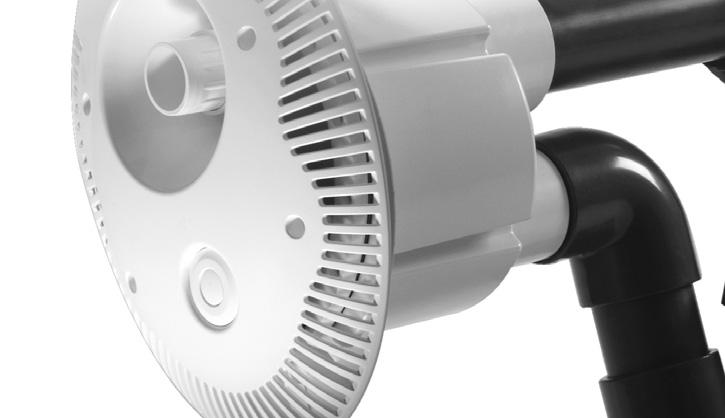
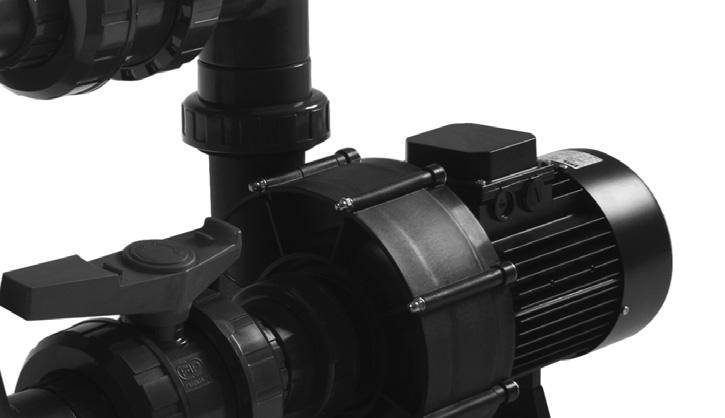
11 10. ELEGANCE jet swim pump The ELEGANCE jet swim is using the STP-2200 pump of the three-phase type adjusted on 230/400V with the electric input of 2,2kW. For size see the picture 10 power characteristic picture 11. Picture 10 Picture 11 11
12 Conditions of guarantee Conditions of guarantee abide by the trading and guarantee conditions of your supplier. Secure disposal of the product after the lifetime expiry After the lifetime expiry, ensure its ecologic disposal made by a skilled company Complaints and customer service Complaints abide by the appropriate consumer protection rights. In the event of unrecoverable effect address the written complaint to your supplier. Date... Supplier 12
COUNTER CURRENT UNIT. Instruction Manual
 COUNTER CURRENT UNIT Instruction Manual 1 Introduction: Congratulations on your purchase of a new Certikin counter current swimming unit. This unit has been developed and built by qualified personnel especially
INSTALLATION INSTRUCTIONS
 COUNTER-CURRENT SWIMMING Hurricane Turbo Swim Jet INSTALLATION INSTRUCTIONS PACKET NO.1 With a COUNTER-CURRENT SWIMMING device your swimming pool is no longer a simple man-made lake. It becomes the most
Operating Instructions
 Operating Instructions Light-metal Ex d enclosures / flameproof enclosure > 8265/0 Empty enclosure > 8265/4 Control panel, integrated in Ex e enclosure > 8265/5 Control panel Table of Contents 1 Table
Data sheet Pressure switch type CS December 2001 DKACT.PD.P10.A B1119
 Pressure switch type CS December 2001 DKACT.PD.P10.A2.02 520B1119 Introduction Pressure switch type CS is part of the Danfoss pressure control range. All CS pressure switches have a built-in pressure-operated,
Operating Instructions
 Operating Instructions Ex d Enclosures in Light Metal / Flameproof Encapsulation > 8265/0 Empty Enclosure > 8265/4 controller, installed in Ex e enclosure > 8265/5 controller Contents 1 Contents 1 Contents...2
Jet Swim Installation instruction
 Jet Swim 2000 Jet Swim 2000 Liner pool 1. Remove the stainless steel front plate and cut out the pool wall according to the hole pattern. The center of the Jet Swim housing must be a minimum of 170 mm
Pressure switches for air and water CS
 Data sheet Pressure switches for air and water CS CS pressure switches have a built-in pressure operated, three-pole switch. The contact position of which depends on the pressure in the connector and the
Poollift Delphin. Version: February, 2015 MANUAL AND OPERATING INSTRUCTIONS
 Poollift Delphin Version: February, 2015 MANUAL AND OPERATING INSTRUCTIONS Content 1. Introduction... 3 2. Technical Specifications... 3 Used materials... 3 3. Installation Instructions... 4 Fastening
Squeegee Unit for MRS Multi-Recovery System
 En Operating Instructions Squeegee Unit for MRS Multi-Recovery System Translation of the original operating instructions Squeegee - MRS Table of Contents Safety Recommendations Technical Data - MRS Booth
ELADOS EDP L Diaphragm Metering Pump Type
 ELADOS EDP L Diaphragm Metering Pump Type 04800-06700 Motor-driven diaphragm pump with integrated frequency converter High reserves due to a powerful asynchronous motor High flexibility due to variably
Parts Manual. Spray Gun Series Master III. Issue /11/2017 Ref. NR ENG
 Spray Gun Series Master III Issue 1.7 07/11/2017 Ref. NR-00072-ENG Before starting or doing maintenance on the MASTER III gun, carefully read all of the technical and safety documentation included in the
Blue Whale Spa :- Site Preparation and Delivery
 Pre-Delivery Instructions Please take the time to read this information carefully, as it will provide you with the information you will need to ensure the safe, secure, and timely installation of your
Translation of the original Operating Instructions for HKS rubber compensators
 Because of their flexible elements and mechanisms, HKS rubber compensators are susceptible to damage of all types and adverse loads in operation. For reliable operation of a compensator and, thus, the
Installation and Maintenance Manual. ECO Filtration Unit with 6-way-Top-Mount-Valve. Art. Nr
 Installation and Maintenance Manual ECO Filtration Unit with 6-way-Top-Mount-Valve Art. Nr. 300100 300101 300102 Important Details: - Using of this filtration unit for swimming pools and its guard band
USER MANUAL. JET TST and JET TST S.
 USER MANUAL JET TST and JET TST S www.sisteven.com Types of Jet fans: JET TST UNI: Impulse axial fan single direction JET TST S UNI: Impulse axial fan single direction (short case) JET TST REV: Impulse
Pneumatic proportional controller Types M Types FM Function tested for use of the float in Ex-zone 0
 Operating Manual LTIA5E Pneumatic proportional controller Types M Types FM Function tested for use of the float in Ex-zone 0 Contents 1. Safety Instructions 2. Conformity to standards 3. Technical data
10.2. Basketball Single Post System
 Basketball Basketball Single Post System The basketball single post is made from special aluminium profiles. The structure is supported by one post in the ground. The post measures a cross section of 120
PLEASE READ CAREFULLY BEFORE INSTALLING OR USING MEGA POOL SAVER MPS 1100
 MPS-1100 User Manual Mega Pool Saver Ltd PLEASE READ CAREFULLY BEFORE INSTALLING OR USING MEGA POOL SAVER MPS 1100 For further up to date instructions on how to install Mega Pool Saver MPS 1100, please
VPPL VARIABLE DISPLACEMENT AXIAL-PISTON PUMPS FOR INTERMEDIATE PRESSURE SERIES 10
 / ED VPPL VARIABLE DISPLACEMENT AXIAL-PISTON PUMPS FOR INTERMEDIATE PRESSURE SERIES OPERATING PRINCIPLE The VPPL are variable displacement axial-piston pumps with variable swash plate, suitable for applications
SPECIFICATIONS Type: Twin stack, single phase Tank: 4 gallon Air Output: PSI; PSI Max PSI: 125 PSI HP: 1.
 2 GALLON TWIN STACK AIR COMPRESSOR Model: 9526 DO NOT RETURN TO STORE. Please CALL 800-348-5004 for parts and service. CALIFORNIA PROPOSITION 65 WARNING: You can create dust when you cut, sand, drill or
PRO SINK -R 1 and 2. Dilution system CONTENTS
 PRO SINK -R 1 and 2 Dilution system CONTENTS 1.0 Product description 2 2.0 Warnings.. 3 3.0 Installation procedure 4 4.0 Plumbing connections 4 5.0 Technical features.. 5 6.0 Maintenance... 6 7.0 Troubleshooting......6
Model 405 &407 Small Animal Ventilator. User Manual v3.5
 Model 405 &407 Small Animal Ventilator User Manual v3.5 First of all, sincerely thanks for selecting the RWD405 or RWD407 small animal ventilator made by RWD company. Please read this instruction manual
Depth sensor. Product reference : REV 1. USER GUIDE and INSTALLATION GUIDE. nke Sailing competition
 Depth sensor Product reference : 90-60-456 REV 1 USER GUIDE and INSTALLATION GUIDE nke Sailing competition Z.I. Kerandré Rue Gutenberg 56700 HENNEBONT- FRANCE http://www.nke.fr After sale service n 33
OPERATING MANUAL. Contents. Bottom outlet ball valve Type ecoline
 OPERATING MANUAL Bottom outlet ball valve Type ecoline Contents 1 General Information 2 Safety 3 Packing, Handling, Storing 4 Product description 5 Preparation, Assembly 6 Commissioning 7 Handling 8 Attendance
Med Aire Alternating Pressure Pump and Pad System
 User Manual Med Aire Alternating Pressure Pump and Pad System 14002E 14001E Symbols & Statements NOTE Indicates some tips or some information users should be aware of. CAUTION Indicates correct operating
RLP100F901, F915, F924: Pneumatic room-pressure controller
 roduct data sheet 8. 7.40 RL00F90, F9, F94: neumatic room-pressure controller How energy efficiency is improved llows precise measurement and control of pressure differences in clean rooms or laboratories
Topline Peristaltic Dosing Pump for PAC Installation, Commissioning and O&M Manual
 Topline Peristaltic Dosing Pump for PAC Installation, Commissioning and O&M Manual Topline Electronics Limited 2105 This publication may not be copied, in full or in part, without prior written consent
PoolLock Easy Pool Cover
 PoolLock Easy Pool Cover INSTALLATION MANUAL The packaging of the PoolLock Easy Cover contains: 1. PoolLock Easy cover (rolled up) 2. One or two manual cranks (according to the pool size) Plastic bag contains:
Mounting and Operating Instructions EB 8546 EN. Supply Pressure Regulator Type Fig. 1 Supply pressure regulators
 Supply Pressure Regulator Type 4708 Type 4708-5352 on Type 3730 Positioner Type 4708-52 with filter receptacle Type 4708-6252 on Type 3372 ctuator Fig. Supply pressure regulators Mounting and Operating
Electropneumatic Positioner Type 4763 Pneumatic Positioner Type 4765
 Electropneumatic Positioner Type 4763 Pneumatic Positioner Type 4765 Application Single-acting positioner for attachment to pneumatic control valves. Supplied with either an electric input signal from
AIR COMPRESSOR OPERATION & MAINTENANCE INSTRUCTIONS MODEL NO: CHAMP 3 PART NO: LS0115
 AIR COMPRESSOR MODEL NO: CHAMP 3 PART NO: 2225222 OPERATION & MAINTENANCE INSTRUCTIONS LS0115 INTRODUCTION Thank you for purchasing this CLARKE Air Compressor. Please read this manual fully before use
11. Spare Parts. applications since applications since
 2 8 2 6 20 2 8 0 5 6 8 9 2 2 25 7 8 9 5 0 2 2 7 . Spare Parts * C0 C02 C06 C0 C7 C C0 C5 C58 Article No. Description B-26 B-2009 Steam generation Steam cylinder CY DN20 compl. with electrodes and hand
Y:\Machine Manuals & Spare Parts Lists\PARTS BREAKDOWN\Commercial CW Gas\HD850WS Page 1
 1.0 PIECE PARTS - parts listing 1 5311-0710 Nut 1 2 5443-2820 Hose Stem 1 3 6362-3950 O-Ring Seal 14.0x1.78 1 4 6414-2820 Strainer 1 5 6313-0030 Spring 2 6 5321-1980 Handhold 1 7 5066-2120 Cover 1 8 5363-1350
Siphon vessel / Priming aid
 Manufacturer: sera GmbH sera-straße 1 34376 Immenhausen Germany Tel.: +49 5673 999-00 Fax: +49 5673 999-01 info@sera-web.com Keep the operating manual for future use! Record the exact type and serial number
Dual fuel Gas-Oil/Gas burner
 Installation, use and maintenance instructions Dual fuel Gas-Oil/Gas burner MODEL GI/EMME 400 TYPE 496 T80 291 (6) TECHNICAL FEATURES Thermal power 116/232 465 kw - 100.000/200.000 400.000 kcal/h Fuels
QPEO2/037N Credit Value: 15 QCF Level: 2 GLH: 68 Maintaining electrical equipment/systems
 Performing Engineering Operations QPEO2/037N Credit Value: 15 QCF Level: 2 GLH: 68 Maintaining electrical equipment/systems Learner Name: 2013 Excellence, Achievement & Learning Ltd EAL Assessment Route
VERTICAL AIR COMPRESSORS
 VERTICAL AIR COMPRESSORS MODEL NO: VE15C150, VE18C150, VE25C150 PART NO: 2226010, 2226020, 2226025 OPERATION & MAINTENANCE INSTRUCTIONS LS0715 INTRODUCTION Thank you for purchasing this CLARKE Vertical
AIR COMPRESSOR MANUAL INSTALLATION, OPERATION AND MAINTENANCE GUIDE
 AIR COMPRESSOR MANUAL INSTALLATION, OPERATION AND MAINTENANCE GUIDE 1. DESCRIPTION The compressor is a reciprocating air pump mounted on and driven by an electric induction motor. Mounted on a sturdy frame
Medium Voltage Switchgear. Installation Manual for Pressure Relief Ducts
 Uniswitch Medium Voltage Switchgear Installation Manual for Pressure Relief Ducts TABLE OF CONTENTS 1 Summary... 1 2 Transportation and storage... 2 2.1 Condition on delivery... 2 2.2 Unpacking at installation
Inflatable Packer Single & Double. Single & Double Packer Dimension. Wireline Packer. Water Testing Packer (WTP) Packer
 Packer") Inflatable Packer Single & Double Single & Double Packer Dimension Wireline Packer Water Testing Packer (WTP) Packer Packer Working Pressure & Depth Chart Packer Water Hand Pump Packer Air Driven Pump
Inflatable Packer Single & Double Single & Double Packer Dimension Wireline Packer Water Testing Packer (WTP) Packer Packer Working Pressure & Depth Chart Packer Water Hand Pump Packer Air Driven Pump
INSTRUCTION MANUAL FOR MODEL 7360V VERTICAL CURING CHAMBER Revision E May
 INSTRUCTION MANUAL FOR MODEL 7360V VERTICAL CURING CHAMBER Revision E May 2015 98-0520 S/N 2001 N. Indianwood Ave. Tulsa, Oklahoma 74012 U.S.A. TEL: (918) 250-7200 FAX: (918) 459-0165 E-mail: chandler.sales@ametek.com
High Pressure Breathing Air Compressors
 High Pressure Breathing Air Compressors [ Full variety for different applications] MSA offers a comprehensive range of high pressure breathing air compressors for both the firefighting and diving market,
STYLE. Valid from 01/01/19 until 31/12/19 Sales prices in Euro excl. VAT.
 STYLE P R E F A B R I C A T E D S W I M M I N G P O O L S P R I C E L I S T 2 0 1 9 Valid from 01/01/19 until 31/12/19 Sales prices in Euro excl. VAT. www.rivierapool.com Two popular models: Modena and
OFFICINE OROBICHE S.p.A. 1/9
 OFFICINE OROBICHE S.p.A. 1/9 INSTRUCTIONS MANUAL FOR LEVEL SWITCHES SERIES 7000 mod. 7250 AND 7400 Electric 1. INSTRUMENT DESCRIPTION Series 7000 level switches have been designed for external lateral
CFSW. Hinges with built-in safety multiple switch
 CFSW. Hinges with built-in safety multiple switch ELESA Original design Elesa Standards Main dimensions Fitting Weight Code Description L B f ±0.2 f 1 ±0.2 H h 1 h 2 d 3 d 4 C [Nm]# g 426601 CFSW.110-6-2NO+2NC-C-A
Hydraulic Punch Drivers
 INSTRUCTION MANUAL 7804SB / 7806SB Quick Draw 7704SB / 7706SB Quick Draw Flex 7904SB / 7906SB Quick Draw 90 Quick Draw Hydraulic Punch Drivers Serial Codes AHJ, YZ, and ZA Read and understand all of the
2 GALLON TWIN STACK AIR COMPRESSOR W/ HOSE REEL
 2 GALLON TWIN STACK AIR COMPRESSOR W/ HOSE REEL Model: 52024 CALIFORNIA PROPOSITION 65 WARNING: You can create dust when you cut, sand, drill or grind materials such as wood, paint, metal, concrete, cement,
TECHNICAL DATA MAINTENANCE AIR COMPRESSOR MODEL G-1
 Dry 131h 1. DESCRIPTION The Viking Model G-1 Maintenance Air Compressor is an electric motor-driven, aircooled, single-stage, oil-less compressor. The unit is equipped with a check valve and provides a
IECEx Certificate of Conformity Annexe
 for Certificate No.: IECEx TSA 09.004X Issue No.: 1 Equipment description pertaining to Issue 0 of this Certificate: A range of electrical power distribution, control, protection and monitoring equipment
Product Manual B-Safety ClassicLine & PremiumLine Emergency Eyewash and Eye/Face Wash Equipment
 Product Manual B-Safety ClassicLine & PremiumLine Emergency Eyewash and Eye/Face Wash Equipment 1. Application Emergency eyewash and eye/face wash equipment are prescribed first aid installations for workplaces
TOOL BOX 033- HOSEREEL SERVICE / FAULT FINDING
 In SANS 10105 you will find the Minimum water pressure for both the hydrant and the hose reel. Which is 300KPA Manufacturing Standard SANS 543 1 Front & Back plates 2 Curved Plate 3 Waterway assembly 4
Installation, use and maintenance instructions. Gas burner (5)
") Installation, use and maintenance instructions Gas burner MODEL GAS 4 TYPE 516 T80 291 (5) TECHNICAL FEATURES Thermal output 180-470 kw 154.800-404.200 kcal/h Fuel Natural gas Pci 8-10 kwh/m 3 = 7000-8600
Installation, use and maintenance instructions Gas burner MODEL GAS 4 TYPE 516 T80 291 (5) TECHNICAL FEATURES Thermal output 180-470 kw 154.800-404.200 kcal/h Fuel Natural gas Pci 8-10 kwh/m 3 = 7000-8600
Customer Responsibilities
 Thank you for purchasing an Agilent instrument. To get you started and to assure a successful and timely installation, please refer to this specification or set of requirements. Correct site preparation
RC 195 Receiver-Controller
 Document No. 129-082 RC 195 Receiver-Controller Product Description The POWERS RC 195 Receiver-Controller is a pneumatic instrument that receives one, two or three pneumatic inputs. It produces a pneumatic
Armatures for analytical probes
 Armatures for analytical probes For many different types of installations and applications Large range of probe holders General purpose, water treatment, food & beverage, pharmaceutical applications Type
Type 4708 Supply Pressure Regulator
 Type 478 Pressure Regulator Application pressure regulator used to provide pneumatic measuring and control equipment with a constant air supply Set point ranges. to.6 bar ( to 4 psi) or. to 6 bar (8 to
Electropneumatic Positioner and Pneumatic Positioner Type 3760 JIS
 Electropneumatic Positioner and Pneumatic Positioner Type 3760 Application Single-acting positioners for direct attachment to pneumatic control valves. An electric standardized signal of 4 to 20 ma or
Drawn up by: / RK Revision: 01 Reviewed: Page: 1 of 23 HI-SR 540 USA. Operating instruction SR 540 Face Shield
 Page: 1 of 23 Operating instruction SR 540 Face Shield Page: 2 of 23 General information The SR 540 Face Shield can be used together with the SR 500 Powered Air-Purifying Respirator system of components
RP series Rotor Pumps
 ontact etails RP series Rotor Pumps Nomenclature Features Low noise Substantial reduction of the operation noise, by to db (comparison with aikin products), and improved sound quality are achieved by adopting
Installation and Maintenance Instruction Manual
 Installation and Maintenance Instruction Manual Bi-metal Thermometer Model A and E in a configuration - pursuant to ASME B40.200: ##=E#=### or ##=ERT#=### - pursuant to EN 13190: ###=A#=### or ##=ART#=###
Monitoring device NTS 30
 P R O D U C T I N F O R M A T I O N Electronic level- and temperature monitoring device Monitoring device NTS 30 Contents Description Description... 2 Operating... 3 Design and electrical data... 4 Circuit
E10 E10 E10 E10 E10 E10 E10 E10 E10 E10 E10 E10 E10 E10. Cable gland Series 8161/7, 8161/8. Installation Equipment and Accessories E10/1.
 > Explosion protection type "Increased safety" > Degree of protection IP68 > Ex e and Ex i versions > Integrated blind plug (accessory) for closing unused cable glands > Cable diameter ranges from 1 to
Electropneumatic Positioner and Pneumatic Positioner Type 3760 JIS
 Electropneumatic Positioner and Pneumatic Positioner Type 3760 Application Single-acting positioners for direct attachment to pneumatic control valves. Supplied with an electric input signal of 4 to 20
IP65 Air Differential Pressure Switch
 Page 1 of 5 PA-DPS-9x IP65 Air Differential Pressure Switch Features: Benefits: Close switching differential IP65 Housing Duct fixing kit included Switching point easily adjusted with scale in One screw
SF SERIES CNG COMPRESSOR MODEL HF-4MH. 4 Nm3/Hour Displacement OPERATION MANUAL
 SF SERIES CNG COMPRESSOR MODEL HF-4MH 4 Nm3/Hour Displacement OPERATION MANUAL 1 Content 1. General Description...3 2. Main technical parameters...3 3. Structural principle...4 3.1Main structure...4 3.2Compressor
CARTRIDGE FILTERS. Models: CF50, CF75, CF100, CF150,
 CARTRIDGE FILTERS Models: CF50, CF75, CF00, CF50, The installation of this product should be carried out by a qualified pool technician, following the installation instructions provided in this manual.
Budget Range Operators Handbook
 Budget Range Operators Handbook BAMBI AIR COMPRESSORS LTD 152 Thimble Mill Lane Heartlands Birmingham B7 5HT United Kingdom Tel: 0121 322 2299 Fax: 0121 322 2297 Email: sales@bambi-air.co.uk www.bambi-air.co.uk
24L OIL FREE AIR COMPRESSOR MODEL NO: TIGER 7/250 PART NO: OPERATION & MAINTENANCE INSTRUCTIONS LS10/13
 24L OIL FREE AIR COMPRESSOR MODEL NO: TIGER 7/250 PART NO: 2244030 OPERATION & MAINTENANCE INSTRUCTIONS LS10/13 INTRODUCTION Thank you for purchasing this product. Before attempting to use this product,
ARCHITECT INSTALLATION GUIDELINES FOR RESIDENTIAL TRITON INSTALLATIONS
 ARCHITECT INSTALLATION GUIDELINES FOR RESIDENTIAL TRITON INSTALLATIONS GENERAL LAYOUT Call SwimEx at 800-877-7946 to receive AutoCAD Drawings of the SwimEx Triton model that you will be installing. These
SCAM T.P.E. WATER TREATMENT SYSTEM SWT- AP AUTOMATIC PURGE
 SCAM T.P.E. WATER TREATMENT SYSTEM SWT- AP AUTOMATIC PURGE 1 TABLE OF CONTENTS 1. PURPOSE OF SUPPLY... 3 2. SYSTEM FUNCTIONING... 3 3. SYSTEM COMPONENTS... 4 4. BATTERY LIMITATIONS... 6 5. DOCUMENTATION...
Ground Fault Circuit Interrupter(GFCI) Policy
 Policy") NewStar Netronics, LLC American Products for the World Ground Fault Circuit Interrupter(GFCI) Policy 3926 East 3 rd Street Tulsa, OK 74112 Phone (918)894-5006 Fax (918)836-9909 tech@newstarnetronics.com
NewStar Netronics, LLC American Products for the World Ground Fault Circuit Interrupter(GFCI) Policy 3926 East 3 rd Street Tulsa, OK 74112 Phone (918)894-5006 Fax (918)836-9909 tech@newstarnetronics.com
SM6. instructions for use. connection with compartment for incoming cable from the top. MV distribution factory built assemblies at your service
 SM6 Anglais MV distribution factory built assemblies at your service instructions for use connection with compartment for incoming cable from the top foreword... 3 symbols and conventions... 3 as per iso
10.2. Basketball Single Post System
 Basketball Basketball Single Post System The single-post basketball stand is made with oval aluminium profiles with a cross-section of 120 x 100 mm. The wall thickness of this robust apparatus is 4 to
Pressure Dump Valve Service Kit for Series 3000 Units
 Instruction Sheet Pressure Dump Valve Service Kit for Series 000 Units. Overview The Nordson pressure dump valve is used to relieve hydraulic pressure instantly in Series 00, 400, 500, and 700 applicator
better measurement Simply a question of SCHMIDT Flow Sensor SS The cost-effective alternative in pressurised systems up to 10 bars.
 Simply a question of better measurement SCHMIDT Flow Sensor SS 20.261 The cost-effective alternative in pressurised systems up to 10 bars. Compressed air technology Industrial processes A cost analysis
Maintaining electrical equipment/systems
 Unit 037 Maintaining electrical equipment/systems Level: 2 Credit value: 15 NDAQ number: 500/9514/6 Unit aim This unit covers the skills and knowledge needed to prove the competences required to cover
Order No Projection Backboard
 Basketball Basketball Single Post System The single-post basketball stand is made with oval aluminium profiles with a cross-section of 120 x 100 mm. The wall thickness of this robust apparatus is 4 to
15000 Series Exhausting Arm - Wall Mount Models: 15076/15106/15146
 Operation and Maintenance Manual 15000 Series Exhausting Arm - Wall Mount Models: 15076/15106/15146 MONOXIVENT - SOURCE CAPTURE SYSTEMS - info@ Oct. - 2015 Receiving Assembly Information 15000 Series Exhausting
ATV 90 Y-12 YOUTH 2-STROKE RED (A2004ATB2BUSR) Page 1 of 52 A-ARM, FLOOR PANEL, AND BUMPER ASSEMBLY
 Page 1 of 52 A-ARM, FLOOR PANEL, AND BUMPER ASSEMBLY") 2004 ATV 90 Y-12 YOUTH 2-STROKE RED (A2004ATB2BUSR) Page 1 of 52 A-ARM, FLOOR PANEL, AND BUMPER ASSEMBLY 2004 ATV 90 Y-12 YOUTH 2-STROKE RED (A2004ATB2BUSR) Page 2 of 52 A-ARM, FLOOR PANEL, AND BUMPER
2004 ATV 90 Y-12 YOUTH 2-STROKE RED (A2004ATB2BUSR) Page 1 of 52 A-ARM, FLOOR PANEL, AND BUMPER ASSEMBLY 2004 ATV 90 Y-12 YOUTH 2-STROKE RED (A2004ATB2BUSR) Page 2 of 52 A-ARM, FLOOR PANEL, AND BUMPER
DIAPHRAGM PUMPS WITH KNF STABILIZATION SYSTEM
 DIAPHRAGM PUMPS WITH KNF STABILIZATION SYSTEM DATA SHEET E 037 N 940.5 APE as AC version in IP 54 N 940.5 APE-W with multi-voltage power supply input (As an option adjustable with potentiometer or by external
Electro-Pneumatic Converter YT-940 SERIES
 Electro-Pneumatic Converter YT-940 SERIES PRODUCT MANUAL VERSION 1.00 Contents 1. Introduction 3 1.1 General information for the users. 3 1.2 Manufacturer Warranty 3 1.3 Explosion Proof Warning. 4 2. Product
Pneumatic Oil Extractor
 Pneumatic Oil Extractor Operational Manual Model No.: JA1041OD 1 Safety Warnings and Precautions WARNING: When using tool, basic safety precautions should always be followed to reduce the risk of personal
Product information. Capacitive. Level detection in liquid VEGACAP 62 VEGACAP 63 VEGACAP 64 VEGACAP 66 VEGACAP 69. Document ID: 29983
 Product information Level detection in liquid VEGACAP 62 VEGACAP 63 VEGACAP 64 VEGACAP 66 VEGACAP 69 Document ID: 29983 Contents Contents 1 Description of the measuring principle... 3 2 Type overview...
LED 14W POLO BULKHEAD WITH MICROWAVE SENSOR
 INTRODUCTION The LED 14W POLO Bulkhead is a modern lowcost and energy efficient fitting ideal for domestic and utility applications. SPECIFICATION LED 1150lm IP54 220-240V IK09 4000K 50/ 60Hz >82 Ra 14W
Test and Adjustment Instructions Compressed Air Processing System Air Processing Unit (APU)
") Test and Adjustment Instructions Compressed Air Processing System Air Processing Unit () 1st issue 8150004983 815 000 498 3 This document is not covered by a revision service. New versions can be found
Test and Adjustment Instructions Compressed Air Processing System Air Processing Unit () 1st issue 8150004983 815 000 498 3 This document is not covered by a revision service. New versions can be found
SPG. Application example. Pneumatic 2-Finger Parallel Gripper Heavy-load Gripper. Weight 35 kg. Stroke per finger 100 mm.
 SPG Size 100 Weight 35 kg 10,000 N Stroke per finger 100 mm Workpiece weight 50 kg Application example Gripper unit for heavy V8 engine blocks. SPG 100 2-Finger Heavy-load Gripper 446 www.schunk.com SPG
AC1810 / AC1810-A TECHNICAL SPECIFICATIONS. Operating Pressure psi ( kgs/cm²) [AC1810] Displacement. Net Weight
![AC1810 / AC1810-A TECHNICAL SPECIFICATIONS. Operating Pressure psi ( kgs/cm²) [AC1810] Displacement. Net Weight](/thumbs/83/88369739.jpg "AC1810 / AC1810-A TECHNICAL SPECIFICATIONS. Operating Pressure psi ( kgs/cm²) [AC1810] Displacement. Net Weight") Technical Specifications Operating Instructions Maintenance Information Troubleshooting Guide Parts Diagrams AC1810 / AC1810-A THE EVOLUTION OF PERFECTION CAUTION: Before attempting to use or service this
Technical Specifications Operating Instructions Maintenance Information Troubleshooting Guide Parts Diagrams AC1810 / AC1810-A THE EVOLUTION OF PERFECTION CAUTION: Before attempting to use or service this
SLV4 Purge Air Unit MMMOPERATING INSTRUCTIONSMMMI. Installation, Operation, Maintenance
 SLV4 Purge Air Unit MMMOPERATING INSTRUCTIONSMMMI Installation, Operation, Maintenance Described Product Product name: SLV4 Variants: SLV4 2BH1300 SLV4 2BH1400 SLV4 2BH1500 Document ID Title: Operating
![[Graphic Division] 10](/thumbs/89/99951971.jpg "[Graphic Division] 10")
OPERATION MANUAL RTI RHS650 RTI TECHNOLOGIES, INC East Market Street York, PA Manual P/N
 OPERATION MANUAL RTI RHS650 RTI TECHNOLOGIES, INC. 4075 East Market Street York, PA 17402 Manual P/N 035-80589-02 Table of Contents Components... 2 Test... 4 Recovery/Recycling... 5 Evacuation... 7 Charging...
Air Differentail Pressure Switch
 Page 1 of 5 PA-DPS-8x Air Differentail Pressure Switch Features: Benefits: Close switching differential Duct fixing kit included Switching point easily adjusted with scale in Pascals Conduit entry can
Do not open during installation
 WE-EF LEUCHTEN Installation and Maintenance Instructions Inground Luminaire ETC310-FS LED EVC310-FS LED ETC319-FS LED EVC319-FS LED This product is factory-sealed. Do not open during installation Refer
Mounting and Operating Instructions EB 8546 EN. Type 4708 Supply Pressure Regulators. Translation of original instructions. Type Type
 Type 4708 Supply Pressure Regulators Translation of original instructions Type 4708-53 Type 4708-64 Type 4708-12 Mounting and Operating Instructions Edition March 2018 Note on these mounting and operating
BioAerosol Nebulizing Generator. Operation and Maintenance User Manual
 BioAerosol Nebulizing Generator Operation and Maintenance User Manual INTRODUCTION The BANG or BioAerosol Nebulizing Generator is a unique nebulizer for the generation of aqueous aerosols at a low air
Type 4708 Supply Pressure Regulator
 Type 478 Pressure Regulator Application pressure regulators used to provide pneumatic measuring and control equipment with a constant air supply Set point ranges. to. bar ( to 4 psi). to bar (8 to 9 psi)
Rules for Classification and Construction Additional Rules and Guidelines
 VI Rules for Classification and Construction Additional Rules and Guidelines 3 Machinery Installations 4 Guidelines for Equipment on Fire Fighting Ships Edition 2008 The following Guidelines come into
Gas Furnaces 95AF. Warranty Heat Exchanger - 20 Year Limited Parts - 5 Year Limited. 95% AFUE 44,000 to 110,000 Btuh Input 2 to 5 Tons Add-On Cooling
 PRODUCT SPECIFICATIONS INSTALLATION OPTIONS Available in Upflow/Horizontal and Counterflow models HEAT EXCHANGER Aluminized steel tapered design primary heat exchanger with crimped construction for long
UsER manual for Watersens ph -REDOX
 UsER manual for Watersens -REDOX Cl 8 1 2 6 3 3 7 7 4 4 4 4 Parts List 1 Redox Probe 1 x 2 PH Probe 1 x 5 Tube Weight 2 x 6 Connection Valve 1 x chlorine 3 Chlorine and Pumps 2 x 7 Dosing Valve 2 x 5 5
OWNER S TECHNICAL MANUAL
 EL SERIES OWNER S TECHNICAL MANUAL DP7002 1 Air Operated Diaphragm Pump Description The DP7002 1 air operated diaphragm pump is the ideal device for the pumping, transfer and dispensing of chemical liquids,
Methylethycetone (MEC) - PMS 60 polyurethane glue - Grease - White silicone
 - PMS 60 polyurethane glue - Grease - White silicone") CHAPTER PLAN page : 1/8 SAILING BOAT SUSPENDED WITHOUT DECK BEARING SAILING BOAT SUSPENDED WITH DECK BEARING SAILING BOAT SUSPENDED WITH AUTOMATIC BEARING ALIGNMENT RUDDER SYSTEM FOR ANTARES MOTOR BOAT
CHAPTER PLAN page : 1/8 SAILING BOAT SUSPENDED WITHOUT DECK BEARING SAILING BOAT SUSPENDED WITH DECK BEARING SAILING BOAT SUSPENDED WITH AUTOMATIC BEARING ALIGNMENT RUDDER SYSTEM FOR ANTARES MOTOR BOAT