John Sushko. Major Professor: Kyle B. Reed, Ph.D. Rajiv Dubey, Ph.D. Jose Porteiro, Ph.D. Date of Approval: October 21, 2011
|
|
|
- Angelica Jennings
- 6 years ago
- Views:
Transcription
1 Asymmetric Passive Dynamic Walker Used to Examine Gait Rehabilitation Methods by John Sushko A thesis submitted in partial fulfillment of the requirements for the degree of Master of Science Department of Mechanical Engineering College of Engineering University of South Florida Major Professor: Kyle B. Reed, Ph.D. Rajiv Dubey, Ph.D. Jose Porteiro, Ph.D. Date of Approval: October 21, 2011 Keywords: model, simulation, prosthesis, PDW, transfemoral Copyright c 2011, John Sushko
2 Dedication This thesis is dedicated to my mother for her never ending support.
3 Acknowledgments To my advisor Dr. Kyle B. Reed for his knowledge in programming and passive dynamics. To Craig Honeycutt for his help on this project. To Ismet Handzic for his help and encouragement. To my girlfriend Brittany Wingo for her support and understanding of all the long nights in the lab.
4 Table of Contents List of Tables List of Figures Abstract iii iv vii Chapter 1: Introduction to Research 1 Chapter 2: Background Passive Dynamic Walker Models Passive Dynamic Walkers The Gait Dynamics of a Passive Dynamic Walker Model Application For Rehabilitation 12 Chapter 3: Nine Mass Kneed Walker Model Three-Link and Two-Link Dynamics The Three-Link Phase Dynamics The Two-Link Phase Dynamics Collision Events Knee Strike Heel Strike Nine Mass Model Results Creating a Large Asymmetry by Changing the Moment of Inertia While Keeping the Center of Mass Constant Correcting the Large Asymmetries that Arose Trends of Changing Moment of Inertia on a Passive Dynamic Walker Model 32 Chapter 4: Model Uses Correcting a Longer Leg s Asymmetry by Adding Mass Anthropomorphic Model Prosthetic Model Prosthetic Model Results Physical Walker 53 i
5 Chapter 5: Conclusions and Future Work Conclusions Future Work Joint Torques Spasticity Human Validation 62 List of References 63 Appendices 66 Appendix A: Five Mass Model Derivation 67 ii
6 List of Tables Table 4.1 Anthropomorphic Model Mass 50 Table 4.2 Anthropomorphic Model Mass Locations 50 Table 4.3 Prosthesis Model Mass Results 53 Table 4.4 Prosthesis Model Knee Location Results 53 iii
7 List of Figures Figure 2.1 The rimless wheel 5 Figure 2.2 This shows evolution of the walker models 6 Figure 2.3 Some previous work on passive dynamic walkers 7 Figure 2.4 The symmetric step pattern 10 Figure 2.5 The single step pattern 10 Figure 2.6 The double step pattern 11 Figure 2.7 The quadruple step pattern 11 Figure 2.8 The gait enhancing mobile shoe (GEMS) 13 Figure 3.1 The nine mass model 15 Figure 3.2 The nine mass three link model 17 Figure 3.3 The nine mass two link model 17 Figure 3.4 The masses on the right leg shank are separated by 0.24m 28 Figure 3.5 The masses on the right leg thigh separated by 0.25m 29 Figure 3.6 The masses on both the shank and thigh right leg are separated by 0.07m and 0.26m 30 Figure 3.7 The symmetric solution when the shank masses on the right leg are separated by 0.24m 33 Figure 3.8 The symmetric solution when the thigh masses on the right leg are separated by 0.25m 34 iv
8 Figure 3.9 The symmetric solution when the thigh masses on both the shank and thigh right leg are separated by 0.07m and 0.26m 35 Figure 3.10 The step length changing with different parameters when b1r = 0.24m 37 Figure 3.11 The step length changing with different parameters when b2r = 0.25m 38 Figure 3.12 The step length changing with different parameters when b1r = 0.07m and b2r = 0.26m 39 Figure 4.1 The plot of mt2l versus step length 41 Figure 4.2 This plot shows the gait dynamics when the right leg is 1.02m long 43 Figure 4.3 The symmetric solution when the right leg is 1.02m 44 Figure 4.4 The configuration with the largest asymmetry when the right leg is 1.02m 44 Figure 4.5 These plots show the gait dynamics when the right leg is 1.05m long 46 Figure 4.6 The symmetric solution when the right leg is 1.05m 47 Figure 4.7 The configuration with the largest asymmetry when the right leg is 1.05m 47 Figure 4.8 The anthropomorphic model 49 Figure 4.9 The prosthesis model 52 Figure 4.10 The prosthesis symmetric gait pattern when the mass is heavier than the intact leg 54 Figure 4.11 The prosthesis symmetric gait pattern when the mass is lighter than the intact leg 55 Figure 4.12 The prosthesis asymmetric gait pattern when the mass is lighter than the intact leg 56 v
9 Figure 4.13 The picture of the physical walker 57 Figure 4.14 The Solid Works drawing the physical walker 58 vi
10 Abstract Testing gait rehabilitation devices on humans can be a difficult task, due to the effects of the neurological controls of the human body. This thesis advances the use of a passive dynamic walker (PDW) tuned to have asymmetric gait patterns similar to those with physical impairments to test rehabilitation devices. A passive dynamic walker is a multipendulum system that has a stable gait pattern when walking down a slope without any energy inputs except the forces due to gravity. A PDW model is better suited for testing rehabilitation devices because it has been shown to resemble human gait and separates the human neurological controls from the purely dynamic aspects of walking. This research uses different asymmetric gait patterns based on an asymmetric PDW to aid in the design of current and future rehabilitation methods. There are four major parts to this research: (1) the derivation of the current nine mass PDW model, (2) the effects of changing the moment of inertia and center of mass on each leg, (3) the effects of having a leg that is longer than the other and adding masses on the opposite leg to generate a symmetric gait, and (4) the design of a theoretical prosthesis that will break the assumption that the knee on the prosthetic leg should be in the same location as the intact leg. The result of changing the moment of inertia and center of mass on each leg in the nine mass model showed that it is an improvement over the previously used five mass model. This is because the five mass model forces the center of mass to change with the moment of inertia, while the nine mass model allows these to be changed independently of each other. A theoretical prosthesis has been developed in this research that is is significantly lighter vii
11 while maintaining a symmetric gait. This was accomplished by moving the knee of the prosthetic limb below the location of the intact knee. viii
12 Chapter 1: Introduction to Research This thesis shows the use of a passive dynamic walker (PDW) for testing rehabilitation methods and devices. A PDW is a multi-link pendulum system that exhibits a steady and stable gait when walking down a slope without any energy inputs except the forces due to gravity. This research uses PDW models because they have shown their ability to recreate a gait that is repeatable and is dynamically similar to humans [15]. The dynamics of a PDW model can be modified to produce asymmetric gait patterns that are similar to individuals with impairments. These asymmetries will be used to examine gait rehabilitation methods. A PDW is important for this purpose because it separates the mechanical aspects of walking from the neurological controls of a human. The ability to separate the neurological controls from walking is what will aid in the design and testing of rehabilitation devices. Testing gait rehabilitation devices on humans is problematic due to the cognitive influences that emerge while walking. A large part of this research is the derivation of the nine mass PDW model and how it is an improvement over previous models. To validate this model, I explored the effects of changing the center of mass and moment of inertia of each leg. This validation focuses on the rotational inertia and center of mass of each link and relates it to the symmetry of the walker model by changing the locations of the masses on the PDW model. I also performed tests on the nine mass model to analyze different rehabilitation methods. These tests were designed to reduce the asymmetries arising from common impairments. The first test looked at correcting the asymmetry that arises when an individual has one leg that is longer than the other. This asymmetry was reduced by adding two masses on the 1
13 shorter leg. The second test was to reduce the asymmetry that transfemoral amputees experience while wearing their prostheses. This is achieved by moving the prosthetic knee location below the intact knee location and reducing the prosthetic mass. The application of passive dynamic walkers being used for gait rehabilitation is a generally novel idea. Until now, there has not been research that links PDWs with human gait correction. The only research that has been conducted that uses non-human models for gait rehabilitation was done by Otoda. Otoda used a learning algorithm on a humanoid robot walking on a split-belt treadmill [16]. A split-belt treadmill has two belts that can move independently of each other at different speeds. It has been shown that walking on a split-belt treadmill can be used to correct gait impairments (explained in more detail later in this thesis) [18]. Otoda found that the robot was able to adapt its gait to the motion of the treadmill by changing parameters on its body [16]. One of the problems with humanoid robots is that they are very complex so the number of variables greatly increases. Also, the study of non-human gait asymmetries is rather new. Gregg et al. focused on biped asymmetries arising from changing physiological or environmental conditions on the biped [8]. Examples of some of these changing conditions are the ramp angle and the initial angular positions and velocities. My research of using a passive dynamic walker to study gait dynamics for rehabilitation methods is original. Another important reason for this research is all prior research used the five mass model (explained in detail later in this thesis). I have extended this to a nine mass model by adding an extra mass on each individual link of the walker, four in total. My hypothesis is that adding the four more masses will better describe the mass distribution of physical legs. This is because I can tune the moment of inertia to be similar to that of a human. I think that having these extra masses will better aid in the tuning of physical passive dynamic walkers. The five mass model forces the moment of inertia to change when the center of mass is changed, which is not ideal for tuning. With the nine mass model I can 2
14 change the moment of inertia independent of the center of mass. Tuning a PDW with the moment of inertia of the leg links is of greater importance than the location of the center of mass. This model is currently being used for designing and tuning the physical PDW in [10]. The ability to change the moment of inertia while keeping the center of mass constant expedited the tuning phase of the walker. This is because it can be used for cause and effect scenarios. For example, the model can be used to test new design configurations on the walker before actually being applied to the physical walker. The physical PDW is detailed in [10] and discussed some later in this thesis. 3
15 Chapter 2: Background This thesis presents the derivation and application of a mathematical model of a two dimensional planar walker. The model is based upon the principles of passive dynamic walking and will be implemented to test gait rehabilitation techniques. This chapter will discuss the history of passive dynamics, the previous walker models, gait dynamics of the models, and how it can be used for rehabilitation. 2.1 Passive Dynamic Walker Models "A passive dynamic walker (PDW) is a device that exhibits a steady and stable gait down a slope without any energy inputs except the forces due to gravity" [11]. The dynamics of a passive dynamic walker approximate the gait dynamics of a human accurately [15]. An important part of the study of passive dynamic walkers is the mathematical models that describe the walker s dynamics. The first theoretical model that describes gait dynamics and locomotion was created by Margaria in Margaria stated that human gait dynamics are similar to that of a rimless wheel rolling down a hill. The rimless wheel shown in Figure 2.1 has massless spokes and a single point mass at the center. The rimless wheel eventually settles into an equilibrium [13]. McGeer used the rimless wheel dynamics to derive equations that describe the first PDW model. McGeer noticed that the equilibrium that a PDW settles into is similar to the equilibrium that the rimless wheel exhibits [15]. Out of McGeer s research came the compass gait model. This model relates walking to passive dynamics in the simplest form [6]. The compass gait model is a double pendulum 4
16 Figure 2.1: The rimless wheel system with two leg masses and a hip mass, which follows human like gait patterns [7]. The compass gait model is shown in Figure 2.2a. In 2005, Chen advanced the compass gait model by adding knees and two more masses, as shown in Figure 2.2b. Chen created a full mathematical model for this system similar to the equations derived for the compass gait [1]. I then extended Chen s research by differentiating between the left and right leg. This is the five mass model which lets us change specific parameters on each leg to find asymmetric gait patterns. The five mass model can be seen in Figure 2.2c. Figure 2.2c shows that the right leg (green) is different from the left leg (blue). Figure 2.2 shows a flow chart that depicts the evolution of the walker models starting with the compass gait [7], then Chen s kneed model [1], the five mass model [11], and finally the nine mass model. 2.2 Passive Dynamic Walkers Some of the walkers that have been previously designed and made can be seen in Figure 2.3. Starting on the left is McGeer s walker, that he designed in the 1980 s [15]. McGeer s 5
17 b mh mh mt b2 a q2 m q1 a1 b1 q3 ms mt q2 q1 ms a2 (a) Compass Gait (b) Chen Model mh mtr b1r q2 a1r q3 msl q1 b2l a2l c1r b1r a1r mh mt1r a2l mt2r b2l c2l q2 q1 q3 ms1l ms2l Right Leg Left Leg (c) Five Mass Model Right Leg Left Leg (d) Nine Mass Model Figure 2.2: This shows evolution of the walker models. Starting with the compass gait [7], Chen s kneed model [1], the five mass model [11], and the nine mass model. 6
![Figure 2.3: Some previous work on passive dynamic walkers. Left to Right: McGeer s first walker [15]; The Cornell biped with arms [3]; The Cornell Ranger [12]; The TU Delft MIKE Robot [21].](/docs-images/80/80917956/images/18-0.jpg "first walker was very interesting because it did not have knees but instead used motors to lift up the feet to clear the ground on each step.")
![McGeer mentions in his paper that to have the feet clear the ground one of the following techniques has to be employed: his ankle actuation, a walker that waddles from left to right, or knees [15].](/docs-images/80/80917956/images/18-1.jpg "Second from the left is the Cornell biped with arms [3]. This biped best describes the human gait. Due to its swinging arms it better represents the human trunk.")
18 Figure 2.3: Some previous work on passive dynamic walkers. Left to Right: McGeer s first walker [15]; The Cornell biped with arms [3]; The Cornell Ranger [12]; The TU Delft MIKE Robot [21]. first walker was very interesting because it did not have knees but instead used motors to lift up the feet to clear the ground on each step. McGeer mentions in his paper that to have the feet clear the ground one of the following techniques has to be employed: his ankle actuation, a walker that waddles from left to right, or knees [15]. Second from the left is the Cornell biped with arms [3]. This biped best describes the human gait. Due to its swinging arms it better represents the human trunk. Third from the left is the Cornell ranger which holds the record for longest distance traveled by a PDW of 40.5 miles. The Ranger has actuators on the ankles to add in the energy at heel-strike [12]. The walker farthest on the right is the Tu Delft MIKE robot. It is an autonomous walking robot based on a PDW. The MIKE robot has minimal amounts of actuation at the knees and foot to add energy into the system. The actuators are pneumatic and have to be very light and efficient to add the needed amount of energy but light enough to not affect the dynamics. The actuators essentially act as muscles for the robot [21]. 7
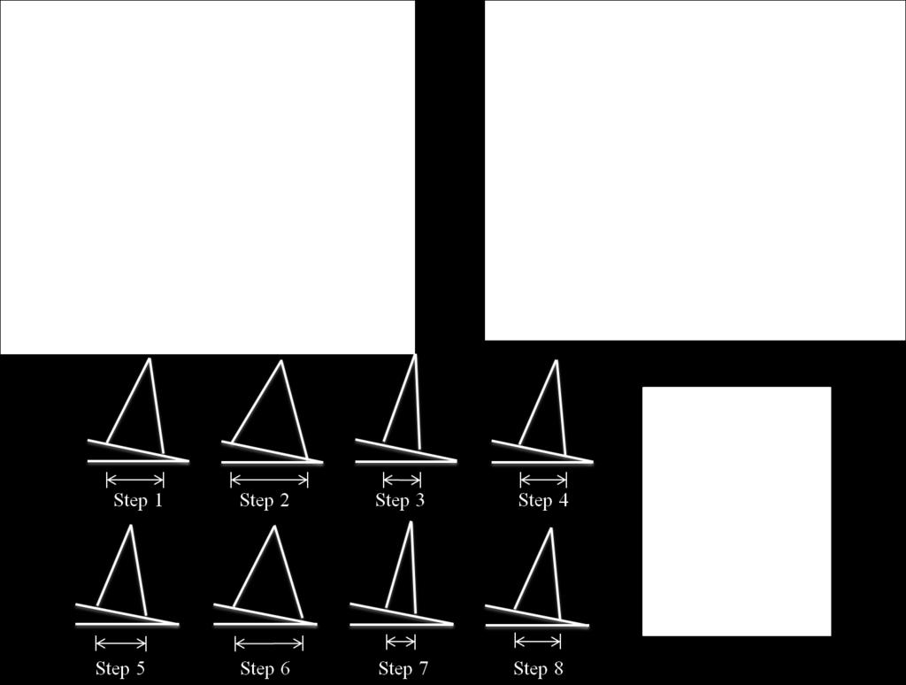
19 2.3 The Gait Dynamics of a Passive Dynamic Walker Model In preliminary research for this thesis, one dimensional tests were used to evaluate the effects of changing the magnitude of the link masses, the location of the the link masses and the position of the knee [11]. This research evaluated the previously mentioned five mass model. The five mass model can be seen in Figure 2.2c. Parameters were changed on the right leg of the five mass model to alter its gait pattern from symmetry. Specific parameters were changed to create different model configurations. Asymmetries arose from some of these configurations. For a model configuration to be a successful configuration, it had to walk for fifty steps. The asymmetries are defined by having step lengths of the left and right leg that are not equal. Step length is the distance between the legs when the swing leg makes contact with the ground. After changing the parameters, four different gait patterns emerged: 1. Symmetric step pattern: This pattern is normal symmetric walking where both step lengths quickly converge to one value. This gait pattern best represents human gait, as seen in Figure The leg specific single step pattern: For this pattern, each leg has its own specific step length. This is the most stable step pattern besides the symmetric pattern. This pattern best represents an asymmetric gait pattern of a human who has suffered a stroke or other impairments. An example of the single step pattern can be seen in Figure Leg specific double step pattern: Whereas in the single step pattern each leg has its own step length, in the double step pattern each leg has two unique step lengths. Looking at Figure 2.6, the right leg always has a longer step length than the left leg. Step 2 corresponds to the first right leg step in the cycle. This occurs when the right leg is swinging. Figure 2.6 also shows that step 2 is always the longest. 8
20 4. Leg specific quadruple step pattern: This is the most interesting gait pattern produced in [11]. Similar to the double step, step 2 will always have the longest step length. There are now four specific step lengths for each leg. The gait pattern can be seen in Figure 2.7. These gait patterns were a study of interesting dynamics and gives a basis on the dynamics of walking. The single step pattern will be useful for modeling gait patterns of humans with impairments, but the research done in [11] does not take any major steps toward rehabilitation. That being said, it did give insight into the effects of changing different design parameters. The research done in [11] produced useful descriptions of the symmetry on a PDW model configuration. The top of Figures 2.4 through 2.7 show two different plots. The plot on the left is the step length plot, which compares the step length versus the step number, and is the main measuring tool for symmetry. On the right is the limit cycle trajectory, which depicts the motion in each phase of of the PDW s gait. The limit cycle plot shows the angle in radians versus angular velocity in radians per second. Figure 2.5 describes the limit cycle plot and what each color line depicts. This plot follows the right leg in every part of its dynamics. This plot directly relates to the kinetic and potential energy of the right leg. Red and green are the three-link and twolink phases while the right leg is swinging. There is a jump between the red and green lines that shows the energy change after knee strike. After the green line, there is another jump that separates the blue line, which is the energy change from heel strike. The blue and black lines are the three-link and two link phases when the right leg is the stance leg. The jump between the back and blue lines is the energy changed due to knee strike of the left leg. The energy change between the black and red line is the heel strike event for the left leg. The cycle starts back with the red line where the right leg is swinging in threelink phase. These dynamics will be explained in better detail later in this thesis when the current PDW model is described. 9


21 Angular velocity Figure 2.4: The symmetric step pattern. Angular velocity Figure 2.5: The single step pattern. 10


22 Angular velocity Figure 2.6: The double step pattern. Angular velocity Figure 2.7: The quadruple step pattern. 11
23 2.4 Application For Rehabilitation As stated above, currently the only research being done that uses non-human models for gait rehabilitation uses humanoid robots. Humanoid robots were not chosen for this research because their gait does not model the gait of a human very accurately. The reason for this is because humanoid robots walk in a quasi-static manor, meaning that the way they achieve equilibrium is statically. So a humanoid robot can stop at any point in its gait. The most notable humanoid robot is the Honda AISMO, which demonstrates very clearly a non-human gait. Humans on the other hand walk in a dynamic equilibrium. There are points in a human s gait pattern where they cannot stop because they will fall. A human s gait can be described as perpetual free fall. A PDW has as similar gait pattern to a human because it can also only achieve equilibrium dynamically. This makes PDWs ideal to test rehabilitation methods and devices. PDWs allow the ability to examine different asymmetric gait patterns without the cognitive influence of human neurological controls. This is important when studying individuals with neurological disorders like someone who suffered a stroke and will aid in the design of rehabilitation devices. One of these devices I would like to examine is the Gait Enhancing Mobile Shoe (GEMS) [4][9]. The GEMS is a rehabilitation shoe that focuses on correcting human asymmetric gaits. The GEMS is shown in Figure 2.8. Studies have shown that the use of split-belt treadmill training can correct asymmetric gaits. A split-belt treadmill is a treadmill that has two treads that can each move at different speeds allowing for control of each of the participant s legs independently. This ability for control is what allows for the gait correction because it forces the lagging leg to walk at a faster rate, which exaggerates the asymmetry and generates an after-effect that is the correct gait. The effects of splitbelt treadmill rehabilitation diminish quickly when the participants start walking on solid ground [18][2]. It is not clearly known why these effects diminish so quickly. One major hypothesis is that the perception while walking on the treadmill differs greatly from walk- 12
![Figure 2.8: The gait enhancing mobile shoe (GEMS). [9] ing on solid ground.](/docs-images/80/80917956/images/24-0.jpg "The GEM shoe replicates the backwards motion that the split-belt treadmill produces, but allows the participant to walk on solid ground [9].")
24 Figure 2.8: The gait enhancing mobile shoe (GEMS). [9] ing on solid ground. The GEM shoe replicates the backwards motion that the split-belt treadmill produces, but allows the participant to walk on solid ground [9]. If the GEM shoe could be modeled mathematically, it could be imposed on one of the feet in the nine mass model to correct a theoretical asymmetric gait. The nine mass model could be applied to transfemoral prosthesis design. Individuals who wear a prostheses typically have an asymmetry where their prosthetic leg has a step length that is longer than their intact leg. Because of this asymmetry and the weight of the prosthesis, individuals with a prosthetic limb use more energy when walking than individuals with both legs intact [14]. Mattes et al. discuss that a symmetric gait pattern and weight reduction reduce the energy used while walking [14]. My model is used in this thesis to find a symmetric gait pattern for a prosthesis that is also significantly lighter. 13
25 Chapter 3: Nine Mass Kneed Walker Model A kneed passive dynamic walker can be modeled as a multi-pendulum system that is unactuated. The first iteration of the model was done by Chen [1], who took the compass gait model and added knees, thus making it a more human like model. I took this further in my model by differentiating between each leg. The two legs are the stance leg (st), which is the leg that is in contact with the ground, and the swing leg (sw), which is the leg swinging freely. Using swing and stance makes the equations more general. In practice the equations have to be written twice in terms of right and left leg changing from stance to swing. For example, one set of equations describe when the left leg is the stance leg and the other set would describe when the right leg is the stance leg. This differentiation is used to develop asymmetries by changing parameters on each leg. I call this model the five mass system and it is shown in Figure 2.2c. To better develop asymmetries, I added another mass on each link making a nine mass system. The nine mass model is seen in Figure 2.2d and in Figure 3.2. With this model, I can more accurately describe the leg mass distribution. The nine masses are the hip mass (mh), the upper shank mass on the stance leg (ms2 st ), the lower shank mass on the stance leg (ms1 st ), the upper thigh mass on the stance leg (mt1 st ), the lower thigh mass on the stance leg (mt2 st ), the upper shank mass on the swing leg (ms2 sw ), the lower shank mass on the swing leg (ms1 sw ), the upper thigh mass on the swing leg (mt1 sw ), and the lower thigh mass on the swing leg (mt2 sw ). The bottom rods are the shank links and the top rods are the thigh links. The shank length is ls = a1 + b1 + c1 and the thigh length is lt = a2 + b2 + c2, both in terms of st and sw. The total length is L = ls + lt, also in terms if st and sw. 14
26 mh a2r b2r mt2r mt1l a2l c2r mt1r mt2l b2l c1r q2 c2l a1r b1r q3 ms1r q1 c1l ms2r ms1l b1l ms2l a1l Right Leg Left Leg Figure 3.1: The nine mass model. 15
27 The nine mass system better approximates human legs and physical passive dynamic walker legs because I can better approximate the mass distribution. Also as stated previously, I am able to fine tune the moment of inertia to whatever model I am trying to examine. The nine mass model is an improvement over the five mass system because of the amount of adjustably and versatility it provides. The five mass model has also been derived, in Appendix A. The walker goes through two distinct stages in its dynamics: a two-link phase and a threelink phase. The three-link phase is the starting phase for the walker. The three-link phase is shown in Figure 3.2. From these figures it can be seen that L st is connected to the hip, which is in turn connected to lt sw. The knee is what joins ls sw to lt sw. The walker stays in the three-link phase until the knee strike event. After knee strike occurs, the knee is locked and the system is a double pendulum. This double pendulum system is the twolink phase shown in the nine mass model of Figure 3.3. The walker is in two-link phase until the heel strike event. Heel strike finishes the cycle of the walker and three-link starts again. The two-link phase has two links L st and L sw, which are connected together by the hip. 3.1 Three-Link and Two-Link Dynamics The walker s dynamics can be derived using the Lagrangian formulation for a multipendulum system shown in (3.1). The three matrices in this equation H, B, and G are the inertia, velocity, and gravity matrices respectively. The components of these matrices will be described in the following equations. H(q) q + B(q, q) q + G(q) = 0 (3.1) 16
28 mh c1r mt1r mt2r q2 a2l b2l c2l a1r b1r q3 ms1l q1 ms2l Right Leg Left Leg Figure 3.2: The nine mass three link model. c2l b2l a2l mh mt1r mt2r q1 q2 c1r ms1l ms2l b1r a1r Right Leg Left Leg Figure 3.3: The nine mass two link model. 17
29 3.1.1 The Three-Link Phase Dynamics The three-link dynamics were derived using the Lagrangian formulation for a pendulum system with multiple links. The three-link inertia matrix for a nine mass system is derived in the following equations: H11 = ms1 st a1 2 st + ms2 st (a1 st + b1 st ) 2 + mt2 st (ls st + c2 st ) 2 + mt1 st (ls st + c2 st + b2 st ) 2 + (3.2) (mh + ms1 sw + ms2 sw + mt1 sw + mt2 sw )L 2 st H12 = [mt1 sw a2 sw + mt2 sw (a2 sw + b2 sw )+ ms1 sw lt sw + ms2 sw lt sw ]L st cos(q 2 q 1 ) (3.3) H13 = [ms2 sw c1 sw + ms1 sw (c1 sw + b1 sw )]L st cos(q 3 q 1 ) (3.4) H21 = H12 (3.5) H22 = mt1 sw a2 2 sw + mt2 sw (a2 sw + b2 sw ) 2 + ms1 sw lt 2 sw + ms2 sw lt 2 sw (3.6) H23 = [ms2 sw c1 sw + ms1 sw (c1 sw + b1 sw )]lt sw cos(q 3 q 2 ) (3.7) H31 = H13 (3.8) H32 = H23 (3.9) H33 = ms2 sw c1 2 sw + ms1 sw (c1 sw + b1 sw ) 2 (3.10) H11 H12 H13 H = H21 H22 H23 (3.11) H31 H32 H33 18
30 The three-link velocity matrix for the 9 mass system is derived in the following equations: h122 = [mt1 sw a2 sw + mt2 sw a2 sw + b2 sw )+ ms1 sw lt sw + ms2 sw lt sw ]L st sin(q 2 q 1 ) (3.12) h133 = [ms2 sw c1 sw + ms1 sw (c1 sw + b1 sw )]L st sin(q 3 q 1 ) (3.13) h211 = h122 (3.14) h233 = [ms2 sw c1 sw + ms1 sw (c1 sw + b1 sw )]lt sw sin(q 3 q 2 ) (3.15) h311 = h133 (3.16) B = h322 = h233 (3.17) 0 h122 q 2 h133 q 3 h211 q 2 0 h233 q 3 (3.18) h311 q 1 h322 q 2 0 The gravity matrix for the 9 mass system in the three-link phase is derived in the following equations: g 1 = [ms1 st a1 st + ms2 st (a1 st + b1 st )+ mt2 st (ls st + c2 st ) + mt1 st (ls st + a2 st + b2 st )+ (3.19) (mh + ms1 sw + ms2 sw + mt1 sw + mt2 sw )L sw ] sin(q 1 )g g 2 = [mt1 sw a2 sw + mt2 sw (a2 sw + b2 sw )+ ms1 sw lt sw + ms1 sw lt sw ] sin(q 2 )g (3.20) g 3 = [ms2 sw c1 sw + ms1 sw (b1 sw + c1 sw )] sin(q 3 )g (3.21) G = [g 1 g 2 g 3 ] T (3.22) 19
31 3.1.2 The Two-Link Phase Dynamics The two-link phase equations are similar to the three-link except less complicated. Due to the fact that the knee is locked for the two-link phase the amount of terms are reduced. The two-link inertia matrix is derived in the following equations: H11 = ms1 st a1 2 st + ms2 st (a1 st + b1 st ) 2 + mt2 st (ls st + c2 st ) 2 + mt1 st (ls st + c2 st + a2 st ) 2 + (3.23) (mh + ms1 sw + ms2 sw + mt1 sw + mt2 sw )L 2 st H12 = [mt1 sw a2 sw + mt1 sw (a2 sw + b2 sw ) + ms2 sw (lt sw + c1 sw )+ ms1 sw (lt sw + b1 sw + c1 sw )]L st cos(q 2 q 1 ) (3.24) H22 = mt1 sw a2 2 sw + mt2 sw (a2 sw + b2 sw ) 2 + H21 = H12 (3.25) ms2 sw (lt sw + c1 sw ) 2 + ms1 sw (lt sw + c1 sw + b1 sw ) H = H11 H21 H12 H22 The Lagrangian velocity matrix for the two-link phase: (3.26) (3.27) h = [mt1 sw a2 sw + mt2 sw (a2 sw + b2 sw ) + ms2 sw (lt sw + c1 sw )+ ms1 sw (lt sw + b1 sw + c1 sw )]L st sin(q 2 q 1 ) (3.28) B = 0 h q 2 h q 1 0 (3.29) 20
32 g 1 = [ms1 st a1 st + ms2 st (a1 st + b1 st )+ mt2 st (ls st + c2 st ) + mt1 st (ls st + a2 st + c2 st )+ (3.30) (mh + ms1 sw + ms2 sw + mt1 sw + mt2 sw )L sw ] sin(q 1 )g g 2 = [mt1 sw a2 sw + mt2 sw (a2 sw + b2 sw )+ ms2 sw (lt sw + c1 sw ) + ms1 sw (lt sw + b1 sw + c1 sw )] sin(q 2 )g G = g 1 g 2 (3.31) (3.32) 3.2 Collision Events The collision events, as mentioned earlier, are the knee strike and heel strike. These collisions are modeled as inelastic and instantaneous. They are derived from the conservation of angular momentum about the appropriate point for the specific collision Knee Strike The knee strike collision is the collision that changes the walker from the three-link phase to the two-link phase. The collision is considered inelastic due to the fact that the knee stays locked through the two-link phase. The following equations take the pre-collision velocities (q ) and apply conservation of angular momentum and output the post-collision velocities (q + ). It is to be noted that the superscript + is post-collision and is pre-collision. q q 2 = Q q 1 q 2 q 3 Q (3.33)
33 α = q 1 q 2 (3.34) β = q 1 q 3 (3.35) γ = q 2 q 3 (3.36) Q + 11 = Q mt2 st (ls st + c2 st ) 2 + mt1 st (ls st + b2 st + c2 st ) 2 + (mh + mt1 st + mt2 st + ms1 st + ms2 st )L 2 st+ (3.37) ms1 st a1 2 st + ms2 st (a1 st + b1 st ) 2 Q + 12 = Q ms2 sw (lt sw + c1 sw ) 2 + ms1 sw (lt sw + b1 sw + c1 sw ) 2 + mt1 sw a2 2 sw + mt2 sw (a2 sw + b2 sw ) 2 (3.38) Q + 21 = [ms2 sw (c1 sw + lt sw ) + ms1 sw (c1 sw + b1 sw + lt sw ) mt1 sw a2 sw + mt2 sw (a2 sw + b2 sw )]L st cos(α) (3.39) Q + 22 = ms2 sw (lt sw + c1 sw ) 2 + ms1 sw (lt sw + b1 sw + c1 sw ) 2 mt1 sw a2 2 sw + mt2 sw (a2 sw + b2 sw ) 2 (3.40) Q 11 = [ms1 sw lt sw + ms2 sw lt sw + mt1 sw a2 sw mt2 sw (a2 sw + b2 sw )]L st cos(α) [ms2 sw c1 sw + ms2 sw (b1 sw + c1 sw )]L st cos(β)+ [ms1 sw + ms2 sw + mt1 sw + mt2 sw ]L 2 st+ (3.41) ms1 st a1 2 st + ms2 sw (a1 sw + b1 sw ) 2 + mt2 st (ls st + c2 st ) + mt1 st (ls st + b2 st + c2 st ) 22
34 Q 12 = [ms1 sw lt sw + ms2 sw lt sw + mt1 sw a2 sw + mt2 sw (a2 sw + b2 sw )]L st cos(α)+ [ms2 sw c1 sw + ms1 sw (b1 sw + c1 sw )]lt sw cos(γ)+ (3.42) mt1 sw a2 2 sw + mt2 sw (a2 sw + b2 sw ) 2 + ms1 sw lt 2 sw + ms2 sw lt 2 sw Q 13 = [ms2 sw c1 sw + ms2 sw (b1 sw + c1 sw )]L st cos(β)+ [ms2 sw c1 sw + ms1 sw (b1 sw + c1 sw )]lt sw cos(γ)+ (3.43) ms2 sw c1 2 sw + ms1 sw (b1 sw + c1 sw ) 2 Q 21 = [ms1 sw lt sw + ms2 sw lt sw + mt1 sw a2 sw + mt2 sw (a2 sw + b2 sw )]L st cos(α)+ (3.44) [ms2 sw c1 sw + ms2 sw (b1 sw + c1 sw )]L st cos(β) Q 22 = [ms2 sw c1 sw + ms1 sw (b1 sw + c1 sw )]lt sw cos(γ)+ mt1 sw a2 2 sw + mt2 sw (a2 sw + b2 sw ) 2 + (3.45) ms1 sw lt 2 sw + ms2 sw lt 2 sw Q 23 = [ms2 sw c1 sw + ms1 sw (b1 sw + c1 sw )]lt sw cos(γ)+ ms2 sw c1 2 sw + ms1 sw (b1 sw + c1 sw ) 2 (3.46) Q + = Q = Q+ 11 Q + 12 Q + 12 Q + 22 Q 11 Q 12 Q 13 Q 12 Q 22 Q 23 (3.47) (3.48) 23
35 3.2.2 Heel Strike The heel strike event is when the walker finishes the two-link phase by the swing foot impacting with the ground. After the impact the swing foot then becomes the stance foot and the walker starts the three-link phase and rotates around the new stance foot. + q 1 + q 2 + q 3 q + = q 2 q 1 q 1 = Q+ 1 q 1 q 2 (3.49) Q (3.50) q + 3 = q + 2 (3.51) α = q 1 q 2 (3.52) Q + 11 = Q ms1 sw a1 2 sw + ms2 sw (a1 sw + b1 sw ) 2 + mt1 sw (c2 sw + b2 sw + ls sw ) + mt2 sw (c2 sw + ls sw ) 2 + (3.53) (ms1 st + ms2 st + mt1 st + mt2 st )L 2 sw Q + 12 = Q ms2 st (c1 st + lt st ) 2 + ms1 st (c1 st + b1 st + lt st )+ mt1 st a2 2 st + mt2 st (a2 st + b2 st ) 2 (3.54) Q + 21 = [ms1 st (c1 st + b1 st + lt st ) + ms2 st (c1 st + lt st )+ mt1 st a2 st + mt2 st (a2 st + b2 st )]L sw cos(α) (3.55) Q + 22 = mt1 st a2 2 st + mt2 st (a2 st + b2 st ) 2 + ms2 st (lt st + c1 st ) 2 + ms1 st (lt st + b1 st + c1 st ) 2 (3.56) 24
36 Q 11 = Q 12 + [mhl st + 2mt2 st (c2 + ls st )+ 2mt1 st (c2 st + b2 st + ls st )+ (3.57) ms1 st a1 st + ms2 st (a1 st + b1 st )]L st cos(α) Q 12 = [ms1 sw a1 sw (lt sw + b1 sw + c1 sw )+ ms2 sw (a1 sw + b1 sw )(lt sw + c1 sw )+ mt2 sw (a2 sw + b2 sw )(ls sw + c2 sw )+ (3.58) mt1 sw a2 sw a2 sw (ls sw + b2 sw + c2 sw )] Q 21 = Q 12 (3.59) Q + = Q = Q 22 = 0 (3.60) Q+ 11 Q + 12 Q + 12 Q + 22 Q 11 Q 12 Q 12 Q 22 (3.61) (3.62) 3.3 Nine Mass Model Results The nine mass model was derived to make a more versatile and adaptable model to better simulate the mass distribution throughout each limb, but do the extra four masses make a significant difference over the five mass model? To answer this question, I started by changing the moment of inertia of the shank and thigh on the right leg only while keeping the center of mass constant. This was done by moving the two masses an equal distance away from the center of the specific link (the shank and the thigh). A large asymmetry arose from changing the moment of inertia and keeping the center of mass constant on the right leg. I then corrected this asymmetry by changing both the moment of inertia and the 25
37 center of mass together on the left leg. Using the data from these tests, I was able to look at the trends of changing moment of inertia on a passive dynamic walker model. All of the masses, locations for the masses, and initial conditions are from [1]. The nine mass model can be used to model specific parts of a leg more accurately than the five mass model. This attribute will be seen later when the prosthetic model is discussed. In this test one of the legs is divided into four specific parts each described by its own mass and location. These parts could not have been described by the five mass model due to its lack of the necessary parameters. Also, the nine mass model is useful when testing correcting gait asymmetries by adding masses. This is shown later in this thesis where a large asymmetry is corrected by adding a mass to the thigh and shank. Adding a mass in the five mass model is not possible. The only way to create a similar test using the five mass model is to have the masses move along the links, but this does not describe the dynamics of adding a mass as accurately. A similar model to the nine mass model could have also been derived by taking the five mass model and adding moments to the links instead of added masses. I chose to derive the nine mass model because it would better describe the test previously mentioned than the five mass model with moments Creating a Large Asymmetry by Changing the Moment of Inertia While Keeping the Center of Mass Constant To accomplish the task of changing the moment of inertia while keeping the center of mass constant, the parameter that separates the two masses on each link (i.e., b1r and b2r) were incremented from 0m to 0.5m. Three tests were performed by incrementing b1r and b2r separately and both b1r and b2r simultaneously. This is done to change the moment of inertia while keeping the center of mass constant on the right leg. The goal of these tests was to find the largest asymmetry that arises, but still allow the PDW to walk successfully and have a stable gait. Step length difference is used in this research 26
38 to quantify asymmetry and it is a common way to describe asymmetry in human gait [17]. Similar to the five mass research, the walker configuration has to walk for fifty steps for a test to be successful. When the parameter that separates the two shank masses on the right leg (b1r) equals 0.24m, a step length difference of m is generated. The asymmetry can be seen in Figure 3.4. For the test that separated the two thigh masses on the right leg, I found the largest asymmetry when b2r = 0.25m. This produces an asymmetry of m and it can be seen in Figure 3.5. For the test when both b1r and b2r were changed simultaneously the largest asymmetry was m. This asymmetry happens when b1r = 0.07 and b2r = 0.26 and can be seen in Figure 3.6. As already stated, these tests changed the moment of inertia while holding the center of mass constant. The reason I tested this is because the five mass system cannot change the moment of inertia without changing the center of mass. Figures 3.4 through 3.6 show the step length plot and the limit cycle trajectory plot. As discussed earlier, the step length plots show the step number versus step length and is a good measure of the symmetry of a walker configuration. The step length plots for Figures 3.4 and 3.5 are both single step patterns and the step length plot in Figure 3.4 is a double step pattern. The limit cycle plot depicts the angle versus the angular velocity in each phase of the model s gait for the right leg. Each color represents a phase in the dynamics following the right leg. Red and green are the three-link and two-link respectively while the right leg is swinging. After this, the right leg is the stance leg, where blue is the three-link and black is the two-link. By making these asymmetries, I have shown that changing the moment of inertia without changing the center of mass has direct implications on the gait dynamics. Figure 3.2 shows the nine mass model to reference the parameters that are discussed. As a check to make sure the tests were done correctly. I took the largest asymmetries discussed earlier and repeated the same test but with the left leg to make sure the walker will have a symmetric gait when the parameters are symmetric. For example I took the asymmetry that arose when the masses on the thigh were separated by 0.25m and changed 27
39 Step Length (meters) Left leg step length Right leg step length Step Number (a) The step length plot when b1r = 0.24m Angle (rads/s) Angular velocity Angle (rads) (b) The limit cycle plot when b1r = 0.24m Figure 3.4: The masses on the right leg shank are separated by 0.24m. The separation of the shank masses results in an asymmetry of m. 28
40 Left leg step length Right leg step length Step Length (meters) Step Number (a) The step length plot when b2r = 0.25m Angle (rads/s) Angular velocity Angle (rads) (b) The limit cycle plot when b2r = 0.25m Figure 3.5: The masses on the right leg thigh separated by 0.25m. This results in an asymmetry of m. 29
41 0.6 Left leg step length Right leg step length Step Length (meters) Step Number (a) The step length plot when b1r = 0.07m and b2r = 0.26m 3 Angle (rads/s) Angular velocity Angle (rads) (b) The limit cycle plot when b1r = 0.07m and b2r = 0.26m Figure 3.6: The masses on both the shank and thigh right leg are separated by 0.07m and 0.26m. This separation results in an asymmetry equaling m. 30
42 the moment of inertia on the left leg thigh while holding the center of mass constant. I iterated through values of b2l from 0m to 0.5m. This test had a symmetric gait pattern when b2l = b2r = 0.25m. This trend happened with all three testes. For the separated shank mass the model was symmetric when b1l = b1r = 0.24 and the same for when both the thigh and shank masses on the right leg were separated (b1l = b1r = 0.07m and b2l = b2r = 0.26m). This means that the data is valid because the model produces a symmetric gait when the parameters are symmetric Correcting the Large Asymmetries that Arose Using the largest asymmetries from changing the moment of inertia on the right leg as a baseline, I tested the effect of changing the center of mass location on the left leg shank and thigh. Meaning, I am changing the center of mass on the leg opposite the leg I changed the moment of inertia on. The goal of this is to diminish the asymmetry that arose from changing the moment of inertia on the right leg by changing the center of mass on the left leg. The two masses on each link were moved on top of each other by setting b1l and b2l (see Figure 3.2) equal to zero. This effectively makes one large coupled mass on the left leg thigh and shank, making the left leg only have two masses on it. Now on the left leg the moment of inertia is dependent on the center of mass. This is unlike the previous test on the right leg where the center of mass remained constant while the moment of inertia changed. I iterated through values of c1l and a2l from 0m to 0.5m with all permutations evaluated. The values of a1l and c2l were made dependent on c1l and a2l to maintain the total length for the shank and the thigh of 0.5m. There were walker configurations that resulted in having a symmetric gait pattern when the center of masses for the shank and thigh were at specific locations. Note that the left leg center of mass is changing which forces the moment of inertia to change because of the single coupled mass on 31
43 each link on the left leg. The goal of this test was to have a right leg and left leg with different moment of inertias but a symmetric gait. Figures 3.7 through 3.9 show the most symmetric solutions. Figure 3.7 shows the masses on the right leg shank are spread out by 0.24m. The walker model will go back to symmetry when the masses on the left leg thigh and shank are moved to 0.01m above the center of the center of the shank and thigh links. Comparing Figure 3.7 to Figure 3.4 the reduction of the asymmetric gait pattern is evident. The test with the largest asymmetry on the thigh (b2r = 0.25m) was able to achieve symmetry when the coupled mass on the left shank is moved 0.17m below the knee and the coupled thigh mass is moved to the center of the left thigh link (i.e. a2l = 0.25m). This symmetry is seen in Figure 3.8. Once again, comparing Figure 3.8 to Figure 3.5, it is clear that the asymmetry has been eliminated. Looking at Figure 3.9, it shows the symmetric solution to Figure 3.6. This symmetry occurs when the coupled thigh mass was moved to 0.23m below the hip and the coupled shank mass was moved to 0.14m below the knee. These tests show that when an asymmetry arises from changing the moment of inertia while keeping the center of mass constant on one leg, a symmetric gait can be achieved with a certain moment of inertia and center of mass on the opposite leg Trends of Changing Moment of Inertia on a Passive Dynamic Walker Model Another interesting trend is how changing the moment of inertia on the left leg affects the step length difference when the right leg is held constant. Using the data obtained by changing c1l anda2l and holding the right leg constant with the link masses spread apart at a distance that produced the largest asymmetries, I plotted the moment of inertia for each leg versus the step length difference. Figures 3.10 through 3.12 shows both the moment of inertia of the left and right legs versus step length difference and the three dimensional plot of a2l versus c1l versus step length difference. Figure 3.10 occurs 32
44 Step Length (meters) Left leg step length Right leg step length Step Number (a) Symmetric Step Length Plot 4 Angle (rads/s) Angular velocity Angle (rads) (b) Symmetric Limit Cycle Plot Figure 3.7: The symmetric solution when the shank masses on the right leg are separated by 0.24m. This symmetry happens when the left leg thigh and shank masses are both positioned positioned at 0.01m above the center of the left leg shank and thigh respectively. 33
45 Left leg step length Right leg step length Step Length (meters) Step Number (a) Symmetric Step Length Plot Angle (rads/s) Angular velocity Angle (rads) (b) Symmetric Limit Cycle Plot Figure 3.8: The symmetric solution when the thigh masses on the right leg are separated by 0.25m. The symmetry occurs when the left leg shank mass is 0.17m below the knee and the thigh mass is moved to the center of the thigh (a2l = 0.25m) 34
46 Step Length (meters) Left leg step length Right leg step length Step Number (a) Symmetric Step Length Plot Angle (rads/s) Angular velocity Angle (rads) (b) Symmetric Limit Cycle Plot Figure 3.9: The symmetric solution when the thigh masses on both the shank and thigh right leg are separated by 0.07m and 0.26m. This symmetry happens when the left leg shank mass is moved 0.14m below the knee and the thigh mass is moved 0.23m below the hip. 35
47 when the right leg shank masses are separated by 0.24m and the center of mass location is varied on the left leg. Figure 3.10a shows that as the moment of inertia of the left leg (black dots) approaches 0.04 the step length difference increases. The solid vertical red line is the constant moment of inertia of the right leg. An interesting result is when the moment of inertia for both legs are equal there is still an asymmetry. This shows that symmetric gait patterns rely both on center of mass and moment of inertia. Figure 3.10b shows how c1l and a2l affect the step length difference when b1r = 0.24m. Looking at Figure 3.11, this is when the right leg thigh masses are spread by 0.25m and c1l and a2l are changing. Figure 3.11a is the moment of inertia of the left leg (black dots) versus the step length difference. As seen in this figure, the moment of inertia of the left leg is dependent on the location of mass. The location of the thigh and shank masses change with c1l and a2l,which is depicted by the colored lines in Figure 3.11a. The green line in Figure 3.11a shows when c1l = At some instances when c1l = 0.25, the model is very symmetric but as a2l increases the model becomes more asymmetric. Figure 3.11b is the three dimensional plot of a1l versus c2l versus. step length difference. It shows that there are a range of values of a1l and c2l that produce a symmetric gait pattern given an altered moment of inertia. Figure 3.12 shows similar plots as Figure 3.11, but the right leg shank and thigh mass are both spread out by 0.07m and 0.26m respectively while still c1l and a2l are changed. All of these plots show that changing the moment of inertia has a distinct impact on the symmetry of the walker. 36
48 Step Length Difference Left Leg Right Leg Moment of Inertia (a) Moment of inertia of the left leg when the right leg shank mass is spread out by 0.24m. Step Length Difference a2l 0 c1l (b) a2l and c1l versus Step Length Difference Figure 3.10: The step length changing with different parameters when b1r = 0.24m. 37
49 Step Length Difference Left Leg Right Leg 0.03 c1l=0.1 c1l= c1l=0.5 a2l= a2l= a2l= Moment of Inertia (a) Moment of inertia of the left leg when the right leg thigh mass is spread out by 0.25m. Step Length Difference a2l c1l 0.4 (b) a2l and c1l versus Step Length Difference Figure 3.11: The step length changing with different parameters when b2r = 0.25m. 38
50 Step Length Difference Left Leg Right Leg 0.03 c1l=0.1 c1l= c1l=0.5 a2l= a2l= a2l= Moment of Inertia (a) Moment of inertia of the left leg when the right leg shank and thigh mass are both spread out by 0.07m and 0.26m respectively. Step Length Difference a2l c1l 0.4 (b) a2l and c1l versus Step Length Difference Figure 3.12: The step length changing with different parameters when b1r = 0.07m and b2r = 0.26m. 39
51 Chapter 4: Model Uses The nine mass model can be applied to many applications. An interesting application I found was to correct the asymmetry that emerges from having one leg longer than the other by adding two masses to the opposite shank and thigh at a specific location. I also created a model that is anatomically correct by comparing the nine mass model to human anthropomorphism. Using this anthropomorphic model, I looked at prosthesis design and created a theoretical transfemoral prosthetic limb. This prosthetic is lighter and produces a more symmetric gait pattern than today s prostheses. The nine mass model is also being used to design and tune a physical passive dynamic walker. These are just some of the applications I have worked with to date. The possibilities are endless with what this model could be applied to, especially in the field of gait rehabilitation. 4.1 Correcting a Longer Leg s Asymmetry by Adding Mass The nine mass model has the ability to vary a large amount of parameters. I used this ability to test if the natural asymmetry that arises from having one leg longer than the other can be diminished by adding a mass to the shank and thigh. From [11], I found that having one leg significantly longer than the other produces a very large asymmetry. The goal of this test is to reduce the asymmetry by adding a changing mass with changing position on the opposite shank and thigh. To create this test I had to change five different parameters, which is more than any other test described in this thesis. In this test, I made the right leg range from the original length of 1m to 1.05m. To correct the asymmetry 40
52 that arises, I started with the five mass system and used the extra two masses (ms2l and mt2l) on the left leg as added gait correcting masses. The magnitude and location was changed for the added masses on the left leg, making for five different parameters changing. The magnitudes range from 0 to 25% of the normal shank and thigh mass. The location of each mass spans the whole length of the individual link. Once again, a walker configuration was considered successful if it was able to walk fifty steps. This test produced an abundance of interesting gait data. For one, 99.3% of the passing walking configurations had the added thigh mass (mt2l) equaling 0.025kg. This is because the mass of the thigh has a large effect on the symmetry of the walker [11]. Figure 4.1 shows holding mt2l constant at 0.025kg and plots the length of the right leg versus the step length difference. An interesting trend in this figure is when the right leg is 1.03m or less, the walker is able to achieve a symmetric gait. There were two different leg lengths I was interested in, when the right leg is the longest (LR = 1.05m) and when LR = 1.02m. I chose LR = 1.02m because it has many symmetric solutions (Figure 4.1) while still maintaining a right leg that is noticeably Step Length Difference Length of Right Leg Figure 4.1: The plot of mt2l versus step length. 41
53 longer than the left leg. When looking at Figure 4.1, it can be seen that a right leg equaling 1.05m does not have any symmetric configurations but has some that are very close. Figure 4.2a shows ms2l versus step length when the right leg is 1.02m long. For all values in this plot mt2l is constant at 0.025kg. It is apparent that the step length changes with another parameter besides ms2l. In Figure 4.2b, b1l versus b2l versus step length is plotted. This shows how changing the locations of the masses affects the symmetry of the model. A trend for this plot is that the position of the added thigh mass (b2l) has a large effect on the step length difference. For values of b2l below 0.2m the model is symmetric for the whole range of values for b1l. The most symmetric solution for a LR = 1.02 occurs when mt2l = 0.025kg, b2l = 0.25m, ms2l = kg, and b1l = 0.1m. Conceptually, this means that the added thigh mass is directly on top of the knee. The symmetry for this configuration can be seen in Figure 4.3. The step length plot is seen in Figure 4.3a and the limit cycle plot is seen in Figure 4.3b. When looking at Figure 4.2b, there is one configuration that has the largest asymmetry. Interestingly the largest asymmetry and the smallest asymmetry have the same location of the added thigh mass (b2l = 0.25m), with the mass directly on top of the knee. Over 13% of all passing configurations exhibit this trait of having b2l equaling 0.25m. The added mass on the shank increased from the symmetric configuration (ms2l = kg) to the most asymmetric (ms2l = 0.01kg) and the location of the mass moved down to the bottom of the shank, creating a foot mass. This asymmetry can be seen in Figure 4.4. When the right leg is 1.05m, the model does not exhibit many stable gait patterns. This is because having a leg 0.05m longer than the other leg develops a very large asymmetry and the changing parameters on the shorter leg does not have a large enough effect to overcome the asymmetry. I could have varied more parameters like adding weights to the longer leg and changing the hip mass. This could be something interesting to analyze in the future. 42
54 Step Length Difference ms2l x 10 3 (a) This figure shows the ms2l versus step length difference. Step Length Difference b2l b1l 0.4 (b) This figure b1l versus b2l versus step length. Figure 4.2: This plot shows the gait dynamics when the right leg is 1.02m long. 43
55 Step Length (meters) Left leg step length Right leg step length Step Number (a) The step length plot when the right leg is 1.02m. Angle (rads/s) Angular velocity Angle (rads) (b) The limit cycle plot when the right leg is 1.02m. Figure 4.3: The symmetric solution when the right leg is 1.02m. This happens by adding a mass on the left leg shank and thigh with a magnitude of kg and 0.025kg respectively. The mass on the thigh is located on the knee (b2l = 0.25m) and the shank mass is 0.1m above the center of the shank Step Length (meters) Left leg step length Right leg step length Step Number (a) The step length plot when the right leg is 1.02m. Angle (rads/s) Angular velocity Angle (rads) (b) The limit cycle plot when the right leg is 1.02m. Figure 4.4: The configuration with the largest asymmetry when the right leg is 1.02m. This asymmetry arises when the thigh and shank mass on the left leg are 0.025kg and 0.01kg respectively. The thigh mass stays on the knee and the shank mass moves down to the bottom of the shank, creating a foot mass. 44
56 Figure 4.5a shows ms2l versus step length difference. Similar to when LR = 1.02m, this plot shows LR = 1.05m and holds mt2l constant at 0.025kg, because mt2l does not change for all passing values when LR = 1.05m. It can also be seen in Figure 4.5a that the step length is being changed by another parameter besides ms2l. Figure 4.5b plots b1l versus b2l versus step length. In this plot there is a line that has a b2l = 0m and a changing b1l, all with very low asymmetries. There is also a large gap between the line of symmetry and the rest of the working configurations; between b2l of 0m to 0.175m, there are no working configurations. This is due to the fact that the thigh is very sensitive to added mass, especially in the middle of the link [11]. So the added thigh mass creates a passing configuration when it is located at the extremes of the thigh, at the hip or close to the knee. Also, Figure 4.5b shows how the value of b1l drives the symmetry and success of the walker. When b2l is approximately 0.25m and b1l is small, the model has a small asymmetry, but as b1l increases the asymmetry increases. The most symmetric solution occurs when the added thigh mass (mt2l) is 0.025kg, it is located at the center of the link (b2l = 0.00m), the added shank mass (ms2l) is kg, and it is located 0.1m below the knee (b1l = 0.15m). Figure 4.6 shows the asymmetry and gait dynamics for the smallest asymmetry when LR = 1.05m. In Figure 4.5b, the largest asymmetry occurs when mt2l = 0.025kg, b2l = 0.25m, ms2l = 0.01kg, and b1l = 0.2m. This asymmetry is seen in Figure 4.7. With a right leg length of 1.05m, the model cannot produce a symmetric gait, but with the parameters changing the model can come close to symmetry. This test showed that the asymmetry from having one leg longer than the other can be reduced. The results from this test will do nothing to align the joints of an individual with one leg that is longer than the other. However, the ability to reduce the natural asymmetry will help alleviate joint pain and the energy used while walking [20][14]. I was able to find symmetric solutions to a leg that is 0.03m longer than the normal leg. A leg that is 0.03m longer than the normal leg is significant and would be a large impairment for an 45
57 0.1 Step Length Difference ms2l (a) This figure shows the ms2l versus step length difference. Step Length Difference b2l b1l 0.2 (b) This figure b1l versus b2l versus step length. Figure 4.5: These plots show the gait dynamics when the right leg is 1.05m long. 46
58 Step Length (meters) Left leg step length Right leg step length Step Number (a) The step length plot when the right leg is 1.05m. Angle (rads/s) Angular velocity Angle (rads) (b) The limit cycle plot when the right leg is 1.05m. Figure 4.6: The symmetric solution when the right leg is 1.05m. The most symmetric solution happens when the left leg has a thigh mass equaling 0.025kg and is located at the center of the thigh and has a shank mass of kg and is located 0.1m below the knee. Step Length (meters) Left leg step length Right leg step length Step Number (a) The step length plot when the right leg is 1.05m. Angle (rads/s) Angular velocity Angle (rads) (b) The limit cycle plot when the right leg is 1.05m. Figure 4.7: The configuration with the largest asymmetry when the right leg is 1.05m. This large asymmetry occurs when the left leg thigh mass is 0.025kg and the shank mass is 0.01kg. The thigh mass is at the knee and the shank mass is located at 0.05m above the bottom of the shank 47
59 individual with such a problem. As interesting as this data is, it still can be improved by changing more parameters and having the initial parameter conditions be anatomically correct. 4.2 Anthropomorphic Model To better describe the human gait and test rehabilitation methods, I have derived an anthropomorphic model based upon the nine mass model. Figure 4.8 shows the mass locations for the anthropomorphic model. It is essentially a seven mass model because I coupled the two thigh masses into one large mass. To create this model, I used human anthropomorphic data found in [5]. I took the values given in the anthropomorphic data and varied them until I found a symmetric gait pattern. The values for the given anthropomorphic masses and the derived model masses are in Table 4.1. It can be seen that the two masses that needed to be changed to achieve symmetry are the mass of the thigh and the mass of the shank. Table 4.2 shows the location of each mass. The first column is the given mass location from the anthropomorphic data. It describes the center of mass location from the proximal endpoint. This is where the center of mass is located on the current link from the center of mass on the link before. The second column is the calculated length for the walker and the third column is the mass location on the walker. Note that the calculated length for the hip is zero because it does not have a distance from a previous link, it is located at the top of the walker. Also, the position of the foot is not based on the anthropomorphic data. It is placed at the bottom of the walker and the length to the foot is the length of the shank minus the length of the shank mass location (0.285 = 0.5m m). This model was created to aid in the testing of rehabilitation methods. 48
60 Right Leg Left Leg Hip Mass Left Leg Thigh Mass Left Leg Shank Mass Left Leg Foot Mass Right Leg Thigh Mass Right Leg Shank Mass Right Leg Foot Mass Figure 4.8: The anthropomorphic model. This shows the anthropomorphic model that was derived to better represent human leg mass. 49
61 Table 4.1: Anthropomorphic Model Mass Mass of Mass of Mass of Mass of Hip (kg) Thigh (kg) Shank (kg) Foot (kg) Given Masses Derived Model Table 4.2: Anthropomorphic Model Mass Locations Walker Center of Mass Calculated Model Parameter Location From Length (m) Location Proximal Endpoint Hip At Top of Walker Thigh From Hip Shank From Knee Foot From Shank Location 4.3 Prosthetic Model Using the anthropomorphic model, I derived a theoretical transfemoral prosthetic limb. I assumed that one third of the thigh has been removed above the knee. This makes the stump mass two thirds the mass of the intact thigh and it is also two thirds of the length. In the model, the prosthetic thigh and shank both have changing masses and lengths to find the optimal values for the knee location, prosthetic shank mass, prosthetic thigh mass, and a symmetric gait. The intact leg is exactly the same as the anthropomorphic model. Figure 4.9 shows the prosthesis model with the mass locations. The model has one thigh mass representing the center of mass of the stump mass and the other thigh mass representing the center of mass for the prosthetic thigh. Even though the length of the prosthetic thigh changes, the model is set up to keep the mass in the center for every iteration. A point mass on the shank was used to represent the prosthetic shank center of mass. Once again the model was set up to keep the mass at the center of the shank with the changing length of the shank. The foot mass is represented by a point mass on the bottom of the model prosthetic limb. Looking at Figure 4.9, the masses are from top 50
62 to bottom: dark grey represents the stump mass, red is the prosthetic thigh, green is the prosthetic shank, and blue is the prosthetic foot. Also, notice how the knee line for the intact leg and prosthetic leg differ Prosthetic Model Results This model of a transfemoral prosthesis is used in this thesis to break the assumption that the prosthetic knee location should be located in the same location as the existing knee. Here, I describe three different prosthetic model configurations. The first is a baseline where the intact knee and prosthetic knee are in the same location. For the model to walk symmetrically, the total mass of the prosthetic leg had to increase by 2%. For this 2% leg mass increase, the prosthetic thigh increased by 17% and the prosthetic shank decreased by 38%. This data is shown in the first row of both Tables 4.3 and 4.4 and the symmetry can be seen in Figure For the second test, I was able to achieve a stable symmetric gait when the prosthetic knee was moved down by 36.7% in relation to the intact knee. In doing this I reduced the prosthetic shank mass by 68% and the prosthetic thigh mass increased by 7.3%. This resulted in a total mass reduction of 13.4%. The results from this test can be seen in the second row of both Tables 4.3 and 4.4 and the symmetry in Figure Even though 13.4% total mass reduction is not dramatic, the prosthetic shank mass decreased drastically. Mattes et al. discuss that lowering the mass prosthetic shank is very important for energy cost reduction [14]. Individuals who wear prostheses commonly have an asymmetry where their prosthetic leg has a longer step length than their intact leg [14]. The first two tests have shown that a symmetric gait can be achieved with a transfemoral prosthesis when either the weight is increased or more importantly the knee is moved. For the third test, I went past the normal asymmetry of a prosthesis where a prosthetic leg has a longer step length than the intact leg to make the prosthetic leg have a shorter step length than the intact leg. This 51
63 Stump Prosthetic Thigh Prosthetic Shank Prosthetic Foot Intact Knee Line Prosthesis Knee Line Figure 4.9: The prosthesis model. This shows the prosthesis model that was derived to better represent a transfemoral prosthetic leg. 52
64 configuration would mean that the prosthetic leg is overcompensating for the asymmetry that the wearer of the prosthesis is likely to develop. To get this gait pattern the knee had to be moved down by 42.8% in relation to the intact knee. This caused a 63% mass reduction in the prosthetic shank and 2% reduction in the prosthetic thigh mass, giving a total prosthesis mass reduction of 19%. The results in the third test can be seen in the third row of both Tables 4.3 and 4.4 and the asymmetry in Figure This test shows that the model can theoretically tune a prosthetic leg to be lighter than the intact leg while overcompensating for the wearer s developed asymmetry. Table 4.3: Prosthesis Model Mass Results Configuration Thigh Mass Change Shank Mass Change Total Mass Change Heavier Symmetric 17% increase 38% decrease 2% increase Lighter Symmetric 7.3% increase 68% decrease 13.4% decrease Lighter Asymmetric 2% decrease 63% decrease 19% decrease Table 4.4: Prosthesis Model Knee Location Results Walker Configuration Knee Location Change Heavier Symmetric 0 Lighter Symmetric 36.7% down Lighter Asymmetric 42.8% down 4.4 Physical Walker The nine mass model can also be used to design and tune a physical passive dynamic walker (PDW). In [10] there is research being done to create the physical PDW seen in Figure The nine mass model has aided in the design and tuning of the PDW. To use the nine mass model for design and tuning, a model that describes the physical walker had to be created. To do this a three dimensional model of the physical walker had to be constructed using Solid Works. The three dimensional Solid Works model is 53
65 Step Length (meters) Left leg step length Right leg step length Step Number (a) Step length plot for the prosthesis model when the total mass is heavier and the gait patten is symmetric. 4 Angle (rads/s) Angular velocity Angle (rads) (b) Limit cycle plot for the prosthesis model when the total mass is heavier and the gait patten is symmetric. Figure 4.10: The prosthesis symmetric gait pattern when the mass is heavier than the intact leg. This occurs when the prosthetic knee is in same location as the intact knee. 54
66 Step Length (meters) Left leg step length Right leg step length Step Number (a) Step length plot for the prosthesis model when the total mass is lighter and the gait patten is symmetric. 4 Angle (rads/s) Angular velocity Angle (rads) (b) Limit cycle plot for the prosthesis model when the total mass is lighter and the gait patten is symmetric. Figure 4.11: The prosthesis symmetric gait pattern when the mass is lighter than the intact leg. This occurs when the prosthetic knee is moved down from the intact knee location by 36.7%. By doing this I have shown that moving the knee location can produce a symmetric gait with a lighter prosthesis 55
67 Step Length (meters) Left leg step length Right leg step length Step Number (a) Step length plot for the prosthesis model when the total mass is lighter and the gait patten is asymmetric. 4 Angle (rads/s) Angular velocity Angle (rads) (b) Limit cycle plot for the prosthesis model when the total mass is lighter and the gait patten is asymmetric. Figure 4.12: The prosthesis asymmetric gait pattern when the mass is lighter than the intact leg. This occurs when the prosthetic knee is moved down from the intact knee location by 42.8%. This goes past symmetry and creates an asymmetry that is opposite of a individual who wears a prosthetic. 56
![Figure 4.13: The picture of the physical walker. This is taken from [10] seen in Figure 4.14. In the Solid Works model, different parts of the leg were coupled to create four large parts.](/docs-images/80/80917956/images/68-0.jpg "The center of mass of these large parts were found using the Solid Works Mass Properties tool. These four center of masses represent the specific masses in the nine mass model.")
68 Figure 4.13: The picture of the physical walker. This is taken from [10] seen in Figure In the Solid Works model, different parts of the leg were coupled to create four large parts. The center of mass of these large parts were found using the Solid Works Mass Properties tool. These four center of masses represent the specific masses in the nine mass model. To check to make sure the masses and their locations were correct, the moment of inertia was calculated for the legs of the physical walker, the Solid Works model, and the physical walker model [10]. The moment of inertias of the three models were all within tolerances to prove that the locations in the theoretical model were correct. The physical walker model did not have a steady and stable gait pattern when it was initially created. To correct for this unstable gait, different parameters were changed by a brute force search method until a stable gait was found. The results from this testing showed that the thigh and hip mass needed to be increased to produce a more stable gait. So weights were added to the physical PDW and the Solid Works model. Once again, 57
Asymmetric Passive Dynamic Walker
 11 IEEE International Conference on Rehabilitation Robotics Rehab Week Zurich, ETH Zurich Science City, Switzerland, June 29 - July 1, 11 Asymmetric Passive Dynamic Walker Craig Honeycutt, John Sushko,
Comparison of the Passive Dynamics of Walking on Ground, Tied-belt and Split-belt Treadmills, and via the Gait Enhancing Mobile Shoe (GEMS)
") IEEE International Conference on Rehabilitation Robotics June -6, Seattle, Washington USA Comparison of the Passive Dynamics of Walking on Ground, Tied-belt and Split-belt Treadmills, and via the Gait
IEEE International Conference on Rehabilitation Robotics June -6, Seattle, Washington USA Comparison of the Passive Dynamics of Walking on Ground, Tied-belt and Split-belt Treadmills, and via the Gait
Craig Honeycutt. Major Professor: Kyle Reed, Ph.D. Rajiv Dubey, Ph.D. Jose Porteiro, Ph.D. Date of Approval: October 21, 2011
 Utilizing a Computational Model for the Design of a Passive Dynamic Walker by Craig Honeycutt A thesis submitted in partial fulfillment of the requirements for the degree of Master of Science Department
In memory of Dr. Kevin P. Granata, my graduate advisor, who was killed protecting others on the morning of April 16, 2007.
 Acknowledgement In memory of Dr. Kevin P. Granata, my graduate advisor, who was killed protecting others on the morning of April 16, 2007. There are many others without whom I could not have completed
Using GPOPS-II to optimize sum of squared torques of a double pendulum as a prosthesis leg. Abstract
 Using GPOPS-II to optimize sum of squared torques of a double pendulum as a prosthesis leg Abstract Milad Zarei MCE 593 Prosthesis Design & Control A two-dimensional, two links pendulum is developed to
OPTIMAL TRAJECTORY GENERATION OF COMPASS-GAIT BIPED BASED ON PASSIVE DYNAMIC WALKING
 OPTIMAL TRAJECTORY GENERATION OF COMPASS-GAIT BIPED BASED ON PASSIVE DYNAMIC WALKING Minseung Kim Dept. of Computer Science Illinois Institute of Technology 3201 S. State St. Box 2082 Chicago IL 60616
Toward a Human-like Biped Robot with Compliant Legs
 Book Title Book Editors IOS Press, 2003 1 Toward a Human-like Biped Robot with Compliant Legs Fumiya Iida a,b,1, Yohei Minekawa a Juergen Rummel a and Andre Seyfarth a a Locomotion Laboratory, University
STABILITY AND CHAOS IN PASSIVE-DYNAMIC LOCOMOTION
 STABILITY AND CHAOS IN PASSIVE-DYNAMIC LOCOMOTION M.J. COLEMAN, M. GARCIA, A. L. RUINA AND J. S. CAMP Department of Theoretical and Applied Mechanics Cornell University, Ithaca, NY 14853-751 AND A. CHATTERJEE
BUILDING A BETTER PASSIVE WALKER
 BUILDING A BETTER PASSIVE WALKER Abstract - A passive dynamic walker is a mechanism which uses gravitational energy to walk down an incline with a periodic gait. Simple passive dynamic walkers have an
Body Stabilization of PDW toward Humanoid Walking
 Body Stabilization of PDW toward Humanoid Walking Masaki Haruna, Masaki Ogino, Koh Hosoda, Minoru Asada Dept. of Adaptive Machine Systems, Osaka University, Suita, Osaka, 565-0871, Japan ABSTRACT Passive
Dynamically stepping over large obstacle utilizing PSO optimization in the B4LC system
 1 Dynamically stepping over large obstacle utilizing PSO optimization in the B4LC system QI LIU, JIE ZHAO, KARSTEN BERNS Robotics Research Lab, University of Kaiserslautern, Kaiserslautern, 67655, Germany
Motion Control of a Bipedal Walking Robot
 Motion Control of a Bipedal Walking Robot Lai Wei Ying, Tang Howe Hing, Mohamed bin Hussein Faculty of Mechanical Engineering Universiti Teknologi Malaysia, 81310 UTM Skudai, Johor, Malaysia. Wylai2@live.my
Passive Dynamic Walking with Knees: A Point Foot Model. Vanessa F. Hsu Chen. B.A., Physics (2005) Wellesley College. at the.
 Wellesley College. at the.") Passive Dynamic Walking with Knees: A Point Foot Model by Vanessa F. Hsu Chen B.S., Electrical Science and Engineering (2005) Massachusetts Institute of Technology B.A., Physics (2005) Wellesley College
Passive Dynamic Walking with Knees: A Point Foot Model by Vanessa F. Hsu Chen B.S., Electrical Science and Engineering (2005) Massachusetts Institute of Technology B.A., Physics (2005) Wellesley College
Creation of a Fallback Catch Method. Megan Berry Mechanical Engineering Senior MAE 490 (4 credits)
") Creation of a Fallback Catch Method Megan Berry Mechanical Engineering Senior MAE 490 (4 credits) Abstract In order that the Cornell Ranger remains autonomous during long distance record attempts and avoids
Creation of a Fallback Catch Method Megan Berry Mechanical Engineering Senior MAE 490 (4 credits) Abstract In order that the Cornell Ranger remains autonomous during long distance record attempts and avoids
An investigation of kinematic and kinetic variables for the description of prosthetic gait using the ENOCH system
 An investigation of kinematic and kinetic variables for the description of prosthetic gait using the ENOCH system K. OBERG and H. LANSHAMMAR* Amputee Training and Research Unit, University Hospital, Fack,
Biomechanics and Models of Locomotion
 Physics-Based Models for People Tracking: Biomechanics and Models of Locomotion Marcus Brubaker 1 Leonid Sigal 1,2 David J Fleet 1 1 University of Toronto 2 Disney Research, Pittsburgh Biomechanics Biomechanics
Gyro stabilized biped walking
 Gyro stabilized biped walking N. Michael Mayer Asada S.I. Project, ERATO JST Osaka, Japan Email: michael@jeap.org Kazuhiro Masui Osaka University, Osaka, Japan Email: masui@jeap.org Matthew Browne CSIRO
Toward a Human-like Biped Robot with Compliant Legs
 Book Title Book Editors IOS Press, 23 1 Toward a Human-like Biped Robot with Compliant Legs Fumiya Iida a,b,1, Yohei Minekawa a Juergen Rummel a and Andre Seyfarth a a Locomotion Laboratory, University
Limit Cycle Walking and Running of Biped Robots
 Tokyo Institute of Technology Yamakita Lab. Limit Cycle Walking and Running of Biped Robots Masaki Yamakita Tokyo Institute of Technology Introduction of Yamakita Lab. 1/14 Other Research Topics State
+ t1 t2 moment-time curves
 Part 6 - Angular Kinematics / Angular Impulse 1. While jumping over a hurdle, an athlete s hip angle was measured to be 2.41 radians. Within 0.15 seconds, the hurdler s hip angle changed to be 3.29 radians.
ZMP Trajectory Generation for Reduced Trunk Motions of Biped Robots
 ZMP Trajectory Generation for Reduced Trunk Motions of Biped Robots Jong H. Park School of Mechanical Engineering Hanyang University Seoul, 33-79, Korea email:jong.park@ieee.org Yong K. Rhee School of
Passive Symmetry in Dynamic Systems and Walking
 University of South Florida Scholar Commons Graduate Theses and Dissertations Graduate School 10-30-2015 Passive Symmetry in Dynamic Systems and Walking Haris Muratagic University of South Florida, muratagic@mail.usf.edu
Foot Placement in the Simplest Slope Walker Reveals a Wide Range of Walking Solutions
 Foot Placement in the Simplest Slope Walker Reveals a Wide Range of Walking Solutions Pranav A. Bhounsule Abstract We show that the simplest slope walker can walk over wide combinations of step lengths
Current issues regarding induced acceleration analysis of walking using the integration method to decompose the GRF
 Current issues regarding induced acceleration analysis of walking using the integration method to decompose the GRF George Chen May 17, 2002 Stanford Neuromuscular Biomechanics Lab Group Muscle contribution
Controlling Walking Behavior of Passive Dynamic Walker utilizing Passive Joint Compliance
 Controlling Walking Behavior of Passive Dynamic Walker utilizing Passive Joint Compliance Takashi TAKUMA, Koh HOSODA Department of Adaptive Machine Systems, Graduate School of Engineering Osaka University
Effects of Ankle Stiffness on Gait Selection of Dynamic Bipedal Walking with Flat Feet
 2 IEEE International Conference on Rehabilitation Robotics Rehab Week Zurich, ETH Zurich Science City, Switzerland, June 29 - July, 2 Effects of Ankle Stiffness on Gait Selection of Dynamic Bipedal Walking
Book Review. I. Background
 Book Review 1 Delft Pneumatic Bipeds by Martijn Wisse and Richard Q. van der Linde, Springer Tracts in Advanced Robotics, Vol. 34, 2007, ISBN 978-3-540-72807-8, 136 pages, US$109, Reviewed by J.W. Grizzle
CHAPTER IV FINITE ELEMENT ANALYSIS OF THE KNEE JOINT WITHOUT A MEDICAL IMPLANT
 39 CHAPTER IV FINITE ELEMENT ANALYSIS OF THE KNEE JOINT WITHOUT A MEDICAL IMPLANT 4.1 Modeling in Biomechanics The human body, apart of all its other functions is a mechanical mechanism and a structure,
Humanoid Robots and biped locomotion. Contact: Egidio Falotico
 Humanoid Robots and biped locomotion Contact: Egidio Falotico e.falotico@sssup.it Outline What is a Humanoid? Why Develop Humanoids? Challenges in Humanoid robotics Active vs Passive Locomotion Active
Mecánica de Sistemas Multicuerpo:
 Universidad Pública de Navarra 12 de Noviembre de 2008 Departamento de Ingeniería Mecánica, Energética y de Materiales Mecánica de Sistemas Multicuerpo: Análisis de la Silla de Ruedas Triesférica y Dinámica
A Bio-inspired Behavior Based Bipedal Locomotion Control B4LC Method for Bipedal Upslope Walking
 1 A Bio-inspired Behavior Based Bipedal Locomotion Control B4LC Method for Bipedal Upslope Walking JIE ZHAO, QI LIU, STEFFEN SCHUETZ, and KARSTEN BERNS Robotics Research Lab, University of Kaiserslautern,
Design of a double quadruped for the Tech United soccer robot
 Design of a double quadruped for the Tech United soccer robot M.J. Naber (0571509) DCT report number: 2009.134 Master Open Space project Eindhoven, 21 December 2009 Supervisor dr.ir. P.C.J.N. Rosielle
PURPOSE. METHODS Design
 7 Murrary, M.P.; Sepic, S.B.; Gardner, G.M.; and Mollinger, L.A., "Gait patterns of above-knee amputees using constant-friction knee components," Bull Prosthet Res, 17(2):35-45, 1980. 8 Godfrey, C.M.;
Kungl Tekniska Högskolan
 Centre for Autonomous Systems Kungl Tekniska Högskolan hic@kth.se March 22, 2006 Outline Wheel The overall system layout : those found in nature found in nature Difficult to imitate technically Technical
Centre for Autonomous Systems
 Centre for Autonomous Systems Kungl Tekniska Högskolan hic@kth.se March 22, 2006 Outline Wheel The overall system layout : those found in nature found in nature Difficult to imitate technically Technical
Emergent walking stop using 3-D ZMP modification criteria map for humanoid robot
 2007 IEEE International Conference on Robotics and Automation Roma, Italy, 10-14 April 2007 ThC9.3 Emergent walking stop using 3-D ZMP modification criteria map for humanoid robot Tomohito Takubo, Takeshi
Effects of a Passive Dynamic Walker s Mechanical Parameters on Foot- Ground Clearance
 Applied Mechanics and Materials Submitted: 204-09-9 ISSN: 662-7482, Vols. 687-69, pp 279-284 Accepted: 204-09-27 doi:0.4028/www.scientific.net/amm.687-69.279 Online: 204--27 204 Trans Tech Publications,
A MATHEMATICAL MODEL TO DETERMINE THE TORQUE FOR A PROSTHETIC LEG-LAGRANGIAN EQUATION
 Volume 6 No. 5 7, 5-56 ISSN: 3-88 (printed version); ISSN: 34-3395 (on-line version) url: http://www.ijpam.eu A MATHEMATICAL MODEL TO DETERMINE THE TORQUE FOR A PROSTHETIC LEG-LAGRANGIAN EQUATION ijpam.eu
Swing leg retraction helps biped walking stability
 Proceedings of 25 5th IEEE-RAS International Conference on Humanoid Robots Swing leg retraction helps biped walking stability M Wisse*, C G Atkeson,DKKloimwieder * Delft University of Technology, wwwdbltudelftnl,
Control based on passive dynamic walking
 Chapter 1 Control based on passive dynamic walking Author: Pranav A. Bhounsule Email: pranav.bhounsule@utsa.edu A liation: Dept. of Mechanical Engineering, University of Texas San Antonio, Address: 1 UTSA
Signature redacted Signature of Author:... Department of Mechanical Engineering
 Review of Flapping Foil Actuation and Testing of Impulsive Motions for Large, Transient Lift and Thrust Profiles by Miranda Kotidis Submitted to the Department of Mechanical Engineering in Partial Fulfillment
Journal of Chemical and Pharmaceutical Research, 2016, 8(6): Research Article. Walking Robot Stability Based on Inverted Pendulum Model
: Research Article. Walking Robot Stability Based on Inverted Pendulum Model") Available online www.jocpr.com Journal of Chemical and Pharmaceutical Research, 2016, 8(6):463-467 Research Article ISSN : 0975-7384 CODEN(USA) : JCPRC5 Walking Robot Stability Based on Inverted Pendulum
Available online www.jocpr.com Journal of Chemical and Pharmaceutical Research, 2016, 8(6):463-467 Research Article ISSN : 0975-7384 CODEN(USA) : JCPRC5 Walking Robot Stability Based on Inverted Pendulum
Coaching the Triple Jump Boo Schexnayder
 I. Understanding the Event A. The Run and Its Purpose B. Hip Undulation and the Phases C. Making the Connection II. III. IV. The Approach Run A. Phases B. Technical Features 1. Posture 2. Progressive Body
Analysis of ankle kinetics and energy consumption with an advanced microprocessor controlled ankle foot prosthesis.
 Analysis of ankle kinetics and energy consumption with an advanced microprocessor controlled ankle foot prosthesis. D.Moser, N.Stech, J.McCarthy, G.Harris, S.Zahedi, A.McDougall Summary This study reports
EXPERIMENTAL STUDY OF EXOSKELETON FOR ANKLE AND KNEE JOINT
 EXPERIMENTAL STUDY OF EXOSKELETON FOR ANKLE AND KNEE JOINT PROJECT REFERENCE NO. : 37S0925 COLLEGE : NEW HORIZON COLLEGE OF ENGINEERING, BANGALORE BRANCH : MECHANICAL ENGINEERING GUIDES : DR GANESHA PRASAD
-Elastic strain energy (duty factor decreases at higher speeds). Higher forces act on feet. More tendon stretch. More energy stored in tendon.
. Higher forces act on feet. More tendon stretch. More energy stored in tendon.") As velocity increases ( ) (i.e. increasing Froude number v 2 / gl) the component of the energy cost of transport associated with: -Internal kinetic energy (limbs accelerated to higher angular velocity).
As velocity increases ( ) (i.e. increasing Froude number v 2 / gl) the component of the energy cost of transport associated with: -Internal kinetic energy (limbs accelerated to higher angular velocity).
Energetics of Actively Powered Locomotion Using the Simplest Walking Model
 Arthur D. Kuo Dept. of Mechanical Engineering and Applied Mechanics, University of Michigan, Ann Arbor, MI 48109-2125 email: artkuo@umich.edu Energetics of Actively Powered Locomotion Using the Simplest
Rehabilitating Asymmetric Gait Using Asymmetry. Tyagi Ramakrishnan
 Rehabilitating Asymmetric Gait Using Asymmetry by Tyagi Ramakrishnan A dissertation submitted in partial fulfilment of the requirements for the degree of Doctor of Philosophy in Mechanical Engineering
Human Pose Tracking III: Dynamics. David Fleet University of Toronto
 Human Pose Tracking III: Dynamics David Fleet University of Toronto CIFAR Summer School, 2009 Interactions with the world are fundamental Implausible motions [Poon and Fleet, 01] Kinematic Model: damped
YAN GU. Assistant Professor, University of Massachusetts Lowell. Frederick N. Andrews Fellowship, Graduate School, Purdue University ( )
") YAN GU Assistant Professor, University of Massachusetts Lowell CONTACT INFORMATION 31 University Avenue Cumnock 4E Lowell, MA 01854 yan_gu@uml.edu 765-421-5092 http://www.locomotionandcontrolslab.com RESEARCH
YAN GU Assistant Professor, University of Massachusetts Lowell CONTACT INFORMATION 31 University Avenue Cumnock 4E Lowell, MA 01854 yan_gu@uml.edu 765-421-5092 http://www.locomotionandcontrolslab.com RESEARCH
Mobile Robots (Legged) (Take class notes)
 (Take class notes)") Mobile Robots (Legged) (Take class notes) Legged mobile robots Mobile robots are robots which can move There are two types of mobile robots - Legged two, four, six and eight legs - Wheeled one, two, three
Mobile Robots (Legged) (Take class notes) Legged mobile robots Mobile robots are robots which can move There are two types of mobile robots - Legged two, four, six and eight legs - Wheeled one, two, three
Walking Simulator Mechanism
 The Downtown Review Volume 2 Issue 2 Article 4 2015 Walking Simulator Mechanism Titus Lungu Cleveland State University Igor Tachynskyy Cleveland State University Omri Tayyara Cleveland State University
DETC DESIGN OPTIMIZATION OF A NOVEL TRIPEDAL LOCOMOTION ROBOT THROUGH SIMULATION AND EXPERIMENTS FOR A SINGLE STEP DYNAMIC GAIT
 Proceedings of the ASME 27 International Design Engineering Technical Conferences & Computers and Information in Engineering Conference IDETC/CIE 27 September 4-7, 27, Las Vegas, Nevada, USA DETC27-34472
Gait Analyser. Description of Walking Performance
 Gait Analyser Description of Walking Performance This brochure will help you to understand clearly the parameters described in the report of the Gait Analyser, provide you with tips to implement the walking
LOCAL STABILITY ANALYSIS OF PASSIVE DYNAMIC BIPEDALROBOT
 International Journal of Robotics Research and Development (IJRRD) ISSN(P): 2250-1592; ISSN(E): 2278 9421 Vol. 4, Issue 1, Feb 2014, 9-16 TJPRC Pvt. Ltd. LOCAL STABILITY ANALYSIS OF PASSIVE DYNAMIC BIPEDALROBOT
ABSTRACT. ambulatory aid by individuals with this type of permanent disability. This study
 ABSTRACT Title of dissertation: MODELING CRUTCH COMPENSATION OF HIP ABDUCTOR WEAKNESS AND PARALYSIS James Rocco Borrelli, Doctor of Philosophy, 2011 Dissertation directed by: Henry W. Haslach Jr. Department
Sample Solution for Problem 1.a
 Sample Solution for Problem 1.a 1 Inverted Pendulum Model (IPM) 1.1 Equations of Motion and Ground Reaction Forces Figure 1: Scheme of the Inverted Pendulum Model (IPM). The equations of motion of this
@ Massachusetts Institute of Technology All rights reserved.
 Variable Damping Controller for a Prosthetic Knee during Swing Extension by Luke Matthewson Mooney Submitted to the Department of Mechanical Engineering ARCHIVES in partial fulfillment of the requirements
Optimized Passive Coupling Control for Biped Robot
 TELKOMNIKA, ol. 11, No. 6, June 13, pp. 344 ~ 35 e-issn: 87-78X 344 Optimized Passive Coupling Control or Biped Robot Lipeng YUAN* 1,, Amur Al Yahmedi 3, Liming Yuan 4 1 School o Mechanical and Electrical
Ranger Walking Initiation Stephanie Schneider 5/15/2012 Final Report for Cornell Ranger Research
 1 Ranger Walking Initiation Stephanie Schneider sns74@cornell.edu 5/15/2012 Final Report for Cornell Ranger Research Abstract I joined the Biorobotics Lab this semester to gain experience with an application
A MODIFIED DYNAMIC MODEL OF THE HUMAN LOWER LIMB DURING COMPLETE GAIT CYCLE
 Int. J. Mech. Eng. & Rob. Res. 2013 S M Nacy et al., 2013 Research Paper ISSN 2278 0149 www.ijmerr.com Vol. 2, No. 2, April 2013 2013 IJMERR. All Rights Reserved A MODIFIED DYNAMI MODEL OF THE HUMAN LOWER
Recognition of Gait Impairment Evaluated Using an Artificial Gait Stimuli
 Recognition of Gait Impairment Evaluated Using an Artificial Gait Stimuli Ismet Hand zić and Kyle B. Reed Dept. of Mechanical Engineering University of South Florida Tampa, Florida, USA Email: ihandzic@mail.usf.edu,
Numerical study on the wrist action during the golf downswing
 Numerical study on the wrist action during the golf downswing C.C. Chen, Y. Inoue and K. Shibara Department of Intelligent Mechanical Systems Engineering, Kochi University of Technology, Kochi-prefecture,
by Michael Young Human Performance Consulting
 by Michael Young Human Performance Consulting The high performance division of USATF commissioned research to determine what variables were most critical to success in the shot put The objective of the
The Pennsylvania State University. The Graduate School. College of Health and Human Development EFFECTS OF PROSTHESIS INERTIA ON THE MECHANICS AND
 The Pennsylvania State University The Graduate School College of Health and Human Development EFFECTS OF PROSTHESIS INERTIA ON THE MECHANICS AND ENERGETICS OF AMPUTEE LOCOMOTION A Thesis in Kinesiology
Rules of Hurdling. Distance Between Hurdles
 The Hurdle Events Introduction Brief discussion of rules, safety practices, and talent demands for the hurdles. Examine technical and training considerations for the hurdle events. 100 Meter Hurdles for
Controlling Velocity In Bipedal Walking: A Dynamic Programming Approach
 Controlling Velocity In Bipedal Walking: A Dynamic Programming Approach Thijs Mandersloot and Martijn Wisse Delft University of Technology Delft, Netherlands thijs.mandersloot@gmail.com, m.wisse@tudelft.nl
Mechanical Design of a Simple Bipedal Robot. Ming-fai Fong
 Mechanical Design of a Simple Bipedal Robot by Ming-fai Fong Submitted to the Department of Mechanical Engineering in partial fulfillment of the requirements for the degree of Bachelor of Science in Mechanical
Robot motion by simultaneously wheel and leg propulsion
 Robot motion by simultaneously wheel and leg propulsion Aarne Halme, Ilkka Leppänen, Miso Montonen, Sami Ylönen Automation Technology Laboratory Helsinki University of Technology PL 5400, 02015 HUT, Finland
1. A tendency to roll or heel when turning (a known and typically constant disturbance) 2. Motion induced by surface waves of certain frequencies.
 2. Motion induced by surface waves of certain frequencies.") Department of Mechanical Engineering Massachusetts Institute of Technology 2.14 Analysis and Design of Feedback Control Systems Fall 2004 October 21, 2004 Case Study on Ship Roll Control Problem Statement:
Department of Mechanical Engineering Massachusetts Institute of Technology 2.14 Analysis and Design of Feedback Control Systems Fall 2004 October 21, 2004 Case Study on Ship Roll Control Problem Statement:
Robotics and Autonomous Systems
 Robotics and Autonomous Systems Lecture 4: Locomotion Richard Williams Department of Computer Science University of Liverpool 1 / 57 Today 2 / 57 Motion Two aspects: Locomotion Kinematics Locomotion: What
The springboard diving techniques analysis
 ISSN 1750-9823 (print) 185 International Journal of Sports Science and Engineering Vol. 02 (2008) No. 03, pp. 185-192 The springboard diving techniques analysis Qining Wang Nanjing sports institute, Nanjing,
Robotics and Autonomous Systems
 Robotics and Autonomous Systems Lecture 4: Locomotion Simon Parsons Department of Computer Science University of Liverpool 1 / 57 Today 2 / 57 Motion Two aspects: Locomotion Kinematics Locomotion: What
Microprocessor Technology in Ankle Prosthetics
 Microprocessor Technology in Ankle Prosthetics Arizona State University Dr. Thomas Sugar Former Students LTC Joseph Hitt, PhD Dr. Kevin Hollander Dr. Matthew Holgate Dr. Jeffrey Ward Mr. Alex Boehler Mr.
 Kochi University of Technology Aca Study on Dynamic Analysis and Wea Title stem for Golf Swing Author(s) LI, Zhiwei Citation 高知工科大学, 博士論文. Date of 2015-03 issue URL http://hdl.handle.net/10173/1281 Rights
Timothy J. Villabona. at the. June, 2009
 Design and Experimental Analysis of Legged Locomotive Robots by Timothy J. Villabona Submitted to the Department of Mechanical Engineering in partial fulfillment of the requirements for the degree of MASSACHUSETTS
Gait. Kinesiology RHS 341 Lecture 12 Dr. Einas Al-Eisa
 Gait Kinesiology RHS 341 Lecture 12 Dr. Einas Al-Eisa Definitions Locomotion = the act of moving from one place to the other Gait = the manner of walking Definitions Walking = a smooth, highly coordinated,
A 3D passive dynamic biped with yaw and roll compensation M. Wisse*, A. L. Schwab**, R. Q. vd. Linde*
 Robotica (2001) volume 19, pp. 275 284. Printed in the United Kingdom 2001 Cambridge University Press A 3D passive dynamic biped with yaw and roll compensation M. Wisse*, A. L. Schwab**, R. Q. vd. Linde*
Spring Locomotion Concepts. Roland Siegwart, Margarita Chli, Martin Rufli. ASL Autonomous Systems Lab. Autonomous Mobile Robots
 Spring 2016 Locomotion Concepts Locomotion Concepts 01.03.2016 1 Locomotion Concepts: Principles Found in Nature ASL Autonomous Systems Lab On ground Locomotion Concepts 01.03.2016 2 Locomotion Concepts
ITF Coaches Education Programme Biomechanics of the forehand stroke
 ITF Coaches Education Programme Biomechanics of the forehand stroke Original article: Bahamonde, R. (2001). ITF CSSR, 24, 6-8 Introduction The tennis forehand stroke has changed drastically over the last
Stable Upright Walking and Running using a simple Pendulum based Control Scheme
 1 Stable Upright Walking and Running using a simple Pendulum based Control Scheme H.-M. MAUS, J. RUMMEL and A. SEYFARTH Lauflabor Locomotion Laboratory, University of Jena, Germany E-mail: moritz.maus@uni-jena.de
Fail Operational Controls for an Independent Metering Valve
 Group 14 - System Intergration and Safety Paper 14-3 465 Fail Operational Controls for an Independent Metering Valve Michael Rannow Eaton Corporation, 7945 Wallace Rd., Eden Prairie, MN, 55347, email:
Once-per-step control of ankle-foot prosthesis push-off work reduces effort associated with balance during walking
 Kim et al. Journal of NeuroEngineering and Rehabilitation (2015) 12:43 DOI 10.1186/s12984-015-0027-3 JOURNAL OF NEUROENGINEERING JNERAND REHABILITATION RESEARCH Open Access Once-per-step control of ankle-foot
Complex movement patterns of a bipedal walk
 1 Complex movement patterns of a bipedal walk Objectives After completing this lesson, you will be able to: Describe the complex movement patterns of a bipedal walk. Describe the biomechanics of walking
C-Brace Orthotronic Mobility System
 C-Brace Orthotronic Mobility System You ll always remember your first step Information for practitioners C-Brace Orthotics reinvented Until now, you and your patients with conditions like incomplete spinal
Programming Self-Recovery in the humanoid Leong Ti Xean 1 Yap Kian Tiong 2
 Programming Self-Recovery in the humanoid Leong Ti Xean 1 Yap Kian Tiong 2 1. INTRODUCTION 1.1 Background In October 2000, Honda announced the ASIMO humanoid robot, capable of interpreting the postures
Stress Analysis of Four-Bar Linkage Transfemoral Prosthetic in Gait Cycle
 Stress Analysis of Four-Bar Linkage Transfemoral Prosthetic in Gait Cycle Sugiyanto 1, B.P. Alhakim, B. Setiana 2, R. Ismail 3 and M. Tauviqirrahman 4 * Department of Mechanical Engineering, Faculty of
ABSTRACT. In the past, studies and literature surrounding bipedal skipping gaits have
 ABSTRACT In the past, studies and literature surrounding bipedal skipping gaits have suggested that it could lead to significant advancements in bipedal locomotion in lowgravity conditions and motor control
Design Of Humanoid s Lower Limb Model
 IBN 978-1-8466-xxx-x Proceedings of 011 International Conference on Optimization of the Robots and Manipulators (OPTIROB 011) inaia, Romania, 6-8 Mai, 011, pp. xxx-xxx Design Of Humanoid s Lower Limb Model
Optimization of an off-road bicycle with four-bar linkage rear suspension
 Proceedings of MUSME 2008, the International Symposium on Multibody Systems and Mechatronics San Juan (Argentina), 8-12 April 2008 Paper n. 02-MUSME08 Optimization of an off-road bicycle with four-bar
DEVELOPMENT OF A FULL-SIZED BIPEDAL HUMANOID ROBOT UTILIZING SPRING ASSISTED PARALLEL FOUR-BAR LINKAGES WITH SYNCHRONIZED ACTUATION
 Proceedings of the ASME 2011 International Design Engineering Technical Conferences & Computers and Information in Engineering Conference IDETC/CIE 2011 August 28-31, 2011, Washington, DC, USA DETC2011-4
Locomotion Concepts. Autonomous Mobile Robots. Concepts Legged Locomotion Wheeled Locomotion. Autonomous Systems Lab. Zürich. Localization.
 Autonomous Mobile Robots Localization "Position" Global Map Cognition Environment Model Local Map Path Perception Real World Environment Motion Control Locomotion Concepts Concepts Legged Locomotion Wheeled
Learning Energy Efficient Walking Based on Ballistics
 Learning Energy Efficient Walking Based on Ballistics Masaki Ogino, Koh Hosoda and Minoru Asada Dept. of Adaptive Machine Systems, Graduate School of Engineering,, HANDAI Frontier Research Center ogino@er.ams.eng.osaka-u.ac.jp,
From Passive to Active Dynamic 3D Bipedal Walking - An Evolutionary Approach -
 From Passive to Active Dynamic 3D Bipedal Walking - An Evolutionary Approach - Steffen Wischmann and Frank Pasemann Fraunhofer Institute for Autonomous Intelligent Systems (AiS) Schloss Birlinghoven, 53754
110m Hurdle Theory and Technique
 110m Hurdle Theory and Technique Ralph Lindeman Head Track Coach, U.S. Air Force Academy Men's Hurdle Development Chairman, USATF WANTED: Highly motivated sprinters to attempt one of track & field's most
COMPARISON STUDY BETWEEN THE EFFICIENY OF THE START TECHNIQUES IN THE ROMANIAN COMPETITIVE SWIMMING
 Bulletin of the Transilvania University of Braşov Series IX: Sciences of Human Kinetics Vol. 6 (55) No. 1 2013 COMPARISON STUDY BETWEEN THE EFFICIENY OF THE START TECHNIQUES IN THE ROMANIAN COMPETITIVE
HRC adjustable pneumatic swing-phase control knee
 HRC adjustable pneumatic swing-phase control knee S. NAKAMURA and S. SAWAMURA Hyogo Rehabilitation Centre, Kobe, Japan Abstract Since 1972 the Hyogo Rehabilitation Centre has been developing a variable-resistance-type
INTERACTION OF STEP LENGTH AND STEP RATE DURING SPRINT RUNNING
 INTERACTION OF STEP LENGTH AND STEP RATE DURING SPRINT RUNNING Joseph P. Hunter 1, Robert N. Marshall 1,, and Peter J. McNair 3 1 Department of Sport and Exercise Science, The University of Auckland, Auckland,
Skippy: Reaching for the Performance Envelope
 Workshop on Dynamic Locomotion and Manipulation ETH Zürich, July 2016 Skippy: Reaching for the Performance Envelope Roy Featherstone 2016 Roy Featherstone What is Skippy? a hopping and balancing machine
ZIN Technologies PHi Engineering Support. PHi-RPT CFD Analysis of Large Bubble Mixing. June 26, 2006
 ZIN Technologies PHi Engineering Support PHi-RPT-0002 CFD Analysis of Large Bubble Mixing Proprietary ZIN Technologies, Inc. For nearly five decades, ZIN Technologies has provided integrated products and