MEMORIAL UNIVERSITY OF NEWFOUNDLAND Faculty of Engineering and Applied Science FLUID MECHANICS LABORATORY PIPE FRICTION
|
|
|
- Alisha Morton
- 6 years ago
- Views:
Transcription
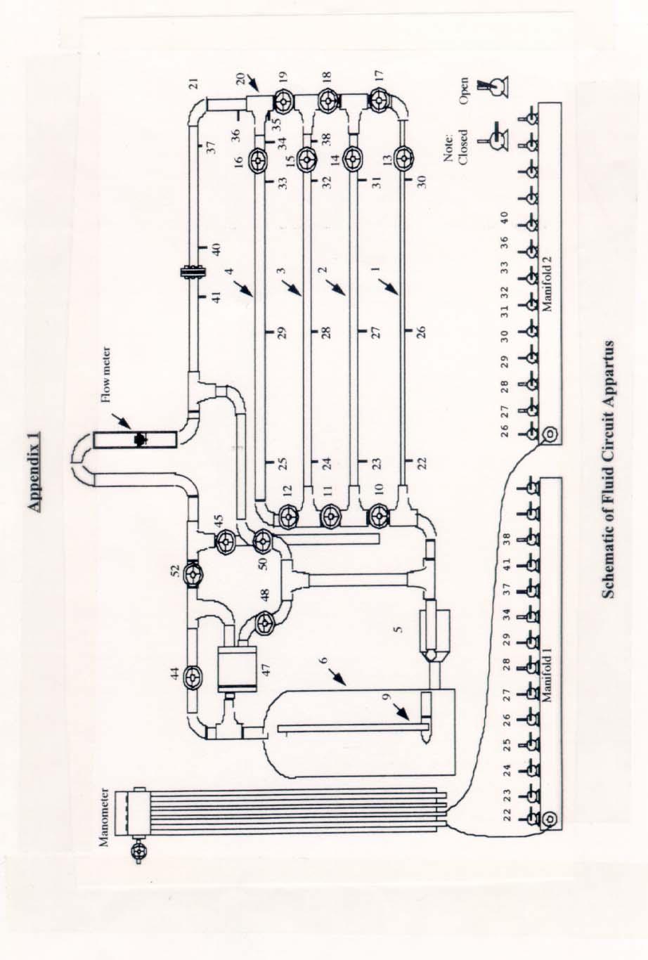
1 MEMORIAL UNIVERSITY OF NEWFOUNDLAND Faculty of Engineering and Applied Science FLUID MECHANICS LABORATORY PIPE FRICTION Objective To estimate the fluid pressure drops and roughness specifications for copper tubing of four different diameters. Lab The schematic of the apparatus is shown in appendix 1. The pressure drop will be estimated for the four copper tubes by measuring four different flow-rates. The pressure drops will also be measured using the differential pressure measurement device installed on the apparatus. The results will be compared to identify the pipe roughness specifications for the copper tubing. Theory In a horizontal pipeline flowing full, the head loss (h L ) between any two points is given by: p p h L = 1 2 γ 1
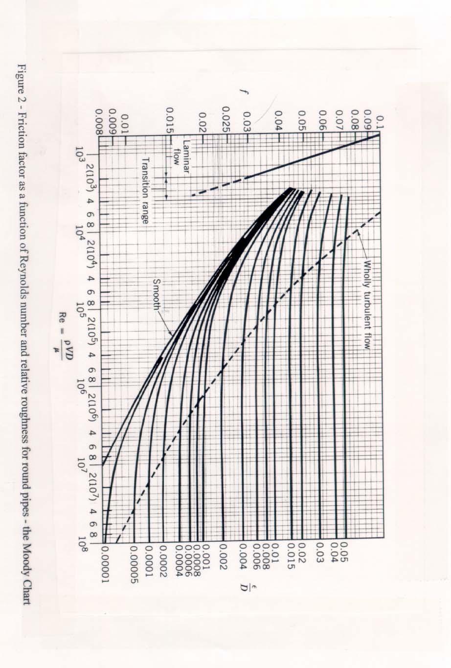
2 The friction factor, f, for flow of liquids in pipelines is defined as: hl f = 2 L V D 2g where L and D are the length and inside diameter of the pipe. The value of the friction factor is a function of the Reynolds Number (Re) and relative roughness (ε/d). Figure 2 shows the functional dependence of f on Re and ε/d and is called the Moody Diagram. Some salient features of the Moody Diagram are: (i) for very smooth pipes and for laminar flow, f is a function of Re only, and (ii) for wholly turbulent flow (as the Reynolds number becomes very high), f is a function of ε/d only. Experimental Procedure When the system has not been in use for quite some time, air bubbles will form in the vertical differential manometer tubes and the pipelines. The system should be purged of the air bubbles by following the procedure given below. 1. Close valve 45 and open all others. 2. Close all valves on the two manifolds. 3. Switch the pump on. The water and entrapped air in the system will be pumped through the flow meter and air bubbles will be observed coming out of the inlet to this meter. Wait until the system appears to be completely free of air. 4. Close valve 50. Close valve 48 slightly until the flow visualization tank starts to drain of water. To prevent the pump from burning out, do not fully close valve Open valve 22 on Manifold 1 and valve 30 on Manifold With the pump running, open the finger vent screw at the top of the manometer. Allow the water level in the manometer tubes to rise until it lows through the valve at the top. When you don t see any more air bubbles forming in the tube, close the finger vent screw and switch the pump off. 7. Slightly open the vent screw at the top of the manometer and allow the water levels in the manometer tubes to drop to about the midway point. Close the vent screw and ensure the water level in the manometer tubes are at the same level. 8. Close valve 22 on Manifold 1 and valve 30 on Manifold 2 The following is a list of valves to open for each pipeline: 2
3 Pipe 1-3/8 Copper Tubing ( mm I.D.) Open valves 13, 17, 18, 19, 52 and 44. Close valve 10 and all Manifold valves, except valve 22 on Manifold 1 and valve 30 on Manifold 2. Pipe 2-1/2 Copper Tubing ( mm I.D.) Open valves 10, 14, 18, 19 and 52. Close valves 11, 13 and 17. Close all Manifold valves except valve 23 on Manifold 1 and valve 31 on Manifold 2. Pipe 3-3/4 Copper Tubing ( mm I.D.) Open valves 10, 11, 15, 19 and 52. Close valves 13, 14, 17 and 18. Close all Manifold valves except valve 24 on Manifold 1 and valve 32 on Manifold 2. Pipe 4-1 Copper Tubing ( mm I.D.) Open valves 10, 11, 12, 16 and 52. Close valves 13, 14, 15, 17, 18 and 19. Close all Manifold valves except valve 25 on Manifold 1 and valve 33 on Manifold 2. When the appropriate valves are opened, the following procedure should be followed: (1) Reduce the flowrate using valve 52. (2) Record the flowrate from the flow meter and the pressure difference from the manometer. (3) Use four different flow rates for each pipeline. Results 1. Calculate the Reynolds Number, Re, and the friction factor, f for each of the runs on the four pipes. 2. Identify the roughness specifications (e.g., could the tubing be considered as Smooth Pipe? or estimate a relative roughness, ε/d, and the absolute roughness, ε, for each pipe) 3. Compare the results with values for new copper tubing and discuss your results. 3
4 4
5 5
6 Appendix 2 Data Sheet : Pipe Friction Pipe 1: I.D. = Pipe 2: I.D. = Pipe 3: I.D. = Pipe 4: I.D. = 6
Cover Page for Lab Report Group Portion. Head Losses in Pipes
 Cover Page for Lab Report Group Portion Head Losses in Pipes Prepared by Professor J. M. Cimbala, Penn State University Latest revision: 02 February 2012 Name 1: Name 2: Name 3: [Name 4: ] Date: Section
ME 333 Fluid Mechanics. Lab Session VISCOUS LOSSES IN PIPES
 ME 333 Fluid Mechanics Lab Session VISCOUS LOSSES IN PIPES Introduction Flow in pipes, laminar or turbulent, is subject to pressure losses that result from the viscous stresses on the wall of the pipe.
Experiment 8: Minor Losses
 Experiment 8: Minor Losses Purpose: To determine the loss factors for flow through a range of pipe fittings including bends, a contraction, an enlargement and a gate-valve. Introduction: Energy losses
Lab #4 Pipe Flow, Minor and Major Losses, and Walking in Osborne Reynolds Shoes CEE 331 Fall 2006
 CEE 331 Lab 4 Page 1 of 5 Lab #4 Pipe Flow, Minor and Major Losses, and Walking in Osborne Reynolds Shoes CEE 331 Fall 2006 Safety The major safety hazard in this laboratory is a shock hazard. Given that
Instruction Manual. Pipe Friction Training Panel
 Instruction Manual HL 102 Pipe Friction Training Panel 100 90 80 70 60 50 40 30 20 10 HL 102 Instruction Manual This manual must be kept by the unit. Before operating the unit: - Read this manual. - All
By Syed Ahmed Amin Shah 4 th semester Class No 8 Submitted To Engr. Saeed Ahmed
 EXPERIMENT # 01 DEMONSTRATION OF VARIOUS PARTS OF HYDRAULIC BENCH. HYDRAULIC BENCH Hydraulic bench is a very useful apparatus in hydraulics and fluid mechanics it is involved in majority of experiments
Operating Instructions
 Operating Instructions Note: 1. Never let the centrifugal pump run dry. 2. Make sure that there is at least one open path for water flow in the pipe network before turning the pump on. Never run the pump
EFFECTS OF CHEMICAL ADDITIVES ON THE PRESSURE DROP IN THE PIPES
 International Journal of Bio-Technology andresearch (IJBTR) ISSN(P): 2249-6858; ISSN(E): 2249-796X Vol. 4, Issue 1, Feb 2014, 1-6 TJPRC Pvt. Ltd. EFFECTS OF CHEMICAL ADDITIVES ON THE PRESSURE DROP IN THE
H16 Losses in Piping Systems
 H16 Losses in Piping Systems The equipment described in this manual is manufactured and distributed by TECQUIPMENT LIMITED Suppliers of technological laboratory equipment designed for teaching. BONSALL
Chapter 3 EXPERIMENTAL: EQUIPMENT, SET-UP, AND PROCEDURE
 Chapter 3 EXPERIMENTAL: EQUIPMENT, SET-UP, AND PROCEDURE 72 3.0 Introduction The experimental work was carried out in three stages. First stage: a laboratory scale single nozzle horizontal jet ejector
Cover Page for Lab Report Group Portion. Pump Performance
 Cover Page for Lab Report Group Portion Pump Performance Prepared by Professor J. M. Cimbala, Penn State University Latest revision: 02 March 2012 Name 1: Name 2: Name 3: [Name 4: ] Date: Section number:
Lab. Manual. Fluid Mechanics. The Department of Civil and Architectural Engineering
 Lab. Manual of Fluid Mechanics The Department of Civil and Architectural Engineering General Safety rules to be followed in Fluid Mechanics Lab: 1. Always wear shoes before entering lab. 2. Do not touch
The water supply for a hydroelectric plant is a reservoir with a large surface area. An outlet pipe takes the water to a turbine.
 Fluids 1a. [1 mark] The water supply for a hydroelectric plant is a reservoir with a large surface area. An outlet pipe takes the water to a turbine. State the difference in terms of the velocity of the
CHEM 355 EXPERIMENT 7. Viscosity of gases: Estimation of molecular diameter
 CHEM 355 EXPERIMENT 7 Viscosity of gases: Estimation of molecular diameter Expressed most simply, the viscosity of a fluid (liquid or gas) relates to its resistance to flow. The viscosity of a gas is determined
Operating Instructions
 Operating Instructions Before operating the thin film evaporator, please be aware of all safety concerns associated with this experiment: Burn hazard from the column and steam lines, Chemical hazards associated
Heat Pump Connections and Interior Piping
 Job Sheet 3 Heat Pump Connections and Interior Piping OBJECTIVES In this job sheet, you will observe how the presence of air in the ground loop affects the geothermal heat pump performance. You will also
Applied Fluid Mechanics
 Applied Fluid Mechanics 1. The Nature of Fluid and the Study of Fluid Mechanics 2. Viscosity of Fluid 3. Pressure Measurement 4. Forces Due to Static Fluid 5. Buoyancy and Stability 6. Flow of Fluid and
OIL SUPPLY SYSTEMS ABOVE 45kW OUTPUT 4.1 Oil Supply
 OIL SUPPLY SYSTEMS ABOVE 45kW OUTPUT 4.1 Oil Supply 4.1.1 General The primary function of a system for handling fuel oil is to transfer oil from the storage tank to the oil burner at specified conditions
MEMORANDUM. Investigation of Variability of Bourdon Gauge Sets in the Chemical Engineering Transport Laboratory
 1 MEMORANDUM TO: FROM: Prof. Davis Hubbard Prof. Faith A. Morrison DATE: 22 April 2014 RE: Investigation of Variability of Bourdon Gauge Sets in the Chemical Engineering Transport Laboratory Introduction
CVEN 311 Fluid Dynamics Fall Semester 2011 Dr. Kelly Brumbelow, Texas A&M University. Final Exam
 CVEN 311 Fluid Dynamics Fall Semester 2011 Dr. Kelly Brumbelow, Texas A&M University Final Exam 8 pages, front & back, not including reference sheets; 21 questions An excerpt from the NCEES Fundamentals
AE50S Automatic Air and Gas Vent for Liquid Systems Installation and Maintenance Instructions
 0176050/3 IM-P017-11 ST Issue 3 AE50S Automatic Air and Gas Vent for Liquid Systems Installation and Maintenance Instructions 1 General safety information 2 General product information 3 Installation 4
Flow transients in multiphase pipelines
 Flow transients in multiphase pipelines David Wiszniewski School of Mechanical Engineering, University of Western Australia Prof. Ole Jørgen Nydal Multiphase Flow Laboratory, Norwegian University of Science
HYDRAULICS. H89.8D - Hydraulic Bench
 HYDRAULICS H89.8D - Hydraulic Bench 1. General The H89.8D and ancillary equipment have been developed to provide a comprehensive range of experiments in fluid mechanics. The bench is of robust construction
MOL LNG Transport (Europe) Ltd File: 02 Checklists 6 pages Rev. No. 1 Loading Plan Part Two (2) (Line UP) Loading Plan Part Two (2) (Line Up)
 Ltd File: 02 Checklists 6 pages Rev. No. 1 Loading Plan Part Two (2) (Line UP) Loading Plan Part Two (2) (Line Up)") Loading Plan Part Two (2) (Line Up) Arm Cool Down; Line Cool Down Line Up: Set up the port manifold as follows:. Open 20% No.1 tank filling valve CL100 Open 20% No. 2 tank filling valve CL200 Open 20%
Loading Plan Part Two (2) (Line Up) Arm Cool Down; Line Cool Down Line Up: Set up the port manifold as follows:. Open 20% No.1 tank filling valve CL100 Open 20% No. 2 tank filling valve CL200 Open 20%
Blue River Technologies Port-A-Poly Mixer w/2.5 GPH LMI Pump And Secondary Water Dilution Line INSTALLATION AND OPERATION
 Blue River Technologies Port-A-Poly Mixer w/2.5 GPH LMI Pump And Secondary Water Dilution Line INSTALLATION AND OPERATION Install your Blue River Technologies Port-A-Poly mixing system in a clean dry area.
Write important assumptions used in derivation of Bernoulli s equation. Apart from an airplane wing, give an example based on Bernoulli s principle
 HW#3 Sum07 #1. Answer in 4 to 5 lines in the space provided for each question: (a) A tank partially filled with water has a balloon well below the free surface and anchored to the bottom by a string. The
TANK MATE INCLUDES: TOOLS REQUIRED: CONRADER VALVES 3/4 WRENCH **TUBING CUTTERS TEE PETCOCK TEE ASSEMBLY 8 FOOT NYLON TUBING
 CONRADER VALVES TANK MATE AUTOMATIC DRAIN VALVE INSTALLATION KIT INCLUDES: TEE PETCOCK TEE ASSEMBLY 8 FOOT NYLON TUBING WV-1 DRAIN VALVE TOOLS REQUIRED: 3/4 WRENCH **TUBING CUTTERS ** NEEDED TO CUT METAL
Digester Processes. 1. Raw Sludge Pumping System
 Digester Processes 1. Raw Sludge Pumping System Removes accumulated sludge from the primary clarifiers, pumped through 1 of 2 pipes either 150 or 200mm in diameter (Fig. 1.1). Fig 1.1 Pipes feeding Digesters
MASS TRANSFER LAB. Make & Model. S. No. Equipment
 MASS TRANSFER LAB S. No. Equipment Make & Model Manufacture Qty 1 Liquid / Liquid Extraction Unit UOP5-A Armfield 1 2 Gas Liquid Absorption UOP7-A Armfield 1 3 Diffusion of a Liquid Apparatus CER A-A Armfield
CPE562 Chemical Process Control HOMEWORK #1 PROCESS & INSTRUMENTATION DIAGRAM
 Faculty of Chemical Engineering CPE562 Chemical Process Control HOMEWORK #1 PROCESS & INSTRUMENTATION DIAGRAM SUBMISSION DATE: 1 OCT. 2012 Question 1 Name the following equipments based on standard P&ID
Single & Headered Relief Vent Piping Analysis
 Single & Headered Relief Vent Piping Analysis Todd Jekel, Ph.D., P.E. Industrial Refrigeration Consortium 2005 Research & Technology Forum January 21, 2005 Madison, WI 1 Purpose Vent piping requirements
and its weight (in newtons) when located on a planet with an acceleration of gravity equal to 4.0 ft/s 2.
 when located on a planet with an acceleration of gravity equal to 4.0 ft/s 2.") 1.26. A certain object weighs 300 N at the earth's surface. Determine the mass of the object (in kilograms) and its weight (in newtons) when located on a planet with an acceleration of gravity equal to
1.26. A certain object weighs 300 N at the earth's surface. Determine the mass of the object (in kilograms) and its weight (in newtons) when located on a planet with an acceleration of gravity equal to
Assistant Lecturer Anees Kadhum AL Saadi
 Pressure Variation with Depth Pressure in a static fluid does not change in the horizontal direction as the horizontal forces balance each other out. However, pressure in a static fluid does change with
MET 335W Fluid Mechanics Laboratory. Lab 1: Bourdon Tube Calibration. Nick Peak
 MET 335W Fluid Mechanics Laboratory Lab 1: Bourdon Tube Calibration Nick Peak January 15, 2018 Purpose The purpose of this experiment is to test the accuracy of a bourdon pressure gauge. This is accomplished
Rules for Classification and Construction Additional Rules and Guidelines 3 Machinery Installations
 VI Rules for Classification and Construction Additional Rules and Guidelines 3 Machinery Installations 6 Guidelines for the Construction, Equipment and Testing of Closed Fuel Oil Overflow Systems Edition
Cash Valve TYPE KP PILOT OPERATED BACK PRESSURE VALVE. ISSUED - DECEMBER 2000 CAVMC-0518-US-0208 ISO 9001 Certified
 Cash Valve PILOT OPERATED BACK PRESSURE VALVE ISSUED - DECEMBER 2000 CAVMC-0518-US-0208 ISO 01 Certified KP HIGH CAPACITY PILOT OPERATED BACK PRESSURE VALVE DESCRIPTION The Cash Valve Type KP is a pilot
PRESSURE DROP CHARTS
 PRESSURE DROP FOR SMALL PEX TUBING AT 100 F Take the total heat load (BTUH) for the area that the loop is covering and divide it by 501. Divide the result with the Delta-T to find GPM for the loop. Find
SPH 4C Unit 4 Hydraulics and Pneumatic Systems
 SPH 4C Unit 4 Hydraulics and Pneumatic Systems Properties of Fluids and Pressure Learning Goal: I can explain the properties of fluids and identify associated units. Definitions: Fluid: A substance that
DARSHAN INSTITUTE OF ENGINEERING AND TECHNOLOGY
 DARSHAN INSTITUTE OF ENGINEERING AND TECHNOLOGY FLUID MECHANICS (2141906) INDEX Sr. No. 1. 2. 3. 4. Experiment Start Date End Date Sign Grade To validate Bernoulli s theorem as applied to the flow of water
Module 6. Tightness Testing
 Module 6 Tightness Testing IGE / UP / 1B New Tightness Testing Procedure Covers pipework up to 35mm and installation volumes of 0.035m3 Objectives By the end of Module 6, Tightness Testing and Direct Purging
THERMODYNAMICS, HEAT AND MASS TRANSFER TUTORIAL NO: 1 (SPECIFIC VOLUME, PRESSURE AND TEMPERATURE)
") THERMODYNAMICS, HEAT AND MASS TRANSFER TUTORIAL NO: 1 (SPECIFIC VOLUME, PRESSURE AND TEMPERATURE) 1. A vacuum gauge mounted on a condenser reads 66 cm Hg. What is the absolute pressure in the condenser
THERMODYNAMICS, HEAT AND MASS TRANSFER TUTORIAL NO: 1 (SPECIFIC VOLUME, PRESSURE AND TEMPERATURE) 1. A vacuum gauge mounted on a condenser reads 66 cm Hg. What is the absolute pressure in the condenser
The Discussion of this exercise covers the following points:
 Exercise 3-2 Orifice Plates EXERCISE OBJECTIVE In this exercise, you will study how differential pressure flowmeters operate. You will describe the relationship between the flow rate and the pressure drop
Unit Test Review. Pressure Valve Pump Surfactant Viscosity Plimsoll line Density Units for density Neutral buoyancy Pipeline pig
 Pressure Valve Pump Surfactant Viscosity Plimsoll line Density Units for density Neutral buoyancy Pipeline pig Unit Test Review 4. What properties affect or change the density of a substance? 5. Describe
Bladder Tank Installation & System Design Information
 Bladder Tank Installation & System Design Information The Chemguard Bladder Tank is one component in a balanced pressure foam proportioning fire protection system. It requires no external power other than
Model PDT Dewpoint Transmitter
 Model PDT Dewpoint Transmitter Instruction Manual Alpha Moisture Systems Alpha House 96 City Road Bradford BD8 8ES England Tel: +44 1274 733100 Fax: +44 1274 733200 email: mail@amsytems.co.uk web: www.amsystems.co.uk
The Discussion of this exercise covers the following points:
 Exercise 5-3 Wet Reference Leg EXERCISE OBJECTIVE Learn to measure the level in a vessel using a wet reference leg. DISCUSSION OUTLINE The Discussion of this exercise covers the following points: Measuring
CASH VALVE TYPE KP BACK PRESSURE VALVES
 A high capacity pilot operated back pressure valve that offers accurate control and dependable protection against overpressure conditions FEATURES Automatically maintains maximum pressure in a vessel or
3. A fluid is forced through a pipe of changing cross section as shown. In which section would the pressure of the fluid be a minimum?
 AP Physics Multiple Choice Practice Fluid Mechanics 1. A cork has weight mg and density 5% of water s density. A string is tied around the cork and attached to the bottom of a water-filled container. The
WARNING: Gas Conversion Kit Instructions Applies to: Model UDAP, UDAS, UDBP, and UDBS Unit Heaters. General and Warnings FOR YOUR SAFETY
 Form CP-UD-GC Obsoletes I-UD-GC (Version E) Gas Conversion Kit Instructions Applies to: Model UDAP, UDAS, UDBP, and UDBS Unit Heaters General and Warnings All gas conversion must be done by a qualified
N2 Blanketing Valve DST100 / DST200 TYPE INSTRUCTION MANUAL CONTENTS K.S.P.C. General Description Operation. Installation Maintenance
 DST100 / DST200 TYPE N2 Blanketing Valve INSTRUCTION MANUAL CONTENTS General Description Operation Installation Maintenance K.S.P.C 488-1 Wolha-ro, Tongjin-eup, Gimpo-si, Gyeonggi-Do, Korea Tel : +82-31-998-3825~7
Lab Problems. Lab Problems for Chapter Fluid Characterization by Use of a Stormer Viscometer L-1
 Lab Problems This section contains end-of-the-chapter problems that involve data obtained from various simple laboratory experiments. These lab problems for any chapter can be obtained by clicking on the
2. Determine how the mass transfer rate is affected by gas flow rate and liquid flow rate.
 Goals for Gas Absorption Experiment: 1. Evaluate the performance of packed gas-liquid absorption tower. 2. Determine how the mass transfer rate is affected by gas flow rate and liquid flow rate. 3. Consider
Irrigation &Hydraulics Department lb / ft to kg/lit.
 CAIRO UNIVERSITY FLUID MECHANICS Faculty of Engineering nd Year CIVIL ENG. Irrigation &Hydraulics Department 010-011 1. FLUID PROPERTIES 1. Identify the dimensions and units for the following engineering
FLUID POWER FLUID POWER EQUIPMENT TUTORIAL ACCUMULATORS. This work covers part of outcome 2 of the Edexcel standard module:
 FLUID POWER FLUID POWER EQUIPMENT TUTORIAL ACCUMULATORS This work covers part of outcome 2 of the Edexcel standard module: UNIT 21746P APPLIED PNEUMATICS AND HYDRAULICS The material needed for outcome
Water Weir Flow Controller. Introduction. Safety Precautions. Mounting the Hardware
 57007-88 Introduction Safety Precautions This instruction sheet describes how to set up and use the Hach (Figure 1). A water weir is a device that raises or diverts water to regulate the flow. Hach s water
Third measurement MEASUREMENT OF PRESSURE
 1. Pressure gauges using liquids Third measurement MEASUREMENT OF PRESSURE U tube manometers are the simplest instruments to measure pressure with. In Fig.22 there can be seen three kinds of U tube manometers
AIR FRACTIONS IMPACT OVER PRESSURE DROP IN AIR- WATER MIXTURE FLOW
 U.P.B. Sci. Bull., Series D, Vol. 79, Iss. 4, 2017 ISSN 1454-2358 AIR FRACTIONS IMPACT OVER PRESSURE DROP IN AIR- WATER MIXTURE FLOW Corina BONCESCU 1, Diana ROBESCU 2 The pressure drop in air-water mixture
SERIES 500 VARIABLE RANGE PNEUMATIC DIFFERENTIAL PRESSURE TRANSMITTER
 Man500e 09/2006 Installation Operation and Maintenance Instructions SERIES 500 VARIABLE RANGE PNEUMATIC DIFFERENTIAL PRESSURE TRANSMITTER INDEX 1. INSTALLATION 2. COMPRESSED AIR SUPPLY 3. FLOW MEASURE
EXPERIMENT XI. Careful!! Improper handling of the vacuum line may result in the release of SO 2 which is an irritating and suffocating gas.
 Chem 366-3 Page XI - 1 EXPERIMENT XI INFRARED SPECTRUM OF SO2 (S&G, 5th ed. Expt 36, 6th ed. Expt. 35) 1. Pre-Lab preparation. The description of this experiment has disappeared from the more recent editions
Experiment (13): Flow channel
: Flow channel") Experiment (13): Flow channel Introduction: An open channel is a duct in which the liquid flows with a free surface exposed to atmospheric pressure. Along the length of the duct, the pressure at the surface
Experiment (13): Flow channel Introduction: An open channel is a duct in which the liquid flows with a free surface exposed to atmospheric pressure. Along the length of the duct, the pressure at the surface
Cell Disruption System
 BioNeb Cell Disruption System* Instruction Manual * U.S. patent number 550100 International patents issued and pending BioNeb Cell Disruption System Instruction Manual Version 3.0, April, 2000 Edited by:
Installation and Operation 370ESP (Electric Single-Point Purger) & 370ESPR (Retrofit Purger)
 & 370ESPR (Retrofit Purger)") IB-77 Installation and Operation 370ESP (Electric Single-Point Purger) & 370ESPR (Retrofit Purger) These installation, operation and technical instructions should be used by experienced personnel as a
IB-77 Installation and Operation 370ESP (Electric Single-Point Purger) & 370ESPR (Retrofit Purger) These installation, operation and technical instructions should be used by experienced personnel as a
THE INNER WORKINGS OF A SIPHON Jacques Chaurette p. eng. January 2003
 THE INNER WORKINGS OF A SIPHON Jacques Chaurette p. eng. www.lightmypump.com January 2003 Synopsis The objective of this article is to explain how a siphon works. The difference between low pressure, atmospheric
Experiment Instructions. Circulating Pumps Training Panel
 Experiment Instructions Circulating Pumps Training Panel Experiment Instructions This manual must be kept by the unit. Before operating the unit: - Read this manual. - All participants must be instructed
Lecture 22: Ageostrophic motion and Ekman layers
 Lecture 22: Ageostrophic motion and Ekman layers November 5, 2003 1 Subgeostrophic flow: the Ekman layer Before returning to our discussion of the general circulation of the atmosphere in Chapter 8, we
Static Fluids. **All simulations and videos required for this package can be found on my website, here:
 DP Physics HL Static Fluids **All simulations and videos required for this package can be found on my website, here: http://ismackinsey.weebly.com/fluids-hl.html Fluids are substances that can flow, so
To plot the following performance characteristics; A pump is a device, which lifts water from a lower level to a higher
 LABORATORY MANUAL ON RECIPROCATING PUMP TEST RIG Prepared By Prof. (Dr.) M. K. Roul Professor and Principal Department of Mechanical Engineering Gandhi Institute for Technological Advancement (GITA), Bhubaneswar-752054
Ball Float Steam Trap UNA 43 PN 16/CL 125/JIS 10K UNA 46 PN 40/CL 150/CL 300/JIS 10K/JIS 20K DN 80, 100, 150, 3", 4", 6"
 Data Sheet 819584-00 Issue Date: 01/17 Ball Float Steam Trap UNA 43 PN 16/C 125/JIS 10K UNA 46 PN 40/C 150/C 300/JIS 10K/JIS 20K DN 80, 100, 150, 3", 4", 6" UNA 43 hl, UNA 46 hl UNA 43 v, UNA 46 v with
 Hydrostatic pressure Consider a tank of fluid which contains a very thin plate of (neutrally buoyant) material with area A. This situation is shown in Figure below. If the plate is in equilibrium (it does
Flow in a shock tube
 Flow in a shock tube April 30, 05 Summary In the lab the shock Mach number as well as the Mach number downstream the moving shock are determined for different pressure ratios between the high and low pressure
Hours / 100 Marks Seat No.
 17421 21415 3 Hours / 100 Marks Seat No. Instructions : (1) All Questions are compulsory. (2) Answer each next main Question on a new page. (3) Illustrate your answers with neat sketches wherever necessary.
Tutorial. BOSfluids. Relief valve
 Tutorial Relief valve The Relief valve tutorial describes the theory and modeling process of a pressure relief valve or safety valve. It covers the algorithm BOSfluids uses to model the valve and a worked
UNLOADING PROCEDURE OF AN AIRFLOW CONTAINER
 UNLOADING PROCEDURE OF AN AIRFLOW CONTAINER LCO2 / LN2O 1-07.05.13 PHASE 1 : Preliminary check and first manipulations before the discharge 1. Security rules 1. Wear all required safety equipments for
PRESSURE REDUCING VALVE RP45 (EN)
") PRESSURE REDUCING VALVE RP45 (EN) DESCRIPTION The ADCA RP45 series pressure reducing valves are single seat bellows sealed controllers, operating without auxiliary energy, designed for use on steam, compressed
PRESSURE REDUCING VALVE RP45 (EN) DESCRIPTION The ADCA RP45 series pressure reducing valves are single seat bellows sealed controllers, operating without auxiliary energy, designed for use on steam, compressed
Orifice Plate Flow Meter
 Orifice Plate Flow Meter FOFT Measuring Principle The principle of measuring the differential pressure is based on the fact that a differential pressure is created across that section of a pipe where its
Exercise 5-2. Bubblers EXERCISE OBJECTIVE DISCUSSION OUTLINE. Bubblers DISCUSSION. Learn to measure the level in a vessel using a bubbler.
 Exercise 5-2 Bubblers EXERCISE OBJECTIVE Learn to measure the level in a vessel using a bubbler. DISCUSSION OUTLINE The Discussion of this exercise covers the following points: Bubblers How to measure
Lab 3 Introduction to Quantitative Analysis: Pumps and Measurements of Flow
 Georgia Institute of Technology School of Earth and Atmospheric Sciences EAS 4641, Spring 2008 Lab 3 Introduction to Quantitative Analysis: Pumps and Measurements of Flow Purpose of Lab 3: 1) To gain a
TEST SPECIFICATION NYT-909-C
 748 Starbuck Ave, Watertown, NY 13601 Phone: +1-315-786-5200 Engineering Fax: +1-315-786-5673 TEST SPECIFICATION NYT-909-C CODE OF TESTS FOR TESTING "AB" TEST RACK P/N 702546 & 702612 ISSUE NO. 5 1.0 THE
1. The principle of fluid pressure that is used in hydraulic brakes or lifts is that:
 University Physics (Prof. David Flory) Chapt_15 Thursday, November 15, 2007 Page 1 Name: Date: 1. The principle of fluid pressure that is used in hydraulic brakes or lifts is that: A) pressure is the same
CHAPTER 2 EXPERIMENTAL SETUP AND PROCEDURE
 22 CHAPTER 2 EXPERIMENTAL SETUP AND PROCEDURE 2.1 EXPERIMENTAL COLUMN All the experiments were carried out in an internal loop airlift fluidized bed and combined loop fluidized bed (an external down comer
Installation, operating and maintenance Instructions for Seemag bypass level indicator
 Issue: S Date: 05-09-14 Type G35 General information The Seetru bypass magnetic level indicator, abbreviate SEEMAG, serves to show the filling level of fluids in tanks, basins, tubes etc. The Seemag operates
RESEARCH OF BLOCKAGE SEGMENT DETECTION IN WATER SUPPLY PIPELINE BASED ON FLUID TRANSIENT ANALYSIS ABSTRACT
 RESEARCH OF BLOCKAGE SEGMENT DETECTION IN WATER SUPPLY PIPELINE BASED ON FLUID TRANSIENT ANALYSIS Ying Xu 2, Yuebin Wu 1, Liang Chen 1, Yun Guo 2, Wei Wang 1 and Zhe Ding 2 1 School of Architecture, Harbin
Cover Page for Lab Report Group Portion. Drag on Spheres
 Cover Page for Lab Report Group Portion Drag on Spheres Prepared by Professor J. M. Cimbala, Penn State University Latest revision: 29 September 2017 Name 1: Name 2: Name 3: [Name 4: ] Date: Section number:
The following article was authored by Jacques Chaurette of Fluide Design, Inc. ( All rights reserved. - HOW DOES A SIPHON WORK?
 The following article was authored by Jacques Chaurette of Fluide Design, Inc. (www.fluidedesign.com) All rights reserved. - HOW DOES A SIPHON WORK? - A siphon is a length of tubing that allows you to
System Pressure Manager Standard & System Pressure Manager Plus
 System Pressure Manager Standard & System Pressure Manager Plus Installation, Commissioning & Servicing Instructions Note: THESE INSTRUCTIONS MUST BE READ AND UNDERSTOOD BEFORE INSTALLING, COMMISSIONING,
Captains Meeting 2009 Introduction to Well Testing- Expro. Edwin Schoorl
 Captains Meeting 2009 Introduction to Well Testing- Expro Edwin Schoorl Agenda Oil and Gas presence Well construction Well testing Welltest System Welltest Equipment Welltest Video Questions Oil and gas
Ir HN Lam BSc(Eng), MSc(Eng), CEng, MIMechE, MCIBSE, MASHRAE, MASME, MHKIE. Test Report on Non-Return Valve for Water Closets
, MSc(Eng), CEng, MIMechE, MCIBSE, MASHRAE, MASME, MHKIE. Test Report on Non-Return Valve for Water Closets") c/o Department of Mechanical Engineering University of Hong Kong Pokfulam Road Hong Kong Phone: 28592640 E-mail: hn.lam.hku@hku.hk Ir HN Lam BSc(Eng), MSc(Eng), CEng, MIMechE, MCIBSE, MASHRAE, MASME, MHKIE
c/o Department of Mechanical Engineering University of Hong Kong Pokfulam Road Hong Kong Phone: 28592640 E-mail: hn.lam.hku@hku.hk Ir HN Lam BSc(Eng), MSc(Eng), CEng, MIMechE, MCIBSE, MASHRAE, MASME, MHKIE
Pumping Systems for Landscaping Pumps, Controls and Accessories. Mark Snyder, PE
 October 21, 2010 Pumping Systems for Landscaping Pumps, Controls and Accessories Mark Snyder, PE Pump Station Design Purpose of Pump Stations Pump stations are designed to boost water pressure from a lower
Lab #1 Pressure: Bubblers and Water Balloons CEE 331 Fall 2003
 CEE 331 Lab 1 Page 1 of 9 SAFETY Lab #1 Pressure: Bubblers and Water Balloons CEE 331 Fall 2003 Laboratory exercise based on an exercise developed by Dr. Monroe Weber-Shirk The major safety hazard in this
FOR INSTALLING CO 2 BLENDER KIT (P/N IN BEER SYSTEM
 IMI CORNELIUS INC One Cornelius Place Anoka, MN 55303-623 Telephone (800) 238-3600 Facsimile (612) 22-326 INSTALLATION INSTRUCTIONS FOR INSTALLING CO 2 BLENDER KIT (P/N 111612000 IN BEER SYSTEM SECONDARY
Installation Guide. buoy.ai
 Installation Guide buoy.ai Notes In the Box Buoy unit Battery and Charger assembly 3/4 meter couplings (2) Rubber gaskets (6) Also included: Buoy Quick Start Guide Buoy Installation Guide Buoy sticker
Orifice & Free Jet Flow. Instruction Manual F1-17 ISSUE 8
 Orifice & Free Jet Flow Instruction Manual F1-17 ISSUE 8 November 2013 Table of Contents Copyright and Trademarks... 1 General Overview... 2 Equipment Diagrams... 3 Important Safety Information... 4 Introduction...
Dean Pump Self-Priming Chemical Process Pumps
 Bulletin C 1.2.34.7 Dean Pump Self-Priming Chemical Process Pumps php Series HEAD CAPACITY RANGE CHARTS php Self Primer - 2 Pole 3500 RPM 500 CAPACITY M 3 /HR 2900 RPM 50 HERTZ 25 50 75 125 150 400 TOTAL
Chapter 13 Fluids. Copyright 2009 Pearson Education, Inc.
 Chapter 13 Fluids Phases of Matter Density and Specific Gravity Pressure in Fluids Atmospheric Pressure and Gauge Pressure Pascal s Principle Units of Chapter 13 Measurement of Pressure; Gauges and the
G SPECIFICATION: TITLE: VOLUME: 4 REVISIONS:
 SPECIFICATION: G-2040-7 TITLE: REQUIREMENTS FOR THE INSTALLATION OF GAS BOOSTERS AND BACK PRESSURE/SUCTION PROTECTIVE DEVICES IN VOLUME: 4 REVISIONS: Totally re-written. G-2040-7 Gas Operations Standards
This experiment will develop skills in graphing and graphical analysis.
 Chapter 11 Fluid Flow 11.1 Purpose The purpose of this experiment is to measure water flow through capillary tubes at different pressures, to study resistance to flow using tubes of different diameter,
Pressure Control. where: p is the pressure F is the normal component of the force A is the area
 Pressure Control First of all, what is pressure, the property we want to control? From Wikipedia, the free encyclopedia. Pressure is the application of force to a surface, and the concentration of that
Basic Flows in a Microfluidic Device
 Basic Flows in a Microfluidic Device Vishal Tandon 1 Introduction Microfluidic devices are used to transport, mix, and separate analytes in small sample volumes for chemical or biological analysis. Understanding
Slide 5 / What is the difference between the pressure on the bottom of a pool and the pressure on the water surface? A ρgh B ρg/h C ρ/gh D gh/ρ
 Slide 1 / 47 1 Two substances mercury with a density 13600 kg/m3 and alcohol with a density 800 kg/m3 are selected for an experiment. If the experiment requires equal masses of each liquid, what is the
Laboratory studies of water column separation
 IOP Conference Series: Materials Science and Engineering OPEN ACCESS Laboratory studies of water column separation To cite this article: R Autrique and E Rodal 2013 IOP Conf. Ser.: Mater. Sci. Eng. 52