EFFECTS OF BACK-PRESSURE SATURATION TECHNIQUES ON RESULTS OF R TRIAXIAL COMPRESSION TESTS
|
|
|
- Rosamond Barber
- 5 years ago
- Views:
Transcription

1 I \ REFERENCE MISCELLANEOUS PAPER GL EFFECTS OF BACK-PRESSURE SATURATION - TECHNIQUES ON RESULTS OF R TRIAXIAL COMPRESSION TESTS by Robert: T. Donaghe and Frank C. Ton send Geotehnial Laboratory U. S. Army Engineer Waterays Experiment Station P.. Box 631, Viksburg, Miss May 1979 Final Report Approved For Publi Release; Distribut ion Unlimited -I Prepared for Offie, Chief of Engineers, U. S. Army Washington, D. C Under CWIS 17 4 library BAANCH TECHNICAL INFORMATtON CENTER lis ARMY ENGINEER WATERWAYS EXPERIMENT STA IIln
 EFFECTS OF BACK- PRESSURE SATURATION TECHNIQUES ON RESULTS OF R TRIAXIAL COMPRESSION TESTS.")
2 Unlassified SECURITY C LASSIFICATIO N OF THIS PAG E (When Data Entered) READ INSTRUCTIONS REPORT DOCUMENTATION PAGE BE FORE COMPLETING F ORM 1. REPORT NUMBER 2. GOVT A C CESSION NO. 3. R ECIP IENT'S C A T A LOG N U MBER Misellaneous Paper GL TITLE ( and Subtitl e) EFFECTS OF BACK- PRESSURE SATURATION TECHNIQUES ON RESULTS OF R TRIAXIAL COMPRESSION TESTS. TYPE OF REPO R T & P E RIOD COV E R ED Final report 6. PERFORMI N G ORG. REPORT N UM B E R 7. AUTHOR( a) Robert T. Donaghe Fr ank C. Tonsend 8. CON TR ACT OR GRAN T NUM BER( a) 9. P E RFORMING O RGANI Z A T IO N N AM E AN D A DDRESS U. S. Army Engineer Waterays Experiment Station Geotehnial Laboratory P.. Box 631, Viksburg, Miss PROGRAM ELEM ENT, PROJECT, TASK ARE A a WORK UNIT N U MBERS CWIS CON T ROLLING OFF ICE NAME AND A DDR ESS Offi e, Chi ef of Engineer s, U. S. Army Washington, D. C REPORT D ATE May N UMBER OF PAGES MO N I T ORIN G A G ENCY NAME a A DDR ESS(ll dllla rant from Controlling Olll e) 1. SECURITY CLASS. ( o f th/e report) Unlassified 1 a. D ECL ASSI F I C ATION/ DOWNGRAD ING SC H EDULE 16. D I STRI BUT ION STATE MENT (of thle Report) Approved for publi release ; distri bution unlimi ted. 17. DIST RI B U TION ST ATEM E NT (o f the a betra t entered In Blok 2, II different from Repor t) 18. SUPPL E MEN T ARY N O T ES This i nvestigation as onduted as a par t of a study to evaluate laborator y testing proedur es for the Offie, Chief of Engineers (OCE), under CWIS 174 of the Engineering Studies Progr am. 19. KEY WO RDS ( Contin ue on reverse aide if ne esaary snd I dentity by blok n um ber) Bak pressure Bak pressure saturation R tests (Soils) Saturation (Soils) Triaxial shear tests 2, ABSTRACT (C4ut.Eaue ea.,.,..r_ lfi.o I f nee«e.ey.ad. Identify by blok number) Corps of Engineers (CE) soil l aboratories ahieve 1 perent saturation of R and R triaxial ompression test speimens by the use of bak pressure applied i n small inrements onurrently ith inrease in hamber pressure ith adequat e time beteen i nrements to per mit equalization of pore-ater pr essure t hroughout the speimen. The obj etive of thi s proedure i s to apply suf f i ient pr essure on the por e ater and por e air so that the ai r is dissolved in DD FOAM 'JAN n 1473 EDrTION OF f NOV 6 IS OBSOLETE Unlassified (Continued) SECUAlTY CLASSIFIC ATION OF THIS PAGE ( When D eta E n tered)

3 Unlassified SECURITY CLASSIFICATION OF THIS PAGE(When Date Entered) 2. ABSTRACT (Continued). the pore ater ithout signifiantly prestressing (overonsolidating) the speimen. The objetives of this investigation ere to determine the effets of the magnitude of bak pressure and the proedure by hih it is applied on the stress deformation harateristis of soils. The objetives ere ahieved by omparing results of tests performed on ompated speimens of Viksburg loess (layey silt (ML)) and Viksburg bukshot (plasti lay (CH)) in hih the bakpressure saturation proedure as varied and results of tests performed on speimens of Viksburg bukshot onsolidated from a slurry in hih the magnitude of the total bak pressure as varied. The results indiate that variations in the tehnique of applying bak pressure may signifiantly affet test results. Hoever, there are no signifiant effets on test results if proedures outlined in the CE soils testing manual are folloed ; i. e., results are not signifiantly affeted if the effetive onsolidation stress during saturation does not exeed psi and the magnitude of bak- pressure inrements is ontrolled so that the effetive stress on the speimen is less than the desired onsolidation pressure. Appendix A presents the bak- pressure saturation proedure speified in Engineer Manual Appendies B and C of the report ontain desriptions of an automati bak- pressure saturation devie that dupliates the saturation proedure outlined in the CE soils testing manual and of a differential vauum saturation proedure that enables speimens to be saturated using bak pressures equal to field hydrostati onditions, respetively. Unlassified SECURITY CL A SSI FIC ATION O F THIS PAGE( When Dele Entered)

4 THE CONTENTS OF THIS REPORT ARE NOT TO BE USED FOR ADVERTISING, PUBLICATION, OR PROMOTIONAL PURPOSES. CITATION OF TRADE NAMES DOES NOT CONSTITUTE AN OFFICIAL EN DORSEMENT OR APPROVAL OF THE USE OF SUCH COMMERCIAL PRODUCTS. 1
 16) of the Engineering Studies Program. The testing as performed during the period January through September 197.")
5 PREFACE The investigation reported herein as onduted as a part of a study to evaluate laboratory testing proedures for the Offie, Chief of Engineers, U. S. Army, under CWIS 174 (formerly Engineering Study (ES) 16) of the Engineering Studies Program. The testing as performed during the period January through September 197. The saturation apparatus as designed and fabriated in the Geotehnial Laboratory (GL), at the U. S. Army Engineer Waterays Experiment Station (WES), CE, by Messrs. Robert T. Donaghe and Thomas V. MEen. The study as onduted by Mr. Donaghe under the supervision of Dr. F. C. Tonsend, Former Chief, Soils Researh Faility, Soil Mehanis Division (SMD), GL, and the general diretion of Mr. C. L. MAnear, Chief, SMD, GL. Messrs. J. P. Sale and R. G. Ahlvin ere Chief and Assistant Chief, respetively, GL. This report as prepared by Mr. Donaghe and Dr. Tonsend. COL G. H. Hilt, CE, and COL J. L. Cannon, CE, ere Diretors of the WES during the investigation and the preparation of this report. Mr. F. R. Bron as Tehnial Diretor. 2

6 CONTENTS PREFACE CONVERSION FACTORS, U. S. CUSTOMARY TO METRIC (SI) UNITS OF MEASUREMENT PART I : INTRODUCTION... Purpose and Sope... Bakground Information. PART II : TESTING PROGRAM AND MATERIALS. Testing Program Materials.. Desription of Equipment.. Preparation of Speimens.. Testing Proedure..... PART III : TEST RESULTS AND DISCUSSION Effets of Magnitude of Bak- Pressure Inrements, ML Material Effet of Magnitude of Effetive Stress Indued by Bak Pr essure, CH Material.... Effet of Magnitude of a During Saturation, CH and ML Materials.. :.... Effet of Magnit ude of Total Bak Pressure... CH Mater ial Consoli dated from a Slurry PART IV : CONCLUSIONS AND RECOMMENDATIONS... 2 Compated Speimens, a = 1. 1 psi (. kg/em ) CH Speimens Consoli datgd from a Slurry, a - 1. and 6. 9 psi (. and 4. kg/m2)... : Test Equipment and Proedures TABLES l - 4 APPENDIX A: APPENDIX B: BACK- PRESSURE SATURATION PROCEDURE SPECIFIED IN ENGINEER MANUAL OPERATION OF AUTOMATIC BACK- PRESSURE SATURATION APPARATUS AND PRESSURE CONTROL SYSTEM..... Controlled Magni tude of Effetive Stress Indued by Bak- Pressure Pr oedure Bl Contr olled Magni t ude of Bak- Pressure Inr ement Proedure B3 Page Al Bl APPENDIX C: DIFFERENTIAL VACUUM SATURATION PROCEDURE Cl 3
 pounds (fore) per square inh pounds (mass) pounds (mass) per ubi foot By 2. 4. 473176 6894. 77. 436 16. 18 To Obtain entimetres ubi deimetres pasals kilograms kilograms per ubi metre 4")
7 CONVERSION FACTORS, U. S. CUSTOMARY TO METRIC (SI) UNITS OF MEASUREMENT U. S. ustomary units of measurement used in this report an be onverted to metri (SI) units as follos : Multiply inhes pints (U. S. liquid) pounds (fore) per square inh pounds (mass) pounds (mass) per ubi foot By To Obtain entimetres ubi deimetres pasals kilograms kilograms per ubi metre 4

8 EFFECTS OF BACK- PRESSURE SATURATION TECHNIQUES ON RESULTS OF R TRIAXIAL COMPRESSION TESTS PART I : INTRODUCTION 1. The use of bak pressures to insure omplete saturation of test speimens is a idely used proedure. Aordingly, in Corps of Engineers (CE) soil laboratories, saturation of R and R triaxial ompression test speimens is ahieved by use of bak pressures applied aording to proedures given in Engineer Manual * The objetive of this proedure is to apply pressure on the pore ater and pore air, together ith an inrease in hamber pressure, so that the air is dissolved in the pore ater and the differene beteen the hamber pressure and the bak pressure remains approximately onstant; i. e., the effetive onsolidation pressure during saturation remains unhanged. Purpose and Sope 2. The objetives of this investigation ere to verify bakpressure proedures outlined in EM by determining the effets of the magnitude of bak pressure and the proedure by hih it is applied on the measured triaxial ompression strengths of soils. 3. The objetives ere ahieved by omparing results of tests performed on ompated speimens of a plasti lay (CH) and a layey silt (ML) in hih the bak- pressure saturation proedure as varied and results of tests performed on speimens of the plasti lay (CH) onsolidated from a slurry in hih the magnitude of the total bak pressure as varied. Bakground Information 4. The CE bak- pressure saturati on proedure given ln Engineer * Department of the Army, Offie, Chief of Engineers, "Engineering and Design : Laboratory Soils Testing," Engineer Manual , 3 Nov 197, Washington, D. C.

9 Manual * and outlined in Appendix A basially onsists of inreasing the bak pressure in small inrements hile onurrently inreasing the hamber pressure, ith adequate time beteen inrements to permit equalization of pore- ater pressure throughout the speimen. inrement is added hen the pore pressure measured at the base of the speimen beomes essentially onstant under the previous inrement of bak pressure. The magnitude of eah inrement typially varies beteen and 2 psi,** depending on the ompressibility of the soil speimen and the magnitude of the desired onsolidation pressure. An Speimens are onsidered to be ompletely saturated hen a hamber pressure inrement of about psi, applied to the speimen ith the drainage lines losed, results in an immediate and equal inrease in pore pressure.. In June 1964, samples of three different soils, termed "standard soil samples," ere sent from the U. S. Army Engineer Waterays Experiment Station (WES) to nine CE division soils laboratories to determine the variation 1n test results hen different laboratories performed the same tests on the same soils. Among the tests ere R triaxial ompression tests to be performed using proedures given 1n Engineer Manual lll t Results of the R tests, as reported in Misellaneous Paper (MP) 3-813, tt indiated a ide variation in the measured shear strengths. In an attempt to determine fators that may have aused the variations, the folloing aspets of saturation proedures ere revieed : a. b. Proedures used in applying bak pressure, i. e., magnitude and duration of bak- pressure inrements that might indiate possible prestressing. Magnitude of effetive onsolidation pressure during saturation, hih might indiate onditions permitting the speimen to sel l. * ** t tt Engineer Manual , Appendix X, pp 33-3, op. i t. A table of fators for onverting U. S. ustomary units of measurement to metri (SI) units is present on page 4. Engineer Manual , Appendix X, pp 29-38, op. it. Strohm, W. E., Jr., "Preliminary Analysis of the Results of Division Laboratory Tests on Standard Soil Samples," Misellaneous Paper 3-813, Apr 1966, U. S. Army Engineer Waterays Experiment Station, CE, Viksburg, Miss. 6

10 . Total time for saturation, hih might indiate possible thixotropi effets. The data presented in Table 1 sho that there ere signifiant differenes in saturation proedures among the various laboratories. Unfortunately, a determination of the effet of bak- pressure saturation tehniques on the measured strengths as impossible, sine other variations in testing proedures, tehniques, and test onditions (suh as variations in initial speimen onditions, methods of ompation, rate of axial loading, and variations in pore- pressure measurement devies) masked any onlusive trends. 7

11 PART II : TESTING PROGRAM AND MATERIALS Testing Program 6. The testing program onsisted of to parts. The first part as a series of tests performed on ompated speimens, and the seond part onsisted of a series of tests performed on speimens trimmed from a sample onsolidated from a slurry. The variables that ere investigated in the testing program are shon in Table 2. Part 1 1. Tests in Part 1 of the testing program given 1n Table 2 onsisted of R triaxial tests performed on ompated speimens of the standard ML and CH soils to determine effets on the strengthdeformation harateristis of the materials due to varying the saturation proedure. Sine these tests ere performed at ater ontents favoring dilative tendenies, it as hoped that the influene of the variables that ere investigated (i. e., magnitude of bak- pressure 1nrements, magnitude of pronouned. Part 2 (J during saturation, et. ) ould be more 8. Part 2 of the testing program (the variables that ere investigated are shon ln Table 3) onsisted of t o series of R triaxial tests performed on speimens trimmed from a sample of CH material onsolidated from a slurry under a maximum vertial onsolidation pressure, a, of 3 kg/m 2. Effetive onsolidation pressures, a, ere. and E.o kg/m 2 for the first and seond series, respetively. Total bak- 2 a =. kg/em tests ere 8, 12, and 2 a - 4. kg/em tests ere 6, 8, and 12 pressure magnitudes f or the 16 psi and those for the psi. The purpose of the tests as to determine effets of the magnitude of total bak pressure on the strength and deformation harateristis of both normally and over- onsolidated lay, approximating undisturbed speimens. Materials 9. The to soils tested in this investigation ere Viksburg loess 8
 ere taken from material that had been proessed for use in the investigation of variations in test results hen different laboratories perform the")
12 (layey silt (ML)) and Viksburg bukshot (lay (CH)). Both soils (ommonly referred to as " standard soils") ere taken from material that had been proessed for use in the investigation of variations in test results hen different laboratories perform the same tests on idential soils.* Some properties of the soils as determined by the Loer Mississippi Valley Division Laboratory are: Viksburg Viksburg Loess. (ML) Bukshot (CH) Liquid limit 28 9 Plasti limit Plastiity index 4 37 Speifi gravity Standard maximum dry unit eight, pf Standard optimum ater ontent, perent Desription of Equipment 1. Figure 1 shos the triaxial equipment utilized for the investigation. A shemati diagram of the testing apparatus 1s given in Figure 2. Chamber and bak pressures ere applied using ompressed air ontrolled by pneumati pressure regulators. All pneumati pressures ere measured ith Bourdon tube gages. Pore-ater pressures ere measured ith eletroni differential pressure transduers. The fore applied to the piston as measured us1ng an eletroni load ell. Transduers, load ells, and gages ere alibrated so that all pressures and stresses ere aurate to ithin +.2 kg/m 2. Changes in height of the speimen during shear ere measured ith a displaement potentiometer alibrated to the nearest. 1 in. During shear, load ell, porepressure transduer, and displaement potentiometer readings ere automatially reorded by a digital reorder. Changes in height of the speimen during onsolidation ere measured ith a dial indiator reading. 1 mm/division. De- aired distilled ater as used to saturate the speimen and also for the hamber fluid. The volume of ater * Strohm, op. it. 9

13 II II ,..,_..,, ,..:.. r II... Figure 1. Triaxial testing faility entering and leaving the speimen during saturation and onsolidaton as measured using glass burettes reading.1 /division. Filter strips made from \-/batman No. 1 Chromatography paper ere evenly spaed around the periphery of the speimen and extended from the top of the speimen to ithin. 7 1n. of the bottom. Fifty perent of the speimen ' s periphery as overed by the strips. Porous diss at the top and bottom of the speimen ere made of sintered stainless steel and ere approximately the same diameter as the speimen. The slurry onsolidometer utilized in the investigation for Part 2 CH speimens as designed and fabriated at Northestern University in Evanston, Illinois. A desription of the onsolidometer is given in a report of operational proedures by Krizek and Sheeran.* * R. J. Krizek and D. E. Sheeran, "Operational Proedure for Slurry Consolidometer," Contrat Report S- 7-6, Report 1, Jun 197, Northestern University Tehnologial Institute, Contrat No. DACW C- 3, Evanston, Ill. 1

14 a DIGITA L RECORDER "'"""'"" 1-- CH AMBER BU R ETTE LOA D CELL -1V.fi}-G----..J - SOIL SPECI MEN SPRING - AND/OR AIR- DIFFERENTIAL / LOADED REGULATOR [1 PRESSURE GAGE l'ln-- PRESSURE r J ) '?" SWITCH VENT l \ DIFFERENTIAL 1,"- I PRESSURE ;...- TRANSDUCER BURETTES --t- 1, r o--uy,r-l-+ E J... ' Glt '-----,-...J N ' L r ,) SOLENOID oj VALVE B... II Q d Cl <:.i ('l Cl if., q THROTTLE., VALVE,. ' I TRANSDUCER READOUT ELECTRONIC PRESSURE PACER '",- -.J DIFFERENTIAL " _a. _O..'P PRESSURE TRANSDUCER NO. 1 ",. I ' BACK PRESSURE RESERVOIR SOLENOID VALVE A - t---f(, \.-./ BACK- PRESSURE G A GE ')( BACK- "' PRESSURE REGULATOR COMPR ESSED AIR SUPPLY Q Q Figure 2. Shemati diagram of testing apparatus

15 Preparation of Speimens 11. The desired initial spe1men onditions for tests in Part 1 of the testing program ere ater ontents of and 24. perent and dry unit eights of 1. 4 and 93. pf for the ML and CH materials, respetively. These onditions orrespond to approximately 9 perent of standard maximum density for both materials and optimum +2 perent and optimum - 2 perent ater ontent for the ML and CH materials, respetively. The average ater ontent of the CH material onsolidated from a slurry to be tested in Part 2 of the testing program as perent. Bathes for ompated speimens of eah soil ere prepared in a humid room by mixing a previously determined amount of air- dried soil ith suffiient distilled ater to obtain the desired ater ontent. After mixing, the bathes ere split into portions suffiient for individual speimens. Eah portion as plaed in an airtight 1/2- pt glass jar and alloed to ure for at least 7 days. The bukshot slurry as prepared by sifting a predetermined amount of air- dried soil through a No. 6 sieve into a ontainer ontaining suffiient boiling, de- aired, distilled, demineralized ater to obtain a ater ontent approximately 1. times the liquid limit. Boiling, de- aired ater as used to keep the amount of air in the slurry at a minimum during the preparation proedure. The amount of air- dried soil as omputed by assuming a final onsolidated sample height of in. 12. Compated speimens of both soils ere molded in a in. diam by 3. - in.-high split mold, using a modified Berkeley pneumati tamper. A desription of the tamper is given in Misellaneous Paper 3-478,* a report of an evaluation of soil mehanis laboratory equipment. The speimens ere ompated in eight layers using 3 tamps (three omplete overages of the surfae area) on eah layer. Approximately * B. N. Maiver and R. T. Donaghe, "Evaluation of Soil Mehanis Laboratory Equipment ; Modified Berkeley Pneumati Tamper for Compating Test Speimens of Cohesive Soils," Misellaneous Paper 3-478, Report 12, Jun 1971, U. S. Army Engineer Waterays Experiment Station, CE, Viksburg, Miss. 12

16 one- half of the uppermost layer as trimmed aay to obtain the desired 3- in. speimen height. Speimens from the slurry onsolidated sample ere trimmed to a diameter of 1. 4 in. by use of a soil lathe. The ends ere squared using a 3- in.-high miter box. After the et eight of eah speimen as obtained and moistened filter strips ere in plae, eah spe1men as enased 1n to standard. 3- in.-thik rubber membranes separated by a layer of silione grease. The membranes ere sealed at the ap and base using to - rings eah. In the ase of the CH speimens, a thin oating of silione grease as plaed on the outside of the speimen belo the filter strips to eliminate the possibility of short iruiting beteen the ends of the strips and the bottom porous stone. Testing Proedure Saturation 13. Prior to applying bak pressure, speimens of the ML material ere plaed under a partial vauum of psi applied through burette No. 2 (see Figure 2) to the top of the speimen. After differential pressure transduer readings indiated an equilibrium ondition under the partial vauum, the bottom of the speimen as alloed aess to de- aired ater in burette No. l under atmospheri pressure, thereby alloing ater to seep from the bottom to the top of the speimen, hopefully pushing air in front of it. When ater appeared at the bottom of burette No. 2, an additional 2 of ater ere alloed to seep through the speimen. The valve to the top of the speimen as then losed, and a full vauum as applied to burette No. 2 so that the system to be used to bak pressure the speimen ould be de- aired. After the system as de- aired, the vauum as released, and the burette as filled ith suffiient de- aired ater to saturate the speimen. A hamber pressure of psi as then applied ith the valve to the top of the speimen open, and the appropriate bak-pressure proedure as initiated. In the ase of the CH spe1mens, vauum as not applied to the speimens; hene, the proedure folloed prior to applying bak pressure as muh shorter. A 13

17 hamber pressure of psi as applied, and the appropriate bak-pressure saturation proedure as initiated ith the valve to the top of the speimen open to burette No. 2, hih had previously been filled ith suffiient de- aired ater to ahieve saturation. 14. Bak pressures ere automatially applied to speimens of both soils using the apparatus diagramed in Figure 2. as designed to operate in to modes. The apparatus In the first mode, the apparatus automatially inreased the bak pressure at the top of the speimen until the differential pressure beteen the top and bottom of the speimen reahed a maximum preset value. The bak pressure as then held onstant until the differential pressure as dissipated, at hih point it as again inreased until the maximum differential pressure as one again developed. total bak pressure as attained. This operation as repeated until the maximum preset automatially as the bak pressure as inr eased. ) (The hamber pressure as inreased For example, initially the bak pressure for speimen 4 as automatially inreased until the differene in pressure beteen top and bottom as. psi. The pressure as then held onstant unti l the diff erential dissipated to. psi at hih time the pressure to t he speimen top as again automatially inreased until a differential of. psi as one more ahieved. As saturation of the speimen proeeded, the magnitude of bak pressure required to develop the. -psi differential inreased; and finally, beause the pressure response at the bottom of the speimen as suh that an inrease i n bak pressure ould not devel op the. - psi differential, the bak pr essure i nr eased to the maximum preset value. Thus in the ase of speimen 4, the differential aross the speimen never exeeded. psi. In the ase of speimens and 6, the differ ential never exeeded 1 or 2 psi, r espeti vely. After the total pr e set bak pressure as applied, the pr essur es ere maintained until a hek of B por e- pr essure par ameter (B = u/r 3 ) ould be made. I n this mode of operation, the folloing variables ere i nvestigated: a. The magnitude of the indued effetive stress (the differ ene beteen the bak pr essure applied to the top of the speimen and the indued pore pressure measured at the bottom) during saturation. 14

18 b. The magnitude of the effetive onsolidation pressure (hamber pressure minus bak pressure) during saturation.. The magnitude of the total bak pressure at the end of the saturation proedure. In the seond mode of operation, effets of the magnitude of bakpressure inrements ere investigated. The magnitude of the inrements as ontrolled by relays that opened solenoid valve B (see Figure 2) and losed solenoid valve A hen the signal from differential pressure transduer No. 2 indiated a pressure equal to the desired inrement. When the differential pressure beteen the top and bottom of the speimen ourring as a result of the bak- pressure inrement as dissipated, another bak- pressure inrement as applied. This operation as repeated until the total predetermined total bak pressure as applied, hereupon the pressures ere maintained until a B hek ould be made. For example, in the ase of speimen 1, a bak-pressure inrement of. psi as applied to the speimen top. When the pressure differential beteen the speimen top and bottom reahed approximately zero (. psi), the next.-psi inrement as applied. In this manner, hen the speimen approahed saturation, the pressure differential reahed. psi almost instantaneously after appliation of a bak-pressure inrement and the ontrolling relays yled bak and forth rapidly. Hoever, the final inrement applied never exeeded. psi for speimen 1 or 1 and 2 psi for speimens 2 and 3, respetively. This proedure dupliates that presribed by Engineer Manual Additional information onerning saturation proedures using the apparatus is given in Appendix B. 1. After the maximum preset bak pressure had been applied, the pore- pressure parameter B as measured by losing the valve to the top of the speimen and raising the hmber pressure by 1 psi, hile observing the orresponding pore- pressure response at the bottom of the speimen. (Previous experiene has shon that erroneous poreater pressure responses an be obtained if the pore- pressure transduer is in diret ommuniation ith the filter strips through the top of the speimen, sine there is usually suffiient free ater in the stri ps to 1
 spelmens, pore- pressure responses ere almost immediate ith B For the ML ranging from. 98 to 1. (Table 4). In the ase of CH speimens, B values values ranged from. 96 to 1.")
19 glve an immediate and equal response to the inrease in hamber pressure even though the speimen may not be ompletely saturated. ) spelmens, pore- pressure responses ere almost immediate ith B For the ML ranging from. 98 to 1. (Table 4). In the ase of CH speimens, B values values ranged from. 96 to 1. (Table 4) ith omplete response often requiring from to 1 mln. for ML speimens and 3 days for CH speimens. Consolidation The maximum time for saturation as 1 day 16. Speimens ere onsolidated in one inrement by inreasing the hamber pressure to the desired differene beteen the hamber pressure and bak pressure (effetive onsolidation pressure, a ). Valves to the top and bottom of the speimen ere then opened, alloing ater to drain from the speimen into the burette. Eah speimen as onsolidated for at least 24 hr after ompletion of primary onsolidation. Consolidation times for the CH speimens onsolidated under an effetive pressure of. kg/m 2 averaged 2 days, hile those onsolidated under an effetive pressure of 4. kg/m 2 averaged 3 days. Shear 17. Upon ompletion of onsolidation, the vertial height indiator as read and the valves to the top and bottom of the speimen ere losed. Speimens ere then axially loaded at a onstant rate of strain (.12 perent/min for the ML speimens and. 12 perent/min for the CH speimens). When the speimen had been deformed to slightly more than 1 perent strain, the test as stopped and the hamber and bak pressures ere removed ith the valves to the top and bottom of the speimen remaining losed. After draining the hamber fluid, the membranes overing the speimen ere removed and the speimen as plaed in an aluminum ontainer for a ater- ontent determination. 16

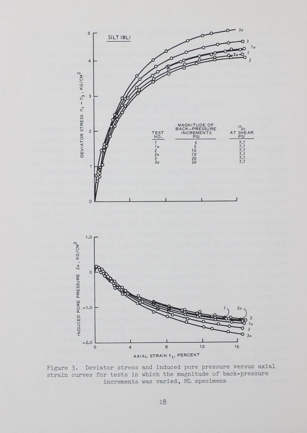
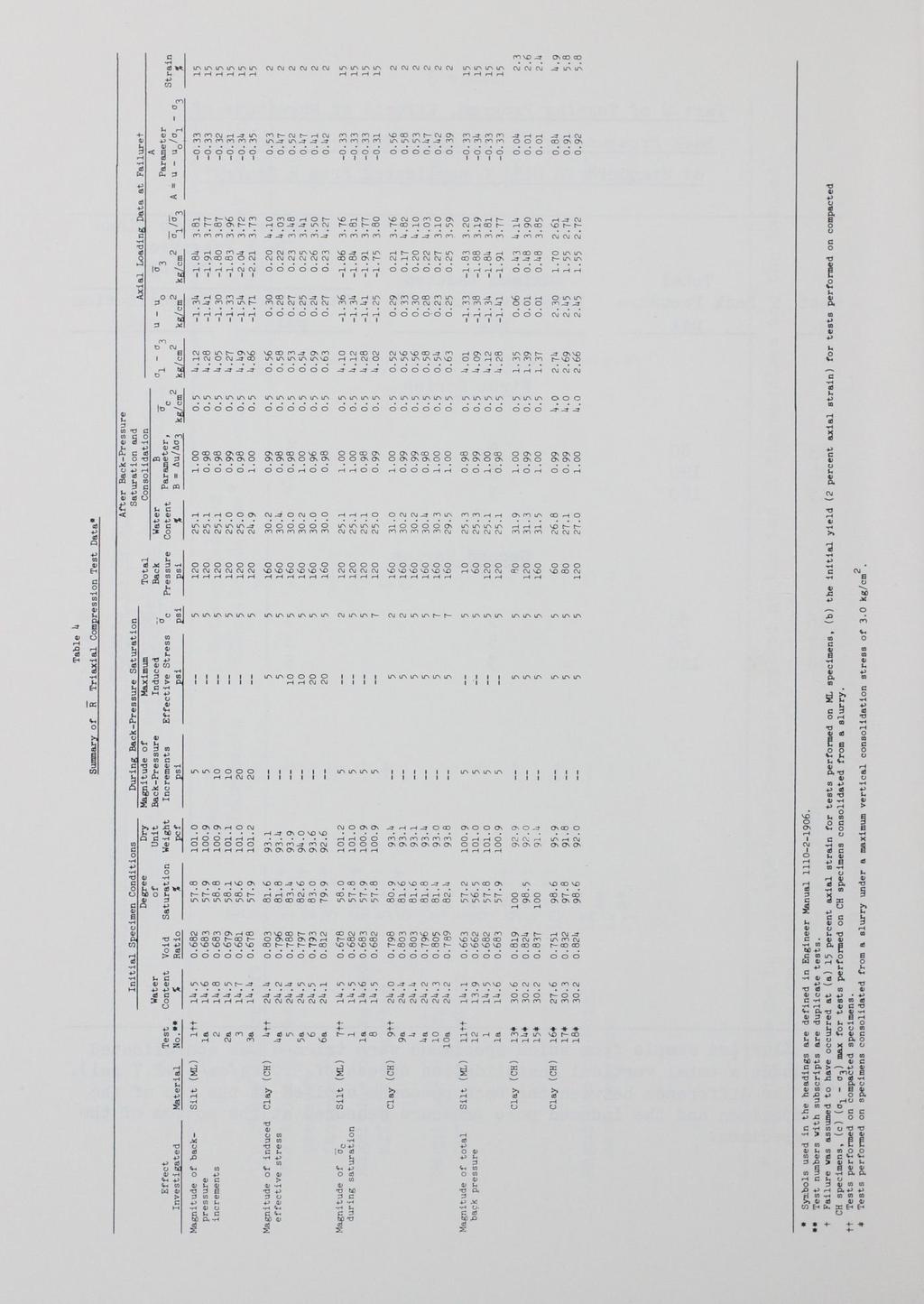
20 PART III : TEST RESULTS AND DISCUSSION 18. Results of the 26 R triaxial tests performed on the to soils are summarized in Table 4 and are presented graphially in Figures 3 through 19. aording to the variables investigated. The tests are grouped in the table and figures Effets of Magnitude of Bak- Pressure Inrements, ML Material 19. Fi gure 3 presents deviator stress and indued pore pressure versus axial strai n urves for tests performed on ML speimens bak pressured using mode 2 to determine the effets of varying the magnitude of bak- pressure inrements from to 2 psi. While EM allos these magnitudes of bak-pressure inrements, it is quite poss i ble prestressing ould our if this magnitude exeeds the onsolidation stress. The effet of bak- pressure inrement magnitude on deviator stress and indued pore pressures at 1 perent strain are presented in Figure 4. These omparisons sho that inreasing the magnitude of bak- pressure inrements from to 1 psi had little effet on either deviator stresses or indued pore pressures. There as, hoever, a signifiant hange in both deviator stresses and indued pore pressures taken at 1 perent strain hen the magnitude of bak- pressure inrements as inreased from 1 to 2 psi. For this range, the deviator stresses at failure ere inreased by approximately 12 perent, and the orresponding indued pore pressures ere redued approximately 18 perent. Sine the onsolidation pressure at shear, a 3, as only. kg/m 2 ([.1 psi), the initial 2- psi bak- pressure inrements most likely prestressed the speimen signifiantly, ausing slightly loer ater ontents and orresponding higher strengths and loer lndued pore pressures. The relationship beteen deviator stresses at failure and f inal ater ontents for ML speimens given in Figure shos that the strength of ML speimens is very sensitive to small differenes in final ater ontent ith a. 1 perent differene ln final ater ontent, resulting in a.3-kg/m 2 differene in the 17
21
 a:")
22 SILT<ML) 3o 4 1o 1 2o 2 DEVIATOR STRESSES -X <( 1- z a: u Ill <( z 2 <( 1- (/) a: :> (/) (/) a: 1.. a:.. u 6 z z <( (/) (/) (/) a: (/) a: 1- <( > 1 1o 2 2o - INDUCED PORE PRESSURES o 3 3o -2L MAGN I TUDE OF BAC K - PRESSURE I N C REMENTS, PSI Figur e 4. Deviator stresses and indued pore pressures taken at 1 perent axial strain versus magnitude of bak- pressure i nrements, ML speimens, o 3 =. kg/m2 (7. 1 psi) 19

23 6.. SI LT (M L) N :::E u.... z - <{ a: (/) _j <{ -X <{ z u a: u. If)... <{ (/) (/) a: (/) a: <{ - > a 7a 2a L FINAL WATER CONTENT, PERCENT Figure. Deviator stress at 1 perent axial strain versus final ater ontent, ML speimens 2

24 deviator stress at failure. The pore- pressure parameter A versus magnitude of bak- pressure inrement plot given in Figure 6 shos that greater negative A values ere developed for the speimens saturated using 2- psi bak- pressure inrements. It may be noted that greater negative values of A ould also our for more dense speimens suh as might result from prestressing speimens during the satur ation proedure. Thus, the alloing of bak- pressure inrements in exess of a 3 ould ause prestressing. Effet of Magnitude of Effetive Stress Indued by Bak Pressure, CH Material 2. Plots of deviator stress and indued pore pressure versus axial strain for tests performed on CH material bak pressur e saturated us1ng mode 1 in hih the maximum differene beteen applied bak pressure and indued pore pressure measured at the base of the speimen as varied from to 2 psi are given in Figure 1. Sine the saturation apparatus alloed this differene to be ontrolled, it as hoped that results of these tests ould be used to determine the extent to hih speimens might be prestressed during saturation ithout s ignifiantly affeting test r esults. The stress- strain urves sho that in all ases deviator stresses inreased rapidly to an axial strain value of approximately 1 perent and then after either dereasing slightly or almost leveling off began to inrease gradually at strains of from 2 to 4 perent and ontinued to inrease until the end of the tests. (This inrease as probabl due to dilative tendenies ausing porepressure dereases and a orresponding inrease in strength. ) Sine this initial yield ould most likely reflet effets due to prestressing speimens during saturation, failure as assumed to have ourred at an axial strain value of 2 perent. Effets of indued effetive stresses ourring during saturation are shon in Figure 8, hih shos deviator stresses and indued pore pressures at failure versus the magnitude of the indued effetive stresses. As may be seen, deviator stresses ere relatively unhanged by effetive stresses up to 1 psi ; hoever, there as an inrease in deviator stress of 21

25 .6 SILT <MU.4... ('1') I - g ' ::l I... ::l. 2 II <{ z -<{ a:: (/)...J <{ - X <{ z l) a:: a. It) - <{ a:: <{ a:: <{ a l, l 2o 2 3 3o <{ L L L J MAGNITUDE OF BACK- PRESSURE INCREMENTS, PSI Figure 6. A parameter at 1 perent axial str ain versus magnitude of bak- pressure inrements, ML spe1mens, a 3 =. kg/m2 (7.1 psi) 22
.4 ::J 4 <J. 2 a:: ::J (/) (/) a:: 6 a.. a:: a.. u ::J z -.")
26 .8 CLAY (CH) N ::E u.6... C) ('11 b I 4o s So 6 b (/).4 (/) MAGNITUDE OF a3 AT a:: INDUCED EFFECTIVE 1- TEST STRESS SHEAR (/) NO. PSI PSI a:: o s 7. 7 s So > o L N ::E u... C).4 ::J 4 <J. 2 a:: ::J (/) (/) a:: 6 a.. a:: a.. u ::J z AX IA L ST R A IN : 1, P E RCENT Figure 7. Deviator stress and indued pore pressure versus axial strain urves for tests in hih the magnitude of effetive stresses indued by bak pressure as varied, CH speimens 6o So 23

27 L EFFECT IVE STRESS I N D U C ED BY BAC K PRESSU RE, K G/CM 2 Figure 8. Deviator stresses and indued pore pressures taken at 2 perent axial strai n versus magnitude of effetive stress indued by bak pressure, CH speimens, o 3 =. kg/m2 (7.1 psi) 24

28 approximately 13 perent hen the max1mum indued effetive stress as inreased from 1 to 2 psi. Indued pore pressure, on the other hand, dereased ith inreasing indued effetive stresses up to the maximum effetive stress of 2 psi. The derease in indued poreater pressure ourring beteen effetive stresses of and 1 psi as approximately 1 perent, hile that ourring beteen effetive stresses of 1 and 2 psi as approximately 6 perent. Values of deviator stresses at failure ranged f r om. 3 to. 63 kg/m 2, hile indued pore pressures varied f r om. 3 to. 24 kg/m 2. A parameter taken at failure Af in Figure 9 indiates that Af The relationship beteen the and indued effetive stresses g1ven dereases ith inreasing indued effetive stresses ith the greatest redution ourring beteen effetive stresses of 1 and 2 psi. Sine the onsolidation pressure at shear, o 3, as only. kg/m 2 (7. 1 psi), the initial 2- psi bak- pressure inrements most likely prestressed and aused overonsolidation of the speimens. Loer A values at failure also reflet a greater degree of overonsolidation, hene the inrease in strength noted for spe1mens saturated under a maximum indued effetive stress of 2 psi is attributed to overonsolidation ourring as a result of prestressing the speimens during saturation. exess of Thus, bak- pressure inrements in an ause detrimental prestressing. Effet of Magnitude of o During Saturation, CH and ML Materials 21. The extent to hih speimens may be prestressed during saturation also depends, of ourse, on the effetive onsolidation stress (hamber pressure minus bak pressure), o, ating during the satura tion proedure ith respet to during shear. Deviator stress and indued pore pressure versus axial strain urves for tests in hih o during saturation as varied from 2 to 1 psi are shon in Figures 1 and 11 (bak pressure as applied in - psi inrements for eah Plots of deviator stresses and indued pore pressures taken at ) failure (at an axial strain value of 1 perent) versus during saturation for the ML speimens given in Figure 12 sho that there as no 2

29 .8 CLAY <C H> t:f t t) -... :::l t - :::l II.4. z - a: (/)...J - X 1- z u a: a. N 1- a: 1- :E a: a a Sa 6a L L EFFECTIVE STRESS INDUCED BY BACK PRESSURE, KG/ CM 2 Figure 9. A parameter at 2 perent axial strain versus magnitude of effetive str ess indued by bak pressure, CH speimens 26
 (/') r a. r a. u :::> z -1. - 2. ----------L--------------------------- 4 8 12 16 AXIAL STRAIN t: 1, PERCENT 8 1 7 1o Figure 1.")
30 4. SILT (MU N u ' (!) :X: C"'l tj - tj (/') (/') r 1- (/') r 1- <t: - > DURING DURING TEST SATURATION SHEAR NO. PSI PSI o o O' L r.:::> (/') (/') r a. r a. u :::> z L AXIAL STRAIN t: 1, PERCENT o Figure 1. Deviator stress and indued pore pressure versus axial strain urves for tests in hih the magnitude of the effetive onsolidation str ess during saturation as varied, ML speimens 27
 V) a:: a_ a:: a_ u :::> z. 2 4, 4a 9 -.2 ------------------------------_.-------------------- 4 8 12 16 2 AXIAL STRAIN E 1, PERCENT Figure 11.")
31 .8 CLAY (CH) loa 4 1 N 9o u.6... (!) 9 (T') t> t> V). 4 V) a a:: 1- V) DURING TEST SATURATION NO. KG/CM 2 a:: o 2 4 >. 2 4a Oa L a:: :::> V) V) a:: a_ a:: a_ u :::> z. 2 4, 4a _ AXIAL STRAIN E 1, PERCENT Figure 11. Deviator stress and indued pore pressure strain urves for tests in hih the magnitude of the solidation stress during saturation as varied, CH versus axial effetive on-. spe1mens 28

32 Sl L T <M L> z <t :: 4... U') _J <t X <t... z 3 :: a.. - IS)... <t z 2 <t... U') :: ::> U') U') :: 1 a.. :: a.. ::> z z <t U') U') U')... U') :: -1 ::... <t > 7 7o. DE VIA T OR STRESSES 8 INDUCED PORE PRESSURES O DURING SATURATION, KG/ CM 2 Figure 12. Deviator stresses and indued pore pressures taken at 1 perent axial strain versus the magnitude of the effetive onsolidation stress during saturation, ML speimens, r 3 =. kg/m 2 (7. 1 psi) 1 29

33 signifiant effet on either deviator stresses or indued pore pressure due to varying r from 2 to 7 psi. The deviator stresses at failure ranged from 4. 2 to kg/m 2 and indued pore pressures at failure varied from to kg/m In the ase of CH speimens, Figure 13 shos that hen (J during saturation as varied from 2 to 7 psi, deviator stresses at failure (assumed to have ourred at an axial strain value of 2 perent) inreased, hile the orresponding indued pore pressures dereased. Based on average values taken at eah (J value, the deviator stress as inreased by approximately 7 perent and the indued pore pressure as redued by approximately 22 perent. Deviator stresses at failure for the CH speimens varied from. 2 to. 63 kg/ m 2, and the orresponding indued pore pressures ranged from. 34 to. 23 kg/m 2. The inrease in deviator stress (approximately 9 perent) and the redution in indued pore pressure (approximately 7 perent) ourring hen r as inreased from 2 to psi as insignifiant. (Engineer Manual * during saturation. ) Plots of states that versus (J (J should not exeed psi given in Figure 14 sho that hanged very little ith inreasing (J values for the ML speimens, thereby indiating no signifiant effet due to varying The urve for CH speimens (Figure 13), on the other hand, shos a rather substantial redution of approximately 3 perent ln Af (J values hen r as inreased from 2 to 7 psi, thus indiating a signifiant effet due to varying r during saturation. 23. The sensitivity of the CH speimens to varying (J during onsolidation is attributed to prestressing the speimens at the higher (J (J the values. Although r during shear as 7.1 psi and the maximum during onsolidation as 7. psi, the prestressing ourred during initial bak- pressure phases before the speimen as saturated. this stage, a bak- pressure inrement of psi as appli ed to the top of the speimen; hoever, the instantaneous pressure differential aross the speimen ould be psi, ausing the instantaneous * Engineer Manual , op. it. r At to be 12 psi 3

34 1.2..._ z..._ (/) 1. O::N ::::> u.8 W '- a:: a.. z - a:: - a....._ a:: (/) CLAY <CH) loa u...j.6 4a :::> 9a X z _ 9 z z u (/) a:: (/) (/) a...4 a:: N DEVIATOR STRESSES..._ (/) a:: 4..._ <t: - > 9a a loa INDU CED PORE PRESSURES L O DURING SATURATION, KG/ CM 2 Fi gure 13. Deviator stresses and indued pore pressures taken at 2 per ent axial strain versus the magnitude of the effetive onsolidation str ess during saturation, CH speimens 31
35 .8.6 9o o -;9; !..._ - -(T) b I - b... :I - :I II <( - a:: 1- <( a:: <(.. <( a 1 1a -.2 SILT <ML) 7 8 1, L i L O DURI N G SATURATION, KG / CM 2 Figure 14. A parameters for CH and ML speimens taken at 2 and 1 perent axial strain, respetively, versus the magnitude of the effetive onsolidation stress during saturation 32

36 (7 + psi). By this approah, the intermediate value of psi ould also lead to overstressing. The more permeable nature of the ML speimens probably minimized the instantaneous pressure differential and orresponding prestressing effet. 24. The folloing tabulation of Af and (r 1 - a 3 ) values for all tests on ompated CH speimens shos that effets due to varying a from 2 to 7 psi ere slightly greater than varying indued effetive stresses due to bak-pressure inrements from to 2 psi : Test No. Effetive Magnitude of Indued Consolidation Effetive Stress Pressure ps1 r, psi A Parameter at Failure Af Testing Variable - Magnitude of Indued Effetive Stress Deviator Stress at Failure (rl - 3)f kg/m 2 4 4a a 6 6a Testing Variable - Magnitude of Effetive Consolidation Stress 9 9a 4 4a 1 loa As may be seen, Af values for tests in hih r as varied ranged from. 38 to. 9, hile those for tests in hih indued effetive str esses ere varied, ranged from. 41 to. 3. note that the maximum hange in (r 1 - variables as.11 kg/m 2. It is of interest to a 3 )f ourring f or both testing Thus, the effet of both variables on (r 1 - a 3 )F as to produe a maximum hange in (r 1 - r 3 )f of approxlmately 18 perent. The greater effet of varying r on Af values 33

37 rather than varying indued effetive stesses is attributed to the fat that in varying a the magnitude of a is onsistently applied to the speimen for longer times and at higher atual hamber pressures. Conversely, in varying the indued effetive stress, only during the initial saturation stages is the maximum magnitude of indued effetive stress applied to the speimen. Hoever, as the speimen beomes saturated, the magnitude of indued effetive stress dereases, hene the maximum value of indued effetive stress is applied to the speimen for a shorter time period and at loer hamber pressures than hen varying a Effet of Magnitude of Total Bak Pressure 2. A differential vauum saturation proedure as developed to determine the effet of the magnitude of total bak pressures ranging as lo as 1 psi in tests performed on ML speimens. The proedure, developed to avoid signifiant prestressing of the speimen, onsists of initially de- airing the speimen by simultaneously inreasing the vauum ating on the top of the speimen and in the hamber, maintaining a small differene beteen them until a full vauum is applied to the speimen. De- aired ater is then alloed to flo through the speimen from bottom to top under a lo differential vauum head (approximately psi), thus filling the previously de- aired voids ith ater. The vauums applied to the top of the speimen and to the hamber are then sloly released, maintaining their initial differene until no vauum is ating ithin the hamber and a vauum equal to the initial differene is ating on the top of the speimen. This vauum is then dissipated, maintaining the initial differential onstant by simultaneously dereasing the vauum and inreasing the hamber pressure. The standard bak- pressure saturation proedure is then initiated. During the proedure, the differenti al vauum ating beteen the top and bottom of the speimen and the top of the speimen and the hamber is monitored ith differential pressure transduers, hih permits areful monitoring to avoid prestressing. Use of the differential vauum saturation 34

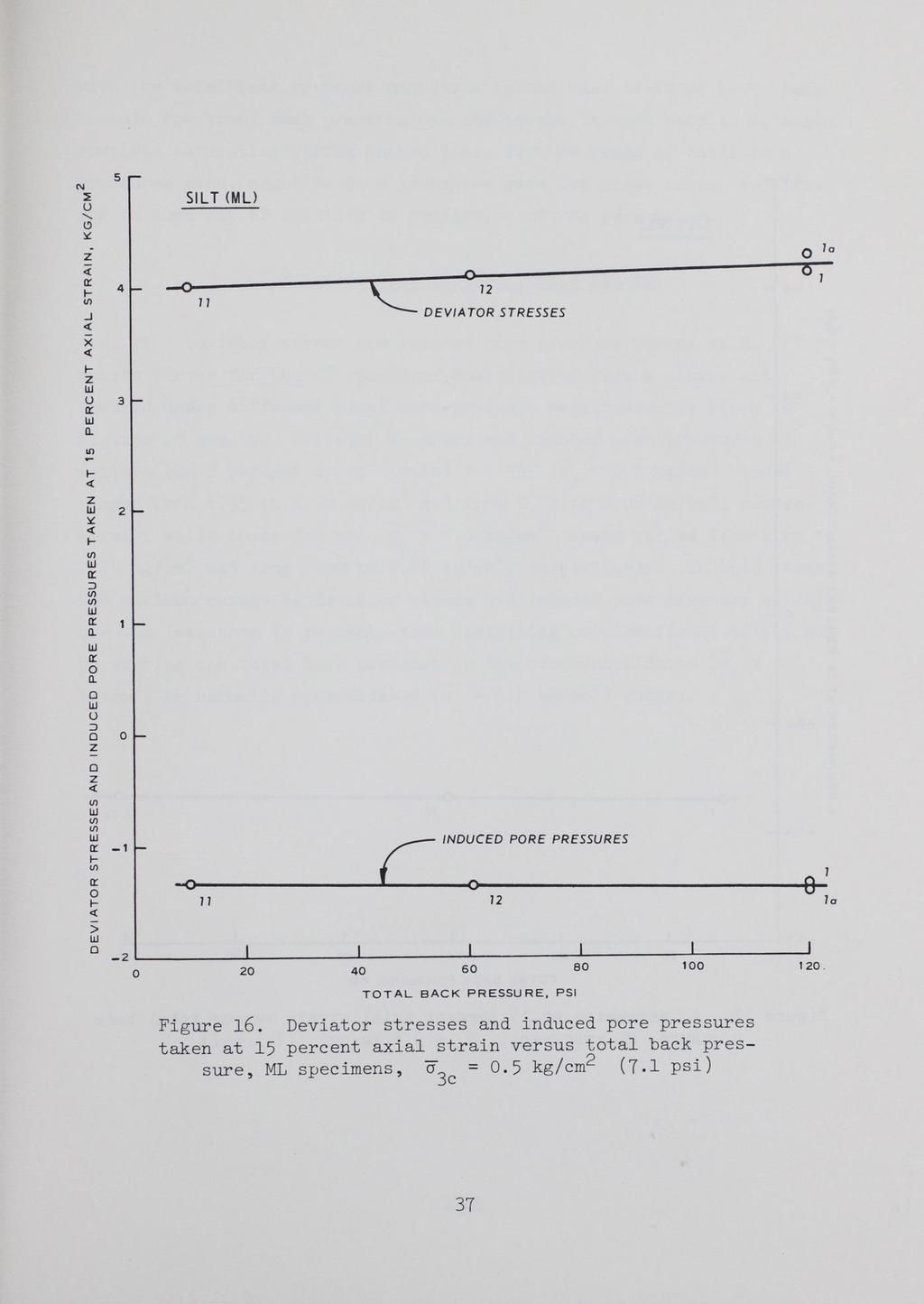
38 proedure an saturate speimens ith no signifiant effets due to prestressing and also has the advantage of enabling speimens to be saturated using bak pressures equal to field hydrostati onditions. The latter advantage ould, of ourse, eliminate the problem of high laboratory strengths resulting from the greater negative indued pore pressures in dilative speimens during shear assoiated ith the high bak pressures usually required for saturation, sine the expeted field hydrostati ondition ould be used as the bak pressure. An additional advantage of the vauum saturation proedure as applied to ohesionless soils is that the time for saturation is shorter, sine it is not neessary to ait for signifiant amounts of air to pass into solution in the pore ater under inreasing bak pressures. Time of saturation for the to tests in hih the differential vauum proedure as used (those having total bak pressures of 1 and 6 psi) as less than 2 hr. The differential vauum saturation proedure is outlined in Appendix C. 26. Figure 1 shos indued pore pressure and deviator stress versus axial strain urves for the tests performed on ML speimens in hih the total bak pressure as varied. As may be seen, both the deviator stress and indued pore- pressure urves indiate little effet due to varying the magnitude of total bak pressure. Deviator stresses and indued pore pressures taken at 1 perent axial strain and plotted against total bak pressure shon in Figure 16 indiate that there may be a slight trend for deviator stresses to inrease and for indued pore pressures to derease ith inreasing bak pressures ; hoever, the hanges in both ases are insignifiant (less than 9 perent). The A parameter versus total bak pressure plot shon in Figure 17 also indiates no signifiant hange in A due to varying the total bak pressure, the average value of A being. 33. It should be emphasized that the f inding that varying the total magnitude of bak pressure had little effet on indued pore pr essures or strength should not be applied to other soils or to speimens of the standard ML material tested at higher dry unit eights or under loer onsolidation pressures. Negative indued pore pressures and, hene, deviator stresses did not vary 3
 (/) a:: a.. a:: -1. a.. u :::> z - -2. 4 8 12 16 11 1 12 1o AXIAL STRAIN t: 1, PERCENT Figure 1.")
39 1o 1 4 SI LT(MU N u 3 '- t!) :::.::: ("t') t) - t) TOTAL (/) 2 BACK (/) TEST PRESSURE Ck: NO. PSI 1- (/) 11 1 a:: o 12 <( > N u '- t!) -:.::: 1. ::I <l a:: :::> (/) (/) a:: a.. a:: -1. a.. u :::> z o AXIAL STRAIN t: 1, PERCENT Figure 1. strain urves for tests in hih the magnitude of the total bak pressure as varied, ML spe1mens, o =. kg/m2 3 Deviator stress and indued pore pressure versus axial 36
40

41 .8 SILT(MU... -(T) -... :I... :;) II.6.4 <{ z - -<{ a:.2 1- (/)...J <{ - X <{ 1- z u a: Q. -It) 1- <{ a: 1- UJ <{ a: <{ Q. -.2 <{ J. J TOTAL BACK PRESSURE, PSI Figure 17. A parameter at 1 perent axial strain versus total bak pressure, ML speimens, a =. kg/m 2 (7. 1 psi) 38

42 ith the total bak pressure magnitude in the ase of t hese tests only beause the total bak pressure as suffiient in eah ase to maintain omplete saturation during shear ; i.e., for the range of total bak pressures used, negative pore pressures ere not great enough to allo air to ome out of solution or avitation of the pore ater. CH Material Consolidated from a Slurry 27. Deviator stress and indued pore pressure versus axial str ain urves for the CH speimens onsolidated from a slurry and sheared under different total bak- pressure magnitudes are given in Figures 18 and 19. Deviator stresses and indued pore pressures at failure (at 2 perent axial strain) for the o -. kg/m 2 tests 2 2 ranged from 1. 3 to kg/em and from. 1 to. 6 kg/em, respetively, hile those for the o - 4. kg/m 2 tests varied from to kg/em and from 2. 3 to 2. 4 kg/m 2, respetively. In both ases, the max1mum hange in deviator stress and indued pore pressure at failure as less than 1 perent, thus indiating no signifiant effet due to varying the total bak pressure in the overonsolidated 2-2 kg/em ) or normally onsolidated (o = 4. kg/em ) ranges. (o =. 39
 (f) r a_ r a_ 13 u ::J 1 z 14 -.2 4 8 12 16 2 A X I A L STRAIN. 1, PERCENT Figure 18.")
43 2. CLAY (CH > O = 7. PSI N u ('I") 1 I - 13 (f) 1. (f) r r (f) r TOT AL B ACK r T EST P R ESSU RE <( N O. PSI - > L _j N u....4 ::I <l. 2 r ::J (f) (f) r a_ r a_ 13 u ::J 1 z A X I A L STRAIN. 1, PERCENT Figure 18. Deviator stress and indued pore pressure versus axial strain urves for tests 13, 14, and 1 in hih the magnitude of the total bak pressure as varied, CH speimens onsolidated from a slurry 4o
 ::l <l a:: ::::> (/') (/') a:: a.")
44 4 CLAY (C H> O = 6.9 PSI N u 3... (!) b b (Y') I - 18 (/') 2 (/') a:: r- (/') TOTAL BACK a:: TEST PRESSURE NO. PSI r- <{ 16-6 > o L L L N u "" (!) ::l <l a:: ::::> (/') (/') a:: a. a:: a. u ::::> z AXIAL STRAIN f:, PERCENT Figure 19. Deviator stress and indued pore pressure versus axial strain urves for tests 16, 17, and 18 in hih the magnitude of the total bak pressure as varied, CH speimens onsolidated from a slurry 41
 and Viksburg bukshot (CH), the folloing onlusions have been made. Compated Speimens, r - 7.1 psi 2 (.")
45 PART IV: CONCLUSIONS AND RECOMMENDATIONS 28. Based on the results of this program of R triaxial ompression tests onduted on Viksburg loess (ML) and Viksburg bukshot (CH), the folloing onlusions have been made. Compated Speimens, r psi 2 (. kg/em) 29. For ompated speimens, onlusions are : a. b. a psi 2 (. kg/em), the Prestressing (overonsolidation) of triaxial tests speimens an our, resulting in testing errors, any time the magnitude of bak- pressure inrements or indued effetive stress (the differene beteen the applied bak pressure and the indued pore pressure measured at the speimen base) exeeds the effetive onfining stress at shear, r 3. In this ontext, a literal interpretation of the arbitrary Engineer Manual * statement, "The size of eah inrement (of bak pressure) might be, 1, or even 2 psi, depending on the ompressibility of the soil speimen and magnitude of the desired onsolidation pressure," an lead to prestressing and assoiated errors. It is reommended that the more restritive statement, "the size of eah bak- pressure inrement should not exeed the magnitude of the desired effetive onsolidation pressure, r3, unless preautions are taken to monitor the indued effetive stress and prevent this stress from exeeding the desir ed effetive onfining pressure," be used. Prestressing of triaxial test speimens an our if effetive onsolidation stresses during saturation, r, are greater than the effetive onfining stress at shear, o3. In this ontext, a literal interpretation of the Engineer Manual * guideline, "... the differene beteen the hamber pressure and bak pressure should not exeed psi during the saturation phase," may be too onservative or onversely lead to testing errors depending upon the magnitude of o 3 during shear. It is reommended that the statements, "... the differene beteen the hamber pressure and bak pressure at the top of the speimen should not exeed the effetive onfining stress during shear, r3. It is suggested, but not * Engineer Manual , op. it. 42

46 required, that this differene not exeed psi hen r3 is greater than psi," be substituted as this guideline.. The magnitude of total bak pressure had no signifiant effet on test results of ML speimens here indued negative pore pressures are less than 22 psi. Hoever, Engineer Manual provides no guidane onerning seletion of peak strengths of dilative soils here negative indued pore pressures an reate exessively high strengths. d. The effet of prestressing aused by the magnitude of the effetive onsolidation stress during saturation (onlusion b) an have a greater effet than the magnitude of indued effetive stress (onlusion a) hen both magnitudes are the same. CH Speimens Consolidated from a Slurry, r- 7. and 6.9 psi (. and 4. kg/m2) 3. There is no signifiant effet on deviator stresses or indued pore pressures taken at failure due to varying the total bak pressure from 6 to 12 psi and from 8 to 16 psi on normally (; = 4. kg/m 2 ) and overonsolidated ( =. kg/m 2 ) CH speimens, respetively, one solidated from a slurry under a maximum effetive vertial onsolidation 2 stress of 3. kg/em. Testing Equipment and Proedures 31. An automati bak- pressure saturation devie has been designed and fabriated that dupliates the proedure outlined in the laboratory soils testing manual (see Appendix A). The devie provides a satisfatory alternative means for bak- pressure saturating speimens hen used in the mode to ontrol the magnitude of the indued effetive stress during saturation. 32. A differential vauum saturation proedure has been developed that enables speimens of ohesion1ess soils to be saturated using bak pressures equal to f i eld hydrostati onditions. 33. An i nvestigation into the effets of using the differential vauum saturation proedure on dilative soils in hih avitation ill our under bak pressures equal to f ield hydrostati onditions is 43

47 needed. The purpose of this investigation should be to determine hether strength envelopes obtained from suh tests ould be used ln design analyses. Also, further testing should be onduted to determine the effet of varying the total time for saturation, sine thixotropi effets ere not studied in this investigation. 44

48 Table 1 Saturation Phase of R Triaxial Tests* Speimen Charateristi, Symbol or Apparatus 2 or Tehnigue Abbreviation 1 Largest bak- pressure 6U max 8.2 inrement, psi Smallest bak- pressure 6u min 1. inrement, psi Smallest effetive onsolidation tla min. pressure during bak pressur- ing, psi Shortest duration of bak- 6t min 12 s pressure inrement, min Total time for saturation, min t 2, 88- s 14, 4 Laboratory , , , ,18,76 1,68 2, 1,9 1,44 1,44 * Data taken from Misellaneous Paper 3-813, op. it. three soil types (ML, CL, and CH). Data represent range in differenes for all tests performed on the

49 T:=tble 2 Part 1 of Testing Program, Ef fets of Bak- Pressure Saturation Tehniques in R Triaxial Tests on Compated Soils Bak- Pressure Maximum Indued Test Inrements Effetive Stress* During Saturation To Study Effet of : No. ps1 psi psi Magnitude of bak- l **, t pressure 2**, t 1 inrements 3**, t 2 Magnitude of indued 4f,tt effetive stress t,tt 1 6t,tt 2 Magnitude of O 7** 2 during saturation 1** s ** 7 9t,tt 2 4t,tt 1 t,tt 7 Magnitude of total 11** bak pressure 12** 1 ** Total Bak Pressure ps * The differene beteen the bak pressure applied at the top of the spe1men and the indued pore pressure measured at the bottom of the speimen. ** Tests performed on ML speimens. t Dupliate tests ere performed. tt Tests performed on CH speimens.

50 Table 3 Part 2 of Testing Program, Effets of Magnitude of Bak Pressure in R Triaxial Tests on Speimens of Standard CH Soil Consolidated From a Slurry* Test No. Total Bak Pressure psi Maximum Indued Effetive Stress**. psl Chamber Pressure Minus Bak Pressure, a, During Saturation Consolidation psl psi First Series Seond Series * Slurried sample from hih speimens ere trimmed as onsolidated under a total vertial onsolidation stress of 3. kg/m2 (42. 7 psi). ** The differene beteen the bak pressure applied at the top of the speimen and the indued pore pressure measured at the bottom of the speimen.
51

52 APPENDIX A: BACK- PRESSURE SATURATION PROCEDURE SPECIFIED IN ENGINEER MANUAL The bak- pressure saturation proedure shall onsist of the folloing steps : a. Step 1. Estimate the magnitude of the required bak pressure by referene to Figure Al or other theoretial , u = u [ 1-( 1-HJS 1 O O 1-( 1-H!Sf \+lt-'..., "'"'r WHERE u =REQUIRED BACt< PRESSURE (GAGEl u = A T MOSPHERIC PRESSURE ( ABSOLUTE) = 14.7 PSI A H =HENRY'S CONSTANT=.1 8 (FOR AIR DISSOLVED IN WATER A T 22 CJ u a: UJ 1-- S = INITIA L DEGREE OF SA TURATION, PERCENT D..... <. s OC. f =FINAL DEGREE OF SATURATION, PERCENT z,_ AFTER LOWE ANO JOHNSON o e o "" r v.. r. a:.,_,.::: u. (' UJ UJ a: C) UJ..J > z r r so R EQUIRED B ACt< P R ESSUR E, U PSIG Figure Al. Bak pressure required to attain various degrees of saturation relations. Speimens should be ompletely saturated before any appreiable onsolidation is permi tted, for ease and uniformity of saturation as ell as to allo volume hanges during onsolidation to be measured ith the burette; therefore, the differene beteen the hamber pressure and the bak pressure should not exeed psi dur ing the saturation phase. To insure that a speimen is not pr estressed during the satur ation phase, the bak pressure must be applied in small inrements, ith adequate time beteen i nr ements to permit equali zation of pore-ater pr essure throughout the speimen. b. St ep 2. Wi th all valves losed, adjust the pressure regulators to a hamber pressure of about 7 psi and a Al
 to apply the bak pressure through DIAL INDICATOR p AXIAL LOAD WATER SUPPLY (OPTIONAL) FOR")
53 bak pressure of about 2 psi. Reord these pressures on the data sheet. No open valve A to apply the preset pressure to the hamber fluid and simultaneously open valve F (Fi gure A2) to apply the bak pressure through DIAL INDICATOR p AXIAL LOAD WATER SUPPLY (OPTIONAL) FOR DEAIRING LINES AND FOR SEEPAGE SATURATION OF SPECIMENS. BACK PRESSURE GAGE DIFFERENTIAL PRESSURE GAGE (OPTIONAL) :: CHAMBER PRESSURE GAGE. VALVE C VACUUM LINE (OPT/ONAU FOR DEAIRING LINES AND FOR SEEPAGE SATURATION VALVE K I, I CHAMBER PRESSURE RESERVOIR BACK PRESSURE RESERVOIR CALIBRATED BURETTE _..-- BACK PRESSURE REGULATOR VALVED VALVE G VALVE E VALVE F CHAMBER PRESSURE REGULATOR AIR PRESSURE LINE ELECTRICAL PRESSURE TRANSDUCER OR ACCEPTABLE NO-FLOW PORE PRESSURE MEASURING SYSTEM Figure A2. Shemati diagram apparatus for of typial triaxial ompression R and S tests the speimen ap. Immediately open valve G and read and reord the pore pressure at the speimen base. When the measured pore pressure beomes essentially onstant, lose valves F and G and reord the burette reading. If an eletrial pressure transduer is used to measure the pore pressure, valve G may be safely left open during the entire saturation proedure.. Step 3. Using the tehnique desribed in step 2, inrease the hamber pressure and the bak pressure in inrements, maintaining the bak pressure at about psi less than the hamber pressure. The size of eah inrement might be, 1, or even 2 psi, depending on the ompressibility of the soil speimen and the magnitude of the desired onsolidation pressure. Open valve G and measure the pore pressure at the base immediately upon appliation of eah inrement of bak pressure and observe the pore pressure until it beomes essentially onstant. The time required for stabilization of the pore pressure may range from a fe minutes to several hours, depending on the permeability of the soil. Continue adding inrements of hamber A2

54 d. pressure and bak pressure until, under any inrement, the pore- pressure reading equals the applied bak pressure immediately upon opening valve G. Step 4. Verify the ompleteness of saturation by losing valve F and inreasing the hamber pressure by about psi. The speimen shall not be onsidered ompletely saturated unless the inrease in pore pressure immediately equals the inrease in hamber pressure. A3

55 APPENDIX B: OPERATION OF AUTOMATIC BACK- PRESSURE SATURATION APPARATUS AND PRESSURE CONTROL SYSTEM 1. The folloing proedures for saturating speimens are referened to Figure Bl. Controlled Magnitude of Effetive Stress Indued by Bak- Pressure Proedure 2. Follo these steps : a. b.. d. e. f. De- air the portion of the system ontaining differential pressure transduer No. 1 by applying a vauum through valve I. Valves B, C, and E should be open and valves A, D, F, and J should be losed. Burette No. 1 should ontain suffiient de- aired ater to replae air removed from the system duri ng this proess. Flush the lines to the speimen ap and base ith de- aired ater. Valves B, C, F, and either valve A or D should be open to burette No. 2, hih should ontain suffiient deaired ater to aomplish the operation. (Valve D should be opened to de- air the line to the speimen ap. Valve A should be opened to de- air the line to the speimen base.) Valve E should be losed and valves I and J should be open. Close valves A and D and refill burette No. 2 ith suffiient de- aired ater to saturate the speimen and then adjust differential pressure transduer No. 1 to read zero using the proper ontrol on the paer onsole. Set the upper and loer limits for the differential pressure beteen the top and bottom of the speimen (the indued effetive stress) to be used during automati saturation by adjusting the appropriate ontrols on the paer onsole. The loer limiting differential pressure should be higher than any possible pressure differene due to the head loss ourring as the ater level in the burette falls. Af ter plaing the speimen in the hamber, lose the throttle valve and adjust the bak- pressure regulator to the maximum desired bak pressure to be applied during the saturation proedure. The pressure may be read on the bakpressure gage. Apply the desired differene beteen the hamber and bak pressure, r, to the speimen using the spring ontrol on the spri ng- and/or air- ontrolled pressure regulator. The pressure may be read on the differential pressure gage. Open valve G after the pressure has been set. Bl

56 .--. CHAMBER B URE TTE lu G A / T RIAXI A L 't' H { CHAMBER SOIL SPECIM EN DIFFERENTIAL PRESSURE TRANSDUCER NO. 1 DI FFERENTIA L PRESSURE GAGE VENT BURETT ES l... \. t I J /: _...,,).,.L SPRING- AND/OR AIR LOADED REGULA TOR _!SWI T CH "" j I :..... _ll : PRESSURE SOLENOID VALVE B I-THROTTLE DIFFERENTIAL PRESSURE TRANSDUCER NO.2 _,VALVE ' BACK " id " TRANSDUCER RE A DOUT ELECTRONIC PRESSURE PACER 1 ( SOLENOID VALVE A - / -1 PRESSURE RESERVOIR \..) B ACK - P R ESSURE G A GE B A CK PRESSUR E REGULATOR COM PRESSED AIR SUPPLY - ' Ill..... I "''I.A. L.,. tt.. "' "' "' Figure Bl. Shemati diagram of the bak pressure saturation apparatus and pressure ontrol

57 Close valves B, C, and J and open valves A and D. Automati saturation may no be initiated by sithing the " start" ontrol on the pressure paer for the ontrolled magnitude of indued effetive stress proedure and by opening the throttle valve, thus alloing pressure applied by the bak-pressure regulator aess to the speimen (through burette No. 2), the spring- and/or air- loaded regulator, and differential pressure transduer No. 1. When the pes sure transduer indiates the maximum desired indued stress has been developed, solenoid valve A loses (solenoid valve B remains open during this partiular saturation proedure) and ill not open again until the transduer indiates that the indued stress has been redued to the desired loer limit, hereupon the proess is repeated. This operation ontinues until the total desired bak pressure has been applied to the speimen. The saturation proedure has been ompleted hen the differential pressure reading for transduer No. 1 indiates that the indued effetive stress is less than the preset loer limiting value used to open solenoid valve A to apply an additional inrement of bak pressure. (Solenoid valve A ill be open at this stage and the total desired bak pressure ill be ating on the speimen. ) h. When the differential pressure reading for transduer No. 1 indiates an equilibrium ondition ithin the speimen under the total bak pressure, a B value determination may be made by losing valves B and G, inreasing the hamber pressure by 1 psi using the spring ontrol on the spring- and/or air- loaded pressure regulator, and then opening valve G and observing the pore- pressure response using transduer No. 1. If the speimen is not saturated even though the desired bak pressure has been applied, simply inrease the bak pressure using the bak-pressure regulator and the saturation sequene ill automatially resume. It may be neessary to inrease the pressure several times before the B hek indiates omplete saturation. Controlled Magnitude of Bak- Pressure Inrement Proedure 3. This proedure is idential to the preeding proedure exept for steps d and g. Components of the apparatus not used in the preeding proedure but used for this mode of operation are differential pressure transduer No. 2, solenoid valve B, and the pressure sith (see Figure Bl). B3

58 Step d 4. Set the desired magnitude for the bak- pressure inrements and the loer limiting value for the indued effetive stress using the proper ontrols on the paer onsole. Next, set the pressure sith so that it ill provide a signal to open both solenoid valves hen the total desired bak pressure has been reahed. Step g. Close valves B, C, and J and open valves A and D. Automati saturation may no be initiated by sithing the "start" ontrol on the pressure paer onsole for the ontrolled magnitude of bak- pressure inrement proedure and opening the throttle valve. When the reading for pressure transduer No. 2 indiates the desired magnitude of the bak- pressure inrement, solenoid valve B opens and solenoid valve A loses, thus plaing the pressure inrement into the system ating on the speimen. When the loer limiting indued effetive stress i s sensed by transduer No. 1, solenoid valve A opens and solenoid valve B loses, thus initiating another yle of the proedure. This operation ontinues until the pressure sith senses that the total desired bak pressure ls ating on the speimen, hereupon both solenoid valves are sithed to their open positions. B4

59 APPENDIX C: DIFFERENTIAL VACUUM SATURATION PROCEDURE 1. The folloing proedure is referened to Figure Cl. a. De- air the system ontaining the differential pressure transduer by applying a vauum through valve J, using regulator No. 2. Valves B and E should be open and valves C and I should be losed. Burette No. 1 should ontain suffiient de- aired ater to replae air removed from the system during this operation. b. Flush the line to the speimen base ith de- aired ater from burette No. 1. Valves A, B, E, and I should be open and valve C should be losed.. Close valve A and refill burette No. 1 ith suffiient deaired ater to saturate the speimen plus an additional amount equal to approximately 1 perent of the speimen volume. Then adjust the differential pressure transduer to read zero. d. Reapply a regulator ing valve e. vauum No. 2. J hen to burette No. 1 through valve J, using Lok the vauum into the system by losthe vauum gage indiates a high vauum. Remove any ater in the system to the top of the speimen by applying a small pressure to burette No. 2, using regulator No. 2. Valves F and D should be open and valves C and J should be losed. f. After plaing the speimen in the hamber on the previously saturated base and onneting the line to the ap (hih should ontain a dry porous stone), de- air the speimen by first applying a partial vauum of psi to the top of the speimen through burette No. 2, using regulator No. 2. The partial vauum may be read on the differential vauum gage, valve B should be losed, and valves A, D, and F should be open during this operation. & When the differential pressure transduer indiates an equilibrium ondition under the - psi partial vauum (a reading of zero), sloly inrease the partial vauums ating on the top of the speimen and the hamber maintaining the - - psi reading on the differential vauum gage, using regulators 1 and 2 until a full vauum is ating on the speimen. The differential pressure transduer reading should not indiate an i ndued effetive stress greater than 2 psi during this operation. When the differential pressure transduer indiates an equilibrium ondition, a full vauum ill be ating ithin the speimen and the e f fetive onfining pressure ill be psi. h. After aiting approximately 1 min or until all of the Cl
j;)l \"\"'--- 2 ( ) '-.")
60 PRESSURE OR VACUUM REGULATOR NO. 1 COM P RESSED A I R SUPPLY.-'- CHAMBER BURETTE H SOIL S P ECIMEN BURETTES VENT ' \ I DI FFERENTI A L PRESSURE O R V A CUUM GA GE V A CUUM SOURC E u-j -r , ")j;)l ""'--- 2 ( ) '-...,) BACK PRESSURE GAGE PRESSURE OR VAC U U M REGULATOR NO. 2 1\) -,- T E D ' ' "'' D l FFERENTIAL PRESSURE TRAN SDU C ER,,., «<...A J READ- I - OUT Figure Cl. Shemati diagram of the differential vauum saturation apparatus and pr essure ontrol system

61 i. remaining air in the speimen is removed, open valve B and then sloly open valve I, thus alloing de- aired ater in burette No. 1 to enter the bottom of the speimen under a negative pressure gradient. The gradient under hih ater flos into the speimen should not exeed - 2 psi and may be measured by the differential pressure transduer. It may be ontrolled by opening and losing valves I and J. Valve I should be opened to inrease the gradient, and valve J should be opened to derease the gradient. When ater appears at the bottom of burette No. 2, ontinue to allo ater to flo through the speimen under the ontrolled gradient until approximately 1 has entered the burette. Apparent air bubbles in the line to the top of the speimen may be due to avitation of the ater. i Close valve B and sloly release the vauums ating on the top of the speimen and the hamber, using regulators 1 and 2, maintaining the - - psi reading on the differential k. vauum gage and not alloing the differential pressure transduer reading to exeed - 2 psi. At the end of this operation, there should be no pressure on the hamber and - psi ating on top of the speimen. After the differential pressure transduer indiates an equilibrium ondition, simultaneously redue the - - psi partial vauum ating on the top of the speimen and inrease the hamber pressure to psi, using regulators 1 and 2. The hamber pressure may be read on the differential pressure gage. 1. The bak pressure ating on the speimen pore ater may no be inreased to the expeted field hydrostati ondition by opening valve K and inreasing the pressures applied by regulators 1 and 2, maintaining the - psi differential gage reading until the desired bak pressure is read on the bakpressure gage. The differential pressure transduer reading should not exeed 2 psi during this operation. m. After the differential pressure transduer reading one again indiates an equilibrium ondition, a determination of the pore- ater pressure parameter B may be made, and then onsolidation and shear of the speimen may proeed in the usual manner. C3
Comparison of the South Dakota Road Profiler with Other Rut Measurement Methods
 TRANSPORTATION RESEARCH RECORD 1311 Comparison of the South Dakota Road Profiler ith Other Rut Measurement Methods ]AMES B. DuBosE During the fall of 1989, the Illinois Department of Transportation ompleted
Dynamic Modeling of the Water Balance in the Cathode Gas Diffusion Layer of Polymer Electrolyte Fuel Cells
 Dynami Modeling of the Water Balane in the Cathode Gas Diffusion Layer of Polymer Eletrolyte Fuel Cells D. Fofana, K. Agbossou, Y. Dubé, J. Hamelin This doument appeared in Detlef Stolten, Thomas Grube
Stabilized Fly Ash Base
 8 TRANSPORTATION RESEARCH RECORD 144 Performane Evaluation of a Cement Stabilied Fly Ash Base. H. GRAY, E. TONS, AND T. R. THIRUVENGADAM The performane of a ompated, aggregate-free, ement-stabilied fly
Standard Test Method for Consolidated Undrained Triaxial Compression Test for Cohesive Soils 1
 Designation: D 4767 02 Standard Test Method for Consolidated Undrained Triaxial Compression Test for Cohesive Soils 1 This standard is issued under the fixed designation D 4767; the number immediately
11/ This paper not to be cited without prior reference to the author. I'
 / 11/ This paper not to be ited without prior referene to the author. I' International Counil for the Exploration of the Sea C. M. 197 2/H : 3 0 Pelagi Fish (N) Committee THE EFFECTS OF REGULATIONS OF
APPENDICES STRANDJACK WEDGES Friction coefficients, micro slip and handling
 APPENDICES STRANDJACK WEDGES Frition oeffiients, miro slip and handling Report nr. DCT 2005-78 By: H.G.M.R. van Hoof Idnr : 501326 20 November, 2005 Researh strand jak wedges Appendies By H.G.M.R. van
76.111/1. BUD: Flanged three-way valves, PN 6. Sauter Components
 76.111/1 BUD: Flanged three-way valves, PN 6 ow energy effiieny is improved urate ontrol with high reliability. reas of appliation Continuous ontrol of old/hot water and air in losed networks 1) and flow
Investigation on the Vortex Thermal Separation in a Vortex Tube Refrigerator
 doi: 1.236/sieneasia13-1874.2.31.2 SieneAsia 31 (2): 2-223 Investigation on the Vortex Thermal Separation in a Vortex Tube Refrigerator Pongjet Promvonge* and Smith Eiamsa-ard Department of Mehanial Engineering,
The following excerpt are pages from the North American Product Technical Guide, Volume 2: Anchor Fastening, Edition 16.
 The following exerpt are pages from the North Amerian Produt Tehnial Guide, Volume 2: Anhor Fastening, Edition 16. Please refer to the publiation in its entirety for omplete details on this produt inluding
The following excerpt are pages from the North American Product Technical Guide, Volume 2: Anchor Fastening, Edition 16.1.
 The following exerpt are pages from the North Amerian Produt Tehnial Guide, Volume 2: Anhor Fastening, Edition 16.1. Please refer to the publiation in its entirety for omplete details on this produt inluding
EMPLOYER SAMPLE PROCEDURES FOR HEAT ILLNESS PREVENTION
 EMPLOYER SAMPLE PROCEDURES FOR HEAT ILLNESS PREVENTION FEB 2010 California Employers with any outdoor plaes of employment must omply with the Heat Illness Prevention Standard T8 CCR 3395. These proedures
Rules of Hockey5s including explanations
 Rules of Hokey5s inluding explanations Effetive from 1 January 2015 (updated 18 May 2015) Copyright FIH 2015 The International Hokey Federation Rue du Valentin 61 CH 1004, Lausanne Switzerland Telephone:
Analysis of a Twin Screw Expander for ORC Systems using Computational Fluid Dynamics with a Real Gas Model
 Purdue University Purdue e-pubs International Compressor Engineering Conferene Shool of Mehanial Engineering 2014 Analysis of a Twin Srew Expander for ORC Systems using Computational Fluid Dynamis with
Rules of Hockey5 including explanations
 Rules of Hokey5 inluding explanations Effetive from 1 September 2012 Copyright FIH 2012 The International Hokey Federation Rue du Valentin 61 CH 1004, Lausanne Switzerland Telephone: ++41 21 641 0606 Fax:
product manual HM-4140, HM-4150, HM-4160 HM-4160A HM-4150 Humboldt FlexPanels
 12.09 product manual HM-4140, HM-4150, HM-4160 HM-4160A HM-4150 Humboldt FlexPanels Introduction: This manual covers the installation and operation of Humboldt FlexPanels for Triaxial and Permeability
BKR: 3-way ball valve with female thread, PN 40
 Regulating valves, ombined with atuator CV5.60 en Produt Data Sheet BKR015...050 BKR: 3-way ball valve with female thread, PN 40 ow energy effiieny is improved Preision ontrol and working without losses
VKR: 2-way regulating ball valve with female thread, PN 40
 Produt data sheet 7.1 56.090 VKR: 2-way regulating ball valve with female thread, PN 40 ow energy effiieny is improved Effiieny means preise ontrol and working with minimum leakage Features 2-way regulating
BKTA: 3-way change-over ball valve (T) with male thread, PN 40
 with male thread, PN 40") BKTA: 3-way hange-over ball valve (T) with male thread, PN 40 ow energy effiieny is improved Effiieny means preise hangeover with minimum leakage Features 3-way hange-over ball valve with T-bore for use
BKTA: 3-way hange-over ball valve (T) with male thread, PN 40 ow energy effiieny is improved Effiieny means preise hangeover with minimum leakage Features 3-way hange-over ball valve with T-bore for use
55.109/1. BUT: Three-way unit valve, PN 16. Sauter Components
 55.109/1 UT: Three-way unit valve, PN 16 How energy effiieny is improved Linear mixture and no leak losses in the ontrol passage for energy-effiient regulators. reas of appliation Regulating valve for
BKR: 3-way regulating ball valve with female thread, PN 40
 Produt data sheet 5.1 56.091 BKR: 3-way regulating ball valve with female thread, PN 40 ow energy effiieny is improved Effiieny means preise ontrol and working with minimum leakage Features 3-way regulating
15 March 1983 ERRATUM
 DEPARTMENT OF THE NAVY NAVY EXPERIMENTAL DIVING UNIT PANAMA ITY, FLORIDA 32407 15 Marh 1983 ERRATUM NEDU Report 1-83: omputer Algorithms Used in omputing the MK 15/16 onstant 0.7 ATA Oxygen Partial Pressure
Modelling the decrease in wave height over the shoreface due to slope-induced changes in bottom friction.
 Chapter : Modelling the derease in wave height over the shorefae due to slope-indued hanges in bottom frition. Abstrat Wave height-redution on the shorefae is partly indued by frition at the bottom. The
Vibration Related Testing for Hermetic Compressor Development
 Purdue University Purdue e-pubs International Compressor Engineering Conference School of Mechanical Engineering 1978 Vibration Related Testing for Hermetic Compressor Development J. P. Elson Follo this
WIND TUNNEL MEASUREMENT AND ASSESSMENT ON THE PEDESTRIAN WIND ENVIRONMENT A CASE STUDY OF JINYING HIGH RISE BUILDING IN TAIPEI, TAIWAN
 WIND TNNEL MEASREMENT AND ASSESSMENT ON THE PEDESTRIAN WIND ENVIRONMENT A CASE STDY OF JINYING HIGH RISE BILDING IN TAIPEI, TAIWAN Bao-Shi Shiau 1 and Ben-Jue Tsai 2 ABSTRACT In this paper, wind tunnel
Water )الطرق المائي( Hammer -3 rd Class Dr. Sataa A. F. Al-Bayati (08-09)
الطرق المائي( Hammer -3 rd Class Dr. Sataa A. F. Al-Bayati (08-09)") بسم هللا الرحمن الرحيم Water )الطرق المائي( Hammer -3 rd Class Dr. Sataa A. F. Al-Bayati (08-09) Water hammer is the momentary inrease in ressure, whih ours in a water system when there is a sudden hange
بسم هللا الرحمن الرحيم Water )الطرق المائي( Hammer -3 rd Class Dr. Sataa A. F. Al-Bayati (08-09) Water hammer is the momentary inrease in ressure, whih ours in a water system when there is a sudden hange
SPECIFICATION FOR REPEATED LOAD TRIAXIAL (RLT) TESTING FOR PAVEMENT MATERIALS
 TESTING FOR PAVEMENT MATERIALS") SPECIFICATION FOR REPEATED LOAD TRIAXIAL (RLT) TESTING FOR PAVEMENT MATERIALS 1. SCOPE This specification details the six (6) stage permanent strain Repeated Load Triaxial (RLT) test for unbound and modified
SPECIFICATION FOR REPEATED LOAD TRIAXIAL (RLT) TESTING FOR PAVEMENT MATERIALS 1. SCOPE This specification details the six (6) stage permanent strain Repeated Load Triaxial (RLT) test for unbound and modified
Rules of Beach Hockey including explanations
 Rules of Beah Hokey inluding explanations Effetive from 1 June 2016 (updated 31 May 2016) Copyright FIH 2016 The International Hokey Federation Rue du Valentin 61 CH 1004, Lausanne Switzerland Telephone:
Sauter Components
 55.009/1 U: Unit threeway valve, PN 1 How energy effiieny is improved inear mixing and no losses through leakage for energyeffiient ontrol. reas of appliation Control valve for ontrolling heating zones,
Vaccine Storage and Handling Guidelines
 Vaine Storage and Handling Guidelines Table of Contents 2 Introdution 3 Definitions 3 The Importane of the Cold Chain 3 Proteting Ontario s Vaine Supply 4 Maintaining Vaine Poteny and Minimizing Wastage
The following excerpt are pages from the North American Product Technical Guide, Volume 2: Anchor Fastening, Edition 17.
 The following exerpt are pages from the North Amerian Produt Tehnial Guide, Volume 2: Anhor Fastening, Edition 17. Please refer to the publiation in its entirety for omplete details on this produt inluding
BKR: 3-way ball valve with female thread, PN 40
 Regulating valves, ombined with atuator PDS 56.091 en Produt Data Sheet BKR015...050 BKR: 3-way ball valve with female thread, PN 40 ow energy effiieny is improved Preision ontrol and working without losses
BUL: 3-way unit valve, PN 16
 Produt data sheet 55.009 BU: 3-way unit valve, PN 16 Improving energy effiieny inear mixture and no loss through leakage in the ontrol passage for energy-effiient regulation Features Flat-sealing standard
Absorption Equilibrium and Kinetics for Ethylene-Ethane Separation with a Novel Solvent Introduction Experimental
 Absorption Equilibrium and Kinetis for Ethylene-Ethane Separation with a Novel Solvent Travis A. Reine, R. Brue Eldridge 2004 The University of Texas at Austin Prepared for Presentation at 2004 Annual
HURRICANE SANDY LIMITED REEVALUATION REPORT UNION BEACH, NEW JERSEY DRAFT ENGINEERING APPENDIX SUB APPENDIX E OVERTOPPING & FAILURE ANALYSIS
 HURRICANE SANDY LIMITED REEVALUATION REPORT UNION BEACH, NEW JERSEY DRAFT ENGINEERING APPENDIX SUB APPENDIX E OVERTOPPING & FAILURE ANALYSIS Revised 18 Feb 2015 1 OVERTOPPING & FAILURE ANALYSIS 1.0 Introdution
RESISTANCE OF COMPACTED ASPHALT MIXTURE TO MOISTURE INDUCED DAMAGE (Kansas Test Method KT-56)
") 5.9.56 RESISTANCE OF COMPACTED ASPHALT MIXTURE TO MOISTURE INDUCED DAMAGE (Kansas Test Method ) 1. SCOPE This test covers preparation of specimens and measurement of the change of tensile strength resulting
5.9.56 RESISTANCE OF COMPACTED ASPHALT MIXTURE TO MOISTURE INDUCED DAMAGE (Kansas Test Method ) 1. SCOPE This test covers preparation of specimens and measurement of the change of tensile strength resulting
Measurement System of Bubbly Flow Using Ultrasonic Velocity Profile Monitor and Video Data Processing Unit, (II)
") Journal of Nulear Siene and Tehnology SSN: 22-3131 (Print) 1881-1248 (Online) Journal homepage: http://www.tandfonline.om/loi/tnst2 Measurement System of Bubbly Flow Using Ultrasoni Veloity Profile Monitor
Journal of Nulear Siene and Tehnology SSN: 22-3131 (Print) 1881-1248 (Online) Journal homepage: http://www.tandfonline.om/loi/tnst2 Measurement System of Bubbly Flow Using Ultrasoni Veloity Profile Monitor
MECHANICAL INTEGRITY ASSESSMENT OF A LARGE HORIZONTAL NGL PRESSURE VESSEL: CASE STUDY
 Abstrat MECHANICAL INEGRIY ASSESSMEN OF A LARGE HORIZONAL NGL PRESSURE VESSEL: CASE SUDY A methodology for assessing the strutural integrity of a large horizontal NGL (Natural Gas Liquid) vessel has been
Design of a High Efficiency Scroll Wrap Profile for Alternative Refrigerant R410A
 Purdue University Purdue e-pubs International Compressor Engineering Conference School of Mechanical Engineering 1998 Design of a High Efficiency Scroll Wrap Profile for Alternative Refrigerant R410A J.
Statistical Mechanics of the Frequency Modulation of Sea Waves
 Statistial Mehanis of the Frequeny Modulation of Sea Waves Hiroshi Tomita and Takafumi Kawamura Ship Researh Institute, Shinkawa 6-8-, Mitaka, Tokyo 8-, Japan tomita@srimot.go.jp Abstrat. The longtime
Appendix A Preliminary SEMs
 Appendix A Preliminary SEMs SEM images of various gold tailings samples were taken as a preliminary investigation on the observable fabric and the possibilities with regards to using SEM images. These
General Technical Data and Calculations
 18 Bosh Rexroth AG R31EN 232 (26.4) General Produt Desription General Tehnial Data and Calulations Fores and load moments In Rexroth the running traks are arranged at a ompression angle of 45. This results
Operating Instructions Single/Dual Bourdon Tube Pressure Switches Type BS/BT/BX
 pproval data for Ex i swithes (BT and BX) pproval: II 1 G D Ex ia IIC T6 Ex ia D 20 T0 Operating Instrutions Single/Dual Bourdon Tube Pressure Swithes Type BS/BT/BX Certifiate no.: ISSeP08TEX016X Permissible
Operator s Manual S-492. Direct / Residual Shear Machine. Version 1.0. Durham Geo Slope Indicator 2175 West Park Court Stone Mountain, GA USA
 Direct / Residual Shear Machine S-492 ASTM D 3080 AASHTO T236 Operator s Manual Version 1.0 Durham Geo Slope Indicator 2175 West Park Court Stone Mountain, GA 30087 USA Phone: 800-837-0864 or +1.770.465.7557
Freeze-Thaw Effects and Gas Permeability of Utility Line Backfill
 1 Fred P. Hooper, 1 W. Allen Marr, 2 Ryan B. Drefus, 3 and Khalid Farrag 4 Freeze-Thaw Effects and Gas Permeability of Utility Line Backfill ABSTRACT: Backfill materials used in utility trenches must maintain
tel: fax: web:
 Tri-Flex 2 Five-Cell Permeability Test System For high volume commercial laboratory testing, the Tri-Flex 2 Five-Cell Permeability Test System offers the user the capabilities to test up to five samples
Air Cylinders Drive System Full Stroke Time & Stroke End Velocity
 Full Time & End Velocity Ho to Read the Graph This graph shos the full stroke time and stroke hen a cylinder drive system is composed of the As the graph shon belo, various load ratio and full stroke time
OP CHECKLIST FOR 1D CONSOLIDATION LABORATORY TEST
 Page 1 of 5 WORK INSTRUCTIONS FOR ENGINEERS NHB Compiled by : LSS Checked by : GSS Approved by : OP-3-31. CHECKLIST FOR 1D CONSOLIDATION LABORATORY TEST Page 2 of 5 31.0 CHECKLIST ITEMS *(refer to respective
The Optimal Control of a Periodic Adsorber:
 ., Natural Convetion in nonnewtonian Fluids Heated from Below, paper presented at First Paifi Chem. Eng. Congr. (1972). Samuels, M. R., Stability of a Fluid in a Long Horizontal, Retangular Cylinder Heated
Operating Instructions
 Operating life time Normal expeted servie life (expressed in the number of yles over the full adjustment range) is appr. 1 million for the pressure swith. This may be extended to 2.5 million yles max.
Implementing Actuated Signal-Controlled Intersection Capacity Analysis with Pedestrians
 Ipleenting Atuated Signal-Controlled Intersetion Capaity Analysis with Pedestrians DingXin Cheng, Zong Z. Tian, and Honghao Liu For an atuated signalized intersetion, pedestrian alls are likely to affet
RoboGolf (aka RoboPutting) Robofest 2016 Game
 Robofest 2016 Game") RooGolf (aka RooPutting) Roofest 201 Game 12-2-2015 V1.1 (Kik-off version. Offiial Version will e availale on Jan 8, 201) 4 3 2 1 a A. Game Synopsis Figure 1. RooGolf Playing Field (Jr. Division) There
RooGolf (aka RooPutting) Roofest 201 Game 12-2-2015 V1.1 (Kik-off version. Offiial Version will e availale on Jan 8, 201) 4 3 2 1 a A. Game Synopsis Figure 1. RooGolf Playing Field (Jr. Division) There
IN-PLACE DENSITY WAQTC FOP AASHTO T 209 (16)
") THEORETICAL MAXIMUM SPECIFIC GRAVITY (Gmm) AND DENSITY OF HOT MIX ASPHALT (HMA) PAVING MIXTURES FOP FOR AASHTO T 209 Scope This procedure covers the determination of the maximum specific gravity (Gmm)
THEORETICAL MAXIMUM SPECIFIC GRAVITY (Gmm) AND DENSITY OF HOT MIX ASPHALT (HMA) PAVING MIXTURES FOP FOR AASHTO T 209 Scope This procedure covers the determination of the maximum specific gravity (Gmm)
CHAPTER 5: VACUUM TEST WITH VERTICAL DRAINS
 CHAPTER 5: VACUUM TEST WITH VERTICAL DRAINS 5.1 Introduction Using surcharging as the sole soil consolidation mean can take a long time to reach the desired soil settlement. Soil consolidation using prefabricated
Development of Data Acquisition System for Consolidated Undrained Triaxial Test
 IOP Conference Series: Materials Science and Engineering PAPER OPEN ACCESS Development of Data Acquisition System for Consolidated Undrained Triaxial Test To cite this article: L M Lee et al 2016 IOP Conf.
Slow gas expansion in saturated natural porous media by gas injection and partitioning with nonaqueous
 MMaster University From the SeletedWorks of Sarah E Dikson 2008 Slow gas expansion in saturated natural porous media by gas injetion and partitioning with nonaqueous phase liquids Kevin G Mumford, Queen's
OPERATING INSTRUCTIONS
 OPERATING INSTRUCTIONS Tempe Pressure Cell June 1995 Fig. 1a 1400 Tempe Pressure Cells with 3cm cylinders and 6cm cylinders) mounted on the Tempe Cell Stand Fig. 1b Disassembled 1400 Tempe Pressure Cell
TEST FOR STABILOMETER VALUE OF BITUMINOUS MIXTURES
 Test Procedure for TEST FOR STABILOMETER VALUE OF BITUMINOUS MIXTURES TxDOT Designation: Tex-208-F Effective Date: February 2005 1. SCOPE 1.1 Use this test method to determine the Hveem stability value
Contents. LWN edition:
 Contents 7. Introdution... 7.- 7.. General Sizing Proedure... 7.- 7.. Seletion of the Sizing Standard... 7.-3 7. Engineering Support... 7.- 7.. List of Symbols... 7.- 7.. Properties of Gases... 7.- 7..3
Effect of Pavement/Shoulder Drop-Offs on Highway Safety
 Effet of Pavement/Shoulder Drop-Offs on Highway Safety John C. Glennon Transportation Consulting Engineer Overland Park, Kansas Drop-offs at the pavement/shoulder (or shoulder/roadside) edge have been
Oxygen permeation of La Sr CoO
 Solid State Ionis 98 (1997) 7 13 Oxygen permeation of La Sr CoO.3.7 3d 1 * C.H. Chen, H.J.M. Bouwmeester, R.H.E. van Doorn, H. Kruidhof, A.J. Burggraaf Laboratory for Inorgani Materials Siene, Faulty of
m. ANmYSIS OF RESULTS
 Aordingly, the U. S. Government retains a nonexlusive, royaltyfree liense to publish Effets of Vertial Aperture on Beam Lifetime at the Advaned Photon Soure ( A P S ) Storage Ring* Hana M. Bizek Advaned
Strength and Deformation Behavior of Soft Bangkok Clay
 Geotechnical Testing Journal, Vol. 26, No. 4 Paper ID GTJ8933_264 Available online at: www.astm.org T. H. Seah 1 and K. C. Lai 2 Strength and Deformation Behavior of Soft Bangkok Clay ABSTRACT: The influence
Hardware Triaxial and Consolidation Testing Systems Pressure Measurement and Control
 25 GDS Helpsheet Hardware Triaxial and Consolidation Testing Systems Pressure Measurement and Control World Leaders in Computer Controlled Testing Systems for Geotechnical Engineers and Geologists 1. Digital
Owners Manual. Durham Geo-Enterprises,Inc. Triaxial Panel Phone: Fax: Web site:
 Durham-Geo Enterprises Inc. S-500 TRIAXIAL/PERMEABILITY PANEL All information, illustrations and specifications in this manual are based on the latest information available at the time of publication.
ASPHALT WAQTC FOP AASHTO T 209 (12)
") THEORETICL MXIMUM SPECIFIC GRVITY (G mm ) ND DENSITY OF HOT MIX SPHLT (HM) PVING MIXTURES FOP FOR SHTO T 209 Scope This procedure covers the determination of the maximum specific gravity (G mm ) of uncompacted
THEORETICL MXIMUM SPECIFIC GRVITY (G mm ) ND DENSITY OF HOT MIX SPHLT (HM) PVING MIXTURES FOP FOR SHTO T 209 Scope This procedure covers the determination of the maximum specific gravity (G mm ) of uncompacted
Prof. B V S Viswanadham, Department of Civil Engineering, IIT Bombay
 43 Module 3: Lecture - 5 on Compressibility and Consolidation Contents Stresses in soil from surface loads; Terzaghi s 1-D consolidation theory; Application in different boundary conditions; Ramp loading;
SPE Effect of Initial Water Saturation on Spontaneous Water Imbibition Kewen Li, SPE, Kevin Chow, and Roland N. Horne, SPE, Stanford University
 SPE 7677 Effect of Initial Water Saturation on Spontaneous Water Imbibition Keen Li, SPE, Kevin Cho, and Roland N. Horne, SPE, Stanford University Copyright, Society of Petroleum Engineers Inc. This paper
Wind energy potential of Ban village
 Available online at www.pelagiaresearhlibrary.om Advanes in Applied Siene Researh, 2013, 4(3):220-225 ISSN: 0976-8610 CODEN (USA): AASRFC Wind energy potential of Ban village Maren. I. Borok 1, Gyang Y.
TABLE OF CONTENTS...2 APPENDIX A ANCHORHEADS...3 APPENDIX B WEDGE PROPERTIES...5 APPENDIX C
 Table of ontents TABLE OF CONTENTS...2 APPENDIX A ANCHORHEADS...3 APPENDIX B WEDGE PROPERTIES...5 APPENDIX C 18 MM DYFORM STRANDS...6 APPENDIX D OPERATION CYCLES STRANDJACK UNIT...7 D.1 JACK UP CYCLE (LIFTING
Please note that there was an error in the initial proposal: samples should be nominally 1 inch in diameter (see below).
.") Test schedule for Inter-lab testing Perm/Strength/Vel... October 9, 2008 from David Lockner Dear colleagues, Here is the revised protocol for Inter-lab testing of Strength/Permeability/Wave
Test schedule for Inter-lab testing Perm/Strength/Vel... October 9, 2008 from David Lockner Dear colleagues, Here is the revised protocol for Inter-lab testing of Strength/Permeability/Wave
Durham Geo-Slope Indicator S-510 Triaxial Cell
 Owners Manual Triaxial Cell Durham Geo-Slope Indicator 2175 West park Court Stone Mountain Ga 30087 Durham Geo-Slope Indicator S-510 Triaxial Cell Operator s Manual All information, illustrations and specifications
AN UNPROTECTED human organism is not adaptable to the
 JOURNAL OF AIRCRAFT Vol. 47, No. 2, Marh April 2010 Airraft Deompression with Installed Cokpit Seurity Door Nihad E. Daidzi and Matthew P. Simones Minnesota State University, Mankato, Minnesota 56001 DOI:
Wind Energy Potential of Jordan
 M. A. Alghoul et al. / International Energy Journal 8 (7) 7-78 7 Wind Energy Potential of Jordan M. A. Alghoul *, M.Y.Sulaiman +, B.Z.Azmi + and M. Abd. Wahab + www.serd.ait.a.th/reri Abstrat - The daily
Effect of Various Parameters of RBC on Oxygen Concentration in Tissues
 Journal of Mathematial Control Siene and Appliations (JMCSA) Vol. Journal 3 No. of Mathematial (July-Deember, Control 017), Siene ISSN and : 0974-0570 Appliations (JMCSA) Vol., No. 1, June 008, pp. 117-1
ME 425: AERODYNAMICS
 ME 45: AERODYNAMICS - Dr. A.B.M. Toufique Hasan Professor Department of Mehanial Engineering, BUET Leture # 3 4 Otober, 6 http://teaher.buet.a.bd/toufiquehasan/ourses.php ME45: Aerodynamis Airfoil Nomenlature
Full scale measurements of pressure equalization on air permeable façade elements
 Full sale measurements of pressure equalization on air permeable façade elements Carine van Bentum, Chris Geurts Department of Strutural Dynamis, TNO, Delft, The Netherlands email: arine.vanbentum@tno.nl,
Research on ESC Hydraulic Control Unit Property and Pressure Estimation
 Research on ESC Hydraulic Control Unit Property and Pressure Estimation Liu Wei, Ding Haitao *, and Guo Konghui State Key Libratory of Automobile Dynamic Simulation, Jilin University, Changchun 30025,
Driver Decision Making at Traffic Signals
 TRANSPORTATION RESEARCH RECORD 1172 93 Driver Deision Making at Traffi Signals RICHARD VAN DER HORST The driving task at signalized road intersetions is simplified substantially over that at nonsignalized
THEORETICAL BACKGROUND OF "LEAK-BEFORE-BREAK" AS A CONCEPT IN PRESSURE VESSELS DESIGN. Šárka Pacholková a Howard Taylor b
 METAL 00 14. 16. 5. 00, Hrade nad Moravií THEORETICAL BACGROUND OF "LEA-BEFORE-BREA" AS A CONCEPT IN PRESSURE VESSELS DESIGN Šárka Paholková a Howard Taylor b a VÚ- NOVÁ HUŤ, a.s., Vratimovská 689, 707
STEAM-WATER RELATIVE PERMEABILITY BY THE CAPILLARY PRESSURE METHOD
 TEAM-WATER RELATIVE PERMEABILITY BY THE CAPILLARY PREURE METHOD Keen Li and Roland N. Horne Department of Petroleum Engineering, tanford University Abstract Various capillary pressure techniques such as
IKGAtl Kenneth Grubb Associates Ltd
 IKGAtl Kenneth Grubb Assoiates Ltd BURO HAPPOLD COPPERHOUSE SLUICE GATE DOCUMENT REVISION RECORD Doument Number: Number of Pages: Doument Title: Saved as: C0395/006/DOC 31 REPORT ON THE MECHANICAL SURVEY
Vortex Interaction and Roll-Up in Unsteady Flow past Tandem Airfoils
 Journal of Applied Fluid Mehanis, Vol. 9, No. 6, pp. 387-31, 216. Available online at www.jafmonline.net, ISSN 1735-3572, EISSN 1735-3645. Vortex Interation and Roll-p in nsteady Flow past Tandem Airfoils
Triaxial automated systems
 Triaxial automated systems Pressure ranges: 0-1MPa (0-10 bar) 0-2MPa (0-20 bar) 0-3MPa (0-30 bar) 0-4MPa (0-40 bar) 0-5MPa (0-50 bar) Volume capacity: 230cc Interface: Touchscreen / USB connection (other
Owners Manual Models 4430BF3, 4430BF2 & 4430BF1 Floor Mounted Tri-Level Bottle Filling Tubular Fountain
 Owners Manual Models 4430F3, 4430F2 & 4430F1 Floor Mounted Tri-Level ottle Filling Tubular Fountain MODEL 4430F1L MODEL 4430F2UM INSTALLER 4430F Fountains are among the easiest to install Fountains on
W1111L U125. Jill LA 11.6 MICROCOPY RESOLUTION TEST CHART NATIONAL BUREAU OF STANDARDS- 1963,A -JI
 AD-R154 294 REVIEW OF RIGID PAVEMENT DESIGN FOR VEHICULAR PARKING 1/1 RREAS(U) ARMY ENGINEER WRTERMAYS EXPERIMENT STATION VICKSBURG MS GEOTECHNICAL LAB J C POTTER FEB 85 UNCLASSIFIED WES/MP/GL-85-2 F/G
Anchor Load Cells. Among the different types that are used as anchor load cells
 Chapter: 3.1 Anchor Load Cells Page No.: 1 Number of Pages: 1 In rock and base engineering anchors are applied as construction element. They stabilise the rock by absorbing axial load and shear forces.
The kinematic determinants of anuran swimming performance: an inverse and forward dynamics approach
 38 The Journal of Experimental Biology 2, 38-394 Published by The Company of Biologists 28 doi:.242/jeb.9844 The kinemati determinants of anuran swimming performane: an inverse and forward dynamis approah
DURHAM GEO SLOPE INDICATOR
 Permeability and Triaxial Shear Test Equipment ASTM D 5084, D 2850, D 4767 AASHTO T 296, T 297 The DGSI permeability and triaxial test panels provide excellent quality for all applicable ASTM tests. They
Standard Test Methods for the Determination of the Modulus and Damping Properties of Soils Using the Cyclic Triaxial Apparatus 1
 Designation: D 3999 91 (Reapproved 2003) Standard Test Methods for the Determination of the Modulus and Damping Properties of Soils Using the Cyclic Triaxial Apparatus 1 This standard is issued under the
ANL Bubble Chamber Superheated Active Target System
 ANL Bubble Chamber Superheated Active Target System N 2 O and C 2 F 6 as Active Fluids B. DiGiovine Physics Division and Bubble Chambers April 2009 First Bubble Chamber Received Full Operation Authorization
2. describe the airflow in high- and low-pressure systems, and explain how these motions create weather (pp );
;") 11 Winds Learnin Goals After studyin this hapter, students should be able to: 1. show how ertain fores interat to produe the winds (pp. 49 56);. desribe the airflow in hih- and low-pressure systems, and
11 Winds Learnin Goals After studyin this hapter, students should be able to: 1. show how ertain fores interat to produe the winds (pp. 49 56);. desribe the airflow in hih- and low-pressure systems, and
SUPPORTING NOTES FOR THE EVALUATION OF UNBOUND ROAD BASE AND SUB-BASE AGGREGATES
 SUPPORTING NOTES FOR THE EVALUATION OF UNBOUND ROAD BASE AND SUB-BASE AGGREGATES (These notes are guidelines only and must not be included in the Contract Documents). 1. SCOPE These Notes are guidelines
REPORT GEO-TECHNICAL INVESTIGATION FOR THE PROPOSED BLOCK-7 SUB-STATION SY NO-225, NEAR RAYACHERLU VILLAGE
 REPORT ON GEO-TECHNICAL INVESTIGATION FOR THE PROPOSED BLOCK-7 SUB-STATION SY NO-225, NEAR RAYACHERLU VILLAGE CLIENT: KARNATAKA SOLAR POWER DEVELOPMENT CORPORATION BANGALORE 0 GEO-TECHNICAL INVESTIGATION
Physics 20 Lesson 20 Uniform Circular Motion Vertical Plane
 Physis 0 Lesson 0 Uniform Cirular Motion Vertial Plane I. Vertial uniform irular motion Refer to Pearson pages 60 to 64 for a disussion about irular motion. So far we hae onsidered uniform irular motion
Investigation of Boyle s Law: methods
 Name: Teacher: Class: Investigation of Boyle s Law: methods Your task is to investigate the relationship between volume, pressure and temperature for a gas. You must write detailed methods and select appropriate
Another convenient term is gauge pressure, which is a pressure measured above barometric pressure.
 VACUUM Theory and Applications Vacuum may be defined as the complete emptiness of a given volume. It is impossible to obtain a perfect vacuum, but it is possible to obtain a level of vacuum, defined as
REPORT GEO-TECHNICAL INVESTIGATION FOR THE PROPOSED BLOCK-1 SUB-STATION SY NO-44, NEAR KYATAGANACHERLU VILLAGE
 REPORT ON GEO-TECHNICAL INVESTIGATION FOR THE PROPOSED BLOCK-1 SUB-STATION SY NO-44, NEAR KYATAGANACHERLU VILLAGE CLIENT: KARNATAKA SOLAR POWER DEVELOPMENT CORPORATION BANGALORE 0 GEO-TECHNICAL INVESTIGATION
product manual H-4166 & H-4167 Voluvessel
 11.09 product manual H-4166 & H-4167 Voluvessel this is a blank page corrector This unit has been calibrated and is ready for use as received. After set-up, calibration is recommended. Calibration Check:
Large-Scale Conditions of Tibet Plateau Vortex Departure
 Large-Sale Conditions of Tibet Plateau Vortex Departure ShuHua Yu WenLiang Gao ABSTRACT Based on the irumfluene situation of the out- and in- Tibet Plateau Vortex (TPV) from 1998-2004 and its weather-influening
INSTRUMENTS A THERMAL MASS FLOW SENSOR USING A CONSTANT DIFFERENTIAL TEMPERATURE ABOVE THE AMBIENT GAS TEMPERATURE
 TELEDYNE HASTINGS TECHNICAL PAPERS INSTRUMENTS A THERMAL MASS FLOW SENSOR USING A CONSTANT DIFFERENTIAL TEMPERATURE ABOVE THE AMBIENT GAS TEMPERATURE Proceedings of FEDSM 98 1998 ASME Fluids Engineering