Chapter III Geometric design of Highways. Tewodros N.
|
|
|
- Naomi Chapman
- 5 years ago
- Views:
Transcription
1 Chapter III Geometric design of Highways Tewodros N.
2 Introduction Appropriate Geometric Standards Design Controls and Criteria Design Class Sight Distance Design Vehicle Traffic Volume and Design Speed Geometric Design Elements Horizontal Alignment Straights (Tangents) Circular Curves Super elevation Transition Curves Widening of Curves Vertical Alignment Vertical Curves Length Of Vertical Curves Sight Distances At Underpass Structures: Grades and Grade Control Cross-Section Lecture Overview
3 CROSS-SECTION ELEMENTS
4 CROSS-SECTION ELEMENTS A cross-section will normally consist of the carriageway, shoulders or curbs, drainage features, and earthwork profiles : Carriageway- the part of the road constructed for use by moving traffic, including traffic lanes, auxiliary lanes such as acceleration and deceleration lanes, climbing lanes, and passing lanes, and bus bays and lay-byes. Roadway- consists of the carriageway and the shoulders, parking lanes and viewing areas Earthwork profiles- includes side slopes and back slopes For urban cross-sections, cross-section elements may also include facilities for pedestrians, cyclists, or other specialist user groups. These include curbs, footpaths, and islands. It may also provide for parking lanes. For dual carriageways, the crosssection will also include medians.
5 CROSS-SECTION ELEMENTS Cross-section design basically involves two main tasks. The first and most important task is to use the values of the quality of design to estimate the control values of roadway and roadside design parameters. The second task involves judgment on the basis of terrain conditions, cost etc. The prime determinants of cross-section design are: The function that the road is intended to serve; The nature and volume of traffic to be accommodated; and The speed of the traffic. All these needs to be considered to design cross section elements so that we meet the overall objectives of safety, economy, convenience and minimum side effects.
6 TRAVEL LANE The lane width of a roadway greatly influences the safety and comfort of driving. From 3 to 3.6 m Width are generally used, but occasionally 2.7 m lane width is used in urban areas where the traffic volume is low and there is extreme right-of-way constraints. Lanes 3 m wide are acceptable on low speed facilities and lane widths of 3.6 m are desirable on both rural and urban facilities. 3.6 m lane provides desirable clearances between large commercial vehicles traveling in opposite directions on two-lane, two-way rural highways when high traffic volume and particularly high percentages of commercial vehicles are expected.
7 TRAVEL LANE The SA design guide recommends the use of 3.7 m lane width for high speed roads carrying high traffic volume, but discourages the use of wider lanes. A 3.4 meter lane is reasonably safe, even at a speed of 120 km/h, but is not a comfortable solution when applied over an extended distance. A reduction in the posted speed limit may be desirable if the lesser lane width is applied over several kilometers. Generally, lane width affects the comfort of driving, and capacity and safety of a road. Accident rate for large trucks increases as the traveled way of a two lane road decreases from 6.5 m. The capacity decrease significantly as the lane width decrease from 3.0 m.
8 TRAVEL LANE Minimum Width of a Traffic Lane: For vehicle traffic, the minimum desirable width of traffic lane is dependent on The dimensions of the design vehicle, The space required for unavoidable lateral movements and The conditions in adjacent lanes.
9 TRAVEL LANE For traffic lanes on roads outside built-up areas, the design lane width can be estimated by using the following relationship: min d WVL = W + S + v lm S f where : WVL min d = minimum desirable width of vehicle traffic lane (m) W v S lm = width of design vehicle (m) = space required for lateral movements (m) S f = Space required due to fear of sidewalk or objects (trees, parked vehicles etc.). Similar to S lm, S f can be estimated as:
10 TRAVEL LANE Based on standards and practice S lm = at design speed of 30kph = at design speed of 50kph = at design speed of 70kph and above At design speed = 30kph: S f = for sidewalk; and for objects At design speed =50kph: S f = for sidewalk; and for objects At design speed =70kph: S f = for sidewalk; and for objects
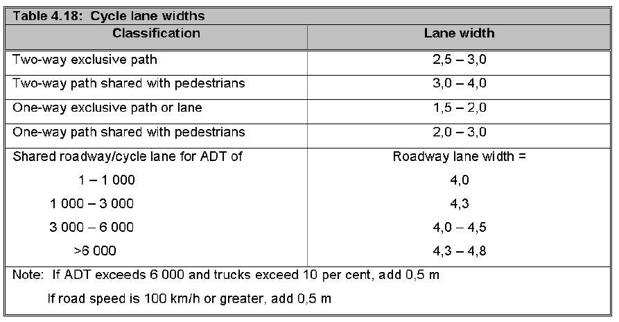
11 TRAVEL LANE For vehicle traffic lanes on roads within built-up areas, the width can be estimated as WVL d min = [design speed/80] +2 Furthermore, the width of a bicycle lane on any road can be determined as WBL d min = [2+3a]/4 where WBL d min = width of bicycle lane and a = design number of bicycles riding side by side [2 a 4] For other types of conveyors, the minimum desirable width can be estimated as: WCL d min = W cv +0.5 Where WCL d min = minimum desirable width of special conveyor lane W cv = width of special conveyor (m)
12 SHOULDERS Shoulders are the usable areas immediately adjacent to the travelled way and are a critical element of the roadway cross-section. They provide: A recovery area for errant vehicles; A refuge for emergency and maintenance vehicles as well as stopped or disabled vehicles; Lateral support of the roadway structure; and In addition, shoulders support use of the road by other modes of transport, for example cyclists and pedestrians. Where bicyclists and pedestrians are to be accommodated on shoulders, a minimum usable shoulder width of 1.2 m should be used.
13 SHOULDERS Minimum width of safety enhancement places [shoulders and parking lanes] The minimum desirable width of a safety enhancement place depends on whether the place is designated to be used as a shoulder or a parking lane. In the case of a shoulder the usable width is usually between 0.6m and 3.6m depending on the class of road and traffic volume. In general, the usable width of a shoulder can be determined as: min d WSL = W + C v Where: WSL min d = minimum desirable useable width of shoulder (m) W v = width of design vehicle (m) C w = clearance [usually between 0 and 1.5 meters] In the case of a parking lane, the width depends on the type of parking (parallel or angled) which will be allowed. In general, for parallel parking, the minimum and desirable widths are 3.0m and 3.6m respectively. w
14 SHOULDERS Where roadside barriers, walls or other vertical elements are present, it is desirable to provide a shoulder width enough that the vertical elements will be offset a minimum of 0.6 m from the outer edge of the usable shoulder. Shoulders widths as recommended by the ERA design Guide Design Standard Rural Terrain/Shoulder Width (m) Town Section Widths (m) Flat Rolling Mountainous Escarpment Shoulder Parking Foot Lane*** way Median! DS n/a (min) (min) DS n/a Barrier! DS n/a n/a DS n/a n/a DS5 * n/a n/a DS6** n/a n/a DS7 1.0 (earth) 1.0 (earth) 1.0 (earth) 1.0 (earth) n/a n/a + n/a + n/a DS8** n/a n/a + n/a + n/a DS9** n/a n/a + n/a + n/a DS10** n/a n/a + n/a + n/a

15 SHOULDERS Shoulders widths as recommended by the SA design Guide
16 SHOULDERS Shoulders should be: continuous and have the same width on structures as approach roadways. Flush with the roadway surface and abut the edge of the traveled way. Sloped to drain way from the traveled way Bituminous and concrete surfaced roads 2 to 4 % Gravel surfaced shoulders 4 to 6 % Turf shoulders 6 to 8 % Where curbed, appropriate slope should be used with the drainage system to prevent ponding on the traveled way. If shoulders are to function effectively, they should be sufficiently stable to support occasional vehicle loads in all kinds of weather without severe distress.
17 SHOULDERS Where the traffic situation demands a dual-carriageway crosssection, the greatest width of shoulder, i.e. three meters, is called for. This width would apply to the outer shoulder. The inner shoulder need only be one meter wide: to protect the integrity of the pavement layers; to avoid drop-offs at the lane edge; and provide space for road markings provided the median island is not curbed, thus allowing a disabled vehicle to be moved clear of the adjacent lane.
18 TRAFFIC LANE Minimum desirable Number of Traffic Lanes for each category of conveyors: The desirable number of traffic lanes for each designated category of conveyors is dependent on the design entry flow rate and design service flow rate and can be estimated as: min DDFR( m) N d ( m) = DSFR Where: N min d (m) = desirable minimum number of lanes for a category m DDFR(m) = design demand flow rate for m in pcph per direction of flow DSFR = design service flow rate (pcph per traffic lane)
19 TRAFFIC LANE Cross Slope or Camber of a Traffic Lane Undivided travelled ways on tangents or on flat curves, have a crown or high point at the middle and a cross slope downward both edges. The cross slope may be a plane or rounded section or a combination. Rounded cross sections are parabolic and advantageous because the slope steepness towards the edge, but more difficult to construct. On divided highways each one-way travelled way may be crowned as on two-lane highways or it may have a unidirectional across slope across the entire width of the travelled way. The cross slope is largely dependent on the type of surfacing: high type %; and low type surfacing 2-6%.
20 TRAFFIC LANE Cross Slope or Camber of a Traffic Lane The four main causes of poor skid resistance on wet pavements are Rutting accumulates water in the wheel paths Polishing reduces the pavements micro-texture Bleeding covers the micro-texture Dirty covers micro texture
21 TRAFFIC LANE AUXILIARY LANES Auxiliary lanes at intersection, interchanges and on networks often help to facilitate traffic movements and are located immediately adjacent to the basic lanes. Auxiliary lanes at intersections and interchanges are mainly used as turning lanes (either to the left or to the right; the turning lanes are principally intended to remove slower vehicles, or stopped vehicles waiting for a gap in opposing traffic, from the through traffic stream hence increases the capacity of the through lanes) On network links, auxiliary lanes are climbing and passing lanes. Climbing lanes are often referred to as truck lanes, crawler lanes, overtaking lanes or passing lanes. The function of climbing lanes is, however, very different from that of passing lanes. Such added lanes should be as wide as the through-traffic lanes but not less than 3 m.
22 TRAFFIC LANE MEDIANS Median is the portion of a highway separating opposing directions of the traveled way and the principal functions are to: Separate opposing traffic reduce the probability of head-on accidents (achieved through selection of a suitable width of median or the use of median barrier) Provide recovery area during emergency (research has found that the minimum median width required for recovery of out of control vehicles and most of head-on crashes is 9 m), Provide stopping area for left and U-turning vehicles (the width of median should be sufficient enough to accommodate left turning vehicles) Provide refuge for pedestrians (pedestrians do not feel safe on median islands narrower than about 2m, suggesting that the median should have a width of the order of 5.5 to 6.0 meters. Reduce headlight glare
23 TRAFFIC LANE MEDIANS Median can be either raised, flush or depressed. Depressed medians are normally used in rural areas and raised medians in urban areas. This differentiation between rural and urban areas arises for two reasons: drainage and safety. According to AASHTO, median width vary between 1.2 up to 24 m or more depending on the availability of right-of-way Medians with a width of 9m or more allow for individual grading of the two carriageways, but crashes at intersections increases with increasing width of median by virtue of the long travel distances that they impose on turning vehicles.
24 CURBS Curbs are raised or near-vertical elements that are located adjacent to the traveled way and are usually used: To control drainage Improve aesthetic by delineating the pavement edge Reduce right-of-way Delineation of pedestrian walkways Assistance in orderly roadside development Are classified as Barrier curbs vertical, designed for preventing vehicles from leaving the road, but should not be used along high speed roads as it is not forgiving. Mountable curbs are designed so that vehicles can cross them readily when the need arises.
25 TRAFFIC BARRIERS Traffic barriers are used to prevent vehicles that leave the traveled way from hitting and object that has greater crash severity potential than the barrier itself. Traffic barriers include Longitudinal barriers (along roadsides and in medians): primarily to redirect errant vehicles. They can be flexible, semi-rigid, or rigid depending on the amount of deflection that can be accommodated when the barrier is struck. Median barrier a longitudinal structure used to prevent an errant vehicle from crossing the portion of a divided highway separating the traveled way for traffic in the opposite directions Roadside barrier protect vehicles from causing hazards onto roadside and shield pedestrians Crash cushions: primarily to decelerate errant vehicles to a safe stop for shielding from hitting rigid objects along the roadsides such as piers, overhead sign supports, abutments, and retaining walls. Bridge railings prevent vehicles, pedestrians or cyclists from falling off the structure.
26 DRAINAGE CHANNELS AND SIDESLOPES Modern highway drainage design should incorporate safety, good appearance, control of pollution, and economical maintenance. The interrelationship b/n drainage channel and side slopes is important for safety (good roadside design reduces the potential severity of accidents). Drainage channels should have adequate capacity for the design runoff, provide for unusual storm drainage, and be located and shaped to provide a safe transition from the roadway to the back-slope. The depth of channel should be sufficient to remove surface water without saturation of the subgrade. Side slopes should be designed to ensure roadway stability and to provide a reasonable opportunity for recovery area for an errant vehicle.
27 SIDEWALKS Pedestrian traffic is not encouraged in the road reserves of freeways, expressways or other high-speed arterials and accommodation of pedestrian traffic is usually handled elsewhere. Side walks provided on urban or rural roads When pedestrian traffic is high along main or high speed roads When shoulders are not provided on arterials even when pedestrian traffic is low In urban areas, sidewalks are provided along both sides of streets to serve pedestrians access to schools, parks, shopping centers, and transit stops. The width of a sidewalk should not be less than 1.5m and a minimum width of 2m should be provided near hospitals and where wheelchair traffic could be expected. If the sidewalk is immediately adjacent to the curbing, the minimum width should be increased by about 0.6 to 1m to accommodate utilities. The normal cross-slope on a sidewalk is 2%. A grade separated pedestrian facility allows pedestrians and motor vehicles to cross at different levels, either over or under a roadway.
28 CYCLE PATHS If adequately planned, designed and maintained, cycle paths can play an important role in the transportation system. It is important to realize that cyclists need sufficient space to operate with safety and convenience rather than simply being assigned whatever space is left over after the needs of vehicular traffic has been accommodated. The basic requirements of cyclists are: Space to ride (1 m); A smooth surface; Speed maintenance, and Connectivity. Facilities for bicycles can take the form of a: Shared roadway/cycle lane where motor vehicles and bicycles travel in a common lane; Cycle lane, which is part of the travelled way but demarcated as a separate lane; Shoulder lane, which is a smooth, paved portion of the shoulder, properly demarcated by pavement markings or traffic signs. Cycle paths may be located within the road reserve or in an independent reserve.
29 CYCLE PATHS CYCLE PATHS
30 CYCLE PATHS CYCLE PATHS
31 SIDE AND BACK SLOPES Side slopes should be designed to insure the stability of the roadway and to provide a reasonable opportunity for recovery of an out-of-control vehicle. Three regions of the roadside are important when evaluating the safety aspects: the top of the slope (hinge point), the side slope, and the toe of the slope (intersection of the fore slope with level ground or with a back slope, forming a ditch).
32 SIDE AND BACK SLOPES When the safety aspect in relation to side slope is considered it will be important to see the three zones categorized in the new ERA Geometric Design Manual: Recoverable, Non-recoverable and Critical. According to ASSHTO Design Manual (Roadside Design Guide) the definition of the three zones are as follows: Recoverable slope: all embankment slopes 4:1 (H:V) or flatter. Motorists who encroach on recoverable slopes can generally stop their vehicles or slow them enough to return to the roadway safely. A non-recoverable slope is defined as one which is traversable, but from which most motorists will be unable to stop or return to the roadway easily. Vehicles on such slopes typically can be expected to reach the bottom. All slopes in the range of 3:1 to 4:1 (H:V) are categorized as a non-recoverable slope. A critical slope is one on which a vehicle is likely to overturn. Slopes steeper than 3:1 (H:V) generally fall into this category. For the critical slopes (steeper than 3:1(H:V)) it is recommended to put warning signs. This is the recommendation according to AASHTO Design Manual. The important aspect, which needs to analyze, is the standards sated by AASHTO is for roads having high level of serviceability (minimum design speed 65km/hr).
33 SIDE AND BACK SLOPES Table : Comparisons of different cut slopes and recommendation for low speed road <60kph Materia l type Earth or Soil Height of Slope (m) New ERA Design Manual Side Slope (V:H) Cut Fill Back Slope ERA/ TCDE Geometric Design Manual Side Slope (V:H) Cut Fill Back Slope f Kenyan Road Design Manual Side Slope (V:H) Cut Fill Back Slope Tanzanian Road Design Manual Side Slope (V:H) Cut Fill Back Slope Highway Design Reference Guide* Side Slope (V:H) Cut Fill B k Sl Recommendatio n Side Slope (V:H) 0.0m-1.0m 1:4 1:4 1:3 1:3 1:3 1:4 1:3-1:4 1:3 for poor clay 1:3 1:3 1.0m-2.0m 1 1:3 1:3 1:2 1:2 1:2 1:2 1:2-1:2 2:1 for good clay 1:2 1:2 Over 2.0 m 1 1:2 1:2 2:3 2:3 2:3 2:3 2:3-2:3 1:2 2:1 for granular 2:3 2:3 to martial 2:3 Cut Fill Back Slope for Cut (V:H) Rock 0.0m-2.0m 1 1:3 1:3 4:5 1: 4:5 2:1 1: ) 4:1 to 2:1 for 1: 4:5 2:1 Over 2.0m 1 1:2 1:2 1:1 2 1:1 4: Igneous rock 3:1 1:1 2 1:1 4:1 Weather 0.0m-2.0m ) 2:1 to 4:3 for 2:3 2:1 to to ed Rock Over 2.0m sedim. rock 1:1 3:1 10:1 4:1 3) 4:1 to 4:3 for Meta. rock Decom 0.0m-1.0m :3 1: :2 1:3 1:3 posed 1.0m-2.0m :2 1: to 1:2 1:2 Over 2.0 m :3 2: :1 2:3 1:1
34 ROAD SIDE DITCHES Are provided to remove the longitudinal and lateral incoming flood safely from the main road formation. Minimum depth of ditches should be 0.6m in mountainous and escarpment terrain, and 1.0m elsewhere, using a v-ditch configuration. Side drains should be avoided in areas with expansive clay soils such as black cotton soils. Where this is not possible, they shall be kept at a minimum distance of 4-6m from the toe of the embankment, dependent on functional classification (6m for trunk roads), as shown in Figure below. The ditch in this instance should have a trapezoidal, flat-bottom configuration.
35 Thank You!
Alberta Infrastructure HIGHWAY GEOMETRIC DESIGN GUIDE AUGUST 1999
 Alberta Infrastructure HIGHWAY GEOMETRIC DESIGN GUIDE AUGUST 1999,1'(; A ACCELERATION Data on acceleration from stop D-29 Effects of grade D-35 Intersections D-97, D-99 Lanes D-97, F-5, F-7, F-15, F-21,
INDEX. Geometric Design Guide for Canadian Roads INDEX
 Acceleration lane, see Lanes, Acceleration Access, 8.1 Access Management and Functional Classification 8.2 Access Management by Design Classification 8.3 Access Configuration 8.4 Building Set-Back Guidelines
Geometric designs for Safe Highways. Dr. Manoj M. Asst. Professor Department of Civil Engineering IIT Delhi
 Geometric designs for Safe Highways Dr. Manoj M. Asst. Professor Department of Civil Engineering IIT Delhi WORKSHOP-CUM-TRAINING PROGRAMME ON ROAD SAFETY 17th 21st September 2018 Outline Introduction Cross
(HIGHWAY GEOMETRIC DESIGN -1)
") LECTURE HOUR-19 TE-1(10CV56) UNIT-3 (HIGHWAY GEOMETRIC DESIGN -1) Width of carriage way: Width of the carriage way or the width of the pavement depends on the width of the traffic lane and number of lanes.
LECTURE HOUR-19 TE-1(10CV56) UNIT-3 (HIGHWAY GEOMETRIC DESIGN -1) Width of carriage way: Width of the carriage way or the width of the pavement depends on the width of the traffic lane and number of lanes.
ENGINEERING STANDARD FOR GEOMETRIC DESIGN OF ROADS AND STREETS ORIGINAL EDITION MAR. 1996
 ENGINEERING STANDARD FOR GEOMETRIC DESIGN OF ROADS AND STREETS ORIGINAL EDITION MAR. 1996 This standard specification is reviewed and updated by the relevant technical committee on Dec. 2000(1) and July.
Geometric Design Tables
 Design Manual Chapter 5 - Roadway Design 5C - Geometric Design Criteria 5C-1 Geometric Design Tables A. General The following sections present two sets of design criteria tables - Preferred Roadway Elements
Cross Section Elements
 Chapter Four Cross Section Elements Many of the basic geometric criteria for design of the various cross section elements were described as design standards in Chapter Three. This chapter provides more
WYDOT DESIGN GUIDES. Guide for. Non-NHS State Highways
 WYDOT DESIGN GUIDES Guide for Non-NHS State Highways 2014 GUIDE FOR Non-NATIONAL HIGHWAY SYSTEM (Non-NHS) STATE HIGHWAYS PRESERVATION REHABILITATION RECONSTRUCTION INTRODUCTION This Guide is directed to
WYDOT DESIGN GUIDES. Guide for. NHS Arterial (Non-Interstate)
") WYDOT DESIGN GUIDES Guide for NHS Arterial (Non-Interstate) 2014 GUIDE FOR NATIONAL HIGHWAY SYSTEM (NHS) HIGHWAYS (NHS ARTERIALS, Non-Interstate) PRESERVATION REHABILITATION RECONSTRUCTION INTRODUCTION
WYDOT DESIGN GUIDES Guide for NHS Arterial (Non-Interstate) 2014 GUIDE FOR NATIONAL HIGHWAY SYSTEM (NHS) HIGHWAYS (NHS ARTERIALS, Non-Interstate) PRESERVATION REHABILITATION RECONSTRUCTION INTRODUCTION
October 2004 REVISIONS (2) SUPERELEVATION DEVELOPMENT 11.3(2)
 SUPERELEVATION DEVELOPMENT 11.3(2)") October 2004 REVISIONS (2) Chapter 11 HORIZONTAL ALIGNMENT SUPERELEVATION DEVELOPMENT 11.3(2) Chapter 12 VERTICAL ALIGNMENT VERTICAL CURVES PASSING SIGHT DISTANCE 12.5(2) VERTICAL CURVES STOPPING SIGHT
October 2004 REVISIONS (2) Chapter 11 HORIZONTAL ALIGNMENT SUPERELEVATION DEVELOPMENT 11.3(2) Chapter 12 VERTICAL ALIGNMENT VERTICAL CURVES PASSING SIGHT DISTANCE 12.5(2) VERTICAL CURVES STOPPING SIGHT
PLACEMENT OF SIGNS RECOMMENDED PRACTICES SUB-SECTION
 Page 1 of 6 RECOMMENDED PRACTICES PART SECTION SUB-SECTION HIGHWAY SIGNS GENERAL General Proper positioning of signs is an important element in the overall control of traffic within a roadway network.
FOR HISTORICAL REFERENCE ONLY
 To: From: Subject: Electronic Distribution Recipients MINNESOTA DEPARTMENT OF TRANSPORTATION Engineering Services Division Technical Memorandum No. 12-14-B-03 December 18, 2012 Jon M. Chiglo, P.E. Division
Table of Contents. Introduction. Prompt List Arterials and Streets. Prompt List Interchange. Prompt List Intersections. Prompt List Limited Access
 Table of Contents Introduction Prompt List Arterials and Streets Prompt List Interchange Prompt List Intersections Prompt List Limited Access Prompt List MOT Prompt List Pedestrian Bicyclist Prompt List
Road Safety Audit training course. Motorways - safety issues of the motorway design
 Road Safety Audit training course Motorways - safety issues of the motorway design Jesper Mertner, Road safety auditor, COWI A/S 1 ROAD SAFETY AUDITING COURSE Content 1. Safety 2. Cross sections 3. Horizontal
Technical Memorandum. Shoulder Width Standards for State Highways. Expiration. Implementation. Introduction. Purpose
 Minnesota Department of Transportation Engineering Services Division Technical Memorandum No. 17-12-TS-05 Technical Memorandum To: Electronic Distribution Recipients From: Nancy T. Daubenberger, P.E. Divison
City of Roseville Section 13 Design Standards. _Bikeways January 2016 SECTION 13 BIKEWAYS
 SECTION 13 BIKEWAYS 13-1 GENERAL The City of Roseville bikeway standards are designed to insure that transportation and recreational bikeways are constructed in a manner that would provide a safe and comfortable
DISTRIBUTION: Electronic Recipients List TRANSMITTAL LETTER NO. (13-01) MINNESOTA DEPARTMENT OF TRANSPORTATION. MANUAL: Road Design English Manual
 MINNESOTA DEPARTMENT OF TRANSPORTATION. MANUAL: Road Design English Manual") DISTRIBUTION: Electronic Recipients List MINNESOTA DEPARTMENT OF TRANSPORTATION DEVELOPED BY: Design Standards Unit ISSUED BY: Office of Project Management and Technical Support TRANSMITTAL LETTER NO.
DISTRIBUTION: Electronic Recipients List MINNESOTA DEPARTMENT OF TRANSPORTATION DEVELOPED BY: Design Standards Unit ISSUED BY: Office of Project Management and Technical Support TRANSMITTAL LETTER NO.
GDOT Cross Section Elements. Course ID: GDOT PDH Credits
 GDOT Cross Section Elements Course ID: GDOT-01 2 PDH Credits Civil Engineer Educators LLC 1026 Timberwolf Lane Juneau, AK 99801 Email: support@civilpdh.com Chapter 6 Contents 6. CROSS SECTION ELEMENTS
Dr. Naveed Anwar Executive Director, AIT Consulting Affiliated Faculty, Structural Engineering Director, ACECOMS
 Dr. Naveed Anwar Executive Director, AIT Consulting Affiliated Faculty, Structural Engineering Director, ACECOMS Overview Highway Functions and Classifications Highway Design Components Design Control
Geometric design deals with the dimensioning of the elements of highways, such
 CHAPTER 15 Geometric Design of Highway Facilities Geometric design deals with the dimensioning of the elements of highways, such as vertical and horizontal curves, cross sections, truck climbing lanes,
Figure 1: Graphical definitions of superelevation in terms for a two lane roadway.
 Iowa Department of Transportation Office of Design Superelevation 2A-2 Design Manual Chapter 2 Alignments Originally Issued: 12-31-97 Revised: 12-10-10 Superelevation is the banking of the roadway along
MUTCD Part 6G: Type of Temporary Traffic Control Zone Activities
 MUTCD Part 6G: Type of Temporary Traffic Control Zone Activities 6G.01 Typical Applications Each temporary traffic control (TTC) zone is different. Many variables, such as location of work, highway type,
CHAPTER 16 PEDESTRIAN FACILITIES DESIGN AND TECHNICAL CRITERIA TABLE OF CONTENTS
 CHAPTER 16 PEDESTRIAN FACILITIES DESIGN AND TECHNICAL CRITERIA TABLE OF CONTENTS Section Title Page 16.1 General... 16-1 16.1.1 AASHTO Reference... 16-1 16.1.2 ADA Requirements... 16-1 16.2 Sidewalks...
To position power poles a safe distance from the road to minimise the likelihood of being accidentally hit by vehicles.
 Policy Statement Subject Placement of Rigid Distribution Poles Along Roads With Speed Limits Exceeding 70KM/H Approved by Robert Rogerson Signature & Date Distribution Standards and Policy Manager Authorised
General Design Factors
 Chapter 3: 3-1.0 Introduction General Design Factors Mn/DOT s goals include encouraging and accommodating safe bicycling. From a design perspective, these goals are achieved by first having an understanding
Chapter 4 On-Road Bikeways
 Chapter 4: 4-1.0 Introduction On-Road Bikeways This chapter provides guidelines to help select and design safe on-road bikeways. On-road bikeways include bicycle lanes, shared lanes, shoulders, and wide
Figure 3B-1. Examples of Two-Lane, Two-Way Marking Applications
 Figure 3B-1. Examples of Two-Lane, Two-Way Marking Applications A - Typical two-lane, two-way marking with passing permitted in both directions B - Typical two-lane, two-way marking with no-passing zones
Road Markings. Lecture Notes in Transportation Systems Engineering. Prof. Tom V. Mathew. 1 Overview 1. 2 Classification 2
 Road Markings Lecture Notes in Transportation Systems Engineering Prof. Tom V. Mathew Contents 1 Overview 1 2 Classification 2 3 Longitudinal markings 2 3.1 Center line.....................................
Policy Statement. Objective. Context. References and Supporting Documentation
 Policy Statement Subject Placement of Distribution Poles Along Roads With Speed Limits Not Exceeding 70km/h Approved by Robert Rogerson Signature & Date Distribution Standards and Policy Manager Authorised
3-13 UFC - GENERAL PROVISIONS AND GEOMETRIC DESIGN FOR ROADS, STREETS, WALKS, AND OPEN
 maintenance, and erosion. Stability is required to maintain the integrity of the pavement structure, and a slope stability analysis should be conducted for cuts and fills greater than 15 feet. For lower
Roadway Design Manual
 Roadway Design Manual Manual Notice Archive by Texas Department of Transportation (512) 302-2453 all rights reserved Manual Notice 2009-1 From: Manual: Mark A. Marek, P.E Roadway Design Manual Effective
References General Definitions
 Chapter 700 700.01 General 700.02 References 700.03 Definitions 700.04 Clear Zone 700.05 Hazards to Be Considered for Mitigation 700.06 Median Considerations 700.07 Other Features 700.08 Documentation
Shared Use Path Design
 12B-2 Design Manual Chapter 12 - Sidewalks and Bicycle Facilities 12B - Bicycle Facilities Shared Use Path Design A. Accessible Shared Use Path Design 1. General: Applicable portions from the following
Memorandum. Exhibit 60 SSDP To: Jenny Bailey, Senior Planner. From: Bill Schultheiss, P.E. (WA. P.E. #46108) Date: June 20, 2017
 Date: June 20, 2017") Memorandum To: Jenny Bailey, Senior Planner From: Bill Schultheiss, P.E. (WA. P.E. #46108) Date: June 20, 2017 Re: East Lake Sammamish Trail, Segment 2B Review King County has asked Toole Design Group
Memorandum To: Jenny Bailey, Senior Planner From: Bill Schultheiss, P.E. (WA. P.E. #46108) Date: June 20, 2017 Re: East Lake Sammamish Trail, Segment 2B Review King County has asked Toole Design Group
South Carolina Department of Transportation. Engineering Directive
 South Carolina Department of Transportation Engineering Directive Directive Number: ED-22 Effective: December 16, 2009 Subject: References: Purpose: This Directive Applies to: Considerations for Bicycle
This Chapter sets forth the minimum design, technical criteria and specifications to be used in the preparation of all roadway plans.
 4.1 GENERAL This Chapter sets forth the minimum design, technical criteria and specifications to be used in the preparation of all roadway plans. These Roadway Standards are for new construction and modification
Road Markings. Lecture Notes in Transportation Systems Engineering. Prof. Tom V. Mathew
 Road Markings Lecture Notes in Transportation Systems Engineering Prof. Tom V. Mathew 1 Overview The essential purpose of road markings is to guide and control traffic on a highway. They supplement the
Chapter 3 DESIGN SPECIFICATIONS
 Brampton PathWays Planning and Design Guidelines 27 Chapter 3 DESIGN SPECIFICATIONS 3.1 CLASS 1 MULTI-USE PATH Off-road multi-use trails are the backbone of the Brampton PathWays Network. They are typically
RURAL HIGHWAY SHOULDERS THAT ACCOMMODATE BICYCLE AND PEDESTRIAN USE (TxDOT Project ) June 7, Presented by: Karen Dixon, Ph.D., P.E.
 June 7, Presented by: Karen Dixon, Ph.D., P.E.") RURAL HIGHWAY SHOULDERS THAT ACCOMMODATE BICYCLE AND PEDESTRIAN USE (TxDOT Project 0-6840) June 7, 2016 Presented by: Karen Dixon, Ph.D., P.E., TTI Team: Kay Fitzpatrick, Raul Avelar, & Subasish Das Project
RURAL HIGHWAY SHOULDERS THAT ACCOMMODATE BICYCLE AND PEDESTRIAN USE (TxDOT Project 0-6840) June 7, 2016 Presented by: Karen Dixon, Ph.D., P.E., TTI Team: Kay Fitzpatrick, Raul Avelar, & Subasish Das Project
INTERSECTIONS AT GRADE INTERSECTIONS
 INTERSECTIONS 1 AT GRADE INTERSECTIONS INTERSECTIONS INTERSECTIONS = INTERRUPTED FACILITIES Definitions and key elements An intersection is defined as an area where two or more roadways join or cross.
Guide to Road Design Part 3: Geometric Design Session I 18 October 2016
 Guide to Road Design Part 3: Geometric Design Session I 18 October 2016 Today s moderator Angela Racz Online Training Coordinator Knowledge Transfer - ARRB Group P: +61 3 9881 1694 E: training@arrb.com.au
CHECKLIST 2: PRELIMINARY DESIGN STAGE AUDIT
 CHECKLIST 2: PRELIMINARY DESIGN STAGE AUDIT 2.1 General topics 2.1.1 Changes since previous audit Do the conditions for which the scheme was originally designed still apply? (for example, no changes to
CHAPTER 1 STANDARD PRACTICES
 CHAPTER 1 STANDARD PRACTICES OBJECTIVES 1) Functions and Limitations 2) Standardization of Application 3) Materials 4) Colors 5) Widths and Patterns of Longitudinal Pavement Marking Lines 6) General Principles
Off-Road Facilities Part 1: Shared Use Path Design
 Off-Road Facilities Part 1: Shared Use Path Design Presentation by: Eric Mongelli, P.E. Tom Huber October 9, 2012 FOLLOW THE CONVERSATION ON TWITTER Toole Design Group is live tweeting this webinar @tooledesign
ROUNDABOUTS/TRAFFIC CIRCLES
 GENERAL 1. Description This standard identifies minimum requirements that shall be met for Roundabouts and Neighborhood Traffic Circles in the design and construction of elements for Arlington County Horizontal
Design Criteria. Design Criteria
 F Design Criteria Design Criteria Ministry of Transportation Ministère des Transports DESIGN CRITERIA Page: 1 of 13 WORK PROJECT NO. N/A GO Bloomington Station TYPE OF PROJECT LOCATION Bloomington Road
H8 Signs, Supports and Poles
 Alberta Infrastructure and Transportation Roadside Design Guide November 2007 H8 Signs, Supports and Poles H8.1 Introduction This section identifies the appropriate roadside safety treatment for signs,
SECTION 1A NEW JERSEY TURNPIKE GEOMETRIC DESIGN
 SECTION 1A NEW JERSEY TURNPIKE GEOMETRIC DESIGN Table of Contents Page No 1A.1 GENERAL...1 1A.1.1 DESIGN CONTROLS...1 1A.2 MAINLINE ROADWAYS...4 1A.2.1 ROADWAY DESIGNATION...4 1A.2.2 DESIGN SPEED...4 1A.2.3
Driveway Design Criteria
 Design Manual Chapter 5 - Roadway Design 5L - Access Management 5L-4 Driveway Design Criteria A. General For efficient and safe operations, access drives and minor public street intersections can be improved
SECTION 12 ROAD MARKINGS AND DELINEATION
 SECTION 12 ROAD MARKINGS AND DELINEATION (Blank Page) MANUAL OF TRAFFIC SIGNS AND MARKINGS - Part III: Motorways and Expressways 12-1 12.1 GENERAL 12.1.1 INTRODUCTION The markings and delineation details
Section 4 Basic Geometric Design Elements
 4.1 General Section 4 Basic Geometric Design Elements BDC07MR-01 Geometric highway design pertains to the visible features of the highway. It may be considered as the tailoring of the highway to the terrain,
Recommended Roadway Plan Section 2 - Land Development and Roadway Access
 Recommended Roadway Plan Section 2 - Land Development and Roadway Access SECTION 2 Land Development and Roadway Access 2.1 Land Use and Access Management The Federal Highway Administration (FHWA) defines
On Road Bikeways Part 1: Bicycle Lane Design
 On Road Bikeways Part 1: Bicycle Lane Design Presentation by: Nick Jackson Bill Schultheiss, P.E. September 04, 2012 FOLLOW THE CONVERSATION ON TWITTER Toole Design Group is live tweeting this webinar
CHAPTER 3A. GENERAL PAGE CHAPTER 3B. PAVEMENT AND CURB MARKINGS PAGE
 Virginia Supplement to the 2009 MUTCD Revision 1 Page TC-3-1 PART 3. MARKINGS CHAPTER 3A. GENERAL PAGE Section 3A.01 Functions and Limitations Section 3A.02 Standardization of Application Section 3A.03
1.3.4 CHARACTERISTICS OF CLASSIFICATIONS
 Geometric Design Guide for Canadian Roads 1.3.4 CHARACTERISTICS OF CLASSIFICATIONS The principal characteristics of each of the six groups of road classifications are described by the following figure
NOT TO SCALE PUBLIC WORKS STANDARD DETAILS CURB DETAILS DATE: MARCH 2013 FILE NAME: CURB.DWG
 NOT TO SCALE PUBLIC WORKS STANDARD DETAILS CURB DETAILS DATE: MARCH 2013 FILE NAME: CURB.DWG NOT TO SCALE PUBLIC WORKS STANDARD DETAILS SIDEWALK RAMPS DATE: MARCH 2013 FILE NAME: SIDEWALK RAMPS.DWG NOT
Chapter 3 - Local Urban Road System CHAPTER 3 LOCAL URBAN ROAD SYSTEM
 CHAPTER 3 LOCAL URBAN ROAD SYSTEM 3.0 INTRODUCTION As in Chapter 2 for the local rural road system, the local urban road system also utilizes the concepts of land use context, functional classification
Appendix T CCMP TRAIL TRAFFIC & TRANSPORTATION DESIGN STANDARD
 Appendix T CCMP 3.3.4 TRAIL TRAFFIC & TRANSPORTATION DESIGN STANDARD 3.3.4 Trail Traffic and Transportation Design Multi-use trails have certain design standards, which vary depending on the agency that
Off-road Trails. Guidance
 Off-road Trails Off-road trails are shared use paths located on an independent alignment that provide two-way travel for people walking, bicycling, and other non-motorized users. Trails specifically along
GDOT Elements of Design. Course ID: GDOT PDH Credits
 GDOT Elements of Design Course ID: GDOT-06 3 PDH Credits Civil Engineer Educators LLC 1026 Timberwolf Lane Juneau, AK 99801 Email: support@civilpdh.com Chapter 4 Contents 4. ELEMENTS OF DESIGN 1 4.1. Sight
2.0 LANE WIDTHS GUIDELINE
 2.0 LANE WIDTHS GUIDELINE Road Engineering Design Guidelines Version 2.0.1 May 2018 City of Toronto, Transportation Services City of Toronto Page 0 Background In early 2014, Transportation Services initiated
11 CHECKLISTS Master Checklists All Stages CHECKLIST 1 FEASIBILITY STAGE AUDIT
 11 CHECKLISTS 11.1 Master Checklists All Stages CHECKLIST 1 FEASIBILITY STAGE AUDIT 1.1 General topics 1. Scope of project; function; traffic mix 2. Type and degree of access to property and developments
General References Definitions. (1) Design Guidance. (2) Supporting Information
 Design Guidance. (2) Supporting Information") Chapter 1240 Turning Roadways 1240.01 General 1240.02 References 1240.03 Definitions 1240.04 Turning Roadway Widths 1240.05 Documentation 1240.01 General The roadway on a curve may need to be widened to
Chapter 1240 Turning Roadways 1240.01 General 1240.02 References 1240.03 Definitions 1240.04 Turning Roadway Widths 1240.05 Documentation 1240.01 General The roadway on a curve may need to be widened to
Grade Separated Intersection
 Grade Separated Intersection Lecture Notes in Transportation Systems Engineering Prof. Tom V. Mathew Contents 1 Overview 1 2 Classification of Intersection 2 2.1 Grade Separated Intersection...........................
SECTION 12 ROAD MARKINGS AND DELINEATION
 SECTION 12 20 June 2009 Part 3: Motorways and Expressways CONTENTS Reference Page Page Number Date SECTION 12: MARKINGS AND DELINEATION 12.1 GENERAL... 12-1 June 2009 12.1.1 INTRODUCTION... 12-1 June 2009
Active Transportation Facility Glossary
 Active Transportation Facility Glossary This document defines different active transportation facilities and suggests appropriate corridor types. Click on a facility type to jump to its definition. Bike
Vertical Alignment. Concepts of design & guidelines Computing elevations along vertical curves Designing vertical curves
 Vertical Alignment Concepts of design & guidelines Computing elevations along vertical curves Designing vertical curves Flat terrain You can select smooth horizontal alignment and smooth vertical alignment
Design Overview. Section 4 Standard Plans for Design. Pedestrian Access Routes. Pedestrian Access Routes. Overview. Cross Slope
 Design Overview Section 4 Standard Plans for Design Fall, 2017 Ann Johnson, PE Services Brady Rutman, SRF Consulting Group Overview Design Basics Recommendations: The Zone System Driveway Crossings Pedestrian
CHECKLIST 6: EXISTING ROADS: ROAD SAFETY AUDIT
 CHECKLIST 6: EXISTING ROADS: ROAD SAFETY AUDIT 6.1 Road alignment and cross-section 6.1.1 Visibility; sight distance Is sight distance adequate for the speed of traffic using the route? Is adequate sight
BDC07MR-05. Section 6
 BDC07MR-05 Section 6 6.1 General Most highways intersect at grade. To minimize the resulting conflicts and to provide adequately for the anticipated crossings and turning movements, the geometric design
Appendix 3 Roadway and Bike/Ped Design Standards
 Appendix 3 Roadway and Bike/Ped Design Standards OTO Transportation Plan 2040 4/20/2017 Page A3-1 Adopted Standards The adopted OTO Design Standards and Major Thoroughfare Plan are contained herein.
Roadway Design Manual
 Roadway Design Manual Revised December 2013 2013 by Texas Department of Transportation (512) 302-2453 all rights reserved Manual Notice 2013-1 From: Manual: Mark A. Marek, P.E Roadway Design Manual Effective
Design of Suburban Highways
 Design of Suburban Highways by David L. Heavey, P.E. TABLE OF CONTENTS Introduction...3 Design Speed, Posted Speed and Operating Speed...4 Median Types...5 Raised Medians...9 Common Suburban Roadway Typical
American Railway Engineering and Maintenance of Way Association Letter Ballot. Draft
 American Railway Engineering and Maintenance of Way Association Letter Ballot 1. Committee and Subcommittee: Committee 5 Track Subcommittee 9 Road Crossings 2. Letter Ballot Number: 05-17-16 3. Assignment:
300 Cross Section Design
 300 Cross Section Design Table of Contents 301 Roadway Criteria... 3-1 301.1 Pavement... 3-1 301.1.1 General... 3-1 301.1.1.1 Disposition of Pavement Required Due to Maintenance of Traffic... 3-1 301.1.2
Geometric design is the process whereby the layout of the road in the terrain is designed to meet the needs of the road users.
 CHAPTER 3: GEOMETRIC DESIGN OF HIGHWAYS Geometric design is the process whereby the layout of the road in the terrain is designed to meet the needs of the road users. 3.1 Appropriate Geometric Standards
Chapter V TRAFFIC CONTROLS. Tewodros N.
 Chapter V TRAFFIC CONTROLS www.tnigatu.wordpress.com tedynihe@gmail.com Lecture Overview Traffic markings Longitudinal markings Transverse markings Object markers and delineator Traffic signs Regulatory
APPENDIX L. Design Criteria
 APPENDIX L Design Criteria DRAFT PRELIMINARY DESIGN CRITERIA Page 1 of 18 APPROVALS MANAGER, ENGINEERING CITY OF HAMILTON MANAGER, ENGINEERING REGION OF HALTON DATE This Design Criteria for the New East-West
APPENDIX D Draft Chapter 10 for AASHTO Roadside Design Guide
 APPENDIX D Draft Chapter 10 for AASHTO Roadside Design Guide Chapter 10 Draft Roadside Safety in Urban or Restricted Environments 10.0 OVERVIEW Generally, the principles and guidelines for roadside design
700 Multi-Modal Considerations
 700 Multi-Modal Considerations Table of Contents 701 Railroads... 7-1 701.1 Background... 7-1 701.2 Crossing At-Grade... 7-1 701.2.1 General... 7-1 701.2.2 Railroad Parallel to Highway... 7-1 701.3 Lateral
RAILWAY LEVEL CROSSING CHECKLIST Road Safety Review of Railway Crossings
 RAILWAY LEVEL CROSSING CHECKLIST Road Safety Review of Railway Crossings Location: Crossing No. Date of On-Site Inspection: (Day) / / (Night) / / Weather: CHECKLIST 5. - GENERAL TOPICS Level of control
Planning Guidance in the 2012 AASHTO Bike Guide
 Planning Guidance in the 2012 AASHTO Bike Guide Presentation by: RJ Eldridge Peter Lagerwey August 22, 2012 WEBINAR 2: PLANNING GUIDANCE IN THE 2012 AASHTO BIKE GUIDE Today s Webinar Significant Updates
Page 2D-10 Added the following language at the end of the paragraph under REFINING HORIZONTAL ALIGNMENT ; See Chapter 2A, Section 2A-6.
 ROAD DESIGN MANUAL REVISIONS January, 2017 CHAPTER 1B Page 1B-12 Added the following language (Definition); NORMAL CROWN - Undivided travel ways on tangents shall have a crown or high point in the middle
City of Vallejo Traffic Calming Toolbox
 City of Vallejo Traffic Calming Toolbox June 1, 2013 Final Table of Contents Introduction... 1 Non-Physical Devices... 3 High-Visibility Crosswalk... 3 In Pavement Lighted Crosswalk... 4 Rapid Flashing
Access Location, Spacing, Turn Lanes, and Medians
 Design Manual Chapter 5 - Roadway Design 5L - Access Management 5L-3 Access Location, Spacing, Turn Lanes, and Medians This section addresses access location, spacing, turn lane and median needs, including
THE FUTURE OF THE TxDOT ROADWAY DESIGN MANUAL
 THE FUTURE OF THE TXDOT ROADWAY DESIGN MANUAL Kenneth Mora, P.E. (Design Division) 10/10/2017 Table of contents 1 2 Reduction in FHWA design controlling criteria Innovative Intersection Guidance 3-7 8-42
PENNDOT HPMS DATA COLLECTION GUIDE. Bureau of Planning and Research Transportation Planning Division April 2016 (Updated March 2018)
") PENNDOT HPMS DATA COLLECTION GUIDE Bureau of Planning and Research April 2016 (Updated March 2018) State Street Dauphin County NOTES INTRODUCTION The purpose of this document is to provide you with some
PENNDOT HPMS DATA COLLECTION GUIDE Bureau of Planning and Research April 2016 (Updated March 2018) State Street Dauphin County NOTES INTRODUCTION The purpose of this document is to provide you with some
Section 3A.04 Colors. Section 3B.10 Approach Markings for Obstructions
 Section 3A.04 Colors Markings shall be yellow, white, red, or blue, or purple. The colors for markings shall conform to the standard highway colors. Black in conjunction with one of the above colors shall
Chapter 33. Grade Separated Intersection Overview Classification of Intersection Grade Separated Intersection
 Chapter 33 Grade Separated Intersection 33.1 Overview An intersection is the area shared by the joining or crossing of two or more roads. Since the main function of an intersection is to enable the road
Existing conditions of each bridge and repair plan are presented in Table
 2.2.2.5 Drainage Structure (1) Bridge Along the concerned section of this project road, there are 4 constructed bridges. The carriageway widths of existing bridges are designed to fit with existing road
10.0 CURB EXTENSIONS GUIDELINE
 10.0 CURB EXTENSIONS GUIDELINE Road Engineering Design Guidelines Version 1.0 March 2017 City of Toronto, Transportation Services City of Toronto Page 0 Background In early 2014, Transportation Services
Auckland Transport Code of Practice 2013
 P age 234 9 Roadside Restraint Devices 9.1 Scope This chapter includes the following: Road Safety Barrier Systems Fences Railings Bollards Sight Rails It excludes: Fences and restraints required within
DEFINITIONS Activity Area - Advance Warning Area Advance Warning Sign Spacing Advisory Speed Approach Sight Distance Attended Work Space
 DEFINITIONS Activity Area - that part of a TTC zone activity area where the work actually takes place. It consists of the work space, traffic space and one or more buffer spaces. Advance Warning Area -
What Is a Complete Street?
 Session 5 Charleen Zimmer, AICP, Zan Associates May 5-7, 2010 What Is a Complete Street? May 2010 5-1 Not a Complete Street More of a Complete Street May 2010 5-2 Benefits of Complete Streets Safety for
DRAFT. Scholls Ferry Road Conceptual Design Plan Technical Memorandum Multi-Modal Examples. Multnomah County 1600 SE 190th Avenue Portland, OR 97233
 Technical Memorandum Multi-Modal Examples Prepared for 1600 SE 190th Avenue Portland, OR 97233 December 2008 CITATION This project is partially funded by a grant from the Transportation and Growth Management
301 Roadway Criteria... 1
 300 Cross Section Design TABLE OF CONTENTS 301 Roadway Criteria... 1 301.1 Pavement... 1 301.1.1 General... 1 301.1.1.1 Disposition of Pavement Required Due to Maintenance of Traffic... 1 301.1.2 Lane
DISTRIBUTION: Electronic Recipients List TRANSMITTAL LETTER NO. (17-01) MINNESOTA DEPARTMENT OF TRANSPORTATION. MANUAL: Road Design English Manual
 MINNESOTA DEPARTMENT OF TRANSPORTATION. MANUAL: Road Design English Manual") DISTRIBUTION: Electronic Recipients List MINNESOTA DEPARTMENT OF TRANSPORTATION DEVELOPED BY: Design Standards Unit ISSUED BY: Office of Project Management and Technical Support TRANSMITTAL LETTER NO.
DISTRIBUTION: Electronic Recipients List MINNESOTA DEPARTMENT OF TRANSPORTATION DEVELOPED BY: Design Standards Unit ISSUED BY: Office of Project Management and Technical Support TRANSMITTAL LETTER NO.
Chapter Twenty-eight SIGHT DISTANCE BUREAU OF LOCAL ROADS AND STREETS MANUAL
 Chapter Twenty-eight SIGHT DISTANCE BUREAU OF LOCAL ROADS AND STREETS MANUAL Jan 2006 SIGHT DISTANCE 28(i) Chapter Twenty-eight SIGHT DISTANCE Table of Contents Section Page 28-1 STOPPING SIGHT DISTANCE
Road Safety Facilities Implemented in Japan
 Road Safety Facilities Implemented in Japan 1 Road Safety Facilities 1.Guard Fence 2.Road Lighting 3.Other Road Safety Facilities 2 Road Safety Facilities 1.Guard Fence 2.Road Lighting 3.Other Road Safety
PENNDOT HPMS DATA COLLECTION GUIDE
 PENNDOT HPMS DATA COLLECTION GUIDE Bureau of Planning and Research April 2016 (Updated September 2017) State Street Dauphin County INTRODUCTION The purpose of this document is to provide you with some